Embed Size (px)
Citation preview

Arc Flash
Mitigation with Fuses
Mersen
Ferraz Shawmut is now Mersen

2
Peter Walsh, PE Industrial Solutions Engineer
•Member of IEEE 1584 Technical Committee
•Participant in NFPA 70E Technical Committee Meetings
•Technical Committee Member of NFPA 110
•Technical Committee Member of NFPA 111
•Member – National Electrical Code Making Panel 4 for 2008 cycle
•Representative to NEMA 8SG (Higher Voltage Fuses and Switchgear)
•OSHA Authorized Outreach Trainer for 10 and 30 Hour OSHA Courses
•Member of International Association of Electrical Inspectors
•Disclaimer- Speaking as individual and not giving an official position or interpretation from any Committee

3
Overview
Arc Flash Mitigation is easier with tools for various situations. Fuses can uniquely solve some challenges through current limitation. This webinar will review the concepts of using current limitation to reduce incident energy through low voltage UL and medium voltage E-Rated fuses. UL classifications will be correlated to their current limitation and arc flash reduction.
– UL LV Fuse Standards
– Current Limitation
– Regions of TC Curve: Time Delay, No Time Delay, and
Current Limitation – Medium Voltage –Transformer Primary Fusing to Reduce Arc Flash

4
Part 1. Common UL Fuse Types
■ UL Fuse Types
■ Comparisons

5
Class H250 Volt600 Volt
Class K250 Volt600 Volt
Non -Current Limiting 0 - 600 Amp
Class RK250 Volt600 Volt
Class J600 Volt
Current limiting0 - 600 Amp
Class T300 Volt600 Volt
Class L600 Volt
Class CC600 Volt
Class G480 Volt
Current LimitingOther Amp ranges
Low Voltage Fuses0 - 600 Volt
Branch Circuit
601-6000A 1/10-30A
1/2-60A

6
Fuse Characteristics
Amp Rating Voltage Rating Interrupting Rating AIC Time Delay or Not Degree of Current Limitation Mechanical Dimensions Manufacturer

7
Condensed UL Fuse Class Comparison
U/L Class H K-5 RK-5 RK-1 J LAmpere Rating 0-600 0-600 0-600 0-600 0-600 601-6,000Amps IR 10kA 50kA 200kA 200kA 200kA 200kACurrent Limitation None Some Some Best Best VariesOverload Region 0-10x 0-10x 0-10x 0-10x 0-10x 0-10x Non-Time Delay Region Over 10x Over 10x Over 10x Over 10x Over 10x Over 10x Current Limiting Region None Over 65x Over 65x Over 30x Over 30x 30-40+x
Typical Fuse RFS OTS TRS-R A6D-R AJT A4BQA4BYA4BT

8
RK5 Time Delay Fuse

9
RK1 Dual Element Fuse

10
Part 2. Current Limitation
■ Concept of Current Limitation ■ Affect on Incident Energy
11
NEC 240.2 Definitions.
Current-Limiting Overcurrent Protective Device. A device that, when interrupting currents in its current-limiting range, reduces the current flowing in the faulted circuit to a magnitude substantially less than that obtainable in the same circuit if the device were replaced with a solid conductor having comparable impedance.

12
Incident Energy
IE is proportional to I2 x t IE can increase with lower currents if the duration is extended

13
Fuse Mitigation Strategy
■ Reduce incident energy by properly applied
current limiting fuses
■ Effective solution when fault levels are high

14
Current Limitation

15
RK5
RK1 J
Current Limitation Comparison

16
Fuse Energy Clearing I2t Comparison
100A UL Class RK5 = 50,000 I2t maximum rating 100A UL Class RK1 = 10,000 I2t maximum rating 80% Reduction by Replacing RK5 with RK1 for high fault conditions
17
Part 3. Regions of the Fuse Time-Current Curve
■ Time Delay Region
■ No Intentional Time Delay Region ■ Current Limitation Region

18
Transition Between TD and Non-TD
10X = 1,000 A
100A RK1 100A RK5

19
30X 65X
30X200 = 6,000 65X200 = 13,000
Transition to CL
200A RK1 200A RK5

20
Incident Energy
0
1
2
3
4
5
0 5 10 15 20 25 30
Bolted Fault In kA
Inci
den
t E
ner
gy
in c
al/c
m
Class RK1 200A
Fuse Curve from IEEE-1584

21
Circuit Breaker Equation from IEEE-1584

22
0
10
20
30
40
6 Cycle AJT200
6 Cycle 7.8 9.6 11.4 13.1 14.8 16.5 18.2 19.9 21.6 23.2AJT200 0.3 0.3 0.3 0.3 0.3 0.3 0.3 0.3 0.3 0.3
20 25 30 35 40 45 50 55 60 65
Cal/cm2
Available Fault Current kA
Using IEEE 1584 (2002) equations
Current Limitation Can Reduce Arc Energy

23
Arc Flash Design Example
600 V Motor Control Centers- If they are supplied by a maximum of a A4BQ800 fuse, many times the MCC is the safest category for Arc Flash (Incident Energy below 1.2 Cal/cm3) because the minimum available fault current will operate the fuse quickly at low currents and current limitation will activate at high faults.

24
Incident Energy vs. Minimum Bolted Fault Current at 600V

25
30x = 24Ka
Transition to CL
800A A4BQ 800A A4BT

26
Improved Energy Let Through Performance
Easily input exact fuse characteristic without maintenance people
substituting later
Improved interrupting ratings
Suggestion-Standardize on UL Class RK1 Fuses before Data Gathering for AF Study

27
Part 4. Primary Fuse Selection to Mitigate Secondary Incident Energy
■ Example Application ■ Considerations ■ Results

28
Figure 1
Switchgear with no main switch fed by 1,000kVA Transformer. Short circuit protection for switchgear bus is provided by primary fuse.

29
Incident Calculation Results
9F62DDD080
Percent of Iarc Iarc Secondary Iarc Primary
Total Clearing
Time Incident*
Energy
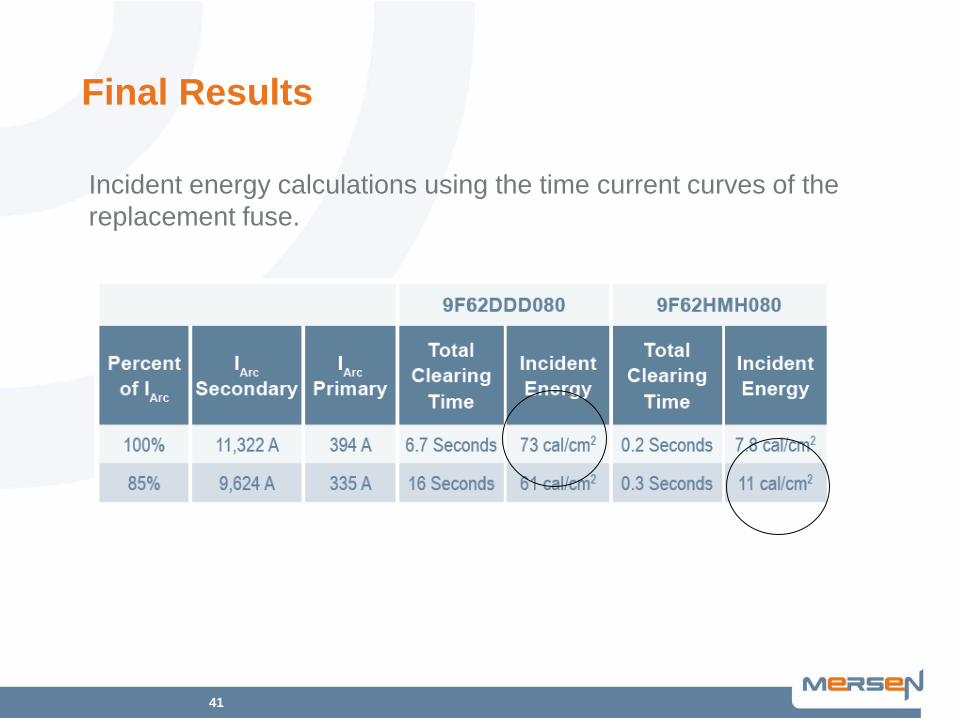
100% 11,322 A 394 A 6.7 Seconds 73 cal/cm2
85% 9,624 A 335 A 16 Seconds 61 cal/cm2

30
Figure 2 Time current curve for original primary fuse.

31
If It Were a Relay, You Would Adjust the Curve
Some fuses can have different curves but still meet the other application requirements Selecting different fuse curves can reduce the Arc Flash Incident Energy

32
Factors and Considerations for the Selection of a Transformer Primary Fuses
To reduce arc flash hazards and maintain reliable operation of the primary fuse, an arc flash energy objective must be added to the protection objectives of the primary fuse. Before changing the fuse to get a faster clearing time for the Iarc values, it is essential to review the other factors that affect selection of a transformer primary fuse. These factors include:
• System considerations • Transformer characteristics • NEC requirements • Fuse characteristics

33
System Considerations
Source Impedance-Fault current System Voltage Cable type and Length Coordination

34
Transformer Characteristics
Inrush at 25X at 0.01 seconds (½ cycle) Inrush at 8X or 10X at 0.1 second Damage Curve by ANSI C57.109 Transformer Ratings for full load Percent Impedance Z% Turns ratio Connection, i.e. Delta-Wye

35
NEC Requirements
Article 450.3 controls the maximum fuse size Articles 110.9 and 490.21(B) require adequate interrupting rating Article 490.21(B)3 require adequate voltage rating Article 240.100(C) requires adequate short circuit protection of cables feeding the transformer primary
36
Fuse Characteristics
ANSI/IEEE C37-40 Covers service conditions ANSI/IEEE C37.41 Specifies tests that prove the compliance to the standard
ANSI/IEEE C37.46 Specifies fuse characteristic and ratings

37
Figure 5
38
Other Considerations
Even if the new fuse is great electrically, it still has to fit physically In addition to having enough space, mounting can be an issue

39
Figure 6- Common Fuse Mounting Types

40
Time Curves A. Magnetizing Inrush Current at 0.1
sec (8 x Transformer primary FLA)
B. Magnetizing Inrush Current at 0.01 sec (25 x Transformer primary FLA) C. ANSI C57 Transformer Damage Curve shifted for phase to ground through faults D. Cable Damage Curve E. Largest feeder breaker time current curve F. Original fuse curve G. 9F60HMH080 (80E) time current curve. T1. Clearing time for 100% Iarc (11,322A;0.2 seconds) T2. Clearing time for 85% Iarc (9,624A;0.3 seconds)
41
Final Results
Incident energy calculations using the time current curves of the replacement fuse.

42
Summary - Questions?
Arc Flash Mitigation is easier with tools for various situations. Fuses can uniquely solve some challenges through current limitation. This webinar reviewed the concepts of using current limitation to reduce incident energy through low voltage UL and medium voltage E-Rated fuses. UL classifications were correlated to their current limitation and arc flash reduction.
– UL LV Fuse Standards
– Current Limitation
– Regions of TC Curve: Time Delay, No Time Delay, and
Current Limitation – Medium Voltage –Transformer Primary Fusing to Reduce Arc Flash

43
Cable Limiter Impact
Question: I would like to find out if cable protectors can be used on the secondary side of transformers such to lower the incident energy available on the line side of the secondary main disconnecting device?

44
EP.Mersen.com

45
Peter Walsh, PE