Embed Size (px)
Citation preview

SALT WATER CHLORINE GENERATOR
AQUAPURE®

2
Zodiac Academy [email protected]
www.zodiacacademy.com
Zodiac® Pool Systems, Inc. 1-800-822-7933 Regional Extension_________________ www.ZodiacPoolSystems.com
Instructor: _____________________________________Email:___________________________
Sales person: ___________________________________Phone:__________________________
Sales person: ___________________________________Phone:__________________________
Sales person: ___________________________________Phone:__________________________
Sales person: ___________________________________Phone:__________________________
Service Manager: ________________________________Phone:__________________________
Service Manager: ________________________________Phone:__________________________
IMPORTANT SAFETY INSTRUCTIONSThe information contained in this technical guide is intended for Zodiac trained service personnel only. Electrical installation and repairs should only be performed by a certified electrician or Zodiac trained professional. and must comply with all national electric codes (NEC®, Canadian, etc.). state and local law, ordinances, codes and regulations.
If you have not received training, do not attempt any of the electrical repairs presented in this document. Contact Zodiac Pool Systems, Inc. at 1-800-822-7933 for assistance.
Read and follow all instructions carefully.When servicing equipment, basic safety precautions should always be followed including those listed below.
TO REDUCE THE RISK OF ELECTRICAL SHOCK:• Disconnect main power to pool equipment area prior to any service or repairs.
• Keep all electrical equipment at least 10 feet (3m) from inside wall of pool or spa.
• Connect equipment only to a receptacle (cord models) or circuit (hardwired) protected by a ground fault circuit interrupter (GFCI).
• Use only copper conductors and supply wires suitable for the specific device.
• Replace damaged power cord(s) immediately and use only identical replacement parts.
• Do not bury power cord(s). Position cord(s) to minimize abuse from lawn mowers, hedge trimmers and other equipment.
• Do not install or service equipment if precipitation is present or imminent.
TO REDUCE EQUIPMENT WATER PRESSURE HAZARD:• Always turn pump off to release pressure prior to removing or installing in-line equipment.
• To avoid equipment damage, do not exceed water pressure (psi) specifications for the device.
To reduce the risk of injury, do not permit children to operate, handle or play on equipment.

1.9 lbs. 1.38 lbs 1.25 gallons 1.25 lbs
0.95 lbs. .69 lbs. .625 gallons .625 lbs.
Calcium Hypochlorite
90% Tri-Chlor Tabs
Liquid Chlorine (12.5%)
Gas Chlorine
700 1400
Sizing and Chlorine Production
700 Cell for up to = 12,000 Gallons* 1400 Cell for up to = 40,000 Gallons*
* Use common sense when sizing!
6613AP
PLC1400
Finished Goods Part Numbers “Chlorine Generators”
Cell Model: PLC = Cell Kit FSOFT = Cell Kit with Nature2® Vessel
Size: 1400 = 14 Plate Cell 700 = 7 Plate Cell
Power Pack Model: 6613AP = PureLink™ - Standard Power Center 6614AP = PureLink - Sub Panel Power Center APUREM = Stand alone AquaPure®/Fusion Soft

Water
HH
Making Chlorine (from salt water)
Electrolysis
HH
HH
H
H
H
H
H2 Hydrogen Gas
O2 Oxygen Gas
H2O Water
+

Electrolysis (Breaks apart molecules)
H H
O
O
H H
H2 Hydrogen Gas
O2 Oxygen Gas
&
Alternatives That Aren’t
Na Cl Salt
H2 0 Water
+ =
NaClO HClO & OCL-
Electrolysis (Breaks apart molecules)
12% 6% &
concentration
Liquid chlorine ratio of Hypochlorous Acid to Hypochlorite ion is nearly 100:0 due to its very high pH
H
H
H
Chlorine 101
Hypochlorous acid Sodium Hypochlorite
3 Primary Compounds in ‘Chlorine’ (aka Bleach)
Water
Strong Disinfectant (Unstable in pH neutral water)
Mild Disinfectant & Bleaching Agent
Packaging & Dilution
N
H
H H
Ammonia
Anything Organic bodily fluids, Fertilizer, Algae,
H
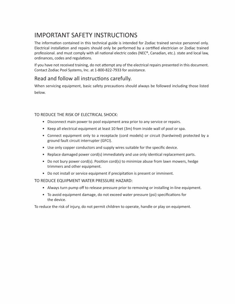
Pool Biology .
Hypochlorous acid (unstable)
Chlorine Attacks Ammonia
Ammonia Sources Bodily fluids & organic waste (ie. Sweat, Urine, Saliva, etc)
Lawn Fertilizers, Rain, & almost any organic material
NH H
Ammonia
Chloramine aka: “combined chlorine”
H
Hydroxide ion
Water
Bad Stuff • People say: “smells like chlorine” • Respiratory, Skin, & Eye Irritant
Sodium Hypochlorite
H
Pool Biology . Elimination of Chloramine
NH
Pungent “chlorine” Odor Stable… difficult to remove
Sodium Hypochlorite Chloramine
aka: “combined chlorine”
Salt “Super Chlorination”
Oxidized / Reduced to Filterable Ash
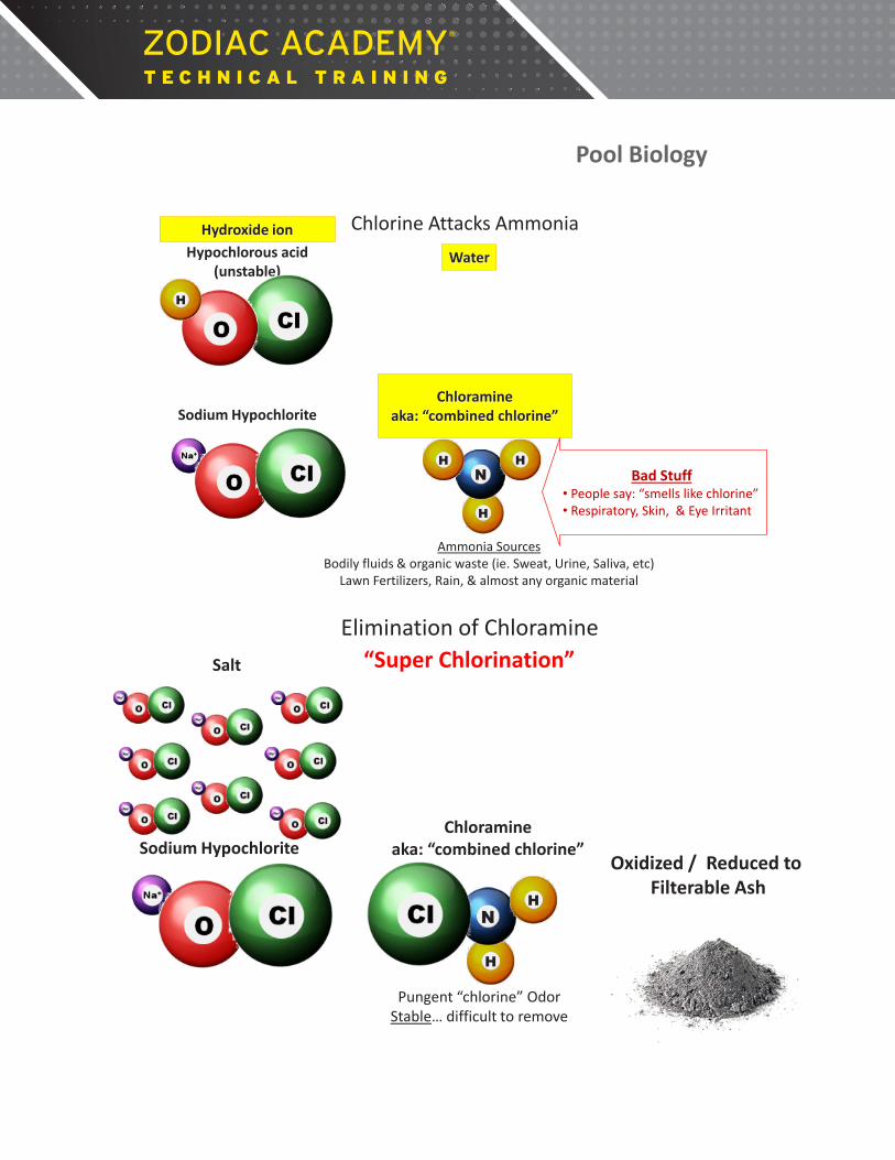
Summary
salt water
chlorine
Chloramines + Water Aka: “combined chlorine”
By-product: Chloramines & Water
Sanitize (Kill)
H
NH
Oxidize (Burn) Chloramines By-product: Ash & Salt
Ash Filtration
8
Notes:

Sub Panel PureLink™ Power Center Components
9
Notes:
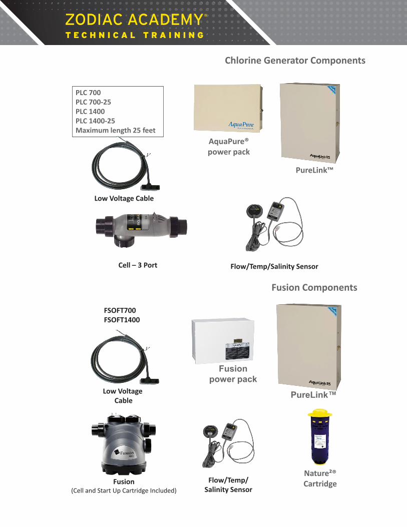
PureLink™
PLC 700 PLC 700-25 PLC 1400 PLC 1400-25 Maximum length 25 feet
Low Voltage Cable
Flow/Temp/Salinity Sensor Cell – 3 Port
AquaPure® power pack
Chlorine Generator Components
PureLink™
Fusion power pack
FSOFT700 FSOFT1400
Low Voltage Cable
Flow/Temp/ Salinity Sensor
Fusion (Cell and Start Up Cartridge Included)
Nature²® Cartridge
Fusion Components

New “Pig Snout” Design
In-line interface module
Release Fall 2014
• PGM “A” Firmware 02110A10 and later • PGM “B” ALL firmware prior to 02110A10 • Hold “Sel” for 5 sec’s to select PGM • Wait 5 minutes to allow for calibration
Simple Installation & Service
Tri-Sensor Improvements
Changed from three to two studs. The heated and reference temp sensors are now utilizing the salinity studs to transfer heat to the water
Attention Letter (in box)

Nature2® Benefit
• The bactericidal qualities of silver reduce the amount of chlorine required to maintain the pool. The copper inhibits algae growth.
• By lowering the output of the Fusion Soft, the pool water quality dramatically improves and the life of the electrolytic cell is extended
Nature2® Minerals
• Copper – inhibits algae growth – regularly sold as algaecides.
• Silver – known bactericide – used for thousands of years to control bacteria in water, milk and on skin.
• Porous Alumina – releases silver & copper – assists in trapping nuisance metals, algae & bacteria.
Nature2® Facts
• Copper is released into the pool at low levels – .02 ppm - .06 ppm.
• Silver is maintained throughout the cartridge life (6 months) at .01 ppm - .05 ppm.
• Minimum pump run time – 6 hours – can be run 24
hours if needed.
Wrong
Installation Plumbing

Installation Plumbing Remember in the process of making chlorine, hydrogen gas is also produced, therefore follow plumbing recommendations to prevent damage.
13 7/8” Cut Out
Installation Plumbing
13 7/8” Cut Out
Installation Plumbing Installation
Plumbing
OK but not recommended
Installation Plumbing
Not recommended
Installation Plumbing
Wrong
Installation Plumbing
13 7/8” Cut Out
11 1/8” Center of Pipe
Installation Plumbing

Installation Electrical Control Center must be grounded, bonded and wired to the load side of the circulation pump.
Installation Electrical 230 VAC Wiring
Ground Wire
Bond Wire
FIL- PMP
AUX 1
AUX 2
AUX 3
AUX 4
AUX 5
AUX 6
AUX 7
Transformer Primary: BLK/YEL BLK BLK/WHT & BLK/RED shorted
} 230 VAC
Installation Electrical 115 VAC Wiring
Ground Wire
FIL- PMP
AUX 1
AUX 2
AUX 3
AUX 4
AUX 5
AUX 6
AUX 7
Bond Wire
Transformer Primary: BLK/YEL & BLK/WHT = Neutral BLK & BLK/RED = 115 VAC
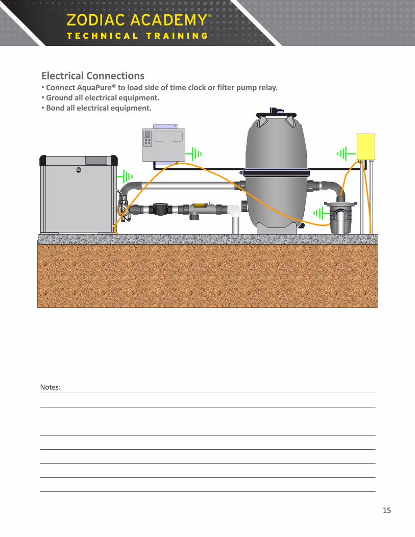
Electrical Connections Installation Electrical Connections • Connect AquaPure® to load side of time clock or filter pump relay. • Ground all electrical equipment. • Bond all electrical equipment.
15
Notes:

ORP
OPEN - AP700 SHORTED - AP1400 M-S
15
Green Black & White (+) (-)
ORP
POS – 2
POS - 1
BUZZER
OFF ---- ON -----
ADDRESS A B Device 0 0 # 1 1 0 # 2 0 1 # 3 1 1 # 4
A
B
DBI INTERFACE
Mechanical Sensor
ENB DIS
FLOW SENSOR
H - Temp
R - Temp Salinity
1 Amp FUSE
Salinity = 2.8 R Temp = 75 H Temp = 91
TEST POINTS
19 VAC VAC 1
VAC 2
120 mVDC
65 VAC 75 VAC
15 A
mp
FUS
E
+24 VDC
+5 VDC
COMMON
GROUND HEATER RESTING
CELL ON
FLOW
SERVICE
ORP
LOW SALT
+12 VDC
Installation Power Interface Identification
To covert a Power Interface Board (PIB) so it will function correctly with a 700 cell, cut the jumper.
Setup for 1400 Cell ORP
OPEN - AP700 SHORTED - AP1400 M-S
15
Green Black & White (+) (-)
ORP
POS – 2
POS - 1
BUZZER
OFF ---- ON -----
ADDRESS A B Device 0 0 # 1 1 0 # 2 0 1 # 3 1 1 # 4
A
B
DBI INTERFACE
Mechanical Sensor
ENB DIS
FLOW SENSOR
H - Temp
R - Temp Salinity
1 Amp FUSE
Salinity = 2.8 R Temp = 75 H Temp = 91
TEST POINTS
19 VAC VAC 1
VAC 2
120 mVDC
65 VAC 75 VAC
15 A
mp
FUS
E
+24 VDC
+5 VDC
COMMON
GROUND HEATER RESTING
CELL ON
FLOW
SERVICE
ORP
LOW SALT
+12 VDC
To covert a Power Interface Board (PIB) so it will function correctly with a 700 cell, cut the jumper.
Setup for 700 Cell
Installation Power Interface Identification
ORP
OPEN - AP700 SHORTED - AP1400 M-S
15
Green Black & White (+) (-)
ORP
POS – 2
POS - 1
BUZZER
OFF ---- ON -----
ADDRESS A B Device 0 0 # 1 1 0 # 2 0 1 # 3 1 1 # 4
A
B
DBI INTERFACE
Mechanical Sensor
ENB DIS
FLOW SENSOR
H - Temp
R - Temp Salinity
1 Amp FUSE
Salinity = 2.8 R Temp = 75 H Temp = 91
TEST POINTS
19 VAC VAC 1
VAC 2
120 mVDC
65 VAC 75 VAC
15 A
mp
FUS
E
+24 VDC
+5 VDC
COMMON
GROUND HEATER RESTING
CELL ON
FLOW
SERVICE
ORP
LOW SALT
+12 VDC
Installation Power Interface Identification
To covert a Power Interface Board (PIB) so it will function correctly with a 700 cell, cut the jumper.
Setup for 1400 Cell
16
Notes:

Water Chemistry
• Balance the pool water • Super chlorinate if needed
– Do not use a metal base algaecide – Metals in the water increases the conductivity
of the water. – Increased conductivity can damage the cell
Water Chemistry
• Balance the pool water • Super chlorinate if needed
– Do not use a metal base algaecide – Metals in the water increases the conductivity
of the water. – Increased conductivity can damage the cell
Water Chemistry
• Free chlorine - 1.0 to 3.0 ppm (.5 possible with Nature²) • pH - 7.4 to 7.6 • Total Alkalinity 80 to 120 ppm • Cyanuric Acid (Stabilizer) - 10 to 50 ppm • Total Dissolved Solids (TDS) – Less than 2000 ppm
(Subtract salinity level to arrive at corrected level)
Affect of pH on Chlorine
At a pH of 6.0, 96%* of the chlorine is in the active killing form, but too corrosive for pools and humans. At a pH of 7.0, 73%* of the chlorine is in the active killing form.
At a pH of 7.5, 50%* of the chlorine is in the active killing form. Ideal for pools.
At a pH of 8.0, only 21%* of the chlorine is in the active killing form.
*Chlorine in the molecular structure of hypochlorous acid. (the active killing form) The remaining percentage is in the form of a hypochlorite ion, which is also an active form of chlorine, but very weak and slow to kill.

14 13 12 11 10 9 8 7 6 5 4 3 2 1
Neutral
Acidic
Alkaline Liquid Chlorine
3” Chlorine Tablets
Chlorine from Generator (7.8)
Water Chemistry pH Scale
14 13 12 11 10 9 8 7 6 5 4 3 2 1
Neutral
Acidic
Alkaline Liquid Chlorine
3” Chlorine Tablets
Water Chemistry pH Scale
10 x 10 x 10 = 100 x 10 x 10 x 10 = 1,000 x 10 x 10 x 10 x 10 = 10,000 x
Salt (NaCl)
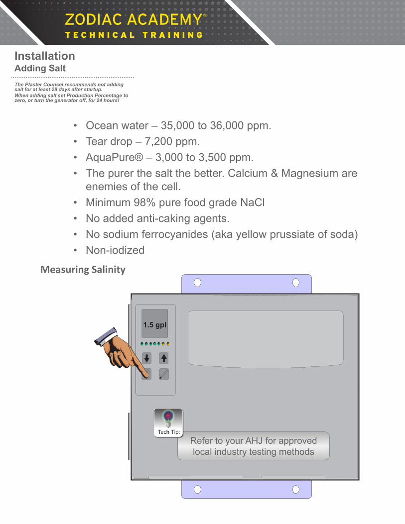
• Ocean water – 35,000 to 36,000 ppm. • Tear drop – 7,200 ppm. • AquaPure® – 3,000 to 3,500 ppm. • The purer the salt the better. Calcium & Magnesium are
enemies of the cell. • Minimum 98% pure food grade NaCl • No added anti-caking agents. • No sodium ferrocyanides (aka yellow prussiate of soda) • Non-iodized
Installation Adding Salt The Plaster Counsel recommends not adding salt for at least 28 days after startup. When adding salt set Production Percentage to zero, or turn the generator off, for 24 hours!
Measuring Salinity
1.5 gpl
Refer to your AHJ for approved local industry testing methods

CALIBRATED
NaCl Testing Salt Level Myron L Meter
X
Measuring Salinity
20
Notes:

POOL SIZE Current Salinity 10,000 14,000 18,000 20,000 24,000 28,000 30,000
0.0 gpl 250 lbs 350 lbs 450 lbs 500 lbs 600 lbs 700 lbs 750 lbs
1.0 gpl 165 lbs 230 lbs 300 lbs 330 lbs 400 lbs 460 lbs 495 lbs
1.5 gpl 125 lbs 175 lbs 225 lbs 250 lbs 300 lbs 350 lbs 375 lbs
2.0 gpl 85 lbs 120 lbs 150 lbs 170 lbs 205 lbs 240 lbs 255 lbs
2.5 gpl 40 lbs 60 lbs 70 lbs 80 lbs 100 lbs 110 lbs 120 lbs
3.0 gpl 0 lbs 0 lbs 0 lbs 0 lbs 0 lbs 0 lbs 0 lbs
Salt Adjustment Chart to Achieve 3.0 gpl (food grade salt only)
gpl = grams per litre Convert to part per million (PPM) by multiplying by 1000 Example: 3.0 gpl = 3000 PPM
Adding Salt
POOL SIZE Current Salinity 10,000 14,000 18,000 20,000 24,000 28,000 30,000
0.0 gpl 250 lbs 350 lbs 450 lbs 500 lbs 600 lbs 700 lbs 750 lbs
1.0 gpl 165 lbs 230 lbs 300 lbs 330 lbs 400 lbs 460 lbs 495 lbs
1.5 gpl 125 lbs 175 lbs 225 lbs 250 lbs 300 lbs 350 lbs 375 lbs
2.0 gpl 85 lbs 120 lbs 150 lbs 170 lbs 205 lbs 240 lbs 255 lbs
2.5 gpl 40 lbs 60 lbs 70 lbs 80 lbs 100 lbs 110 lbs 120 lbs
3.0 gpl 0 lbs 0 lbs 0 lbs 0 lbs 0 lbs 0 lbs 0 lbs
Example Pool
Adding Salt
Salt Adjustment Chart to Achieve 3.0 gpl (food grade salt only)

CELL ON
CELL RESTING
FLOW
CELL REVERSING
ADD SALT
SERVICE
CHLORINE PRODUCTION RATE
Salinity Pool Temp
-Boost-
POWER ON
A B
C
?
D
?
JA
What does the LCD mean? What the LCD Display Means
• ‘LO’ – indicates chlorine production has shut down because the water temperature is less than 51 deg. F New temperature production threshold is 56 deg F. (Jan 2015)
• ‘BO’ – indicates system is in Boost Cycle. Boost Cycle sets the production rate to 100% for 24 hours. To activate Boost Cycle press and hold down the ‘Pool Temperature’ key for 10 seconds; it can be cancelled by holding the same key for 10 seconds.
• ‘EC’ - indicates the unit is being controlled by an external controller or ORP device.
Note: The audible beeping alarm can be turned off for 24 hours by pressing salinity key for 5 seconds
CELL ON
CELL RESTING
FLOW
CELL REVERSING
ADD SALT
SERVICE
CHLORINE PRODUCTION RATE
Salinity Pool Temp
-Boost-
POWER ON
A B
C
?
D
?
JA
What does the LCD mean?
What the LCD Display Means
• ‘JA’ – Indicates operation is controlled by a Jandy® control and the control is in AUTO MODE.
• ‘JO’ – Indicates operation is controlled by a Jandy control and the control is in SERVICE or TIME MODE.
• ‘JB’ – Indicates operation is controlled by a Jandy control and BOOST MODE has been activated at the control.
Note: The audible beeping alarm can be turned off for 24 hours by pressing salinity key for 5 seconds
22
Notes:

CELL ON
CELL RESTING
FLOW
CELL REVERSING
ADD SALT
SERVICE
CHLORINE PRODUCTION RATE
Salinity Pool Temp
-Boost-
POWER ON
A B
C
?
D
?
JA
What does the LCD mean?
• Model/Size of chlorine generator (salt chlorinator) • How long the chlorine generator is ON (filtration cycle) • Setting of Production Percentage of the chlorine generator • Salt level • Water chemistry (pH, Total Alkalinity, Stabilizer, etc.) • Water temperature • Covered or uncovered • Water features • Bathing load (one dog is equivalent to between 5 and 50 adults) • Other organic matter (e.g. Phosphates & Nitrates)
Chlorine Residual
Determining Factors
Troubleshooting
23
Notes:
ORP
OPEN - AP700 SHORTED - AP1400 M-S
15
Green Black & White
(+) (-)
ORP
POS – 2
POS - 1
BUZZER
OFF ---- ON -----
ADDRESS A B Device 0 0 # 1 1 0 # 2 0 1 # 3 1 1 # 4
A
B
DBI INTERFACE
Mechanical Sensor
ENB DIS
FLOW SENSOR
H - Temp
R - Temp Salinity
1 Amp FUSE
Salinity = 2.8 R Temp = 75 H Temp = 91
TEST POINTS
19 VAC VAC 1
VAC 2
120 mVDC
65 VAC 75 VAC
15 A
mp
FUS
E
+24 VDC
+5 VDC
COMMON
GROUND HEATER RESTING
CELL ON
FLOW
SERVICE
ORP
LOW SALT
+12 VDC
ORP
OPEN - AP700SHORTED - AP1400 M-S
15
Green Black & White
(+) (-)
ORP
POS – 2
POS - 1
BUZZER
OFF ----ON -----
ADDRESSA B Device0 0 # 11 0 # 20 1 # 31 1 # 4
A
B
DBIINTERFACE
Mechanical Sensor
ENBDIS
FLOW SENSOR
H - Temp
R - Temp Salinity
1 Amp FUSE
Salinity = 2.8R Temp = 75H Temp = 91
TEST POINTS
19 VACVAC 1
VAC 2
120 mVDC
65 VAC 75 VAC
15 A
mp
FUS
E
+24 VDC
+12 VDC+5 VDC
COMMON
GROUNDHEATER RESTING
CELL ON
FLOWLOW SALTSERVICE
ORP
ORP
OPEN - AP700SHORTED - AP1400 M-S
15
Green Black & White
(+) (-)
ORP
POS – 2
POS - 1
BUZZER
OFF ----ON -----
ADDRESSA B Device0 0 # 11 0 # 20 1 # 31 1 # 4
A
B
DBIINTERFACE
Mechanical Sensor
ENBDIS
FLOW SENSOR
H - Temp
R - Temp Salinity
1 Amp FUSE
Salinity = 2.8R Temp = 75H Temp = 91
TEST POINTS
19 VACVAC 1
VAC 2
120 mVDC
65 VAC 75 VAC
15 A
mp
FUS
E
+24 VDC
+12 VDC+5 VDC
COMMON
GROUNDHEATER RESTING
CELL ON
FLOWLOW SALTSERVICE
ORP
DCV
W
2000K
200K
20K 2K
hFE
2
20
200 1000
200 750
PNP NPN
OFF
200m
DCA
20m
200m
10A
200
ACV
200µ
2000µ
75
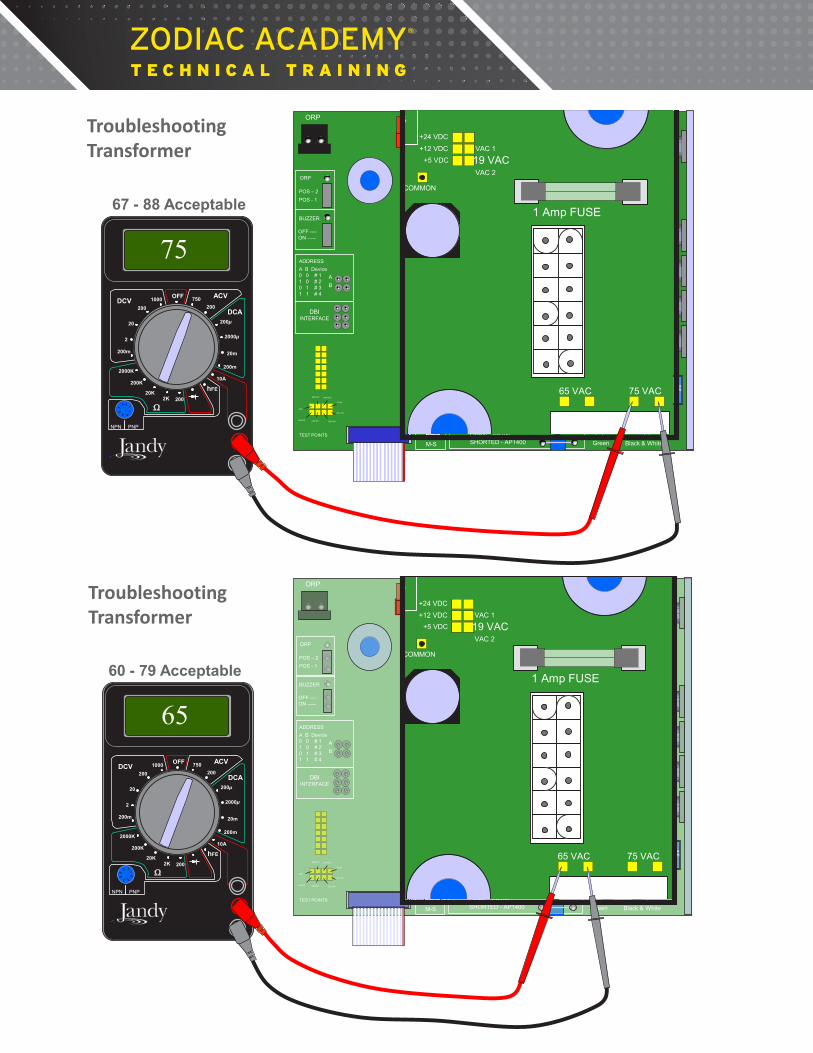
67 - 88 Acceptable
Troubleshooting Transformer
ORP
OPEN - AP700 SHORTED - AP1400 M-S
15
Green Black & White
(+) (-)
ORP
POS – 2
POS - 1
BUZZER
OFF ---- ON -----
ADDRESS A B Device 0 0 # 1 1 0 # 2 0 1 # 3 1 1 # 4
A
B
DBI INTERFACE
Mechanical Sensor
ENB DIS
FLOW SENSOR
H - Temp
R - Temp Salinity
1 Amp FUSE
Salinity = 2.8 R Temp = 75 H Temp = 91
TEST POINTS
19 VAC VAC 1
VAC 2
120 mVDC
65 VAC 75 VAC
15 A
mp
FUS
E
+24 VDC
+5 VDC
COMMON
GROUND HEATER RESTING
CELL ON
FLOW
SERVICE
ORP
LOW SALT
+12 VDC
ORP
OPEN - AP700SHORTED - AP1400 M-S
15
Green Black & White
(+) (-)
ORP
POS – 2
POS - 1
BUZZER
OFF ----ON -----
ADDRESSA B Device0 0 # 11 0 # 20 1 # 31 1 # 4
A
B
DBIINTERFACE
Mechanical Sensor
ENBDIS
FLOW SENSOR
H - Temp
R - Temp Salinity
1 Amp FUSE
Salinity = 2.8R Temp = 75H Temp = 91
TEST POINTS
19 VACVAC 1
VAC 2
120 mVDC
65 VAC 75 VAC
15 A
mp
FUS
E
+24 VDC
+12 VDC+5 VDC
COMMON
GROUNDHEATER RESTING
CELL ON
FLOWLOW SALTSERVICE
ORP
ORP
OPEN - AP700SHORTED - AP1400 M-S
15
Green Black & White
(+) (-)
ORP
POS – 2
POS - 1
BUZZER
OFF ----ON -----
ADDRESSA B Device0 0 # 11 0 # 20 1 # 31 1 # 4
A
B
DBIINTERFACE
Mechanical Sensor
ENBDIS
FLOW SENSOR
H - Temp
R - Temp Salinity
1 Amp FUSE
Salinity = 2.8R Temp = 75H Temp = 91
TEST POINTS
19 VACVAC 1
VAC 2
120 mVDC
65 VAC 75 VAC
15 A
mp
FUS
E
+24 VDC
+12 VDC+5 VDC
COMMON
GROUNDHEATER RESTING
CELL ON
FLOWLOW SALTSERVICE
ORP
ORP
OPEN - AP700SHORTED - AP1400 M-S
15
Green Black & White
(+) (-)
ORP
POS – 2
POS - 1
BUZZER
OFF ----ON -----
ADDRESSA B Device0 0 # 11 0 # 20 1 # 31 1 # 4
A
B
DBIINTERFACE
Mechanical Sensor
ENBDIS
FLOW SENSOR
H - Temp
R - Temp Salinity
1 Amp FUSE
Salinity = 2.8R Temp = 75H Temp = 91
TEST POINTS
19 VACVAC 1
VAC 2
120 mVDC
65 VAC 75 VAC
15 A
mp
FUS
E
+24 VDC
+12 VDC+5 VDC
COMMON
GROUNDHEATER RESTING
CELL ON
FLOWLOW SALTSERVICE
ORP
DCV
W
2000K
200K
20K 2K
hFE
2
20
200 1000
200 750
PNP NPN
OFF
200m
DCA
20m
200m
10A
200
ACV
200µ
2000µ
65
60 - 79 Acceptable
Troubleshooting Transformer

ORP
OPEN - AP700 SHORTED - AP1400 M-S
15
Green Black & White
(+) (-)
ORP
POS – 2
POS - 1
BUZZER
OFF ---- ON -----
ADDRESS A B Device 0 0 # 1 1 0 # 2 0 1 # 3 1 1 # 4
A
B
DBI INTERFACE
Mechanical Sensor
ENB DIS
FLOW SENSOR
H - Temp
R - Temp Salinity
1 Amp FUSE
Salinity = 2.8 R Temp = 75 H Temp = 91
TEST POINTS
19 VAC VAC 1
VAC 2
120 mVDC
65 VAC 75 VAC
15 A
mp
FUS
E
+24 VDC
+5 VDC
COMMON
GROUND HEATER RESTING
CELL ON
FLOW
SERVICE
ORP
LOW SALT
+12 VDC
ORP
OPEN - AP700SHORTED - AP1400 M-S
15
Green Black & White
(+) (-)
ORP
POS – 2
POS - 1
BUZZER
OFF ----ON -----
ADDRESSA B Device0 0 # 11 0 # 20 1 # 31 1 # 4
A
B
DBIINTERFACE
Mechanical Sensor
ENBDIS
FLOW SENSOR
H - Temp
R - Temp Salinity
1 Amp FUSE
Salinity = 2.8R Temp = 75H Temp = 91
TEST POINTS
19 VACVAC 1
VAC 2
120 mVDC
65 VAC 75 VAC
15 A
mp
FUS
E
+24 VDC
+12 VDC+5 VDC
COMMON
GROUNDHEATER RESTING
CELL ON
FLOWLOW SALTSERVICE
ORP
ORP
OPEN - AP700SHORTED - AP1400 M-S
15
Green Black & White
(+) (-)
ORP
POS – 2
POS - 1
BUZZER
OFF ----ON -----
ADDRESSA B Device0 0 # 11 0 # 20 1 # 31 1 # 4
A
B
DBIINTERFACE
Mechanical Sensor
ENBDIS
FLOW SENSOR
H - Temp
R - Temp Salinity
1 Amp FUSE
Salinity = 2.8R Temp = 75H Temp = 91
TEST POINTS
19 VACVAC 1
VAC 2
120 mVDC
65 VAC 75 VAC
15 A
mp
FUS
E
+24 VDC
+12 VDC+5 VDC
COMMON
GROUNDHEATER RESTING
CELL ON
FLOWLOW SALTSERVICE
ORP
ORP
OPEN - AP700SHORTED - AP1400 M-S
15
Green Black & White
(+) (-)
ORP
POS – 2
POS - 1
BUZZER
OFF ----ON -----
ADDRESSA B Device0 0 # 11 0 # 20 1 # 31 1 # 4
A
B
DBIINTERFACE
Mechanical Sensor
ENBDIS
FLOW SENSOR
H - Temp
R - Temp Salinity
1 Amp FUSE
Salinity = 2.8R Temp = 75H Temp = 91
TEST POINTS
19 VACVAC 1
VAC 2
120 mVDC
65 VAC 75 VAC
15 A
mp
FUS
E
+24 VDC
+12 VDC+5 VDC
COMMON
GROUNDHEATER RESTING
CELL ON
FLOWLOW SALTSERVICE
ORP
DCV
W
2000K
200K
20K 2K
hFE
2
20
200 1000
200 750
PNP NPN
OFF
200m
DCA
20m
200m
10A
200
ACV
200µ
2000µ
19
17 - 24 Acceptable
*Check 1 Amp Fuse Before Replacing Transformer
Troubleshooting Transformer
25
Notes:

ORP
OPEN - AP700 SHORTED - AP1400 M-S
15
Green Black & White
(+) (-)
ORP
POS – 2
POS - 1
BUZZER
OFF ---- ON -----
ADDRESS A B Device 0 0 # 1 1 0 # 2 0 1 # 3 1 1 # 4
A
B
DBI INTERFACE
Mechanical Sensor
ENB DIS
FLOW SENSOR
H - Temp
R - Temp Salinity
1 Amp FUSE
Salinity = 2.8 R Temp = 75 H Temp = 91
TEST POINTS
19 VAC VAC 1
VAC 2
120 mVDC
65 VAC 75 VAC
15 A
mp
FUS
E
+24 VDC
+5 VDC
COMMON
GROUND HEATER RESTING
CELL ON
FLOW
SERVICE
ORP
LOW SALT
+12 VDC
DCV
W
2000K
200K
20K 2K
hFE
2
20
200 1000
200 750
PNP NPN
OFF
200m
DCA
20m
200m
10A
200
ACV
200µ
2000µ
ORP
OPEN - AP700SHORTED - AP1400 M-S
15
Green Black & White
(+) (-)
ORP
POS – 2
POS - 1
BUZZER
OFF ----ON -----
ADDRESSA B Device0 0 # 11 0 # 20 1 # 31 1 # 4
A
B
DBIINTERFACE
Mechanical Sensor
ENBDIS
FLOW SENSOR
H - Temp
R - Temp Salinity
1 Amp FUSE
Salinity = 2.8R Temp = 75H Temp = 91
TEST POINTS
19 VACVAC 1
VAC 2
120 mVDC
65 VAC 75 VAC
15 A
mp
FUS
E
+24 VDC
+12 VDC+5 VDC
COMMON
GROUNDHEATER RESTING
CELL ON
FLOWLOW SALTSERVICE
ORP
ORP
OPEN - AP700SHORTED - AP1400 M-S
15
Green Black & White
(+) (-)
ORP
POS – 2
POS - 1
BUZZER
OFF ----ON -----
ADDRESSA B Device0 0 # 11 0 # 20 1 # 31 1 # 4
A
B
DBIINTERFACE
Mechanical Sensor
ENBDIS
FLOW SENSOR
H - Temp
R - Temp Salinity
1 Amp FUSE
Salinity = 2.8R Temp = 75H Temp = 91
TEST POINTS
19 VACVAC 1
VAC 2
120 mVDC
65 VAC 75 VAC
15 A
mp
FUS
E
+24 VDC
+12 VDC+5 VDC
COMMON
GROUNDHEATER RESTING
CELL ON
FLOWLOW SALTSERVICE
ORP
12
11.8 – 12.2 Acceptable
Troubleshooting V DC Conversion
ORP
OPEN - AP700 SHORTED - AP1400 M-S
15
Green Black & White
(+) (-)
ORP
POS – 2
POS - 1
BUZZER
OFF ---- ON -----
ADDRESS A B Device 0 0 # 1 1 0 # 2 0 1 # 3 1 1 # 4
A
B
DBI INTERFACE
Mechanical Sensor
ENB DIS
FLOW SENSOR
H - Temp
R - Temp Salinity
1 Amp FUSE
Salinity = 2.8 R Temp = 75 H Temp = 91
TEST POINTS
19 VAC VAC 1
VAC 2
120 mVDC
65 VAC 75 VAC
15 A
mp
FUS
E
+24 VDC
+5 VDC
COMMON
GROUND HEATER RESTING
CELL ON
FLOW
SERVICE
ORP
LOW SALT
+12 VDC
DCV
W
2000K
200K
20K 2K
hFE
2
20
200 1000
200 750
PNP NPN
OFF
200m
DCA
20m
200m
10A
200
ACV
200µ
2000µ
ORP
OPEN - AP700SHORTED - AP1400 M-S
15
Green Black & White
(+) (-)
ORP
POS – 2
POS - 1
BUZZER
OFF ----ON -----
ADDRESSA B Device0 0 # 11 0 # 20 1 # 31 1 # 4
A
B
DBIINTERFACE
Mechanical Sensor
ENBDIS
FLOW SENSOR
H - Temp
R - Temp Salinity
1 Amp FUSE
Salinity = 2.8R Temp = 75H Temp = 91
TEST POINTS
19 VACVAC 1
VAC 2
120 mVDC
65 VAC 75 VAC
15 A
mp
FUS
E
+24 VDC
+12 VDC+5 VDC
COMMON
GROUNDHEATER RESTING
CELL ON
FLOWLOW SALTSERVICE
ORP
ORP
OPEN - AP700SHORTED - AP1400 M-S
15
Green Black & White
(+) (-)
ORP
POS – 2
POS - 1
BUZZER
OFF ----ON -----
ADDRESSA B Device0 0 # 11 0 # 20 1 # 31 1 # 4
A
B
DBIINTERFACE
Mechanical Sensor
ENBDIS
FLOW SENSOR
H - Temp
R - Temp Salinity
1 Amp FUSE
Salinity = 2.8R Temp = 75H Temp = 91
TEST POINTS
19 VACVAC 1
VAC 2
120 mVDC
65 VAC 75 VAC
15 A
mp
FUS
E
+24 VDC
+12 VDC+5 VDC
COMMON
GROUNDHEATER RESTING
CELL ON
FLOWLOW SALTSERVICE
ORP
ORP
OPEN - AP700SHORTED - AP1400 M-S
15
Green Black & White
(+) (-)
ORP
POS – 2
POS - 1
BUZZER
OFF ----ON -----
ADDRESSA B Device0 0 # 11 0 # 20 1 # 31 1 # 4
A
B
DBIINTERFACE
Mechanical Sensor
ENBDIS
FLOW SENSOR
H - Temp
R - Temp Salinity
1 Amp FUSE
Salinity = 2.8R Temp = 75H Temp = 91
TEST POINTS
19 VACVAC 1
VAC 2
120 mVDC
65 VAC 75 VAC
15 A
mp
FUS
E
+24 VDC
+12 VDC+5 VDC
COMMON
GROUNDHEATER RESTING
CELL ON
FLOWLOW SALTSERVICE
ORP
5
4.8 – 5.2 Acceptable
Troubleshooting V DC Conversion
ORP
OPEN - AP700 SHORTED - AP1400 M-S
15
Green Black & White (+) (-)
ORP
POS – 2
POS - 1
BUZZER
OFF ---- ON -----
ADDRESS A B Device 0 0 # 1 1 0 # 2 0 1 # 3 1 1 # 4
A
B
DBI INTERFACE
Mechanical Sensor
ENB DIS
FLOW SENSOR
H - Temp
R - Temp Salinity
1 Amp FUSE
Salinity = 2.8 R Temp = 75 H Temp = 91
TEST POINTS
19 VAC VAC 1
VAC 2
120 mVDC
65 VAC 75 VAC
15 A
mp
FUS
E
+24 VDC
+5 VDC
COMMON
GROUND HEATER RESTING
CELL ON
FLOW
SERVICE
ORP
LOW SALT
+12 VDC
A B
C
?
D
?
ORP
OPEN - AP700SHORTED - AP1400 M-S
15
Green Black & White
(+) (-)
ORP
POS – 2
POS - 1
BUZZER
OFF ----ON -----
ADDRESSA B Device0 0 # 11 0 # 20 1 # 31 1 # 4
A
B
DBIINTERFACE
Mechanical Sensor
ENBDIS
FLOW SENSOR
H - Temp
R - Temp Salinity
1 Amp FUSE
Salinity = 2.8R Temp = 75H Temp = 91
TEST POINTS
19 VACVAC 1
VAC 2
120 mVDC
65 VAC 75 VAC
15 A
mp
FUS
E
+24 VDC
+12 VDC+5 VDC
COMMON
GROUNDHEATER RESTING
CELL ON
FLOWLOW SALTSERVICE
ORP
ORP
OPEN - AP700SHORTED - AP1400 M-S
15
Green Black & White
(+) (-)
ORP
POS – 2
POS - 1
BUZZER
OFF ----ON -----
ADDRESSA B Device0 0 # 11 0 # 20 1 # 31 1 # 4
A
B
DBIINTERFACE
Mechanical Sensor
ENBDIS
FLOW SENSOR
H - Temp
R - Temp Salinity
1 Amp FUSE
Salinity = 2.8R Temp = 75H Temp = 91
TEST POINTS
19 VACVAC 1
VAC 2
120 mVDC
65 VAC 75 VAC
15 A
mp
FUS
E
+24 VDC
+12 VDC+5 VDC
COMMON
GROUNDHEATER RESTING
CELL ON
FLOWLOW SALTSERVICE
ORP
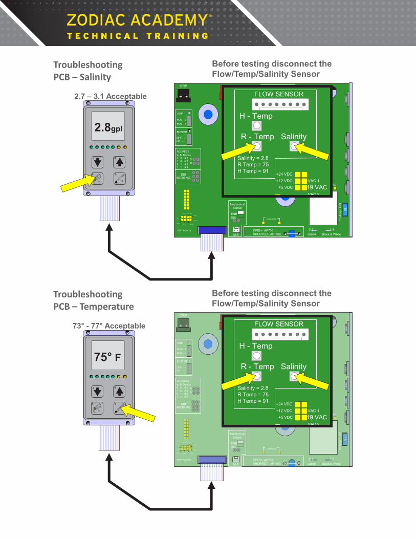
2.8gpl
Before testing disconnect the Flow/Temp/Salinity Sensor
2.7 – 3.1 Acceptable
Troubleshooting PCB – Salinity
A B
C
?
D
?
ORP
OPEN - AP700 SHORTED - AP1400 M-S
15
Green Black & White (+) (-)
ORP
POS – 2
POS - 1
BUZZER
OFF ---- ON -----
ADDRESS A B Device 0 0 # 1 1 0 # 2 0 1 # 3 1 1 # 4
A
B
DBI INTERFACE
Mechanical Sensor
ENB DIS
FLOW SENSOR
H - Temp
R - Temp Salinity
1 Amp FUSE
Salinity = 2.8 R Temp = 75 H Temp = 91
TEST POINTS
19 VAC VAC 1
VAC 2
120 mVDC
65 VAC 75 VAC
15 A
mp
FUS
E
+24 VDC
+5 VDC
COMMON
GROUND HEATER RESTING
CELL ON
FLOW
SERVICE
ORP
LOW SALT
+12 VDC
ORP
OPEN - AP700SHORTED - AP1400 M-S
15
Green Black & White
(+) (-)
ORP
POS – 2
POS - 1
BUZZER
OFF ----ON -----
ADDRESSA B Device0 0 # 11 0 # 20 1 # 31 1 # 4
A
B
DBIINTERFACE
Mechanical Sensor
ENBDIS
FLOW SENSOR
H - Temp
R - Temp Salinity
1 Amp FUSE
Salinity = 2.8R Temp = 75H Temp = 91
TEST POINTS
19 VACVAC 1
VAC 2
120 mVDC
65 VAC 75 VAC
15 A
mp
FUS
E
+24 VDC
+12 VDC+5 VDC
COMMON
GROUNDHEATER RESTING
CELL ON
FLOWLOW SALTSERVICE
ORP
ORP
OPEN - AP700SHORTED - AP1400 M-S
15
Green Black & White
(+) (-)
ORP
POS – 2
POS - 1
BUZZER
OFF ----ON -----
ADDRESSA B Device0 0 # 11 0 # 20 1 # 31 1 # 4
A
B
DBIINTERFACE
Mechanical Sensor
ENBDIS
FLOW SENSOR
H - Temp
R - Temp Salinity
1 Amp FUSE
Salinity = 2.8R Temp = 75H Temp = 91
TEST POINTS
19 VACVAC 1
VAC 2
120 mVDC
65 VAC 75 VAC
15 A
mp
FUS
E
+24 VDC
+12 VDC+5 VDC
COMMON
GROUNDHEATER RESTING
CELL ON
FLOWLOW SALTSERVICE
ORP
75° F
73° - 77° Acceptable
Before testing disconnect the Flow/Temp/Salinity Sensor
Troubleshooting PCB – Temperature
A B
C
?
D
?
ORP
OPEN - AP700 SHORTED - AP1400 M-S
15
Green Black & White (+) (-)
ORP
POS – 2
POS - 1
BUZZER
OFF ---- ON -----
ADDRESS A B Device 0 0 # 1 1 0 # 2 0 1 # 3 1 1 # 4
A
B
DBI INTERFACE
Mechanical Sensor
ENB DIS
FLOW SENSOR
H - Temp
R - Temp Salinity
1 Amp FUSE
Salinity = 2.8 R Temp = 75 H Temp = 91
TEST POINTS
19 VAC VAC 1
VAC 2
120 mVDC
65 VAC 75 VAC
15 A
mp
FUS
E
+24 VDC
+5 VDC
COMMON
GROUND HEATER RESTING
CELL ON
FLOW
SERVICE
ORP
LOW SALT
+12 VDC
ORP
OPEN - AP700SHORTED - AP1400 M-S
15
Green Black & White
(+) (-)
ORP
POS – 2
POS - 1
BUZZER
OFF ----ON -----
ADDRESSA B Device0 0 # 11 0 # 20 1 # 31 1 # 4
A
B
DBIINTERFACE
Mechanical Sensor
ENBDIS
FLOW SENSOR
H - Temp
R - Temp Salinity
1 Amp FUSE
Salinity = 2.8R Temp = 75H Temp = 91
TEST POINTS
19 VACVAC 1
VAC 2
120 mVDC
65 VAC 75 VAC
15 A
mp
FUS
E
+24 VDC
+12 VDC+5 VDC
COMMON
GROUNDHEATER RESTING
CELL ON
FLOWLOW SALTSERVICE
ORP
ORP
OPEN - AP700SHORTED - AP1400 M-S
15
Green Black & White
(+) (-)
ORP
POS – 2
POS - 1
BUZZER
OFF ----ON -----
ADDRESSA B Device0 0 # 11 0 # 20 1 # 31 1 # 4
A
B
DBIINTERFACE
Mechanical Sensor
ENBDIS
FLOW SENSOR
H - Temp
R - Temp Salinity
1 Amp FUSE
Salinity = 2.8R Temp = 75H Temp = 91
TEST POINTS
19 VACVAC 1
VAC 2
120 mVDC
65 VAC 75 VAC
15 A
mp
FUS
E
+24 VDC
+12 VDC+5 VDC
COMMON
GROUNDHEATER RESTING
CELL ON
FLOWLOW SALTSERVICE
ORP
ORP
OPEN - AP700SHORTED - AP1400 M-S
15
Green Black & White
(+) (-)
ORP
POS – 2
POS - 1
BUZZER
OFF ----ON -----
ADDRESSA B Device0 0 # 11 0 # 20 1 # 31 1 # 4
A
B
DBIINTERFACE
Mechanical Sensor
ENBDIS
FLOW SENSOR
H - Temp
R - Temp Salinity
1 Amp FUSE
Salinity = 2.8R Temp = 75H Temp = 91
TEST POINTS
19 VACVAC 1
VAC 2
120 mVDC
65 VAC 75 VAC
15 A
mp
FUS
E
+24 VDC
+12 VDC+5 VDC
COMMON
GROUNDHEATER RESTING
CELL ON
FLOWLOW SALTSERVICE
ORP
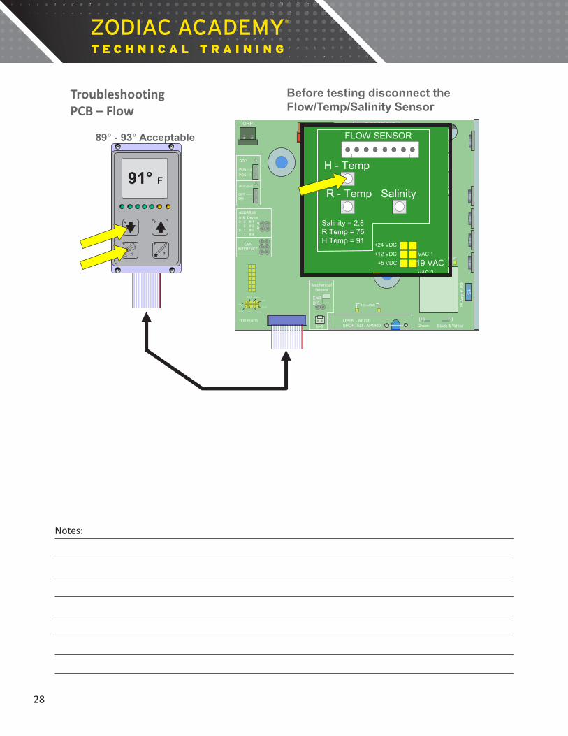
91° F
89° - 93° Acceptable
Before testing disconnect the Flow/Temp/Salinity Sensor
Troubleshooting PCB – Flow
28
Notes:
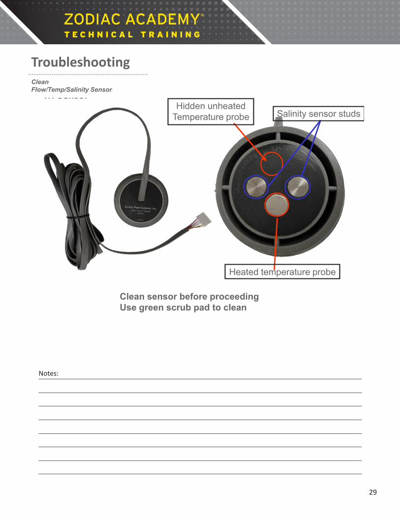
Hidden unheated Temperature probe Salinity sensor studs
Clean sensor before proceeding Use green scrub pad to clean
Heated temperature probe
Troubleshooting Tri-Sensor
Troubleshooting Clean Flow/Temp/Salinity Sensor
29
Notes:

• Add 1 part muriatic acid to 4 parts water. • When bubbling quits the cell is clean. • Rinse thoroughly after cleaning. • Do not leave the cell in acid for more than 30 minutes.
Troubleshooting Cell Cleaning
Note: Do not use a metal knife or screw driver to dislodge debris. Either could scratch the ruthenium coating.
Troubleshooting Clean Cell
• Add 1 part muriatic acid to 4 parts water. • When bubbling quits the cell is clean. • Rinse thoroughly after cleaning. • Do not leave the cell in acid for more than 30 minutes.
Troubleshooting Cell Cleaning
Note: Do not use a metal knife or screw driver to dislodge debris. Either could scratch the ruthenium coating.
30
Notes:

Troubleshooting Cell Voltage
ORP
OPEN - AP700 SHORTED - AP1400 M-S
15
Green Black & White
(+) (-)
ORP
POS – 2
POS - 1
BUZZER
OFF ---- ON -----
ADDRESS A B Device 0 0 # 1 1 0 # 2 0 1 # 3 1 1 # 4
A
B
DBI INTERFACE
Mechanical Sensor
ENB DIS
FLOW SENSOR
H - Temp
R - Temp Salinity
1 Amp FUSE
Salinity = 2.8 R Temp = 75 H Temp = 91
TEST POINTS
19 VAC VAC 1
VAC 2
120 mVDC
65 VAC 75 VAC
15 A
mp
FUS
E
+24 VDC
+5 VDC
COMMON
GROUND HEATER RESTING
CELL ON
FLOW
SERVICE
ORP
LOW SALT
+12 VDC
DCV
W
2000K
200K
20K 2K
hFE
2
20
200 1000
200 750
PNP NPN
OFF
200m
DCA
20m
200m
10A
200
ACV
200µ
2000µ
25
Rev A Cell 22 – 28 Acceptable
Rev A 22 to 28 VDC Rev B or Newer Cell
29 to 32 VDC
30
Troubleshooting Cell Voltage
Rev A 22 to 28 VDC Rev B or Newer Cell
29 to 32 VDC

ORP
OPEN - AP700 SHORTED - AP1400 M-S
15
Green Black & White
(+) (-)
ORP
POS – 2
POS - 1
BUZZER
OFF ---- ON -----
ADDRESS A B Device 0 0 # 1 1 0 # 2 0 1 # 3 1 1 # 4
A
B
DBI INTERFACE
Mechanical Sensor
ENB DIS
FLOW SENSOR
H - Temp
R - Temp Salinity
1 Amp FUSE
Salinity = 2.8 R Temp = 75 H Temp = 91
TEST POINTS
19 VAC VAC 1
VAC 2
120 mVDC
65 VAC 75 VAC
15 A
mp
FUS
E
+24 VDC
+5 VDC
COMMON
GROUND HEATER RESTING
CELL ON
FLOW
SERVICE
ORP
LOW SALT
+12 VDC
DCV
W
2000K
200K
20K 2K
hFE
2
20
200 1000
200 750
PNP NPN
OFF
200m
DCA
20m
200m
10A
200
ACV
200µ
2000µ
125
100 – 145 millivolts DC Acceptable
ORP
OPEN - AP700SHORTED - AP1400 M-S
15
Green Black & White
(+) (-)
ORP
POS – 2
POS - 1
BUZZER
OFF ----ON -----
ADDRESSA B Device0 0 # 11 0 # 20 1 # 31 1 # 4
A
B
DBIINTERFACE
Mechanical Sensor
ENBDIS
FLOW SENSOR
H - Temp
R - Temp Salinity
1 Amp FUSE
Salinity = 2.8R Temp = 75H Temp = 91
TEST POINTS
19 VACVAC 1
VAC 2
120 mVDC
65 VAC 75 VAC
15 A
mp
FUS
E
+24 VDC
+12 VDC+5 VDC
COMMON
GROUNDHEATER RESTING
CELL ON
FLOWLOW SALTSERVICE
ORP
ORP
OPEN - AP700SHORTED - AP1400 M-S
15
Green Black & White
(+) (-)
ORP
POS – 2
POS - 1
BUZZER
OFF ----ON -----
ADDRESSA B Device0 0 # 11 0 # 20 1 # 31 1 # 4
A
B
DBIINTERFACE
Mechanical Sensor
ENBDIS
FLOW SENSOR
H - Temp
R - Temp Salinity
1 Amp FUSE
Salinity = 2.8R Temp = 75H Temp = 91
TEST POINTS
19 VACVAC 1
VAC 2
120 mVDC
65 VAC 75 VAC
15 A
mp
FUS
E
+24 VDC
+12 VDC+5 VDC
COMMON
GROUNDHEATER RESTING
CELL ON
FLOWLOW SALTSERVICE
ORP
Troubleshooting Cell Current
32
Notes:

172 – Flow sensor service - clean sensor, check for damage and replace if necessary.
CELL ON
CELL RESTING
FLOW
CELL REVERSING
ADD SALT
SERVICE
CHLORINE PRODUCTION RATE
Salinity Pool Temp
-Boost-
POWER ON
A B
C
?
D
?
172
Troubleshooting Service Codes
180 – Heated sensor element not heating.
CELL ON
CELL RESTING
FLOW
CELL REVERSING
ADD SALT
SERVICE
CHLORINE PRODUCTION RATE
Salinity Pool
Temp -Boost-
POWER ON
A B
C
?
D
?
Troubleshooting Service Codes
180 180 – Heated sensor element not heating.
CELL ON
CELL RESTING
FLOW
CELL REVERSING
ADD SALT
SERVICE
CHLORINE PRODUCTION RATE
Salinity Pool
Temp -Boost-
POWER ON
A B
C
?
D
?
Troubleshooting Service Codes
180

120 - Low cell current in forward direction - check DC cord, clean cell if necessary or replace cell. 121 - Low cell current in reverse direction, same as 120 above. 123 - Low to no current at cell - check DC cord, clean cell or replace if necessary. 124 - High current indicated at the cell - this usually means a bad PIB. 125 - Cell needs to be cleaned or replaced. 126 - Low current in forward direction and VAC input voltage below 100/200 VAC - check input voltage, transformer and PIB voltages. 127 -Low current in reverse direction and VAC input voltage below 100/200 VAC - check input voltage, transformer and PIB voltages. 144 - Low Salinity (below 2.0 gpl) - indicates the pool needs salt added. 145 - High Salinity (above 4.1 gpl or 6.1 on unit Rev 01220A15) - indicates pool needs to be diluted. 170 - PIB service condition indicated and is usually caused by low incoming AC voltage - check transformer voltages – Can also be cause by faulty sensor. 171 - PIB service condition - indicates board needs to be replaced. 172 – Flow sensor service - clean sensor, check for damage and replace if necessary. 173 - Low VAC input voltage and on-board power supply is not regulated - make sure unit is wired with the proper voltage. 174 - Pool temperature is too high for operation of AquaPure® (i.e. > 108°F)(REV 01220A15,and newer > 116°F). 175 - Flow sensor air lock condition or very low salinity.
Level 1 Error Codes
180 - Heated sensor element not heating (generates 172 code) 181 - Flow sensor temperature sensor failure (generates 172 code – Flow sensor service) 182 - Salinity Sensor sees less than 0.2 gpl of salt, either no salt in pool or sensor air locked (generates 175 code – Flow sensor air lock) 183 to 186 - flow salinity sensor temperature probe error codes. They will all generate 172 codes which indicate flow sensor service is required. 187 - PIB power supply either too low or too high (generates 173 - Low input voltage code if Level II code 188 is present) (generates 170 code if 188 is not present). 188 - VAC input voltage is too low (generates 173 code if Level II code 187 is present) 189 - Relay not conducting in the forward direction (generates 171 code - PIB service) 190 - Relay not conducting in the reverse direction (generates 171 code - PIB service) 191- High cell current (at upper limit of A/D converter) and cell voltage below 19V (generates 170 code PIB service) 192 - High cell current and cell voltage below 19V (generates 171 code – PIB service). 193 - Measured significant cell current when SCRs were turned off (generates 170 code – PIB service). 194 - Cell Current is 85% lower than desired and cell voltage above 19V (generates 125 code - Cell dirty or needs replacement). 195 - Salinity invalid due to out of range measurements caused by PIB error (generates 170 code – PIB service).
Level 2 Error Codes

Notes: