Embed Size (px)
Citation preview

English Deutsch EspañolItalianoFrançais
Air Cooled Water Chillers and Heat PumpsRefroidisseurs de liquide à condensation par air et pompes à chaleur air-eauLuftgekühlte Flüssigkeitskühler und WärmepumpenRefrigeratori d'Acqua e Pompe di Calore Raffreddati ad AriaEnfriadores de Agua y Bomba de Calor Condensadas con Aire
Installation and maintenance manualManuel d'installation et de maintenanceInstallations- und WartungshandbuchManuale di installazione e di manutenzioneManual de instalación y de mantenimiento
AQL/AQH 20-75AQC 40-75
IOM AQ410-N.3GBPart number / Code / Code / Codice / Código : 035B09040-000DSupersedes / Annule et remplace / Annulliert und ersetzt / Annulla e sostituisce / Anula y sustituye : 035B09040-000CNotified Body / Organisme Notifié / Benannte Zertifizierungsstelle / Organismo Notificato / Organismo Notificado N°. 1115
20
77 kW
20
86 kW
ISO 9001 certified management system

II
1
Engl
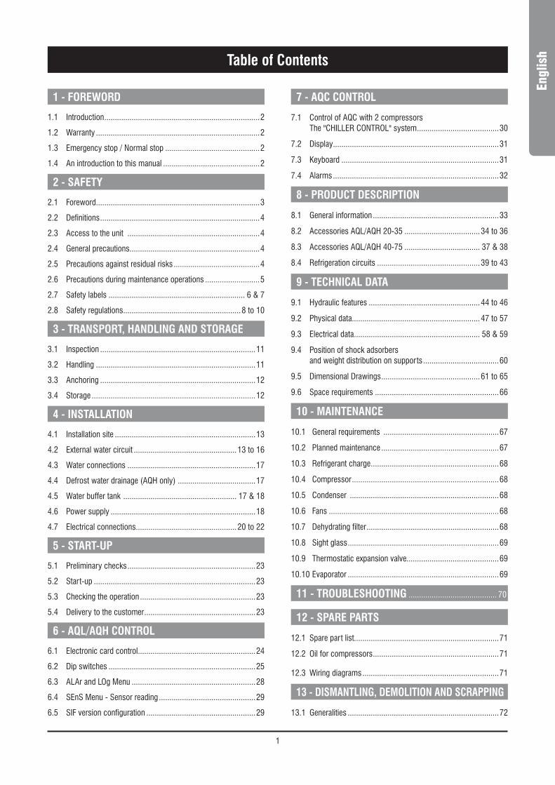
ishTable of Contents
1 - FOREWORD
1.1 Introduction ..........................................................................2
1.2 Warranty ..............................................................................2
1.3 Emergency stop / Normal stop .............................................2
1.4 An introduction to this manual ..............................................2
2 - SAFETY
2.1 Foreword ..............................................................................3
2.2 Definitions ............................................................................4
2.3 Access to the unit ...............................................................4
2.4 General precautions..............................................................4
2.5 Precautions against residual risks .........................................4
2.6 Precautions during maintenance operations ..........................5
2.7 Safety labels ................................................................. 6 & 7
2.8 Safety regulations ........................................................8 to 10
3 - TRANSPORT, HANDLING AND STORAGE
3.1 Inspection ..........................................................................11
3.2 Handling ............................................................................11
3.3 Anchoring ..........................................................................12
3.4 Storage ..............................................................................12
4 - INSTALLATION
4.1 Installation site ...................................................................13
4.2 External water circuit .................................................13 to 16
4.3 Water connections .............................................................17
4.4 Defrost water drainage (AQH only) .....................................17
4.5 Water buffer tank ...................................................... 17 & 18
4.6 Power supply .....................................................................18
4.7 Electrical connections................................................20 to 22
5 - START-UP
5.1 Preliminary checks .............................................................23
5.2 Start-up .............................................................................23
5.3 Checking the operation .......................................................23
5.4 Delivery to the customer .....................................................23
6 - AQL/AQH CONTROL
6.1 Electronic card control ........................................................24
6.2 Dip switches ......................................................................25
6.3 ALAr and LOg Menu ...........................................................28
6.4 SEnS Menu - Sensor reading ..............................................29
6.5 SIF version configuration ....................................................29
7 - AQC CONTROL
7.1 Control of AQC with 2 compressors The "CHILLER CONTROL" system .......................................30
7.2 Display ...............................................................................31
7.3 Keyboard ...........................................................................31
7.4 Alarms ...............................................................................32
8 - PRODUCT DESCRIPTION
8.1 General information ............................................................33
8.2 Accessories AQL/AQH 20-35 ....................................34 to 36
8.3 Accessories AQL/AQH 40-75 .................................... 37 & 38
8.4 Refrigeration circuits .................................................39 to 43
9 - TECHNICAL DATA
9.1 Hydraulic features .....................................................44 to 46
9.2 Physical data.............................................................47 to 57
9.3 Electrical data ............................................................ 58 & 59
9.4 Position of shock adsorbers and weight distribution on supports ....................................60
9.5 Dimensional Drawings ...............................................61 to 65
9.6 Space requirements ...........................................................66
10 - MAINTENANCE
10.1 General requirements .......................................................67
10.2 Planned maintenance ........................................................67
10.3 Refrigerant charge .............................................................68
10.4 Compressor ......................................................................68
10.5 Condenser .......................................................................68
10.6 Fans .................................................................................68
10.7 Dehydrating filter ...............................................................68
10.8 Sight glass ........................................................................69
10.9 Thermostatic expansion valve............................................69
10.10 Evaporator ........................................................................69
11 - TROUBLESHOOTING .......................................... 70
12 - SPARE PARTS
12.1 Spare part list.....................................................................71
12.2 Oil for compressors ............................................................71
12.3 Wiring diagrams .................................................................71
13 - DISMANTLING, DEMOLITION AND SCRAPPING
13.1 Generalities ........................................................................72

2
1 - Foreword
1.1 Introduction
Units, manufactured to state-of-the-art design and implementation standards, ensure top performance, reliability and fitness to any type of air-conditioning systems.
These units are designed for cooling water or glycoled water (and for water heating in heat pump models) and are unfit for any purposes other than those specified in this manual.
This manual includes all the information required for a proper installation of the units, as well as the relevant operating and maintenance instructions.
It is therefore recommended to read this manual carefully before installation or any operation on the machine. The chiller installation and maintenance must be carried out by skilled personnel only (where possible, by one of Authorised Service Centers).
The manufacturer may not be held liable for any damage to people or property caused by improper installation, start-up and/or improper use of the unit and/or failure to implement the procedures and instructions included in this manual.
1.2 Warranty
These units are delivered complete, tested and ready for being operated. Any form of warranty will become null and void in the event that the appliance is modified without manufacturer’s preliminary written authorisation.
This warranty shall apply providing that the installation instructions have been complied with (either issued by manufacturer, or deriving from the current practice), and the Form 1 (“Start-up”) has been filled-in and mailed to manufacturer (attn. After-Sales Service).
In order for this warranty to be valid, the following conditions shall be met :
n The machine must be operated only by skilled personnel from Authorised After-Sales Service.
n Maintenance must be performed only by skilled personnel - from one of Authorised After-Sales Centers.
n Use only original spare parts.
n Carry out all the planned maintenance provided for by this manual in a timely and proper way.
Failure to comply with any of these conditions will automatically void the warranty.
1.3 Emergency stop / Normal stop
The emergency stop of the unit can be enabled using the master switch on the control panel (move down the lever).
For a normal stop, press the relevant push-buttons.
To restart the appliance, follow the procedure detailed in this manual.
1.4 An introduction to the manual
For safety reasons, it is imperative to follow the instructions given in this manual. In case of any damage caused by non-compliance with these instructions, the warranty will immediately become null and void.
Conventions used throughout the manual :
DANGER
The DANGER sign recalls your attention to a certain procedure or practice which, if not followed, may result in serious damage to people and property.
WARNING
The WARNING sign precedes those procedures that, if not followed, may result in serious damage to the appliance.
NOTE
The NOTE contain important observations.
USEFUL TIPS
The USEFUL TIPS provide valuable information that optimises the efficiency of the appliance.
This manual and its contents, as well as the documentation which accompanies the unit, are and remain the property of manufacturer, which reserves any and all rights thereon. This manual may not be copied, in whole or in part, without manufacturer’s written authorization.
3
Engl
ish2 - Safety
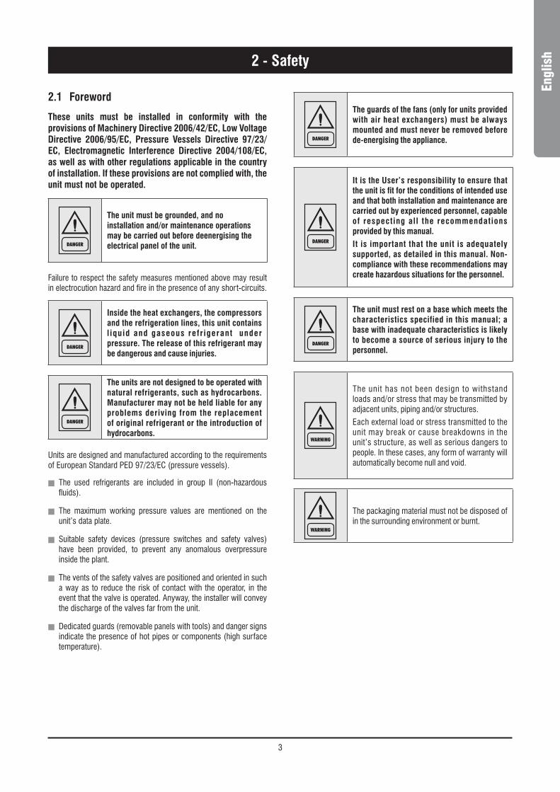
2.1 Foreword
These units must be installed in conformity with the provisions of Machinery Directive 2006/42/EC, Low Voltage Directive 2006/95/EC, Pressure Vessels Directive 97/23/EC, Electromagnetic Interference Directive 2004/108/EC, as well as with other regulations applicable in the country of installation. If these provisions are not complied with, the unit must not be operated.
DANGER
The unit must be grounded, and no installation and/or maintenance operations may be carried out before deenergising the electrical panel of the unit.
Failure to respect the safety measures mentioned above may result in electrocution hazard and fire in the presence of any short-circuits.
DANGER
Inside the heat exchangers, the compressors and the refrigeration lines, this unit contains l iquid and gaseous refr igerant under pressure. The release of this refrigerant may be dangerous and cause injuries.
DANGER
The units are not designed to be operated with natural refrigerants, such as hydrocarbons. Manufacturer may not be held liable for any problems deriving from the replacement of original refrigerant or the introduction of hydrocarbons.
Units are designed and manufactured according to the requirements of European Standard PED 97/23/EC (pressure vessels).
n The used refrigerants are included in group II (non-hazardous fluids).
n The maximum working pressure values are mentioned on the unit’s data plate.
n Suitable safety devices (pressure switches and safety valves) have been provided, to prevent any anomalous overpressure inside the plant.
n The vents of the safety valves are positioned and oriented in such a way as to reduce the risk of contact with the operator, in the event that the valve is operated. Anyway, the installer will convey the discharge of the valves far from the unit.
n Dedicated guards (removable panels with tools) and danger signs indicate the presence of hot pipes or components (high surface temperature).
DANGER
The guards of the fans (only for units provided with air heat exchangers) must be always mounted and must never be removed before de-energising the appliance.
DANGER
It is the User’s responsibility to ensure that the unit is fit for the conditions of intended use and that both installation and maintenance are carried out by experienced personnel, capable of respecting all the recommendations provided by this manual.
It is important that the unit is adequately supported, as detailed in this manual. Non-compliance with these recommendations may create hazardous situations for the personnel.
DANGER
The unit must rest on a base which meets the characteristics specified in this manual; a base with inadequate characteristics is likely to become a source of serious injury to the personnel.
WARNING
The unit has not been design to withstand loads and/or stress that may be transmitted by adjacent units, piping and/or structures.
Each external load or stress transmitted to the unit may break or cause breakdowns in the unit’s structure, as well as serious dangers to people. In these cases, any form of warranty will automatically become null and void.
WARNING
The packaging material must not be disposed of in the surrounding environment or burnt.
4
2 - Safety
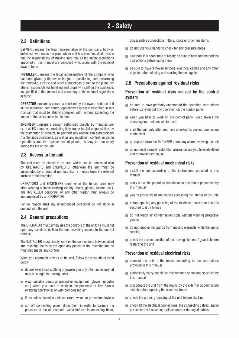
2.2 Definitions
OWNER : means the legal representative of the company, body or individual who owns the plant where unit has been installed; he/she has the responsibility of making sure that all the safety regulations specified in this manual are complied with, along with the national laws in force.
INSTALLER : means the legal representative of the company who has been given by the owner the job of positioning and performing the hydraulic, electric and other connections of unit to the plant: he/she is responsible for handling and properly installing the appliance, as specified in this manual and according to the national regulations in force.
OPERATOR : means a person authorised by the owner to do on unit all the regulation and control operations expressly described in this manual, that must be strictly complied with, without exceeding the scope of the tasks entrusted to him.
ENGINEER : means a person authorised directly by manufacturer or, in all EC countries, excluding Italy, under his full responsibility, by the distributor of product, to perform any routine and extraordinary maintenance operations, as well as any regulation, control, servicing operations and the replacement of pieces, as may be necessary during the life of the unit.
2.3 Access to the unit
The unit must be placed in an area which can be accessed also by OPERATORS and ENGINEERS; otherwise the unit must be surrounded by a fence at not less than 2 meters from the external surface of the machine.
OPERATORS and ENGINEERS must enter the fenced area only after wearing suitable clothing (safety shoes, gloves, helmet etc.). The INSTALLER personnel or any other visitor must always be accompanied by an OPERATOR.
For no reason shall any unauthorised personnel be left alone in contact with the unit.
2.4 General precautions
The OPERATOR must simply use the controls of the unit; he must not open any panel, other than the one providing access to the control module.
The INSTALLER must simply work on the connections between plant and machine; he must not open any panels of the machine and he must not enable any control.
When you approach or work on the unit, follow the precautions listed below :
n do not wear loose clothing or jewellery or any other accessory tat may be caught in moving parts
n wear suitable personal protective equipment (gloves, goggles etc.) when you have to work in the presence of free flames (welding operations) or with compressed air
n if the unit is placed in a closed room, wear ear protection devices
n cut off connecting pipes, drain them in order to balance the pressure to the atmospheric value before disconnecting them,
disassemble connections, filters, joints or other line items
n do not use your hands to check for any pressure drops
n use tools in a good state of repair; be sure to have understood the instructions before using them
n be sure to have removed all tools, electrical cables and any other objects before closing and starting the unit again
2.5 Precautions against residual risks
Prevention of residual risks caused by the control system
n be sure to have perfectly understood the operating instructions before carrying out any operation on the control panel
n when you have to work on the control panel, keep always the operating instructions within reach
n start the unit only after you have checked its perfect connection to the plant
n promptly inform the ENGINEER about any alarm involving the unit
n do not reset manual restoration alarms unless you have identified and removed their cause
Prevention of residual mechanical risks
n install the unit according to the instructions provided in this manual
n carry out all the periodical maintenance operations prescribed by this manual
n wear a protective helmet before accessing the interior of the unit
n before opening any panelling of the machine, make sure that it is secured to it by hinges
n do not touch air condensation coils without wearing protective gloves
n do not remove the guards from moving elements while the unit is running
n check the correct position of the moving elements’ guards before restarting the unit
Prevention of residual electrical risks
n connect the unit to the mains according to the instructions provided in this manual
n periodically carry out all the maintenance operations specified by this manual
n disconnect the unit from the mains by the external disconnecting switch before opening the electrical board
n check the proper grounding of the unit before start-up
n check all the electrical connections, the connecting cables, and in particular the insulation; replace worn or damaged cables

5
Engl
ish2 - Safety
n periodically check the board’s internal wiring
n do not use cables having an inadequate section or flying connections, even for limited periods of time or in an emergency
Prevention of other residual risks
n make sure that the connections to the unit conform to the instructions provided in this manual and on the unit’s panelling
n if you have to disassemble a piece, make sure that it has been properly mounted again before restarting the unit
n do not touch the delivery pipes from the compressor, the compressor and any other piping or component inside the machine before wearing protective gloves
n keep a fire extinguisher fir for electrical appliances near the machine
n on the units installed indoor, connect the safety valve of the refrigeration circuit to a piping network that can channel any overflowing refrigerant outside
n remove and leak of fluid inside and outside the unit
n collect the waste liquids and dry any oil spillage
n periodically clean the compressor compartment, to remove any fouling
n do not store flammable liquids near the unit
n do not disperse the refrigerant and the lubricating oil into the environment
n weld only empty pipes; do not approach flames or other sources of heat to refrigerant pipes
n do not bend/hit pipes containing fluids under pressure
2.6 Precautions during maintenance operations
Maintenance operations can be carried out by authorised technicians only.
Before performing any maintenance operations :
n disconnect the unit from the mains with the external disconnecting switch
n place a warning sign “do not turn on - maintenance in progress” on the external disconnecting switch
n make sure that on-off remote controls are inhibited
n wear suitable personal protective equipment (helmet, safety gloves, goggles and shoes etc.)
To carry out any measurements or checks which require the activation of the machine :
n work with the electrical board open only for the necessary time
n close the electrical board as soon as the measurement or check has been completed
n for outdoor units, do not carry out any operations in the presence of dangerous climatic conditions (rain, snow, mist etc.)
The following precautions must be always adopted :
n do not scatter the fluids of the refrigeration circuit in the surrounding environment
n when replacing an eprom or electronic cards, use always suitable devices (extractor, antistatic bracelet, etc.)
n to replace a compressor, the evaporator, the condensing coils or any other weighty element, make sure that the lifting equipment is consistent with the weight to be lifted
n in air units with independent compressor compartment, do not access the fan compartment unless you have disconnected the machine by the disconnecting switch on the board and you have placed a warning sign “do not turn on - maintenance in progress”
n contact manufacturer for any modifications to the refrigeration, hydraulic or wiring diagram of the unit, as well as to its control logics
n contact manufacturer if it is necessary to perform very difficult disassembly and assembly operations
n use only original spare parts purchased directly from manufacturer or the official retailers of the companies on the recommended spare parts list
n contact manufacturer if it is necessary to handle the unit one year after its positioning on site or if you wish to dismantle it.

6
2 - Safety
2.7 Safety labels
Identification of the refrigerant - External door
USARE SOLO
R 410AE
RECU
PERA
RE F
LUID
O - N
ON D
ISPE
RDER
E NE
LL’A
MBIE
NTE
- REG
OLAM
ENTO
CEE
N° 3
093/9
4
RECO
VER
- DO
NOT
VENT
- EE
C RE
GULA
TION
N° 3
093/9
4
SPECIAL ESTER OIL
USE ONLY
Identification of the unit Outside, on the right-hand front column
LAS BOMBAS MONTADAS EN ESTA UNIDAD NO PUEDEN TRABAJAR SIN AGUADIE PUMPEN DIESES GERÄTES DÜRFEN NICHT OHNE WASSER BETRIEBEN WERDEN
THE PUMPS ON BOARD OF THIS UNIT CAN NOT WORK WITHOUT WATERLES POMPES A BORD DE CETTE UNITE NE PEUVENT PAS FONCTIONNER SANS EAULE POMPE ABORDO DI QUESTA UNITà NON POSSONO FUNZIONARE SENZA ACQUA
Use of filter and flow switch - Adjacent to fittings
E’OBBLIGATORIO L’USO DI FILTRO E FLUSSOSTATO ACQUATHE USE OF FILTER AND FLOW SWITCH IS MANDATORY
EL USO DEL FILTRO Y DEL INTERRUPTOR DE FLUJO ES OBLIGATORIOL’UTILISATION DU FILTRE ET DU FLUXOSTAT EST OBLIGATOIREDER GEBRAUCH VON FILTER UND STRÖMUNGSWÄCHTER IST
VORGESCHRIEBEN
Lifting point - Base
ACCESSORI inclusi
ACCESSORY enclosed
ZUBEHOR eingeschlossan
ACCESSOIRE ci-inclus
ACCESSORIOS incluidos
Product code AModel BNotified body CSerial number DYear of construction ERefrigerant type F Refrigerant charge GHigh pressure HLow pressure IMain supply LStart up current MFull load current NPower input OWater operation pressure PMass QIP class R
7
Engl
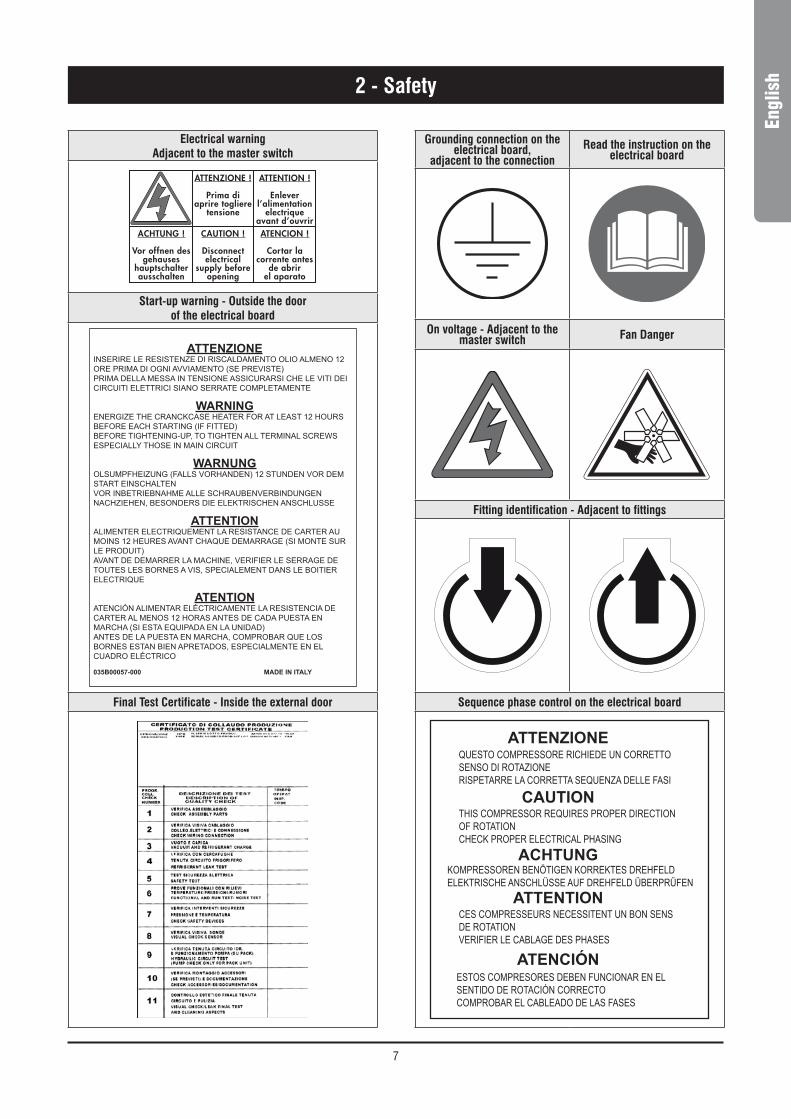
ish2 - Safety
Grounding connection on the electrical board,
adjacent to the connectionRead the instruction on the
electrical board
On voltage - Adjacent to the master switch Fan Danger
Fitting identification - Adjacent to fittings
Sequence phase control on the electrical board
ATTENZIONEQUESTO COMPRESSORE RICHIEDE UN CORRETTOSENSO DI ROTAZIONERISPETARRE LA CORRETTA SEQUENZA DELLE FASI
THIS COMPRESSOR REQUIRES PROPER DIRECTIONOF ROTATIONCHECK PROPER ELECTRICAL PHASING
KOMPRESSOREN BENÖTIGEN KORREKTES DREHFELDELEKTRISCHE ANSCHLÜSSE AUF DREHFELD ÜBERPRÜFEN
CES COMPRESSEURS NECESSITENT UN BON SENSDE ROTATIONVERIFIER LE CABLAGE DES PHASES
ESTOS COMPRESORES DEBEN FUNCIONAR EN ELSENTIDO DE ROTACIÓN CORRECTOCOMPROBAR EL CABLEADO DE LAS FASES
CAUTION
ACHTUNG
ATTENTION
ATENCIÓN
Electrical warningAdjacent to the master switch
ATTENZIONE !
Prima di aprire togliere
tensione
CAUTION !
Disconnectelectrical
supply before opening
ACHTUNG !
Vor offnen des gehauses
hauptschalter ausschalten
ATENCION !
Cortar la corrente antes
de abrirel aparato
ATTENTION !
Enlever l’alimentation
electrique avant d’ouvrir
Start-up warning - Outside the door of the electrical board
ATTENZIONEinserire le resistenze di riscaldamento olio almeno 12 ore prima di ogni avviamento (se previste)prima della messa in tensione assicurarsi che le viti dei circuiti elettrici siano serrate completamente
wArNINgenergize the cranckcase heater for at least 12 hours before each starting (if fitted)before tightening-up, to tighten all terminal screws especially those in main circuit
wArNuNgolsumpfheizung (falls vorhanden) 12 stunden vor dem start einschaltenvor inbetriebnahme alle schraubenverbindungen nachziehen, besonders die elektrischen anschlusse
ATTENTIONalimenter electriquement la resistance de carter au moins 12 heures avant chaque demarrage (si monte sur le produit)avant de demarrer la machine, verifier le serrage de toutes les bornes a vis, specialement dans le boitier electrique
ATENTIONatenciÓn alimentar eléctricamente la resistencia de carter al menos 12 horas antes de cada puesta en marcha (si esta equipada en la unidad)antes de la puesta en marcha, comprobar que los bornes estan bien apretados, especialmente en el cuadro eléctrico
035B00057-000 MADE IN ITALY
Final Test Certificate - Inside the external door

8
2 - Safety
REFRIGERANT DATA SAFETY DATA : R410A
Toxicity Low.
Contact with skin
If sprayed, the refrigerant is likely to cause frost burns. If absorbed by the skin, the danger is very limited; it may cause a slight irritation, and the liquid is degreasing. Unfreeze the affected skin with water.
Remove the contaminated clothes with great care - in the presence of frost burns, the clothes may stick to the skin. Wash with plenty of warm water the affected skin.
In the presence of symptoms such as irritation or blisters, obtain medical attention.
Contact with eyesVapours do not cause harmful effects. The spraying of refrigerant may cause frost burns.
Wash immediately with a proper solution or with tap water for at least 10 minutes, and then obtain medical attention.
IngestionVery unlikely - should something happen, it will cause frost burns.
Do not induce vomiting. Only if the patient is conscious, wash out mouth with water and give some 250 ml of water to drink. Then, obtain medical attention.
Inhalation
R410A : remarkable concentrations in the air may have an anaesthetic effect, up to fainting.
The exposure to considerable amounts may cause irregular heartbeat, up to the sudden death of the patient. Very high concentrations may result in the risk of asphyxia, due to the reduction in the oxygen percentage in the atmosphere. Remove the patient to fresh air and keep warm and at rest.
If necessary, give oxygen. In case of breathing difficulties or arrest, proceed with artificial respiration.
In case of cardiac arrest, proceed with cardiac massage. Then, obtain medical attention.
RecommendationsSemiotics or support therapy is recommended. Cardiac sensitisation has been observed that, in the presence of circulating catecholamines such as adrenalin, may cause cardiac arrhythmia and accordingly, in case of exposure to high concentrations, cardiac arrest.
Prolonged exposure
R410A : a study on the effects of exposure to 50,000 ppm during the whole life of rats has identified the development of benign testicle tumour.
This situation should therefore be negligible for personnel exposed to concentrations equal to or lower than professional levels.
Professional levels R410A : Recommended threshold : 1000 ppm v/v - 8 hours TWA.
Stability R410A : Not specified.
Conditions to avoid Do not use in the presence of flames, burning surfaces and excess humidity.
Hazardous reactionsMay react with sodium, potassium, barium and other alkaline metals.
Incompatible substances: magnesium and alloys with magnesium concentrations > 2%.
Hazardous decomposition products R410A : Halogen acids produced by thermal decomposition and hydrolysis.
2.8 Safety regulations

9
Engl
ish2 - Safety
REFRIGERANT DATA SAFETY DATA : R410A
General precautionsDo not inhale concentrated vapours. Their concentration in the atmosphere should not exceed the minimum preset values and should be maintained below the professional threshold. Being more weighty than the air, the vapour concentrates on the bottom, in narrow areas. Therefore, the exhaust system must work at low level.
Respiratory system protectionIf you are in doubt about the concentration in the atmosphere, it is recommended to wear a respirator approved by an accident-prevention
Authority, of the independent or oxygen type.
StorageCylinders must be stored in a dry and fresh place, free from any fire hazard, far from direct sunlight or other sources of heat, radiators etc.
Keep a temperature below 50 °C.
Protective clothing Wear overalls, protective gloves and goggles or a mask.
Accidental release measures
It is important to wear protective clothing and a respirator.
Stop the source of the leak, if you can do this without danger. Negligible leaks can be left evaporating under the sun, providing that the room is well ventilated.
Considerable leaks : ventilate the room. Reduce the leak with sand, earth or other absorbing substances.
Make sure that the liquid does is not channelled into gutters, sewers or pits where the vapours are likely to create a stuffy atmosphere.
Disposal The best method is recovery and recycling. If this method is not practicable, dispose according to an approved procedure, that shall ensure the absorption and neutralization of acids and toxic agents.
Fire fighting information R410A : Not flammable in the atmosphere.
Cylinders The cylinders, if exposed to fire, shall be cooled by water jets; otherwise, if heated, they may explode.
Protective fire fighting equipment In case of fire, wear an independent respirator and protective clothing.
2.8 Safety regulations (continued)

10
2 - Safety
LUBRICANT OIL DATA SAFETY DATA : POLYESTER OIL (POE)
Classification Not harmful.
Contact with skinMay cause slight irritation. Does not require first aid measures. It is recommended to follow usual personal hygiene measures, including washing the exposed skin with soap and water several times a day.
It is also recommended to wash your overalls at least once a week.
Contact with eyes Wash thoroughly with a suitable solution or tap water.
Ingestion Seek medical advice immediately.
Inhalation Seek medical advice immediately.
Conditions to avoidStrong oxidising substances, caustic or acid solutions, excess heat.
May corrode some types of paint or rubber.
Protection of therespiratory system Use in well ventilated rooms.
Protective clothing Always wear protective goggles or a mask. Wearing protective gloves is not mandatory, but is recommended in case of prolonged exposure to refrigerant oil.
Accidental release measuresIt is important to wear protective clothing and, especially, goggles.
Stop the source of the leak. Reduce the leak with absorbing substances (sand, sawdust or any other absorbing material available on the market).
Disposal The refrigerant oil and its waste will be disposed of in an approved incinerator, in conformity with the provisions and the local regulations applicable to oil waste.
Fire fighting information In the presence of hot liquid or flames, use dry powder, carbon dioxide or foam. If the leak is not burning, use a water jet to remove any vapours and to protect the personnel responsible for stopping the leak.
Cylinders The cylinders exposed to a fire will be cooled with water jets in case of fire.
Fire fighting protective equipment In case of fire, wear an independent respirator.
2.8 Safety regulations (continued)

11
Engl
ish3 - Transport, Handling and Storage
AQL/AQH units are supplied fully assembled and tested (except for accessories supplied loose in the units – absorbers, filter, etc.). They are ready to be installed and started on the field.
R410A units are only charged with liquid refrigerant and with oil in the quantity required for operation.
WARNING
The low pressure side of the refrigerating circuit on R410A units shall be charged by means of the service valve arranged on the thermal expansion valve before the device is operated.
3.1 Inspection
The unit shall be immediately inspected upon receipt to find out any damage since it has been delivered ex works and transported at the customer’s risk. It is also necessary to make sure that all the parcels specified on the delivery note have been delivered.
Any damage you may find out shall be immediately reported in writing to the carrier. Even if the damage is only on the surface, please notify our local representative too.
The manufacturer disclaims all responsibility for the shipment even if it has provided for its organisation.
3.2 Handling
AQL/AQH units are designed to be lifted from above, by means of cables and eyebolts. A spacer shall be arranged between the cables in order to prevent them from damaging the unit (see the figure aside).
Before handling the devices, make sure the site you have chosen for the installation can withstand its weight and support its mechanical impact.
Avoid touching sharp parts (such as the fins of batteries, for example) while handling the unit.
WARNING
The unit shall never be placed on rollers.
Act as follows to lift and handle the unit :
n Insert and secure the eyebolts into the frame holes which have been marked on purpose.
n Connect the cables to the eyebolts.
n Insert the spacer between the cables.
n Provide for hooking at the centre of gravity of the device.
n Cables shall have such a length that the angle they form with the horizon when under tension is not less than 45°.
Space requirements request to handling
Protect cabinet during lifting
Holes Ø 30 mm
WARNING
While lifting and handling the unit, pay attention. Otherwise, you might damage the finned block of the coils arranged on both sides of the unit. The sides of the unit shall be protected by cardboard or plywood sheets.

12
3 - Transport, Handling and Storage
WARNING
Until the unit is ready for operation, do not remove the plastic envelope and the coi l protections which are intended to prevent dirt, dust and any foreign matter from penetrating into the unit through the inlets of fans or from damaging the external surfaces.
3.3 Anchoring
It is not essential to secure the unit to the foundations, unless in areas where there is a serious risk of earth-quake, or if the appliance is installed on the top of a steel frame.
3.4 Storage
If the unit is to be stored before the installation for some time, take at least the following precautions to prevent damage, corrosion and/or deterioration :
n Make sure all openings, such as for example water connections, are well plugged and sealed.
n Never store the units in a room where temperature is above 50 °C (R410A units) or where the units are directly exposed to the sunlight.
n Minimum storage temperature is -25 °C.
n It is recommended to leave the finned coils covered to protect them against any risk of corrosion, especially if building works are still in progress.
n Store the units in areas where minimum activity is likely to take place in order to avoid any risk of accidental damage.
n Never use steam to clean the unit.
n Remove all the keys required to have access to the control panel and give them to the person in charge of the field.
It is also recommended to provide for visual inspections at regular intervals.
13
Engl
ish4 - Installation
4.1 Installation Site
DANGER
Before installing the unit, make sure that the building structure and/or the supporting surface can withstand the weight of the device. The weights of the units are detailed by Chapter 9 of this manual.
These units have been designed to be installed on the floor, in the open air. As a standard, they are equipped with rubber vibration-damping supports which shall be arranged in the middle, beneath the supporting plates.
When the unit is to be installed on the ground, provide for a concrete bedplate which shall assure a uniform distribution of the weights. No special subbase is generally required.
When selecting the installation site, never forget to consider as follows :
n The longitudinal axis of the unit shall be parallel to the direction of the prevailing winds so as to assure a uniform air distribution on finned exchangers.
n The unit shall never be installed in the proximity of chimneys for the discharge of boiler flue gases.
n The unit shall never be installed downwind of sources of grease contaminated air, such as for example the outlets of large-kitchen extractors. Otherwise, grease might build up on the fins of refrigerant / air exchangers or condensers, act as a fixing agent for any sort of atmospheric impurity and rapidly cause the exchangers to clog.
n The unit shall never be installed in areas exposed to heavy snowfalls.
n The unit shall never be installed in areas exposed to flooding or beneath drip stones, etc.
n The unit shall never be installed in narrow inner court yards or in any other restricted space where the noise may be reflected by the walls or where the air expelled by the fans may short-circuit on the refrigerant/air heat exchangers or condensers.
n The installation site shall be characterised by the presence of the space required for air circulation and for the performance of maintenance operations (see chapter 9 for further details).
4.2 External Water Circuit
WARNING
The external water circuit shall guarantee a constant water flow rate through the circulating refrigerant/water heat exchanger (evaporator) under steady operating conditions and in case of a load variation.
The circuit shall be composed by the following elements :
n A circulation pump which can ensure the necessary flow rate and head.
n The total content of the primary water circuit shall never be lower than 2.5 lt/kW in terms of refrigerating capacity. If the total water volume in the primary circuit should be unable to reach such a value, an additional heat-insulated storage tank should be installed. This tank is intended to avoid any repetitive start of the compressor.
n A membrane expansion tank complete with a safety valve and a drain which shall be visible.
NOTE
The expansion tank shall be dimensioned in such a way that it can absorb a 2% expansion of the total volume of the water in the plant (exchanger, pipelines, uses and storage tank, if available). The expansion tank shall never be insulated when the circulating fluid is not flowing through it.
A differential pressure switch is mounted as a standard. It will stop the unit whenever it senses a load loss through the heat exchanger which may result in a flow rate problem.
In addition :
n Install on/off valves (accessory) on the lines at the inlet and outlet of the manifolds of the exchangers (evaporator).
n Arrange a by-pass complete with an on/off valve between the manifolds of the heat exchangers.
n Arrange air vent valves at the high points of the water lines.
n Arrange drain points complete with plugs, clocks, etc. in the proximity of the low points of the water lines.
n Insulate the water lines to prevent the heat from blowing back into the unit.

14
External water circuit AQL/AQH 20 to 35 - R410A
External water circuit AQL/AQH 40 to 75 - R410A - Basic Unit
4 - Installation
1
B
A
10
5
G
G
9
11
1112
12
13
INLET
OUTLET
FS I
8
E D
8
components1 Plate heat exchanger5 Water filter8 Pressure point/drain valve9 Water outlet
10 Water inlet11 Globe valve12 Flexible pipes13 By-pass valve
safety/control devicesa Inlet water temperature sensorB Outlet water temperature sensord Vent valve (105 mbar)e Water safety valve (3 bar)fs Flow switchG Thermometeri Hydrometer
Unit side
safety/control devicesa Inlet water temperature sensorB Outlet water temperature sensorc Water differential pressure switch (105 mbar)d Vent valvee Water safety valve (3 bar)f Manometerfs Flow switchG Thermometeri Hydrometer
Unit sidey Water drain
10 10
9 9
13
12
12 11
11
4
5
3
8
6
3
Y
HYDROKIT
INLET
OUTLET
Y
Y
2
3
1
7
FS
F
E
ED
D
CA
B
I
G
G
components1 Plate heat exchanger2 Pump3 Draining valve4 Water buffer tank5 Water filter6 Automatic water charging valve7 Pressure expansion tank8 Water charging line9 Water outlet
10 Water inlet11 Globe valve12 Flexible pipes13 By-pass valve
15
Engl
ish
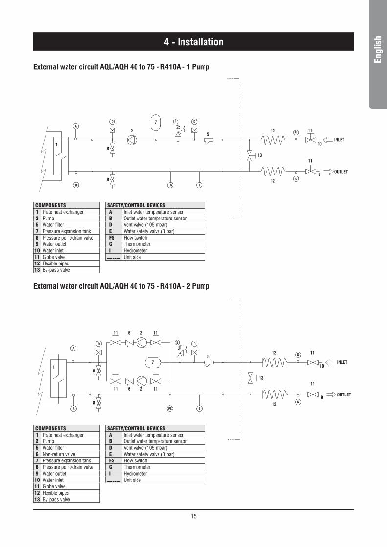
External water circuit AQL/AQH 40 to 75 - R410A - 1 Pump
External water circuit AQL/AQH 40 to 75 - R410A - 2 Pump
4 - Installation
8
D
2
E
8
IFS
OUTLET
INLET
13
12
12 11
11
9
G
G
5
10
A
B
1
7D
components1 Plate heat exchanger2 Pump5 Water filter7 Pressure expansion tank8 Pressure point/drain valve9 Water outlet
10 Water inlet11 Globe valve12 Flexible pipes13 By-pass valve
safety/control devicesa Inlet water temperature sensorB Outlet water temperature sensord Vent valve (105 mbar)e Water safety valve (3 bar)fs Flow switchG Thermometeri Hydrometer
Unit side
D
71
B
A
10
5
G
G
9
11
1112
12
13
INLET
OUTLET
FS I
8
E D
8
2
2
6
6
11 11
1111
components1 Plate heat exchanger2 Pump5 Water filter6 Non-return valve7 Pressure expansion tank8 Pressure point/drain valve9 Water outlet
10 Water inlet11 Globe valve12 Flexible pipes13 By-pass valve
safety/control devicesa Inlet water temperature sensorB Outlet water temperature sensord Vent valve (105 mbar)e Water safety valve (3 bar)fs Flow switchG Thermometeri Hydrometer
Unit side

16
External water circuit AQL/AQH 40 to 75 - R410A - 1 Pump + tank
External water circuit AQL/AQH 40 to 75 - R410A - 2 Pump + tank
4 - Installation
2
8
DE
8
IFS
OUTLET
INLET
13
12
12 11
11
9
G
G
5
10
A
B
1
7
D
3
Y
4
1111
components1 Plate heat exchanger2 Pump3 Draining valve4 Water buffer tank5 Water filter7 Pressure expansion tank8 Pressure point/drain valve9 Water outlet
10 Water inlet11 Globe valve12 Flexible pipes13 By-pass valve
safety/control devicesa Inlet water temperature sensorB Outlet water temperature sensord Vent valve (105 mbar)e Water safety valve (3 bar)fs Flow switchG Thermometeri Hydrometer
Unit sidey Water drain
4
Y
3
D
7
1
B
A
10
5
G
G
9
11
1112
12
13
INLET
OUTLET
FS I
8
E D
8
2
211 11
1111
6
6
components1 Plate heat exchanger2 Pump3 Draining valve4 Water buffer tank5 Water filter6 Non-return valve7 Pressure expansion tank8 Pressure point/drain valve9 Water outlet
10 Water inlet11 Globe valve12 Flexible pipes13 By-pass valve
safety/control devicesa Inlet water temperature sensorB Outlet water temperature sensord Vent valve (105 mbar)e Water safety valve (3 bar)fs Flow switchG Thermometeri Hydrometer
Unit sidey Water drain
17
Engl
ish4 - Installation
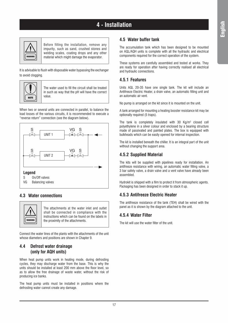
WARNING
Before filling the installation, remove any impurity, such as sand, crushed stones and welding scales, coating drops and any other material which might damage the evaporator.
It is advisable to flush with disposable water bypassing the exchanger to avoid clogging.
NOTE
The water used to fill the circuit shall be treated in such as way that the pH will have the correct value.
When two or several units are connected in parallel, to balance the load losses of the various circuits, it is recommended to execute a “reverse return” connection (see the diagram below).
UNIT 1
UNIT 2
LegendS On/Off valvesVG Balancing valves
4.3 Water connections
WARNING
The attachments at the water inlet and outlet shall be connected in compliance with the instructions which can be found on the labels in the proximity of the attachments.
Connect the water lines of the plants with the attachments of the unit whose diameters and positions are shown in Chapter 9.
4.4 Defrost water drainage (only for AQH units)
When heat pump units work in heating mode, during defrosting cycles, they may discharge water from the base. This is why the units should be installed at least 200 mm above the floor level, so as to allow the free drainage of waste water, without the risk of producing ice banks.
The heat pump units must be installed in positions where the defrosting water cannot create any damage.
4.5 Water buffer tank
The accumulation tank which has been designed to be mounted on AQL/AQH units is complete with all the hydraulic and electrical components required for the correct operation of the system.
These systems are carefully assembled and tested at works. They are ready for operation after having correctly realised all electrical and hydraulic connections.
4.5.1 Features
Units AQL 20-35 have one single tank. The kit will include an Antifreeze Electric Heater, a drain valve, an automatic filling unit and an automatic air vent.
No pump is arranged on the kit since it is mounted on the unit.
A tank arranged for mounting a heating booster resistance kit may be optionally required (5 traps).
The tank is completely insulated with 30 Kg/m3 closed cell polyethylene in a silver colour and enclosed by a bearing structure made of passivated and painted plates. The box is equipped with bulkheads which can be easily opened for internal inspection.
The kit is installed beneath the chiller. It is an integral part of the unit without changing the support area.
4.5.2 Supplied Material
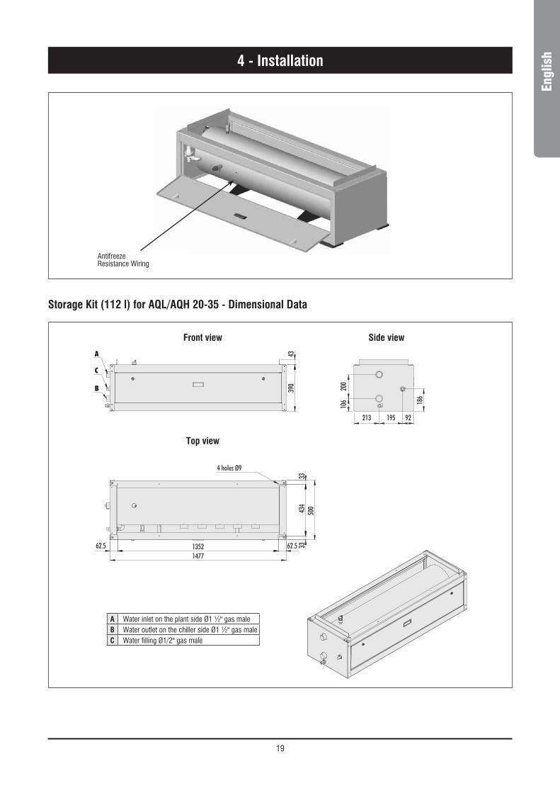
The kits will be supplied with pipelines ready for installation. An antifreeze resistance with wiring, an automatic water filling valve, a 3 bar safety valve, a drain valve and a vent valve have already been assembled.
Hydrokit is shipped with a film to protect it from atmospheric agents. Packaging has been designed in order to stack it up.
4.5.3 Antifreeze Electric Heater
The antifreeze resistance of the tank (TEH) shall be wired with the panel as it is shown by the diagram attached to the unit.
4.5.4 Water Filter
The kit will use the water filter of the unit.

18
4.6 Power supply
DANGER
Before carrying out any operations on the electrical system, make sure that the unit is deenergized.
DANGER
It is important that the appliance is grounded.
WARNING
The company in charge of the installation shall conform to the standards applicable to outdoor electrical connections.
The manufacturer may not be held liable for any damage and/or injury caused by failure to comply with these precautions.
The unit conforms to EN 60204-1.
The following connections shall be provided :
n A 3-phase and grounding connection for the power supply circuit.
n The electrical distribution system shall meet the power absorbed by the appliance.
n The disconnecting and magnetothermal switches must be sized to control the starting current of the unit.
n The power supply lines and the insulation devices must be designed in such a way that every line independent.
n It is recommended to install differential switches, to prevent any damage caused by phase drops.
n The fans and compressors are supplied through contactors controlled from the control panel.
n Each motor is provided with an internal safety thermal device and external fuses.
n The power supply cables must be inserted into dedicated openings on the front of the unit, and the will enter the electrical board through holes drilled on the bottom of the board.
4 - Installation
CAUTIONS
The unit + tank system shall be equipped with a filter. Use the filter + union as it is shown by Figure 1.
Positioning rubbershock absorbers
Water filter position
Figure 1
4.5.5 Installation Procedure
For the size 20-35 the hydrokit shall be arranged beneath the unit. It will not change its overall dimensions (Figure 1).
Arrange the rubber shock absorbers beneath the kit before providing for its connection.
Provide for the hydraulic and electrical connections. Doing that, observe the diameters shown by the quoted drawings.
The wiring for the standard antifreeze resistance is arranged as it is shown by . The resistance is connected with the main terminal box.
See the wiring diagram attached to the unit for the correct execution of the electrical connections.
Install the water filter as it is shown by Figure 1.
Instead for the size 40-75 the Hydrokit if required, will be installed on the unit.
19
Engl
ish
AntifreezeResistance Wiring
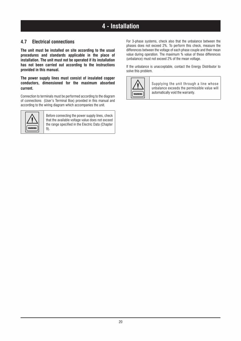
Storage Kit (112 l) for AQL/AQH 20-35 - Dimensional Data
4 - Installation
1352
4 holes Ø9
1477
92 213 195
62.5 62.5 33
33
434
390
186
200
106
43
500
A
C
B
Front view Side view
Top view
A Water inlet on the plant side Ø1 ½" gas maleB Water outlet on the chiller side Ø1 ½" gas maleC Water filling Ø1/2" gas male
20
4 - Installation
4.7 Electrical connections
The unit must be installed on site according to the usual procedures and standards applicable in the place of installation. The unit must not be operated if its installation has not been carried out according to the instructions provided in this manual.
The power supply lines must consist of insulated copper conductors, dimensioned for the maximum absorbed current.
Connection to terminals must be performed according to the diagram of connections (User’s Terminal Box) provided in this manual and according to the wiring diagram which accompanies the unit.
WARNING
Before connecting the power supply lines, check that the available voltage value does not exceed the range specified in the Electric Data (Chapter 9).
For 3-phase systems, check also that the unbalance between the phases does not exceed 2%. To perform this check, measure the differences between the voltage of each phase couple and their mean value during operation. The maximum % value of these differences (unbalance) must not exceed 2% of the mean voltage.
If the unbalance is unacceptable, contact the Energy Distributor to solve this problem.
WARNING
Supplying the uni t through a l ine whose unbalance exceeds the permissible value will automatically void the warranty.

21
Engl
ish
AQL/AQH Version - Electrical Connections
L1
L2
L3
L4
L1
L2
L3
PE
POWER LINE400/3+N/50+PE
TERMINAL BOARD ON THE MACHINE USER CONNECTIONS
MAIN SWITCH
N
PE
1
2
3
4
TB5
ACB
TB5
ON/OFF 01
COMMON 02
HOT/COLD 03 HEATING/COOLING SELECTION
02
07
02
09
EXTERNAL INTERLOCK
ALARMED UNITMAX 0,5A @ 250Vac
ON/OFF REMOTE SWITCH
NIGHT OR DOUBLE SET POINTMODE SELECTION
LOAD SHEDDING MODE SELECTION
EXTERNAL WATER FLOW SAFETY SWITCH
TERMINALS ON THE MACHINE
TERMINALS CONTROL BOARD
TERMINALS ON THE EXTERNAL CONNECTIONS
VOLTAGE-FREE CONTACTS
NOTE: always refers to the diagram on the machine
}}}}
}}
}}
4 - Installation

22
4 - Installation
AQC Version - Electrical Connections
23
Engl
ish5 - Start-up
WARNING
The unit must be started for the first time by personnel suitably trained by one of Authorised Service Centre. Failure to meet this requirement will immediately void the warranty.
NOTE
The operations carried out by authorised personnel are limited to the start-up of the unit, and do not include any other operation on the plant, such as, for example, electrical and hydraulic connections etc. All the other operations before start-up, including oil pre-heating for at least 12 hours, must be performed by the Installer.
5.1 Preliminary check
The checks listed below shall be performed before starting the unit and before the arrival of the personnel authorised.
n Check the section of power supply and grounding cables; make sure that terminals are tightened and check the correct operation of contactors, with the main switch open.
n Check that any voltage and phase variation in the power supply does not exceed the prefixed thresholds.
n Connect the contacts of the flow switch and the thermal relay of the pump and of the other devices (if any), to terminals 1-2 and 3-4, respectively.
n Check that the components of the external water circuit (pump, user equipment, filters, power supply tank and reservoir, if any) have been installed properly, and according to the manufacturer’s instructions.
n Check the filling of the hydraulic circuits, and make sure that the fluid circulation is correct, without any trace of leaks and air bubbles. If you use ethylene glycol as antifreeze, check that its percentage is correct (do not exceed 35% glycol percentage).
n Check that the direction of rotation of the pumps is correct, and that fluids have been circulating for at least 12 hours for both pumps. Then, clean the filters on the suction side of the pumps.
n Adjust the liquid distribution network in such a way that the flow rate is within the specified range.
n Check that the water quality is up to the specifications.
n Check that oil heaters, if any, have been turned on at least 12 hours
before.
5.2 Start-up
Start-up sequence :
n Turn on the Main switch (at least 12 hours before).
n Check that the oil in the compressor has reached the requested temperature (the minimum temperature outside the pan must be approx. 40°C) and that the auxiliary control circuit is energised.
n Check the operation of all the external equipment, and make sure that the control devices of the plant are properly calibrated.
n Start the pump and check that the water flow is correct.
n Set the desired fluid temperature on the control board.
n Start the appliance (see Chapter 6).
n Check the correct direction of rotation of compressors. Scroll compressors cannot compress the refrigerant when they rotate in the opposite direction. To make sure that they are rotating in the correct direction, simply check that, just after the start-up of the compressor, the pressure drops on the LP side and rises on the HP side. Furthermore, if a scroll compressor rotate in the opposite direction, there is a considerable rise in the sound level of the unit, as well as in a dramatic reduction of current absorption compared to normal values. In case of wrong rotation, the scroll compressor can be definitely damaged. Phase monitor is assembled in the unit as a standard to prevent wrong compressors rotation.
n After about 15 minutes of operation check that there are no bubbles, through the sight glass on the liquid line.
WARNING
The presence of bubbles may indicate that a part of the refrigerant charge has been released in one or more points. It is important to remove these leaks before proceeding.
n Repeat the start-up procedure after removing the leaks.
5.3 Checking the operation
Check the following :
n The temperature of the water entering the evaporator.
n The temperature of the water leaving the evaporator.
n The level of the water flow rate in the evaporator, if possible.
n The current absorption upon the start of the compressor and in case of stabilised operation.
n The fan’s current absorption.
Check that the condensing and evaporation temperatures, during operation at high and low pressure detected by the pressure gauges of the refrigerant, are within the following range :
(On the units not provided with HP/LP pressure gauges for the refrigerant, connect a pressure gauge to the Shrader valves on the refrigeration circuit).
HP side Approx. 15 to 21 °C above the temperature of the air entering the condenser, for R410A units.
LP side Approx. 2 to 4 °C below the temperature of the leaving chilled water, for R410A units.
5.4 Delivery to the customer
n Train the user according to the instructions provided in Section 6.

24
6.1 Electronic Card Control
Keyboard
Display Meaning Min value Max value Step Default value 410A
1. OPEr Cooling/Heating mode selection COOL HEAt --- COOL
2. CSP Cooling Setpoint CSPL 23 0.5 12
3. HSP Heating setpoint 20 47 1 40
4. wtc Control Mode Operation ewt lwt --- Ewt
5. nB Neutral Band valid in LWT control 1 6 0.5 2
OPEr : parameter used to select operative mode between Cool and Heat. Active only if unit is heatpump.Other parameters to be used only by authorized technician.
SM1 Switch
6 - AQL/AQH Control
SM1 switch :
– Position 0 : machine OFF. The electrical heaters and pump may be enabled.
– Position 1 : machine ON.
button :makes it possible to horizontally scroll through the MENUS and to display the parameter values.
button :makes it possible to vertically scroll through the MENUS and SUB-MENUS and to increase the numerical value of the parameters.
Test switch (internal)Star ts an automatic testing procedure for all the main functions of the unit.
Two levels of menu are used, standard and factory. The factory level requires a 3 digit code for access.
At any time the standard parameter level menu can be entered by pressing simultaneously the test button and both display buttons for 5s.
In either parameter level menu if no button is pressed for 10s the display reverts back to normal mode.
The parameters are scrolled using the button and selected using the button.
When selected the values can be changed by using the button to scroll from the present value to max then min and can be selected by pushing the button. After selection the menu will return to the beginning of the same parameter level menu.

25
Engl
ish
DIP OFF ON STANDARD
1 Pump ON only if the unit is ON Pump always ON OFF
2 Step ventilation Continuous ventilation OFF
3 Pump Off in antifreeze protection Pump On in antifreeze protection ON
4 Discharge of comp. 1 Discharge of comp. 2 OFF
5 Normal Slave OFF
6 Ambient temperature compensation No compensation ON
7 Enable input 5 pump’ thermal switch Disable input 5pack unit = OFFnon pack = ON
8 Forced defrosting OFF Forced defrosting ON OFF
9 Serial address OFF
10 Serial address OFF
11 Serial address OFF
12 Serial address OFF
6.2 Dip Switches
The control is provided with 2 DIP switch blocks: DSW1 (12 dips) and DSW2 (8 dips).
Function of DSW1 DIPS (user setting)
DSW2 dips setting : only for service technician
Display keys
Display screen
6 - AQL/AQH Control
Display keys
All the information is displayed on 4 displays (7-segments).
Cool and heat setpoint : can be selected inside the standard parameter menu.
Use the and keys to enter the display menus as follows :

26
1 2 3
PArA (Parameters)
UnIt 2E or 2D
DE
Select to show present value
Vs
CSPT
HSPT
EPIC
tD
SEnS (Sensor)
EWT
Select to show present value(if connected)
LWT
CP
EP
CPS – saturated temperature
EPS – saturated temperature
Dis
OAT – OC1T – OC2T
ALAr (Existing Faults) See alarm list below Scrolls through all active faults (if any)
HRS (Running hours)
C1 (x10 hrs)
Select to show hrs C2 (x10 hrs)
tC1 (hrs)
tC2 (hrs)
Log (Alarm log) Same choice as alarm list Scrolls through last 10 alarms in order
StAt
C1 ON or OFF
C2 ON or OFF
rv ON or OFF
TH ON or OFF
THC ON or OFF
Pump ON or OFF
OFAN1 HI or LO or OFF
OFAN2 HI or LO or OFF
dEIC De-ice in operation
BYP ON or OFF
Mode OFF or COOL or HEAt
6 - AQL/AQH Control

27
Engl
ish6 - AQL/AQH Control
Stat - status
MOdE Off, Cool
ON or OFF
ON or OFF
ON or OFF
ON or OFF
etc - up to 10 alarms
Alarm code (see list)
value
value
value x 10
value x 10
Alarm code (see list)
value
value
value
value
value
value
value
value
value
value
value
value
value
value
value
2E or 2D
OFF or HI or LO
OFF or HI or LO
OF2 - Outdoor fan 2
OF1 - Outdoor fan 1
PUMP
tH - Electrical heater
C2 - compressor
C1 - compressor
tC2 since last test mode
tC1 since last test mode
C2 compressor 2
C1 compressor 1
OCt - Coil 2 temperature
OCt - Coil temperature
OAt - Outdoor air temperature
dIS - Discharge temperature
EPS - Saturated temperature
CPS - Saturated temperature
EP - Evaporating pressure
CP - Condensing pressure
Lut - Leaving water temperature
Eut - Entering water temperature
dt - not used
HSPt - Heating set point
CSPt - Cooling set point
us - Variable speed
dE - not used
Unit - unit type
Log - last 10 alarms
HRS - running hours
ALAr - existing alarms
SEnS - Sensors
PArA - Parameters

28
6.3 ALAr and LOg MenusThe activated alarms of the unit are displayed in the ALAr menu. More alarms can be activated at the same time. The alarms are recorded in a permanent LOG memory.
The last 10 recorded alarms are displayed in the LOg menu. The fol-lowing table shows the alarm codes and description:
Code Alarm description Auto Manual Notes
ADC microprocessor error l
CPF failure of HP transducer, off scale l
EPF failure of LP transducer, off scale l
REF refrigerant leak - low pressure l
CPnc failure of HP transducer, unchanged pressure l
EPnc failure of LP transducer, unchanged pressure l
CFC1 failure of compressor 1 l wrong rotation
CFC2 failure of compressor 2 l wrong rotation
EWTH failure of return water probe l short-circuit
EWTL failure of return water probe l not connected
LWTC no variation in the leaving water temperature l
LWTH failure of leaving water probe l short-circuit
LWTL failure of leaving water probe l not connected
DISH failure of compressor discharge temperature probe l short-circuit
DISL failure of compressor discharge temperature probe l not connected
OATH failure of air temperature probe l short-circuit
OATL failure of air temperature probe l not connected
OC1H failure of temperature probe - coil 1 l short-circuit
OC1L failure of temperature probe - coil 1 l not connected
OC2H failure of temperature probe - coil 2 l short-circuit
OC2L failure of temperature probe - coil 2 l not connected
HPP first high pressure protection l stop1 compressor
HP high pressure protection from transducer l l auto reset 3 times
HPC high pressure protection - locked circuit l
LP low pressure protection l l auto reset 3 times
DIS excessive discharge temperature of compressors l
LO too low leaving water temperature l l auto reset 3 times
HI excessive entering water temperature l
FS electrical flow switch or water differential pressure switch l
CF1 thermal protection, compressor 1 l
CF2 thermal protection, compressor 2 l
OF1 thermal protection, fans l
PF thermal protection, pump l
LOu low water volume l
EEP microprocessor error l
JUMP failure dip switch l not connected
ConF wrong configuration l
6 - AQL/AQH Control

29
Engl
ish
6.4 SEnS Menu – Sensors reading
Displayed Code MeaningEWT entering water temp
LWT leaving water temp
CP discharge pressure
EP intake pressure
CPS sat. temperature (discharge)
EPS sat. temperature (intake)
Dis compressor’s discharge temp
OAT room air temp
OCT 1 probe temperature in coil 1
OCT 2 probe temperature in coil 2
High StaticPressure Fan P(Pa) Fan RPM Parameter
40
145 900 69
195 1000 79
220 1050 84
245 1100 100
45
145 900 69
195 1000 79
220 1050 84
245 1100 100
50
145 900 69
195 1000 79
220 1050 84
245 1100 100
6045 1000 79
68 1050 84
120 1100 100
6545 1000 79
68 1050 84
120 1100 100
7545 1000 79
68 1050 84
120 1100 100
6.5 SIF version configurationUnits equipped with special inverter fans (SIF) can be set-up on the field to give the unit a specific static pressure.
By entering parameter CO5 (FCM control), it is possible to modify high static pressure.
The table below shows the correspondence between chiller model, fan RPM, high static pressure.
6 - AQL/AQH Control

30
7 - AQC Control
Introduction
This document contains the information and the operating instructions for AQC 2 compressors & electronic control.
This information is for the after-sales service and the production operators, for the end-of-line testing.
Main characteristics
– microprocessor control
– user-friendly keyboard
– access code to enter the Manufacturer’s Level
– access code to enter the Assistance Level
– alarm and LED
– backlighted LCD
– pump-down logic (start-stop)
– rotation of the compressor operation
– oil return function
– night mode (or Low Noise) control
– counting of the pump/compressors’ hours of operation
– display of discharge and suction pressure values
– display of temperature sensor
– history of stored alarms (option)
– programming of different setpoints with 4 ranges of time/setpoint.
The following accessories can be also connected :
– serial communication RS485 card; to connect the “Chiller Control” to a BMS network
– remote display terminal
– wire remote control.
7.1 Control of AQC with 2 compressors - The “CHILLER CONTROL” system
AQC units are provided with a microprocessor card which is fully programmed by default for the control of a condensing unit.
The control system consists of :
Keyboard & Display Terminal
General information
The figure shows the terminal with the front door open.
It is provided with a LCD 4 lines x 20 columns, keyboard and microprocessor-controlled LED’s, so as to allow the programming of the control parameters (setpoint, differential bands, alarm thresholds) and themain operations to be carried out by the user.
Terminal & Key Board description
The terminal makes it possible to carry out the following operations:
– the initial configuration of the machine
– the change of all the main operating parameters
– the display of the detected alarms
– the display of all the measured quantities
The terminal and the card are connected by a 6-way phone cable.
The connection of the terminal to the basic card is not essential for the normal operation of the controller.

31
Engl
ish7 - AQC Control
7.2 Display
The display is an LCD 4 lines x 20 columns. The quantities and the information about the operation of the unit are alternated in the form of subsequent screens, named.
7.3 Keyboard
Arrows key - Up/Down/Enter
If the cursor is in the top left-hand corner (Home), press the UP/DOWN keys to access the subsequent masks associated to the selected branch. If a mask includes some value setting fields and you press the ENTER key, the cursor will reach these fields.
Once you have reached the quantity setting field, you can modify any value (within the expected limits) by pressing the UP/DOWN keys.
After you have selected the desired value, press the ENTER key again to store it.
Access to the "display mask" of the machine status.
Esc key : allows you to move from one mask to another.
Alarm key : used to display the alarms, to reset them in manual. Press it one to display the mask of the activated alarm, press it again to reset the alarm signal.
+
Prg+Esc keys : pressing these keys at the same time, allows you to turn the unit On/Off.
Up-down keys : allows you to set the control parameters' values and to move from one mask to another (not backlighted).
Enter key : used to move the cursor inside the masks and to save the values of the set parameters.
+
Alarm+Enter keys : press these keys at the same time to enter the "storical alarm" after 1' come back at status machine menu.
User ManufacturedMaintenanceIn/Out
SetpointReleaseOn/OffDaily time zone

32
7 - AQC Control
Code Alarm unit description CompressorStatus
FanStatus
PumpStatus
Aut/Man Reset Delay Notes
AL02 Flow meter/Interbloc alarm Off Off Off Man Parameters
AL03 High pressure “manual reset” Off On On Man No
AL05 Failure of transducer B6-SP On Max On Auto 10 sec TXV only
AL07 Failure of transducer B7-DP On Max On Auto 10 sec
AL09 Failure of sensor B3-Tair On Max On Auto 10 sec
AL15 Failure of sensor B8-T tandem On Max On Auto 10 sec
AL17 Maintenance of compressor 1 On On On Man No
AL18 Maintenance of compressor 2 On On On Man No
AL22 Failure of clock card On On On Man No
AL23 Thermal switch, compressor 1 Off Comp. 1 On On Man No
AL23a Thermal switch, compressor 1-AUTO Reset Off Comp. 1 On On Auto
AL24 Thermal switch, compressor 2 Off Comp. 2 On On Man No
AL24a Thermal switch, compressor 2-AUTO Reset Off Comp. 2 On On Auto
AL27 Low pressure alarm Off On On Man Parameters
AL27a Low pressure alarm -AUTO Reset Off On On Auto
AL29 Thermal switch, fans Off Off On Man No
AL29a Thermal switch, fans- AUTO Reset Off Off On Auto
AL33 Eprom failure Off Off Off Man No
AL60 High limit discharge temperature Off Off Off Man No
AL60a High limit discharge temperature Off Off Off Auto
7.4 Alarms
SetpointPressing the Set key allows you to enter the Set point level accessible to the user.
The parameters that can be set are listed below, along with the limit values and the default values (standard shop settings) :
User parameters Control mode Min. value Max. value Default
System On/Off
System 1 # —— OFF ON OFF

33
Engl
ish8 - Product Description
8.1 General Information
AQL/AQH units are one-block type with one refrigerant circuit. They are intended to cool down the water required for any air-conditioning application as well as any other fluid, such as for example glycol water.
These units are completely assembled at works. They are equipped with all the refrigerating connections and the internal electrical wiring required for a rapid installation on the field.
An operation test is performed after assembly, with water flowing through the refrigerant/water exchanger in order to make sure that every refrigerating circuit is properly working. The refrigerating circuits of every unit are pressure tested before inspection, drained and charged with R410A.
A low noise level is the result of a careful study. It is achieved on chillers by using technologically advanced components without negatively affecting the operation performances and limits of the units.
AQL models can cool down chilled water at a temperature between + 18 and - 8 °C.
AQH heat pump models can warm up water at a temperature between 20 °C and 50 °C for AQH 20-35 and 55 °C for AQH 40-75.
All units can operate with a double set point.
Body and Frame
The base and frame of these units are made with galvanized steel elements, assembled with stainless steel screws. All panels can be removed to ensure easy access to internal components. All galvanized steel parts are protected by epoxy powder paint.
Compressors
The models are equipped with two SCROLL airtight tandem compressors with an internal motor protection.
The compressors of all models are assembled on rubber shock absorbers. Their motors can be directly started. They are cooled down by the aspirated refrigerant gas and equipped with internal thermistor protections against overloads.
Overload protections are automatically reset after having tripped. The compressor terminal box has an IP21 protection degree.
Compressors are powered on and off by the microprocessor of the unit control system which is intended to control the delivery of the thermal refrigerating capacity.
Evaporators
Evaporators are made of stainless steel plates. They are thermally insulated by means of a thick flexible insulating mattress with closed cells. The maximum operating pressures correspond to 10 bar for the water side and to 45 bar for the refrigerant side. Antifreeze protection for the water in the exchangers is ensured by electrical heaters and differential pressure switches. The water side of these exchangers is connected by manifolds which will provide for the connection to the plant by means of one single 1”1/2 (for the size 20-35) and 2” (for the size 40-75)gas threaded attachment.
Condensing coils
Condensers are coils made of copper tubes arranged in staggered rows and mechanically expanded inside an aluminium finned pack.
The maximum operating pressure on the refrigerant side of the condensing batteries is 45 bar.
Condenser Fans
The condenser fans are of a helical type. They are directly coupled and have an impeller with wing contoured aluminium blades. Each fan is equipped with a galvanised steel accident-prevention protection which is painted after manufacture. The fans motors are completely closed. They have an IP54 protection degree and a protection thermostat embedded in the windings.
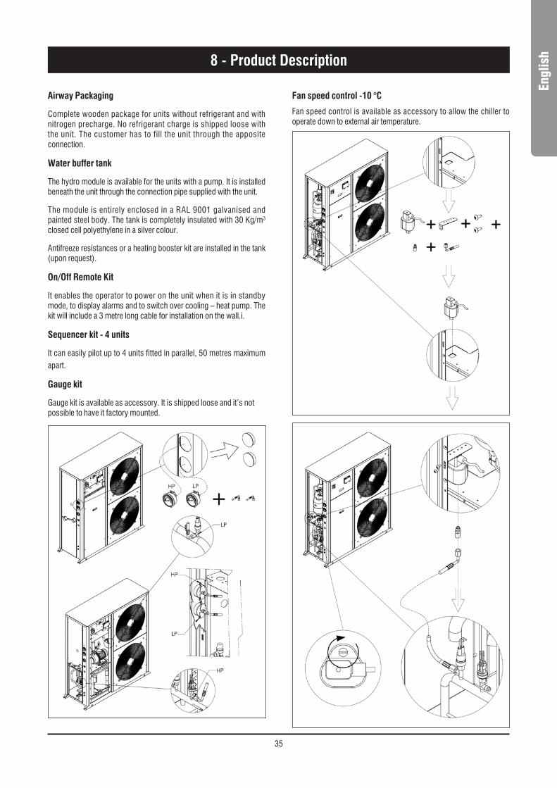
Fans Control
All models have a step speed controller as a standard. It will act according to the condensing pressure and allow the operation down to an Air temperature operation of +10 °C.
For 40-75 sizes refer to chapter 8.3.
Refrigerating Circuits
Each unit has a single refrigerating circuit equipped with an external service valves intended to measure the refrigerant pressure and charge, a sight glass with a humidity indicator, a dryer filter and a thermal expansion valve.
Refrigerating circuits are also complete with a high pressure switch as well as a high and low transducer.
Control Supply Panel
All components of the control system and those necessary to start the motors are shop connected and tested. The control compartment contains an electronic card and a control board with an external keyboard and display, to show the operational functions, as well as the intervention of the alarms and the working blocks.

34
8 - Product Description
8.2 Accessories AQL/AQH 20-35
Water Filter
1-1/2” filter is included in the supplied equipment.
It is supplied loose and has to be mounted by the customer.
Anti-Vibration Kit
Anti-vibration kit made of special rubber pad is provided together with the unit.
Water Differential Pressure Switch
Water differential pressure switch is mounted as standard in the unit.
Flow switch kit
Flow switch kit is available as an accessory. It is supplied loose and as to be mounted by the customer. Connect terminals 1-2 of the flow switch with terminals 1-2 of the Aqu@Logic electrical box.
Corrosion proofing protection for condensing
Two-level optional coil finishing :
1) Fin guard Silver.
2) Blue fins.
Intrusion proofing protection for condensing
A galvanised and painted steel wire net protection is assembled outside the unit.
Water Gauge
It is assembled on the unit as a standard.
Pump
Min. 100 kPa head pressure pump is mounted as a standard in the unit.
No pump kit
No pump kit is available as an accessory whenever the customer doesn’t need pump fitted in the unit.
Phase Monitor Kit
It is assembled on the unit as a standard.
35
Engl
ish8 - Product Description
Airway Packaging
Complete wooden package for units without refrigerant and with nitrogen precharge. No refrigerant charge is shipped loose with the unit. The customer has to fill the unit through the apposite connection.
Water buffer tank
The hydro module is available for the units with a pump. It is installed beneath the unit through the connection pipe supplied with the unit.
The module is entirely enclosed in a RAL 9001 galvanised and painted steel body. The tank is completely insulated with 30 Kg/m3 closed cell polyethylene in a silver colour.
Antifreeze resistances or a heating booster kit are installed in the tank (upon request).
On/Off Remote Kit
It enables the operator to power on the unit when it is in standby mode, to display alarms and to switch over cooling – heat pump. The kit will include a 3 metre long cable for installation on the wall.i.
Sequencer kit - 4 units
It can easily pilot up to 4 units fitted in parallel, 50 metres maximum apart.
Gauge kit
Gauge kit is available as accessory. It is shipped loose and it’s not possible to have it factory mounted.
Fan speed control -10 °C
Fan speed control is available as accessory to allow the chiller to operate down to external air temperature.

36
8 - Product Description
Add in the Control Board when install the Fan Speed Control
In/out valve kit
In/Out valve kit is available as accessory.
Parameters setting when install fan speed control

37
Engl
ish8 - Product Description
Water Filter
It is assembled on the unit as a standard.
Anti-Vibration Kit
See figure below.
Flow switch kit
It is assembled on the unit as a standard
Corrosion proofing protection for condensing
Two-level optional coil finishing
1) Fin guard Silver.
2) Blue fins.
Pump
The unit is available :
- without pump
8.3 Accessories AQL/AQH 40 to 75 - with 1 pump that guarantee 150 kPa of available static pressure;
- with 2 pumps that guarantee 150 kPa of available static pressure
Water buffer tank
The hydro module is available for the units with a pump; it is fitted inside and integrated in the circuit.
The module is entirely enclosed in a RAL 9001 galvanised and painted steel body.
The tank is covered with 10mm polyethylene insulation and it is provided with a 200W anti-freezing heater.
On/Off Remote kit
It enables the operator to power on the unit when it is in stand by mode, to display alarm and to switch over cooling – heat pump.
The kit will include a 3 metre long cable for installation on the wall.

38
8 - Product Description
Gauges kit
Gauges kit is available as accessory. It is shipped loose and it’s not possible to have it factory mounted.
Fan speed control
Fan speed control is available as accessory to allow the chiller to operate down to external air temperature.
In/Out valve kit
In/Out valve kit is available as accessory.

39
Engl
ish
8.4 Refrigerant flow diagram - AQL 20 to 35 - R410A
8 - Product Description
2
H
34
5
6
SHATA
OIL EQUAL. 1
E
CF
8 8
FS
NI
9
NL
10 8
SL BT
11
13
13
12
14
HYDROKIT
7
L
15
S
M
D
safety/control devicesa High pressure switch H Defrost temperature sensor
Pipe connection with Shrader valveat High pressure transducer i HydrometerBt Low pressure transducer l Vent valve ------- Optional partsc Water differential pressure switch m Discharge temperature sensor Sensorsd Air temperature sensor n Water safety valvee Outlet water temperature sensor s 5/16" Shrader valve (charging point)f Inlet water temperature sensor sH 5/16" high pressure Shrader valvefs Flow switch sl 5/16" low pressure Shrader valve
components1 Compressor tandem scroll type2 Air cooled condenser3 Filter drier4 Sight glass5 Thermostatic expansion valve6 Plate heat exchanger7 Pump8 Drain valve9 Water buffer tank
10 Water filter (supplied loose)11 Automatic water charging valve12 Water outlet13 Water inlet14 Water charging line15 Pressure expansion tank

40
8 - Product Description
3
2
OFF
H
45
67
8
BT SL
SHATAOIL EQUAL. 1
C
10
FS
NI
11
N
L
L
12 10
15
1514
16
13
HYDROKIT
10
917
S
F
E
D
M
safety/control devicesa High pressure switch H Defrost temperature sensor
Pipe connection with Shrader valveat High pressure transducer i HydrometerBt Low pressure transducer l Vent valve ------- Optional partsc Water differential pressure switch m Discharge temperature sensor Sensorsd Air temperature sensor n Water safety valvee Outlet water temperature sensor s 5/16" Shrader valve (charging point)f Inlet water temperature sensor sH 5/16" high pressure Shrader valvefs Flow switch sl 5/16" low pressure Shrader valve
components1 Compressor tandem scroll type2 4-way valve3 Air cooled condenser4 Biflow filter drier5 Sight glass6 Biflow thermostatic expansion valve7 Liquid receiver8 Plate heat exchanger9 Pump
10 Drain valve11 Water buffer tank12 Water filter (supplied loose)13 Automatic water charging valve14 Water outlet15 Water inlet16 Water charging line17 Pressure expansion tank
Refrigerant flow diagram - AQH 20 to 35 - R410A

41
Engl
ish8 - Product Description
Refrigerant flow diagram - AQL 40 to 75 - R410A
AQL R410A (Fluid group 2) :
safety/control devices Hazard cateGory / evaluation modulea High pressure switch (40.5 bar) 4 / mod. B+Dat High pressure transducerBt Low pressure transducerd Air temperature sensore Inlet water temperature sensorf Outlet water temperature sensorG Safety valve (45 bar) 4 / mod. H1m Discharge temperature sensors 5/16" SAE Schrader valve (charging point)sH 5/16" SAE high pressure Schrader valvesl 5/16" SAE low pressure Schrader valveH Thermometer
Pipe connection with Schrader valve 1/4" SAE
ProbesUnit side
----- Optional parts
components vessel cateGory (≥2)/evaluation module1 Compressor tandem scroll type 2 / mod. D12 Air cooled condenser3 Filter drier4 Sight glass5 Thermostatic expansion valve6 Plate heat exchanger 2 (sizes 60 to 75) / mod. B+D7 Water inlet8 Water outlet9 In/Out valve
10 Flexible pipes11 By-pass valve12 Desuperheater (optional)
2
34
5
6
SH ATA
OIL EQUAL. 1
SL BT
S
M
D
OUTLET
INLET
10
10 9
9
8
H
H
7
11
HYDR
AULI
C CI
RCUI
T
G
E
F
12
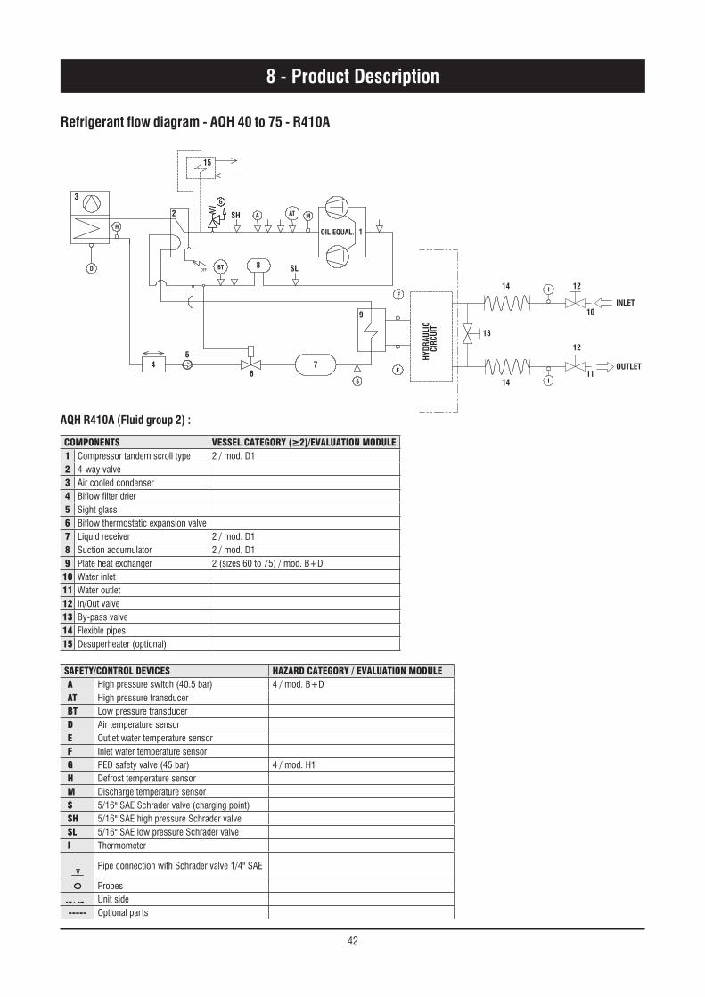
42
Refrigerant flow diagram - AQH 40 to 75 - R410A
8 - Product Description
safety/control devices Hazard cateGory / evaluation modulea High pressure switch (40.5 bar) 4 / mod. B+Dat High pressure transducerBt Low pressure transducerd Air temperature sensore Outlet water temperature sensorf Inlet water temperature sensorG PED safety valve (45 bar) 4 / mod. H1H Defrost temperature sensorm Discharge temperature sensors 5/16" SAE Schrader valve (charging point)sH 5/16" SAE high pressure Schrader valvesl 5/16" SAE low pressure Schrader valvei Thermometer
Pipe connection with Schrader valve 1/4" SAE
ProbesUnit side
----- Optional parts
components vessel cateGory (≥2)/evaluation module1 Compressor tandem scroll type 2 / mod. D12 4-way valve3 Air cooled condenser4 Biflow filter drier5 Sight glass6 Biflow thermostatic expansion valve7 Liquid receiver 2 / mod. D18 Suction accumulator 2 / mod. D19 Plate heat exchanger 2 (sizes 60 to 75) / mod. B+D
10 Water inlet11 Water outlet12 In/Out valve13 By-pass valve14 Flexible pipes15 Desuperheater (optional)
3
2
OFF
H
45
6
G
7
9
BT SL
SH ATA
OIL EQUAL. 1
S
F
E
D
M
HYDR
AULI
C CI
RCUI
T
13
10
I
I
11
12
1214
14
INLET
OUTLET
15
8
AQH R410A (Fluid group 2) :
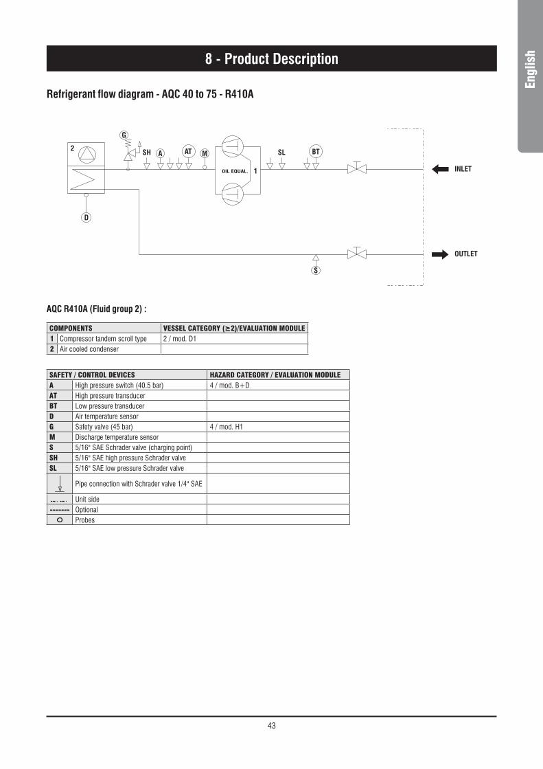
43
Engl
ish
Refrigerant flow diagram - AQC 40 to 75 - R410A
8 - Product Description
safety / control devices Hazard cateGory / evaluation modulea High pressure switch (40.5 bar) 4 / mod. B+Dat High pressure transducerBt Low pressure transducerd Air temperature sensorG Safety valve (45 bar) 4 / mod. H1m Discharge temperature sensors 5/16" SAE Schrader valve (charging point)sH 5/16" SAE high pressure Schrader valvesl 5/16" SAE low pressure Schrader valve
Pipe connection with Schrader valve 1/4" SAE
Unit side------- Optional
Probes
components vessel cateGory (≥2)/evaluation module1 Compressor tandem scroll type 2 / mod. D12 Air cooled condenser
A
G
SH
INLET
OUTLET
SL BT
S
D
1OIL EQUAL.
2 AT M
AQC R410A (Fluid group 2) :
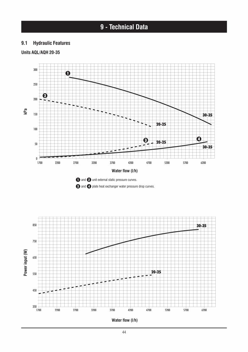
44
9.1 Hydraulic Features
Units AQL/AQH 20-35
9 - Technical Data
Water flow (l/h)
kPa
1700 0
50
100
150
200
250
300
2200 2700 3200 3700 4200 4700 5200
30-35
20-25
20-2530-35
5700 6200
1
2
3 4
350
450
550
650
750
850
1700 2200 2700 3200 3700 4200 4700 5200 5700 6200
20-25
30-35
Water flow (l/h)
Pow
er in
put (
W)
1 and 2 unit external static pressure curves.
3 and 4 plate heat exchanger water pressure drop curves.

45
Engl
ish9 - Technical Data
0
10
20
30
40
50
60
70
80
90
100
110
120
3000 4000 5000 6000 7000 8000 9000 10000 11000 12000 13000 14000 15000 16000 17000 18000
AQL/AQH 60-75
AQL/AQH 50
AQL/AQH 40-45
Water flow (l/h)
Water flow (l/h)
Pres
sure
dro
p (k
Pa)
Pres
sure
dro
p (k
Pa)
0102030405060708090
100110120130140150
AQL/AQH 65-75
AQL/AQH 50-60
AQL/AQH 40-45
1000 1500 2000 2500 3000 3500 4000 4500 5000
Evaporator water pressure drop - AQL/AQH 40 to 75 - R410A
Desuperheater water pressure drop - AQL/AQH 40 to 75 - R410A
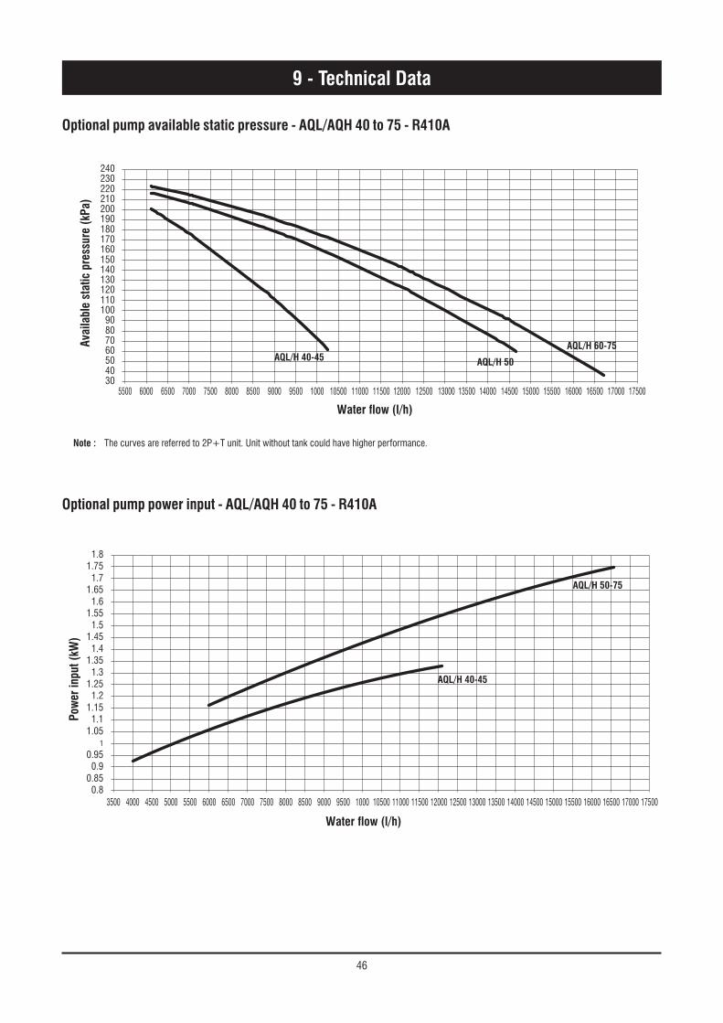
46
9 - Technical Data
Optional pump available static pressure - AQL/AQH 40 to 75 - R410A
Optional pump power input - AQL/AQH 40 to 75 - R410A
30405060708090
100110120130140150160170180190200210220230240
AQL/H 40-45AQL/H 60-75
AQL/H 50
5500 6000 6500 7000 7500 8000 8500 9000 9500 1000 10500 11000 11500 12000 12500 13000 13500 14000 14500 15000 15500 16000 16500 17000 17500
Water flow (l/h)
Avai
labl
e st
atic
pre
ssur
e (k
Pa)
Note : The curves are referred to 2P+T unit. Unit without tank could have higher performance.
0.83500 4000 4500 5000 5500 6000 6500 7000 7500 8000 8500 9000 9500 1000 10500 11000 11500 12000 12500 13000 13500 14000 14500 15000 15500 16000 16500 17000 17500
0.850.9
0.951
1.051.1
1.151.2
1.251.3
1.351.4
1.451.5
1.551.6
1.651.7
1.751.8
AQL/H 40-45
AQL/H 50-75
Water flow (l/h)
Pow
er in
put (
kW)
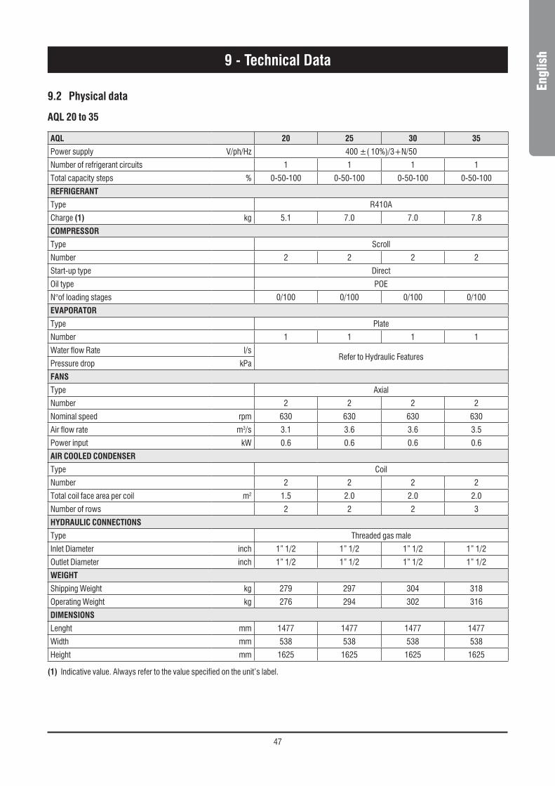
47
Engl
ish
AQL 20 25 30 35
Power supply V/ph/Hz 400 ±( 10%)/3+N/50
Number of refrigerant circuits 1 1 1 1
Total capacity steps % 0-50-100 0-50-100 0-50-100 0-50-100
REFRIGERANT
Type R410A
Charge (1) kg 5.1 7.0 7.0 7.8
COMPRESSOR
Type Scroll
Number 2 2 2 2
Start-up type Direct
Oil type POE
N°of loading stages 0/100 0/100 0/100 0/100
EVAPORATOR
Type Plate
Number 1 1 1 1
Water flow Rate l/sRefer to Hydraulic Features
Pressure drop kPa
FANS
Type Axial
Number 2 2 2 2
Nominal speed rpm 630 630 630 630
Air flow rate m3/s 3.1 3.6 3.6 3.5
Power input kW 0.6 0.6 0.6 0.6
AIR COOLED CONDENSER
Type Coil
Number 2 2 2 2
Total coil face area per coil m2 1.5 2.0 2.0 2.0
Number of rows 2 2 2 3
HYDRAULIC CONNECTIONS
Type Threaded gas male
Inlet Diameter inch 1” 1/2 1” 1/2 1” 1/2 1” 1/2
Outlet Diameter inch 1” 1/2 1” 1/2 1” 1/2 1” 1/2
WEIGHT
Shipping Weight kg 279 297 304 318
Operating Weight kg 276 294 302 316
DIMENSIONS
Lenght mm 1477 1477 1477 1477
Width mm 538 538 538 538
Height mm 1625 1625 1625 1625
9.2 Physical data
AQL 20 to 35
9 - Technical Data
(1) Indicative value. Always refer to the value specified on the unit’s label.

48
AQL 40 to 75 - BLN Version
AQL BLN 40 45 50 60 65 75Power supply V/ph/Hz 400V/3/50HzNumber of refrigerant circuits 1 1 1 1 1 1Total capacity steps % 0-50-100 0-50-100 0-50-100 0-44-56-100 0-50-100 0-50-100REFRIGERANTType R410ACharge (1) kg 9.5 10.7 11.9 14.3 15.5 17.9COMPRESSORType ScrollNumber 2 2 2 2 2 2Start-up type DirectOil type POEN°of loading stages 0/100 0/100 0/100 0/100 0/100 0/100EVAPORATORType PlateNumber 1 1 1 1 1 1Water flow rate l/s 1.9 2.1 2.4 2.9 3.2 3.6Pressure drop kPa Refer to Hydraulic featuresDESUPERHEATERType PlateNumber 1 1 1 1 1 1Water flow rate l/s 0.50 0.56 0.65 0.75 0.85 0.97Pressure drop kPa 18 21 21 24 22 26FANSType AxialNumber 1 1 1 1 1 1Nominal speed rpm 680 680 680 900 900 900Air flow rate m3/s 4 4 3.7 5.9 5.9 5.9Power input kW 0.98 0.98 0.98 2.00 2.00 2.00AIR COOLED CONDENSERType CoilNumber 1 1 1 1 1 1Total coil face area per coil m2 2.6 2.6 2.6 3.2 3.2 3.2Number of rows 2 2 3 3 3 3HYDRAULIC CONNECTIONS (EVAPORATOR)Type Threaded gas maleInlet diameter inch 2" 2" 2" 2" 2" 2"Outlet diameter inch 2" 2" 2" 2" 2" 2"HYDRAULIC CONNECTIONS (DESUPERHEATER)Type Threaded gas maleInlet diameter inch 1" 1" 1" 1" 1" 1"Outlet diameter inch 1" 1" 1" 1" 1" 1"WEIGHTShipping weight kg 403 411 436 476 483 488Operating weight kg 413 421 446 489 499 502DIMENSIONSLength mm 1750 1750 1750 2200 2200 2200Width mm 1100 1100 1100 1100 1100 1100Height mm 1580 1580 1580 1580 1580 1580
9 - Technical Data
(1) Indicative value. Always refer to the value specified on the unit’s label.

49
Engl
ish
AQL 40 to 75 - ELN Version
AQL ELN 40 45 50 60 65 75Power supply V/ph/Hz 400V/3/50HzNumber of refrigerant circuits 1 1 1 1 1 1Total capacity steps % 0-50-100 0-50-100 0-50-100 0-44-56-100 0-50-100 0-50-100REFRIGERANTType R410ACharge (1) kg 9.5 10.7 11.9 14.3 15.5 17.9COMPRESSORType ScrollNumber 2 2 2 2 2 2Start-up type DirectOil type POEN°of loading stages 0/100 0/100 0/100 0/100 0/100 0/100EVAPORATORType PlateNumber 1 1 1 1 1 1Water flow rate l/s 1.8 2.0 2.3 2.8 3.0 3.5Pressure drop kPa Refer to Hydraulic featuresDESUPERHEATERType PlateNumber 1 1 1 1 1 1Water flow rate l/s 0.50 0.55 0.64 0.74 0.81 0.95Pressure drop kPa 17 21 20 23 20 26FANSType AxialNumber 1 1 1 1 1 1Nominal speed rpm 530 530 530 720 720 720Air flow rate m³/s 3.05 3.05 2.86 4.4 4.4 4.4Power input kW 0.57 0.57 0.57 1.27 1.27 1.27AIR COOLED CONDENSERType CoilNumber 1 1 1 1 1 1Total coil face area per coil m2 2.6 2.6 2.6 3.2 3.2 3.2Number of rows 2 2 3 3 3 3HYDRAULIC CONNECTIONS (EVAPORATOR)Type Threaded gas maleInlet diameter inch 2" 2" 2" 2" 2" 2"Outlet diameter inch 2" 2" 2" 2" 2" 2"HYDRAULIC CONNECTIONS (DESUPERHEATER)Type Threaded gas maleInlet diameter inch 1" 1" 1" 1" 1" 1"Outlet diameter inch 1" 1" 1" 1" 1" 1"WEIGHTShipping weight kg 403 411 436 476 483 488Operating weight kg 413 421 446 489 499 502DIMENSIONSLength mm 1750 1750 1750 2200 2200 2200Width mm 1100 1100 1100 1100 1100 1100Height mm 1580 1580 1580 1580 1580 1580
9 - Technical Data
(1) Indicative value. Always refer to the value specified on the unit’s label.
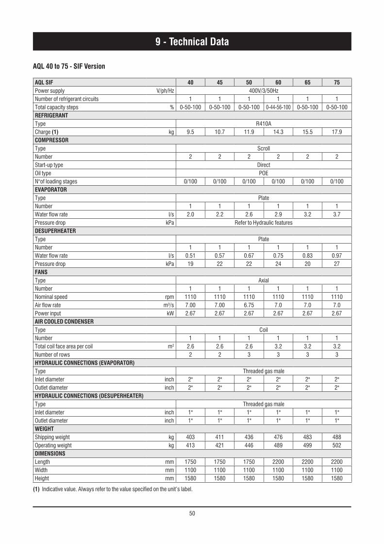
50
AQL 40 to 75 - SIF Version
AQL SIF 40 45 50 60 65 75Power supply V/ph/Hz 400V/3/50HzNumber of refrigerant circuits 1 1 1 1 1 1Total capacity steps % 0-50-100 0-50-100 0-50-100 0-44-56-100 0-50-100 0-50-100REFRIGERANTType R410ACharge (1) kg 9.5 10.7 11.9 14.3 15.5 17.9COMPRESSORType ScrollNumber 2 2 2 2 2 2Start-up type DirectOil type POEN°of loading stages 0/100 0/100 0/100 0/100 0/100 0/100EVAPORATORType PlateNumber 1 1 1 1 1 1Water flow rate l/s 2.0 2.2 2.6 2.9 3.2 3.7Pressure drop kPa Refer to Hydraulic featuresDESUPERHEATERType PlateNumber 1 1 1 1 1 1Water flow rate l/s 0.51 0.57 0.67 0.75 0.83 0.97Pressure drop kPa 19 22 22 24 20 27FANSType AxialNumber 1 1 1 1 1 1Nominal speed rpm 1110 1110 1110 1110 1110 1110Air flow rate m³/s 7.00 7.00 6.75 7.0 7.0 7.0Power input kW 2.67 2.67 2.67 2.67 2.67 2.67AIR COOLED CONDENSERType CoilNumber 1 1 1 1 1 1Total coil face area per coil m2 2.6 2.6 2.6 3.2 3.2 3.2Number of rows 2 2 3 3 3 3HYDRAULIC CONNECTIONS (EVAPORATOR)Type Threaded gas maleInlet diameter inch 2" 2" 2" 2" 2" 2"Outlet diameter inch 2" 2" 2" 2" 2" 2"HYDRAULIC CONNECTIONS (DESUPERHEATER)Type Threaded gas maleInlet diameter inch 1" 1" 1" 1" 1" 1"Outlet diameter inch 1" 1" 1" 1" 1" 1"WEIGHTShipping weight kg 403 411 436 476 483 488Operating weight kg 413 421 446 489 499 502DIMENSIONSLength mm 1750 1750 1750 2200 2200 2200Width mm 1100 1100 1100 1100 1100 1100Height mm 1580 1580 1580 1580 1580 1580
9 - Technical Data
(1) Indicative value. Always refer to the value specified on the unit’s label.
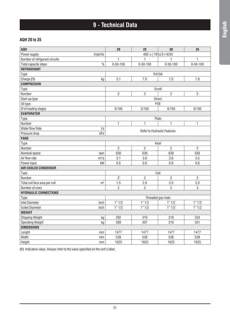
51
Engl
ish
AQH 20 to 35
AQH 20 25 30 35Power supply V/ph/Hz 400 ±( 10%)/3+N/50Number of refrigerant circuits 1 1 1 1Total capacity steps % 0-50-100 0-50-100 0-50-100 0-50-100REFRIGERANTType R410ACharge (1) kg 5.1 7.0 7.0 7.8COMPRESSORType ScrollNumber 2 2 2 2Start-up type DirectOil type POEN°of loading stages 0/100 0/100 0/100 0/100EVAPORATORType PlateNumber 1 1 1 1Water flow Rate l/s
Refer to Hydraulic FeaturesPressure drop kPaFANSType AxialNumber 2 2 2 2Nominal speed rpm 630 630 630 630Air flow rate m3/s 3.1 3.6 3.6 3.5Power input kW 0.6 0.6 0.6 0.6AIR COOLED CONDENSERType CoilNumber 2 2 2 2Total coil face area per coil m2 1.5 2.0 2.0 2.0Number of rows 2 2 2 3HYDRAULIC CONNECTIONSType Threaded gas maleInlet Diameter inch 1” 1/2 1” 1/2 1” 1/2 1” 1/2Outlet Diameter inch 1” 1/2 1” 1/2 1” 1/2 1” 1/2WEIGHTShipping Weight kg 292 310 318 333Operating Weight kg 289 307 316 331DIMENSIONSLenght mm 1477 1477 1477 1477Width mm 538 538 538 538Height mm 1625 1625 1625 1625
9 - Technical Data
(1) Indicative value. Always refer to the value specified on the unit’s label.

52
AQH 40 to 75 - BLN Version
AQH BLN 40 45 50 60 65 75Power supply V/ph/Hz 400V/3/50HzNumber of refrigerant circuits 1 1 1 1 1 1Total capacity steps % 0-50-100 0-50-100 0-50-100 0-44-56-100 0-50-100 0-50-100REFRIGERANTType R410ACharge (1) kg 9.5 10.7 11.9 14.3 15.5 17.9COMPRESSORType ScrollNumber 2 2 2 2 2 2Start-up type DirectOil type POEN°of loading stages 0/100 0/100 0/100 0/100 0/100 0/100EVAPORATORType PlateNumber 1 1 1 1 1 1Water flow rate l/s 1.9 2.1 2.4 2.9 3.2 3.6Pressure drop kPa Refer to Hydraulic featuresDESUPERHEATERType PlateNumber 1 1 1 1 1 1Water flow rate l/s 0.51 0.57 0.67 0.75 0.83 0.97Pressure drop kPa 19 22 22 24 20 27FANSType AxialNumber 1 1 1 1 1 1Nominal speed rpm 680 680 680 900 900 900Air flow rate m³/s 4.1 4.1 4.1 6.2 6.2 6.2Power input kW 0.98 0.98 0.98 2.00 2.00 2.00AIR COOLED CONDENSERType CoilNumber 1 1 1 1 1 1Total coil face area per coil m2 2.6 2.6 2.6 3.2 3.2 3.2Number of rows 2 2 3 3 3 3HYDRAULIC CONNECTIONS (EVAPORATOR)Type Threaded gas maleInlet diameter inch 2" 2" 2" 2" 2" 2"Outlet diameter inch 2" 2" 2" 2" 2" 2"HYDRAULIC CONNECTIONS (DESUPERHEATER)Type Threaded gas maleInlet diameter inch 1" 1" 1" 1" 1" 1"Outlet diameter inch 1" 1" 1" 1" 1" 1"WEIGHTShipping weight kg 422 430 457 504 511 517Operating weight kg 431 440 467 517 524 530DIMENSIONSLength mm 1750 1750 1750 2200 2200 2200Width mm 1100 1100 1100 1100 1100 1100Height mm 1580 1580 1580 1580 1580 1580
9 - Technical Data
(1) Indicative value. Always refer to the value specified on the unit’s label.

53
Engl
ish
AQH 40 to 75 - ELN Version
AQH ELN 40 45 50 60 65 75Power supply V/ph/Hz 400V/3/50HzNumber of refrigerant circuits 1 1 1 1 1 1Total capacity steps % 0-50-100 0-50-100 0-50-100 0-44-56-100 0-50-100 0-50-100REFRIGERANTType R410ACharge (1) kg 9.5 10.7 11.9 14.3 15.5 17.9COMPRESSORType ScrollNumber 2 2 2 2 2 2Start-up type DirectOil type POEN°of loading stages 0/100 0/100 0/100 0/100 0/100 0/100EVAPORATORType PlateNumber 1 1 1 1 1 1Water flow rate l/s 1.8 2.0 2.3 2.8 3.0 3.5Pressure drop kPa Refer to Hydraulic featuresDESUPERHEATERType PlateNumber 1 1 1 1 1 1Water flow rate l/s 0.50 0.55 0.64 0.74 0.81 0.95Pressure drop kPa 17 21 20 23 20 26FANSType AxialNumber 1 1 1 1 1 1Nominal speed rpm 530 530 530 720 720 720Air flow rate m³/s 3.2 3.2 3 4.7 4.7 4.7Power input kW 0.57 0.57 0.57 1.27 1.27 1.27AIR COOLED CONDENSERType CoilNumber 1 1 1 1 1 1Total coil face area per coil m2 2.6 2.6 2.6 3.2 3.2 3.2Number of rows 2 2 3 3 3 3HYDRAULIC CONNECTIONS (EVAPORATOR)Type Threaded gas maleInlet diameter inch 2" 2" 2" 2" 2" 2"Outlet diameter inch 2" 2" 2" 2" 2" 2"HYDRAULIC CONNECTIONS (DESUPERHEATER)Type Threaded gas maleInlet diameter inch 1" 1" 1" 1" 1" 1"Outlet diameter inch 1" 1" 1" 1" 1" 1"WEIGHTShipping weight kg 422 430 457 504 511 517Operating weight kg 431 440 467 517 524 530DIMENSIONSLength mm 1750 1750 1750 2200 2200 2200Width mm 1100 1100 1100 1100 1100 1100Height mm 1580 1580 1580 1580 1580 1580
9 - Technical Data
(1) Indicative value. Always refer to the value specified on the unit’s label.

54
AQH 40 to 75 - SIF Version
AQH SIF 40 45 50 60 65 75Power supply V/ph/Hz 400V/3/50HzNumber of refrigerant circuits 1 1 1 1 1 1Total capacity steps % 0-50-100 0-50-100 0-50-100 0-44-56-100 0-50-100 0-50-100REFRIGERANTType R410ACharge (1) kg 9.5 10.7 11.9 14.3 15.5 17.9COMPRESSORType ScrollNumber 2 2 2 2 2 2Start-up type DirectOil type POEN°of loading stages 0/100 0/100 0/100 0/100 0/100 0/100EVAPORATORType PlateNumber 1 1 1 1 1 1Water flow rate l/s 2.0 2.2 2.6 2.9 3.2 3.7Pressure drop kPa Refer to Hydraulic featuresDESUPERHEATERType PlateNumber 1 1 1 1 1 1Water flow rate l/s 0.51 0.57 0.67 0.75 0.83 0.97Pressure drop kPa 19 22 22 24 20 27FANSType AxialNumber 1 1 1 1 1 1Nominal speed rpm 1110 1110 1110 1110 1110 1110Air flow rate m³/s 7 7 6.75 7 7 7Power input kW 2.67 2.67 2.67 2.67 2.67 2.67AIR COOLED CONDENSERType CoilNumber 1 1 1 1 1 1Total coil face area per coil m2 2.6 2.6 2.6 3.2 3.2 3.2Number of rows 2 2 3 3 3 3HYDRAULIC CONNECTIONS (EVAPORATOR)Type Threaded gas maleInlet diameter inch 2" 2" 2" 2" 2" 2"Outlet diameter inch 2" 2" 2" 2" 2" 2"HYDRAULIC CONNECTIONS (DESUPERHEATER)Type Threaded gas maleInlet diameter inch 1" 1" 1" 1" 1" 1"Outlet diameter inch 1" 1" 1" 1" 1" 1"WEIGHTShipping weight kg 422 430 457 504 511 517Operating weight kg 431 440 467 517 524 530DIMENSIONSLength mm 1750 1750 1750 2200 2200 2200Width mm 1100 1100 1100 1100 1100 1100Height mm 1580 1580 1580 1580 1580 1580
9 - Technical Data
(1) Indicative value. Always refer to the value specified on the unit’s label.

55
Engl
ish
AQC 40 to 75 - BLN Version
9 - Technical Data
AQC BLN 40 45 50 60 65 75
Power supply V/ph/Hz 400V/3/50Hz
Number of refrigerant circuits 1 1 1 1 1 1
Total capacity steps % 0-50-100 0-50-100 0-50-100 0-44-56-100 0-50-100 0-50-100
REFRIGERANT
Type R410A
COMPRESSOR
Type Scroll
Number 2 2 2 2 2 2
Start-up type Direct
Oil type POE
N°of loading stages 0/100 0/100 0/100 0/100 0/100 0/100
FANS
Type Axial
Number 1 1 1 1 1 1
Nominal speed rpm 680 680 680 900 900 900
Air flow rate m³/s 4 4 3.7 5.9 5.9 5.9
Power input kW 0.98 0.98 0.98 2.00 2.00 2.00
AIR COOLED CONDENSER
Type Coil
Number 1 1 1 1 1 1
Total coil face area per coil m² 2.6 2.6 2.6 3.2 3.2 3.2
Number of rows 2 2 3 3 3 3
REFRIGERANT CONNECTIONS
Inlet diameter inch 5/8" 5/8" 5/8" 7/8" 7/8" 7/8"
Outlet diameter inch 1"3/8 1"3/8 1"3/8 1"3/8 1"3/8 1"3/8
WEIGHT
Shipping weight kg 391 399 422 456 466 469
DIMENSIONS
Length mm 1750 1750 1750 2200 2200 2200
Width mm 1100 1100 1100 1100 1100 1100
Height mm 1580 1580 1580 1580 1580 1580

56
9 - Technical Data
AQC ELN 40 45 50 60 65 75
Power supply V/ph/Hz 400V/3/50Hz
Number of refrigerant circuits 1 1 1 1 1 1
Total capacity steps % 0-50-100 0-50-100 0-50-100 0-44-56-100 0-50-100 0-50-100
REFRIGERANT
Type R410A
COMPRESSOR
Type Scroll
Number 2 2 2 2 2 2
Start-up type Direct
Oil type POE
N°of loading stages 0/100 0/100 0/100 0/100 0/100 0/100
FANS
Type Axial
Number 1 1 1 1 1 1
Nominal speed rpm 530 530 530 720 720 720
Air flow rate m³/s 3 3 2.9 4.4 4.4 4.4
Power input kW 0.57 0.57 0.57 1.27 1.27 1.27
AIR COOLED CONDENSER
Type Coil
Number 1 1 1 1 1 1
Total coil face area per coil m² 2.6 2.6 2.6 3.2 3.2 3.2
Number of rows 2 2 3 3 3 3
REFRIGERANT CONNECTIONS
Inlet diameter inch 5/8" 5/8" 5/8" 7/8" 7/8" 7/8"
Outlet diameter inch 1"3/8 1"3/8 1"3/8 1"3/8 1"3/8 1"3/8
WEIGHT
Shipping weight kg 391 399 422 456 466 469
DIMENSIONS
Length mm 1750 1750 1750 2200 2200 2200
Width mm 1100 1100 1100 1100 1100 1100
Height mm 1580 1580 1580 1580 1580 1580
AQC 40 to 75 - ELN Version

57
Engl
ish9 - Technical Data
AQC SIF 40 45 50 60 65 75
Power supply V/ph/Hz 400V/3/50Hz
Number of refrigerant circuits 1 1 1 1 1 1
Total capacity steps % 0-50-100 0-50-100 0-50-100 0-44-56-100 0-50-100 0-50-100
REFRIGERANT
Type R410A
COMPRESSOR
Type Scroll
Number 2 2 2 2 2 2
Start-up type Direct
Oil type POE
N°of loading stages 0/100 0/100 0/100 0/100 0/100 0/100
FANS
Type Axial
Number 1 1 1 1 1 1
Nominal speed rpm 1110 1110 1110 1110 1110 1110
Air flow rate m³/s 7.0 7.0 6.8 7.0 7.0 7.0
Power input kW 2.67 2.67 2.67 2.67 2.67 2.67
AIR COOLED CONDENSER
Type Coil
Number 1 1 1 1 1 1
Total coil face area per coil m² 2.6 2.6 2.6 3.2 3.2 3.2
Number of rows 2 2 3 3 3 3
REFRIGERANT CONNECTIONS
Inlet diameter inch 5/8" 5/8" 5/8" 7/8" 7/8" 7/8"
Outlet diameter inch 1"3/8 1"3/8 1"3/8 1"3/8 1"3/8 1"3/8
WEIGHT
Shipping weight kg 391 399 422 456 466 469
DIMENSIONS
Length mm 1750 1750 1750 2200 2200 2200
Width mm 1100 1100 1100 1100 1100 1100
Height mm 1580 1580 1580 1580 1580 1580
AQC 40 to 75 - SIF Version
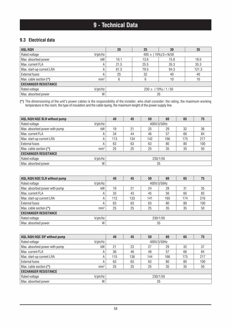
58
AQL/AQH 20 25 30 35Rated voltage V/ph/Hz 400 ± ( 10%)/3+N/50Max. absorbed power kW 10.1 13.6 15.8 18.0Max. current FLA A 21.5 25.5 35.3 35.3Max. start-up current LRA A 61.5 79.5 94.3 121.3External fuses A 25 32 40 40Max. cable section (*) mm2 6 6 10 10ExCHANGER RESISTANCERated voltage V/ph/Hz 230 ± ( 10%) / 1 / 50Max. absorbed power W 35
AQL/AQH/AQC BLN without pump 40 45 50 60 65 75Rated voltage V/ph/Hz 400V/3/50HzMax. absorbed power with pump kW 19 21 25 29 32 36Max. current FLA A 34 44 46 57 66 84Max. start-up current LRA A 113 134 142 166 175 217External fuses A 63 63 63 80 80 100Max. cable section (*) mm2 25 25 25 35 35 50ExCHANGER RESISTANCERated voltage V/ph/Hz 230/1/50Max. absorbed power W 35
AQL/AQH/AQC ELN without pump 40 45 50 60 65 75Rated voltage V/ph/Hz 400V/3/50HzMax. absorbed power with pump kW 19 21 24 28 31 35Max. current FLA A 33 43 45 56 65 83Max. start-up current LRA A 112 133 141 165 174 216External fuses A 63 63 63 80 80 100Max. cable section (*) mm2 25 25 25 35 35 50ExCHANGER RESISTANCERated voltage V/ph/Hz 230/1/50Max. absorbed power W 35
AQL/AQH/AQC SIF without pump 40 45 50 60 65 75Rated voltage V/ph/Hz 400V/3/50HzMax. absorbed power with pump kW 21 23 27 29 32 37Max. current FLA A 36 46 48 57 66 84Max. start-up current LRA A 115 136 144 166 175 217External fuses A 63 63 63 80 80 100Max. cable section (*) mm2 25 25 25 35 35 50ExCHANGER RESISTANCERated voltage V/ph/Hz 230/1/50Max. absorbed power W 35
9 - Technical Data
(*) The dimensioning of the unit’s power cables is the responsibility of the installer, who shall consider: the rating, the maximum working temperature in the room, the type of insulation and the cable laying, the maximum lenght of the power supply line.
9.3 Electrical data
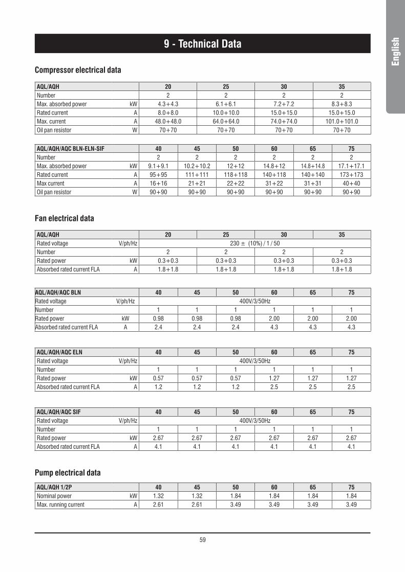
59
Engl
ish
Compressor electrical data
AQL/AQH 20 25 30 35Number 2 2 2 2Max. absorbed power kW 4.3+4.3 6.1+6.1 7.2+7.2 8.3+8.3Rated current A 8.0+8.0 10.0+10.0 15.0+15.0 15.0+15.0Max. current A 48.0+48.0 64.0+64.0 74.0+74.0 101.0+101.0Oil pan resistor W 70+70 70+70 70+70 70+70
Pump electrical data
AQL/AQH 1/2P 40 45 50 60 65 75 Nominal power kW 1.32 1.32 1.84 1.84 1.84 1.84Max. running current A 2.61 2.61 3.49 3.49 3.49 3.49
AQL/AQH/AQC BLN-ELN-SIF 40 45 50 60 65 75Number 2 2 2 2 2 2Max. absorbed power kW 9.1+9.1 10.2+10.2 12+12 14.8+12 14.8+14.8 17.1+17.1Rated current A 95+95 111+111 118+118 140+118 140+140 173+173Max current A 16+16 21+21 22+22 31+22 31+31 40+40Oil pan resistor W 90+90 90+90 90+90 90+90 90+90 90+90
AQL/AQH/AQC BLN 40 45 50 60 65 75Rated voltage V/ph/Hz 400V/3/50HzNumber 1 1 1 1 1 1Rated power kW 0.98 0.98 0.98 2.00 2.00 2.00Absorbed rated current FLA A 2.4 2.4 2.4 4.3 4.3 4.3
AQL/AQH/AQC ELN 40 45 50 60 65 75Rated voltage V/ph/Hz 400V/3/50HzNumber 1 1 1 1 1 1Rated power kW 0.57 0.57 0.57 1.27 1.27 1.27Absorbed rated current FLA A 1.2 1.2 1.2 2.5 2.5 2.5
AQL/AQH/AQC SIF 40 45 50 60 65 75Rated voltage V/ph/Hz 400V/3/50HzNumber 1 1 1 1 1 1Rated power kW 2.67 2.67 2.67 2.67 2.67 2.67Absorbed rated current FLA A 4.1 4.1 4.1 4.1 4.1 4.1
Fan electrical data
AQL/AQH 20 25 30 35Rated voltage V/ph/Hz 230 ± (10%) / 1 / 50Number 2 2 2 2Rated power kW 0.3+0.3 0.3+0.3 0.3+0.3 0.3+0.3Absorbed rated current FLA A 1.8+1.8 1.8+1.8 1.8+1.8 1.8+1.8
9 - Technical Data

60
9.4 Position of shock absorbers and weight distribution on supports
* Dimensions are referred to unit with antivibration mounted isolators.
P1 - P4 Unit positions
AQL AQH AQC
Weight distribution
Oper
ating
we
ight (
kg)
Shipp
ing
weigh
t (kg
) P1-P4 Coordinates* Weight distribution
Oper
ating
we
ight (
kg)
Shipp
ing
weigh
t (kg
) P1-P4 Coordinates* Weight distribution
Shipp
ing
weigh
t (kg
) P1-P4 Coordinates*
P1(kg)
P2(kg)
P3(kg)
P4(kg)
a(mm)
b(mm)
P1(kg)
P2(kg)
P3(kg)
P4(kg)
a(mm)
b(mm)
P1(kg)
P2(kg)
P3(kg)
P4(kg)
a(mm)
b(mm)
40 120 113 87 93 413 403 1054 1977 126 120 89 96 431 422 1054 1977 114 108 81 88 391 1054 1977
45 123 117 87 94 421 411 1054 1977 130 123 90 97 440 430 1054 1977 117 111 82 88 399 1054 1977
50 130 120 93 103 446 436 1054 1977 137 127 96 106 467 457 1054 1977 123 113 88 98 422 1054 1977
60 150 138 94 106 489 476 1054 1977 161 149 98 110 517 504 1054 1977 141 129 87 99 456 1054 1977
65 143 131 105 117 496 483 1054 1977 153 141 109 121 524 511 1054 1977 134 122 99 111 466 1054 1977
75 144 132 107 118 502 488 1054 1977 155 143 110 122 530 517 1054 1977 135 123 100 112 469 1054 1977
40 1P 121 115 104 110 450 434 1054 1977 127 121 107 113 468 453 1054 1977
45 1P 124 118 105 111 458 442 1054 1977 131 124 107 114 476 461 1054 1977
50 1P 132 122 111 121 486 470 1054 1977 140 130 114 123 507 490 1054 1977
60 1P 143 132 124 136 535 516 1054 1977 153 142 128 140 563 545 1054 1977
65 1P 145 134 126 137 542 523 1054 1977 157 145 128 140 570 552 1054 1977
75 1P 145 134 126 137 548 529 1054 1977 159 148 129 140 576 557 1054 1977
40 2P 129 122 110 117 478 460 1054 1977 135 128 113 120 497 479 1054 1977
45 2P 132 126 111 118 487 468 1054 1977 139 132 114 121 505 487 1054 1977
50 2P 140 130 119 129 518 499 1054 1977 148 138 121 131 538 520 1054 1977
60 2P 151 139 131 143 565 544 1054 1977 162 149 135 147 593 572 1054 1977
65 2P 153 141 133 145 572 551 1054 1977 165 153 135 147 600 579 1054 1977
75 2P 153 141 132 145 578 556 1054 1977 168 156 135 147 606 585 1054 1977
40 1P+T 141 135 152 159 587 476 1054 1977 148 141 155 162 606 494 1054 1977
45 1P+T 144 138 153 159 595 484 1054 1977 151 144 156 162 614 503 1054 1977
50 1P+T 152 142 160 170 623 512 1054 1977 159 150 163 172 644 532 1054 1977
60 1P+T 175 163 195 207 740 572 1054 1977 185 172 200 212 769 600 1054 1977
65 1P+T 179 167 195 207 748 579 1054 1977 188 175 200 212 776 607 1054 1977
75 1P+T 180 168 197 208 753 585 1054 1977 190 178 200 213 781 613 1054 1977
40 2P+T 146 139 157 164 607 495 1054 1977 152 145 160 167 625 513 1054 1977
45 2P+T 149 143 158 165 615 503 1054 1977 156 149 161 168 633 522 1054 1977
50 2P+T 157 147 166 176 646 534 1054 1977 165 155 168 179 667 554 1054 1977
60 2P+T 181 169 201 214 765 595 1054 1977 191 177 206 219 793 623 1054 1977
65 2P+T 184 172 202 214 772 602 1054 1977 194 181 206 219 800 631 1054 1977
75 2P+T 186 174 203 215 778 608 1054 1977 196 183 206 219 806 636 1054 1977
9 - Technical Data
a
b
P1 P2
P4 P3
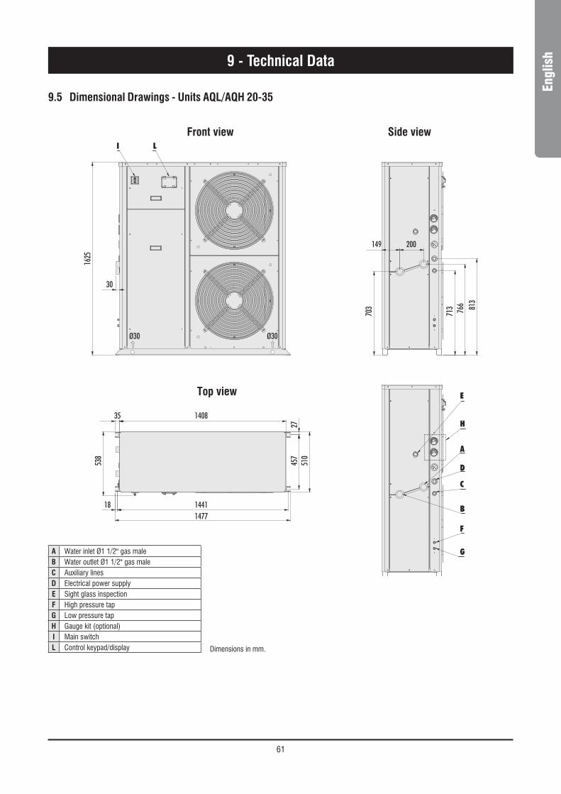
61
Engl
ish
9.5 Dimensional Drawings - Units AQL/AQH 20-35
9 - Technical Data
Front view Side view
Top view
Dimensions in mm.
1408
149 200
Ø30
30
I L
E
H
A
D
C
B
F
G
Ø30
35
1441
457
703
713 766 813
27
538
1625
510
18 1477
A Water inlet Ø1 1/2" gas maleB Water outlet Ø1 1/2" gas maleC Auxiliary linesD Electrical power supplyE Sight glass inspectionF High pressure tapG Low pressure tapH Gauge kit (optional)I Main switchL Control keypad/display

62
Dimensional Drawings - Units AQL/AQH 40-50
9 - Technical Data
1355
1395 16
8515
80
C
D
4 x Ø22
1100
2310
5423
1750
517
112 1121527
987
987
1100
P2
P1
P3
P4
50 1000 50
25
IL
H
F
G
250
950
470
730
188
A
B
E
N
M
2310
5423 112 1527 112
P3
P4
P2
P1 4 x Ø10
678
Front view
Bottom view
Side view Top view
A Water inlet Ø2" gas male F High pressure tapB Water outlet Ø2" gas male G Low pressure tapC Electrical auxiliary lines H Gauge kit (accessory)D Electrical power supply I Main switchE Hydrometer L Control keypad/display
M Desuperheater water inlet Ø1" gas male (optional)N Desuperheater water outlet Ø1" gas male (optional)
xxx Only for SIF fan modelP1, P2, P3, P4 AVM position
Dimensions in mm.

63
Engl
ish9 - Technical Data
Dimensional Drawings - Units AQL/AQH 60-75
50 1000 50
25
L I
H
F
G
250
950
730
470
188
A
E
B
N
M
1355
1395 16
85
1580
C
D
4 x Ø22
112 1977 112
2323
1054
P2
P1
P3
P44 x Ø10
987
1121977
2200
698
987
2310
5423
1100
112
1100
P2
P3
P1
P4
763
Front view
Bottom view
Side view Top view
A Water inlet Ø2" gas male F High pressure tapB Water outlet Ø2" gas male G Low pressure tapC Electrical auxiliary lines H Gauge kit (accessory)D Electrical power supply I Main switchE Hydrometer L Control keypad/display
M Desuperheater water inlet Ø1" gas male (optional)N Desuperheater water outlet Ø1" gas male (optional)
xxx Only for SIF fan modelP1, P2, P3, P4 AVM position
Dimensions in mm.

64
1355
1395 16
8515
80
C
D
4 x Ø22
1100
2310
5423
1750
517
112 1121527
987
987
1100
P2
P1
P3
P4
50 1000 50
25
IL
H
F
G
61275
2310
5423 112 1527 112
P3
P4
P2
P1 4 x Ø10
Q R
241
Front view
Bottom view
Side view Top view
C Electrical auxiliary linesD Electrical power supplyF High pressure tapG Low pressure tapH Gauge kit (accessory)I Main switchL Control keypad/display
xxx Only for SIF fan modelP1, P2, P3, P4 AVM position
Q Liquid line Ø 5/8"R Suction line Ø 1 3/8"
9 - Technical Data
Dimensional Drawings - Units AQC 40 to 50 - R410A
Dimensions in mm.

65
Engl
ish9 - Technical Data
Dimensional Drawings - Units AQC 60 to 75 - R410A
50 1000 50
25
L I
H
F
G
69875
1355
1395 16
85
1580
C
D
4 x Ø22
112 1977 112
2323
1054
P2
P1
P3
P44 x Ø10
987
1121977
2200
698
987
2310
5423
1100
112
1100
P2
P3
P1
P4241
Q R
Front view
Bottom view
Side view Top view
C Electrical auxiliary linesD Electrical power supplyF High pressure tapG Low pressure tapH Gauge kit (accessory)I Main switchL Control keypad/display
xxx Only for SIF fan modelP1, P2, P3, P4 AVM position
Q Liquid line Ø 7/8"R Suction line Ø 1 3/8"
Dimensions in mm.

66
9.6 Space Requirements
Units AQL/AQH/AQC 40 to 75
Units AQL/AQH 20 to 35
9 - Technical Data
800 mm400 mm
200 mm
200 mm
3000 mm
200 mm
1000 mm
1000 mm1000 mm
1000 mm
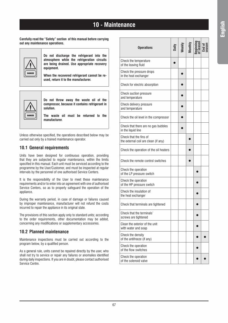
67
Engl
ish10 - Maintenance
Carefully read the “Safety” section of this manual before carrying out any maintenance operations.
DANGER
Do not discharge the refrigerant into the atmosphere while the refrigeration circuits are being drained. Use appropriate recovery equipment.
When the recovered refrigerant cannot be re-used, return it to the manufacturer.
DANGER
Do not throw away the waste oil of the compressor, because it contains refrigerant in solution.
The waste oil must be returned to the manufacturer.
Unless otherwise specified, the operations described below may be carried out only by a trained maintenance operator.
10.1 General requirements
Units have been designed for continuous operation, providing that they are subjected to regular maintenance, within the limits specified in this manual. Each unit must be serviced according to the programme by the User/Customer, and must be inspected at regular intervals by the personnel of one authorised Service Centers.
It is the responsibility of the User to meet these maintenance requirements and/or to enter into an agreement with one of authorised Service Centers, so as to properly safeguard the operation of the appliance.
During the warranty period, in case of damage or failures caused by improper maintenance, manufacturer will not refund the costs incurred to repair the appliance in its original state.
The provisions of this section apply only to standard units; according to the order requirements, other documentation may be added, concerning any modifications or supplementary accessories.
10.2 Planned maintenance
Maintenance inspections must be carried out according to the program below, by a qualified person.
As a general rule, units cannot be repaired directly by the user, who shall not try to service or repair any failures or anomalies identified during daily inspections. If you are in doubt, please contact authorised Service Centre.
Operations
Daily
Wee
kly
Mon
thly
Begi
nnin
g of
sea
son
End
of
seas
on
Check the temperatureof the leaving fluid •Check the pressure dropsin the heat exchanger •Check for electric absorption •Check suction pressureand temperature •Check delivery pressureand temperature •Check the oil level in the compressor •Check that there are no gas bubbles in the liquid line •Check that the fins ofthe external coil are clean (if any) •Check the operation of the oil heaters •Check the remote control switches •Check the operationof the LP pressure switch •Check the operationof the HP pressure switch •Check the insulation ofthe heat exchanger •Check that terminals are tightened •Check that the terminals’screws are tightened •Clean the exterior of the unitwith water and soap •Check the densityof the antifreeze (if any) • •Check the operationof the flow switches •Check the operationof the solenoid valve • •
68
10 - Maintenance
10.3 Refrigerant charge
WARNING
Do not inject refrigerant liquid into the LP side of the circuit. Be very careful, and charge the circuit properly.
If the charge is insufficient, the efficiency of the unit will be lower than expected. In the worst of cases the LP transducer may stop the unit.
In the presence of an excess charge, the condensing pressure will rise (in the worst of cases, the HP pressure switch may be activated, resulting in the stop of the equipment), and the consumption will increase as well.
WARNING
It is strictly forbidden to use the compressor as a vacuum pump to drain the plant.
Fill the refrigeration circuit after it has been drained for maintenance purposes (leaks, replacement of the compressor etc.). The amount of the charge is indicated on the plate affixed to the unit.
Before refilling, it is important to drain and de-hydrate the circuit, thus obtaining a minimum abs. pressure value of 50 Pa.
Inject the refrigerant fluid before removing the vacuum, then fill the circuit up to 90% of the total gas requirement (in liquid form). The appliance must be filled through the filling valve on the liquid line, on the outlet side of the condenser.
It is recommended to connect the refrigerant cylinder to the filling valve on the liquid line, and to arrange it in such a way as to inject only liquid refrigerant.
10.4 Compressor
Compressors are delivered with the necessary charge of lubricating oil. During normal operation, this charge is sufficient for the whole life of the unit, providing that the efficiency of the refrigeration circuit is satisfactory and if it has not been overhauled.
If the compressor needs to be replaced (following a mechanical failure or if burnt), contact one of authorised Service Centers.
WARNING
Compressors use polyester oil. During maintenance operations on the compressor, or if you have to open the refrigerant circuit in any point, remember that this type of oil is highly hygroscopic, and accordingly it is important that it is not left exposed to the weather for prolonged periods, as this would require the replacement of the oil.
10.5 Condenser
The condenser’s coils consist of copper pipes and aluminium fins. In the presence of leaks caused by any damage or shock, the coils shall be repaired or replaced by one authorised Service Center. To ensure the effective and correct operation of the condenser coils, it is important to keep the condenser’s surface perfectly clean, and to check that there is no foreign matter, such as leafs, wires, insects, waste etc. If the coil becomes dirty, there is an increase in the absorption of electric energy. Furthermore, the maximum pressure alarm may be activated and may halt the unit.
WARNING
Be careful not to damage the aluminium fins during cleaning.
The condenser must be cleaned with a LP compressed air jet, parallel to the aluminium fins, in the direction opposite to the air circulation.
To clean the coil you can use also a vacuum cleaner, or a jet of water and soap.
10.6 Fans
The fans of the condenser, of axial type, are complete with impeller with aerodynamic profile blades and a cylindrical nozzle. The motor’s bearings are lubricated forever.
10.7 Dehydrating filter
The refrigeration circuits are provided with dehydrating filters.
The filter clogging is marked by the presence of air bubbles in the sight glass, or by the difference between the temperatures measured downstream from and upstream of the drying filter. If, once the cartridge has been cleaned, there are still some air bubbles, the appliance has lost a part of the refrigerant charge in one or more points, that must be identified and serviced.
69
Engl
ish10 - Maintenance
10.8 Sight glass
The sight glass is used for inspecting the refrigerant flow and the humidity % of the refrigerant. The presence of bubbles indicates that the dehydrating filter is clogged or the charge insufficient.
A colour indicator is positioned inside the sight glass. If you compare the colour of the indicator to the scale on the ring of the sight glass, you can calculate the percentage of humidity of the refrigerant. If it is excessive, replace the filter’s cartridge, operate the appliance for 1 day and then check the humidity % again. When the humidity % is within the pre-determined range, no other operations are required. If the humidity % is still too high, replace the dehydrating filter again, start the unit and operate it for another day.
10.9 Thermostatic expansion valve
The circuit of the unit is equipped with a thermostatic expansion valve, with external equalizer.
The valve is factory calibrated for an overheating of 5 °C.
Procedure to check for overheating :
– Measure the suction pressure with the pressure gauges on the board of the unit o using a pressure gauge connected to the service valve on the suction side.
– From the pressure gauge’s temperature scale, measure the saturated suction temperature (Tsa) which corresponds to the pressure value.
– Using a contact pressure gauge affixed to the outlet fitting of the gas of the evaporator, measure the actual temperature (Tse).
Overheating calculation (S):
S = Tse - Tsa
Overheating is regulated through the thermostatic expansion valve.
Make the adjusting screw follow a complete turn, and operate the appliance for five minutes.
Check again and, if necessary, repeat the regulation.
If the expansion valve cannot be regulated, it is probably broken, and shall be replaced. The replacement must be carried out by a Service Centre.
10.10 Evaporator
Check at regular intervals that the water side of the heat exchanger is perfectly clean. To do this, measure the pressure drop, water side (see Section 9) or measure the temperature of the liquid leaving and entering the heat exchanger, and compare it to the evaporation temperature.
To obtain an effective heat exchange, the difference between the temperature of the leaving water and the saturated evaporating temperature must be in the 2 - 4 °C range. A greater difference would indicate a low efficiency of the heat exchanger (i.e. the heat exchanger is dirty).
In this case, the heat exchanger must be subjected to chemical cleaning, an operation that shall be carried out by authorised engineers.
For other maintenance operations (extraordinary overhauling, replacement of the heat exchanger etc.), contact an authorised Service Centre.
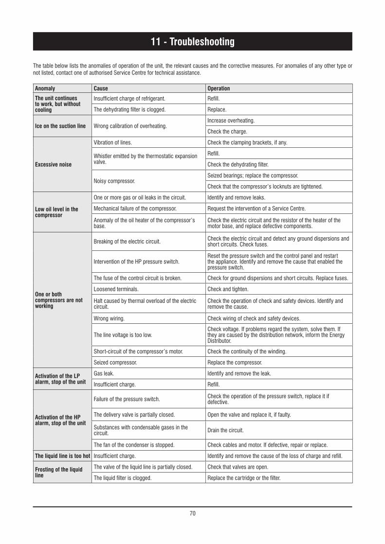
70
11 - Troubleshooting
The table below lists the anomalies of operation of the unit, the relevant causes and the corrective measures. For anomalies of any other type or not listed, contact one of authorised Service Centre for technical assistance.
Anomaly Cause Operation
The unit continues to work, but without cooling
Insufficient charge of refrigerant. Refill.
The dehydrating filter is clogged. Replace.
Ice on the suction line Wrong calibration of overheating.Increase overheating.
Check the charge.
Excessive noise
Vibration of lines. Check the clamping brackets, if any.
Whistler emitted by the thermostatic expansion valve.
Refill.
Check the dehydrating filter.
Noisy compressor.Seized bearings; replace the compressor.
Check that the compressor’s locknuts are tightened.
Low oil level in the compressor
One or more gas or oil leaks in the circuit. Identify and remove leaks.
Mechanical failure of the compressor. Request the intervention of a Service Centre.
Anomaly of the oil heater of the compressor’s base.
Check the electric circuit and the resistor of the heater of the motor base, and replace defective components.
One or both compressors are not working
Breaking of the electric circuit. Check the electric circuit and detect any ground dispersions and short circuits. Check fuses.
Intervention of the HP pressure switch.Reset the pressure switch and the control panel and restart the appliance. Identify and remove the cause that enabled the pressure switch.
The fuse of the control circuit is broken. Check for ground dispersions and short circuits. Replace fuses.
Loosened terminals. Check and tighten.
Halt caused by thermal overload of the electric circuit.
Check the operation of check and safety devices. Identify and remove the cause.
Wrong wiring. Check wiring of check and safety devices.
The line voltage is too low.Check voltage. If problems regard the system, solve them. If they are caused by the distribution network, inform the Energy Distributor.
Short-circuit of the compressor’s motor. Check the continuity of the winding.
Seized compressor. Replace the compressor.
Activation of the LP alarm, stop of the unit
Gas leak. Identify and remove the leak.
Insufficient charge. Refill.
Activation of the HP alarm, stop of the unit
Failure of the pressure switch. Check the operation of the pressure switch, replace it if defective.
The delivery valve is partially closed. Open the valve and replace it, if faulty.
Substances with condensable gases in the circuit. Drain the circuit.
The fan of the condenser is stopped. Check cables and motor. If defective, repair or replace.
The liquid line is too hot Insufficient charge. Identify and remove the cause of the loss of charge and refill.
Frosting of the liquid line
The valve of the liquid line is partially closed. Check that valves are open.
The liquid filter is clogged. Replace the cartridge or the filter.

71
Engl
ish
12.1 Spare part list
The table below shows the list of spare parts recommended during the first two years of operation.
12.2 Oil for compressors
The compressors are lubricated with polyester oil (P.O.E.).
12.3 Wiring diagrams
The wiring diagrams are installed inside the doors of the electrical panels of the unit. Any request for wiring diagrams shall be forwarded to manufacturer’s Service Centre.
Component NumberFan 1
High pressure switch 2
Differential water pressure switch 1
High pressure transducer 2
Low pressure transducer 2
Expansion valve 1
Gas filter 1
Four-way valve 1
Electronic main board 1
Auxiliary main board transformer 1
Auxiliary circuit transformer 1
Compressor contactor 2
Pump contactor 1
Water sensor 4
Air sensor 1
Automatic switch compressor protection 2
Automatic switch pump protection 1
Auxiliary contact 4
Fan capacitor 1
Auxiliary switch 1
Fuses 4
12 - Spare Parts
72
13 - Dismantling, Demolition and Scrapping
DANGER
During the draining of the refrigeration circuits, do not let the refrigerant overflow in the surrounding atmosphere.
The circuit must be drained using suitable recovery equipment.
DANGER
Do not disperse the waste oil of the compressors in the environment, since it contains some dissolved refrigerant.
For the disposal, contact the competent authority for information.
Unless otherwise specified, the maintenance operations listed below may be carried out by any trained maintenance operator.
13.1 Generalities
Open each line that supplies the unit, including the ones of control circuits. Make sure that all disconnecting switches are secured in the off position. The power cables can be disconnected and disassembled. Refer to Chapter 4 for the position of connection points.
Remove all the refrigerant from the refrigeration circuits of the unit and store it in suitable containers, using a recovery unit. If its characteristics have remained the same, the refrigerant can be used again. Contact the competent authority to obtain information about disposal. In NO event shall the refrigerant be discharged into the atmosphere. The oil in each refrigeration circuit must be drained and collected into a suitable container; then it shall be disposes of in conformity with local regulations that apply to the disposal of waste lubricants. Any oil spillage must be recovered and disposed of in like manner.
Isolate the unit’s heat exchangers from the external hydraulic circuits and drain the heat exchange sections of the plant.
DANGER
If no shutoff valves have been provided, it may be necessary to drain the whole plant.
If a glycoled solution or a similar fluid has been used in the hydraulic circuits, or if chemical additives have been added to the circulating water, the circulating fluid MUST be drained in a proper way.
For NO reason shall a circuit containing glycoled water or a similar solution be discharged directly into the drains or surface waters.
After draining operations, the piping of the hydraulic networks can be disconnected and disassembled.
Once they have been disconnected as specified, the packaged units can be disassembled in a single piece. First of all, disassemble the anchoring screws and then lift the unit from the position of installation, and hook it to the lifting points provided, using suitable lifting equipment.
To this end, refer to Chapter 4 for the installation of these appliances, to Chapter 9 for their weights and Chapter 3 for handling.
The units that, once disconnected, cannot be removed in a single piece, must be dismantled on site; in this case, be very careful with the weight and handling of every single component.
It is always advisable to dismantle the units following the installation steps, but in reverse.
DANGER
Some residues of oil, glycoled water or similar solutions may remain in certain parts of the unit. These residues must be recovered and disposed of according to the procedures specified above.
It is very important to ensure that, while a component of the unit is being removed, all the others are properly supported.
DANGER
Use only lifting means of adequate capacity.
Once disassembled, the components of the unit can be disposed of in conformity with current regulations.

III

As part of our ongoing product improvement programme, our products are subject to change without prior notice. Non contractual photos.Dans un souci d’amélioration constante, nos produits peuvent être modifiés sans préavis. Photos non contractuelles.In dem Bemühen um ständige Verbesserung können unsere Erzeugnisse ohne vorherige Ankündigung geändert werden. Fotos nicht vertraglich bindend.A causa della politica di continua miglioria posta in atto dal costruttore, questi prodotti sono soggetti a modifiche senza alcun obbligo di preavviso. Le foto pubblicate non danno luogo ad alcun vincolo contrattuale.Con objeto de mejorar constantemente, nuestros productos pueden ser modificados sin previo aviso. Fotos no contractuales.
AIRWELL ItALIAVia XXV Aprile, 2920030 Barlassina (MI)Italy& : +39 0362 680.16 : +39 0392 680.281