Embed Size (px)
Citation preview
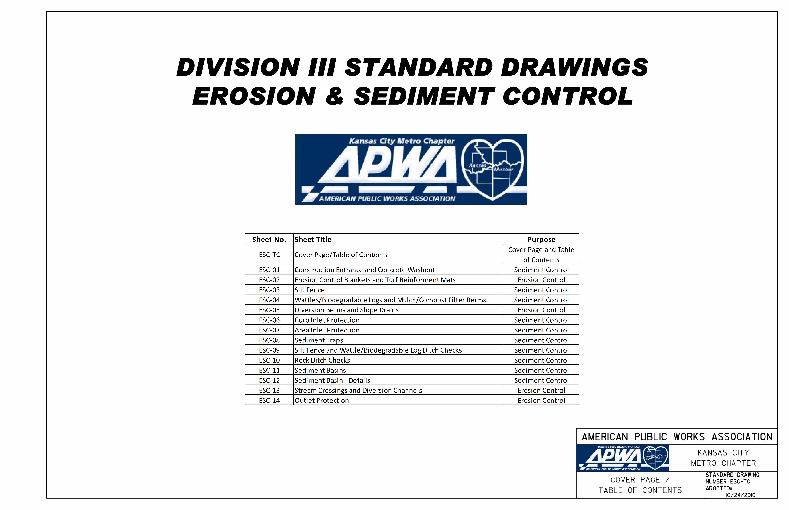
EROSION & SEDIMENT CONTROL
DIVISION III STANDARD DRAWINGS
NUMBER ESC-TC
TABLE OF CONTENTS
COVER PAGE /STANDARD DRAWING
ADOPTED:
AMERICAN PUBLIC WORKS ASSOCIATION
METRO CHAPTER
KANSAS CITY
10/24/2016
Existing Ground
Non-Woven Geotextile
5:1
Existing Pavement
Mountable Berm (Optional)
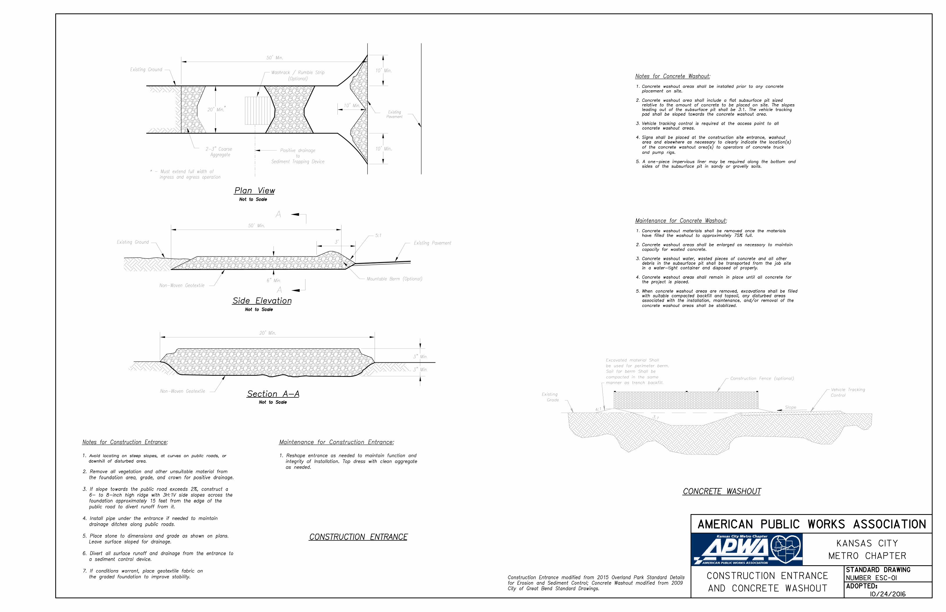
Side ElevationNot to Scale
CONSTRUCTION ENTRANCE
50' Min.
6" Min.
A
A
10' Min.
10' Min.
Pavement
Existing
10' Min.20' Min.
(Optional)
Washrack / Rumble Strip
50' Min.
Existing Ground
Sediment Trapping Device
to
Positive drainage
ingress and egress operation
* - Must extend full width of
Aggregate
2-3" Coarse
20' Min.
Non-Woven Geotextile
3" Min.
3" Min.
Plan ViewNot to Scale
Section A-ANot to Scale
3'
CONCRETE WASHOUT
sides of the subsurface pit in sandy or gravelly soils.
5. A one-piece impervious liner may be required along the bottom and
and pump rigs.
of the concrete washout area(s) to operators of concrete truck
area and elsewhere as necessary to clearly indicate the location(s)
Signs shall be placed at the construction site entrance, washout4.
concrete washout areas.
Vehicle tracking control is required at the access point to all3.
pad shall be sloped towards the concrete washout area.
leading out of the subsurface pit shall be 3:1. The vehicle tracking
relative to the amount of concrete to be placed on site. The slopes
Concrete washout area shall include a flat subsurface pit sized2.
placement on site.
Concrete washout areas shall be installed prior to any concrete1.
Excavated material Shall
be used for perimeter berm.
Soil for berm Shall be
compacted in the same
manner as trench backfill.
Existing
Grade
Construction Fence (optional)
Vehicle Tracking
Control
Slope
3:1
4:1
City of Great Bend Standard Drawings.
for Erosion and Sediment Control; Concrete Washout modified from 2009
Construction Entrance modified from 2015 Overland Park Standard Details
*
the graded foundation to improve stability.
7. If conditions warrant, place geotextile fabric on
a sediment control device.
6. Divert all surface runoff and drainage from the entrance to
Leave surface sloped for drainage.
5. Place stone to dimensions and grade as shown on plans.
drainage ditches along public roads.
4. Install pipe under the entrance if needed to maintain
public road to divert runoff from it.
foundation approximately 15 feet from the edge of the
6- to 8-inch high ridge with 3H:1V side slopes across the
3. If slope towards the public road exceeds 2%, construct a
the foundation area, grade, and crown for positive drainage.
2. Remove all vegetation and other unsuitable material from
downhill of disturbed area.
Avoid locating on steep slopes, at curves on public roads, or1.
Notes for Construction Entrance: Maintenance for Construction Entrance:
1. Reshape entrance as needed to maintain function and
integrity of Installation. Top dress with clean aggregate
as needed.
Notes for Concrete Washout:
Maintenance for Concrete Washout:
concrete washout areas shall be stabilized.
associated with the installation, maintenance, and/or removal of the
with suitable compacted backfill and topsoil, any disturbed areas
When concrete washout areas are removed, excavations shall be filled5.
the project is placed.
Concrete washout areas shall remain in place until all concrete for4.
in a water-tight container and disposed of properly.
debris in the subsurface pit shall be transported from the job site
Concrete washout water, wasted pieces of concrete and all other3.
capacity for wasted concrete.
Concrete washout areas shall be enlarged as necessary to maintain2.
have filled the washout to approximately 75% full.
Concrete washout materials shall be removed once the materials1.
NUMBER ESC-01
AND CONCRETE WASHOUT
CONSTRUCTION ENTRANCESTANDARD DRAWING
ADOPTED:
AMERICAN PUBLIC WORKS ASSOCIATION
METRO CHAPTER
KANSAS CITY
10/24/2016

8" Mi
n.
blank
et o
verla
p
4" o
n ce
nter
Slope
6" Min.
6"
Min.
Varies
Limits of Erosion
Control Blanket
Not to Scale
15' Min.
*
(where directed by the plans)
permanent slope protection
is immediately covered by
may be omitted if the area
Erosion Control Blanket or TRM - *
12" Min.
Flow
6" Min.
6"
Min.
Flow
Slope
6"
Min.
A
B
C
A
B
C
- Overlaps and seams;
- Projected water line;
- Channel bottom / side slope vertices;A
B
C
Installation Around Culvert Slope
Installation on Slopes
Splice Seam
Splice Seam
Longitudinal Seam Anchor FoldAnchor SlotLongitudinal Seam
Edge Anchor
V Channel
Trapezoidal Channel
Critical Points:
Partial Box Culvert Plan
Installation in Channels
with anchors 9 inches apart.
turned under a minimum of 4 inches, then anchored in place
4. TERMINAL FOLD: The bottom edge of the blanket shall be
seams.
minimum of 8 inches in direction of water flow. Stagger splice
3. SPLICE SEAM: When splices are necessary, overlap end a
then backfilled, tamped and seeded.
deep with the blanket anchored in the bottom of the slot,
inches apart. The slots should be 6 inches wide x 6 inches
at the top of the slope and anchored in place with anchors 6
2. ANCHOR SLOTS: The top of the blanket should be "slotted in"
with the soil, lay blanket loosely, avoiding stretching.
direction of the slope. In order for blanket to be in contact
1. Erosion Control Blankets and TRMs shall be laid in the
Notes for Installation on Slopes:
catching the edges of both blankets.
overlap each other a minimum of 6 inches, with anchors
LONGITUDINAL SEAMS: The edges of the blanket or mat should3.
to the manufacturers instructions.
Typical anchors and pattern/spacing shall be installed according2.
referenced to select type of blanket or mat to be used.
APWA Specifications 2150 and Design Guidance 5100 shall be1.
6. TERMINUS: The bottom edge of the mat shall be anchored.
of the slope and anchor.
5. EDGE ANCHORS: Lay outside edge of mat into trench at top
shall then cover the slot and be anchored as shown.
and buried similar to the edge anchor fold. The upstream mat
The top of the downstream mat shall be slotted in, secured
The mat shall be cut to a length 12 inches beyond the slot.
30 feet. The slots should be 6 inches wide x 6 inches deep.
4. CHECK SLOTS: Establish check slots transverse to slope every
splice seams.
minimum of 12 inches in direction of water flow. Stagger
3. SPLICE SEAM: When splices are necessary, overlap end a
the top as shown in detail.
the bottom of the slot, backfilled, and the mat folded over
buried in a slot 6 inches wide x 6 inches deep, anchored in
placed 6 inches apart. The top edge of the mat should be
buried and secured with wood or other approved anchors
2. ANCHOR FOLD: The top of the mat should be folded under,
contact with the soil, lay the mat loosely, avoiding stretching.
of channel, where applicable. In order for the mat to be in
direction of the flow, with the first course at the centerline
1. Erosion Control Blankets and TRMs shall be laid in the
Notes for Installation in Channels:
for Erosion and Sediment Control.
Modified from 2015 Overland Park Standard Details
General Notes:
Maintenance:
1. Torn or degraded product shall be repaired or replaced, unless
such degradation is within the functional longevity specified by
the manufacturer.
2. Edges or seams that are loose or frayed shall be secured.
NUMBER ESC-02
AND TURF REINFORMENT MATS
EROSION CONTROL BLANKETSSTANDARD DRAWING
ADOPTED:
AMERICAN PUBLIC WORKS ASSOCIATION
METRO CHAPTER
KANSAS CITY
10/24/2016

Backfilled trench
2' Min.
Direction of Flow
FLOW
POSTS(*)
SILT FENCE DETAILS
Not to Scale
at 4' max spacing
4' min length post
(See Note 6.)
Post embedment
2' Min.
Tire compaction zone
3' wide
Geotextile fabric
fastened to the post.
spacing of 6" which has been
between 9 and 14 and max. mesh
wire fencing with min. wire gauge
material can be attached to woven
For additional strength filter fabric
Posts (*) at 4' Max. spacing
- STEEL 1.33 LB/FT
"85" x 2 8
5- NO.2 SOUTHERN PINE 2
"163" x 1 16
3- HARDWOOD 1
- MIN, LENGTH 4'
Material (**)
Filter fabric
of AASHTO M288
meet the requirements
(**) - Geotextile Fabric shall
(50 lb tensile strength) located in top 8"
approved by the field engineer,
Staples, plastic zip ties or other material
6" - 12" depth
Machine slice
Figure A
Incorrect
980
978
976
982
980
978
982
Flo
w
Street
Street
Street
Street
100' Maximum Runs (Typ.)
Silt Fence
Uphill (Typ)
Ends Turned
SILT FENCE LAYOUT
Not to Scale
6' - 10'
Flo
w
sediment storage area.
6' to 10' away from the toe to create a
to slow velocity and volume of water and
nstall silt fence at the top of the slope I
976
Flow
Correct
Silt fence post
Overlap filter fabric between posts
JOINING FENCE SECTIONS
staples or plastic zip ties
attach to the post with
Wrap filter fabric around and
Not to Scale
Silt Fence
18" Minimum
used.
installation, where slicing machine cannot be reasonably
6. Trenching will only be allowed for small or difficult
5. Install posts a minimum of 2' into the ground.
4. Attach fabric to upstream side of post.
of silt fence to slow runoff velocities.
3. Long slopes should be broken up with intermediate rows
(Figure A).
smaller segments to minimize water concentrations
limited to 100'. Runs should be broken up into several
2. Long perimeter runs of silt fence must be
fence must be turned uphill (Figure A).
1. In order to contain water, the ends of the silt
Notes:
for Erosion and Sediment Control.
Modified from 2015 Overland Park Standard Details
Maintenance:
1. Remove and dispose of sediment deposits when the deposit
approaches 13 the height of silt fence.
2. Repair as necessary to maintain function and structure.
NUMBER ESC-03SILT FENCE
STANDARD DRAWING
ADOPTED:
AMERICAN PUBLIC WORKS ASSOCIATION
METRO CHAPTER
KANSAS CITY
10/24/2016

Berm
Berm
Figure 1 Figure 2
WATTLES AND BIODEGRADABLE LOG
Section A-A Typical Elevation
maximum length of 10".
Mulch sizing varies with a maximum width of 2" and a
tub grinder or other approved method.
by the mechanical means such as a chipper, hammermill,
resulting from clearing and grubbing and shall be ground
5. Wood mulch shall consist of tree and shrub debris
runoff channels or concentrated flow areas.
4. Do not use compost or wood mulch berms in any
during application for permanent vegetation.
natural landscape, the compost berm may be seeded
3. If berm is to be left as permanent or part of the
slope. Engineer will specify berm requirements.
a second berm shall be constructed at the top of the
In extreme conditions, or where specified by the engineer,
a minimum of 4 feet wide at the base (see Figure 2).
construct a 1.5 to 3 foot high trapezoidal berm that is
For maximum water treatment ability or for steep slopes,
foot high by 2.5 to 3 foot wide berm (see Figure 1).
perimeter of other affected areas, construct a 1 to 3
2. Parallel to the base of the slope, or around the
directed by the engineer.
in a windrow at locations shown on the plans or as
1. The sediment control berm shall be placed uncompacted
:Notes for Mulch and Compost Filter Beam
MULCH OR COMPOST FILTER BERMS
:Protection
Notes for Wattles and Biodegradable Log Slope
4.0'
1.5' - 3.0'
Maintenance for Mulch and Compost Filter Beam:
1. Berm shall be reshaped and material added as necessary
to maintain function and dimensions.
2. Breaches in the berm shall be repaired promptly.
for Erosion and Sediment Control.
Modified from 2015 Overland Park Standard Details
of the log with minimum of 24".
Length of stakes shall be a minimum of 2 times the diameter
Spacing of stakes per manufacturer's instructions with 4' max. spacing.3.
Install wattles and biodegradable logs per manufacturer's instructions.2.
and the barrier ends need to be staggered.
maximum length of the slope barrier shall not exceed 250 feet,
short section turned upgrade at each end of the barrier. The
The Slope barriers shall be placed along contour lines, with a1.
NUMBER ESC-04
A
A
Stakes (typ.)
Direction of Flow
4' ( max. )
MULCH/COMPOST FILTER BERM
AND
WATTLES/BIODEGRADABLE LOG
Wattle or Biodegradable Log
2.5' - 3.0'
(Perimeter Control) (Steep Slopes)
Trenching per manufactures instructions.1.0' - 3.0'
STANDARD DRAWING
ADOPTED:
AMERICAN PUBLIC WORKS ASSOCIATION
METRO CHAPTER
KANSAS CITY
10/24/2016

Diversion Berm
and
direct runoff to slo
pe drain
Length as required to cantain
Top of Slope
Toe of Slope
Slope
approved material
Rock Dissipator or other
A
A
B
B
24' Min.
18" Min.
2:1 Slope or flatter
2:1 Slope or flatter
Existing Ground
Flow
flow width and flow depth
Grade to provide required
b
a
b - Flow Depth = 70% Max. of berm height.
a - Flow Width = 4' Min.
Not to Scale
earthwork operations progress
to match height of slope as
Adjust length of Slope Drain
Diversion Berm
6" Metal, Plastic or Flexible Rubber Pipe
approved material
Rock Dissipator or other Varies
2' Min.
4'
6"
1'
Diversion Berm
Surface of Compacted Fill
Face of Slope
2:1 Max.
Section C-C
1'
2:1 Max.2:1 Max
.
2' Min.
Section B-B
C
C
Slope Drain
AND SLOPE DRAIN
TYPICAL PLAN VIEW OF DIVERSION BERM
materials.
excessive organic debris, rocks or other objectionable
diversion. Fill shall be composed of soil which is free from
settlement that would cause damage in the completed
9. Fills shall be compacted as needed to prevent unequal
free of irregularities which will impede flow.
cross-section as required to meet the criteria specified herein,
8. The diversion shall be excavated or shaped to line, grade and
interfere with the proper functioning of diversion.
material shall be removed and disposed of so as not to
7. All trees, brush, stumps, obstructions and other objectionable
stabilized area.
6. The berm must discharge to a temporary sediment trap or
operations and traffic.
5. Place the berm so to minimize damages by construction
to the berm immediately following its construction.
4. Temporary or permanent seeding and mulch shall be applied
3. The berm should be adequately compacted to prevent failure.
upslope land disturbance.
in the land-disturbing activity and must be functional prior to
Diversion berms must be installed as a first step2.
if the berm is at the top of a steep slope.
1. Slope drains are optional, but may be required by the engineer
3. Pipe shall be secured in place as approved by Engineer.
area, or into Sediment Basin.
2. Discharge of Slope Drains shall be into stabilized ditch or
on either project foreslopes or project backslopes.
1. Slope Drain and Diversion Berm may be used
:Notes for Slope Drain
Slope Drain Pipe2:1
Max.
Transverse Berm
Transverse Berm
Min.
Min.
Min.
Berm (Tra
nsverse)
Notes for Diversion Berm:
for Erosion and Sediment Control.
Modified from 2015 Overland Park Standard Details
TYPICAL PROFILE OF DIVERSION BEAM
Maintenance:
1. Accumulation of any visible sediment at the inlet and
outlet shall be removed promptly.
2. Outlet conditions shall be repaired if scour is observed.
Leaking or damaged section of pipe shall be repaired
immediately.
3. Barriers directing water to the inlet shall be monitored for
continuity and effectiveness.
Maintenance:
1. Berm shall be reshaped, compacted, and stabilized as
necessary to maintain its function.
2. Breaches in the berm shall be repaired immediately.
TYPICAL PROFILE OF DIVERSION BERM WITH SLOPE DRAIN
TYPICAL PROFILE OF DIVERSION BERM
NUMBER ESC-05
SLOPE DRAINS
DIVERSION BERMS ANDSTANDARD DRAWING
ADOPTED:
AMERICAN PUBLIC WORKS ASSOCIATION
METRO CHAPTER
KANSAS CITY
10/24/2016

Front View
Or turfPavement
Top of inlet
4" - 6"
10' Typ.
On Grade Curb Inlet Protection
at approximately 10' interval
along curb as needed
Filter socks to be placed
Sediment
Flow
Board
2" x 10" (min).
board & staple
around 2"X10" (min.)
Wrap silt fence
1" dia.
" to 21Gravel
Sump Inlet Sediment Filter
inlet.
not be above the top of the
Height of filter sock should
beyond inlet opening.
and extend approximately 6"
curb contact with no gaps
Filter sock is to have a tight
." to 1" Dia21
Gravel
unintended flooding.
Ponded Water Depth will not cause
* Contractor shall field verify that
Existing Ground
on all four sides.
Excavated area surrounding inlet
See Detail A below
Detail A
Proposed finished grade
24" Max.
10" Min.
Weep Hole
in silt fence.
Board wraped
A
A
A - A
of inlet.
the front and sides
Place gravel along
Top View
Curb & Gutter
Curb & Gutter
traffic hazard.
3. Contractor to field verify ponding water shall not create a
Straw wattles are not approved for curb inlet use.
or approved equal should be used (Late Stage Curb Inlet).
2. When inlet is completed and curb poured, filter socks
sides to allow settling of sediment (Early Stage Curb Inlet).
Structures shall have excavated storage area on all four
by installing 2" X 10" (min.) board wrapped in silt fence.
construction of curb and inlet throat, protect inlet opening
1. Immediately following inlet construction and prior to
Notes:
Curb and Inlet Throat)
(Open Box and Prior to Pouring
EARLY STAGE CURB INLET
LATE STAGE CURB INLET
Curb Line
for Erosion and Sediment Control.
Modified from 2015 Overland Park Standard Details
(After Pouring Curb and Inlet Throat)
Maintenance:
1. Remove deposited sediment from excavated storage areas when available storage has
been reduced by 20%.
2. Remove deposited sediment from filter socks or similar when any accumulation of
sediment is visible.
3. Repair or replace as necessary to maintain function and integrity
of installation.
NUMBER ESC-06CURB INLET PROTECTION
STANDARD DRAWING
ADOPTED:
AMERICAN PUBLIC WORKS ASSOCIATION
METRO CHAPTER
KANSAS CITY
10/24/2016

." to 1" Dia21
GravelFinished Grade
Proposed
Swale Flow
2' Min.
Excavation
Limits of
of Swale
Centerline
Sediment Storage
Excavated Area for
A
Depth (*)
Ponded Water
will not cause excessive unintended flooding.
* - Contractor shall field verify that Ponded Water DepthExisting Ground
A
Not to Scale
Not to Scale
Section A-A
Plan
4' Max.
S
TORM SEW
ER
IC TY
Front View
Top of inlet
Final stabilized grade
Swale Flo
w
." to 1" Dia21
Gravel
approved Erosion Control Product
consisting of vegetation or
Stabilized Buffer10'
(Typical all sides)
Not to Scale
Plan
(All open boxes and inlets not at final grade)
EARLY STAGE AREA INLET
silt fence attached to wood frame.
Wire reinforced silt fence may be used in place of4.
immediately follow.
of the site. Stabilization of the site is to
Backfill excavated area ONLY after final grading3.
is removed and Late Stage Area Inlet is being installed.
Silt fence shall remain in place until excavated area2.
constructed.
immediately after inlet or junction box is
Early Stage Area Inlet Sediment Barrier to be installed1.
Notes:
(Area inlets at final grade and existing inlets)
LATE STAGE AREA INLET
(Not to be placed in throat of inlet).
in front of each inlet opening.
other approved sediment control device
Place biodegradable log, staked wattles or
24" max
10" min
Wire Reinforced Silt Fence
for Erosion and Sediment Control.
Modified from 2015 Overland Park Standard Details
Installation Requirements)
(See Silt Fence Detail for
Wire Reinforced Silt Fence
prevent bypass
of downstream berm to
Top of silt fence below top
Maintenance:
1. Remove deposited sediment from excavated storage areas when
available storage has been reduced by 20%.
2. Remove deposited sediment from filter socks or similar when any
accumulation of sediment is visible.
3. Repair or replace as necessary to maintain function and integrity
of installation.
NUMBER ESC-07
JUNCTION BOX PROTECTION
AREA INLET ANDSTANDARD DRAWING
ADOPTED:
AMERICAN PUBLIC WORKS ASSOCIATION
METRO CHAPTER
KANSAS CITY
10/24/2016

1' W
2 :
1
elevation
Original ground
Storage Capacity:
67 Cu. Yd. per Acre
of drainage area
4'
Max.
2 :
1
Aggregate
2" Coarse 10" Riprap
(Optional)
Geotextile
elevation
Original ground
Length in Feet = 6 x Drainage Area in AC.
Diversion Dike
10" Riprap
2" Coarse Aggregate
(Optional)
Geotextile
Excavated Area
Not to Scale
Not to Scale
(*) Cross Section of Outlet
(*) Perspective View of Outlet
construction arrangements.
Construction plans must provide specific site
schematic in nature.
*) - The perspective view and cross section are(
H
Ho
1.5
2.0
2.5
3.0
3.5
4.0
4.5
5.0
0.5
1.0
1.5
2.0
2.5
3.0
3.5
4.0
2.0
2.0
2.5
2.5
3.0
3.0
4.0
4.5
H H WO
1' 2'
2 :
12 :
1
3'
Pipe Invert
Sediment
Stor
age Are
a
Flow
Flo
w
Flow
Flo
w
(24" Min.)
Stabilize
Flow
Areas to be disturbed
Pipe Invert
storage area
at 20% volume of wet
Max. sediment depth
Coarse Aggregate d = 2"
d 10" Stone
berm and pipe
between
Stabilize area
50
50 Riprap Headwall
Natural Ground
Not to Scale
Plan View
Not to Scale
Section A-A
AA
d 10" Stone50
Coarse Aggregate d = 2"50
Dike
Top of Diversion
1' Min.
elevation
Original ground
24" Min.
maximum 1H : 1V grade.
for excavated, wet storage areas which may be at a
6. All cut and fill slopes shall be 2H : 1V or flatter, except
the upslope drainage area has been stabilized.
5. The structure shall be removed and the area stabilized when
erosion and water pollution.
4. Construction operations shall be carried out to minimize
after installation.
3. The earthen embankment shall be stabilized immediately
equipment.
compacted in 6-inch layers by traversing with construction
other objectionable material. The embankment should be
other woody vegetation, organic material, large stones, and
2. Fill material for the embankment shall be free of roots or
and stripped of any vegetation and root mat.
1. The area under the embankment shall be cleared, grubbed,
Notes for Sediment Trap:
stone berm.
7. 67 C.Y./Acre dry storage from base of stone to top of
6. 67 C.Y./Acre wet storage below base of stone.
sediment trap.
5. Storage requirements equivalent to that of temporary
outlet for flows from larger storm events.
the culvert opening to provide an acceptable emergency
4. The toe of the riprap shall be no closer than 24" from
the culvert inlet.
3. Geometry of the design will be a horseshoe shape around
areas or structures.
cause excessive inconvenience or damage to adjacent
manner that any resultant ponding stormwater will not
2. The inlet protection devices shall be constructed in such
construction activities.
trapped sediment and minimize interference with
manner that will facilitate clean-out and disposal of
1. The inlet protection device shall be constructed in a
Notes for Sediment Trap at Culvert Opening:
SEDIMENT TRAP SEDIMENT TRAP AT CULVERT OPENING
for Erosion and Sediment Control.
Modified from 2015 Overland Park Standard Details
Maintenance for Sediment Trap:
1. Check sediment traps after periods of significant runoff.
2. Remove sediment and restore the trap to its original dimensions when
sediment accumulates to 20% of the storage capacity.
3. Immediately repair any erosion damage to the embankment and outlet.
4. Keep outlet and pool area free of all trash and other debris.
Maintenance for Sediment Trap at Culvert Opening:
NUMBER ESC-08SEDIMENT TRAPS
STANDARD DRAWING
ADOPTED:
AMERICAN PUBLIC WORKS ASSOCIATION
METRO CHAPTER
KANSAS CITY
10/24/2016

SILT FENCE DITCH CHECK
Slope ( % )
Ditch Centerline
(Feet)
Spacing Interval
1.0 200
2.0 100
3.0 65
4.0 50
5.0 40
6.0 33
except Rock Ditch Checks.
Note: Use this spacing for all
Ditch Check Spacing
Alternative Type
Details for Erosion Control and Sediment Control.
Modified from Kansas Department of Transportation Standard
WATTLES OR BIODEGRADABLE LOG DITCH CHECKS
NUMBER ESC-09
6:1 or varies4:1 o
r varies
Standard or Special DitchShoulder Typical Foreslope Typical Backslope
TYPICAL ELEVATION
Flowline of Ditch
4' max. (typ.) 4' max. (typ.) 4' max. (typ.)
4'' (ty
p.)
Silt Fence Fabric
B
B
SECTION B-B
of FlowDirection
3' wide
Geotextile fabric
Tire compaction zone
6" - 12" depth
Machine slice
post embedment
2' min.
4' max. spacing
4' min. length post at
in top 8".
(50 lb. tensile strength) located
approved by the field engineer
Plastic zip ties, or other material
Stakes shall be set at an 2' minimum depth
Silt Fence Fabric
Stake
6''
6''
(50 lb. tensile strength) located in top 8".
approved by the field engineer,
Plastic zip ties, or other material
NO SCALE
SECTION B - B
OR Filter Sock Ditch Check
NO SCALE
PLAN
Direction of Flow
B
B
Staples (typ.)
Stakes (typ.)
4' ( max. )
4' ( max. )4'' ( min. )
(Optional)
Downstream Apron
TYPICAL ELEVATION
Notes for Silt Fence Ditch Check:
1. Stakes shall be 4' (min.) long and one of
the following materials:
";163" x 1 16
3 a. Hardwood - 1
";85" x 2 8
5 b. Southern Pine (No. 2) - 2
c. Steel U, T, L, or C Section - .95 lbs. per 1'-0";
d. Synthetic - same strength as wood stakes.
2. Cross pieces shall be of same material as stakes.
3. Attach fence fabric securely on 6" centers (max.).
4. Use of high flow material is acceptable.
5. Refer to plan sheets to estimate the length of silt
fence required.
6. Use support fencing when tributary area is greater
than 2.4 acres or when ditch gradient is greater
than 2 percent.
in Anchor Trench.
Soil or Gravel Backfill
of Flow
Direction
(min.) @ 3' o/c
6'' long x 1'' wide
Wire Staples:
finish grade (typ.)
of stake 12'' above
Set end stakes with top
slicing depth
6" minimum
(typ. each side)
Fabric to fit slopes.
Fold Silt Fence
Trench.
Backfill in Anchor
Soil or Gravel
(typ.)
2'
Direction of Flow
Wattle or Biodegradable Log
Trenching per manufactures instructions.
Notes for Wattles and Biodegradable Log Ditch Check:
DITCH CHECKS
BIODEGRADABLE LOG
SILT FENCE AND WATTLE/
directed by the Engineer.
Control (Class 2) (Any Type) channel lining as
Smaller diameter logs may be used with Erosion
Control (Class 2) (Any Type) channel lining.
Use 9" diameter logs when used with Erosion 5.
downstream apron when directed by the Engineer.
Use Erosion Control (Class 1) (Type C) as the 4.
the diameter of the log or 24" minimum.
Length of stakes shall be a minimum of 2 times
Stakes shall be per manufacturer's instructions.3.
Overlap sections a minimum of 18"2.
end of ditch check.
necessary to ensure water does not flow around
Use as many biodegradable log sections as 1.
7. Silt fence sliced in to a 6" minimum depth.
8. Elevation at tie in points shall be a minimum of
4" higher than the center.
STANDARD DRAWING
ADOPTED:
AMERICAN PUBLIC WORKS ASSOCIATION
METRO CHAPTER
KANSAS CITY
10/24/2016
FLOW
B
A A
B
Spacing Between Check Dams (all types)
Front View
FLOW
FLOW
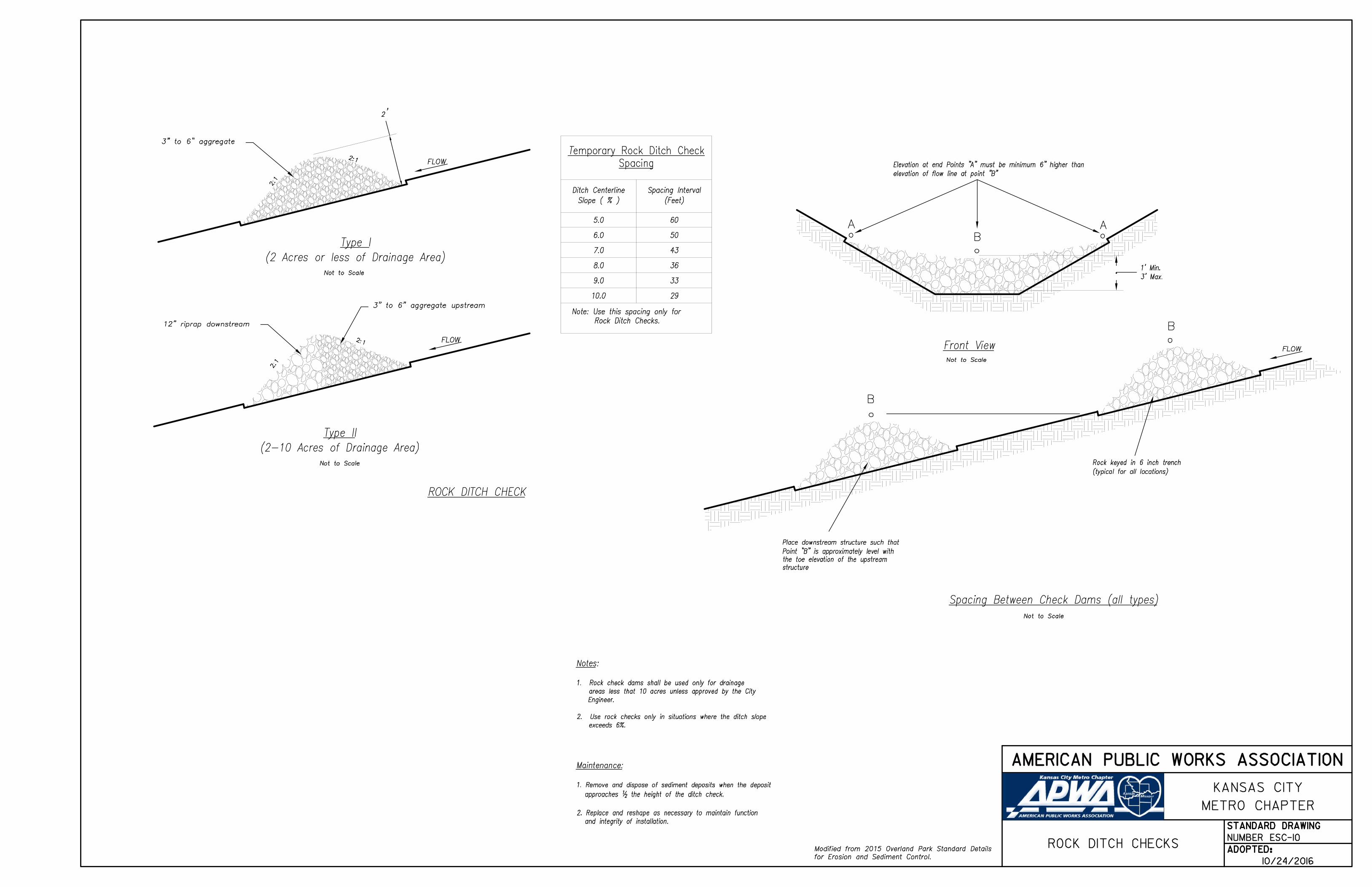
3" to 6" aggregate
12" riprap downstream B
2:1
2:1
2:1
2:1
structure
the toe elevation of the upstream
Point "B" is approximately level with
Place downstream structure such that
3' Max.
1' Min.
3" to 6" aggregate upstream
elevation of flow line at point "B"
Elevation at end Points "A" must be minimum 6" higher than
(typical for all locations)
Rock keyed in 6 inch trench
Not to Scale
Not to Scale
Not to Scale
Not to Scale
(2 Acres or less of Drainage Area)
Type I
(2-10 Acres of Drainage Area)
Type II
ROCK DITCH CHECK
'2
Spacing
emporary Rock Ditch Check T
Slope ( % )
Ditch Centerline
(Feet)
Spacing Interval
5.0 60
6.0 50
7.0 43
8.0 36
9.0 33
10.0 29
Rock Ditch Checks.
Note: Use this spacing only for
Notes:
1. Rock check dams shall be used only for drainage
areas less that 10 acres unless approved by the City
Engineer.
2. Use rock checks only in situations where the ditch slope
exceeds 6%.
for Erosion and Sediment Control.
Modified from 2015 Overland Park Standard Details
Maintenance:
1. Remove and dispose of sediment deposits when the deposit
approaches 12 the height of the ditch check.
2. Replace and reshape as necessary to maintain function
and integrity of installation.
NUMBER ESC-10ROCK DITCH CHECKS
STANDARD DRAWING
ADOPTED:
AMERICAN PUBLIC WORKS ASSOCIATION
METRO CHAPTER
KANSAS CITY
10/24/2016
15' max.
8' min.
Engineer to prevent floatation
Concrete block - sized by Anti-seep collars
Min. 2
conduit
Principal spillway
outlet
Stabilized
Trash rack(134 CY/Acre min.)
Sediment Storage
Settlement Zone and
Stormwater storage
(Spillway designed to pass 4% storm)
Min. Elevation of Emergency spillway.
basin
following the construction of
vegatation immediately
Embankment stabilized with
3:1 max.
fill
Compacted
3:1
max.
max.
3 : 1
Baffles
1' min.
Freeboard
1' min.
design Elevation
4% storm
(not to overtop emergency spillway)
50% storm design Elevation
INFL
OW
INFLO
W
min. length flat section
control section- 20 ft.
Emergency spillway
constructed over fill material
Emergency spillway should not be
(extend to edge of disturbance)
withstand 4% design storm flow
Channel lining material to
event of blockage)
(located for accessibility in
Primary Spillway w/skimmer
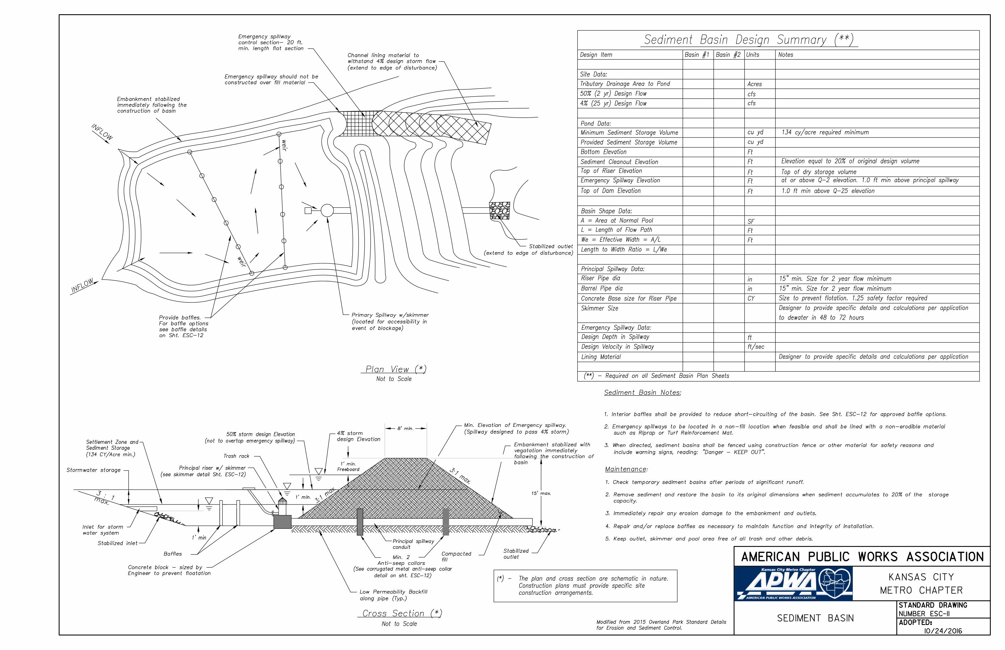
Plan View (*)
Cross Section (*)
Not to Scale
Not to Scale
water system
Inlet for storm
1' min
Sediment Basin Design Summary (**)
Design Item Basin #1 Basin #2 Units Notes
Site Data:
Tributary Drainage Area to Pond
Pond Data:
Minimum Sediment Storage Volume
Bottom Elevation
Sediment Cleanout Elevation
Top of Riser Elevation
Emergency Spillway Elevation
Top of Dam Elevation
Basin Shape Data:
A = Area at Normal Pool
L = Length of Flow Path
We = Effective Width = A/L
Length to Width Ratio = L/We
Principal Spillway Data:
Riser Pipe dia
Barrel Pipe dia
Concrete Base size for Riser Pipe
Emergency Spillway Data:
Design Depth in Spillway
Design Velocity in Spillway
Lining Material
(**) - Required on all Sediment Basin Plan Sheets
Acres
cfs
cfs
cu yd
Ft
Ft
Ft
Ft
Ft
SF
Ft
Ft
in
in
CY
ft
ft/sec
134 cy/acre required minimum
Top of dry storage volume
at or above Q-2 elevation. 1.0 ft min above principal spillway
1.0 ft min above Q-25 elevation
15" min. Size for 2 year flow minimum
Size to prevent flotation. 1.25 safety factor required
15" min. Size for 2 year flow minimum
Provided Sediment Storage Volume cu yd
along pipe (Typ.)
Low Permeability Backfill
Skimmer Size Designer to provide specific details and calculations per application
weir
weir
(extend to edge of disturbance)
Stabilized outlet
construction of basin
immediately following the
Embankment stabilized
Stabilized inlet
Designer to provide specific details and calculations per application
to dewater in 48 to 72 hours
construction arrangements.
Construction plans must provide specific site
*) - The plan and cross section are schematic in nature.(
on Sht. ESC-12
see baffle details
For baffle options
Provide baffles.
Principal riser w/ skimmer
(see skimmer detail Sht. ESC-12)
detail on sht. ESC-12)
(See corrugated metal anti-seep collar
include warning signs, reading: "Danger - KEEP OUT".
3. When directed, sediment basins shall be fenced using construction fence or other material for safety reasons and
such as Riprap or Turf Reinforcement Mat.
2. Emergency spillways to be located in a non-fill location when feasible and shall be lined with a non-erodible material
1. Interior baffles shall be provided to reduce short-circuiting of the basin. See Sht. ESC-12 for approved baffle options.
Sediment Basin Notes:
for Erosion and Sediment Control.
Modified from 2015 Overland Park Standard Details
Maintenance:
1. Check temporary sediment basins after periods of significant runoff.
2. Remove sediment and restore the basin to its original dimensions when sediment accumulates to 20% of the storage
capacity.
3. Immediately repair any erosion damage to the embankment and outlets.
4. Repair and/or replace baffles as necessary to maintain function and integrity of installation.
5. Keep outlet, skimmer and pool area free of all trash and other debris.
NUMBER ESC-11SEDIMENT BASIN
STANDARD DRAWING
ADOPTED:
AMERICAN PUBLIC WORKS ASSOCIATION
METRO CHAPTER
KANSAS CITY
10/24/2016
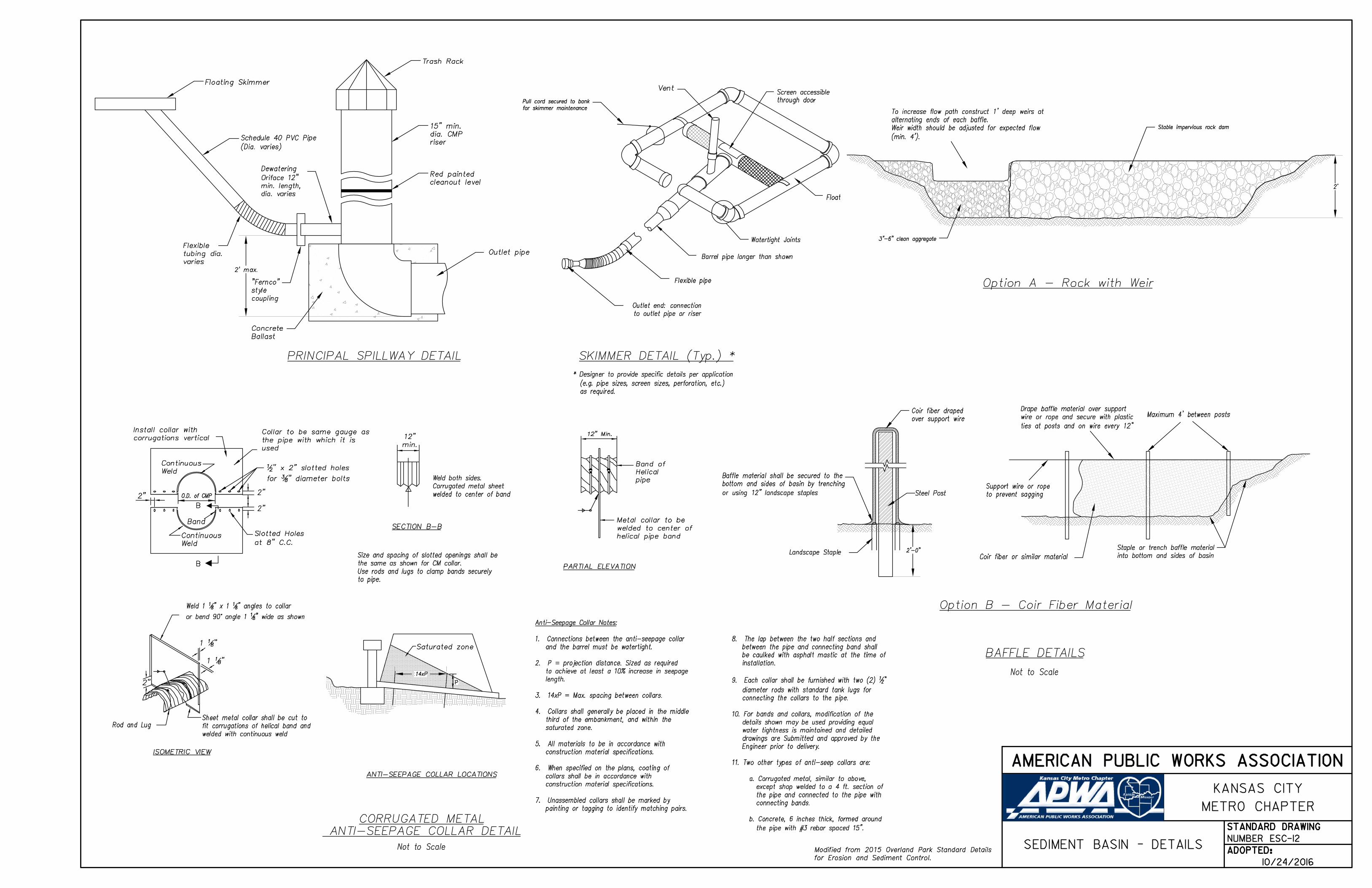
PRINCIPAL SPILLWAY DETAIL
cleanout level
Red painted
2' max.
Outlet pipe
Trash Rack
riser
dia. CMP
15" min.
(Dia. varies)
Schedule 40 PVC Pipe
Floating Skimmer
dia. varies
min. length,
Oriface 12"
Dewatering
coupling
style
"Fernco"
varies
tubing dia.
Flexible
Ballast
Concrete
to outlet pipe or riser
Outlet end: connection
Flexible pipe
Barrel pipe longer than shown
Float
rthrough doo
Screen accessibleVent
SKIMMER DETAIL (Typ.) *
as required.
(e.g. pipe sizes, screen sizes, perforation, etc.)
* Designer to provide specific details per application
for skimmer maintenance
Pull cord secured to bank
Watertight Joints
Steel Post
over support wire
Coir fiber draped
Landscape Staple
or using 12" landscape staples
bottom and sides of basin by trenching
Baffle material shall be secured to the
2'-0"
ties at posts and on wire every 12"
wire or rope and secure with plastic
Drape baffle material over support
Coir fiber or similar material
Maximum 4' between posts
to prevent sagging
Support wire or rope
Option B - Coir Fiber Material
BAFFLE DETAILS
Not to Scale
into bottom and sides of basin
Staple or trench baffle material
(min. 4').
Weir width should be adjusted for expected flow
alternating ends of each baffle.
To increase flow path construct 1' deep weirs at
Option A - Rock with Weir
2'
Stable impervious rock dam
3"-6" clean aggregate
to pipe.
Use rods and lugs to clamp bands securely
the same as shown for CM collar.
Size and spacing of slotted openings shall be
helical pipe band
welded to center of
Metal collar to be
2"
PARTIAL ELEVATION
Weld
Continuous
at 8" C.C.
Slotted Holes
" diameter bolts83for
" x 2" slotted holes21
used
the pipe with which it is
Collar to be same gauge as corrugations vertical
Install collar with
2"
2"
Band
O.D. of CMP
pipe
Helical
Band of
welded to center of band
Corrugated metal sheet
Weld both sides.
SECTION B-B
12" Min.
Weld
Continuous
min.
12"
B
" wide as shown81or bend 90° angle 1
" angles to collar81" x 1 8
1Weld 1
welded with continuous weld
fit corrugations of helical band and
Sheet metal collar shall be cut to
14xP
P
ANTI-SEEPAGE COLLAR DETAIL
CORRUGATED METAL
ISOMETRIC VIEW
ANTI-SEEPAGE COLLAR LOCATIONS
Saturated zone
2"
"811
"811
Rod and Lug
Not to Scale
Anti-Seepage Collar Notes:
1. Connections between the anti-seepage collar
and the barrel must be watertight.
2. P = projection distance. Sized as required
to achieve at least a 10% increase in seepage
length.
3. 14xP = Max. spacing between collars.
4. Collars shall generally be placed in the middle
third of the embankment, and within the
saturated zone.
5. All materials to be in accordance with
construction material specifications.
6. When specified on the plans, coating of
collars shall be in accordance with
construction material specifications.
7. Unassembled collars shall be marked by
painting or tagging to identify matching pairs.
8. The lap between the two half sections and
between the pipe and connecting band shall
be caulked with asphalt mastic at the time of
installation.
9. Each collar shall be furnished with two (2) 12"
diameter rods with standard tank lugs for
connecting the collars to the pipe.
10. For bands and collars, modification of the
details shown may be used providing equal
water tightness is maintained and detailed
drawings are Submitted and approved by the
Engineer prior to delivery.
11. Two other types of anti-seep collars are:
a. Corrugated metal, similar to above,
except shop welded to a 4 ft. section of
the pipe and connected to the pipe with
connecting bands.
b. Concrete, 6 inches thick, formed around
the pipe with #3 rebar spaced 15".
B
for Erosion and Sediment Control.
Modified from 2015 Overland Park Standard Details
NUMBER ESC-12SEDIMENT BASIN - DETAILS
STANDARD DRAWING
ADOPTED:
AMERICAN PUBLIC WORKS ASSOCIATION
METRO CHAPTER
KANSAS CITY
10/24/2016

Depth Min. 12"
Clean Aggregate
2" Min.
Flow
Pipe Culverts together =
Capacity of
Geotextile
:
Stream Channel
Flow
Top of Bank Top of Bank
(*)
Sediment Control BMP
(*)
Sediment Control BMP
(*)
Sediment Control BMP
(*)
Sediment Control BMP
* - Install as shown on plans
ELEVATION
PLAN VIEW
Flo
w
Flo
w
Flow
Flow
Flo
w
detail
See Stream Crossing
Sediment Control
transition
Place Riprap at
(see Note 8)
Flow Barrier
Original Stream Bed
(see Note 8)
Flow Barrier
transition
Place Riprap at
STREAM DIVERSION CHANNEL
(see Note 5)
Channel Lining
TEMPORARY STREAM CROSSING
Notes for Temporary Stream Crossing
care to minimize the amount of sediment lost into the stream.
properly stabilized. Take be shaped to its original cross-section and
7. Upon removal of the structure, the stream and banks shall immediately
without construction equipment working in the channel.
structure and clean-up of the area shall be accomplished
Removal of the bedding and geotextile materials shall be removed.
6. As soon as crossing no longer needed, all structures including culverts,
of compacted aggregate fill.
by at least 12" If multiple culverts are used, they shall be separated
5. The culvert shall be covered with a minimum of 1 foot of aggregate.
length.
the culvert. In no case shall the culvert exceed 40 feet in
upstream and downstream toe of the aggregate placed around
4. The culvert shall extend a minimum of 1 foot beyond the
improves crossing stability.
and bedding material. Filter cloth reduces settlement and
6 inches and a maximum of 1 foot beyond the end of culvert
geotextile shall cover the streambed and extend a minimum of
prior to placement of the pipe culvert and aggregate. The
3. Geotextile shall be placed on the streambed and streambanks
(See Specification for more information).
through the pipes without overtopping the crossing.
(OHW) flows designated in the Contract Documents shall flow
of the stream channel bottom such that ordinary high water
organisms. Additional pipes shall be placed along the remainder
lowest point of the channel to allow the passage of aquatic
2. Place one pipe, buried 6" into the stream bottom, at the
kept to a minimum.
1. Clearing and excavation of the stream bed and banks shall be
re-stabilization of original streambed and banks is completed.
8. Stream should be re-diverted only after backfilling and
prevent or reduce water backup into the construction area.
to divert the stream away from it's original channel and
bags, plywood, or sheet piling shall be used as flow barriers
7. Non-erodible materials such as riprap, Jersey barriers. sand
slopes along with a sediment control BMP.
6. Stream diversion liners shall be entrenched at the top of
be needed along the diversion's length to secure liner.
not be mixed with stream diversion weights. Weights may also
These weights shall allow normal flow of the stream. Soil shall
downstream sides with non-erodible weights such as riprap.
5. Stream diversion liners shall be secured at the upstream and
channel.
depending on the expected velocity and shear stress in the
4. Channel must be lined with riprap or turf reinforcement mat
be sufficient to ensure continuous flow of water in diversion.
grade may be variable, dependent on site conditions, but shal
3. Maximum steepness of side slopes shall be 2H:1V. Depth and
width of existing streambed, whichever is less.
2. Minimum width of bottom shall be 6 feet or equal to bottom
the dry.
work is done in the stream. Construction will be performed in
1. The diversion channel crossing must be operational before
Notes for Temporary Diversion Channel:
for Erosion and Sediment Control.
Modified from 2015 Overland Park Standard Details
Maintenance:
1. Repair stream bank erosion by stabilizing with erosion control
BMPs such as erosion control blankets.
2. For in-stream degradation, armor the culvert outlet(s) with
riprap to dissipate energy.
3. If sediment or debris is accumulating upstream of the crossing,
remove as needed to maintain the functionality of the crossing.
4. If a temporary crossing is requiring excessive maintenance,
replacement with a larger culvert or alternate design may be
necessary.
NUMBER ESC-13
DIVERSION CHANNELS
STREAM CROSSINGS ANDSTANDARD DRAWING
ADOPTED:
AMERICAN PUBLIC WORKS ASSOCIATION
METRO CHAPTER
KANSAS CITY
10/24/2016

Channel Grade
No Overfall
Toe Wall (**)
No Overfall
OUTLET PROTECTION W/O END SECTION
OUTLET PROTECTION WITH END SECTION
Not to Scale
Plan View
Not to Scale
Section A-A
AA
Not to Scale
Section A-A
Not to Scale
Plan View
AA
FlowFlow
Flow Flow
B
B
Not to Scale
Section B-B
Notes:
1. Rock all sides steeper than 3:1.
Apron Width Apron Width
Apron Length
Apron Length
Riprap Depth
Riprap Depth
Apron Width
for Erosion and Sediment Control.
Modified from 2015 Overland Park Standard Details
2. Stabilize all disturbed areas downstream of outlet to the limits
of disturbance.
3. Alternative outlet protection and slope stabilization measures
may be used with approval by the Engineer.
4. Install riprap apron so that it is no higher than flowline of pipe.
5. Reference APWA Specification 2650 for rock type, size, and
placement.
NUMBER ESC-14OUTLET PROTECTION
STANDARD DRAWING
ADOPTED:
AMERICAN PUBLIC WORKS ASSOCIATION
METRO CHAPTER
KANSAS CITY
10/24/2016