Embed Size (px)
Citation preview

IM-P680-02-US Issue 3 1
APT10, APT14, APT14HC and APT14SHC (Closed System) Automatic Pump-Trap Packaged Units
© Copyright 2020
Printed in US
APT10, APT14, APT14HC and APT14SHC(Closed System)
Automatic Pump-Trap Packaged UnitsInstallation and Maintenance Instructions
IM-P680-02-US Issue 3
1. Safety information
2. General product information
3. Installation
4. Commissioning
5. Spare parts and Maintenance
6. Fault finding

IM-P680-02-US Issue 32
APT10, APT14, APT14HC and APT14SHC (Closed System) Automatic Pump-Trap Packaged Units
1. Safety informationSafe operation of these products can only be guaranteed if they are properly installed, commissioned, used and maintained by qualified personnel (see Section 1.11) in compliance with the operating instructions. General installation and safety instructions for pipeline and plant construction, as well as the proper use of tools and safety equipment must also be complied with.
1.1 Intended useReferring to the Installation and Maintenance Instructions, name-plate and Technical Information Sheet, check that the product is suitable for the intended use/application.
i) Check material suitability, pressure and temperature and their maximum and minimum values. If the maximum operating limits of the product are lower than those of the system in which it is being fitted, or if malfunction of the product could result in a dangerous overpressure or overtemperature occurrence, ensure a safety device is included in the system to prevent such over-limit situations.
ii) Determine the correct installation situation and direction of fluid flow.
iii) Spirax Sarco products are not intended to withstand external stresses that may be induced by any system to which they are fitted. It is the responsibility of the installer to consider these stresses and take adequate precautions to minimise them.
iv) Remove protection covers including cardboard support flanges from all connections and protective film from all name - plates, where appropriate, before installation on steam or other high temperature applications.
1.2 AccessEnsure safe access and if necessary a safe working platform (suitably guarded) before attempting to work on the product. Arrange suitable lifting gear if required.
1.3 LightingEnsure adequate lighting, particularly where detailed or intricate work is required.
1.4 Hazardous liquids or gases in the pipelineConsider what is in the pipeline or what may have been in the pipeline at some previous time. Consider: flammable materials, substances hazardous to health, extremes of temperature.
1.5 Hazardous environment around the productConsider: explosion risk areas, lack of oxygen (e.g. tanks, pits), dangerous gases, extremes of temperature, hot surfaces, fire hazard (e.g. during welding), excessive noise, moving machinery.
1.6 The systemConsider the effect on the complete system of the work proposed. Will any proposed action (e.g. closing isolation valves, electrical isolation) put any other part of the system or any personnel at risk? Dangers might include isolation of vents or protective devices or the rendering ineffective of controls or alarms. Ensure isolation valves are turned on and off in a gradual way to avoid system shocks.
1.7 Pressure systems Ensure that any pressure is isolated and safely vented to atmospheric pressure. Consider double isolation (double block and bleed) and the locking or labelling of closed valves. Do not assume that the system has depressurised even when the pressure gauge indicates zero.

IM-P680-02-US Issue 3 3
APT10, APT14, APT14HC and APT14SHC (Closed System) Automatic Pump-Trap Packaged Units
1.8 TemperatureAllow time for temperature to normalise after isolation to avoid danger of burns.
1.9 Tools and consumablesBefore starting work ensure that you have suitable tools and/or consumables available. Use only genuine Spirax Sarco replacement parts.
1.10 Protective clothingConsider whether you and/or others in the vicinity require any protective clothing to protect against the hazards of, for example, chemicals, high/low temperature, radiation, noise, falling objects, and dangers to eyes and face.
1.11 Permits to workAll work must be carried out or be supervised by a suitably competent person. Installation and operating personnel should be trained in the correct use of the product according to the Installation and Maintenance Instructions. Where a formal ‘permit to work’ system is in force it must be complied with. Where there is no such system, it is recommended that a responsible person should know what work is going on and, where necessary, arrange to have an assistant whose primary responsibility is safety.Post ‘warning notices’ if necessary.
1.12 HandlingManual handling of large and/or heavy products may present a risk of injury. Lifting, pushing, pulling, carrying or supporting a load by bodily force can cause injury particularly to the back. You are advised to assess the risks taking into account the task, the individual, the load and the working environment and use the appropriate handling method depending on the circumstances of the work being done.
1.13 Residual hazardsIn normal use the external surface of the product may be very hot. If used at the maximum permitted operating conditions the surface temperature of these products may reach temperatures of 392 °F. These products are not self-draining. Take due care when dismantling or removing the product from an installation (refer to ‘Maintenance instructions’).
1.14 FreezingProvision must be made to protect products which are not self-draining against frost damage in environments where they may be exposed to temperatures below freezing point.
1.15 DisposalUnless otherwise stated in the Installation and Maintenance Instructions, this product is recyclable and no ecological hazard is anticipated with its disposal providing due care is taken.
1.16 Returning productsCustomers and stockists are reminded that under Health, Safety and Environment Law, when returning products to Spirax Sarco they must provide information on any hazards and the precautions to be taken due to contamination residues or mechanical damage which may present a health, safety or environmental risk. This information must be provided in writing including Health and Safety data sheets relating to any substances identified as hazardous or potentially hazardous.

IM-P680-02-US Issue 34
APT10, APT14, APT14HC and APT14SHC (Closed System) Automatic Pump-Trap Packaged Units
2. General product information
2.1 DescriptionThe compact low profile modular pump/trap system consists of the versatile APT10, APT14, APT14HC and APT14SHC Automatic Pumping Trap pre-piped and mounted on a steel base.
The simplex or duplex modules include a condensate reservoir sized to accommodate the pump cycles.
The module requires only service field connections for complete installation and fast startup.
2.2 Typical applicationsThe APT pump/trap modules are used where low profile and high capacity condensate removal is required.
The APT Pump Trap has the features of a conventional F&T trap combined with a pressure powered pump all in one unit.
- Air handlers
- Heat exchangers
- Absorption chillers
- Evaporators
- Dryers
2.3 Standard features- Spirax Sarco non-electric APT10, APT14, APT14HC and APT14SHC Automatic Pump Trap
- Simplex or Duplex units
- Motive steam drip station with Spirax Sarco UTD52L trap, isolation valves and air vent
- Hydrotested and coated with SSI industrial enamel
- Fabricated by ASME Section IX certified welders
- Completely assembled modular pumping system on platform steel base with all connections protected for shipping
Additional options are available
IM-P680-02-US Issue 3 5
APT10, APT14, APT14HC and APT14SHC (Closed System) Automatic Pump-Trap Packaged Units
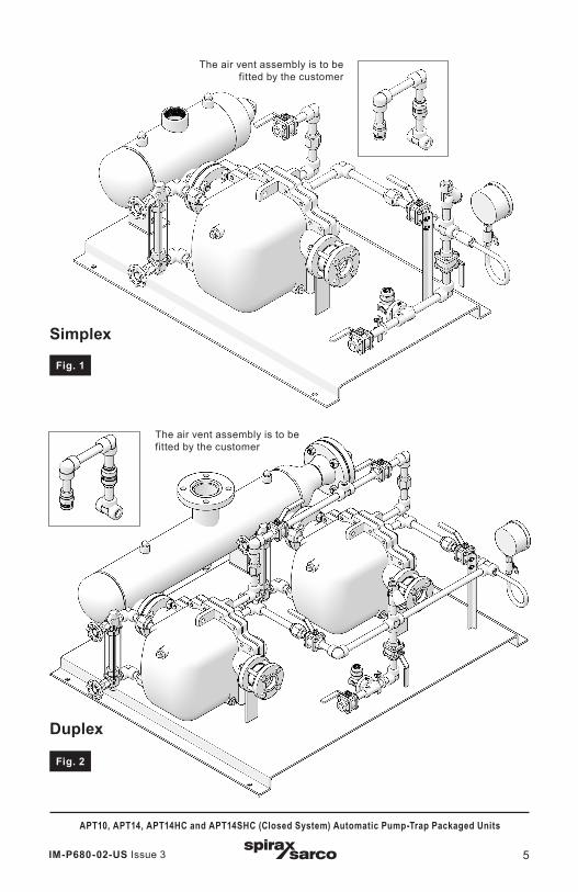
Simplex
Duplex
Fig. 2
The air vent assembly is to be fitted by the customer
The air vent assembly is to be fitted by the customer
Fig. 1

IM-P680-02-US Issue 36
APT10, APT14, APT14HC and APT14SHC (Closed System) Automatic Pump-Trap Packaged Units
2.4 Suggested specifications
APT10
- Furnish and install where shown on plans, Spirax Sarco Inc. model SPT10 Pressure powered pump/trap system.
- The system shall be a complete pre-piped factory package requiring only service connections for a fully functional system.
- Electricity shall not be required for system operation
- The Pump/Trap shall be constructed of Ductile Iron with an allowable operating pressure of 65 psi g.
- The Pump/Trap shall be a unified system with stainless steel mechanism and no external glands or seals. Individual pump and trap systems will not be acceptable
- The package shall be sized to meet (or exceed) the actual required condensate system load.
- The package shall include a structural steel platform skid and painted with 1 coat enamel.
- 3000# fittings with threaded pipe connections included wherever possible.
APT14
- Furnish and install where shown on plans, Spirax Sarco Inc. model SPT4/DPT4 - Pressure powered pump/trap system.
- The system shall be a complete pre-piped factory package requiring only service connections for a fully functional system.
- Electricity shall not be required for system operation
- The Pump/Trap shall be constructed of Ductile Iron with an allowable working pressure of no less than 200 psi g.
- The Pump/Trap shall be a unified system with stainless steel mechanism and no external glands or seals. Individual pump and trap systems will not be acceptable
- The package shall be sized to meet (or exceed) the actual required condensate system load.
- The package shall include a structural steel platform skid and painted with 1 coat enamel.
- 3000# fittings with threaded pipe connections included wherever possible.
APT14HC
- Furnish and install where shown on plans, Spirax Sarco Inc. model SPT4HC/DPT4HC- Pressure powered pump/trap system.
- The system shall be a complete pre-piped factory package requiring only service connections for a fully functional system.
- Electricity shall not be required for system operation
- The Pump/Trap shall be constructed of Ductile Iron with an allowable working pressure of no less than 200 psi g.
- The Pump/Trap shall be a unified system with stainless steel mechanism and no external glands or seals. Individual pump and trap systems will not be acceptable
- The package shall be sized to meet (or exceed) the actual required condensate system load.
- The package shall include a structural steel platform skid and painted with 1 coat enamel.
- 3000# fittings with threaded pipe connections included wherever possible.

IM-P680-02-US Issue 3 7
APT10, APT14, APT14HC and APT14SHC (Closed System) Automatic Pump-Trap Packaged Units
APT14SHC
- Furnish and install where shown on plans, Spirax Sarco Inc. model SPT4SHC- Pressure powered pump/trap system.
- The system shall be a complete pre-piped factory package requiring only service connections for a fully functional system.
- Electricity shall not be required for system operation
- The Pump/Trap shall be constructed of Ductile Iron with an allowable working pressure of no less than 200 psi g.
- The Pump/Trap shall be a unified system with stainless steel mechanism and no external glands or seals. Individual pump and trap systems will not be acceptable
- The package shall be sized to meet (or exceed) the actual required condensate system load.
- The package shall include a structural steel platform skid and painted with 1 coat enamel.
- 3000# fittings with socket weld pipe connections included wherever possible.
- Valves greater than 1" to be carbon steel ANSI 150 flanged. Valves smaller than 1" to be 800# forged steel.
2.5 Typical construction
APT10
Model SPT10
PMO – Motive pressure 65 psi g
Design pressure (PMA) 145 psi g @ 392°F
Design temperature (TMA) 392 °F
Capacity range * Trap mode - max 2022 lb/hrPump mode - max 1420 lb/hr
Hydrotest pressure 100 psi g
Construction materials
Receiver vessel - Fabricated steelAPT 10-4.5 - See SSI Technical sheets TI-5-2301-USValves - ANSI 150 Carbon steel ball valves, 800# forged steel gate valvesPiping: 2" and under Sch 80
>2" Sch 40
Dimensions and weight See SSI sales drawings

IM-P680-02-US Issue 38
APT10, APT14, APT14HC and APT14SHC (Closed System) Automatic Pump-Trap Packaged Units
APT14
Model SPT4/DPT4
PMO 200 psi g
Design pressure (PMA) 230 psi g @ 300 °F
Design temperature (TMA) 482 °F
Capacity range ** Trap mode - max 8800 lb/hrPump mode - max 2420 lb/hr
Hydrotest pressure 300 psi g
Construction materials
Receiver vessel - Fabricated steelAPT14 - See SSI Technical sheets TI-5-228-USValves - ANSI 150 Carbon steel ball valves, 800# forged steel gate valvesPiping: 2" and under Sch 80
>2" Sch 40
Dimensions and weight See SSI sales drawings
APT14HC
Model SPT4HC/DPT4HC
PMO 200 psi g
Design pressure (PMA) 230 psi g @ 300 °F
Design temperature (TMA) 482 °F
Capacity range ** Trap mode - max 19,800 lb/hrPump mode - max 6160 lb/hr
Hydrotest pressure 300 psi g
Construction materials
Receiver vessel - Fabricated steelAPT 14HC - See SSI Technical sheets TI-5-228-USValves - ANSI 150 Carbon steel ball valves, 800# forged steel gate valvesPiping: 2" and under Sch 80
>2" Sch 40
Dimensions and weight See SSI sales drawings
APT14SHC
Model SPT4SHC
PMO 200 psi g
Design pressure (PMA) 230 psi g @ 300 °F
Design temperature (TMA) 482 °F
Capacity range ** Trap mode - max 19,800 lb/hrPump mode - max 6160 lb/hr
Hydrotest pressure 300 psi g
Construction materials
Receiver vessel - Fabricated steel APT 14HC - See SSI Technical sheets TI-5-228-US Valves - ANSI 150 Carbon steel gate valves, 800# forged steel gate valves Piping: 2" and under Sch 80
>2" Sch 40
Dimensions and weight See SSI sales drawings
*Based on 39" installation head, 65 psi g motive steam, 21 psi g back pressure.**Based on 39" installation head, 73 psi g motive steam, 15 psi g back pressure.
2.5 Typical construction (continued)

IM-P680-02-US Issue 3 9
APT10, APT14, APT14HC and APT14SHC (Closed System) Automatic Pump-Trap Packaged Units
2.6 CapacityFor sizing data, see APT Selection and capacity chart TI-5-204-1-US.
3. Installation
Safety Notes:Before actioning any installation, observe the ‘Safety Information’ in section 1.
3.1 Lifting, in one or two waysIt is intended that the APT is moved by using a fork lift under the base plate to raise and finally place where required, or, through the use of suitable lifiting eyes that can be fitted to the lower lifting holes provided at each corner of the base plate (see Figure 7).Under no circumstances should the unit be lifted by either the receiver or integral pipework.
½" holes provided for the use of suitable lifting eyes and anchor bolts. Rectangle holes can be used for lifting straps.
Fig. 3
½" holes provided for the use of suitable lifting eyes and anchor bolts. Rectangle
holes can be used for lifting straps.
IM-P680-02-US Issue 310
APT10, APT14, APT14HC and APT14SHC (Closed System) Automatic Pump-Trap Packaged Units
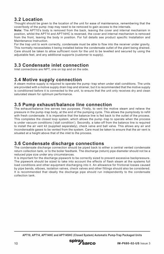
3.2 LocationThought should be given to the location of the unit for ease of maintenance, remembering that the cover/body of the pump - trap may need to be removed to gain access to the internals. Note: The APT10’s body is removed from the back, leaving the cover and internal mechanism in position, whilst the APT14 and APT14HC is reversed, the cover and internal mechanism is removed from the front, leaving the body in position. For full details see product specific Installation and Maintenance Instruction.For the trap unit to work correctly, condensate must be able to flow into the receiver under gravity. This normally necessitates it being installed below the condensate outlet of the plant being drained. Care should be taken to allow sufficient room for the unit to be levelled and secured by using the adjustable feet, and any additional supports (customer to supply).
3.3 Condensate inlet connectionInlet connections are NPT, one on top and on the side.
3.4 Motive supply connectionA steam motive supply is required to operate the pump - trap when under stall conditions. The units are provided with a motive supply drain trap and strainer, but it is recommended that the motive supply is conditioned before it is connected to the unit, to ensure that the unit only receives dry and clean saturated steam for optimum performance.
3.5 Pump exhaust/balance line connectionThe exhaust/balance line serves two purposes. Firstly, to vent the motive steam and relieve the pressure in the pump -trap body, at the end of the pumping cycle. This allows the pump body to refill with fresh condensate. It is imperative that the balance line is fed back to the outlet of the process. This completes the closed loop system, which allows the pump - trap to operate when the process is under vacuum conditions (‘stall condition’). Secondly, a take-off from the balance line is required to install the air vent kit (supplied separately), check valve and ball valve. This allows any air and incondensable gases to be vented from the system. Care must be taken to ensure that the air vent is situated at a height above that of the inlet to the process.
3.6 Condensate discharge connections The condensate discharge connection should be piped back to either a central vented condensate return collection tank, or to the boiler feedtank. The discharge (return) pipe diameter should not be a reduced pipe size under any circumstances.It is important for the discharge pipework to be correctly sized to prevent excessive backpressure. The pipework should be sized to take into account the effects of flash steam at the systems full load conditions and other equipment discharging into it. An allowance for frictional losses caused by pipe bends, elbows, isolation valves, check valves and other fittings should also be considered. It is recommended that ideally the discharge pipe should run independently to the condensate collection tank.

IM-P680-02-US Issue 3 11
APT10, APT14, APT14HC and APT14SHC (Closed System) Automatic Pump-Trap Packaged Units
Condensate return
Condensate discharge pipe
Process
The exhaust and balance lines are to be supplied by others.Fig. 4
Motive inlet
Water outlet
Water inlet
Steam inlet
Field installed piping of loose air vent assembly
Motive exhaust/balance line
3.7 Control of motive supply pressureAlthough the APT’s are able to utilise motive pressures up to 200 psi g for the APT14, APT14HC and APT14SHC and 65 psi g for the APT10, it is recommended that the motive supply pressure does not exceed 29 - 58 psi g above the backpressure applied to the pump. When specifying a pressure reducing valve to reduce the motive supply pressure, the effects of pulsating flow must be considered. Contact Spirax Sarco for details of recommended installation if required. Pump life can be increased by using lowest motive pressure necessary to meet the required duty.
3.8 Pressure gaugesIt is highly recommended that pressure gauges are fitted to the motive supply, condensate outlet and inlet. A tapping on the pump body is also provided to fit a pressure gauge (refer to pump IMI).

IM-P680-02-US Issue 312
APT10, APT14, APT14HC and APT14SHC (Closed System) Automatic Pump-Trap Packaged Units
4.1 After ensuring the inlet, exhaust, discharge, motive supply and exhaust lines are coupled in accordance with Figure 7, slowly open the motive supply inlet valve (C) to supply pressure to the APT10, APT14 and APT14HC and APT14SHC. Ensure that the exhaust/balance line is open (R) and not restricted in any way.
4.2 Slowly open the motive supply drain trap isolation valves (U), to ensure the motive supply steam is kept dry.
4.3 Slowly open the isolation valves in the condensate inlet (A) and discharge (G) lines, allowing the condensate to fill the body of the pump - trap.
4.4 The APT is now ready for operation.
4.5 The process steam supply line (equipment that the APT package is draining) can now be slowly opened (X) to allow the process to start.
4.6 Check there are no leaks from any of the APT connections.
4.7 Check that the pressure gauges (customer supply) are not showing pressures above the maximum operating pressures of the APT.
4.8 Observe operation for any abnormalities, remembering that the APT will only pump when there is insufficient differential to remove the condensate from the process. At all other times the APT should be in the trapping mode and may set at a constant discharge rate. If any irregularities are observed, recheck that the installation is as recommended in Section 3, then consult the Fault finding guide in Section 6.
4. Commissioning
Fig. 5
Condensate return
Condensate discharge pipe
Process
The exhaust and balance lines are to be supplied by others.
Motive inlet
Water outlet
Water inlet
Steam inlet
Field installed piping of loose air vent assembly
Motive exhaust/balance line

IM-P680-02-US Issue 3 13
APT10, APT14, APT14HC and APT14SHC (Closed System) Automatic Pump-Trap Packaged Units
5.1 Spare partsThe main component products such as the APT, isolating valves and strainers etc; are available as complete separate products. Individual spares for these are also available if required. See product specific Technical Information sheets (TI) or Installation and Maintenance Instructions (IM) for complete spares listing. Pipework sub-assemblies can also be supplied by special order, contact Spirax Sarco for details.Note: Flange gaskets, jointing paste/tape and flange nuts and bolts are not available as spares.
5.2 Maintenance:- Before any installation or maintenance procedure, always ensure that all steam or condensate
lines are isolated. Ensure any residual internal pressure in the product or connecting lines is carefully relieved. Also ensure any hot parts have cooled to prevent risk of injury from burns.Always wear appropriate safety clothing before carrying out any installation or maintenance work.
- Before commencing any maintenance ensure, all relevant permits to work have been obtained and completed.
- Spare parts for component products are available. For full details and fitting/maintenance instructions see separate relevant Installation and Maintenance Instructions (IM).
- If the unit is to be removed from the installation, ensure the lifting instructions are followed, detailed in Section 1 and Section 3.1.
5. Spare parts and maintenance

IM-P680-02-US Issue 314
APT10, APT14, APT14HC and APT14SHC (Closed System) Automatic Pump-Trap Packaged Units
CautionInstallation and trouble shooting should only be performed by qualified personnel. Before any maintenance is attempted, ensure any residual internal pressure in the product or connecting lines is carefully relieved. Also ensure any hot parts have cooled to prevent risk of injury from burns. Always wear appropriate safety clothing before carrying out any installation or maintenance work.
The APT10-PPU, APT14 and APT14HC are thoroughly tested before leaving the factory. This includes a comprehensive functional test. If the unit has failed to operate it is likely that an installation problem could exist. Please check the following before commencing with the trouble-shooting chart.
6.1 Trouble areas to check first- Are all isolating valves open?
- Is the condensate inlet strainer clean and free from debris?
- Is the motive supply strainer clean and free of debris?
- Is the available motive pressure higher than the total backpressure? (recommended 44 to 58 psi g but not exceeding 200 psi g for the APT14 and APT14HC and 65 psi g for the APT10.
- Is the exhaust balance line connected to the outlet of the equipment being drained and is it free from obstruction (refer to the installation diagram Figure 11)
- Is the direction of flow through the unit correct, indicated by the flow arrow?
6.2 Quick reference trouble-shooting guideSYMPTOM APT fails to operate on start-up.
CAUSE 1 No motive presure.
CHECK and CURE Motive supply pressure exceeds total backpressure. Verify motive strainer is clean.
CAUSE 2 Inlet isolation valve maybe closed.
CHECK and CURE Inlet pipe is free from obstructions and the isolation valve is open.
CAUSE 3 Motive inlet and exhaust lines incorrectly connected.
CHECK and CURE Motive = C, Exhaust = E.
CAUSE 4 The rate of condensate produced by the process maybe very low, causing the APT to cycle slowly.
CHECK and CURE The process being drained is operating correctly.
SYMPTOM Equipment flooded - but APT appears to cycle normally.
CAUSE 1 APT is undersized for the application.
CHECK and CURE Check system parameters agree with the custom sizing sheet/graph.
6. Fault finding guide

IM-P680-02-US Issue 3 15
APT10, APT14, APT14HC and APT14SHC (Closed System) Automatic Pump-Trap Packaged Units
6.2 Quick reference trouble-shooting guide (continued) SYMPTOM Equipment flooded and APT has stopped cycling.
CAUSE 1 Blocked exhaust line.
CHECK and CURE Balance line is free from obstruction or isolated.
CAUSE 2 Blocked condensate inlet line.
CHECK and CURE Firstly check that the inlet line is not isolated. Secondly check and clean the strainer mesh for blockages.
CAUSE 3 Blocked condensate outlet line.
CHECK and CURE Firstly check that the outlet line is not isolated. Secondly check and clean the strainer mesh for blockages.
CAUSE 4 Damaged mechanism.
CHECK and CURE See seperate Installation and Maintenance Instructions (IM) for the pump - trap
CAUSE 5 No motive steam available.
CHECK and CURE Steam supply to APT is available and at the correct pressure. Motive pressure must exceed total backpressure. Ensure motive supply strainer is clear of debris. Clean or replace if necessary.
CAUSE 6 Leaking motive inlet valve.
CHECK and CURE If the APT body is hot (observe safety information in Section 1), this indicates the APT’s mechanism is stuck on the discharge cycle. Check mechanism for excessive friction as per Section 6. See seperate Installation and Maintenance Instructions (IM) for the pump - trap.
CAUSE 7 Broken spring.
CHECK and CURE If the APT body is cold, this indicates the APT’s mechanism is stuck on the filling cycle. See seperate Installation and Maintenance Instructions (IM) for the pump - trap.
CAUSE 8 Blocked condensate inlet line.
CHECK and CURE Inspect and clean the filter, check for blockages.
SYMPTOM Chattering or banging of the APT during cold start-up.
CAUSE 1 Hydraulic pulsing of the inlet check valve.
CHECK and CURE Reduce installation head to APT - throttle valve on APT - PPU condensate inlet.
SYMPTOM Chattering or banging in the return line after APT discharges.
CAUSE 1 Live steam entering discharge line.
CHECK and CURE Ensure that the steam trap draining the motive supply line is working correctly.
CAUSE 2 Motive pressure too high.
CHECK and CURE For optimum capacity and performance, the motive pressure should not exceed 29-58 psi g above the total backpressure (differential pressure). Reduce the motive pressure using a suitable pressure reducing valve,taking into account the effects of cyclic flow.

IM-P680-02-US Issue 316
APT10, APT14, APT14HC and APT14SHC (Closed System) Automatic Pump-Trap Packaged Units