Embed Size (px)
Citation preview

APT 2.0
Simon Dawes & Keith RickardUpdate 1

What is the APT?Automatic Photometric Telescope
Built by Jack Ells in 1984 (based on JBAA)
AutomaticOnce set-up it continues to observe the same stars over and over, corrects for tracking problems, recognises cloud.
PhotometricUses a photomultiplier tube and 24 bit counter (256^3 – 3 x 8 bit counters) to measure star brightness
TelescopeDuh…

Why 2.0The APT has been out of commission for about 5 years• The fluid light guide went opaque - a generous gift from the
BAA enabled us to buy a new one.• The BBC Model B used to control the telescope stopped
working - it was a rare 64kB version and the National Museum of Computing generously swapped it for a working model they had.
• The drives failed, the 20 year old soldering failed and was rewired by an ESA engineer
• The BBC Model B software keeps crashing• Moving Data off of the APT (if it was working) requires
manual transcription

2.0 Approach
Concepts• Computing Platform Agnostic• Interface platform well established and
supported• Simple User Interface• Simple to use• Smaller footprint

2.0 Approach
Why keep the PMT and not use a CCD camera?• A more complex solution is required (e.g. laptop
and imaging software)• Additional cost• PMT provides instant results - a CCD requires
post-processing time and effort• PMT can be accruate to a few 1000ths of a
magnitude

Main Components of the APT
• 8 1/2 inch Newtonian reflector• Flip mirror• Light Guide• Photomultiplier Tube (PMT)• Filter wheel• Amplifier/Discriminatior• PMT pulse Counter• Stepper motors and control box• Computer system

Currently...
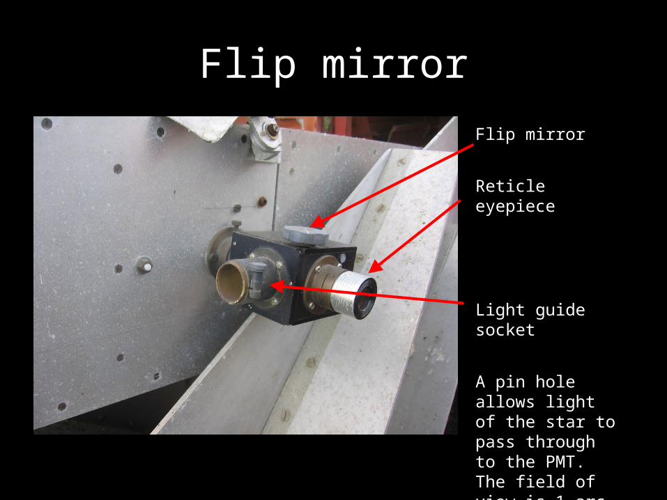
Flip mirrorFlip mirror
Reticle eyepiece
Light guide socket
A pin hole allows light of the star to pass through to the PMT. The field of view is 1 arc minute.

Mission ControlMonitor
BBC Micro B computer (64K RAM)
Two 5 1/4" floppy disk drives
PMT pulse counters
Stepper motor control box
900v DC power supply
PMT amplifier and discriminator box
Photomultiplier tube (PMT)

Stepper motor box

Inside the control boxResistor heat sink
2 x Stepper motor control boards
Sockets for stepper motor leads
240V AC to 30V DC transformer
BBC Micro B cable connector socket
note: wiring rebuilt by Mark

Photomultiplier tube900V power supply
Photomultiplier tube (PMT) enclosure
Amplifier and discriminator box
Filter wheel
Light guide hole

Amplifier and DiscriminatorConnector for PMT
cable
+12v/-12v power socket
Connector to PMT Pulse Counter box

PMT Pulse CounterAmplifier/Discriminator cable connector
BBC interfacing chip
Counters (count up to 16,777,216 pulses)
Cable to BBC Micro B interface port
5 volt supply from BBC Micro B computer

Introducing the Raspberry Pi and the Arduino Uno

Raspberry Pi• 256MB RAM (BBC has 64K!)• 600 Mhz (BBC runs at 2Mhz!)• Runs under Linux (like Windows but free and open source)• Operating system runs from an SD Card instead of a hard disk• 2 x USB ports (for mouse, keyboard and other devices!)• GPIO port• Runs off 5V at 700ma• Costs around £33
Also has
• Ethernet port for connection to a network
• HDMI & composite video output
• Audio output

Arduino Uno
• 32K Flash memory• 2K RAM• Runs at 16mhz• 20 input and output pins which can be used to directly
control electronic devices• USB port which is presented to connecting device as a serial
port• Runs off 5 - 12V, max 1000ma• Costs around £15

2.0 Architecture
RPi(Master)
RA Drive
DEC Drive
PMT
Controller
counter
Arduino(Slave)
Arduino(Slave)
Keypad
LCD
Buzzer
• The programming language for the Arduinos is C++
• Raspberry Pi will be the "brains" of the operation and will control the two Arduinos by instructing them what to do, operate the user interface, store data from the PMT, etc. The program is being written in Python.
The RPi and Arduinos will be powered by a USB hub

Connecting to the stepper motor control boards
The Arduino will be housed in the stepper boards box and connected to this board

Connecting to the PMT pulse counters
This is the only bit that is required.
These counter chips will be placed on a small circuit board known as a "shield" on the Arduino and housed in the stepper boards box

Hand Box
Will contain a red lit 2x16 character LCD
Will aim to have the keypad backlit in red

Software
~15% complete; 1235 lines of code-No user interface (no keyboard, mouse or monitor!)
- Controlled by pre-built files and user input/output via a hand controller
-Arduino's controlled by bespoke 'language' invented by Keith and Simon, currently 31 commands.

Spiral Search
We are keeping many concepts in the original software such as the spiral search. This will be managed by the Python software

Find Sky* = Done
Find CheckHA 18.8:DEC 73.1
Find ComparisonHA 18.8:DEC 73.1
1. APT 2.0 MenuPress *
Select VariablePress *,2,4 or #
Select ObserverPress *,2,4 or #
CommissionPress *,2,4 or #
AboutPress *,2,4 or #
Z CamPress *,2,4 or #
cycle through objects in objectlist.csv
Find VariableHA 18.8:DEC 73.1
# #
6 6 6
4 4 4
#*
*
#*
During this sequence:1)The arrow keys are available to slew the scope. 2)The A,B,C keys change the slew speed3)* moves on in the sequence4) # exits the sequence back to 'Select Variable'
Current Menu Structure

End