Embed Size (px)
Citation preview

www.em.doe.gov safety performance cleanup closure
E M Environmental Management
1
April 30, 2013

www.em.doe.gov safety performance cleanup closure
E M Environmental Management
2
• After facilities are turned over by USEC and accepted by DOE:
• Perform minimal stabilization and deactivation activities for facilities to
put into safe configuration for long-term S&M.
• Submit a Stabilization and Deactivation Plan.
• Perform the necessary facility stabilization and deactivation activities
including, but not limited to, the following:
Evaluate and determine the need for the continued safety
requirements for monitoring and/or maintaining systems.
Perform deactivation and/or verification activities that support
facilities stabilization, per DOE O 420.1B, Facility Safety and
contractor safety basis documentation.
Perform uranium deposit/hold-up removal or Tc-99 treatment
necessary to minimize long-term S&M cost.
Facility Stabilization and Deactivation C.1.3 - (Period 3)

www.em.doe.gov safety performance cleanup closure
E M Environmental Management
3
Goal for S&M and Utility Operations
Goal is to achieve for
approximately 2/3
reduction in cost of
S&M Program

www.em.doe.gov safety performance cleanup closure
E M Environmental Management
4
• Due to enormous surface area of the uranium process systems within
the Paducah cascade, a significant amount of uranium has been
chemically and physically absorbed to the inner walls of the piping and
cell components (commonly referred to as hold-up)
• It has been estimated as much as 7,500 kgs of uranium may be present.
• Uranium deposits are also caused by wet air in leakage.
The moisture in the air upon entering the cascade reacts with UF6 to
form various uranium oxy-fluorides with the most common being
UO2F2 and are deposited near the leak.
The uranium deposits can range from a few pounds caused by seal
failures to several hundred pounds from expansion joints.
It is estimated to be approximately 5,000 lbs of UO2F2 within the
cascade.
Facility Stabilization and Deactivation C.1.3.1 - Uranium Hold-up/Deposits

www.em.doe.gov safety performance cleanup closure
E M Environmental Management
5
Estimates have been made that approximately 540 to 550 kilograms of Tc-
99 were fed into the PGDP cascade between 1953 and 1977.
Approximately 325 kgs were fed into the cascade during period 1953
to 1962.
Approximately 214 kgs were fed into the cascade during the period
1962 to 1983.
No Tc-99 was fed into the cascade during the period 1983 to present.
Facility Stabilization and Deactivation C.1.3.1 - Technetium-99

www.em.doe.gov safety performance cleanup closure
E M Environmental Management
6
The first large scale CIP began in 1956 and concluded in 1962.
• Most all of the stages were removed, cleaned or decontaminated and
new barrier installed in the first cascade improvement program which
was concluded in July 1962.
The second CIP began in 1975 and concluded in 1983.
• The converters were replaced in the purge cascade with converters
obtained from K-27 in Oak Ridge. Tc-99 should have been less than
what was present on the existing purge cascade converters at that time
because of the anticipated higher levels of Tc-99 in the Paducah purge
cascade at that time.
• Approximately 11 kgs of Tc-99 were removed by MgF2 traps located in
C-310 purge cascade in a 10-month period of time. It is uncertain how
many trap change outs were performed.
Facility Stabilization and Deactivation C.1.3.1 - Technetium-99 (Cont.)
www.em.doe.gov safety performance cleanup closure
E M Environmental Management
7
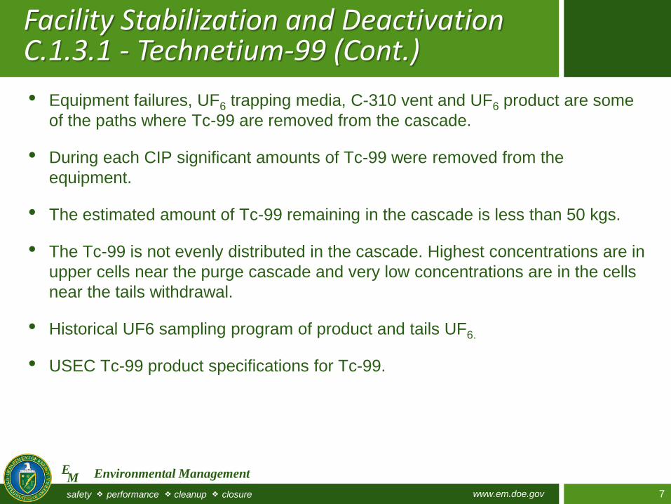
• Equipment failures, UF6 trapping media, C-310 vent and UF6 product are some
of the paths where Tc-99 are removed from the cascade.
• During each CIP significant amounts of Tc-99 were removed from the
equipment.
• The estimated amount of Tc-99 remaining in the cascade is less than 50 kgs.
• The Tc-99 is not evenly distributed in the cascade. Highest concentrations are in
upper cells near the purge cascade and very low concentrations are in the cells
near the tails withdrawal.
• Historical UF6 sampling program of product and tails UF6.
• USEC Tc-99 product specifications for Tc-99.
Facility Stabilization and Deactivation C.1.3.1 - Technetium-99 (Cont.)
www.em.doe.gov safety performance cleanup closure
E M Environmental Management
8
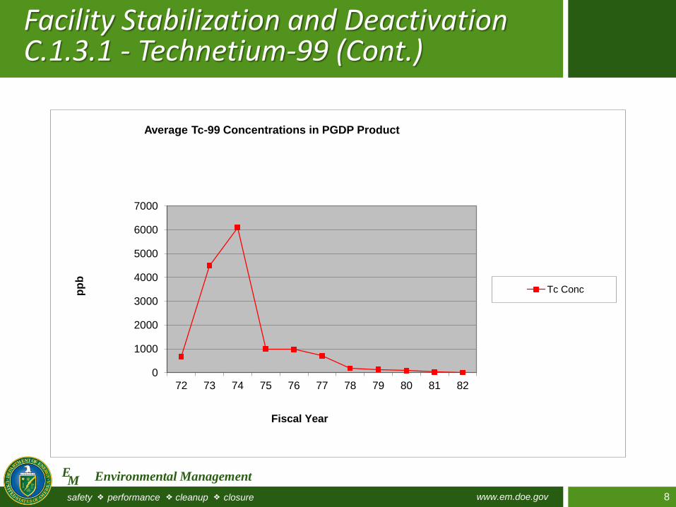
Facility Stabilization and Deactivation C.1.3.1 - Technetium-99 (Cont.)
0
1000
2000
3000
4000
5000
6000
7000
72 73 74 75 76 77 78 79 80 81 82
pp
b
Fiscal Year
Average Tc-99 Concentrations in PGDP Product
Tc Conc

www.em.doe.gov safety performance cleanup closure
E M Environmental Management
9
• Ensure decisions for optimizing utilities and laboratory services are
based on documented cost/benefit analyses that evaluate overall costs
to DOE.
• Use energy savings performance contracts to the maximum extent
possible where determined to be cost effective.
• Support the continued analytical services to the DUF6 Conversion Plant,
the on-going environmental remediation and other site
tenants/contractors.
• Use/need of utilities for its operations is minimized to the maximum
extent and work aggressively to isolate and shutdown GDP and
associated support facilities at the site.
• Submit and implement a Utility Optimization Program Plan consistent
with the Federal Energy Management Program and DOE Order O 436.1,
where applicable.
Facility Stabilization and Deactivation C.1.3.2 - Utility Optimization (Period 3)

www.em.doe.gov safety performance cleanup closure
E M Environmental Management
10
C-611 Water Treatment and Distribution Facilities
The C-611 Water Treatment System provides
the water supply to the Paducah Site.
Currently, an average 26 million gallons per day
(mgd) is required with a peak of 30 to 32 mgd
usage.
The water treatment process is based on
conventional water treatment techniques which
include softening, coagulation, flocculation,
sedimentation, and chlorination. Raw water is
obtained from the Ohio River through an intake
station and pumped through water-softening
units at the facility.
Assess the capabilities for purposes of transferring these DOE assets to local
community water districts or for deactivating the on-site water treatment facilities and
relying solely on community water districts water supplies.
Assess the site’s near-term and long-term DOE operational needs.

www.em.doe.gov safety performance cleanup closure
E M Environmental Management
11
C-615 Sewage Disposal Plant
The C-615 Sewage Disposal Plant provides the
sewage handling and treatment for the Paducah
Site.
Sewage is handled by four 400 gallons per minutes
(gpm) basin pumps and 75 gpm sludge pumps
which provide a basic plant capacity of 350 gpm.
Normal flow is between 200 and 300 gpm.
The sewage collection system services all the
occupied plant buildings with the exception of some
remote facilities.
The plant consists of chemical, mechanical, and
biological treatment prior to discharge.
The pant provides secondary treatment. It consists
of a comminutor, primary and secondary settling
basins, trickling filter, sludge digester and settling
beds, chlorinator, and contact chamber.
Assess the capabilities of the on-site sewage collection and treatment systems and
facilities for purposes of replacing these facilities through use of more efficient modular
treatment systems or use of local community sewage treatment districts.
Assess the site’s near-term and long-term DOE operational needs.

www.em.doe.gov safety performance cleanup closure
E M Environmental Management
12
• Assess the capabilities and configuration of the on-site power distribution system and
facilities for purposes of:
1) consolidating on-site power distribution to the C-531 Switchyard as quickly as
possible,
2) evaluating and determining if construction/installation of a replacement switchyard(s)
(high and low side) is cost effective,
3) transferring options or ownership of the four existing switchyards (C-531, C-533, C-
535, C-537), two relay houses (C-532, C-536), and other related support
systems/facilities to electrical utilities.
• Assess the site’s near-term and long-term DOE operational needs.
• As radiological and PCB contamination exists in the switchyards and on/near associated
support facilities and assets, any recommendation must ensure appropriate controls are in
place to properly control contaminants and ensure protection of personnel entering or
commercially utilizing the facilities and systems.
Power Distribution

www.em.doe.gov safety performance cleanup closure
E M Environmental Management
13
Power Distribution Switchyards
13 13 13
C-531, C-533, C-535, and C-537 switchyards
contain the 161kilovolt (kV) electrical system
components necessary for operation of the PGDP.
The plant typically uses between 900 megawatts
and 2000 megawatts of electrical power per hour,
depending on the plant’s production targets and
availability of reasonably priced power.
The plant was built with the capacity to use up to
3000 megawatts.
Electrical power comes into the plant at 161,000
volts through the overhead transmission lines from
TVA’s Shawnee Steam Plant and Electric Energy,
Inc. (EEI) at Joppa, Illinois.
The power flows through more than 80 circuit
breakers to large transformers (35) located
throughout the plant.

www.em.doe.gov safety performance cleanup closure
E M Environmental Management
14
Of the eighteen transmission
lines entering the PGDP,
twelve are owned by the
Tennessee Valley Authority
(TVA) and six are owned by
EEI.
Kentucky Utilities owns one
line that comes to the plant
and goes out but does not
provide feed to the plant.
In addition the four PGDP
switchyards are connected
by five 161kV tie lines
owned by DOE and leased
by USEC.
Power Distribution Switchyards

www.em.doe.gov safety performance cleanup closure
E M Environmental Management
15
C-600 Steam Plant Shutdown
The plant produces steam used to heat, vaporize UF6,
obtain UF6 samples, maintain process temperatures,
clean equipment, and provide heat for other
miscellaneous buildings and process operations.
It consists of three water wall tube boilers (two coal-
fired and one oil-and gas-fired) each capable of
producing 100,000 pounds of steam per hour at 250
pounds per square inch plus associated equipment.
Some of the site facilities such as C-100, C-300, and
C-710 currently utilize the chilled water system for
building air conditioning and the steam for heating.
The use of electrostatic precipitators and low-sulpher
coal helps the plant keep atmospheric emissions
below environmental limits. The steam plant uses
approximately 35,000 tons of coal per year.
Deactivate and shutdown the C-600 Steam Plant. However, heat, compressed air,
nitrogen, and chilled water will still be required for certain facilities that currently utilize the
RCW system (residual heat).
Evaluate the site’s need (including tenants/contactors) for heat, compressed air, nitrogen
and chilled water, which will include alternate sources, properly sized, for the utilities and
upon approval by DOE, implement the modifications.

www.em.doe.gov safety performance cleanup closure
E M Environmental Management
16
Alternative
Heat and Chilled Water Systems
16 16
Systems were designed and built to pump heated
recirculating cooling water (RCW) from the process
buildings to the buildings requiring space heating.
The pumped water is known as recirculating heating water
(RHW).
Shutdown of the gaseous diffusion process will result in
loss of waste heat source, RCW and RHW, and the
internal radiant heat from the process within each
buildings.
Steps must be taken to provide alternate sources of heat
or to winterize the buildings if the uranium enrichment
process is shutdown.
Provide a provision of an alternative heat supply to the facilities currently utilizing waste
heat for facility heating systems.
Evaluate modifications to the chilled water system to provide air conditioning for the C-
100, C-101, C-102, C-200, C-300, C-400 office areas, C-710 and C-720 office areas
that are currently cooled.
Facility modifications should be sized and installed only for these facilities/areas which
the Contractor (or the other site’s contractors/tenants) expects to utilize for support of
this PWS.

www.em.doe.gov safety performance cleanup closure
E M Environmental Management
17
Analytical Laboratory
The C-709 Plant Laboratory Annex and the C-
710 Technical Services Building house
laboratories with an array of modern analyzers
and test equipment, offices, a conference room,
and vault for records retention and storage.
The laboratory facilities analyze over 100,000
various types of analytical tests per year, such
as analyzing for metals, radiological, organics,
inorganics, volatiles, and semivolatiles.
Media types such as groundwater, concrete,
soil, air, waste waters are processed through the
laboratory, also supporting the environmental
cleanup programs.
Assess the capabilities of the on-site Analytical Laboratory (C-709 and C-710) for
purposes of privatization of the facilities and equipment.
Assess the need of analytical services (lease, transfer, or purchase) from existing on-site
tenants/contractors to determine the type of analytical services needed.