Embed Size (px)
Citation preview

Product Data SheetPS-00371, Rev K
April 2018
Micro Motion® T-Series Coriolis Flow andDensity Meters
Superior flow measurement in a single straight tube flow meter
■ Built-in balance bar provides the best single straight tube mass flow measurement to reduce variability inprocess control
Comprehensive hygienic application coverage
■ Easy to CIP and SIP with EHEDG certified, 3-A authorized, ASME BPE design■ Diameter matches standard process tubing for draining in any orientation■ Fast product change-over with self-draining design and no profile effects■ Single flow path is easy to clean mechanically■ Highly-polished surface finish for ultra-pure fluids
Superior reliability
■ No moving parts to wear or replace minimizes maintenance for long-term reliability■ Full secondary pressure containment available
Micro Motion® T-Series Coriolis Flow and DensityMetersMicro Motion® Coriolis meters meet a vast range of application needs, ranging from extreme low-flow up to high-flow, high-capacity lines. Cryogenic, hygienic, high-temperature, and high-pressure— Micro Motion meters can handle them all. Micro Motionmeters are available with a variety of wetted parts to ensure the best material compatibility.
Coriolis meters
Coriolis meters offer dramatic benefits over traditional volumetric measurement technologies. Coriolis meters:
■ Deliver accurate and repeatable process data over a wide range of flow rates and process conditions.■ Provide direct inline measurement of mass flow and density, and also measure volume flow and temperature—all from a single
device.■ Have no moving parts, so maintenance costs are minimal.■ Have no requirements for flow conditioning or straight pipe runs, so installation is simplified and less expensive.■ Provide advanced diagnostic tools for both the meter and the process
TipIf you need help determining which Micro Motion products are right for your application, check out the Micro Motion® Technical Overview and Specification Summary and other resources available at www.emerson.com.
T-Series Coriolis meters
Our straight tube meter design is based on the ASME Bioprocessing Equipment Standard. With optional sanitary fittings, MicroMotion T-Series meters meet 3-A Sanitary Standards for Milk and Milk Products, are EHEDG clean-in-place approved, and feature astandard surface finish of32 µ-inch Ra (0.8 µ-meter)—and 15 µ-inch Ra (0.38 µ-meter) is an available option.
The Micro Motion T-Series single straight-tube design makes these meters self-draining, and allows them to be cleaned or sterilizedin place (CIP/SIP). The straight flow path also resists plugging, and can be pigged.
T-Series Flow and Density Meters April 2018
2 www.emerson.com

Measurement principlesAs a practical application of the Coriolis effect, the Coriolis mass flow meter operating principle involves inducing a vibration of theflow tube through which the fluid passes. The vibration, though it is not completely circular, provides the rotating reference framewhich gives rise to the Coriolis effect. While specific methods vary according to the design of the flow meter, sensors monitor andanalyze changes in frequency, phase shift, and amplitude of the vibrating flow tubes. The changes observed represent the massflow rate and density of the fluid.
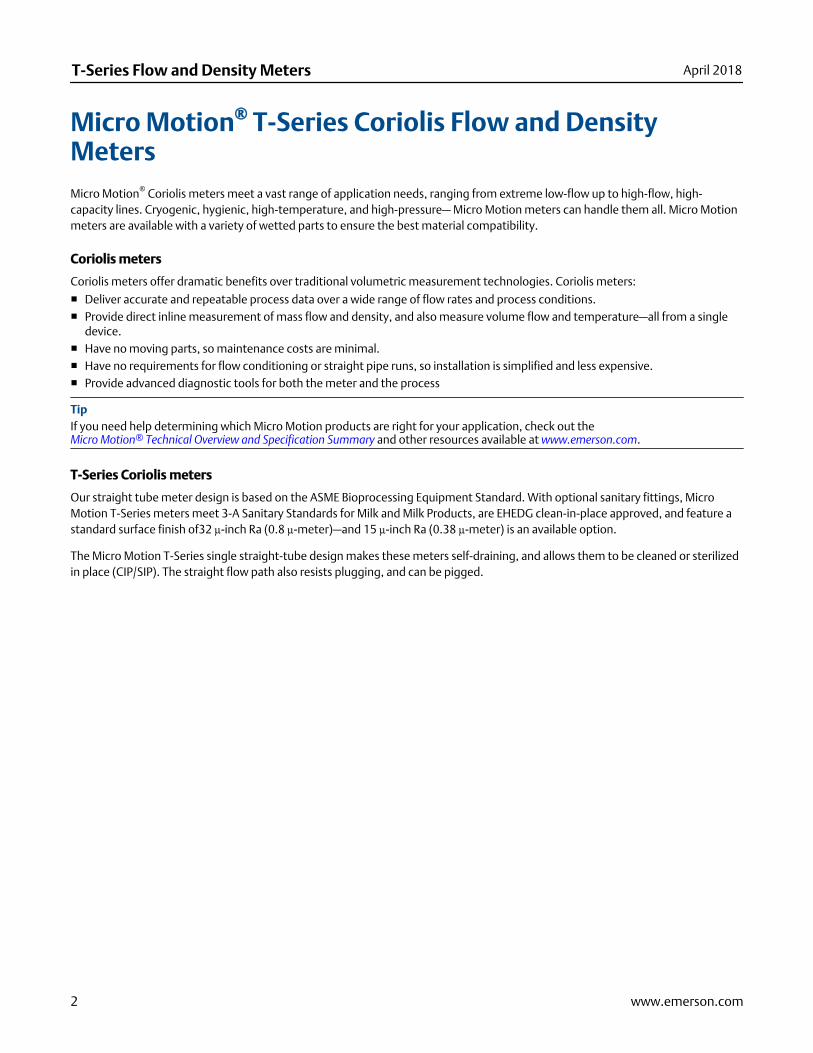
Mass flow measurementThe measuring tubes are forced to oscillate producing a sine wave. At zero flow, the two tubes vibrate in phase with each other.When flow is introduced, the Coriolis forces cause the tubes to twist resulting in a phase shift. The time difference between thewaves is measured and is directly proportional to the mass flow rate.
Flow Tube
Reference Tube
Case TransitionBracket
Pickoff Coil
Pickoff Coil
Drive Coil
Case TransitionBracket
Density measurementThe measuring tubes are vibrated at their natural frequency. A change in the mass of the fluid contained inside the tubes causes acorresponding change to the tube natural frequency. The frequency change of the tube is used to calculate density.
Temperature measurementTemperature is a measured variable that is available as an output. The temperature is also used internal to the sensor tocompensate for temperature influences on Young’s Modulus of Elasticity.
Meter characteristics■ Measurement accuracy is a function of fluid mass flow rate independent of operating temperature, pressure, or composition.
However, pressure drop through the sensor is dependent upon operating temperature, pressure, and fluid composition.
April 2018 T-Series Flow and Density Meters
www.emerson.com 3

■ Specifications and capabilities vary by model and certain models may have fewer available options. Please refer to the OnlineStore Sizing and Selection Tool at the Emerson web site (www.emerson.com) for detailed information regarding performance andcapabilities.
■ The letter at the end of the base model code (for example T100T) represents wetted part titanium material surface finish: T= 32Ra (0.8 µm); F = 15 Ra (0.38 µm). Detailed information about the complete product model codes are described later in thisdocument.
Performance specifications
Reference operating conditionsFor determining the performance capabilities of our meters, the following conditions were observed/utilized:
■ Water at 68 to 77 °F and 14.5 to 29 psig (20 to 25 °C and 1 to 2 barg)■ Air and Natural Gas at 68 to 77°F and 500 - 1450 psig (20 to 25 °C and 34 to 100 barg)■ Accuracy based on industry leading accredited calibration stands according to ISO 17025/IEC 17025■ All models have a density range up to 3 g/cm3 (3000 kg/m3)
Accuracy and repeatability
Accuracy and repeatability on liquids and slurries
Performance Specifications All models
Mass flow accuracy(1) ±0.15% of rate
Volume flow accuracy(1)(2) ±0.25% of rate
Mass flow repeatability 0.075% of rate
Volume flow repeatability 0.125% of rate
Density accuracy ±0.002 g/cm3 (±2.0 kg/m3 )
Density repeatability 0.0005 g/cm3 (0.5 kg/m3 )
Temperature accuracy ±1 °C ±0.5% of reading
Temperature repeatability 0.2 °C
(1) Stated flow accuracy includes the combined effects of repeatability, linearity, and hysteresis.
(2) At calibration conditions and fluid.
Accuracy and repeatability on gases
Performance specification All models
Mass flow accuracy(1) ±0.5% of rate
Mass flow repeatability(1) 0.25% of rate
Temperature accuracy ±1 °C ±0.5% of reading
T-Series Flow and Density Meters April 2018
4 www.emerson.com

Performance specification All models
Temperature repeatability 0.2 °C
(1) Stated flow accuracy includes the combined effects of repeatability, linearity, and hysteresis
Liquid flow rates
Nominal flow rate
Micro Motion has adopted the term nominal flow rate, which is the flow rate at which water at reference conditions causesapproximately 14.5 psig (1 barg) of pressure drop across the meter. For T-Series sensors, the nominal flow rate is also the maximumflow rate.
Mass flow rates for all models
Model
Nominal line size Nominal/maximum flow rate
inch mm lb/min kg/h
T025 1/4” DN6 25 680
T050 1/2” DN15 140 3,800
T075 3/4” DN20 500 14,000
T100 1” DN25 1,100 30,000
T150 1-1/2” DN40 3,200 87,000
Volume flow rates for all models
Model
Nominal/maximum flow rate
gal/min barrels/h l/h
T025 3 4.3 680
T050 17 24 3,800
T075 62 89 4,574
T100 132 189 30,000
T150 383 547 87,000
Gas flow ratesWhen selecting sensors for gas applications, pressure drop through the sensor is dependent upon operating temperature, pressure,and fluid composition. Therefore, when selecting a sensor for any particular gas application, it is highly recommended that eachsensor be sized using the Online Store Sizing and Selection Tool at the Emerson web site (www.emerson.com).
The below table indicates mass flow rates that produce approximately 10 psig (1.7 barg) pressure drop on natural gas withmolecular weight of 17 at 60 °F (16 °C) and 500 psig (34 barg).
April 2018 T-Series Flow and Density Meters
www.emerson.com 5

Gas flow rates for all models
Model
Mass Volume
lb/min kg/h SCFM Nm3 /h
T025 2.8 76 64 100
T050 20 540 460 780
T075 75 2,000 1,700 2,800
T100 160 4,300 3,700 6,300
T150 400 10,000 9,500 16,000
NoteStandard (SCFM) reference conditions for natural gas with molecular weight of 17 are 14.7 psig (1 barg) and 60 °F (15 °C).
Zero stabilityZero stability is used when the flow rate approaches the low end of the flow range where the meter accuracy begins to deviate fromthe stated accuracy rating, as depicted in the turndown section below. When operating at flow rates where meter accuracy beginsto deviate from the stated accuracy rating, accuracy is governed by the formula: accuracy = (zero stability/flow rate) x 100%.Repeatability is similarly affected by low flow conditions.
Turndown capabilities
The graph and table below represent an example of the measurement characteristics under various flow conditions. At flow ratesrequiring large turndowns (greater than 20:1), the zero stability values may begin to govern capability dependent upon flowconditions and meter in use.
A. Accuracy, %B. Flow rate, % of nominal
Turndown from nominal flow rate 100:1 20:1 10:1 1:1
Accuracy ±% 1.50 0.30 0.15 0.15
Pressure drop psig (barg) ~0 (0) 0.06(0.02) 0.22 (0.05) 14.3 (0.99)
T-Series Flow and Density Meters April 2018
6 www.emerson.com

Zero stability for all models
Model
Zero stability
lb/min kg/h
T025 0.0038 0.10
T050 0.021 0.57
T075 0.075 2.0
T100 0.165 4.50
T150 0.48 13.0
Process pressure ratingsSensor maximum working pressure reflects the highest possible pressure rating for a given sensor. Process connection type andenvironmental and process fluid temperatures may reduce the maximum rating. Refer to the Technical Data Sheet for commonsensor and fitting combinations.
All sensors comply with Council Directive 2014/68/EU on pressure equipment.
Sensor maximum working pressure for all models
Model psig barg
All T-Series sensors 1,450 100
Case pressure
Case pressure for all models
Model(1) psig barg
All T-Series sensors 1,450 100
All T-Series sensors with purge fittings 725 50
(1) One time case containment pressure over a period of a maximum of 10 hours.
Operating conditions: Environmental
Vibration limitsMeets IEC 68.2.6, endurance sweep, 5 to 2000 Hz, 50 sweep cycles at 1.0 g.
Temperature limitsSensors can be used in the process and ambient temperature ranges shown in the temperature limit graphs. For the purposes ofselecting electronics options, temperature limit graphs should be used only as a general guide. If your process conditions are closeto the gray area, consult with your Micro Motion representative.
April 2018 T-Series Flow and Density Meters
www.emerson.com 7

Note■ In all cases, the electronics cannot be operated where the ambient temperature is below –40 °F (–40 °C) or above +140 °F
(+60 °C). If a sensor is to be used where the ambient temperature is outside of the range permissible for the electronics, theelectronics must be remotely located where the ambient temperature is within the permissible range, as indicated by the shadedareas of the temperature limit graphs.
■ Temperature limits may be further restricted by hazardous area approvals. Refer to the hazardous area approvals documentationshipped with the sensor or available at www.emerson.com.
■ The extended-mount electronics option allows the sensor case to be insulated without covering the transmitter, core processor,or junction box, but does not affect temperature ratings. When insulating the sensor case at elevated process temperatures(above 140 °F), please ensure electronics are not enclosed in insulation as this may lead to electronics failure.
Ambient and process temperature limits for all models
125.5 (52)140 (60)
–40 (–40)
122 (50)
–60 (–51)–60
(–51)300
(149)
A
B
B
Tamb
Tproc
Operating conditions: Process
Process temperature effectFor mass flow measurement, process temperature effect is defined as the change in sensor flow accuracy due to processtemperature change away from the calibration temperature. Temperature effect can be corrected by zeroing at the processconditions.
Process temperature effect for all models
Model Mass flow rate (% of maximum rate) per °C
All T-Series sensors ±0.002
Process pressure effectProcess pressure effect is defined as the change in sensor flow and density accuracy due to process pressure change away from thecalibration pressure. This effect can be corrected by dynamic pressure input or a fixed meter factor. See installation manual forproper setup and configuration.
T-Series Flow and Density Meters April 2018
8 www.emerson.com

Process pressure effect for all models
Model code
Liquid or gas flow (% of rate) Density
per psig per barg g/cm3 per psig kg/m3 per barg
T025 none none 0.0000942 1.37
T050 none none 0.0000357 0.518
T075 none none 0.0000255 0.370
T100 none none 0.0000154 0.223
T150 none none 0.0000109 0.158
Hazardous area classificationsApprovals and certifications
Type Approval or certification (typical)
CSA and CSA C-US Ambient temperature: –40 to +140 °F (–40 to +60 °C) Class I, Div. 1, Groups C and D
Class I, Div. 2, Groups A, B, C, and D Class II, Div.1, Groups E, F, and G
ATEX II 2G Ex ib IIB/IIC T1–T4/T5/T6 Gb
II 2D Ex ib IIIC T* °C Db IP66
II 3G Ex nA IIC T1–T4/T5 Gc
II 3D Ex tc IIIC T*°C Dc IP66
IECEx Ex ib IIB/IIC T1–T4/T5/T6 Gb
Ex nA IIC T1-T4/T5 Gc
NEPSI Ex ib IIB/IIC T1–T6 Gb
Ex ibD 21 T450°C-T85°C Ex nA IIC T1–T6 Gc
DIP A22 T* T1-T6
Ingress Protection Rating IP 66 for sensors; IP66/IP67/IP69(K)(1) for transmitters
EMC effects Complies with EMC directive 2004/108/EC per EN 61326 Industrial
Complies with NAMUR NE-21 (09.05.2012)
(1) IP69(K) available on some transmitters. See transmitter PDS for details.
Note■ Approvals shown are for T-Series meters configured with a model 2700S transmitter. Meters with integral electronics may have
more restrictive approvals. Refer to the Product Data Sheet for each transmitter for details.■ When a meter is ordered with hazardous area approvals, detailed information is shipped along with the product.■ You can find more information about hazardous approvals, including detailed specifications and temperature graphs for all
meter configurations on the T-Series product page at the Emerson web site (www.emerson.com).
April 2018 T-Series Flow and Density Meters
www.emerson.com 9

Industry standards
Type Standard
Sanitary applications ■ ASME Bioprocessing Equipment Standard — 1997■ 3-A Sanitary Standards for Milk and Dairy Products■ EHEDG Machinery Directive 98/37/EC, annex 1, section 2.1
Industry standards and com-mercial approvals
■ NAMUR: NE132 (Burst pressure, sensor flange to flange length), NE131■ Pressure Equipment Directive (PED)■ Canadian Registration Number (CRN)■ Dual Seal■ ASME B31.1 power piping code and ASME B31.3 process piping code■ SIL2 and SIL3 safety certifications
NoteSome models do not meet all of the listed standards. Contact a sales representative for more information.
Transmitter interfaceA Micro Motion flowmeter system is highly customizable to provide a configuration that is tailor-fit to specific applications.
Robust transmitter offerings allow a multitude of mounting options:
■ Compact mounting integral to the sensor■ Field mount variants for harsh conditions■ Compact control room DIN rail packages for optimal locating in a control cabinet■ Specific fit-for-purpose solutions for two-wire connectivity or filling and dosing machinery integration
Micro Motion meters are available with an expansive selection of input and output connectivity options including the following:
■ 4-20 mA■ HART™
■ WirelessHART™
■ EtherNet/IP■ FOUNDATION™ fieldbus■ PROFIBUS■ Modbus®
■ Other protocols may be available on request
Physical specifications
Materials of constructionGeneral corrosion guidelines do not account for cyclical stress, and therefore should not be relied upon when choosing a wettedmaterial for your Micro Motion meter. Please refer to the Micro Motion Corrosion Guide for material compatibility information.
T-Series Flow and Density Meters April 2018
10 www.emerson.com

Flow tubes
Model
All models
Titanium ASTM Grade 9
Sensor weight(1)
lb kg
T025 ● 14 6
T050 ● 16 7
T075 ● 33 15
T100 ● 58 26
T150 ● 137 62
(1) Weight specifications are based upon ASME B16.5 CL150 flange and do not include electronics.
Process fittings
Type Material
Sanitary fittings(1) 304L stainless steel and titanium ASTM Grade 1
Socket-weld flanges(1) F316/316L stainless steel and titanium ASTM Grade 5 (6AL-4V)
(1) Flanges are stainless steel; wetted parts are titanium. Only titanium is in contact with process flow.
Non-wetted part materials
Component Enclosure rating 316L stainless steel 304L stainless steelPolyurethane-paintedaluminum
Sensor housing NEMA 4X (IP66) ●
Core processor housing NEMA 4X (IP66/67) ● ●
Junction box housing NEMA 4X (IP66/67) ● ●
Model 1700/2700transmitter housing
NEMA 4X (IP66/67) ● ●
Model 3700 transmitterhousing
NEMA 4X (IP66/67) ●
DimensionsThese dimensional drawings are intended to provide a basic guideline for sizing and planning. Face-to-Face (Dim. A, below)dimensions for all meters with each available process connection can be found in the product Technical Data Sheet. Complete anddetailed dimensional drawings can be found through the product link in our online store (www.emerson.com).
Note■ All dimensions ±1/8 inch (±3 mm).■ Models used for example dimensions:32 Ra (0.8 m) surface finishASME Class 150 flange Painted aluminum integral core
processor
April 2018 T-Series Flow and Density Meters
www.emerson.com 11

Example dimensions
B
C
A
Model Flange size
Dim. A Dim. B Dim. C
Inch mm Inch mm Inch mm
T025 1/2-inch 13-5/16 338 5-1/4 134 3-1/8 79
T050 1/2-inch 15-3/4 400 5-1/4 134 3-1/8 79
T075 1-inch 21-1/16 535 5-13/16 148 4-1/8 105
T100 1-inch 25-1/2 648 6-5/16 161 5-1/8 130
T150 1-1/2-inch 31-7/16 799 7-5/16 186 7-1/8 181
Ordering information
Model code structureA complete sensor model code includes the ordering options.
Example code Description
T075T Base model
628 Process connections
S Case options
Q Electronics interface
B Conduit connections
M Approvals
E Languages
Z Future option 1
Z Future option 2
Z Measurement application software
Z Factory options
T-Series Flow and Density Meters April 2018
12 www.emerson.com

Base model
Code Description
Standard sensor models
T025T Micro Motion Coriolis T-Series sensor; 1/4-inch; straight tube; titanium; 32 Ra (0.8 μm) surface finish
T050T Micro Motion Coriolis T-Series sensor; 1/2-inch; straight tube; titanium; 32 Ra (0.8 μm) surface finish
T075T Micro Motion Coriolis T-Series sensor; 3/4-inch; straight tube; titanium; 32 Ra (0.8 μm) surface finish
T100T Micro Motion Coriolis T-Series sensor; 1-inch; straight tube; titanium; 32 Ra (0.8 μm) surface finish
T150T Micro Motion Coriolis T-Series sensor; 1-1/2-inch; straight tube; titanium; 32 Ra (0.8 μm) surface finish
Improved surface sensor models
T025F Micro Motion Coriolis T-Series sensor; 1/4-inch; straight tube; titanium; 15 Ra (0.38 μm) surface finish
T050F Micro Motion Coriolis T-Series sensor; 1/2-inch; straight tube; titanium; 15 Ra (0.38 μm) surface finish
T075F Micro Motion Coriolis T-Series sensor; 3/4-inch; straight tube; titanium; 15 Ra (0.38 μm) surface finish
T100F Micro Motion Coriolis T-Series sensor; 1-inch; straight tube; titanium; 15 Ra (0.38 μm) surface finish
T150F Micro Motion Coriolis T-Series sensor; 1-1/2-inch; straight tube; titanium; 15 Ra (0.38 μm) surface finish
Process connections
Model T025T
Code Description
525 DN15 PN40 EN 1092-1 F316/F316L Weld neck flange Form B1
526 DN15 PN100 EN 1092-1 F316/F316L Weld neck flange Form B2
613 1/2-inch CL150 ASME B16.5 F316/F316L Socket weld flange Raised face
614 1/2-inch CL300 ASME B16.5 F316/F316L Socket weld flange Raised face
615 1/2-inch CL600 ASME B16.5 F316/F316L Socket weld flange Raised face
616 DN15 PN40 DIN 2526 F316/F316L Socket weld flange Type C face
617 DN15 PN100 DIN 2526 F316/F316L Socket weld flange Type E face
621 1/2-inch Tri-Clamp compati-ble
Ti grade 1 clad to304L backing
Hygienic fitting
636 #8 VCO Ti grade 1 clad to304L backing
Swagelok compatiblefitting
316/316L1/2-inchNPT female adapter
637 #8 VCO Ti grade 1 clad to304L backing
Swagelok compatiblefitting
650 DN15 PN40 DIN 2512 F316/F316L Socket weld flange Type N grooved face
654 DN15 PN40 EN 1092-1 F316/F316L Weld neck flange Form D
670 DN10 DIN11851 Ti grade 1 clad to304L backing
Hygienic coupling
671 DN15 DIN11851 Ti grade 1 clad to304L backing
Hygienic coupling
676 DN15 DIN11864-1A Ti grade 1 clad to304L backing
Hygienic coupling
April 2018 T-Series Flow and Density Meters
www.emerson.com 13

Code Description
781 15mm 20K JIS B 2220 F316/F316L Socket weld flange
Model T025F
Code Description
621 1/2-inch Tri-Clamp compati-ble
Ti grade 1 clad to304L backing
Hygienic fitting
670 DN10 DIN11851 Ti grade 1 clad to304L backing
Hygienic coupling
671 DN15 DIN11851 Ti grade 1 clad to304L backing
Hygienic coupling
676 DN15 DIN11864-1A Ti grade 1 clad to304L backing
Hygienic coupling
Model T050T
Code Description
525 DN15 PN40 EN 1092-1 F316/F316L Weld neck flange Form B1
526 DN15 PN100 EN 1092-1 F316/F316L Weld neck flange Form B2
613 1/2-inch CL150 ASME B16.5 F316/F316L Socket weld flange Raised face
614 1/2-inch CL300 ASME B16.5 F316/F316L Socket weld flange Raised face
615 1/2-inch CL600 ASME B16.5 F316/F316L Socket weld flange Raised face
616 DN15 PN40 DIN 2526 F316/F316L Socket weld flange Type C face
617 DN15 PN100 DIN 2526 F316/F316L Socket weld flange Type E face
621 1/2-inch Tri-Clamp compati-ble
Ti grade 1 clad to304L backing
Hygienic fitting
638 #12 VCO Ti grade 1 clad to304L backing
Swagelok compatiblefitting
316/316L3/4-inchNPT female adapter
639 #12 VCO Ti grade 1 clad to304L backing
Swagelok compatiblefitting
650 DN15 PN40 DIN 2512 F316/F316L Socket weld flange Type N grooved face
654 DN15 PN40 EN 1092-1 F316/F316L Weld neck flange Form D
671 DN15 DIN11851 Ti grade 1 clad to304L backing
Hygienic coupling
676 DN15 DIN11864-1A Ti grade 1 clad to304L backing
Hygienic coupling
781 15mm 20K JIS B 2220 F316/F316L Socket weld flange
Model T050F
Code Description
621 1/2-inch Tri-Clamp compati-ble
Ti grade 1 clad to304L backing
Hygienic fitting
671 DN15 DIN11851 Ti grade 1 clad to304L backing
Hygienic coupling
T-Series Flow and Density Meters April 2018
14 www.emerson.com

Code Description
676 DN15 DIN11864-1A Ti grade 1 clad to304L backing
Hygienic coupling
Model T075T
Code Description
525 DN15 PN40 EN 1092-1 F316/F316L Weld neck flange Form B1
526 DN15 PN100 EN 1092-1 F316/F316L Weld neck flange Form B2
527 DN25 PN40 EN 1092-1 F316/F316L Weld neck flange Form B1
528 DN25 PN100 EN 1092-1 F316/F316L Weld neck flange Form B2
613 1/2-inch CL150 ASME B16.5 F316/F316L Socket weld flange Raised face
614 1/2-inch CL300 ASME B16.5 F316/F316L Socket weld flange Raised face
615 1/2-inch CL600 ASME B16.5 F316/F316L Socket weld flange Raised face
616 DN15 PN40 DIN 2526 F316/F316L Socket weld flange Type C face
617 DN15 PN100 DIN 2526 F316/F316L Socket weld flange Type E face
618 DN25 PN40 DIN 2526 F316/F316L Socket weld flange Type C face
619 DN25 PN100 DIN 2526 F316/F316L Socket weld flange Type E face
622 3/4-inch Tri-Clamp compati-ble
Ti grade 1 clad to304L backing
Hygienic fitting
623 1-inch Tri-Clamp compati-ble
Ti grade 1 clad to304L backing
Hygienic fitting
628 1-inch CL150 ASME B16.5 F316/F316L Socket weld flange Raised face
629 1-inch CL300 ASME B16.5 F316/F316L Socket weld flange Raised face
630 1-inch CL600 ASME B16.5 F316/F316L Socket weld flange Raised face
650 DN15 PN40 DIN 2512 F316/F316L Socket weld flange Type N grooved face
651 DN25 PN40 DIN 2512 F316/F316L Socket weld flange Type N grooved face
654 DN15 PN40 EN 1092-1 F316/F316L Weld neck flange Form D
655 DN25 PN40 EN 1092-1 F316/F316L Weld neck flange Form D
662 DN25 ISO 2853 (IDF) Ti grade 1 clad to304L backing
Hygienic coupling
672 DN25 DIN11851 Ti grade 1 clad to304L backing
Hygienic coupling
677 DN25 DIN11864-1A Ti grade 1 clad to304L backing
Hygienic coupling
692 DN25 SMS 1145 Ti grade 1 clad to304L backing
Hygienic coupling
781 15mm 20K JIS B 2220 F316/F316L Socket weld flange
782 25mm 20K JIS B 2220 F316/F316L Socket weld flange
Model T075F
Code Description
613 1/2-inch CL150 ASME B16.5 F316/F316L Socket weld flange Raised face
April 2018 T-Series Flow and Density Meters
www.emerson.com 15

Code Description
614 1/2-inch CL300 ASME B16.5 F316/F316L Socket weld flange Raised face
615 1/2-inch CL600 ASME B16.5 F316/F316L Socket weld flange Raised face
616 DN15 PN40 DIN 2526 F316/F316L Socket weld flange Type C face
617 DN15 PN100 DIN 2526 F316/F316L Socket weld flange Type E face
618 DN25 PN40 DIN 2526 F316/F316L Socket weld flange Type C face
619 DN25 PN100 DIN 2526 F316/F316L Socket weld flange Type E face
622 3/4-inch Tri-Clamp compati-ble
Ti grade 1 clad to304L backing
Hygienic fitting
623 1-inch Tri-Clamp compati-ble
Ti grade 1 clad to304L backing
Hygienic fitting
628 1-inch CL150 ASME B16.5 F316/F316L Socket weld flange Raised face
629 1-inch CL300 ASME B16.5 F316/F316L Socket weld flange Raised face
630 1-inch CL600 ASME B16.5 F316/F316L Socket weld flange Raised face
650 DN15 PN40 DIN 2512 F316/F316L Socket weld flange Type N grooved face
651 DN25 PN40 DIN 2512 F316/F316L Socket weld flange Type N grooved face
662 DN25 ISO 2853 (IDF) Ti grade 1 clad to304L backing
Hygienic coupling
672 DN25 DIN11851 Ti grade 1 clad to304L backing
Hygienic coupling
677 DN25 DIN11864-1A Ti grade 1 clad to304L backing
Hygienic coupling
692 DN25 SMS 1145 Ti grade 1 clad to304L backing
Hygienic coupling
781 15mm 20K JIS B 2220 F316/F316L Socket weld flange
782 25mm 20K JIS B 2220 F316/F316L Socket weld flange
Model T100T
Code Description
527 DN25 PN40 EN 1092-1 F316/F316L Weld neck flange Form B1
528 DN25 PN100 EN 1092-1 F316/F316L Weld neck flange Form B2
618 DN25 PN40 DIN 2526 F316/F316L Socket weld flange Type C face
619 DN25 PN100 DIN 2526 F316/F316L Socket weld flange Type E face
623 1-inch Tri-Clamp compati-ble
Ti grade 1 clad to304L backing
Hygienic fitting
624 1-1/2-inch
Tri-Clamp compati-ble
Ti grade 1 clad to304L backing
Hygienic fitting
628 1-inch CL150 ASME B16.5 F316/F316L Socket weld flange Raised face
629 1-inch CL300 ASME B16.5 F316/F316L Socket weld flange Raised face
630 1-inch CL600 ASME B16.5 F316/F316L Socket weld flange Raised face
641 1-1/2-inch
CL150 ASME B16.5 F316/F316L Socket weld flange Raised face
T-Series Flow and Density Meters April 2018
16 www.emerson.com

Code Description
642 1-1/2-inch
CL300 ASME B16.5 F316/F316L Socket weld flange Raised face
643 1-1/2-inch
CL600 ASME B16.5 F316/F316L Socket weld flange Raised face
651 DN25 PN40 DIN 2512 F316/F316L Socket weld flange Type N grooved face
652 DN40 PN40 DIN 2512 F316/F316L Socket weld flange Type N grooved face
655 DN25 PN40 EN 1092-1 F316/F316L Weld neck flange Form D
656 DN40 PN40 EN 1092-1 F316/F316L Weld neck flange Form D
658 DN40 PN40 EN 1092-1 F316/F316L Weld neck flange Form B1
659 DN40 PN100 EN 1092-1 F316/F316L Weld neck flange Form B2
672 DN25 DIN11851 Ti grade 1 clad to304L backing
Hygienic coupling
677 DN25 DIN11864-1A Ti grade 1 clad to304L backing
Hygienic coupling
681 DN40 PN40 DIN 2526 F316/F316L Socket weld flange Type C face
682 DN40 PN100 DIN 2526 F316/F316L Socket weld flange Type E face
782 25mm 20K JIS B 2220 F316/F316L Socket weld flange
783 40mm 20K JIS B 2220 F316/F316L Socket weld flange
Model T100F
Code Description
618 DN25 PN40 DIN 2526 F316/F316L Socket weld flange Type C face
619 DN25 PN100 DIN 2526 F316/F316L Socket weld flange Type E face
623 1-inch Tri-Clamp compati-ble
Ti grade 1 clad to304L backing
Hygienic fitting
624 1-1/2-inch
Tri-Clamp compati-ble
Ti grade 1 clad to304L backing
Hygienic fitting
628 1-inch CL150 ASME B16.5 F316/F316L Socket weld flange Raised face
629 1-inch CL300 ASME B16.5 F316/F316L Socket weld flange Raised face
630 1-inch CL600 ASME B16.5 F316/F316L Socket weld flange Raised face
641 1-1/2-inch
CL150 ASME B16.5 F316/F316L Socket weld flange Raised face
642 1-1/2-inch
CL300 ASME B16.5 F316/F316L Socket weld flange Raised face
651 DN25 PN40 DIN 2512 F316/F316L Socket weld flange Type N grooved face
652 DN40 PN40 DIN 2512 F316/F316L Socket weld flange Type N grooved face
672 DN25 DIN11851 Ti grade 1 clad to304L backing
Hygienic coupling
677 DN25 DIN11864-1A Ti grade 1 clad to304L backing
Hygienic coupling
681 DN40 PN40 DIN 2526 F316/F316L Socket weld flange Type C face
682 DN40 PN100 DIN 2526 F316/F316L Socket weld flange Type E face
April 2018 T-Series Flow and Density Meters
www.emerson.com 17

Code Description
782 25mm 20K JIS B 2220 F316/F316L Socket weld flange
783 40mm 20K JIS B 2220 F316/F316L Socket weld flange
Model T150T
Code Description
624 1-1/2-inch
Tri-Clamp compati-ble
Ti grade 1 clad to304L backing
Hygienic fitting
625 2-inch Tri-Clamp compati-ble
Ti grade 1 clad to304L backing
Hygienic fitting
641 1-1/2-inch
CL150 ASME B16.5 F316/F316L Socket weld flange Raised face
642 1-1/2-inch
CL300 ASME B16.5 F316/F316L Socket weld flange Raised face
643 1-1/2-inch
CL600 ASME B16.5 F316/F316L Socket weld flange Raised face
644 2-inch CL150 ASME B16.5 F316/F316L Socket weld flange Raised face
645 2-inch CL300 ASME B16.5 F316/F316L Socket weld flange Raised face
646 2-inch CL600 ASME B16.5 F316/F316L Socket weld flange Raised face
652 DN40 PN40 DIN 2512 F316/F316L Socket weld flange Type N grooved face
653 DN50 PN40 DIN 2512 F316/F316L Socket weld flange Type N grooved face
656 DN40 PN40 EN 1092-1 F316/F316L Weld neck flange Form D
657 DN50 PN40 EN 1092-1 F316/F316L Weld neck flange Form D
658 DN40 PN40 EN 1092-1 F316/F316L Weld neck flange Form B1
659 DN40 PN100 EN 1092-1 F316/F316L Weld neck flange Form B2
660 DN50 PN40 EN 1092-1 F316/F316L Weld neck flange Form B1
661 DN50 PN100 EN 1092-1 F316/F316L Weld neck flange Form B2
663 DN51 ISO 2853 (IDF) Ti grade 1 clad to304L backing
Hygienic coupling
673 DN40 DIN11851 Ti grade 1 clad to304L backing
Hygienic coupling
674 DN50 DIN11851 Ti grade 1 clad to304L backing
Hygienic coupling
678 DN50 DIN11864-1A Ti grade 1 clad to304L backing
Hygienic coupling
681 DN40 PN40 DIN 2526 F316/F316L Socket weld flange Type C face
682 DN40 PN100 DIN 2526 F316/F316L Socket weld flange Type E face
683 DN50 PN40 DIN 2526 F316/F316L Socket weld flange Type C face
684 DN50 PN100 DIN 2526 F316/F316L Socket weld flange Type E face
693 DN51 SMS 1145 Ti grade 1 clad to304L backing
Hygienic coupling
783 40mm 20K JIS B 2220 F316/F316L Socket weld flange
T-Series Flow and Density Meters April 2018
18 www.emerson.com

Code Description
784 50mm 20K JIS B 2220 F316/F316L Socket weld flange
Model T150F
Code Description
624 1-1/2-inch
Tri-Clamp compati-ble
Ti grade 1 clad to304L backing
Hygienic fitting
625 2-inch Tri-Clamp compati-ble
Ti grade 1 clad to304L backing
Hygienic fitting
641 1-1/2-inch
CL150 ASME B16.5 F316/F316L Socket weld flange Raised face
642 1-1/2-inch
CL300 ASME B16.5 F316/F316L Socket weld flange Raised face
643 1-1/2-inch
CL600 ASME B16.5 F316/F316L Socket weld flange Raised face
644 2-inch CL150 ASME B16.5 F316/F316L Socket weld flange Raised face
645 2-inch CL300 ASME B16.5 F316/F316L Socket weld flange Raised face
646 2-inch CL600 ASME B16.5 F316/F316L Socket weld flange Raised face
652 DN40 PN40 DIN 2512 F316/F316L Socket weld flange Type N grooved face
653 DN50 PN40 DIN 2512 F316/F316L Socket weld flange Type N grooved face
663 DN51 ISO 2853 (IDF) Ti grade 1 clad to304L backing
Hygienic coupling
673 DN40 DIN11851 Ti grade 1 clad to304L backing
Hygienic coupling
674 DN50 DIN11851 Ti grade 1 clad to304L backing
Hygienic coupling
678 DN50 DIN11864-1A Ti grade 1 clad to304L backing
Hygienic coupling
681 DN40 PN40 DIN 2526 F316/F316L Socket weld flange Type C face
682 DN40 PN100 DIN 2526 F316/F316L Socket weld flange Type E face
683 DN50 PN40 DIN 2526 F316/F316L Socket weld flange Type C face
684 DN50 PN100 DIN 2526 F316/F316L Socket weld flange Type E face
693 DN51 SMS 1145 Ti grade 1 clad to304L backing
Hygienic coupling
783 40mm 20K JIS B 2220 F316/F316L Socket weld flange
784 50mm 20K JIS B 2220 F316/F316L Socket weld flange
Case options
Code Case option
S 1,450 psig (100 bar) containment
April 2018 T-Series Flow and Density Meters
www.emerson.com 19

Code Case option
P Purge fittings (two 1/2-inch NPT female); 725 psig (50 bar) containment; not available with sensors with improvedsurface finish option
Electronics interface
Code Electronics interface
Q 4-wire polyurethane-painted aluminum integral core processor for remotely mounted transmitter with MVD Tech-nology
A 4-wire stainless steel integral core processor for remotely mounted transmitter with MVD Technology
V 4-wire polyurethane-painted aluminum integral core processor with extended mount for remotely mounted trans-mitter with MVD Technology
B 4-wire stainless steel integral core processor with extended mount for remotely mounted transmitter with MVDTechnology
C Integrally mounted Model 1700 or 2700 transmitter
W(1) MVDSolo; polyurethane-painted aluminum integral core processor for direct host connection (for OEMs)
D(1) MVDSolo; stainless steel integral core processor for direct host connection (for OEMs)
Y(1) MVDSolo; extended mount polyurethane-painted aluminum integral core processor (for OEMs)
E(1) MVDSolo, extended mount stainless steel integral core processor (for OEMs)
R 9-wire polyurethane-painted junction box; not available with Models T025 or T050
H 9-wire polyurethane-painted junction box with extended mount; not available with Models T025 or T050
(1) When electronics interface W, D, Y or E is ordered with approval U, C, A, Z , I, G with country specific approval R1, B1 MVD Direct Connect™ I.S.barrier is supplied.
Conduit connections
Code Conduit connection
Available with electronics interface codes
Q, A, V, B W, D, Y, E R, H C
B(1) 1/2-inch NPT; no gland ● ●
E(2) M20; no gland ● ●
F(1) Brass/nickel cable gland; cable diameter 0.335 to 0.394 inches(8.5 to 10 mm)
● ●
G(1) Stainless steel cable gland; cable diameter 0.335 to 0.394 in-ches (8.5 to 10 mm)
● ●
K(3) JIS B0202 1/2G; no gland ●
L(3) Japan - brass nickel cable gland ●
M(3) Japan - stainless cable gland ●
A 3/4-inch NPT; no gland ●
A No gland ●
H(1) 3/4-inch NPT with brass/nickel cable gland ●
J(1) 3/4-inch NPT; stainless steel cable gland ●
N(3) JIS B0202 3/4G - no gland ●
T-Series Flow and Density Meters April 2018
20 www.emerson.com

Code Conduit connection
Available with electronics interface codes
Q, A, V, B W, D, Y, E R, H C
O(3) Japan - brass nickel cable gland ●
P(3) Japan - stainless cable gland ●(1) Not available with approval code T or J.
(2) Not available with Electronics Interface Q, A, V, B in combination with Approval T.
(3) Only available with approval codes M or T.
Approvals
Code Case option
Available with electronics interface codes
Q, A, V, B, R, H W, D, Y, E(1) C
M Micro Motion Standard; no approval, without CE/EAC markings ● ● ●
N Micro Motion Standard / PED compliant; with CE/EAC markings ● ● ●
U UL ● ● ●
C CSA (Canada only) ● ● ●
A CSA (US and Canada): Class I, Division 1, Groups C and D ● ● ●
Z ATEX - Equipment Category 2 (Zone 1) / PED compliant ● ● ●
I IECEx Zone 1 ● ● ●
T TIIS - T4 Temperature Classification; not available for quote out-side Japan
● ●
J(2) Hardware ready for TIIS approval; EPM Japan only ● ●
V ATEX (Zone 2) / PED compliant ●
3 IECEx (Zone 2) ●
2 CSA (US and Canada): Class I, Division 2, Groups A, B, C, D ●
G Country Specific Approval – Requires a selection from the Ap-provals section of the ‘Certificate, Tests, Calibrations and Serv-ices’ model code option
● ● ●
(1) When electronics interface W, D, Y or E is ordered with approval U, C, A, Z , I, G with country specific approval R1, B1 MVD Direct Connect™ I.S.barrier is supplied.
(2) Not available with Approval code T or J.
Languages
Code Language option
A Danish CE requirements document and English installation manual
C(1) Czech installation manual
D Dutch CE requirements document and English installation manual
E English installation manual
F French installation manual
G German installation manual
H Finnish CE requirements document and English installation manual
April 2018 T-Series Flow and Density Meters
www.emerson.com 21
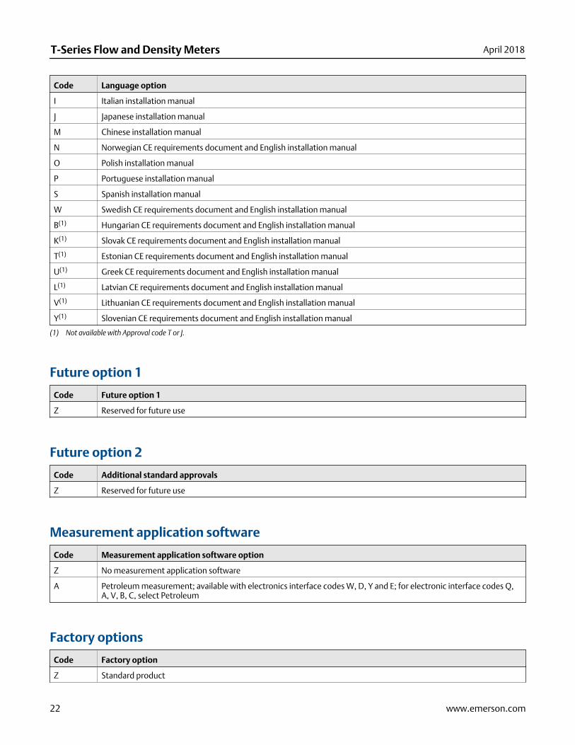
Code Language option
I Italian installation manual
J Japanese installation manual
M Chinese installation manual
N Norwegian CE requirements document and English installation manual
O Polish installation manual
P Portuguese installation manual
S Spanish installation manual
W Swedish CE requirements document and English installation manual
B(1) Hungarian CE requirements document and English installation manual
K(1) Slovak CE requirements document and English installation manual
T(1) Estonian CE requirements document and English installation manual
U(1) Greek CE requirements document and English installation manual
L(1) Latvian CE requirements document and English installation manual
V(1) Lithuanian CE requirements document and English installation manual
Y(1) Slovenian CE requirements document and English installation manual
(1) Not available with Approval code T or J.
Future option 1
Code Future option 1
Z Reserved for future use
Future option 2
Code Additional standard approvals
Z Reserved for future use
Measurement application software
Code Measurement application software option
Z No measurement application software
A Petroleum measurement; available with electronics interface codes W, D, Y and E; for electronic interface codes Q,A, V, B, C, select Petroleum
Factory options
Code Factory option
Z Standard product
T-Series Flow and Density Meters April 2018
22 www.emerson.com

Code Factory option
X ETO product
R Restocked product (if available)
Certificates, tests, calibrations, and servicesThese option codes can be added to the end of the model code if needed, but no code is required when none of these options isselected.
NoteThere may be additional options or limitations depending on total meter configuration. Contact a sales representative beforemaking your final selections.
Material quality examination tests and certificates
Code Factory option
MC Material inspection certificate 3.1 (supplier lot traceability per EN 10204)
Pressure testing
Select any from this group.
Code Factory option
HT Hydrostatic test certificate 3.1 (wetted components only)
PN Pneumatic test certificate 3.1
Dye penetrant examination
Select any from this group.
Code Factory option
D1 Dye penetrant test package 3.1; process connection only; liquid dye penetration NDE qualification
D2 Dye penetrant test package 3.1; case only; liquid dye penetration NDE qualification
Weld examination
Code Factory option
WP Weld procedure package (weld map, weld procedure specification, weld procedure qualification record, welder per-formance qualification)
Special cleaning
Code Factory option
O2 Declaration of compliance oxygen service 2.1
April 2018 T-Series Flow and Density Meters
www.emerson.com 23

GOST compliance
Code Factory option
GR Russian GOST calibration verification certificate
Accredited Calibration
Code Factory option
IC ISO17025 accredited calibration and certificates (9 points total)
Special calibration options
Select either none, CV, or CV with one of the additional verification point options.
NoteMinimum flow rates may apply when selecting the special calibration option.
Code Factory option
CV Custom verification (alter original verification points)
01 Add 1 additional verification point
02 Add 2 additional verification point
03 Add 3 additional verification point
06 Add up to 6 additional verification points
08 Add up to 8 additional verification points
16 Add up to 16 additional verification points
Sensor completion
Select any from this group.
Code Factory option
WG Witness general
SP Special packaging
Country specific approvals
Select one from the following if approval code G is selected.
Code Factory option
R1 EAC Zone 1 – Hazardous Approval
B1 INMETRO Zone 1 – Hazardous Approval
T-Series Flow and Density Meters April 2018
24 www.emerson.com

April 2018 T-Series Flow and Density Meters
www.emerson.com 25

T-Series Flow and Density Meters April 2018
26 www.emerson.com

April 2018 T-Series Flow and Density Meters
www.emerson.com 27

T-Series Flow and Density MetersPS-00371, Rev K
Product Data SheetApril 2018
Emerson Automation SolutionsWorldwide Headquarters7070 Winchester CircleBoulder, Colorado USA 80301T: +1 800-522-6277T: +1 303-527-5200F: +1 303-530-8459Mexico: 52 55 5809 5300Argentina: 54 11 4837 7000Brazil: 55 15 3413 8147Chile: 56 2 2928 4800
Emerson Automation SolutionsCentral Europe: +41 41 7686 111Eastern Europe: +41 41 7686 111Dubai: +971 4 811 8100Abu Dhabi: +971 2 697 2000France: 0800 917 901Germany: +49 (0) 2173 3348 0Italy: 8008 77334The Netherlands: +31 (0) 70 413 6666Belgium: +32 2 716 77 11Spain: +34 913 586 000U.K.: 0870 240 1978Russian/CIS: +7 495 981 9811
Emerson Automation SolutionsAustralia: (61) 3 9721 0200China: (86) 21 2892 9000India: (91) 22 6662 0566Japan: (81) 3 5769 6803South Korea: (82) 31 8034 0000Singapore: (65) 6 777 8211
©2018 Micro Motion, Inc. All rights reserved.
The Emerson logo is a trademark and service mark of Emerson Electric Co. Micro Motion, ELITE,ProLink, MVD and MVD Direct Connect marks are marks of one of the Emerson AutomationSolutions family of companies. All other marks are property of their respective owners.