Embed Size (px)
Citation preview
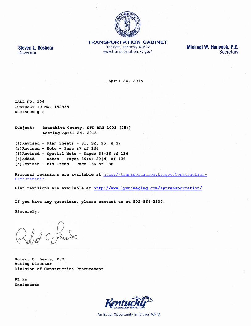
April 20, 2015
CALL NO. 106
CONTRACT ID NO. 152955
ADDENDUM # 2
Subject: Breathitt County, STP BRH 1003 (254)
Letting April 24, 2015
(1)Revised – Plan Sheets – S1, S2, S5, & S7
(2)Revised – Note – Page 27 of 136
(3)Revised – Special Note – Pages 34-36 of 136
(4)Added – Notes – Pages 39(a)-39(d) of 136(5)Revised – Bid Items – Page 136 of 136
Proposal revisions are available at http://transportation.ky.gov/Construction-
Procurement/.
Plan revisions are available at http://www.lynnimaging.com/kytransportation/.
If you have any questions, please contact us at 502-564-3500.
Sincerely,
Robert C. Lewis, P.E.
Acting Director
Division of Construction Procurement
RL:ks
Enclosures
CO
NS
TR
UC
TIO
N
PR
OJ
EC
T
NO.
LE
TTIN
G
DA
TE TRANSPORTATION CABINET
DEPARTMENT OF HIGHWAYS
INDEX OF SHEETSSheet No. Description
S1
S2
Title Sheet & General Notes
S4
Surface Preparation and Paint Application
Waste Management
Recyclable Surface Preparation Residue Manangement
Quality Control
Paint
Environmental and Worker Safety Regulations
Stenciling
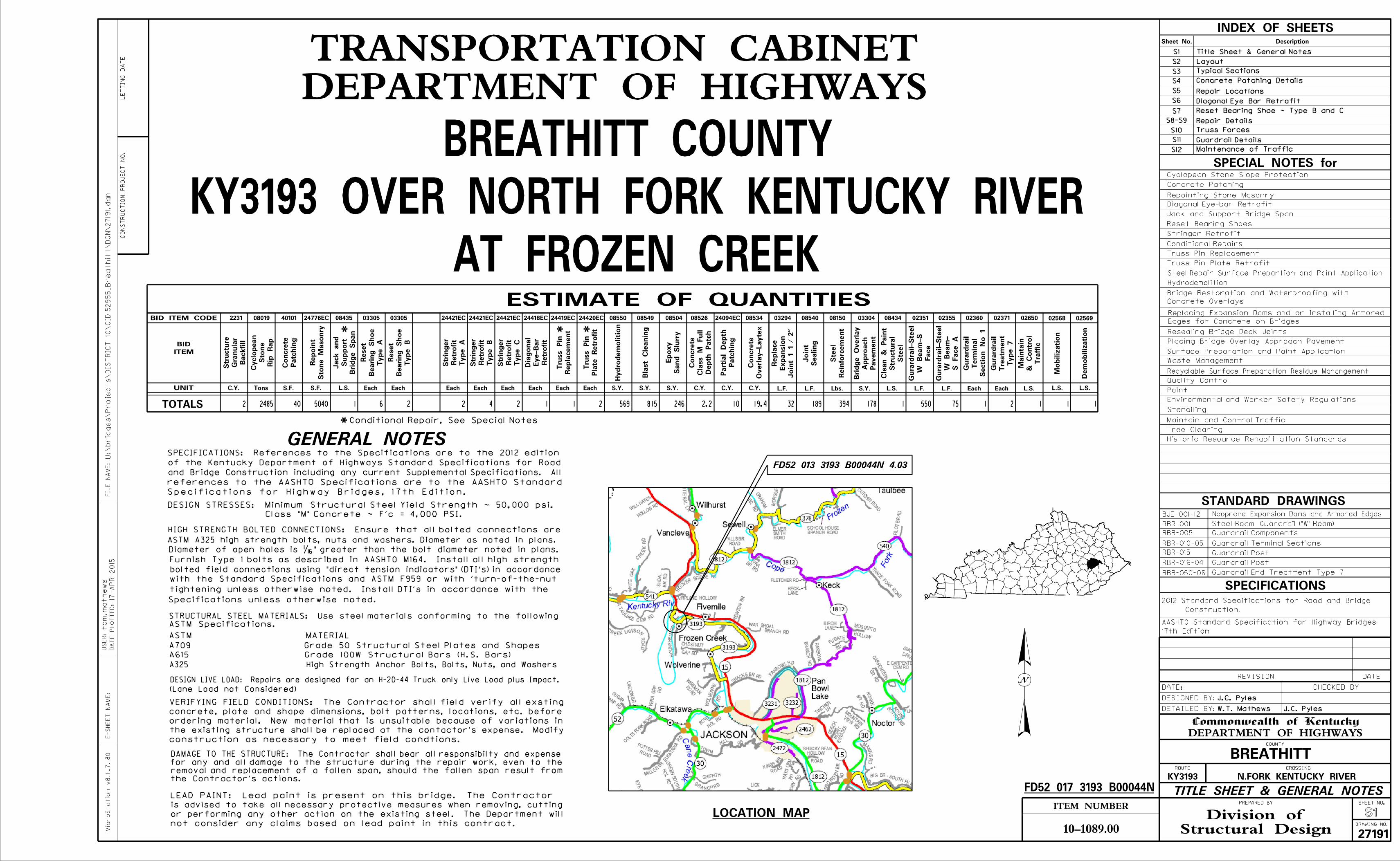
of the Kentucky Department of Highways Standard Specifications for Road
and Bridge Construction including any current Supplemental Specifications. All
STRUCTURAL STEEL MATERIALS: Use steel materials conforming to the following
ASTM Specifications.
ASTM MATERIAL
DAMAGE TO THE STRUCTURE: The Contractor shall bear all responsibilty and expense
removal and replacement of a fallen span, should the fallen span result from
DESIGN STRESSES: Minimum Structural Steel Yield Strength ~ 50,000 psi.
Furnish Type 1 bolts as described in AASHTO M164. Install all high strength
the Contractor’s actions.
for any and all damage to the structure during the repair work, even to the
construction as necessary to meet field condtions.
concrete, plate and shape dimensions, bolt patterns, locations, etc. before
ordering material. New material that is unsuitable because of variations in
the existing structure shall be replaced at the contactor’s expense. Modify
not consider any claims based on lead paint in this contract.
GENERAL NOTES
SPECIAL NOTES for
Diameter of open holes is �" greater than the bolt diameter noted in plans.
LEAD PAINT: Lead paint is present on this bridge. The Contractor
SPECIFICATIONS: References to the Specifications are to the 2012 edition
Specifications for Highway Bridges, 17th Edition.
tightening unless otherwise noted. Install DTI’s in accordance with the
with the Standard Specifications and ASTM F959 or with ’turn-of-the-nut
Specifications unless otherwise noted.
ASTM A325 high strength bolts, nuts and washers. Diameter as noted in plans.
Structural DesignDivision of
E-S
HE
ET
NA
ME:
Micro
Statio
n v8.11.7.18
0
ITEM NUMBER
DRAWING NO.
SHEET NO.
Commonwealth of Kentucky
DEPARTMENT OF HIGHWAYSCOUNTY
ROUTE CROSSING
PREPARED BY
DETAILED BY:
DESIGNED BY:
DATE: CHECKED BY
REVISION DATE
10-1089.00
J.C. Pyles
W.T. Mathews J.C. Pyles
BREATHITT
KY3193 N.FORK KENTUCKY RIVER
TITLE SHEET & GENERAL NOTES
S1
27191
17-
AP
R-2015
U:\brid
ges\
Projects\
DIS
TRIC
T 10\
CID15
2955_
Breathitt\
DG
N\2719
1.dgn
FIL
E
NA
ME:
DA
TE P
LO
TT
ED:
US
ER:to
m.
mathe
ws
A709 Grade 50 Structural Steel Plates and Shapes
Concrete Patching Details
AT FROZEN CREEK
KY3193 OVER NORTH FORK KENTUCKY RIVER
BREATHITT COUNTY
HIGH STRENGTH BOLTED CONNECTIONS: Ensure that all bolted connections are
bolted field connections using "direct tension indicators" (DTI’s) in accordance
A325 High Strength Anchor Bolts, Bolts, Nuts, and Washers
references to the AASHTO Specifications are to the AASHTO Standard
VERIFYING FIELD CONDITIONS: The Contractor shall field verify all exsting
is advised to take all necessary protective measures when removing, cutting
or performing any other action on the existing steel. The Department will
Edges for Concrete on Bridges
Replacing Expansion Dams and or Installing Armored
Concrete Overlays
Bridge Restoration and Waterproofing with
Repair DetailsS8-S9
Truss Forces
S11 Guardrail Details
S12 Maintenance of Traffic
LOCATION MAP
N
FD52 013 3193 B00044N 4.03
STANDARD DRAWINGS
RBR-001
RBR-005
RBR-010-05
RBR-015
RBR-016-04
RBR-050-06
Steel Beam Guardrail ("W" Beam)
Guardrail Components
Guardrail Terminal Sections
Guardrail Post
Guardrail Post
Guardrail End Treatment Type 7
SPECIFICATIONS
Construction.
2012 Standard Specifications for Road and Bridge
FD52 017 3193 B00044N
Concrete Patching
Steel Repair Surface Prepartion and Paint Application
Placing Bridge Overlay Approach Pavement
Maintain and Control Traffic
Class "M" Concrete ~ F’c = 4,000 PSI.
(Lane Load not Considered)
Repointing Stone Masonry
Jack and Support Bridge Span
S6 Diagonal Eye Bar Retrofit
S10
S3
S5 Repair Locations
Typical Sections
Stringer Retrofit
Conditional Repairs
Cyclopean Stone Slope Protection
Reset Bearing Shoes
Tree Clearing
17th Edition
AASHTO Standard Specification for Highway Bridges
Hydrodemolition
Resealing Bridge Deck Joints
Diagonal Eye-bar Retrofit
S7 Reset Bearing Shoe ~ Type B and C
BJE-001-12 Neoprene Expansion Dams and Armored Edges
Layout
Historic Resource Rehabilitation Standards
A615 Grade 100W Structural Bars (H.S. Bars)
DESIGN LIVE LOAD: Repairs are designed for an H-20-44 Truck only Live Load plus Impact.
Truss Pin Replacement
Truss Pin Plate Retrofit
UNIT
ITEM
BID
ESTIMATE OF QUANTITIES
08434
L.S.
1 1 1
02568
Ste
el
Str
uctural
Clean
& Paint
L.S.
Mobilization
L.S.
02569
De
mobilization
1
L.S.
Traffic
&
Contr
ol
Maintain
02650 24418EC
1
Retr
ofit
Eye-Bar
Dia
gonal
Each
1 2
Replace
ment
Truss Pin
Plate
Retr
ofit
Truss Pin
Each Each
24420EC 24419EC
6
Each
03305
Type
A
Bearing Shoe
Reset
2
Each
03305
Type
B
Bearing Shoe
Reset
2
Each
24421EC
Type
A
Retr
ofit
Strin
ger
4
Each
Type
B
Retr
ofit
Strin
ger
24421EC
2
Each
Type
C
Retr
ofit
Strin
ger
24421EC 03294
32
L.F.
Joint
1 1 / 2"
Expansio
n
Replace
189
L.F.
08540
Sealing
Joint
394
Lbs.
08150
Reinforc
em
ent
Ste
el
550
L.F.
02351
75
L.F.
02355
Face
W
Bea
m-S
Gurardrail-Ste
el
S Face
A
W
Bea
m-
Gurardrail-Ste
el
1
Each
02360
Section
No 1
Termin
al
Gurardrail
2
Each
02371
Type 7
Tre
atm
ent
Gurardrail
2485
Tons
08019
Rip
Rap
Sto
ne
Cyclo
pean
246
S.Y.
08526
Sand Slurr
y
Epoxy
2.2
C.Y.
Depth Patc
h
Class
M Full
Concrete
08504
10
C.Y.
24094EC
Patc
hin
g
Partial
Depth
19.4
C.Y.
Overlay-Layte
x
Concrete
08534
815
S.Y.
08549
Blast
Cleanin
g
569
S.Y.
08550
5040
S.F.
24776EC
L.S.
1
Bridge Span
Support
Jack and
08435
178
S.Y.
03304
Pave
ment
Appro
ach
Bridge
Overlay
TOTALS
BID ITEM CODE
40
S.F.
40101
Patc
hin
g
Concrete
Sto
ne
Masonry
Repoint
* * *
Hydro
de
molition
2
C.Y.
2231
Backfill
Gra
nular
Str
ucture
*Conditional Repair, See Special Notes

CO
NS
TR
UC
TIO
N
PR
OJ
EC
T
NO.
LE
TTIN
G
DA
TE TRANSPORTATION CABINET
DEPARTMENT OF HIGHWAYS
INDEX OF SHEETSSheet No. Description
S1
S2
Title Sheet & General Notes
S4
Surface Preparation and Paint Application
Waste Management
Recyclable Surface Preparation Residue Manangement
Quality Control
Paint
Environmental and Worker Safety Regulations
Stenciling
of the Kentucky Department of Highways Standard Specifications for Road
and Bridge Construction including any current Supplemental Specifications. All
STRUCTURAL STEEL MATERIALS: Use steel materials conforming to the following
ASTM Specifications.
ASTM MATERIAL
DAMAGE TO THE STRUCTURE: The Contractor shall bear all responsibilty and expense
removal and replacement of a fallen span, should the fallen span result from
DESIGN STRESSES: Minimum Structural Steel Yield Strength ~ 50,000 psi.
Furnish Type 1 bolts as described in AASHTO M164. Install all high strength
the Contractor’s actions.
for any and all damage to the structure during the repair work, even to the
construction as necessary to meet field condtions.
concrete, plate and shape dimensions, bolt patterns, locations, etc. before
ordering material. New material that is unsuitable because of variations in
the existing structure shall be replaced at the contactor’s expense. Modify
not consider any claims based on lead paint in this contract.
GENERAL NOTES
SPECIAL NOTES for
Diameter of open holes is �" greater than the bolt diameter noted in plans.
LEAD PAINT: Lead paint is present on this bridge. The Contractor
SPECIFICATIONS: References to the Specifications are to the 2012 edition
Specifications for Highway Bridges, 17th Edition.
tightening unless otherwise noted. Install DTI’s in accordance with the
with the Standard Specifications and ASTM F959 or with ’turn-of-the-nut
Specifications unless otherwise noted.
ASTM A325 high strength bolts, nuts and washers. Diameter as noted in plans.
Structural DesignDivision of
E-S
HE
ET
NA
ME:
Micro
Statio
n v8.11.7.18
0
ITEM NUMBER
DRAWING NO.
SHEET NO.
Commonwealth of Kentucky
DEPARTMENT OF HIGHWAYSCOUNTY
ROUTE CROSSING
PREPARED BY
DETAILED BY:
DESIGNED BY:
DATE: CHECKED BY
REVISION DATE
10-1089.00
J.C. Pyles
W.T. Mathews J.C. Pyles
BREATHITT
KY3193 N.FORK KENTUCKY RIVER
TITLE SHEET & GENERAL NOTES
S1
27191
17-
AP
R-2015
U:\brid
ges\
Projects\
DIS
TRIC
T 10\
CID15
2955_
Breathitt\
DG
N\2719
1.dgn
FIL
E
NA
ME:
DA
TE P
LO
TT
ED:
US
ER:to
m.
mathe
ws
A709 Grade 50 Structural Steel Plates and Shapes
Concrete Patching Details
AT FROZEN CREEK
KY3193 OVER NORTH FORK KENTUCKY RIVER
BREATHITT COUNTY
HIGH STRENGTH BOLTED CONNECTIONS: Ensure that all bolted connections are
bolted field connections using "direct tension indicators" (DTI’s) in accordance
A325 High Strength Anchor Bolts, Bolts, Nuts, and Washers
references to the AASHTO Specifications are to the AASHTO Standard
VERIFYING FIELD CONDITIONS: The Contractor shall field verify all exsting
is advised to take all necessary protective measures when removing, cutting
or performing any other action on the existing steel. The Department will
Edges for Concrete on Bridges
Replacing Expansion Dams and or Installing Armored
Concrete Overlays
Bridge Restoration and Waterproofing with
Repair DetailsS8-S9
Truss Forces
S11 Guardrail Details
S12 Maintenance of Traffic
LOCATION MAP
N
FD52 013 3193 B00044N 4.03
STANDARD DRAWINGS
RBR-001
RBR-005
RBR-010-05
RBR-015
RBR-016-04
RBR-050-06
Steel Beam Guardrail ("W" Beam)
Guardrail Components
Guardrail Terminal Sections
Guardrail Post
Guardrail Post
Guardrail End Treatment Type 7
SPECIFICATIONS
Construction.
2012 Standard Specifications for Road and Bridge
FD52 017 3193 B00044N
Concrete Patching
Steel Repair Surface Prepartion and Paint Application
Placing Bridge Overlay Approach Pavement
Maintain and Control Traffic
Class "M" Concrete ~ F’c = 4,000 PSI.
(Lane Load not Considered)
Repointing Stone Masonry
Jack and Support Bridge Span
S6 Diagonal Eye Bar Retrofit
S10
S3
S5 Repair Locations
Typical Sections
Stringer Retrofit
Conditional Repairs
Cyclopean Stone Slope Protection
Reset Bearing Shoes
Tree Clearing
17th Edition
AASHTO Standard Specification for Highway Bridges
Hydrodemolition
Resealing Bridge Deck Joints
Diagonal Eye-bar Retrofit
S7 Reset Bearing Shoe ~ Type B and C
BJE-001-12 Neoprene Expansion Dams and Armored Edges
Layout
Historic Resource Rehabilitation Standards
A615 Grade 100W Structural Bars (H.S. Bars)
DESIGN LIVE LOAD: Repairs are designed for an H-20-44 Truck only Live Load plus Impact.
Truss Pin Replacement
Truss Pin Plate Retrofit
UNIT
ITEM
BID
ESTIMATE OF QUANTITIES
08434
L.S.
1 1 1
02568
Ste
el
Str
uctural
Clean
& Paint
L.S.
Mobilization
L.S.
02569
De
mobilization
1
L.S.
Traffic
&
Contr
ol
Maintain
02650 24418EC
1
Retr
ofit
Eye-Bar
Dia
gonal
Each
1 2
Replace
ment
Truss Pin
Plate
Retr
ofit
Truss Pin
Each Each
24420EC 24419EC
6
Each
03305
Type
A
Bearing Shoe
Reset
2
Each
03305
Type
B
Bearing Shoe
Reset
2
Each
24421EC
Type
A
Retr
ofit
Strin
ger
4
Each
Type
B
Retr
ofit
Strin
ger
24421EC
2
Each
Type
C
Retr
ofit
Strin
ger
24421EC 03294
32
L.F.
Joint
1 1 / 2"
Expansio
n
Replace
189
L.F.
08540
Sealing
Joint
394
Lbs.
08150
Reinforc
em
ent
Ste
el
550
L.F.
02351
75
L.F.
02355
Face
W
Bea
m-S
Gurardrail-Ste
el
S Face
A
W
Bea
m-
Gurardrail-Ste
el
1
Each
02360
Section
No 1
Termin
al
Gurardrail
2
Each
02371
Type 7
Tre
atm
ent
Gurardrail
2485
Tons
08019
Rip
Rap
Sto
ne
Cyclo
pean
246
S.Y.
08526
Sand Slurr
y
Epoxy
2.2
C.Y.
Depth Patc
h
Class
M Full
Concrete
08504
10
C.Y.
24094EC
Patc
hin
g
Partial
Depth
19.4
C.Y.
Overlay-Layte
x
Concrete
08534
815
S.Y.
08549
Blast
Cleanin
g
569
S.Y.
08550
5040
S.F.
24776EC
L.S.
1
Bridge Span
Support
Jack and
08435
178
S.Y.
03304
Pave
ment
Appro
ach
Bridge
Overlay
TOTALS
BID ITEM CODE
40
S.F.
40101
Patc
hin
g
Concrete
Sto
ne
Masonry
Repoint
* * *
Hydro
de
molition
2
C.Y.
2231
Backfill
Gra
nular
Str
ucture
*Conditional Repair, See Special Notes

Structural DesignDivision of
E-S
HE
ET
NA
ME:
Micro
Statio
n v8.11.7.18
0
ITEM NUMBER
DRAWING NO.
SHEET NO.
Commonwealth of Kentucky
DEPARTMENT OF HIGHWAYSCOUNTY
ROUTE CROSSING
PREPARED BY
DETAILED BY:
DESIGNED BY:
DATE: CHECKED BY
REVISION DATE
10-1089.00
J.C. Pyles
W.T. Mathews J.C. Pyles
BREATHITT
KY3193 N.FORK KENTUCKY RIVER
LAYOUT
S2
27191
17-
AP
R-2015
U:\brid
ges\
Projects\
DIS
TRIC
T 10\
CID15
2955_
Breathitt\
DG
N\2719
1.dgn
FIL
E
NA
ME:
DA
TE P
LO
TT
ED:
US
ER:to
m.
mathe
ws
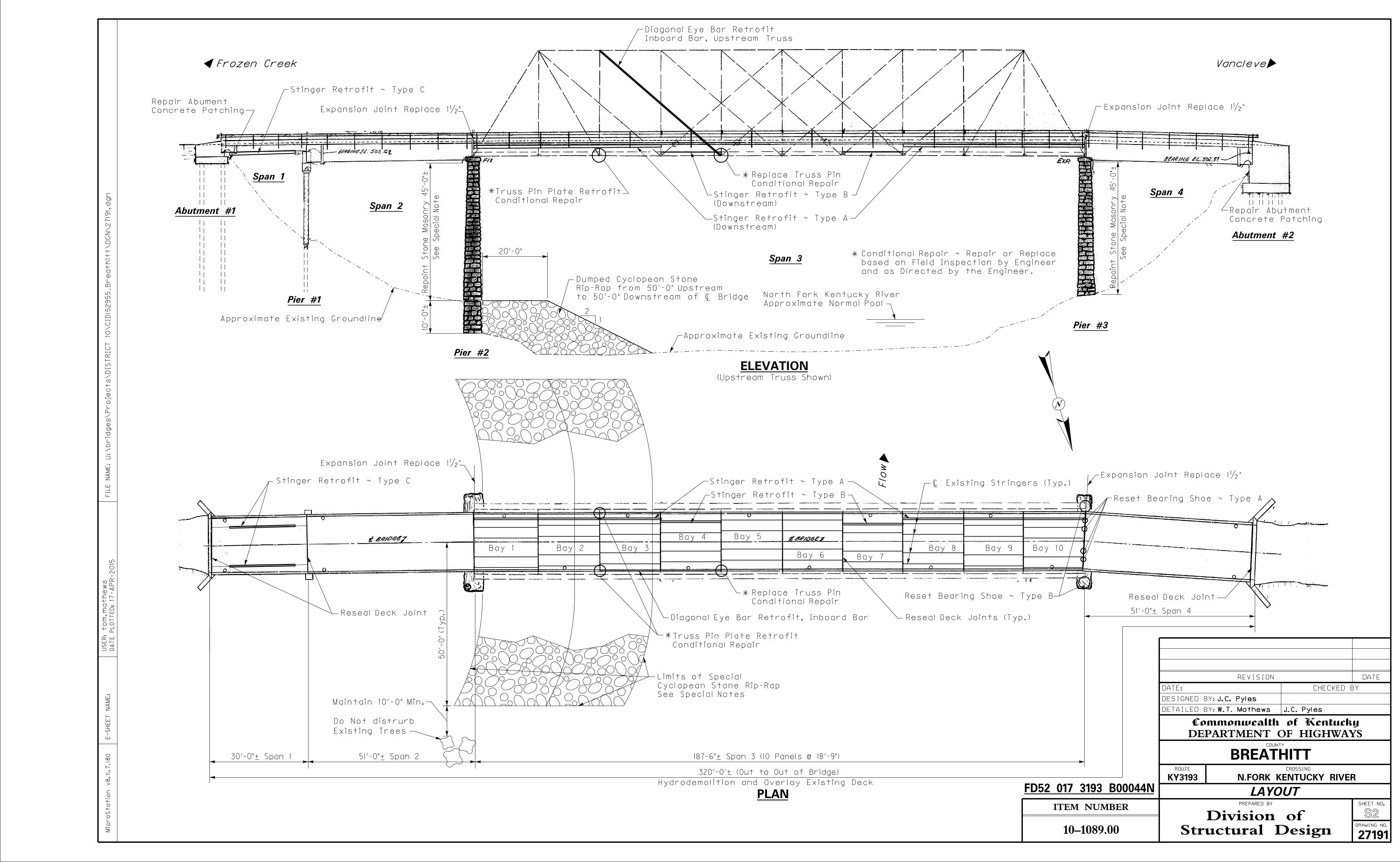
Abutment #1
Span 1
Span 2
Span 3
Span 4
Abutment #2
Pier #2
Pier #3
ELEVATION(Upstream Truss Shown)
PLAN
Approximate Normal Pool
North Fork Kentucky River
Flo
w
Inboard Bar, Upstream Truss
Diagonal Eye Bar Retrofit
30’-0"+ Span 1 51’-0"+ Span 2
51’-0"+ Span 4
320’-0’+ (Out to Out of Bridge)
Stinger Retrofit ~ Type B
Stinger Retrofit ~ Type A
Stinger Retrofit ~ Type C
Stinger Retrofit ~ Type C
Diagonal Eye Bar Retrofit, Inboard Bar
VancleveFrozen Creek
Reset Bearing Shoe ~ Type A
Reset Bearing Shoe ~ Type B
FD52 017 3193 B00044N
Concrete Patching
Repair Abument
10’-
0"+
2
1
Re
point
Sto
ne
Maso
nry
45’-
0"+
20’-0"
Re
point
Sto
ne
Maso
nry
45’-
0"+
Pier #1
(Downstream)
Stinger Retrofit ~ Type B
(Downstream)
Stinger Retrofit ~ Type A
*
*
Expansion Joint Replace 1�" Expansion Joint Replace 1�"
Expansion Joint Replace 1�"
Expansion Joint Replace 1�"
and as Directed by the Engineer.
based on Field Inspection by Engineer
Conditional Repair ~ Repair or Replace
*
to 50’-0" Downstream of ! Bridge
Rip-Rap from 50’-0" Upstream
Dumped Cyclopean Stone
Bay 1 Bay 2 Bay 3
Bay 4 Bay 5
Bay 6 Bay 7
Bay 8 Bay 9 Bay 10
187-6"+ Span 3 (10 Panels @ 18’-9")
Hydrodemolition and Overlay Existing Deck
Reseal Deck Joint
Reseal Deck Joint
50’-
0" (T
yp.)
*Conditional Repair
Truss Pin Plate Retrofit
Conditional Repair
Replace Truss Pin
*Conditional Repair
Replace Truss Pin
Existing Trees
Do Not distrurb
Maintain 10’-0" Min.
Conditional Repair
Truss Pin Plate Retrofit
See
Special
Note
See
Special
Note
Reseal Deck Joints (Typ.)
Approximate Existing Groundline
Approximate Existing Groundline
See Special Notes
Cyclopean Stone Rip-Rap
Limits of Special
! Existing Stringers (Typ.)
Concrete Patching
Repair Abutment
N
Structural DesignDivision of
E-S
HE
ET
NA
ME:
Micro
Statio
n v8.11.7.18
0
ITEM NUMBER
DRAWING NO.
SHEET NO.
Commonwealth of Kentucky
DEPARTMENT OF HIGHWAYSCOUNTY
ROUTE CROSSING
PREPARED BY
DETAILED BY:
DESIGNED BY:
DATE: CHECKED BY
REVISION DATE
10-1089.00
J.C. Pyles
W.T. Mathews J.C. Pyles
BREATHITT
KY3193 N.FORK KENTUCKY RIVER
LAYOUT
S2
27191
17-
AP
R-2015
U:\brid
ges\
Projects\
DIS
TRIC
T 10\
CID15
2955_
Breathitt\
DG
N\2719
1.dgn
FIL
E
NA
ME:
DA
TE P
LO
TT
ED:
US
ER:to
m.
mathe
ws
Abutment #1
Span 1
Span 2
Span 3
Span 4
Abutment #2
Pier #2
Pier #3
ELEVATION(Upstream Truss Shown)
PLAN
Approximate Normal Pool
North Fork Kentucky River
Flo
w
Inboard Bar, Upstream Truss
Diagonal Eye Bar Retrofit
30’-0"+ Span 1 51’-0"+ Span 2
51’-0"+ Span 4
320’-0’+ (Out to Out of Bridge)
Stinger Retrofit ~ Type B
Stinger Retrofit ~ Type A
Stinger Retrofit ~ Type C
Stinger Retrofit ~ Type C
Diagonal Eye Bar Retrofit, Inboard Bar
VancleveFrozen Creek
Reset Bearing Shoe ~ Type A
Reset Bearing Shoe ~ Type B
FD52 017 3193 B00044N
Concrete Patching
Repair Abument
10’-
0"+
2
1
Re
point
Sto
ne
Maso
nry
45’-
0"+
20’-0"
Re
point
Sto
ne
Maso
nry
45’-
0"+
Pier #1
(Downstream)
Stinger Retrofit ~ Type B
(Downstream)
Stinger Retrofit ~ Type A
*
*
Expansion Joint Replace 1�" Expansion Joint Replace 1�"
Expansion Joint Replace 1�"
Expansion Joint Replace 1�"
and as Directed by the Engineer.
based on Field Inspection by Engineer
Conditional Repair ~ Repair or Replace
*
to 50’-0" Downstream of ! Bridge
Rip-Rap from 50’-0" Upstream
Dumped Cyclopean Stone
Bay 1 Bay 2 Bay 3
Bay 4 Bay 5
Bay 6 Bay 7
Bay 8 Bay 9 Bay 10
187-6"+ Span 3 (10 Panels @ 18’-9")
Hydrodemolition and Overlay Existing Deck
Reseal Deck Joint
Reseal Deck Joint
50’-
0" (T
yp.)
*Conditional Repair
Truss Pin Plate Retrofit
Conditional Repair
Replace Truss Pin
*Conditional Repair
Replace Truss Pin
Existing Trees
Do Not distrurb
Maintain 10’-0" Min.
Conditional Repair
Truss Pin Plate Retrofit
See
Special
Note
See
Special
Note
Reseal Deck Joints (Typ.)
Approximate Existing Groundline
Approximate Existing Groundline
See Special Notes
Cyclopean Stone Rip-Rap
Limits of Special
! Existing Stringers (Typ.)
Concrete Patching
Repair Abutment
N
Structural DesignDivision of
E-S
HE
ET
NA
ME:
Micro
Statio
n v8.11.7.18
0
ITEM NUMBER
DRAWING NO.
SHEET NO.
Commonwealth of Kentucky
DEPARTMENT OF HIGHWAYSCOUNTY
ROUTE CROSSING
PREPARED BY
DETAILED BY:
DESIGNED BY:
DATE: CHECKED BY
REVISION DATE
10-1089.00
J.C. Pyles
W.T. Mathews J.C. Pyles
BREATHITT
KY3193 N.FORK KENTUCKY RIVER
REPAIR LOCATIONS
S5
27191
17-
AP
R-2015
U:\brid
ges\
Projects\
DIS
TRIC
T 10\
CID15
2955_
Breathitt\
DG
N\2719
1.dgn
FIL
E
NA
ME:
DA
TE P
LO
TT
ED:
US
ER:to
m.
mathe
ws
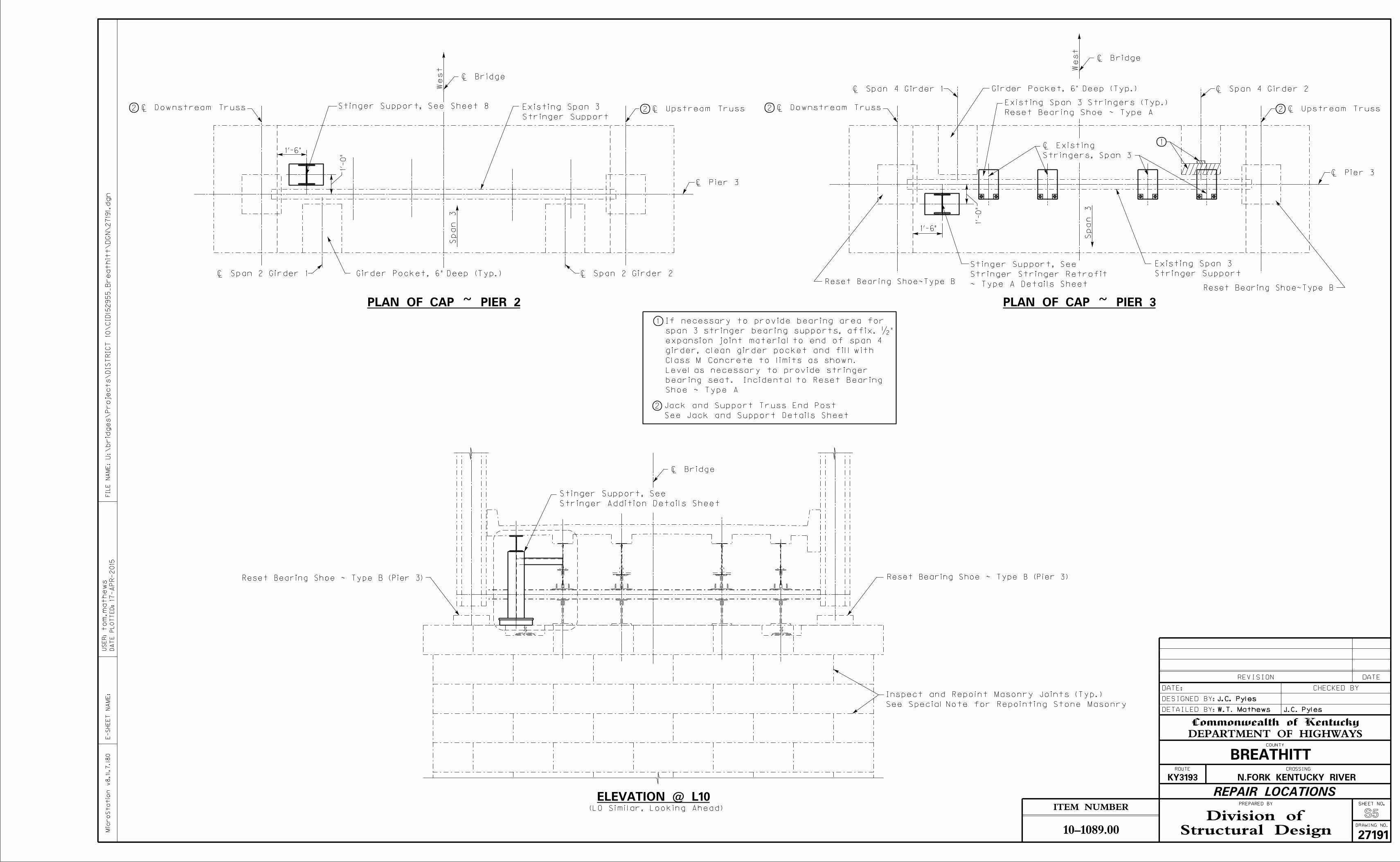
PLAN OF CAP ~ PIER 3
Girder Pocket, 6" Deep (Typ.)
1
! Downstream Truss ! Upstream Truss
Stringer Support
Existing Span 3
See Jack and Support Details Sheet
Jack and Support Truss End Post
! Bridge
1
2
2 2
! Pier 3
1’-6"
1’-0"
! Downstream Truss2 ! Upstream Truss2
1’-6"
1’-0"
Stringer Support
Existing Span 3
! Bridge
Girder Pocket, 6" Deep (Typ.)
! Span 4 Girder 2! Span 4 Girder 1
! Span 2 Girder 1 ! Span 2 Girder 2
! Pier 3
PLAN OF CAP ~ PIER 2
! Bridge
ELEVATION @ L10
Stringer Addition Details Sheet
Stinger Support, See
Reset Bearing Shoe ~ Type B (Pier 3)Reset Bearing Shoe ~ Type B (Pier 3)
Reset Bearing Shoe~Type BReset Bearing Shoe~Type B
Reset Bearing Shoe ~ Type A
Existing Span 3 Stringers (Typ.)
See Special Note for Repointing Stone Masonry
Inspect and Repoint Masonry Joints (Typ.)
Spa
n
3
Spa
n
3
Stinger Support, See Sheet 8
Stringers, Span 3
! Existing
(L0 Similar, Looking Ahead)
West W
est
~ Type A Details Sheet
Stringer Stringer Retrofit
Stinger Support, See
Shoe ~ Type A
bearing seat. Incidental to Reset Bearing
Level as necessary to provide stringer
Class M Concrete to limits as shown.
girder, clean girder pocket and fill with
expansion joint material to end of span 4
span 3 stringer bearing supports, affix. �"
If necessary to provide bearing area for

Structural DesignDivision of
E-S
HE
ET
NA
ME:
Micro
Statio
n v8.11.7.18
0
ITEM NUMBER
DRAWING NO.
SHEET NO.
Commonwealth of Kentucky
DEPARTMENT OF HIGHWAYSCOUNTY
ROUTE CROSSING
PREPARED BY
DETAILED BY:
DESIGNED BY:
DATE: CHECKED BY
REVISION DATE
10-1089.00
J.C. Pyles
W.T. Mathews J.C. Pyles
BREATHITT
KY3193 N.FORK KENTUCKY RIVER
REPAIR LOCATIONS
S5
27191
17-
AP
R-2015
U:\brid
ges\
Projects\
DIS
TRIC
T 10\
CID15
2955_
Breathitt\
DG
N\2719
1.dgn
FIL
E
NA
ME:
DA
TE P
LO
TT
ED:
US
ER:to
m.
mathe
ws
PLAN OF CAP ~ PIER 3
Girder Pocket, 6" Deep (Typ.)
1
! Downstream Truss ! Upstream Truss
Stringer Support
Existing Span 3
See Jack and Support Details Sheet
Jack and Support Truss End Post
! Bridge
1
2
2 2
! Pier 3
1’-6"
1’-0"
! Downstream Truss2 ! Upstream Truss2
1’-6"
1’-0"
Stringer Support
Existing Span 3
! Bridge
Girder Pocket, 6" Deep (Typ.)
! Span 4 Girder 2! Span 4 Girder 1
! Span 2 Girder 1 ! Span 2 Girder 2
! Pier 3
PLAN OF CAP ~ PIER 2
! Bridge
ELEVATION @ L10
Stringer Addition Details Sheet
Stinger Support, See
Reset Bearing Shoe ~ Type B (Pier 3)Reset Bearing Shoe ~ Type B (Pier 3)
Reset Bearing Shoe~Type BReset Bearing Shoe~Type B
Reset Bearing Shoe ~ Type A
Existing Span 3 Stringers (Typ.)
See Special Note for Repointing Stone Masonry
Inspect and Repoint Masonry Joints (Typ.)
Spa
n
3
Spa
n
3
Stinger Support, See Sheet 8
Stringers, Span 3
! Existing
(L0 Similar, Looking Ahead)
West W
est
~ Type A Details Sheet
Stringer Stringer Retrofit
Stinger Support, See
Shoe ~ Type A
bearing seat. Incidental to Reset Bearing
Level as necessary to provide stringer
Class M Concrete to limits as shown.
girder, clean girder pocket and fill with
expansion joint material to end of span 4
span 3 stringer bearing supports, affix. �"
If necessary to provide bearing area for
Structural DesignDivision of
E-S
HE
ET
NA
ME:
Micro
Statio
n v8.11.7.18
0
ITEM NUMBER
DRAWING NO.
SHEET NO.
Commonwealth of Kentucky
DEPARTMENT OF HIGHWAYSCOUNTY
ROUTE CROSSING
PREPARED BY
DETAILED BY:
DESIGNED BY:
DATE: CHECKED BY
REVISION DATE
10-1089.00
J.C. Pyles
W.T. Mathews J.C. Pyles
BREATHITT
KY3193 N.FORK KENTUCKY RIVER
S7
27191
17-
AP
R-2015
U:\brid
ges\
Projects\
DIS
TRIC
T 10\
CID15
2955_
Breathitt\
DG
N\2719
1.dgn
FIL
E
NA
ME:
DA
TE P
LO
TT
ED:
US
ER:to
m.
mathe
ws
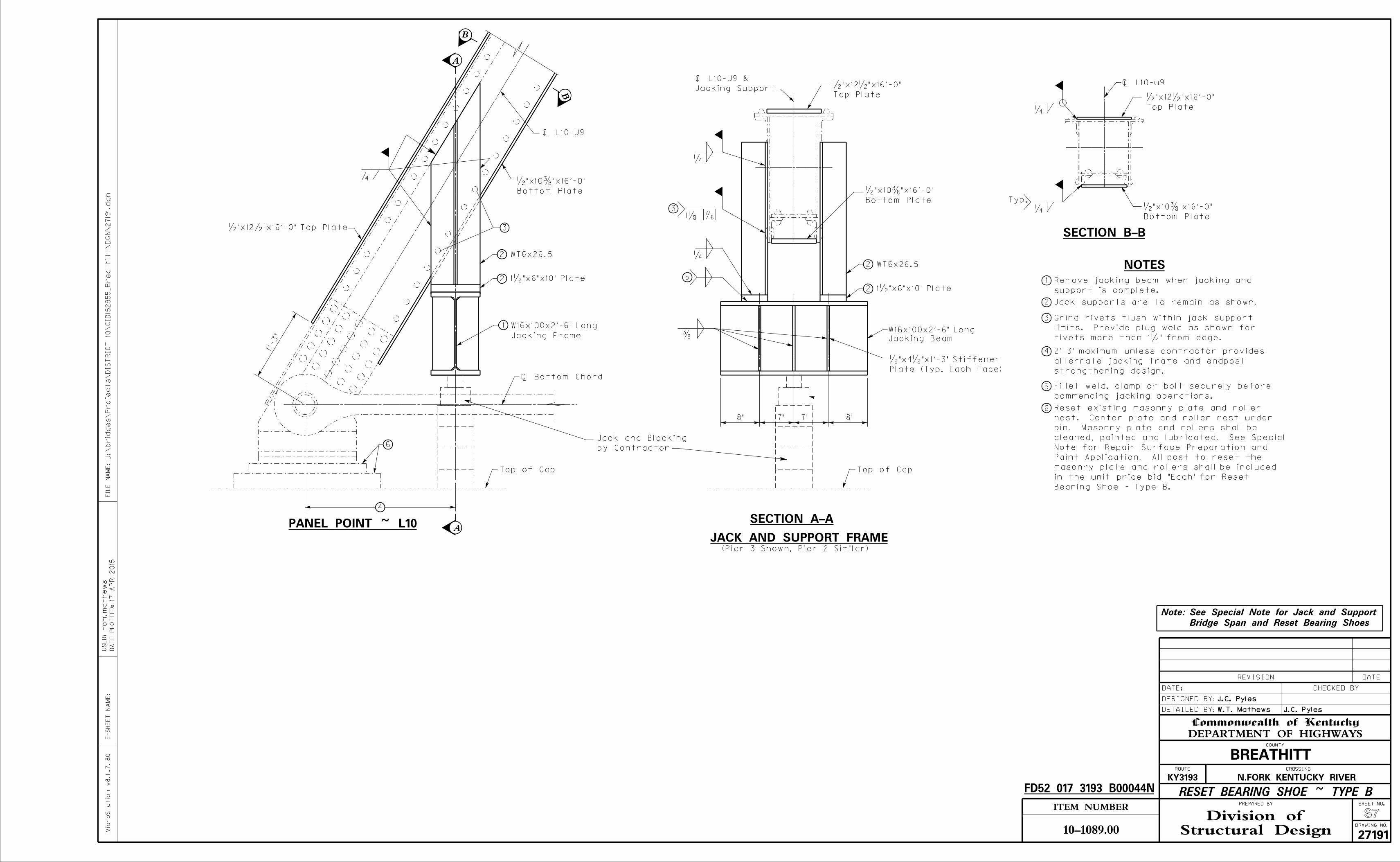
rivets more than 1�" from edge.
limits. Provide plug weld as shown for
Grind rivets flush within jack support
Jack supports are to remain as shown.
1
2
3
4
5
PANEL POINT ~ L10
1’-3"
�"x12�"x16’-0" Top Plate
6
A
1
1�"x6"x10" Plate
WT6x26.5
�
Bottom Plate
�"x10�"x16’-0"
3
2
2
4
�
2
2 1�"x6"x10" Plate
WT6x26.5
�
1� �
W16x100x2’-6" Long
SECTION A-A
3
Top Plate
�"x12�"x16’-0"
Bottom Plate
�"x10�"x16’-0"
5
6
! Bottom Chord
�
Plate (Typ. Each Face)
�"x4�"x1’-3" Stiffener
8" 7" 8"
B
A
B
Top of Cap
SECTION B-B
� Top Plate
�"x12�"x16’-0"
Bottom Plate
�"x10�"x16’-0"�
Typ.
JACK AND SUPPORT FRAME
NOTES
(Pier 3 Shown, Pier 2 Similar)
FD52 017 3193 B00044N
support is complete.
Remove jacking beam when jacking and
7"
Top of Cap
Jacking Beam
W16x100x2’-6" Long
! L10-u9
strengthening design.
alternate jacking frame and endpost
2’-3" maximum unless contractor provides
Jacking Support
! L10-U9 &
! L10-U9
Note:
Bridge Span and Reset Bearing Shoes
See Special Note for Jack and Support
RESET BEARING SHOE ~ TYPE B
Jacking Frame
commencing jacking operations.
Fillet weld, clamp or bolt securely before
Bearing Shoe - Type B.
in the unit price bid "Each" for Reset
masonry plate and rollers shall be included
Paint Application. All cost to reset the
Note for Repair Surface Preparation and
cleaned, painted and lubricated. See Special
pin. Masonry plate and rollers shall be
nest. Center plate and roller nest under
Reset existing masonry plate and roller
by Contractor
Jack and Blocking

Structural DesignDivision of
E-S
HE
ET
NA
ME:
Micro
Statio
n v8.11.7.18
0
ITEM NUMBER
DRAWING NO.
SHEET NO.
Commonwealth of Kentucky
DEPARTMENT OF HIGHWAYSCOUNTY
ROUTE CROSSING
PREPARED BY
DETAILED BY:
DESIGNED BY:
DATE: CHECKED BY
REVISION DATE
10-1089.00
J.C. Pyles
W.T. Mathews J.C. Pyles
BREATHITT
KY3193 N.FORK KENTUCKY RIVER
S7
27191
17-
AP
R-2015
U:\brid
ges\
Projects\
DIS
TRIC
T 10\
CID15
2955_
Breathitt\
DG
N\2719
1.dgn
FIL
E
NA
ME:
DA
TE P
LO
TT
ED:
US
ER:to
m.
mathe
ws
rivets more than 1�" from edge.
limits. Provide plug weld as shown for
Grind rivets flush within jack support
Jack supports are to remain as shown.
1
2
3
4
5
PANEL POINT ~ L10
1’-3"
�"x12�"x16’-0" Top Plate
6
A
1
1�"x6"x10" Plate
WT6x26.5
�
Bottom Plate
�"x10�"x16’-0"
3
2
2
4
�
2
2 1�"x6"x10" Plate
WT6x26.5
�
1� �
W16x100x2’-6" Long
SECTION A-A
3
Top Plate
�"x12�"x16’-0"
Bottom Plate
�"x10�"x16’-0"
5
6
! Bottom Chord
�
Plate (Typ. Each Face)
�"x4�"x1’-3" Stiffener
8" 7" 8"
B
A
B
Top of Cap
SECTION B-B
� Top Plate
�"x12�"x16’-0"
Bottom Plate
�"x10�"x16’-0"�
Typ.
JACK AND SUPPORT FRAME
NOTES
(Pier 3 Shown, Pier 2 Similar)
FD52 017 3193 B00044N
support is complete.
Remove jacking beam when jacking and
7"
Top of Cap
Jacking Beam
W16x100x2’-6" Long
! L10-u9
strengthening design.
alternate jacking frame and endpost
2’-3" maximum unless contractor provides
Jacking Support
! L10-U9 &
! L10-U9
Note:
Bridge Span and Reset Bearing Shoes
See Special Note for Jack and Support
RESET BEARING SHOE ~ TYPE B
Jacking Frame
commencing jacking operations.
Fillet weld, clamp or bolt securely before
Bearing Shoe - Type B.
in the unit price bid "Each" for Reset
masonry plate and rollers shall be included
Paint Application. All cost to reset the
Note for Repair Surface Preparation and
cleaned, painted and lubricated. See Special
pin. Masonry plate and rollers shall be
nest. Center plate and roller nest under
Reset existing masonry plate and roller
by Contractor
Jack and Blocking
3
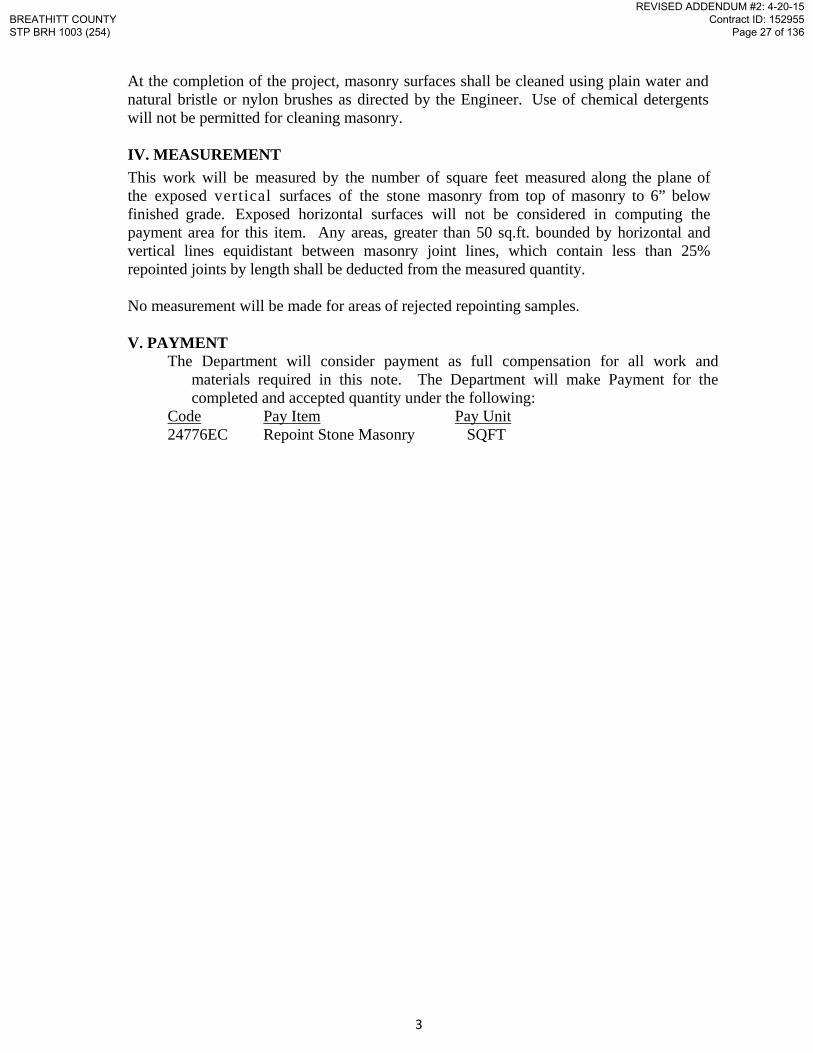
At the completion of the project, masonry surfaces shall be cleaned using plain water and natural bristle or nylon brushes as directed by the Engineer. Use of chemical detergents will not be permitted for cleaning masonry.
IV. MEASUREMENT
This work will be measured by the number of square feet measured along the plane of the exposed vertical surfaces of the stone masonry from top of masonry to 6” below finished grade. Exposed horizontal surfaces will not be considered in computing the payment area for this item. Any areas, greater than 50 sq.ft. bounded by horizontal and vertical lines equidistant between masonry joint lines, which contain less than 25% repointed joints by length shall be deducted from the measured quantity.
No measurement will be made for areas of rejected repointing samples.
V. PAYMENT The Department will consider payment as full compensation for all work and
materials required in this note. The Department will make Payment for the completed and accepted quantity under the following:
Code Pay Item Pay Unit 24776EC Repoint Stone Masonry SQFT
BREATHITT COUNTYSTP BRH 1003 (254)
REVISED ADDENDUM #2: 4-20-15Contract ID: 152955
Page 27 of 136
1/3
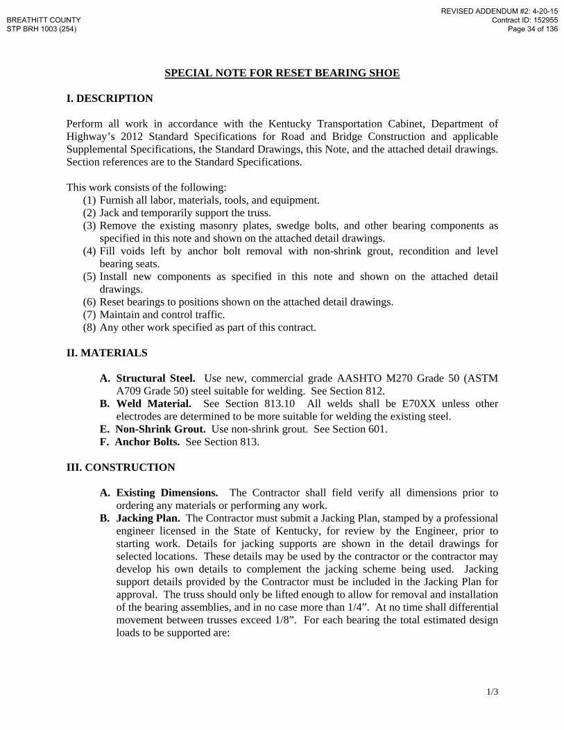
SPECIAL NOTE FOR RESET BEARING SHOE I. DESCRIPTION Perform all work in accordance with the Kentucky Transportation Cabinet, Department of Highway’s 2012 Standard Specifications for Road and Bridge Construction and applicable Supplemental Specifications, the Standard Drawings, this Note, and the attached detail drawings. Section references are to the Standard Specifications. This work consists of the following:
(1) Furnish all labor, materials, tools, and equipment. (2) Jack and temporarily support the truss. (3) Remove the existing masonry plates, swedge bolts, and other bearing components as
specified in this note and shown on the attached detail drawings. (4) Fill voids left by anchor bolt removal with non-shrink grout, recondition and level
bearing seats. (5) Install new components as specified in this note and shown on the attached detail
drawings. (6) Reset bearings to positions shown on the attached detail drawings. (7) Maintain and control traffic. (8) Any other work specified as part of this contract.
II. MATERIALS
A. Structural Steel. Use new, commercial grade AASHTO M270 Grade 50 (ASTM A709 Grade 50) steel suitable for welding. See Section 812.
B. Weld Material. See Section 813.10 All welds shall be E70XX unless other electrodes are determined to be more suitable for welding the existing steel.
E. Non-Shrink Grout. Use non-shrink grout. See Section 601. F. Anchor Bolts. See Section 813.
III. CONSTRUCTION
A. Existing Dimensions. The Contractor shall field verify all dimensions prior to ordering any materials or performing any work.
B. Jacking Plan. The Contractor must submit a Jacking Plan, stamped by a professional engineer licensed in the State of Kentucky, for review by the Engineer, prior to starting work. Details for jacking supports are shown in the detail drawings for selected locations. These details may be used by the contractor or the contractor may develop his own details to complement the jacking scheme being used. Jacking support details provided by the Contractor must be included in the Jacking Plan for approval. The truss should only be lifted enough to allow for removal and installation of the bearing assemblies, and in no case more than 1/4”. At no time shall differential movement between trusses exceed 1/8”. For each bearing the total estimated design loads to be supported are:
BREATHITT COUNTY STP BRH 1003 (254)
REVISED ADDENDUM #2: 4-20-15 Contract ID: 152955
Page 34 of 136
2/3
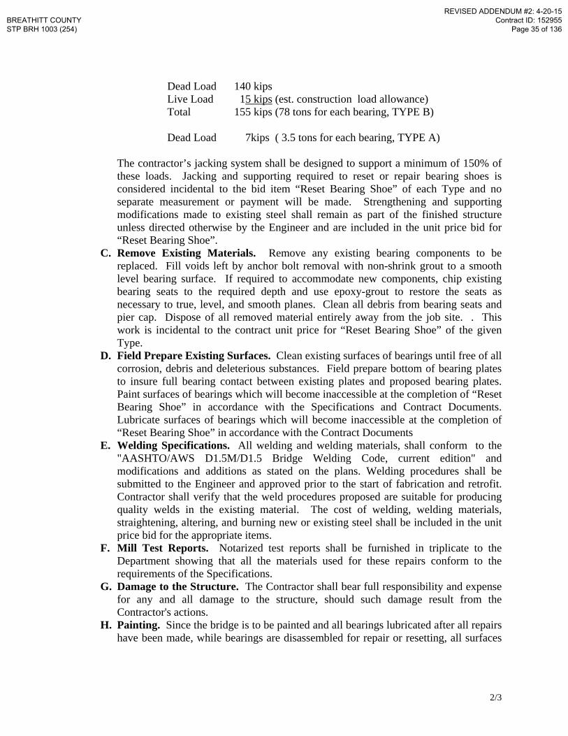
Dead Load 140 kips Live Load 15 kips (est. construction load allowance) Total 155 kips (78 tons for each bearing, TYPE B) Dead Load 7kips ( 3.5 tons for each bearing, TYPE A)
The contractor’s jacking system shall be designed to support a minimum of 150% of these loads. Jacking and supporting required to reset or repair bearing shoes is considered incidental to the bid item “Reset Bearing Shoe” of each Type and no separate measurement or payment will be made. Strengthening and supporting modifications made to existing steel shall remain as part of the finished structure unless directed otherwise by the Engineer and are included in the unit price bid for “Reset Bearing Shoe”.
C. Remove Existing Materials. Remove any existing bearing components to be replaced. Fill voids left by anchor bolt removal with non-shrink grout to a smooth level bearing surface. If required to accommodate new components, chip existing bearing seats to the required depth and use epoxy-grout to restore the seats as necessary to true, level, and smooth planes. Clean all debris from bearing seats and pier cap. Dispose of all removed material entirely away from the job site. . This work is incidental to the contract unit price for “Reset Bearing Shoe” of the given Type.
D. Field Prepare Existing Surfaces. Clean existing surfaces of bearings until free of all corrosion, debris and deleterious substances. Field prepare bottom of bearing plates to insure full bearing contact between existing plates and proposed bearing plates. Paint surfaces of bearings which will become inaccessible at the completion of “Reset Bearing Shoe” in accordance with the Specifications and Contract Documents. Lubricate surfaces of bearings which will become inaccessible at the completion of “Reset Bearing Shoe” in accordance with the Contract Documents
E. Welding Specifications. All welding and welding materials, shall conform to the "AASHTO/AWS D1.5M/D1.5 Bridge Welding Code, current edition" and modifications and additions as stated on the plans. Welding procedures shall be submitted to the Engineer and approved prior to the start of fabrication and retrofit. Contractor shall verify that the weld procedures proposed are suitable for producing quality welds in the existing material. The cost of welding, welding materials, straightening, altering, and burning new or existing steel shall be included in the unit price bid for the appropriate items.
F. Mill Test Reports. Notarized test reports shall be furnished in triplicate to the Department showing that all the materials used for these repairs conform to the requirements of the Specifications.
G. Damage to the Structure. The Contractor shall bear full responsibility and expense for any and all damage to the structure, should such damage result from the Contractor's actions.
H. Painting. Since the bridge is to be painted and all bearings lubricated after all repairs have been made, while bearings are disassembled for repair or resetting, all surfaces
BREATHITT COUNTY STP BRH 1003 (254)
REVISED ADDENDUM #2: 4-20-15 Contract ID: 152955
Page 35 of 136

3/3
which will be inaccessible after the work is complete shall be painted in accordance with the specifications.
I. Shop Plans. Shop plans will not be required for the items covered by this Special Note. The Contractor is responsible for obtaining field measurements and supplying properly sized materials to complete the work.
J. Prohibited Field Welding. No welding of any nature shall be performed on the bridge except as shown on the attached drawings without the written consent of the Director, Division of Bridge Design, and then only in the manner and at the locations designated in the authorization.
IV. MEASUREMENT
Reset Bearing Shoe . Measurement will be for each bearing reset of a given Type. .
V. PAYMENT
A. Reset Bearing Shoe. Payment at the contract unit price is full compensation for removal and disposing of specified materials, furnishing and placing non-shrink grout, jacking and supporting required to reset or repair the bearings, furnishing and installing steel plates and anchor bolts, welding, and all other materials, labor, equipment, tools, and incidentals necessary to complete the work as specified by this note. Payment shall be made under:
Code Pay Item Pay Unit 03305 Reset Bearing Shoe, Type A Each 03305 Reset Bearing Shoe, Type B Each
BREATHITT COUNTY STP BRH 1003 (254)
REVISED ADDENDUM #2: 4-20-15 Contract ID: 152955
Page 36 of 136

SPECIAL NOTE FOR TRUSS PIN REPLACEMENT I. DESCRIPTION Perform all work in accordance with the Kentucky Transportation Cabinet, Department of Highway’s 2012 Standard Specifications for Road and Bridge Construction and applicable Supplemental Specifications, the Standard Drawings, this Note, and the attached detail drawings. This work consists of the following:
(1) Furnish all labor, materials, tools, and equipment (2) Replace truss pin in accordance with the detail drawings and this Special
Note. (3) Maintain and control traffic as necessary (4) Any other work specified as part of this contract
II. MATERIALS
A. Steel. Use new, AASHTO M270 Grade 50 (ASTM A709 Grade 50) steel.
The Engineer will base acceptance on visual inspection. See Section 812. B. High Strength Bolts, Nuts, and Washers. Ensure all bolted connections
are AASHTO M164 or ASTM A325 high strength bolts, nuts, and washers. C. Pins. Conform to ASTM A108 or ASTM A688 steel in accordance with
Section 813. Finish pins in accordance with the Section 607.03.09. Provide pin nuts, washers, etc. as required and in accordance with the specifications.
III. CONSTRUCTION
A. Truss Pin Replacement 1. This repair is a Conditional Repair. Do not construct this repair unless
directed by the Engineer. 2. Field measure pin and fabricate to match field measurements. Adjust plan
dimensions to match field conditions. 3. Install pin as shown on the detail drawings. 4. Paint new structural steel and retouch existing structural steel damaged by
the repair operations in accordance with the specifications using a color similar to existing unless otherwise shown on the plans or directed by the Engineer.
B. Dimensions. Dimensions shown on these plans are taken from available plans and do not necessarily reflect revisions made during construction. The Contractor shall verify elevations, and dimensions, including thickness of parts, in the field prior to ordering materials or fabricating steel.
C. Shop Drawings. Shop drawings will not be required. The Contractor is responsible for obtaining field measurements and supplying properly sized materials to complete the work.
BREATHITT COUNTY STP BRH 1003 (254)
ADDED ADDENDUM #2: 4-20-15 Contract ID: 152955
Page 39(a) of 136
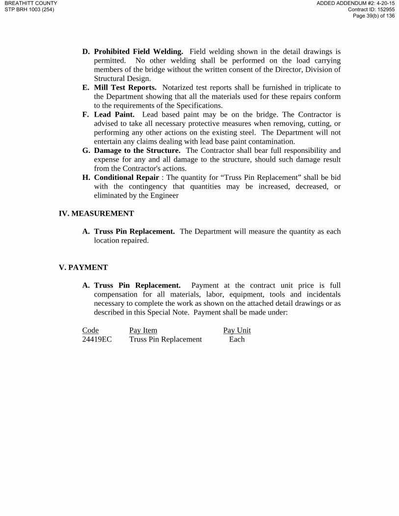
D. Prohibited Field Welding. Field welding shown in the detail drawings is permitted. No other welding shall be performed on the load carrying members of the bridge without the written consent of the Director, Division of Structural Design.
E. Mill Test Reports. Notarized test reports shall be furnished in triplicate to the Department showing that all the materials used for these repairs conform to the requirements of the Specifications.
F. Lead Paint. Lead based paint may be on the bridge. The Contractor is advised to take all necessary protective measures when removing, cutting, or performing any other actions on the existing steel. The Department will not entertain any claims dealing with lead base paint contamination.
G. Damage to the Structure. The Contractor shall bear full responsibility and expense for any and all damage to the structure, should such damage result from the Contractor's actions.
H. Conditional Repair : The quantity for “Truss Pin Replacement” shall be bid with the contingency that quantities may be increased, decreased, or eliminated by the Engineer
IV. MEASUREMENT
A. Truss Pin Replacement. The Department will measure the quantity as each
location repaired. V. PAYMENT
A. Truss Pin Replacement. Payment at the contract unit price is full
compensation for all materials, labor, equipment, tools and incidentals necessary to complete the work as shown on the attached detail drawings or as described in this Special Note. Payment shall be made under:
Code Pay Item Pay Unit 24419EC Truss Pin Replacement Each
BREATHITT COUNTY STP BRH 1003 (254)
ADDED ADDENDUM #2: 4-20-15 Contract ID: 152955
Page 39(b) of 136
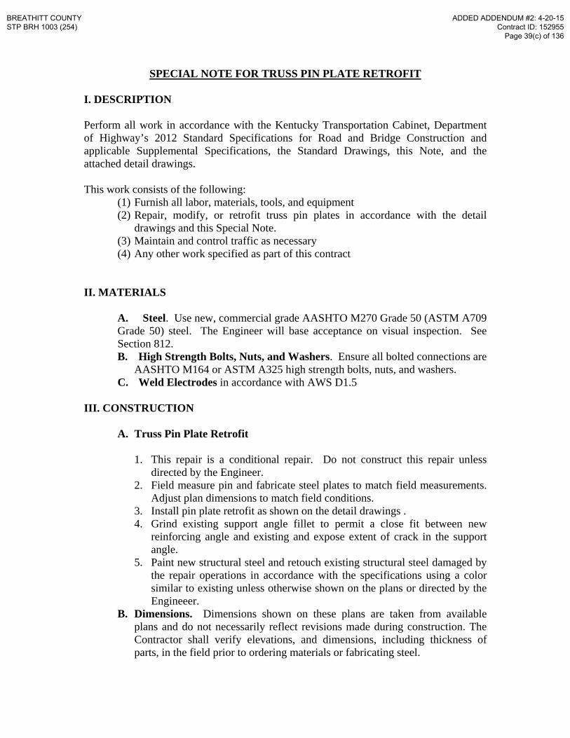
SPECIAL NOTE FOR TRUSS PIN PLATE RETROFIT I. DESCRIPTION Perform all work in accordance with the Kentucky Transportation Cabinet, Department of Highway’s 2012 Standard Specifications for Road and Bridge Construction and applicable Supplemental Specifications, the Standard Drawings, this Note, and the attached detail drawings. This work consists of the following:
(1) Furnish all labor, materials, tools, and equipment (2) Repair, modify, or retrofit truss pin plates in accordance with the detail
drawings and this Special Note. (3) Maintain and control traffic as necessary (4) Any other work specified as part of this contract
II. MATERIALS
A. Steel. Use new, commercial grade AASHTO M270 Grade 50 (ASTM A709 Grade 50) steel. The Engineer will base acceptance on visual inspection. See Section 812. B. High Strength Bolts, Nuts, and Washers. Ensure all bolted connections are
AASHTO M164 or ASTM A325 high strength bolts, nuts, and washers. C. Weld Electrodes in accordance with AWS D1.5
III. CONSTRUCTION
A. Truss Pin Plate Retrofit
1. This repair is a conditional repair. Do not construct this repair unless directed by the Engineer.
2. Field measure pin and fabricate steel plates to match field measurements. Adjust plan dimensions to match field conditions.
3. Install pin plate retrofit as shown on the detail drawings . 4. Grind existing support angle fillet to permit a close fit between new
reinforcing angle and existing and expose extent of crack in the support angle.
5. Paint new structural steel and retouch existing structural steel damaged by the repair operations in accordance with the specifications using a color similar to existing unless otherwise shown on the plans or directed by the Engineeer.
B. Dimensions. Dimensions shown on these plans are taken from available plans and do not necessarily reflect revisions made during construction. The Contractor shall verify elevations, and dimensions, including thickness of parts, in the field prior to ordering materials or fabricating steel.
BREATHITT COUNTY STP BRH 1003 (254)
ADDED ADDENDUM #2: 4-20-15 Contract ID: 152955
Page 39(c) of 136

C. Shop Drawings. Shop drawings will not be required. The Contractor is responsible for obtaining field measurements and supplying properly sized materials to complete the work.
D. Prohibited Field Welding. Field welding shown in the detail drawings is permitted. No other welding shall be performed on the load carrying members of the bridge without the written consent of the Director, Division of Structural Design.
E. Mill Test Reports. Notarized test reports shall be furnished in triplicate to the Department showing that all the materials used for these repairs conform to the requirements of the Specifications.
F. Lead Paint. Lead based paint may be on the bridge. The Contractor is advised to take all necessary protective measures when removing, cutting, or performing any other actions on the existing steel. The Department will not entertain any claims dealing with lead base paint contamination.
G. Damage to the Structure. The Contractor shall bear full responsibility and expense for any and all damage to the structure, should such damage result from the Contractor's actions.
H. Conditional Repair : The quantity for “Truss Pin Plate Retrofit” shall be bid with the contingency that quantities may be increased, decreased, or eliminated by the Engineer
IV. MEASUREMENT
A. Truss Pin Plate Retrofit. The Department will measure the quantity as each
location repaired. V. PAYMENT
A. Truss Pin Plate Retrofit. Payment at the contract unit price is full
compensation for all materials, labor, equipment, tools and incidentals necessary to complete the work as shown on the attached detail drawings or as described in this Special Note. Payment shall be made under:
Code Pay Item Pay Unit 24420EC Truss Pin Plate Retrofit Each
BREATHITT COUNTY STP BRH 1003 (254)
ADDED ADDENDUM #2: 4-20-15 Contract ID: 152955
Page 39(d) of 136
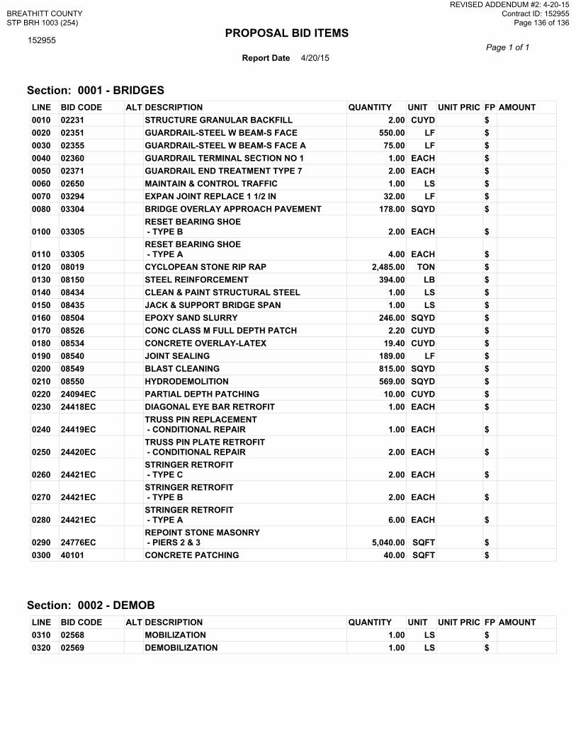
PROPOSAL BID ITEMS
Report Date 4/20/15Page 1 of 1
152955
Section: 0001 - BRIDGESLINE BID CODE ALT DESCRIPTION QUANTITY UNIT UNIT PRIC FP AMOUNT0010 02231 STRUCTURE GRANULAR BACKFILL 2.00 CUYD $0020 02351 GUARDRAIL-STEEL W BEAM-S FACE 550.00 LF $0030 02355 GUARDRAIL-STEEL W BEAM-S FACE A 75.00 LF $0040 02360 GUARDRAIL TERMINAL SECTION NO 1 1.00 EACH $0050 02371 GUARDRAIL END TREATMENT TYPE 7 2.00 EACH $0060 02650 MAINTAIN & CONTROL TRAFFIC 1.00 LS $0070 03294 EXPAN JOINT REPLACE 1 1/2 IN 32.00 LF $0080 03304 BRIDGE OVERLAY APPROACH PAVEMENT 178.00 SQYD $
0100 03305RESET BEARING SHOE - TYPE B 2.00 EACH $
0110 03305RESET BEARING SHOE - TYPE A 4.00 EACH $
0120 08019 CYCLOPEAN STONE RIP RAP 2,485.00 TON $0130 08150 STEEL REINFORCEMENT 394.00 LB $0140 08434 CLEAN & PAINT STRUCTURAL STEEL 1.00 LS $0150 08435 JACK & SUPPORT BRIDGE SPAN 1.00 LS $0160 08504 EPOXY SAND SLURRY 246.00 SQYD $0170 08526 CONC CLASS M FULL DEPTH PATCH 2.20 CUYD $0180 08534 CONCRETE OVERLAY-LATEX 19.40 CUYD $0190 08540 JOINT SEALING 189.00 LF $0200 08549 BLAST CLEANING 815.00 SQYD $0210 08550 HYDRODEMOLITION 569.00 SQYD $0220 24094EC PARTIAL DEPTH PATCHING 10.00 CUYD $0230 24418EC DIAGONAL EYE BAR RETROFIT 1.00 EACH $
0240 24419ECTRUSS PIN REPLACEMENT - CONDITIONAL REPAIR 1.00 EACH $
0250 24420ECTRUSS PIN PLATE RETROFIT - CONDITIONAL REPAIR 2.00 EACH $
0260 24421ECSTRINGER RETROFIT - TYPE C 2.00 EACH $
0270 24421ECSTRINGER RETROFIT - TYPE B 2.00 EACH $
0280 24421ECSTRINGER RETROFIT - TYPE A 6.00 EACH $
0290 24776ECREPOINT STONE MASONRY - PIERS 2 & 3 5,040.00 SQFT $
0300 40101 CONCRETE PATCHING 40.00 SQFT $
Section: 0002 - DEMOBLINE BID CODE ALT DESCRIPTION QUANTITY UNIT UNIT PRIC FP AMOUNT0310 02568 MOBILIZATION 1.00 LS $0320 02569 DEMOBILIZATION 1.00 LS $
BREATHITT COUNTY STP BRH 1003 (254)
REVISED ADDENDUM #2: 4-20-15 Contract ID: 152955
Page 136 of 136


![Untitled Document 1 [transportation.ky.gov]transportation.ky.gov/Construction-Procurement/Project Related... · Title: Untitled Document 1 Author: h2519 Created Date: 6/10/2011 10:43:24](https://img.dokumen.tips/doc/110x75/5c8f435009d3f2ec738c56c5/untitled-document-1-related-title-untitled-document-1-author-h2519.jpg)


![Breathitt County news. (Jackson, KY) 1908-04-03 [p ]](https://img.dokumen.tips/doc/110x75/62c13c2590d81e1b60328609/breathitt-county-news-jackson-ky-1908-04-03-p-.jpg)

![Breathitt County news. (Jackson, KY) 1904-08-12 [p ]](https://img.dokumen.tips/doc/110x75/61b263cec11b8d412617d755/breathitt-county-news-jackson-ky-1904-08-12-p-.jpg)