Embed Size (px)
Citation preview


Approved for public release; Distribution is unlimited;
OPSEC review conducted on 26 September 2012
US Army White Sands Missile Range
Range Customer Handbook 2012 WSMR Business Development Office
[email protected] www.wsmr.army.mil
866-532-9767
Contents
Chapter One: Introduction to the Range
Welcome 2 Contact Information 2 Program Portfolio 3 Overview of the Range 8 Mission Statement 9 Land, Airspace, and Geographical Infrastructure 9 Range Organizational Structure 12
Chapter Two: Inter facing with the Range
Doing Business with the Range 16 Sponsor Organizations 19
Chapter Three: Mission Planning on the Range
Universal Documentation System 24 Range Policy 25
Environmental Considerations Policy 25 Safety Policy 29 Range Operations Mission Scheduling Policy 31 Frequency Utilization and Management Policy 34 Airspace Policy 35 Resource Management Policy 35
Test Program Management Systems 35

Chapter Four: Mission Execution on the Range
Data Collection Systems 40 Telemetry Instrumentation 40 Radar Instrumentation 41 Transponder Instrumentation 42 Global Positioning Systems Instrumentation 42 Timing Instrumentation 43 Optical Instrumentation 43 Meteorology Instrumentation 44 Field Integration Instrumentation 46 Mobile Range Instrumentation 46 Army Aviation Instrumentation 46 Target Control Instrumentation 47
Data Distribution Systems 48 Netcentric Communications 48 Telephonic Communications 49 Radio Communications 50 Network Communications 50 Frequency Utilization and Management Communications 51
Data Analysis Systems 51 Reliability, Availability and Maintainability (RAM) 51 Manpower and Personnel Integration (MANPRINT) 52 Human Factors Engineering (HFE) 52 Warheads 52 Post Test Data Reduction 53 Visual Information (VI) Products 53
Facilities and Laboratories 54 Nuclear Weapons Effects 54 Electromagnetic Environment Effects 56 Directed Energy Weapons Effects 57 Space Effects 58 High Power Microwave Electromagnetic Environment Effects 58
High Energy Laser Systems Test Facility (HELSTF) 59 Life Cycle Management 61 Radiation Tolerance Assured Supply And Support Center (RTASSC) 61 Applied Environments 61 Climatic Test Facilities 61
Dynamic Test Facilities 62 Aerial Cable Facilities 63 Metallurgy Laboratory 64 Chemistry Laboratory 64

Team White Sands Missile Range (Team WSMR) 66 Naval Surface Warfare Center Port Hueneme Division Detachment
White Sands (NSWCPHD - DET WS) 66 Air Force 46th Test Group Detachment 1 (DET 1, 46th TG) 68 Assistant Secretary Of The Army For Acquisition, Logistics And Technology
(ASAALT) System Of Systems Integration (SoSI) Directorate 71 National Aeronautics and Space Administration (NASA) 73 National Reconnaissance Office (NRO), Aerospace Data Facility-Southwest (ADF-SW) 73 Training And Doctrine Command (TRADOC) Requirements Analysis Center (TRAC) 74 Defense Threat Reduction Agency (DTRA) 74 Army Research Laboratory (ARL) 75 Center for Countermeasures (The Center) 77 National Geospatial Intelligence Agency (NGA) 80
Chapter Five: Visiting the Range
Directions to White Sands Missile Range 82 Visit Requests 84 Visiting the Range 84 Unexploded Ordnance (UXO) 87 Installation Hours of Operation 88 Smoking Policy 88
Chapter Six: At Home on the Range
Family & Morale, Welfare and Recreation (F&MWR) 90 Army and Air Force Exchange Service (AAFES) 92 United States Post Office 93 Internet Access 93 Telephone 93
White Sands Missile Range Dialing Table 95 White Sands Missile Range Main Post Area Map 96

iv
Appendices: Airspace Appendix 101
General Policy 101 Flight Restrictions 103 Restricted Airspace 103 HAFB Sub-Divided Airspace Available for Recall by WSMR 104
Training Missions Appendix 105
Ground Safety Appendix 111
Procedures 111 Safety Standing Operating Procedure (SSOP) 111 Certification of Hazards 111
Flight Safety Appendix 113
Safety Policies and Approvals 113 General Policy 113 Real-Time Safety Management Tracking 115 Systems Requiring Flight Termination System 115
Systems Not Requiring Flight Termination System 115 Off-Range Launch and Flight Corridors 115
Flight Termination Requirements 116 Flight Termination System Requirements 116 Flight Safety Information Requirements 117
System Description 117 System Physical Description 117 System Functional Description 117
Trajectory Information 118 Vehicle Failure Modes and Performance Characteristics 119
Laser Safety Appendix 121
Categories of Operation 121 Procedures 121 Documentation 122
Explosive Ordnance Disposal Appendix 123
Frequency Utilization and Management Policy Appendix 125
Process Authorization 125 Electronic Countermeasure Activities 126 Frequency Surveillance Stations 127 Frequency Surveillance Support 127 Other Communication Systems 127
Test Program Management Systems Appendix 129
Vision Digital Library System (VDLS) 129
v
Request for Test Services (RFTS) 129
Telemetry Systems Appendix 133 Data Capabilities 133 Telemetry Data Center 134
Radar Systems Instrumentation Appendix 135 Army Navy Mobile Pulsed System (AN/MPS)-39 Multiple Object Tracking Radar 135 Multiple Object Tracking Radar (MOTR) System Description 135 Multiple Object Tracking Radar (MOTR) Data Products 136 Army Navy Fixed Pulsed System (AN/FPS)-16 Instrumentation Radar 137
System Description 138 Data Products 139
CW Weibel Doppler Radar 140 Data Products 140 System Description 141
Transponders Instrumentation Appendix 143 Radar Transponders 143 Customer Transponders 143
Global Positioning Systems Instrumentation Appendix 145
Advanced Range Data System (ARDS) 145 Global Positioning System (GPS) Small Box Configuration 145
Timing Instrumentation Appendix 147
Optical Instrumentation Appendix 149
Remote Instrument Control System (RICS) 149 Distant Object Attitude Measurement System (DOAMS) 149 Fixed Camera System 149 Non-Track and Closed Circuit Television 149 Flight Follower (FF) 150 Mobile Television Vans (MTV) 150 Video Relay Capability 150 Battlespace Real-Time Video (BRTV) 150 Mobile Infrared Telescope (MIRT) 151 Optics Remote Control and Acquisition (ORCA) 151 Virtually Integrated System for Optical Replay (VISOR) 151
Meteorology Instrumentation Appendix 153
Upper Air Measurement System (UAMS) 153 Surface Automated Measurement System (SAMS) 153 Atmospheric Profiler Measurement System (APMS) 153 Four Dimensional Weather Modeling (4DWX) 154 Lightning Map Array (LMA) 154 Wind Finding Radar (WFR) 155 Smart Impact Prediction System (SMART-IP) 155

vi
Data Products 156
Data Distribution Systems Appendix 159 Inter-Range Control Center (IRCC) 159 Distributed Test Support 159 Common Control Node 160 Test Support Network-Internet Protocol (TSP-IN) 150 Transport 160 Technical Capabilities 162 Mission Support Data 165
Data Analysis Systems Appendix 167 Reliability, Availability and Maintainability (RAM) 167 RAM Integrated Logistics Support (ILS) 167 SANDS Technical Data Center 167 Manpower and Personnel Integration (MANPRINT) 167 Human Factors Engineering (HFE) 168 System Safety Evaluations 168 Software Test and Analysis 169 System Engineering 170 Software Engineering 171 Hazardous Test Area (HTA) 171 Impact Areas 172 Special Purpose Areas 173 Safety Aspects of Impact Areas 173 Program Support 174 Test Officer Support 174
Post Test Data Reduction Appendix 175
Data Product Categories 175 Data Product Formats 177 Data Delivery 181
Visual Information (VI) Products Appendix 183
Nuclear Weapons Effects Facilities Appendix 185
Relativistic Electron Beam Accelerator (REBA) 185 Linear Electron Accelerator (LINAC) 185 Fast Burst Reactor (FBR) 186 Gamma Radiation Facility (GRF) 186 White Sands Solar Furnace (WSSF) 186 Semiconductor Test Laboratory (STL) 187 Directed Energy Weapons Effects 187
LASER Facilities 187 Pulsed Laser Vulnerability Test System (PLVTS) 187
Climatic Test Facilities Appendix 189

vii
Large Test Chamber (LTC) 189 Small Test Chamber (STC) 189 Salt Fog/Humidity Chamber 189 Environmental Test Area II (ETA II) 189 Hot Chamber 190 Altitude Capabilities 190 Field Conditioning Equipment 190
Dynamic Test Facilities Appendix 191 Vibration Test Capabilities 191 Shock Test Capabilities 192 Propulsion Test Capabilities 193 Acceleration Test Capabilities 193 Data Acquisition Capabilities 193 Data Processing Capabilities 193 Instrumentation Capabilities 193 Load Testing and Center Of Gravity Test Capabilities 193
Chemistry Laboratory Appendix 197
Air Force 46th Test Group Detachment 1 Appendix 197
746th Test Squadron Central Inertial Guidance Test Facility (CIGTF) 197 Global Positioning System (GPS) Electronic Combat (EC) Testing 197 Sled Testing 197 Flight Testing 197 Reference Systems 197 Test Support Network (TSN) 198 Laboratory Testing 198 GPS Receiver and Integrated System Testing 198 Environmental Testing 198
846th Test Squadron 198 Holloman High Speed Test Track (HSTT) 198 National Radar Cross Section Test Facility 200
586th Flight Test Squadron 201
Center for Countermeasures Appendix 203 Methodology 203 Functional Areas 203 Field Instrumentation and Equipment 203 Digital Enhanced Seeker Van (DESV) 203 Kineto Tracking Mount (KTM) 203 Remote Launcher System 203 Joint Mobile Infrared Countermeasure Testing System (JMITS) 204 Pyrotechnics 204 Fog, Smoke, and Foam Generators 204 Millimeter Wave Electronic Countermeasure (ECM) Threat Simulator 204 Sources 204 Laser Laboratory Facilities 204

viii
Millimeter Wave Laboratory (MMWL) 204 Radiometric Support 204 Information System (IS) 205 Client/Server Computer Services 205 Production Services 205
Family & Morale, Welfare and Recreation Appendix 207
References 209
Notes 211
Acronyms 213
Reverse Acronyms 223
Index 235


2
Welcome to White Sands Missile Range
Birthplace of America’s Missile & Space Activity
This handbook has been developed to help you get the most out of your program and outlines the process for interfacing with the US Army White Sands Missile Range for test planning and execution. You will find an overview of Range capabilities and useful administrative information to address many of your questions. The Appendices offer comprehensive policy guidelines, processes, and technical specifications; and an asterisk (*) in a section title denotes an appendix associated with that section. You will also find a description of primary Range organizations, functions, and capabilities, and a summary of the Universal Documentation System (UDS), a Range tool that integrates your testing or training requirements with Range protocol. Early coordination with the Range is recommended for seamless integration of your program requirements with Range procedures.
CONTACT INFORMATION: White Sands Missile Range Business Development Office [email protected] www.wsmr.army.mil 1-866-532-9767
Commander US Army White Sands Missile Range ATTN: TEDT-WS-CSPB White Sands Missile Range New Mexico 88002
3
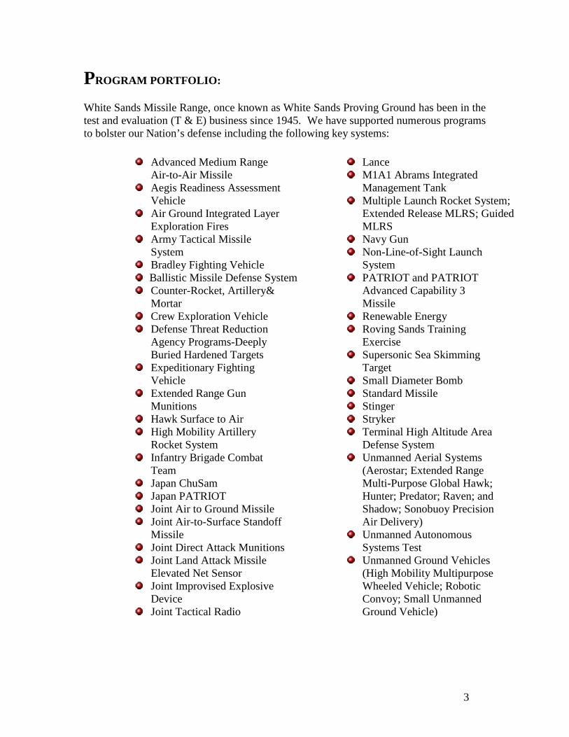
PROGRAM PORTFOLIO: White Sands Missile Range, once known as White Sands Proving Ground has been in the test and evaluation (T & E) business since 1945. We have supported numerous programs to bolster our Nation’s defense including the following key systems:
Advanced Medium Range Air-to-Air Missile
Aegis Readiness Assessment Vehicle
Air Ground Integrated Layer Exploration Fires
Army Tactical Missile System
Bradley Fighting Vehicle Ballistic Missile Defense System Counter-Rocket, Artillery&
Mortar Crew Exploration Vehicle Defense Threat Reduction
Agency Programs-Deeply Buried Hardened Targets
Expeditionary Fighting Vehicle
Extended Range Gun Munitions
Hawk Surface to Air High Mobility Artillery
Rocket System Infantry Brigade Combat
Team Japan ChuSam Japan PATRIOT Joint Air to Ground Missile Joint Air-to-Surface Standoff
Missile Joint Direct Attack Munitions Joint Land Attack Missile
Elevated Net Sensor Joint Improvised Explosive
Device Joint Tactical Radio
Lance M1A1 Abrams Integrated
Management Tank Multiple Launch Rocket System;
Extended Release MLRS; Guided MLRS
Navy Gun Non-Line-of-Sight Launch
System PATRIOT and PATRIOT
Advanced Capability 3 Missile
Renewable Energy Roving Sands Training
Exercise Supersonic Sea Skimming
Target Small Diameter Bomb Standard Missile Stinger Stryker Terminal High Altitude Area
Defense System Unmanned Aerial Systems
(Aerostar; Extended Range Multi-Purpose Global Hawk; Hunter; Predator; Raven; and Shadow; Sonobuoy Precision Air Delivery)
Unmanned Autonomous Systems Test
Unmanned Ground Vehicles (High Mobility Multipurpose Wheeled Vehicle; Robotic Convoy; Small Unmanned Ground Vehicle)

4
On range and off, we plan, conduct, analyze, and report the results of developmental, production, and other missions in the following areas:
Active Protection Systems Air and missile defense systems Aircraft systems:
Aircraft Armaments Fixed-Wing; Aircraft Survivability Equipment
Air Delivery Systems/Air Drop Antenna Testing Command, Control, Communications, & Computers, Intelligence,
Surveillance and Reconnaissance (C4ISR): C4 Systems Integrated within Missile/Automotive/Vehicle Systems; Surveillance/Reconnaissance, Information Warfare, Intelligence, and
Navigation Systems; Target Acquisition Architectures
Directed energy weapons: HPM; Laser
Electronic Countermeasures: Improvised Explosive Devices (IED)
Electromagnetic environmental effects (E3): Electromagnetic Interference (EMI)/Electromagnetic Compatibility
(EMC), Electromagnetic Pulse (EMP); HERO, HERF, HERP; electrical bonding, external grounds, and EMCON Aviation safety of flight
Electronic Warfare Indirect Fire Systems:
Indirect Fire Weapon Systems
Missiles/rockets (non-aviation): Line/Non Line of sight; propulsion systems; components/subsystems
Non-Lethal Weapons Nuclear weapons effects tests Optical and Electro-optical systems System-of-systems integration:
Army Brigade Combat Team (ABCTM) Level Live; Distributed Testing (Inter-Range Control Center)
Unmanned Aircraft Systems: Weapons Integration Performance
Unmanned Ground Vehicles Vulnerability/Lethality:
Live fire lethality

5
WSMR also provides the following functions common to the test range environment:
Adviser/consultative support to research, development, and acquisition
community. Counterterrorism/counterinsurgency systems and technologies. Develop, acquire, and maintain instrumentation, facilities, and personnel for
assigned test missions. Exploitation of foreign weapons systems. Execute test planning, reporting, and analyses. Fabrication facilities/capabilities. Force protection systems and integration. Homeland Defense technologies. Human factors engineering/manpower and personnel integration. Instrumentation development. Marketing. Meteorological measurement. MIL-STD-810, environmental testing. Mobile technical test services (safari). Modeling and simulation. Prepare test documents, designs, plans, and reports. Range sustainment. Reliability, availability, and maintainability. Review/critique materiel requirements documents. Safety confirmation recommendations. Safety release recommendations. Stewards of natural environment. Support operational tests. Support to Service/Joint training. System safety. Test expertise and representation for committees, boards, symposia, and
scientific/engineering conventions. Test policy coordination.

6
In addition, we have performed a wide array of testing support on many non-traditional and commercial programs including:
Active Electronically Scanned Array Radar (AESA) Data Acquisition Testing (DAT)
Advanced Man-Portable Air Defense Systems (A-MANPADS) Testing Aerospace Launches AH-1Z Viper Target Sight System AMRAAM Flight Receiver AN/PDR-75 Radar Armor Sec Vehicle (ASV) Electromagnetic Environmental Effects (E3) B-52 Electromagnetic Environmental Effects (E3) Basic Expeditionary Airfield Resources (BEAR) Testing Bound Layer Data System (BLDS) Temperatures C-130J Stretch Chemical Biological Protect Shelter (CPBS) Container Dynamic Shock Testing C-RAM IR Signature Crane Environmental Testing Department of Homeland Security Defense Initiatives Differential Global Navigation System (DGNS) Direct Energy Threat Environmental Simulator (DETES) Directed Energy (DE) Threat Environment Simulator Disturbed Soil Detection System Dynamic Optical Tags Frequency Testing Expeditionary Fight Vehicle (EFV) Extended Area Protection and Survivability (EAPS) Integration Demo Captive
Test Vehicle Flight Termination Receiver Qualification Global Positioning System testing Guided Adv Tact Rocket (GATR) High Mobility Artillery Rocket System (HIMARS) High Power Microwave Effects Support HIMARS Improved Fire Control System (IFCS) Electronics Neutron Fluence
Testing Homeland Defense Industrial Heater Environmental Testing Instrumentation Test Support Ionizing Radiation Sources Iron Dome Joint Air-To-Ground-Missile (JAGM) Large Scale Sound Impulse Propagation Laser Afocal IRCM Scanning Mirror (LAISM) Linear Shape Charge Flight Termination System (FTS) Testing Magnetic Particle Inspection Testing Medical Systems Support Micro Air Vehicle (MAV)

7
Military Strategic and Tactical Relay (MILSTAR) Keyboard Missile Trans Trailer Truck Environmental Testing Missile Warning Sensor Solar Radiation Testing Mobile Transporter Vehicle Temperature Testing Movie Industry Sounds and Imagery Network Centric Systems NLOS-LS Container Launch Unit (CLU) Non-Line-Of-Sight Launch System (NLOS-LS) Nuclear and Electromagnetic Environmental Effects (E3) Nuclear Effects Threat Simulator (NETS) Orion Crew Exploration Vehicle Pad Abort Program Precision Fire Control Navigation Precision Fire Control Support Radiation Effects Radiation Tolerance Assured Supply and Support Center (RTASSC) Support Renewable Energy Respiratory Protective Gas Mask Canisters Testing Robotics Testing Support Shadow Unmanned Aerial System (UAS) Training Shelter Environmental & Dynamic Shock Shelters Extreme Environment Testing SINCGARS Radio Electromagnetic Environmental Effects (E3) Solar Radiation Sonobuoy Precision Air Delivery (SPAD) Unmanned Aerial Vehicle Sound Impulse Propagation Test Space Based Infrared System (SBIRS) Neutron Space Systems Structures Climatic/Solar/Temp Survivability and Vulnerability Testing Tactical Test Support TALON Unmanned Aerial Vehicle Thermal Weapon Site Boresight Thermal Weapons Site (TWS) U S Mint Gold Bar Chemical Testing UAV Acoustic Testing Universal Missile Stand (UMS) Electromagnetic Environmental Effects (E3) Viking 400 Unmanned Aerial System Warfighter Information Network – Tactical (WIN-T) Testing

8
OVERVIEW OF THE RANGE: White Sands Missile Range is part of the Developmental Test Command (DTC), which reports to the United States Army Test and Evaluation Command (ATEC). WSMR is designated as an activity within the DoD Major Range and Test Facility Base (MRTFB).
The Range possesses extensive capabilities and infrastructure utilized by the Army, Navy, Air Force, NASA and other government agencies as well as universities, private industry and foreign militaries. As a tri-service facility, WSMR is responsive to command guidance for all DoD transformation activities. WSMR supports the Army at war and the transformation of the Future Force by providing the warfighter with data collection and analysis, instrumentation development, modeling and simulation, research, assessment, and technical services. WSMR supports all Branches of DoD and industry. The large land mass, controlled airspace and conventional munitions, unmanned systems, distributed testing, countermeasures, space systems and sensors, directed energy, high and low altitude missile systems testing, explosives testing, ground and aerial targets flights, and low observable precision strikes insure military readiness. The unique tri-service installation facility is dedicated to the Test and Evaluation (T&E) process, research, and the assessment of military weapon systems and commercial products through testing and training. As largest open-air land test range in the Department of Defense (DoD), we

9
are home to capabilities such as state-of-the-art environmental testing chambers, an extensive data collection instrumentation suite, advanced data processing, and modeling & simulation (M&S) facilities. This places WSMR in a unique position to address present and future challenges facing the Warfighter and to readily support the Global War On Terrorism (GWOT).
MISSION STATEMENT: The Range goal is to innovatively and expertly serve the warfighter and other customers through the following mission statement:
LAND, AIRSPACE*, AND GEOGRAPHICAL INFRASTRUCTURE: WSMR is the largest overland testing facility in the Department of Defense, stretching across the northern Chihuahuan Desert. At over 2.2 million acres, the terrain consists of mountains, grasslands, shrublands, alkali flats, gypsum dunes and lava flows. The Range located in south-central New Mexico at an altitude of approximately 4,000 ft Mean Sea Level (MSL). The landscape is varied, complex, and the diverse topography supports thousands of animals and plants. Mountains rising 8,000 feet are speckled with juniper and pinyon. The valley floors are colored by geological features, grasslands, shrublands, and some surprising aquatic elements. Mountains of 5,000 to 12,000 ft parallel WSMR on the east and the west and cross the range in a north-easterly direction about 75 miles north of the main launch complexes. Additional WSMR launch areas are located in northwest New Mexico (Ft. Wingate just east of Gallup), southeast Utah (Green River) and in Idaho (Shoofly). These areas provide an overland flight corridor of 500 to 1,000 miles. Additional lead time is required to bring these sites up to a fully operational status.

10
Climatic Annual Mean Values:
Maximum/mean/minimum temperatures: 75/63/50 degrees F Relative humidity: 39 percent Precipitation: 11.32 inches Snowfall: 7.8 inches Wind velocity: 7 mph with gusts to 35 mph and a record gust of 117 mph.
Testing Environment Highlights:
Climate is semi-arid with a visibility that is usually unlimited. Visibility greater than 6 miles, 311 days per year Fewest weather delays anywhere: exceptional for optical data collection Tularosa Basin provides natural security & nearly zero encroachment. Mountains provide protection and security for directed energy (laser, HPM) testing Ideal for conducting GPS and open air RF jamming in a live fire scenario and more Land Space: 100 miles x 40 miles (160 km x 64 km) expandable to 180 miles X 60 miles
(11,500 miles2) including neighboring Ft. Bliss and call-up areas Diverse terrain ranges from high desert valley at 4,000’ MSL to desert and wooded
mountains at almost 9,000’ MSL Air Space: 7,500 NM2 (10,020 miles2) ground to space expandable to 8,410 NM2 (11,130
miles2) restricted WSMR Air Traffic Control center manages and controls the airspace

11
The highly diverse, natural environment with all terrain types apart from littoral can be augmented with an extensive array of threat-representative ground and airborne targets as well as infrastructure targets, cave networks, deeply buried structures, and employment of realistic electro-magnetic and ECM environments. Ground targets run the gamut of depreciated vehicle hulks (no cost) to fully functional remote controlled threat and surrogate armored vehicle formations. Aerial targets include subscale and full scale drone aircraft, and other Unmanned Aerial Systems (UAS) that can be flown in formation to assess electronic warfare, countermeasures and measurement systems. WSMR is populated with major test facilities, laboratories, along with launch and impact sites. WSMR is populated with
over 3,000 instrumentation sites, extensive instrumentation and a data processing facility for real time and deferred test data processing. These capabilities are augmented by several resident organizations and by WSMR-controlled restricted airspace over the Range. The Range controls all its electromagnetic radiation, conducts research and development involving Range instrumentation and operates nuclear, high energy laser, and aerial cable test facilities. Other capabilities include providing timing signals, target support, telemetry, flight safety, hazardous explosive tests, calibration and standards, photography and film processing, trajectory,

12
attitude and event measurements, communications throughout the Range, recovery of components, report preparation and data evaluation. Additional capabilities include storage of ordnance and propellants and providing environments for controlled, simulated or static testing.
RANGE ORGANIZATIONAL STRUCTURE: WSMR is collectively known as Team White Sands and is comprised of two main areas, the Garrison and the Test Center (WSTC). The WSMR Garrison manages installation resources to promote well being, improve infrastructure, and preserve the environment. WSTC is responsible for overall planning and execution of test and evaluation missions.
The Materiel Test Directorate (MT) is the testing arm of WSMR. It provides evaluation of Army systems, materiel and equipment through field and laboratory testing. The Range Operations Directorate (RO) operates and maintains the WSMR real-time and post-test computer systems. In addition, it provides state of the art, real-time processing and display of both range instrumentation and telemetry data for range customers as well as post-test analysis. This includes processing of Radar, Telemetry, Global Positioning System (GPS), and Drone Formation Control System (DFCS) data. It provides pointing data back to instrumentation and customer vans to improve instrumentation tracking. It provides capability for data filtering to
13
smooth plots for display purposes, generation of Instantaneous Impact Predictions (IIPs) for Flight Safety decisions, as well as graphic displays of present position plots and numerical data on various parameters. In addition to mission execution, this is used for pre-mission setups for flight safety and Range customers, as well as for post-mission playbacks of logged mission data. The Information Management Directorate’s mission is to be the provider of choice for the full spectrum of information and communications technology and information management services, including distributed networks, data management, frequency spectrum management, and communications security, in support of the WSMR workforce, WSMR test mission customers, and the Office of the Army’s Chief Information Officer (CIO)/G6 mission.” In summary, the organization securely delivers data and information to those that need it. The Survivability, Vulnerability & Assessment Directorate (SV) is a recognized center of expertise for nuclear effects test and evaluation and operates the High Energy Laser Test Facility (HELSTF). The Deputy for the Navy has many unique test facilities supporting weapon testing, missile assembly and testing, and research rocket buildup and launch operations. They are the liaison with WSTC and sponsor for Navy test programs. The Deputy for the Air Force provides test sponsorship for programs testing on WSMR. They are the liaison for Air Force programs and interface with WSTC.

14

15

16
DOING BUSINESS WITH THE RANGE: White Sands is interested in doing business with you and assisting with your mission testing requirements. The WSMR Business Development Office (BDO) is your initial point-of-contact (POC) when inquiring about details of test program planning and execution. The WSMR Business Development Office stands prepared to evaluate your inquiry and provide a support proposal and corresponding cost estimate for your anticipated test program. Business development specialists can be contacted at the following:
TESTING PROCESS: The general process a test program originator uses to interface with WSMR includes the following major phases:
PHASE I: The test program originator works hand-in-hand with their initial WSMR contact – the WSMR BDO Project Engineer.
The WSMR BDO Project Engineer serves as the primary POC for supporting your test, from the initial support inquiry through the point of funding. The Project Engineer is also your “go-to” person for conceptual test support planning, test facility information, detailed map requirements, and addressing questions regarding airspace, capabilities, the test scheduling process, instrumentation and data options, contractual matters, and non-disclosure concerns. The WSMR BDO Project Engineer will assist your test program in the following ways:
Review your Request For Quote (RFQ), Request for Proposal (RFP),
Statement of Work (SOW), test plan, or an equivalent document prepared by your organization explaining your test concept and requirements

17
Provide assistance with identifying specific test support capabilities, expertise or facilities that may be of benefit to your test program
Identify options for locations and facilities to site your test program at WSMR Provide information about WSMR test capabilities, policies and procedures. Develop a TeamWSMR Support Proposal (including a cost and schedule
estimate) based upon your requirements and in response to your RFQ, RFP, SOW or test plan
Coordinate and provide guidance regarding processes to transfer funding, enter into commercial contracts, Proprietary Information Agreements (PIAs) or Non-Disclosure Agreements (NDAs)
Facilitate teaming with other TeamWSMR organizations, partner organizations, tenant organizations, and/or range elements to provide support to your test program IAW the WSMR Support Proposal developed for your program
Develop rough order of magnitude (ROM) cost estimates, as required, for your organization’s early programmatic planning and forecasting purposes
Identify potential test locations/test layout concepts on the WSMR Range, to optimize your test requirements and WSMR Range’s utilization
Host site visits to WSMR for your test team Establish the appropriate local WSMR sponsor and WSMR Test Officer for
your program
PHASE II: The WSMR BDO Project Engineer facilitates determination of the appropriate local WSMR test sponsoring organization for your test program.
Once the WSMR BDO Project Engineer is familiarized with the objectives, test concept, scope, schedule and system under test for your test program, he/she will begin to facilitate getting your test program assigned to a local WSMR sponsoring organization. If required, this process utilizes the Project Review and Assignment Team (PRAT), a meeting of representatives of local WSMR test sponsors (Army, Navy, and Air Force) and WSMR Range Operations Directorate. This team is called/chaired by WSMR BDO. The local WSMR sponsoring organization is the WSMR organization (usually representing Army, Navy or Air Force) that will be responsible for supporting your test program from receipt of funding through test execution and post-test/reporting. In addition, your program’s local WSMR sponsoring organization also assigns a WSMR Test Officer to your program.

18
The choice of the local WSMR test sponsoring organization for your program is function of many factors including: customer’s preference, ultimate consumer for the system being tested, specific expertise in the type of testing being proposed, etc. For instance, if your test program is being funded by the Air Force, we would more than likely get the local Air Force Detachment here at WSMR to be your program’s sponsoring organization. The assigned WSMR Test Officer will take over from the WSMR BDO Project Engineer as your program’s primary POC at WSMR, following receipt of funding.
PHASE III: The test program originator works hand-in-hand with a WSMR Test Officer assigned to the test program from the local WSMR sponsoring organization.
The assigned WSMR Test Officer serves as your primary POC for supporting your test from the funding transfer point throughout detailed test planning, test scheduling, test execution and post-test/reporting. The Test Officer is also your “go-to” person for test scheduling, financial tracking, and logistical, safety, environmental, and instrumentation planning and coordination, as well as test conduct and project closeout. In addition, the Test Officer will assist your test program in the following ways:
Preparing WSMR Range Operations-required customer/test documentation.
All test support requirements are submitted to WSMR Range Operations through the sponsor. The sponsor confirms all customer support requirements.

19
Ensuring all required logistical support is coordinated and provided, as scheduled
Acting as your test program’s representative to obtain WSMR services as required and in dealing with WSMR organizations on financial matters.
Representing your test program during Range scheduling meetings Coordination of applicable safety and environmental documentation, through
approval Emplacing job orders directly with supporting TeamWSMR organizations to
obtain non-scheduled support. Providing test event and financial tracking Acting as your test program’s advocate in getting an appropriate WSMR
Range Program Priority level assigned to your test program Overseeing all local processes/documentation required to get scheduled test
events executed as planned Test reporting (if required) Supporting visits of VIP test observers, media, etc you wish to attend your test
events Acting as your test manager’s single WSMR POC for all events/support
required to complete testing at WSMR
SPONSOR ORGANIZATIONS: MATERIEL TEST DIRECTORATE (MT) sponsors Army programs, except for high energy laser programs and those programs conducted by Army Research Laboratory. MT also performs test and evaluation of various Army weapon systems. NAVAL SURFACE WARFARE CENTER PORT HUENEME DIVISION DETACHMENT WHITE SANDS (NSWCPHD – Det WS) sponsors Navy programs and research rocket launches for a variety of customers. White Sands Navy programs include directed energy weapons, guided munitions and lasers, surface and air launched live-fire weapon systems testing, missile and rocket assembly, Navy gun systems testing, radar development, upper air research rocket launch operations, and assembly and launch of ballistic missile target vehicles.
A test officer with the Materiel Test Directorate’s Future Force Division, unmanned vehicle/ soldier branch fires an M4 carbine fitted with a new thermal sight undergoing environmental testing. He must wear an oxygen mask because the heated facility used to simulate high temperature environments has limited ventilation, causing the weapon to burn off most of the oxygen during the test firing. (photo by Drew Hamilton)
Aegis Readiness Assessment Vehicle
(ARAV)

20
AIR FORCE 46TH TEST GROUP DETACHMENT 1 (DET 1, 46TH TG) sponsors Air Force programs testing on WSMR. Det 1 assists you, the customer in preparing documentation for support services and
coordination of WSMR logistic and support resources. Air Force programs include air launched missiles, tactical fighter training, flight testing of advanced
weapons and avionics systems, specialized ordnance testing and high altitude and tethered balloons.
The WSMR Sponsor Organization represents you, the customer. The Sponsor Organization has overall responsibility for coordinating test support activities necessary in planning and executing a test program and will assign a Test Officer (TO) to serve as the primary coordination POC for all test support activities. Test Officer responsibilities include:
Providing information about WSMR capabilities, policies and procedures. Preparing customer documentation. All requirements are submitted to the Range through
the sponsor. The sponsor confirms all customer support requirements. Ensuring that the services requested from contractors are authorized under the terms of
their contracts. Acting on behalf of the customer to obtain WSMR services and in dealing with WSMR
organizations on financial matters. Representing the customer on the Range scheduling requirements. Providing updates of workload forecasts for each program. Placing job orders directly with various WSMR organizations to obtain non-scheduled
support. Providing information about on-Range and safari capabilities.
The Sponsor Organization Test Officer will in turn coordinate all Range requirements with the Range Operations (RO) Directorate Test Officer. The RO Test Officer assists the customer in all aspects of testing involving RO and Data Science (DS) assets. This includes coordination of early planning, all levels of documentation, data collection, validation of support plans, scheduling, post-test data processing, program budget management, performs problem solving and provides general assistance to customers throughout the life of the program. Additionally, all Universal Documentation System (UDS) documents are processed through the RO Test Officer. The Test Officer suggests new or corrective action through instrumentation or methodology development. A synopsis of the functions of the RO Test Officer is shown below:
A target dummy remains standing after a test of the Focused Lethality Munition. The test destroyed a target building but left the dummy, representing a bystander, unharmed. (Photo by Drew Hamilton)

21

22

23

24
UNIVERSAL DOCUMENTATION SYSTEM: Test planning and execution will be performed using the Universal Documentation System (UDS). The UDS was designed by the Documentation Group of the Range Commanders Council (RCC). “The RCC seeks to preserve and enhance the nation’s warfighting superiority by ensuring that affordable
technical capability and capacity are available to test and operate the world’s most effective weapons systems and to train the warfighters who use them.”
The UDS provides a means for customers to submit their requirements to the test ranges and for the test ranges to respond to those requirements.
The Test Officer assists customer in writing Program Introduction (PI) using the customer’s Test and Evaluation Master Plan (TEMP). The Program Introduction (PI) is the initial planning document submitted by a WSMR customer. The PI should state in general terms the overall requirements for the program. The PI establishes the scope of the program and is used by WSMR to identify requirements for new support capabilities. The TEMP details project requirements and program scope. The PI then goes to the Range instrumentation and support organizations, the Environmental Office, and the Garrison Command where personnel review and provide detail to the Range Engineer on how they can support the requirements. The Range Engineer and the Test Officer then create the Statement of Capability (SC) with this information and present it to the customer. The SC is the WSMR response to the PI. Support capabilities, support limitations, responsibilities, and other subjects are identified in this document, which serves as a baseline reference for subsequent WSMR support of the program. The Sponsoring Organization’s Test Officer then begins to work with the customer on specific detailed requirements. The Test Officer and customer create the Operations Requirement (OR) document together. The Operations Requirements (OR) is a detailed statement of information and requirements for one or more specific operations. The OR should not reflect new requirements that were not previously stated in the PI. The WSMR customer submits as many ORs as are required for the operations to be conducted during the lifetime of the program. The Range Engineer coordinates range instrumentation and support based on detailed information provided in the OR. Each WSMR support plan is the response of a WSMR support organization to the requirements submitted in an OR. A WSMR support plan shows the specific support to be provided for the operation(s) contained in an OR. Examples of these WSMR support organizations might include the following branches: Radar, Optics, Telemetry, Flight Safety,

25
Range Control, or Data Sciences. The Test Officer is also available to assist the customer in preparation of an Operations Security (OPSEC) plan which is required prior to the start of testing. Each UDS program is assigned a three-digit UDS program number which serves as the unique program identifier and remains with the program throughout its life cycle on the Range. These numbers are assigned within blocks categorized for Army, Air Force, Navy, or Other programs. The time required for processing the UDS requirements documents will vary, depending on the complexity of the program and the operations. Typical times are as follows: PI (65 workdays); OR (20 workdays). Assistance with the preparation, submission, and cancellation of new and revised UDS documents may be obtained from the Sponsor Organization Test Officer.
RANGE POLICY: There are several policies WSMR has in place to help the planning stages of your test program flow smoothly. Please find a synopsis on Environmental Considerations, Security, Safety, Scheduling, Airspace, Frequency Utilization and Management, and Resource Management information. ENVIRONMENTAL CONSIDERATIONS POLICY: Range Customers and Sponsors should incorporate environmental policy early in the test planning and decision making process to ensure environmental requirements are met and to avoid potential mission delays and increased costs.
NEPA AND AR200-2: The National Environmental Policy Act (NEPA) requires that any proposed Federal action considers environmental effects as part of the planning process. The NEPA process encourages public involvement in decision-making and collaboration between federal, state, and local agencies. In compliance with the NEPA mandate, Army Regulations (AR) 200-2 provides specific environmental and documentation requirements for Army actions. WSMR is subject to NEPA and all federal and state regulations involving air and water quality regulations, endangered species protection, waste and material handling and disposal, and historic preservation.
NEPA PROCESS AT WSMR: NEPA is used to help WSMR continue sustainable use of the Range for multiple missions and programs. Depending on the proposed action and the level of documentation needed, the process duration ranges from weeks (e.g., Record of

26
Environmental Consideration), to months (e.g., Environmental Assessment), to years (e.g. Environmental Impact Statement).
CUSTOMER SUPPORT FOR NEPA COMPLIANCE: Range Customers should work directly with the Range Sponsor to initiate the NEPA process and complete required NEPA planning and documentation. Sponsors can assist customers to develop a detailed Description of Proposed Action (DOPA) to submit for NEPA review. WSMR provides assistance to customers and sponsors during the NEPA planning process. An interactive NEPA form is under development that will assist the Range Sponsor in preparation and auto-generation of the DOPA. This will reduce cost and time resources and auto-route the DOPA to environmental personnel for reviewing and approval. Currently, information on federal, state, DoD and Army Regulations, WSMR instructions and policies, Geographic Information Systems (GIS), and siting location assistance is available and can help to ensure that legal and other required reviews and approvals are met. The WSMR NEPA Process Guide assists Range Sponsors and Customers with environmental planning by facilitating well-informed decisions and accurate and high-quality environmental analysis from the input of a coordinated interdisciplinary group of subject matter experts. In addition, The Integrated Training (and Testing) Area Management Program (ITAM), AR350-19, provides sighting support and is capable of supporting military projects with finding suitable, accessible, and sustainable locations to conduct project activities. The ITAM program bridges environmental considerations with operational requirements, attempting to find reasonable solutions while minimizing environmental degradation. ITAM staff can assist Test Officers with identifying environmental considerations and integrating mission requirements into the environmental documentation process. ITAM assists with the development of mitigations and on a case by case basis implementing mitigations measures.
NEPA GUIDANCE: Projects will comply with all applicable federal, state, county and municipal laws, ordinances and regulations where operations occur. Planning and implementation will require proper evaluation under the National Environmental Policy Act of 1969, 42 U.S.C. 4321 to 4370d (NEPA). Any changes to location or modification of the proposed action must be reviewed for environmental impacts. Use of existing environmental documentation is permissible for analysis. The proponent will furnish environmental analysis and documentation, to include any natural, cultural or unexploded ordnance surveys, at their own expense using standard Army NEPA guidance (Army Environmental Command. 2007. NEPA Analysis Guidance Manual) to obtain approval for any changes or modifications. Relevant environmental references for establishment or proposed activities on WSMR includes, but is not limited to the following:
National Environmental Policy Act of 1969, 42 U.S.C. 4321 to 4370d National Historic Preservation Act as amended 1966 Endangered Species Act of 1973

27
Migratory Bird Treaty Act of 1918, 16 U.S.C. 701 to 715 Bald and Golden Eagle Protection Act of 1940, 16 U.S.C. 668-668d Memorandum of Understanding (MOU) between the U.S. Department of
Defense and the U.S. Fish and Wildlife Service to Promote the Conservation of Migratory Birds
Certain environmental conditions of use will be identified through the NEPA process. Initiation of the NEPA process begins with the WSMR Range Sponsor submitting a description of proposed action to the Garrison Environmental Office. The WSMR Range Sponsor should be familiar enough with the process to provide guidance or further contact with the Garrison Environmental Office as needed.
Examples of environmental conditions of use that may need to be addressed include the following:
Compliance:
If generators are to be used, then WSMR Garrison Environmental Compliance will be consulted to determine permitting requirements.
The proponent will be responsible for storm water runoff and erosion repairs associated with proposed actions.
Further environmental compliance requirements such as hazardous waste management, solid waste disposal, etc. may be identified through the NEPA process.
Language in scopes of work will follow Environmental Management System guidance.
Cultural Resources:
To protect cultural resources and prevent damage to known and unknown sites
the proponent will ensure that archaeological surveys are completed within the area proposed to be disturbed.
All boundaries of proposed ground disturbance will be adequately flagged prior to construction.
The proponent will adjust project design in consultation with WSMR staff archaeologists to eliminate adverse effects to identified archaeological sites if feasible. If design modification is not possible and the potential for adverse effects remains, consultation with the State Historic Preservation Office in accordance with the National Historic Preservation Act may be required prior to execution of the project. Consultation may take several months to complete, depending on the nature of the project and cultural resources at risk.
Archaeological monitoring may also be necessary and will be funded by the proponent.
Construction and maintenance crews, contractors or subcontractors, will need to attend an environmental briefing that addresses protection of cultural and natural resources.

28
Natural Resources:
When the proponent are assessing impacts of towers, they will consider
cumulative impacts of all towers over 149ft. or various forms of energized equipment (utility lines, power poles, transformers, etc.) located within WSMR on migratory birds, species at risk and threatened and endangered species as well as the impacts of each individual structure.
If mitigations to towers or energized equipment is not feasible, and the proponent is required to deviate based on operational requirements, the proponent may be asked to monitor and report any dead or injured migratory birds to WSMR at their expense.
Towers will not be located in or near wetlands, other known bird concentration areas (e.g., San Andres National Wildlife Refuge, or Malpais Springs), in known migratory or daily movement flyways, or in habitat of threatened or endangered species.
Any proponent, company, applicant or licensee proposing to construct a new communications tower will co-locate the equipment on an existing communication tower or other structure (e.g., billboard, water tower, or building mount) providing the structure has no cultural significance, can support the weight of the equipment and can be removed for periodic maintenance. It is expected that six to ten providers will be able to collocate at an existing communication tower, depending on tower structural features.
Towers and appended facilities should be placed, designed and constructed to avoid and minimize habitat loss within and adjacent to the tower "footprint." A larger tower footprint is preferable to avoid the use of guy wires. Road access and fencing should be minimized to reduce or prevent habitat fragmentation, injury of wildlife and disturbance, and to reduce above ground obstacles to birds in flight.
Operations will be designed to prevent entrapment of wildlife. Seasonal restrictions for construction, particularly if nesting habitat is
removed, may be imposed to avoid disturbance to nesting migratory bird species.
Tower construction is preferred to be less than 199 feet above ground level with no guy wires, such as a lattice structure, or monopole.
Tower designs using guy wires will have daytime visual obscurant markers to prevent collisions by diurnal species. (For guidance on markers, see Avian Power Line Interaction Committee (APLIC). 1996. Suggested Practices/or Raptor Protection on Power Lines. Edison Electric Institute Raptor Research Foundation, Washington, D. C; 128 pp.).
Security lighting for on-ground facilities and equipment will be down-shielded to keep light within the boundaries of the site.
It is preferred that towers are unlighted, if Federal Aviation Administration (FAA) regulations permit. When towers require aviation safety lighting, the minimum amount of pilot warning and obstruction avoidance lighting required by the FAA be used. Unless otherwise required by the FAA, only

29
white (preferable) or red strobe lights will be used at night. These lights will use the minimum number, minimum intensity, and minimum number of flashes per minute (longest duration between flashes) allowable by the FAA. The use of solid red or pulsating red warning lights at night will not be avoided.
If migratory birds establish a nest on towers, facilities or equipment and the nest is an obstruction, then WSMR Garrison Environmental will need to determine the course of action. Any injured or dead wildlife in the area should be reported.
Towers and equipment no longer in use or determined to be obsolete will be removed within 12 months of cessation of use at the proponent's expense.
To protect ecological diversity and prevent degradation to critical habitat or populations of known and unknown threatened, endangered, at risk or of concern species, the proponent will ensure that biological surveys are completed within the area proposed to be disturbed.
SAFETY POLICY: It is important to factor in safety measures during the planning phase of your mission. Safety policies at WSMR ensure a successful, safe mission and ensure the integrity of the land and airspace at WSMR for future testing. Safety guidelines have been put in place at the installation for the following test areas: Ground Safety, Flight Safety, Laser Safety, Explosive Ordnance Disposal, and Industrial Hygiene. Safety precautions for Unexploded Ordnance (UXO) are addressed later in this document.
GROUND SAFETY*: The WSMR Senior Mission Commander administers responsibilities for ground safety through the WSMR Director, Installation Safety Office. Operational safety during ground launch operations is best suited as the customer's responsibility. The customer should inform The WSMR Safety Office of the name of the Project Safety Officer.
FLIGHT SAFETY*: Flight Safety Officers are responsible for the safety of the public and range personnel during weapon test flights, laser operations and other unmanned flight vehicle testing that could be hazardous. They also provide approval of any required flight termination systems, information requirements for flight safety planning, and details on safety policies and approvals.
LASER SAFETY*: The Test Center Safety Office and the Flight Safety Branch have distinct responsibilities for managing range operations involving lasers. The Test Center Safety Office establishes procedures for the safe use and handling of the laser system. Flight Safety establishes procedures to ensure protection to Range personnel and the general public during laser operations, such as operating limits, exclusion areas (ground and airspace), and personal protective equipment requirements. Flight Safety ensures a

30
predictive avoidance plan is in place to prevent un-approved laser illumination of space platforms.
EXPLOSIVE ORDNANCE DISPOSAL (EOD)*: The EOD office is managed by White Sands Test Center Range Operations and executed by a commercial organization contracted to the U.S. Army or Material Test Directorate, Warheads Branch. The disposition of hazardous material in association with conducting a test as well as Range clearance and recovery of radioactive materials is covered by these entities. Plans should be collaborated for disposal of these materials through the EOD office.
INDUSTRIAL HYGIENE: The WSMR McAfee Health Clinic Industrial Hygiene (IH) Department works to provide a safe and healthful workplace for all soldiers, civilians, and contractor personnel at Army installations throughout WSMR by anticipating, recognizing, evaluating and controlling health hazards where military and civilian personnel work and serve. The IH Department provides services such as Chemical, Biological, Radiation, Nuclear and Explosive (CBRNE) support. IH conducts respiratory fit testing for all Soldiers and Civilian personnel who support the surety missions here at WSMR. They also provide training related to incident preparedness and response. In addition, the IH Department provides work place evaluations and health and safety training. Recommendations are made based on the evaluation to implement administrative, engineering or personal protective equipment controls or combination of these controls to ensure a safe and healthy work environment.
The Garrison Safety Office manages and conducts respiratory fit testing for all soldiers and civilian personnel who require respiratory protection here at WSMR.
HAZARDOUS MATERIALS: The WSMR Hazardous Communication (HAZCOM) Program applies to all work operations at WSMR where personnel have the potential to be exposed to hazardous materials under normal working conditions or during emergency situations. HAZCOM is specifically applicable to the use of hazardous materials. A material is defined as hazardous if it exhibits either a physical or health hazard. A physically hazardous material is a material for which there is scientifically valid evidence that it is a combustible liquid, a compressed gas, explosive, flammable, an organic peroxide, an oxidizer, pyrophoric, unstable (reactive) or water-reactive. Health hazardous materials are carcinogens, toxic or highly toxic agents, reproductive toxins, irritants, corrosives, sensitizers, hepatotoxins, nephrotoxins, neurotoxins, agents which act on the hematopoietic system, and agents which damage the lungs, skin, eyes, or mucous membranes. All visitors must be trained on site-specific hazards prior to entry into a location that contains hazardous materials. Visitors that will be at a site for longer than one week shall be trained in accordance with (IAW) all HAZCOM requirements.

31
MATERIAL SAFETY DATA SHEETS AND HAZCOM STATIONS: An MSDS (Material Safety Data Sheet) provides specific information on the material used. A HAZCOM Station is an information station immediately accessible to employees and visitors as they enter a facility and accessible to employees during their normal workday. Each program work area that uses hazardous materials shall have a prominently displayed HAZCOM Station with the following documentation on-hand:
A file or binder that contains the hazardous material inventory and an
MSDS for each identified hazardous material for your program. All MSD Sheets should be arranged in alphabetical order with the name of the chemical highlighted in a yellow or red binder with the word MSDS prominently displayed.
Current inventory of Hazardous Material (HM) HM must be approved prior to arrival on WSMR
RANGE OPERATIONS MISSION SCHEDULING POLICY: MISSION SCHEDULING PRIORITIES: The White Sands Missile Range (WSMR) Mission Scheduling process for the open air test range is depicted below. It is a careful balance of ensuring efficient Range utilization, taking into consideration program and mission priorities, and managing the external factors that affect our mission and our neighboring communities. The process is also an iterative process because as one area is optimized it affects other areas or as one test program is accommodated it affects other programs on the range schedule.

32
EFFICIENT RANGE UTILIZATION: In order to make efficient utilization of range resources, utilization of resources as well as range support element limitations must be considered. For example, if two missions could be scheduled with extensive optics support back to back in the south portion of the range, that might be more efficient use of the Range’s resources than scheduling a south range mission, moving optics uprange for another mission and then moving them back downrange for another mission. Other range support limitations include length of day and turnaround time. Our bargaining unit personnel are not permitted to work longer than 16 hours without Command approval and are required to receive a minimum of 10 hours turnaround time to support the next day. PROGRAM PRIORITY LIST: A WSMR Program Priority list will be developed at the beginning of each fiscal year to identify program priorities for purposes of getting on the Range Schedule. This process allows for WSMR to consider Department of Defense (DoD) and other service priorities in assigning a priority. The designation of a high priority does not automatically guarantee a place on the Range Schedule. Utilization of Range resources, program and specific mission priorities, and other external factors must be balanced to provide the best support to all customers. The Service Sponsors (Army, Navy, and Air Force) will provide input to the WSMR Program Priority List and the Range Operations Control Division will be responsible for consolidating the lists, obtaining the White Sands Test Center (WSTC) Commander’s approval, and publishing the list. The WSMR Program Priority List will be updated at mid-year. A new program may be added to the List via the regularly scheduled Program Resource Assignment Team (PRAT) monthly meetings where the services get together to discuss new program and assign sponsorship. In addition, a program (through their Service Sponsor) may request their program priority be increased via email coordination with the WSTC Commander. Once approved, a new updated Program Priority list. PRIORITY DEFINITIONS: The service sponsor will use the following definitions for purposes of assigning their programs into priority bins:
Priority 1: Documented Force Activity Designator (FAD) 1 and Global War on Terror (GWOT), rapid deployment
Priority 2: Major Research, Development, Test and Evaluation (RDT&E), full range support, multiple missions, supporting near term milestone or acquisition decisions
Priority 3: Minor RDT&E, Foreign Military Sales (FMS), fixed or limited test windows (or campaign), full to minimal range support
Priority 4: Stockpile reliability, field surveillance, short duration test series or campaigns, research and development, laboratory, full to minimal range support
Priority 5: Limited to minimal range support, mostly reimbursable. Priority 6: Minimal or no range support, little or no reimbursables, training, VIP tours,
hunts, environmental activities MISSION-SPECIFIC PRIORITIES: Service sponsors at WSMR will conduct their own internal prioritization meetings prior to bringing their requested missions to the Weekly Scheduling Meeting. Programs may request special consideration for specific missions by using the Mission Priority Request Form (found on the WSDM portal). This form allows a program to request special consideration based on very specific and unique mission requirements, such as mission

33
must be completed within certain windows, VIP missions with little room for itinerary changes, etc. EXTERNAL FACTORS: There are several factors that are beyond the Range’s control or agreements that are in place with our neighbors or other agencies that must be considered in executing the scheduling process. Below is brief discussion of the major factors:
Highway Roadblocks: WSMR has agreements with the state of New Mexico and Texas to block Highways 70, 54, and 380. The highways may only be blocked for a maximum of 1 hour. Only with the Commanding General’s approval can they be blocked for an additional 20 minutes.
Ft Bliss Evacuation: with the increase of training activities at Ft Bliss, evacuation of Ft Bliss ground or airspace requires early coordination with their office.
Off Range Evacuations: Initial request for off-range evacuations must be made NLT T-30 calendar days. Off-range evacuation of the Western Extension and the north FIX area are typically not permitted from 15 Oct-15 Nov of any year based on agreements with local ranchers, unless specifically waived by the ranchers. The customer will incur cost of the evacuation based on the agreements with the local ranchers, once they are notified of evacuation at T-3 even if the mission is cancelled.
White Sands National Monument (WSNM) Evacuation: The WSNM is essentially in the middle of our range and usage must be negotiated with WSNM personnel for the ability to evacuate them. Most missions requiring evacuation of the WSNM are done in the mornings, prior to 1000 hrs, especially during the summer months to mitigate impacts to the WSNM.
Off Range Airspace: Off Range airspace does require coordination with the Federal Aviation Administration (FAA) and requirements for this should be defined as soon as they are known.
WSMR SCHEDULING TOOL: WSMR has implemented a new electronic Scheduling Tool called the Test Resource Management System (TRMS). Missions may be requested via the Service Schedulers. WSMR is attempting to “lock down” the schedule for at least 60 days, so the sooner missions are requested the better. Every effort will be made to honor the requested date. However, there may be circumstances beyond the Range's control which may require the relocation of the mission from the requested date. In this case, priority will be given to the next available date. WEEKLY SCHEDULING MEETING: A formal Weekly Scheduling Meeting will be held Wednesday of every week to review the “locked down” schedule for the following four weeks, not including the current week. Three weeks will have already been scheduled and one additional week will be added. Missions scheduled for the entire four weeks may require some adjustments to the schedule dates and/or time depending on updated/modified mission requirements and/or availability of range resources. Every attempt will be made to schedule missions on the date requested. However, the final assignments of the scheduled date and times will be made to ensure turnaround times, length of workday, and the most efficient usage of support resources i.e. radar, optics, etc.

34
SCHEDULING ON WEEKENDS / HOLIDAYS: In order to be more efficient and keep our institutional costs down, we must utilize to the fullest extent possible normal working days during the week for scheduling of range operations. Weekends are not considered normal working days and should only be used 1) As a backup in the event a mission cancels or aborts during the week or 2) For scheduling missions that require significant airspace and almost no other resources, as these missions prevent other customers from getting on the range schedule during the normal work week. The sponsor is required to submit the form: Scheduling Request for Weekends and Holidays. CANCELLATION CHARGES: At this time, there are no cancellation charges; however, unavoidable direct costs that have occurred prior to the customer cancelling or aborting the test are charged to the customer. These costs include time and materials required to get personnel and instruments back to their deployment point or other location to support another test. A policy is currently being looked at that could result in cancellation charges. SCHEDULING RANGE SPECIAL ACCESS PROGRAMS: Project personnel should contact the White Sands Test Center Commander for scheduling information on special access programs. OFF RANGE EVACUATION (CALL-UP) AREAS: WSMR has a cooperative agreement with Ranchers at the Northern end of Range property. These land areas, known as the Extension Area, can be called-up for usage for projects requiring the additional land space. Common call-up areas are known as Fix, A350, Abres 4A, and Abres 4A Extension.
RANCHER REQUIREMENTS:
Evacuation duration no more than 12 hours Limited to 25 firings per year, 6 firings per month Minimum of 48 hours between evacuation periods Evacuations unavailable during cattle shipping season (15 Oct-15 Nov) unless waived by
ranchers Evacuations unavailable on Thanksgiving or the day prior; limited on outside work week and
on holidays Permission required from Rancher for recovery operations Range notifies Rancher of requirement at T-15 days and Range Rider hand delivers final
notice (go ahead) at T-3 days
EVACUATION CANCELLATIONS:
Cancellations must be done no later than T-4 Working Days (WD). At T-3 WD the project will incur the costs of the evacuations as if the mission had completed.
The ranchers may allow back to back evacuations via the waiver process. If one rancher says no to the reschedule, there is a possibility the area will not be evacuated.
FREQUENCY UTILIZATION AND MANAGEMENT POLICY*: The Test Center Frequency Management Office has the responsibilities for managing frequency allocation and authorization for requested frequencies by customers testing on the range. The Frequency Management Office follows the procedures and policies for coordinating frequency allocation for research, development, acquisition, fielding and operation of Army material requiring frequency spectrum support. The Frequency Management Office adheres to the Army spectrum management functional processes necessary to implement the National Telecommunications and

35
Information Administration (NTIA) Manual of Regulations and Procedures for Federal Radio Frequency Management and the provisions of Dept. of Defense Directive (DoDD) 4650.1 AIRSPACE POLICY: Air traffic over the skies of WSMR is managed by the Air Force Air Combat Command, 49th Wing, 49th Operations Support Squadron, in support of the Commanding General of White Sands Missile Range. The Air Force detachment is located on the Range and provides air traffic control services 24 hours a day, 365 days a year. They support the customer by working with WSMR Range Control to provide aircraft monitoring and airspace surveillance during missions, and maintaining air safety. WSMR has full FAA control and command of our airspace. It is restricted from outside air traffic and commercial air traffic is routed around our airspace.” RESOURCE MANAGEMENT POLICY: Customers are charged Direct Costs associated with the planning, scheduling, and execution of their test program at White Sands based on DoD Financial Management Regulation 7000.14-R. Cancellation and abort charges are applicable where support costs have been incurred in scheduling or execution or for incidents that result in unforeseen Range equipment damages. The above mentioned regulation states the following:
"Direct Costs: DoD Component users shall reimburse Major Range and Test Facility Base activities for direct costs readily identifiable with a particular program. Direct costs are those costs that are directly attributable to the use of the facility or resource for testing under a particular program, over and above the institutional and overhead costs with respect to the facility or resource. Chargeable direct costs include labor, contract labor (which includes a portion of G & A and overhead), material, minor construction, utilities, equipment, supplies, items damaged or consumed during testing, and any resource or item maintained for a particular program."
Non-DoD customers are also charged an amount of Indirect Costs associated with their testing on WSMR as deemed appropriate by the Installation Commander and per the National Defense Authorization Act of 2003.
TEST PROGRAM MANAGEMENT SYSTEMS: White Sands uses the Army Test and Evaluation Command (ATEC) Decision Support System along with the VISION Digital Library System as a single source for processing and managing test programs from inception to completion. The ADSS supports the Army Test Schedule and Review Committee (TSARC) process discussed in AR 73-1, Test & Evaluation Policy. The process is designed to efficiently resource operational testing and minimizes interruptions in military operational preparedness and mission execution. The Test Officer can assist you with filling out required information for Requests For Test Services (RFTS).
ATEC DECISION SUPPORT SYSTEM (ADSS): The ADSS is considered the ATEC tool for management of T&E activities and is the database in which ATEC documents all T&E efforts that are planned and executed.

36
Data includes planned and actual milestone dates, costs and other resources, points of contact, notes, and Executive Summaries (EXSUM) to name a few. It is your single source for Request for Test Services (RFTS). All efforts are organized by Systems and the Developmental Command, headquarters to WSMR, has its own separate module. ADSS supports the Test Schedule and Review Committee (TSARC), the Army’s process for tests that require Soldiers, and is central to the ATEC Enterprise Application Interface Capability which links to financial information and digital media. ADSS is accessible via a worldwide web interface and an account can be requested at the following link: https://adss.atec.army.mil/Public/.
VISION DIGITAL LIBRARY SYSTEM (VDLS)*: The VDLS is ATEC’s primary
business tool for collection, management, and timely dissemination of data and information. It is a knowledge management web-based system that provides distributed information management capability, supporting information fusion and services user information needs. It can authorize and authenticate users so that information is protected and provided only to those with the proper permissions. It creates a folder in ADSS when the project is initiated (not activated). It also provides access to Test Incident Reports (TIRs) and is available to support all ATEC classified projects through Secure VDL (SVDL). Access is provided to the VDLS/SVDL project and the customer is the ultimate authority as to who has access to the data. The Test Center Test Officer is responsible for ensuring entry of the names of individuals that are given access. An account on VDLS, can be requested at the following link: https://vdls.atc.army.mil
REQUEST FOR TEST SERVICES (RFTS)*: Test Officers will assist you by
ensuring that the requested service is in accordance with the Developmental Test Command Test Center’s 10-Series mission and major capabilities regulations. They will also ensure the RFTS is submitted as soon as customer requirements have been validated and can prepare the RFTS if requested by the project sponsor. The following guidelines apply in determining if the requested service is a test project versus a non-test project:

37

38

39

40
White Sands provides all the capabilities necessary to ensure the success of your test during the execution phase. These capabilities are routinely utilized by the Army, Navy Air Force and other customers to support their diverse test requirements. It is the goal of White Sands Missile Range (WSMR) and White Sands Test Center (WSTC) to ensure that technological capabilities, in support of the Army and other service acquisition programs, are of such high quality that key acquisition decisions can be made to ensure the war fighters have the best military hardware and software possible into the 21st Century. WSMR continually strives to maintain and modernize current technologies and design, develop and acquire future technologies that improve the quality of test data acquisition, transmission, processing, display, and storage—all key elements of the acquisition decision process. The future of WSMR rests on the current technologies that have been the backbone of this world premier test facility. These technologies will continue to be upgraded and modernized to support the vision of DoD decision makers in transitioning into the 21st Century land, sea, and air battle fields. WSMR continually designs, develops and acquires new technologies to meet the transformation of testing the latest military hardware and software. Many of our nation’s allies of the currently use the Range to prove out their systems. This support will only continue with improvements to the current technologies and implementation of new and future technologies.
DATA COLLECTION SYSTEMS: Data collection systems include the required throughput processes to provide the data product to the end user. Primary data collection systems are telemetry, radar, transponder, global position systems, timing, optical, meteorology instrumentation and services. In addition, WSMR provides mobile range, army aviation, and target control capabilities. TELEMETRY INSTRUMENTATION*: The Range is heavily instrumented with many types of sensors and data gathering equipment. The telemetry system is one such type of sensor that collects information pertaining to a missile's direction, health and status. The contractor/customer normally instruments the missile at the factory with numerous data from these systems and is transmitted in open-air where telemetry tracking stations receive the information and relay it to the primary data processing station at WSMR, the Telemetry Data Center (TDC). The data is processed and displayed for use by both external range customers, such as the missile contractor, project office representatives, and internal customers, such as flight safety. There is a vast array of instruments in the WSMR Telemetry (TM) Suite. These digital and analog systems combine fixed and mobile site acquisition and relay capability for received
41
telemetry signals and a telemetry processing center. The fixed systems consist of 5 fixed TM acquisition systems and comprise the primary leg of the Telemetry Acquisition and Relay System (TARS). The mobile systems consist of a mix of mobile telemetry acquisition systems known as Transportable Telemetry Acquisition Systems (TTAS) and Mobile Telemetry System (MTS) tracking systems. The mobile relay systems are known as Transportable Telemetry Acquisition and Relay System (TTARS) and Relay and Recording Van (RRV) systems. In addition, the Telemetry branch fields supports and maintains the Remote Data Acquisition System (RDAS), a radio interferometer consisting of the Single RDAS and Dual RDAS. The branch also supports several launch and impact area support vans known as the MD-series vans. A separate system called Translated GPS Ranging System (TGRS) utilizing S-band telemetry for generating position information is operated and maintained by the Telemetry Branch. The Telemetry Data Center (TDC) is the central processing and display facility for reception of data from all the above acquisition systems. The Transportable Range Augmentation and Control System (TRACS) is a mobile central processing and display center for use on safari missions. The Transportable Telemetry System (TTS) primary mission is for Midcourse/ Terminal phase telemetry. Its secondary mission is for range telemetry augmentation. The TTS functions in a stand-alone mode to collect and record telemetry. Additionally, TTS has strip and ship capability, collecting, processing, and transmitting pre-selected telemetry for mission monitoring and/or flight safety. The group also operates and maintains equipment for telemetry data acquisition, including receiving, recording, and relaying signals, along with electronic tracking, processing and display equipment. They operate and maintain WSMR telemetry off-Range support equipment, to include the Transportable Range Augmentation and Control System (TRACS), Transportable Telemetry Systems (TTS), and mobile telemetry systems. The group also manages budgets, engineering support, configuration control, and modernization tasks for telemetry, electronic tracking, and timing telemetry processing and display. They provide marketing, technical, operational, and logistical consultant services on telemetry, and electronic tracking , processing and display instrumentation. In addition, they manage and provide systems managers, CORs, and technical liaison officers for the Support Services Contract (Telemetry Processing and Display/Electronic tracking portion), equipment modernization programs, and ancillary support services contracts. RADAR INSTRUMENTATION*: The Radar group at WSMR establishes policies for radar data collection and resources to include targets display, control vectoring, and coordination in support of Range tests. In addition, the group manages operational engineering, relocation, preparation, controlling, operation, and maintenance of instrumentation radar, and Weibel radar. The group also generates technical requirements and prepares proposals for purchase, development, and modification of radar instrumentation. In addition, they provide technical, operational, and logistical consultant services on instrumentation, surveillance, and Multiple Object Tracking Radar (MOTR) and Weibel radars. They also provide systems managers, CORs, range managers, and technical liaison officers for the Instrumentation Radar Support Services agreement with the U.S. Air Force, and logistics support contracts, and ancillary support services contracts.

42
The Radar Branch operates twelve instrumentation tracking radars throughout the range. Two phased AN/MPS-39 Multiple Object Tracking Radars (MOTR) and ten AN/FPS-16 radars form the basic radar instrumentation network. These are supplanted by a special purpose CW Doppler radar.
THE AN/MPS-39 MULTIPLE OBJECT TRACKING RADARS: are White Sands Missile Range's most modern instrumentation radars. WSMR operates two MOTR systems. They are phased array radars, each capable of simultaneously tracking up to 40 objects within a scan volume of 60 degrees by 60 degrees. Each MOTR phased array antenna is mounted on an azimuth over elevation pedestal so that full hemispheric coverage is possible. The precision of the radar is 0.2 mils (approximately 0.2 milliradians) in angles and 1.5 yards in range. The peak power of the radar is one-megawatt, but a mix of six different waveforms provides for a total average transmitted power of 5000 watts, the highest of any of the WSMR radars. The MOTR is capable of tracking a six-inch sphere to a range in excess of 120 km.
AN/FPS-16 INSTRUMENTATION TRACKING RADARS: WSMR also operates
up to ten AN/FPS-16 instrumentation tracking radars. The FPS-16 is a pulsed radar that operates at C-Band frequencies. It is capable of tracking a single target as small as a six inch sphere with a precision of better than 3 yards to a distance of almost 100 kilometers. The radar can track in two modes: echo, where the radar locks onto the reflected energy from a target, and transponder mode, where an active on-board device is used for the tracking signal. Normally, the FPS-16 requires a crew of three to four technicians.
THE CONTINUOUS WAVE CW DOPPLER RADAR: is a special-purpose radar designed to record the Doppler Signature of a target. It is used primarily for measuring the exit velocity of ground launched missiles and muzzle velocity of direct fire weapons.
TRANSPONDER INSTRUMENTATION*: Radar transponders are an integral part of the Range's radar system. To meet critical safety requirements, it is essential that the transponders provide the highest quality performance. Radar transponders provided by the Range are acceptance tested satisfying most test requirements. The nominal lead time for transponder procurement is one year. Some test environments, however, require special environmental testing and possibly unique transponders. In these cases, the lead time for transponder procurement would be longer. GLOBAL POSITIONING SYSTEM INSTRUMENTATION*: The Global Positioning System (GPS) and Timing Branch operate and maintain GPS assets and ancillary equipment in support of Range missions. The group also develops procedures and directives to test GPS

43
systems and equipment and validate data outputs. They develop and implement tests and procedures relative to GPS systems. They also develop strategy and implement initiatives for transition and integration of GPS technologies into the WSMR Support and Instrumentation Complex (SIC). They provide Timing support to Range support elements and Range users. In addition, the group analyzes program Universal Documentation System (UDS) test requirements; determine support capability; and prepare operations and instrumentation plans for systems. They also provide technical inspection of operations and instrumentation plans for systems; ensure conformance to configuration control and calibration. They ensure correct operational and maintenance procedures are established and followed. The Branch operates and maintains fixed and mobile stations. They also ensure maintenance contractors perform as required. The GPS and Timing Branch operate GPS sensor equipment that collects Time Space Position Information (TSPI) for various Test platforms, both ground and airborne. The Branch is also responsible for operating and maintaining the Range Timing equipment that is GPS timing based. The GPS sensors that are utilized include the:
Advanced Range Data System (ARDS) ARDS Lite Differential Corrections Broadcast L1/L2 Reference Receiver Data Collection
TIMING INSTRUMENTATION*: The WSMR timing system generates and distributes time code formats that conform to the Inter Range Instrumentation Group (IRIG) standard time formats as described in the current Range Commanders Council (RCC) Document 200. The timing system master station is located in the south range. It’s time standard is referenced to the Universal Time Standard (UTS) maintained by the US Naval Observatory. Radio systems transmit timing signals throughout WSMR to avoid the propagation errors of long wire lines. Secondary timing stations are located at optimum sites. The majority of these stations are fixed. Mobile secondary timing stations serve isolated areas on a temporary basis. The secondary timing stations are referenced to the master station time standard and generate timing signals, translate timing signals, distribute the signals by wire line or radio, and serve as RF distribution system relays. A single station usually performs several of these functions. Individual customer requirements are satisfied through the selection of terminal equipment to buffer or reconfigure the timing signals. OPTICAL INSTRUMENTATION*: White Sands is home to one of the largest and most diverse matrix of photo-optical instrumentation in the Department of Defense. The optics organization establishes and implements policies for Optics instrumentation operations including executing optical instrumentation field deployment, relocation, set-up, non-day of test checks, and day of test real time operation in support of Range customers. WSMR provides technical, logistical, and operational, consultant services to Range customers regarding optical instrumentation systems including the following tracking systems: Remote Instrumentation Control System (RICS), Optics Remote Control and Acquisition (ORCA), Kineto Tracking Mount (KTM), Distant Object Attitude Measurement System (DOAMS), Mobile Infrared Telescope (MIRT) and FLIGHTFOLLOWER; and the following non-track systems: Virtually

44
Students from the Gains in the Education of Mathematics and Science (GEMS) engage in launching a weather balloon with Army Research Laboratory (ARL) personnel.
Integrated System for Optical Replay (VISOR), high-speed digital cameras, video cameras, Video Relay Facility (VRF), remote vans, and Battle Space Video towers. In addition, WSMR executes Life Cycle Management (LCM) of optical instrumentation systems. LCM includes system concept, requirements definition, design approval, acquisition, testing and verification, and operation. LCM also includes preventative and corrective maintenance, quality assurance, sustainment, engineering upgrades, modernization, and ultimate disposal/recycle/re-purpose of systems. The optics group also manages Branch personnel including managing and providing systems managers, CORs, and technical liaison officers for the Support Services Contract (Optics portion), equipment modernization programs, and ancillary support services contracts. The group also manages Branch internal operating budgets including collaborating with peers to prioritize and manage shared budgetary resource allocations. An additional function includes serving on special appointment teams to execute management directed tasks (i.e. Lean Six Sigma, Tiger Teams, and Range Commanders Council Optical Sciences Group). Lastly, the group provides marketing, technical, operational, and logistical consultant services on Optics systems. METEOROLOGY INSTRUMENTATION*: The White Sands Meteorology Branch (Met Branch) provides a wide range of technical meteorological support for WSMR test operations and related activities. Along with its primary purpose of mission support, the Met Branch issues
public service-type weather forecasts and warnings. The Met Branch Field Unit collects and distributes meteorological data, consisting of surface and upper air observations of standard and exotic meteorological measurements from permanent and mobile sites for all range and base activities. They prepare support for all meteorological requirements from various support locations. They also determine requirements, develop specifications, and establish performance criteria for meteorological equipment. In addition, they execute scheduled support for all meteorological data collection requirements from various support locations. The group also determines requirements, develops specifications, and establishes performance criteria for meteorological equipment. The Met Branch has an extensive array of facilities and instrumentation to provide these services, along with the skilled personnel needed to conduct Met operations. The Meteorology Branch can provide mission specific weather forecasts, weather threat matrix, surface and upper air observations, climatology (planning) and specialized modeling products.

45
Customer support includes written responses to the Universal Documentation System (UDS), analysis of customer requirements, development of support plans and cost estimates utilizing Microsoft Project. Functions include but are not limited to:
Coordinating and scheduling all meteorological assets required. Analysis and delivery of "quick look" data to customer to insure that the data are
accurate, consistent, and timely for the mission. Preparation of standard post mission meteorological reports.
The Forecast and Data Sections operate as required to support all missions coded by the Range Scheduling Office. Customers can be provided the following:
Mission specific Weather Forecasts for site specific five day outlooks with customer designed threat matrix depending on mission sensitivities.
Upper air soundings up to 100,000 feet MSL. Severe weather warnings ands lightning watches are provided range wide. Forecasts of
hazardous weather such as, severe thunderstorms, heavy snow warnings and wind and dust storms are issued to give enough lead time to prepare and prevent injury to personnel or infrastructure.
Impact prediction for partially guided and unguided rocket: Launcher elevation and azimuth angles are calculated in real time to predict rocket impact as required by Flight Safety.
Climatology records including 50 years of surface observations are used to plan for specific customer requirements. The following reports are available to the customer:
The “Quick Look” Report includes surface and upper air data and is available within minutes after completion of the measurement. This is often provided directly to the project at the remote field site for go no-go decisions and to expedite mission requirements. These data are not completely quality controlled.
The Upper Air Sounding Report is quality controlled and consists of several formats:
The Meteorology Branch operates sixty fixed systems consisting of surface tower mesonets, upper air measurement systems, radar wind profilers, WF-100 wind finding

46
radars, lightning detectors across the range. There are approximately twenty mobile systems comprised of towers, trailers, and tethersondes. The branch has the latest technology in weather modeling, rocket impact prediction, and object drift prediction.
This instrumentation allows the technicians to measure and calculate critical atmospheric parameters in real time. The meteorologist can then provide the customer with mission specific weather forecast, warnings, advising, rocket impact prediction, chaff drift predictions and climatology.
FIELD INTEGRATION INSTRUMENTATION: The Field Integration group provides scientific and engineering services for Range support to test programs. They provide analysis and programming services in support of range programs and range data support activities. They also provide hardware, software, operation, and maintenance of scientific and engineering systems, digital networks, and display systems supporting Range data support activity. Lastly, they integrate improved procedures and techniques for Range data support systems and activities. MOBILE RANGE INSTRUMENTATION: TRANSPORTABLE RANGE AUGMENTATION AND CONTROL SYSTEM (TRACS): The TRACS is a self-contained transportable system to support mission preparation, execution, real-time data collection and processing, mission control, flight safety, and quick-look post mission data analysis. A TRACS system includes a flight termination system and two telemetry tracking stations. TRACS can be used in two mission configurations: The Augmentation Configuration, which
allows augmenting existing range capabilities; and the Stand-Alone Configuration which provides complete autonomous support at remote locations. There are two control vans designated as TRACS 1 and TRACS 2. TRACS 2 has enhanced capability features and expandable sides. The TRACS have supported safari operations at the Ft. Wingate launch facility and at Kodiak Alaska.
ARMY AVIATION INSTRUMENTATION: The Army Air flight crews have the experience you need to accomplish your test support in a safe and professional manner. Our specialty is aircraft test support. The bulk of our services are provided routinely to WSMR customers in the desert and mountains that encompass WSMR, New Mexico and southwest United States. Our expert maintenance staff is capable of adapting your test equipment to our aircraft. Structures, avionics, and quality assurance technicians specialize in interfacing project electrical and structural components with aircraft systems. Special

47
equipment and components can be mounted both internally and externally to meet customer requirements.
TYPICAL SUPPORT MISSIONS: Aerial tracking flights and test platforms Recovery and sling load operations Cargo and hazardous cargo transport Mission essential personnel transport
Aerial reconnaissance and photography Sensor Package Test Platform Expendables Platform (Flare/Chafe)
AIRCRAFT FLEET:
One Beech King Air 200 (C-12) Fixed Wing Aircraft
Four UH-1H (Bell 205) Helicopters Four UH-72 (BK 117) Helicopters
OBTAINING AIRCRAFT SUPPORT: When considering aviation support for your
project on White Sands, your Test Officer can contact our Operations Division. They can answer your questions concerning aircraft utilization. Early coordination for aircraft support is encouraged.
TARGET CONTROL INSTRUMENTATION: Aircraft systems are flown as tests of air defense weapons systems and can simulate an attacking aircraft in close formation. This enables weapons systems to perform friend or foe target discrimination among multiple targets. In addition, Unmanned Aerial Vehicles (UAV) and Unmanned Ground Systems (UGS) are remotely operated for use as weapons systems and targets. Software development enables flight/ground-pattern generation for Unmanned Aerial Systems (UAS) to follow.
DRONE TARGET CONTROL SYSTEM (DTCS) AND DRONE FORMATION CONTROL SYSTEM (DFCS): WSMR uses two types of systems to control targets: The Drone Target Control System (DTCS) and the Drone Formation Control System (DFCS). The DTCS is used with specially equipped radars that provide the link to the drone. The DTCS can be used with a radar, a mobile van to support takeoffs and landings, and a transportable system for off-range support. These systems can control sub-scale, full-scale, rotary, and fixed-wing aircraft. The DTCS can control two aircraft. It is a continuously manned control system and it has the advantage of quick target presentation without rehearsal requirements. The DFCS is used for ground vehicles and sub-scale and full-scale fixed-wing drone operations. The DFCS can track and control up to 48 ground vehicles or six aerial targets simultaneously in formation or in precise synchronized flight patterns, while tracking four additional targets. The DFCS has an automatic takeoff and landing capability for most full-scale aerial targets. It can provide a 90 second interval between target launches from Holloman Air Force Base to maximize on-station time for multiple target formations. This system is capable of manual or automatic track and the control of single or multiple aerial or ground target presentations. The DFCS can currently control domestic and foreign ground vehicles (i.e T-72 tanks), and BQM-34, MQM-107, QF-4 small and full-scale drones equipped with transponders. Time-Space-Position Information (TSPI) is available in real time on all targets.
External Equipment on UH-1H

48
Systems are remotely controlled from the Cox Range Control Center and their data is transformed by the Real time Data Processing System (RDTPS) into required formats. The processed data can then be distributed via Defense Research and Engineering Network (DREN) to locations internal or external to the Range.
DATA DISTRIBUTION SYSTEMS: White Sands has state-of-the-art data distribution capabilities to support your mission including the Inter-Range Control Center, Test Support Network, telephone and radio systems, and network communications. In addition, the Range is fully equipped with first-rate hardware and software systems to analyze system performance and provide post test data reduction. NETCENTRIC COMMUNICATIONS:
INTER-RANGE CONTROL CENTER (IRCC)*: WSMR is home to The Inter-Range Control Center, established as the Army Test and Evaluation Command’s (ATEC’s) master control facility for distributed test support. The IRCC is a state-of-the-art control facility built and operated through the teamwork of hundreds of technical experts from throughout ATEC’s developmental test, operational test, and evaluation communities.
IRCC is designed to support network-centric, system-of-systems testing in a live, virtual and constructive (LVC) environment for emerging programs such as the Assistant Secretary Of The Army For Acquisition, Logistics And Technology (ASAALT) System Of Systems Integration (SoSI) Directorate testing. History has shown that technology can act as a major force multiplier. The 21st century warfighter is looking to exploit technology wherever possible to speed up the delivery and implementation of systems. To test, train and experiment within the increasingly complex battlefield environment, the ability is needed to manage, synchronize and distribute large amounts of information arriving from a diverse—and often geographically disparate—collection of sensors deployed on a variety of platforms. The joint nature of the modern battlefield also demands rapid multi-Service integration of systems.
To meet these requirements, ATEC established Distributed Test Control Centers (DTCCs) at each of its test centers, with the IRCC serving as the WSMR DTCC and as ATEC’s master control facility. The IRCC has established connections with emerging T&E developments such as Joint Mission Environment Capability (JMETC/SDREN) and Defense Research Engineering Network (DREN) and partnerships both inside and outside the Army community such as Ft. Hood’s Central Technical Support Facility (CSTF), the Interoperability Test and Evaluation Capability (InterTEC), Air Ground Integrated Layer Exploration

49
(AGILE) Fires, and many others. Distributed T&E testing has the promise to reduce Temporary Duty (TDY), increase the frequency of testing while reducing costs, provide improved tools, and provide greater opportunities for interoperability by connecting labs, test/training facilities, and developers. The IRCC is fulfilling that promise.
TEST SUPPORT NETWORK INTERNET PROTOCOL (TSN-IP)*: The
White Sands Test Center is currently installing a Test Support Network on the test range. This system consists of a digital fiber optic network that supports transmission of analog and digital voice, data, telemetry, and video signals and can accommodate up to 600 simultaneous voice conferences. It also includes a network management system that provides automated network management and control.
All White Sands range assets will utilize one common digital transport system. The network ring architecture will provide a high speed, secure, range-wide information transport system that will support instrumentation testing of weapons, space systems, subsystems, and components, from 3000 surveyed sites and the synthetic environment.
Upon completion the Test Support Network, it will have the capacity to connect to any other range through a Norton SL-100 switch gateway provided the other range is similarly connected to a gateway via long haul commercial telecommunications carriers.
The range possesses extensive capabilities and infrastructure used by the Army, Navy, Air Force, NASA and other government agencies as well as universities, private industry and foreign militaries. In order to meet the needs of its customers and comply with the Army Transformation directives to provide a ubiquitous netcentric environment, WSMR has a requirement to implement and migrate to a Global Information Grid (GIG) network model. The model employs the GIG view of Enterprise Services (GIG-ES) that are defined by system of systems views and network of networks.
The scope of this project will be limited to the design and implementation of a GIG compliant network. Range instrumentation systems will be made network capable and transitioned on to the TSN-IP. Based on GIG compliance, the network will be capable of supporting users that exercise their network services during testing and in joint exercises. Network services development of range instrumentation is beyond the scope of this project and will be future efforts
TELEPHONIC COMMUNICATIONS: The WSMR telephone system can provide all standard PBX features. Although the telephone system is government owned and operated the WSMR system interfaces with the commercial telephone network via trunks to Las Cruces, New Mexico for inter-range and worldwide DISN/DDN connections. Also, the WSMR telephone system has trunking to the Digital Switched Network (DSN); Federal Telephone System, Fort Bliss, Texas;

50
Holloman Air Force Base and surrounding communities. A fixed communications plant provides data transmission and voice communications service to over 1,500 range stations. Commercial communications facilities are leased for information transfer between WSMR and off-range sites. RADIO COMMUNICATIONS:
VHF AND UHF COMMUNICATIONS: VHF and UHF ground-to-air communication radios are located at Salinas Peak, Clark Site, C-Station, Stallion, and North Oscura Peak. This radio system uses the air traffic control standard aircraft radios. This capability provides WSMR with voice communications to all aircraft involved in range activities.
LAND MOBILE RADIO SYSTEM: Land mobile radio systems are used
extensively at WSMR for coordinating the efforts of Field personnel, optimizing the use of vehicles and mobile instrumentation, and for range customer communications. There are mobile units, base stations, repeaters, and portable radios. The radios are programmed with talk groups based on user requirements, allowing users to communicate across the entire range. A portable radio pool is maintained by the Data Sciences Directorate, allowing personnel temporary use of radios for the duration of their mission.
NETWORK COMMUNICATIONS: Information Assurance (IA) requirements such as LAN and SIPRNET usage are generally approved by the Data Sciences Directorate.
THE LOCAL AREA NETWORK (LAN) is the primary information system for the organizations and personnel assigned to WSMR. The WSMR LAN is a United States (US)-only system used for processing of unclassified sensitive information. The WSMR LAN may never process classified information of any kind. Sensitive information may include (but is not limited to) research, development, and engineering data; logistics; personnel management and Privacy Act data; contractual data and certain categories of financial data (such as payroll data); For Official Use Only (FOUO) information; and export-controlled information in accordance with the Arms Export Control Act.
THE SECRET INTERNET PROTOCOL ROUTER NETWORK (SIPRNET) is the
primary classified administrative information system used by organizations and personnel assigned to WSMR. It is a US-only system used and approved for processing Secret collateral information. SIPRNet is not authorized for processing of Top Secret or Top Secret/SCI information and/or data nor is it accredited for transmission of NATO material.
Access to the WSMR network is for official use and authorized purposes and as set forth in DoD 5500.7-R, “Joint Ethics Regulation” or as further limited by the

51
WSMR Acceptable Use Policy. This policy further applies to all Federal Government communication systems, equipment (including telephones, facsimile machines, electronic mail, internet systems, and commercial systems), and other communication resources when the Federal Government pays for the use of these resources. Policy applies to all information systems, stand-alone information systems, restricted enclaves, and networks at all information classification levels.
FREQUENCY UTILIZATION AND MANAGEMENT COMMUNICATIONS*: WSMR performs frequency surveillance, evaluation, and radiation analysis, and control of the use of all radio frequencies. Frequency scheduling is performed on a daily basis. All frequencies used in connection with range missions are monitored. Transmitter, receiver, and antenna frequency spectrum usage and electromagnetic propagation are analyzed to develop interference tolerances, interference reduction and prevention programs, and to identify radiation hazard distances from emitters. Frequency surveillance (both fixed and mobile) is provided within 150 miles radius of WSMR Headquarters and in portions of Colorado and Utah. Additional services include operational electronic counter-measures control and resolution of interference problems.
DATA ANALYSIS SYSTEMS*: As the complexity of the testing continues to grow, our range instrumentation and support elements keep up with state-of the-art technology by upgrading systems, test equipment and test processes. The Range is fully equipped with first-rate hardware and software systems to analyze system performance including Reliability, Availability and Maintainability (RAM), Manpower and Personnel Integration (MANPRINT), Human Factors Engineering (HFE), and warhead assessment. WSMR has an exceptional post test data reduction capability to meet our customers' needs. RELIABILITY, AVAILABILITY AND MAINTAINABILITY (RAM)*: A major factor that determines the sustainability of a system is Reliability, Availability and Maintainability (RAM). Performance of today’s military mission depends on the synergy of net centric aggregated subsystems. These systems and the personnel that operate them are being asked to perform at op-tempos not seen before. To meet mission availability goals, threshold RAM requirements must be levied on a proposed system with data collected during development in order to provide a quantitative analysis. RAM analysis determines whether equipment performs its intended functions for a specified time interval under controlled conditions. Integrated Logistics Support (ILS) is the process of acquiring the necessary system support package to provide the user with operational support at the least possible cost for the system when delivered to the soldier in the field. WSMR has the expertise to meet RAM and ILS customer requirements. Weapons system performance is assessed at the SANDS Technical Data Center (STDC), a state-of-the-art computing facility that provides hardware and specially developed software applications. A complete spectrum of analysis from video capture and telemetry data reduction needed in target characterization to the detailed analysis of discrete

52
network traffic is available for determination of the overall integrated system performance. MANPOWER AND PERSONNEL INTEGRATION (MANPRINT)*: MANPRINT capabilities include test and evaluation of the three domains of Human Factors Engineering (HFE), system safety, and health hazards during the conduct of developmental testing and operational testing of weapon systems including: air defense systems; land combat weapon systems; communications, command, and control systems; and tactical fire control systems. HUMAN FACTORS ENGINEERING (HFE)*: HFE evaluations include an assessment of the conformance of the weapon system under test to the applicable provisions of MIL-STD-1472, Human Engineering Design Criteria for Military Systems, Equipment, and Facilities. HFE tests are performed in accordance with Army approved Test Operation Procedures (TOPs), such as Top 1-2-610, Human Factors Engineering Test Procedures. Our capabilities include performing system safety evaluations of weapon systems and providing safety release recommendations. These recommendations are documented and provided to Developmental Test Command (DTC) permitting soldiers to participate as operators and maintainers in the testing of a weapon system and delineating safety limitations to the test activities. In addition, WSMR has extensive experience in test and analysis of systems containing mission critical system software. WARHEADS*: Warhead testing support ranges from Test Officers responsibilities, and conduct and reporting of specific tests, to planning and coordination, test set-up and preparation, test conduct, data collection, data analysis and evaluation, and test reporting. Testing capabilities include but are not limited to a wide range of technical tests, insensitive munitions tests, specialized one-of-a-kind tests, and special studies pertaining to explosive safety hazards. The Branch also has extensive expertise in the areas of explosive materials behavior; shaped charge, acoustics and pressure measurements, fuzing, safety and arming devices, conventional and self-destruct submunition technology, and environmental impact concerns and special studies. The majority of the test and evaluation effort is geared toward determining the safety, functional reliability, and performance characteristics of warhead sections and their associated components for a variety of systems. The types of tests and operations conducted include impact area data collection operations, safe and arm device centrifuge certification tests, high-explosive detonations, bullet impact, conflagration, 40-foot drop tests, sympathetic

53
detonation, slow and fast cook-off, arena and other specialized tests related to safety testing. WSMR also conducts diagnostic testing which includes explosive train propagation, downloading of warheads and explosives, remote control cutting and steaming of explosive components, and assembly/disassembly/modification or inerting of fuzing both Foreign and Domestic checkouts of warhead sections and their associated components. The WSMR Test Ammunition Storage Point (ASP) is available and performs all actions to receive, store, safeguard, issue, ship, and deliver inventory and report ammunition and explosives. The ASP also provides technical advice and assistance to all Test projects, units, and activities. The WSMR ASP maintains the ammunition stock record account recording all receipts, issues, inventory adjustments, turn-ins, suspensions and out shipments of ammunition. POST TEST DATA REDUCTION*: There are a variety of standard data products available at WSMR. The primary post-test data product categories include Trajectory and Attitude, Miss Distance, Surface Miss Distance, and Target Motion Resolution. Video data and limited flight data are also available in near real time. Non-standard product types are available, but must be coordinated through the Test Officer with sufficient lead time for product development. The Data Reduction group performs software integration and maintenance services to enable post-test reduction of open-air range instrumentation data. They provide computer engineering support to integrate and optimize information technology used in the data reduction process. They also perform specialized data reduction, analysis and modeling and simulation (M&S) activities. In addition, they manage and operate the Data Reduction Facility (DRF), Optical Data Measurement Systems (ODMS) and Media Transfer Facility (MTF) for post-test data reduction, analysis, modeling and simulation. The group performs methodology investigations to improve post-test data reduction process and methods. They process optical and electronic data from open-air range instrumentation. They also perform data reduction and analysis to provide knowledge to assist in managing the risks involved in developing, producing, operating, and sustaining systems under test, and confirm that all operations are conducted safely. Lastly, the group integrates emerging T&E technologies into data reduction operations and capabilities. VISUAL INFORMATION (VI) PRODUCTS*: The VI organization provides audiovisual support services for your mission and general support requirements. Services include still digital media for documentation, high definition digital and analog video for documentation and production, digital/HD online editing, media reproduction, graphic arts, and imaging and photo printing. VI also operates a DISN video teleconference center, performs video teleconferencing installation and maintenance, and provides mobile video teleconferencing services.

54
FACILITIES AND LABORATORIES: WSMR maintains highly specialized range technical facilities and laboratories to support the continuing testing of tri-service, DOD, NASA, foreign and commercial systems. The Survivability, Vulnerability, and Assessment Directorate (SVAD) at WSMR is a recognized center of expertise for testing and offers a one-stop capability by providing facilities/laboratories, project engineering, test execution, analysis and documentation. The major nuclear weapon effects test facilities have laboratory Suitability certifications and ionization facilities are ISO 9000 certified. The following paragraphs explore the SVAD nuclear weapons effects, electromagnetic environmental effects (E3), directed energy (DE) effects, space effects, high power (HP) electromagnetic environments, effects, life-cycle management, and applied environments. SVAD also operates the High Energy Laser Test Facility (HELSTF). In addition, information is provided on the Climatic Test, Dynamic Test, and Aerial Cable Facilities, and the Metallurgy and Chemistry Laboratories. NUCLEAR WEAPONS EFFECTS *:
WHITE SANDS SOLAR FURNACE (WSSF): The WSSF simulates the nuclear thermal radiation environment by producing high-fidelity intense thermal pulses (1 kT to 3 MT). It can also produce a steady state thermal radiation exposure of very long durations (i.e. daylight hours for experimentation). At full power, the energy generated by the WSSF can penetrate a half-inch stainless steel plate in 40 seconds.
RELATIVISTIC ELECTRON BEAM ACCELERATOR: The Relativistic
Electron Beam Accelerator (REBA) (1.9MeV) and PI 538 (4.2 MeV) is a high-energy, pulsed, field emission electron beam or Bremsstrahlung x-ray source. The REBA and PI 538 Facilities are Flash X-ray simulators that produce the gamma dose rate environments of a nuclear weapon detonation. Both provide an energy source of short duration for determining electronic equipment and system responses to rapid and in-depth energy deposition. These two facilities provide instrumentation for real-time data acquisition of the test item response and environment, and is a particularly cost-effective means of testing relatively large items.
COMPACT FLASH X-RAY SIMULATOR (CXS): The CXS is a mobile
simulator that provides three different pulsed, Bremsstrahlung sources of gamma photons (~750MeV), (500-650 MeV) and (450 MeV) for gamma dose rate testing of equipment and small systems.
LINEAR ELECTRON ACCELERATOR: The Linear Electron Accelerator
(LINAC) is designed to simulate the high-intensity gamma spike associated with a nuclear weapon detonation by producing high-intensity, short-duration pulses of high-energy electromagnetic radiation for threat level exposures. It is

55
normally used to gamma dose rate test electronic devices and components, and to evaluate detection thresholds of power removal circuits.
GAMMA RADIATION FACILITY: The Gamma Radiation Facility (GRF) is
designed to provide the total gamma dose and residual gamma dose environments needed for nuclear effects testing of virtually any size item. The GRF has sources that can be used in any combination to provide an environment for transient radiation effects on electronics (TREE) experiments as well as verification tests of systems for gamma dose survivability. However, the uses of the GRF are diverse, including radiography and shielding experiments, as well as calibration and operational testing of military radiac instrumentation.
RADIATION CORRELATION
LABORATORY (RCL): The RCL provides gamma environments (Cobalt-60 and Cesium-137) for realistic evaluation of performance of radiation detectors and sensors. It is also used to determine shielding characteristics of vehicles.
FAST BURST REACTOR: The Fast Burst Reactor (FBR) is an unmoderated
and unreflected cylindrical assembly of uranium and molybdenum alloy that is centered inside a 50’ x 50’ x 20’ high cell. The FBR, covered with a boron-lined aluminum shroud to decouple the core from experiments, produces high-yield pulses of microsecond (μs) width, as well as long-term, steady-state radiation to simulate the neutron radiation environment produced by a fission weapon.
SEMICONDUCTOR TEST LABORATORY: The Semiconductor Test
Laboratory (STL), through a complete array of state-of-the-art test equipment and the capabilities of the people behind that equipment, is able to exercise virtually any semiconductor component or piece-part in the military's inventory. The STL enables all types of discrete, active and custom semiconductors to be characterized and then tested by exposure to the appropriate initial nuclear radiation (INR) environment. Due to a rapid transfer system between the four INR facilities and STL, detailed post-exposure characterization of test samples can be initiated within two minutes of exposure. More than a dozen experienced engineers have characterized and tested more than 5,000 different types of electronic devices during the past 13 years. Parametric characterizations are performed on the following mainframe testers: Teradyne A575 (2 each Teradyne FLEX); Teradyne A580 (2 each Teradyne J750); and Teradyne MicroFLEX (3 each Credence Testers).

56
RAPID RESPONSE LABORATORY (RRL): The RRL consists of five bench-top stations that enable most types of active semiconductors and components, circuit card assembles, small system characterization, testing to appropriate INR environments, and post-test analyses.
ELECTROMAGNETIC ENVIRONMENT EFFECTS: Survivability/Vulnerability (SV) Directorate operates extensive Electromagnetic (EM) Environmental Effects (E3) Test Facilities at one 16-acre test complex to meet the requirements of MIL-STDs 461 and 464, and ADS-37. SV E3 test and evaluation capabilities include: Electromagnetic Radiation (EMR) Operational, Intra-system, and Inter-system; Electromagnetic Compatibility (EMC); Electromagnetic Interference (EMI); Personnel Electrostatic Discharge (PESD); Helicopter Electrostatic Discharge (HESD); Precipitation Static (PS); Electromagnetic Radiation Hazards (fuel, ordnance and personnel), and Electronic Attack (EA).
ELECTROMAGNETIC RADIATION (EMR) FACILITIES: Using any or all of five separate transmitters at its EMR facilities, WSMR can provide both EMR Operational (EMRO) and EMR Hazard (EMRH) whole-body, open-space testing. Frequencies range from 100 kHz to 18 GHz, at power levels to 50 kW, depending upon the specific transmitter and test environment. EMRO testing ensures that weapon systems will perform their intended missions while exposed to electromagnetic radiation. EMRH testing ensures that electro-explosive devices will not unintentionally detonate from current induced by an electromagnetic field.
ELECTROMAGNETIC INTERFERENCE (EMI) FACILITIES: WSMR
Survivability/ Vulnerability Directorate conducts EMI testing to precisely measure the EM emissions from a system and to subject the test item to external RF signals to determine the item's susceptibilities to EMI. At either of the two facilities, the WSMR Survivability/Vulnerability Directorate can perform entire batteries of EMI testing, including radiated emissions, radiated susceptibilities, conducted emissions, and conducted susceptibilities, to applicable military standards (MIL-STDs).
ELECTRONIC ATTACK (EA) EFFORTS: In the area of electronic attacks
(EA), SV/WSTC can perform threat system characterization and electromagnetic compatibility of those system threats.
ELECTROSTATIC DISCHARGE (ESD) FACILITY: Electrostatic
discharge (ESD), or static electricity, as it is commonly known, can be potentially devastating to sensitive electronics. To ensure that weapon systems are hardened against damage from ESD, the WSMR Survivability/Vulnerability Directorate has the capability to perform both personnel-level (25,000 volts direct current [VDC]) and helicopter-level (350,000 VDC) ESD testing. Both tests are performed in accordance with TOP 1-2511:
57
The personnel-level ESD simulator is hand portable, which allows for
discharge at any point on a system under test. Helicopter-level tests are performed by placing the item under test on nonconductive blocks, attaching one pole of a DC power supply to the item, and bringing a ground wand near enough to the test item to discharge the electrical charge. Both personnel-level and helicopter-level ESD testing are done on a go/no-go basis; i.e., a system passes if it remains operational and safe after exposure to the ESD; otherwise, the system fails.
DIRECTED ENERGY WEAPONS EFFECTS*: LASER FACILITIES:
PULSED LASER VULNERABILITY TEST SYSTEM (PLVTS): Pulsed Laser Vulnerability Test System (PLVTS), the largest pulsed CO2 laser in the U.S., is designed to support susceptibility and vulnerability testing of electro-optical/ infrared (EO/IR) tactical weapon systems. Fully transportable and self-contained, PLVTS is capable of providing tactical threat environments at virtually any test range in the world.
THREAT LASERS: Agile and eye-safe lasers are available for component or
system level testing. ADVANCED POINTED TRACKER (APT): The APT is instrumented with a
60-cm diameter optical tracker or beam director. It is mobile with two optical benches and enables dynamic testing at the system level and at great distances.
SEA LITE BEAM DIRECTOR (SLBD): The SLBD is a beam director that
can be used as an optical tracker for very high energy lasers. HIGH POWER MICROWAVE FACILITIES:
NARROWBAND (NB): a complete suite of NB environments is segmented into five major capabilities:
One 32-MW Very High Frequency (VHF) system at 300 MHz. 36 1-MW magnetrons, 50 selectable frequencies each, providing
continuous frequency coverage from 1.2 to 39 GHz. One 175-240 kW 3-tube system providing continuous frequency
coverage from 140-1000 MHz. Six 70-350 MW SuperReltron Tubes providing 50 kV/m @ 15 meters
between frequencies of 670-3000 Mhz. One 1000-1600 MHz narrow pulsewidth system providing narrow
pulsewidths and high energy for testing digital systems. One 1700-3000 MHz narrow pulsewidth system.

58
WIDEBAND: Wideband is available in two major capabilities:
One portable 150-270 MHz bandwidth unit One 200-6000 MHz unit divided into nine bands.
ULTRA-WIDEBAND: Ultra-Wideband is available in one large system level
test facility that can provide 35kV/m @ 50 meters across a tank size system. The frequency coverage is 670-4300 MHz.
SPACE EFFECTS:
COMBINED RADIATION ENVIRONMENT (CRE) FACILITY: The CRE facility consists of two simulators (PI 538 and reactor) that provide a time-tied radiation environment to simulate different upper atmospheric radiation scenarios.
ELDORADO IRRADIATOR FACILITY (EIF): The Eldorado Irradiator
Facility is used for gamma dose simulation testing of electronic devices and circuits. The facility is capable of providing dose rates between 50 and 0.01 Rad-Si/sec in the direct beam with no attenuation. The Eldorado can also operate in an extended operation mode 24/7 to fulfill the unique requirements of Enhanced Low Dose Rate Sensitivity tests for Space irradiations or aluminum attenuators; lower dose rates are achieved.
HIGH POWER MICROWAVE ELECTROMAGNETIC ENVIRONMENT EFFECTS:
HORIZONTALLY POLARIZED DIPOLE II (HPDII): The HPDII EMP simulator is a fast rise time free-field EMP simulator used for system-level testing to the Early-Time HEMP Waveform of MIL-STD 2169B. A second pulser provides a mobile capability and is routinely requested by customers to be set-up at remote sites for testing. The mobile HPDII consists of a lowboy trailer used to transport the pulser, antenna and a data acquisition trailer.
ADVANCED FAST ELECTROMAGNETIC PULSE SYSTEM
(AFEMPS): A 3.5 MW pulser combined with a wire-spread antenna system provides system level testing and meets MIL-STD 2169B Early-Time HEMP Waveform.
VERTICAL EMP FACILITY (VEMP): A VEMP using a 2.0 MW pulser is
being developed to provide the Early-Time HEMP waveform and is scheduled to be operational in late 2010.
LIGHTNING TEST FACILITY: The Lightning Test Facility (LTF) is
comprised of two different co-located capabilities that simulate both the direct

59
and indirect effects of lightning strike characteristics. For a direct strike, a high current capacitor bank capable of producing Component A (218 kAmps) and Component D (50 kAmps) is available to test systems. A second facility with a 2.4 MV capacitor bank is available to simulate the environments of a near strike environment for system testing. Direct effects of lightning include burning, eroding, blasting, and structural deformation caused by lightning arc attachment, as well as by the high-pressure shock waves and magnetic forces produced by the associated high currents. Indirect lightning effects are predominantly those resulting from the interaction of the electromagnetic fields accompanying lightning with electrical devices. Engineers have developed a lightning effects test capability in accordance with MIL-STD-1757A, which establishes standards for the waveforms used to determine direct and indirect effects of lightning strikes.
PULSED CURRENT INJECTION
FACILITY (PCIF): The MIL-STD 188-125 PCIF is fully capable of meeting required specifications for EMP testing of all types of systems.
RS 105 FACILITY: The RS 105 Facility is available to provide the transient
environments of MIL-STD 461E of equipment and small systems. HIGH ENERGY LASER SYSTEMS TEST FACILITY (HELSTF): The High Energy Laser Systems Test Facility (HELSTF) is a Department of Defense Major Range Test Facility Base (MRTFB) activity. HELSTF’s experienced workforce, test areas, access to extended land and air range space at White Sands Missile Range (WSMR), and infrastructure provide a one-of-a-kind capability for a wide variety of laser propagation, lethality, survivability, vulnerability, and dynamic engagement testing & evaluation. The Test Facility represents an approximately $800 million investment in High Energy Laser research and includes the following capabilities:
SEA LITE BEAM DIRECTOR (SLBD): A high-precision pointer-tracker system built by Hughes Aircraft Company for the U.S. Navy, the Sea Lite Beam Director provides the capability to track highly maneuverable tactical targets. The infrared optics on the beam director also serves as a high-resolution infrared imaging system that can record data from missile tests conducted at WSMR.

60
The Large Vacuum Chamber at the High Energy Laser Test Facility
PULSED LASER VULNERABILITY TEST SYSTEM (PLVTS):
Operational since June 1992, the PLVTS is a surrogate laser device capable of duplicating many tactical laser threat systems.
THE HAZARDOUS TEST AREA (HTA) is located 900 meters downrange
from the laser test cells. The Hazardous Test Area is used for large targets or targets that explode or release large quantities of gas/liquid. Extensive instrumentation is also available at this site.
THE OPTICAL MAINTENANCE FACILITY (OMF) provides an on-site
capability to characterize, clean, and install optics of virtually any type; from windows to the new uncooled optics.
THE LARGE VACUUM
CHAMBER (LVC) is a 50 foot diameter sphere that can produce a vacuum equivalent to a 600,000 foot altitude. It is the only large vacuum chamber in the country capable of allowing the entry of full-power, high-energy laser beams.
TARGET REFLECTED ENERGY
MEASUREMENT (TREM) SYSTEM: The TREM Capability measures in-band laser radiation reflected off a stationary ground target (static or spinning to emulate a dynamic target) used for testing a high energy laser weapon. This capability was developed in response to a high-priority shortfall identified by the 2004 Tri-Service Study (T-SS), which developed, scoped, and prioritized directed energy (DE) test and evaluation (T&E) infrastructure shortfalls. The shortfall represented a need for a capability to measure inband laser radiation reflected off a ground target. This capability was developed by the Directed Energy Test and Evaluation Capability (DETEC) project and is owned and operated by HELSTF.
GROUND TARGET IRRADIANCE MEASUREMENT (GTIM) SYSTEM: The GTIM
capability measures, at the target, the irradiance distribution of an incident continuous wave (CW) laser beam in the near-infrared (NIR) portion of the spectrum (1.0 μm – 1.6 μm). This capability was developed to resolve a high-priority shortfall identified by the 2004 DETEC Tri-Service Study (T-SS), which developed, scoped, and prioritized directed energy (DE) test and evaluation (T&E) infrastructure shortfalls. This shortfall represented the need for a capability to provide time dependent spatial distributions of CW laser irradiance in the NIR portion of the spectrum at the target surface. The GTIM capability was developed by the Directed Energy Test and Evaluation Capability (DETEC) program and is owned and operated by HELSTF.

61
20 KW SOLID STATE FIBER LASER: HELSTF owns and operates a 20kW fiber
laser welder device as part of a high energy laser capability for solid state laser testing. The device is housed in container, with its ancillary equipment, that can be transported to any location to support high energy laser testing.
THEL STATIC TEST SITE (TSTS): A fully instrumented site with
remotely controlled diagnostic equipment, the TSTS is located approximately 700 meters downrange from THEL and allows for safe testing of multiple full-scale tactical and explosive targets.
LIFE-CYCLE MANAGEMENT: RADIATION TOLERANCE ASSURED SUPPLY AND SUPPORT CENTER (RTASSC): The RTASSC is an ISO 9002 certified service-oriented supply and support center dedicated to assist military and space system program offices with diminishing manufacturing sources and material shortages, proactive and reactive management and solutions and radiation tolerance (RT) “cradle-to-grave” lifecycle management and solutions. APPLIED ENVIRONMENTS: Applied Environments are use to determine if systems can effectively operate in diverse real world conditions. The Survivability/Vulnerability Directorate can subject an entire system to extreme low and high temperature environments in climatic test facilities. Four large test chambers, with the largest being 105’ long X 40’ wide X 60’ high, are available for hazardous climatic testing of very large systems. Temperature tests can be run on complete systems or individual components. A very large solar heating chamber (70’ long X 40’ wide X 40’ high) is available for solar loading of large systems. The capability also exits to expose both the system and its components to rigorous dust, wind, fungus and other phenomenon. Shock and vibration facilities that duplicate typical life cycle environments are on-hand as well. Launcher dynamics are accessible to instrument large missile launchers at the launch site. CLIMATIC TEST FACILITIES*: The WSMR Climatic Test Facilities operates IAW MIL-STD-810 (14 Jun 1962), Military Standard Environmental Test Methods for Aerospace and Ground Equipment. This standard establishes uniform methods for environmental tests for determining the resistance of aerospace and ground equipment to the deleterious effects of natural and induced environments peculiar to military operations. The test methods contained in MIL-STD-810 are intended to specify suitable conditions obtainable in the laboratory which give test results similar to actual service conditions, to obtain reproducibility of the results of tests, and to serve as a guide for those engaged in preparing the environmental test portions of detail specifications.
TEMPERATURE TEST FACILITY: The Temperature Test Facility (TTF), two miles from the main post area, has three permanent temperature conditioning chambers: The Large Test Chamber (LTC), The Small Test Chamber (STC), The Salt Fog/Humidity Chamber, where extreme temperature

62
testing, temperature shock testing, and solar radiation testing are performed. When required and if the test items are safety compatible, all three chambers can conduct testing simultaneously. The TTF is approved for hazardous testing of explosive test items up to 30,000 lbs of Class 1.1.
ENVIRONMENTAL TEST
AREA II: The Environmental Test Area II (ETA-II) located 1.5 miles from the main post area has multiple environment test facilities. ETA supports the following types of testing: fungus, high temperature, rain, wind, sand/dust, and small item temperature, humidity, salt and fog testing. Multiple tests can be conducted simultaneously
HOT CHAMBER: The Hot Chamber located on the main post has the ability
of conducting high temperature, solar radiation, humidity, and salt fog testing on non-hazardous test items.
ALTITUDE CHAMBER: The small multipurpose Altitude Chamber can
generate altitude environments from 500 feet below sea level to 150,000 feet above sea level. Large test items are tested under natural conditions at locations at WSMR approaching 10,000 ft altitude. The locations and chamber are certified for explosive test items.
IMMERSION TANK: A transportable four-foot cubed leakage (immersion)
tank is available for immersion depths of one meter. FIELD CONDITIONING EQUIPMENT: Portable conditioning equipment,
power generators and shrouds are available for temperature testing anywhere at WSMR or off-post if required. Permanent temperature test chambers (2 each) are located at LC33 site to support pre-fire extreme temperature conditioning requirements.
DYNAMIC TEST FACILITIES*: WSMR personnel assess and evaluate warheads and explosive devices to determine their lethality, reliability, vulnerability and hazards associated with handling and transportation.
DROP TESTS: Tests include drop tests (up to 40 lbs), detonation propagation tests; slow cook-off tests; fast cook-off tests using JP-4, diesel or wood; insensitive munitions tests; and bullet impact tests.
63
CENTRIFUGE TESTS: Centrifuge tests are conducted on safe and armed devices to measure arming devices and electrical parameters. Centrifuge tests emulate acceleration forces encountered during test flights.
WARHEAD ARENA TESTS: Special Warhead Arena Tests are performed for
pattern distribution, density, velocity, blast overpressure and fragment size and weight. Inspection and failure analysis of damaged or questionable rounds are accomplished by remote explosive disassembly, including cutting, coring and steaming. Technical consultation for customized explosive testing is also available.
DYNAMIC TEST FACILITY: The Dynamic Test Facility is approved for
hazardous testing and consists of electrodynamics and electro-hydraulics test areas. The electrodynamics area includes three bays. One bay has four 18,000 lbf exciters which can be configured in push-push or push-pull arrangements. Up to eight exciters can be controlled simultaneously with the Multi-Axis Vibration Control System. A second bay contains the 3-D Exciter System. This system is capable of motion in three axes simultaneously with an output of 1000 lbf or it can be used as an 18,000 lbf single- axis system. The third bay is dedicated to shock testing with 60" x 60" and 12" x 12" machines. Loose cargo testing is performed on a 6000 lb. capacity Package Tester. The Electro-Hydraulics building contains three 4" and four 10" actuators capable of 40,000 lbf (dynamic) and 70,000 lbf (static). This system is currently under development and is designed to test entire vehicles by providing six degrees of motion.
WARHEAD IMPACT TARGETS: Launch sites are strategically placed both
on and off WSMR to provide flight distances ranging from approximately 7km to 300 km. The Warhead Impact Targets (WITs) are specifically designed and instrumented to support smart munitions /smart sub munitions (SM/SSM) programs in addition to a large variety of multiple cargo sub munitions programs. WITs are circular, vary in size from 4,200 ft to 10,000 ft in diameter and are grouped in two distinct categories. One category is used exclusively for tactical munitions configuration and the other category is used exclusively for munitions that might contain live detonators in fuzing system, but not contain an inert main charge.
WSMR operates 11 Warhead Impact Targets (WITs) used for air-to-surface or surface-to-surface test missions.
AERIAL CABLE FACILITIES: Located in the north central area of the US Army’s White Sands Missile Range, the Aerial Cable Range (ACR) is a tri-service DoD test facility managed by the Range Operations Directorate. The three-mile long Kevlar® cable suspended between two mountain peaks at the ACR is the longest unsupported cable span in the world. The cable, which can support up to 20,000 pounds, serves as a path for captive vehicles that can be rocket propelled or gravity accelerated at controlled

64
US Mint Gold Testing at the Chemistry Laboratory
speeds and predetermined altitudes above ground level. The ACR provides suspended cable testing in a controlled area with restricted airspace to support a variety of test programs including: missiles; Missile signature; missile simulator; flare countermeasures; small arms up to 20mm; prototype aircraft electronics; submunitions; bombs; sensors; electronic countermeasures; static tests; radar; electronic scoring systems; aircraft signature characterization; background clutter characterization; hazardous fire indicator tests; warning sensors and devices. METALLURGY LABORATORY: The Metallurgy Laboratory is one of several non-destructive test laboratories available to perform specific evaluations of systems. The lab conducts metallurgical inspections to assess corrosion prevention and control, health hazards assessment and conformance, environmental testing and failure analysis of explosive components. It is capable of supporting the following analyses of explosive and non-hazardous test items:
Nondestructive evaluation (x-ray radiography). Scanning electron microscopy (SEM). Energy Dispersive X-ray analysis (EDX). Corrosion of engineering materials. Heat-treating. Failure analysis. Technical consultation
CHEMISTRY LABORATORY*: The Chemistry Laboratory is a modern, all purpose state-of-the-art facility with a varied menu of services for our Army, Navy, Air Force, NASA, Contractor, and Commercial customers. The scope of work within the facility is subdivided into two broad areas: Test Support and Environmental Analysis. Test Support services include:
Conformance testing of material such as petroleum, oil and lubricants, missile and rocket propellants;

65
The Ion Chromatograph
Explosives analysis of bulk material and breakdown products; Failure analysis of mal-performing systems that have a potential chemical
cause; Toxic/noxious gas testing for incursion of missile and rocket exhaust by-
products into crew cab breathing zones (man-rating); Special chemical problems for which no standard testing protocol exists.
Environmental measurements are dedicated to the analysis of hazardous wastes, wastewater, ground and surface water, and soil in accordance with Environmental Protection Agency procedures. The laboratory has a full range of extraction and analytical equipment to perform SW 1311 Toxicity Characteristic Leaching Procedure (TCLP) and analyses for volatiles (SW 8260), semi-volatiles (SW 8270), and metals (SW 6010B). Additional methodology includes measurements for corrosivity (SW 9040, 9045), ignitability (SW 1010), explosives (SW 8330), and PCBs in transformer oil (SW 8082 modified). In accordance with ISO 17025, the Chemistry Laboratory maintains and utilizes a strong Quality Assurance/Quality Control program designed to demonstrate that a high standard of accuracy, reliability, and impartiality is consistently applied to all environmental analyses. The Chemistry Laboratory is accredited to perform targeted environmental analyses in accordance with ISO 17025 and the National Environmental Laboratory Accreditation Program. The laboratory utilizes modern analytical instrumentation to answer chemical questions in a centralized lab setting and also uses portable equipment for data gathering in the field. Instrumentation includes:
Optima 4300 ICP/OES Elan 9000 ICP/MS Saturn 2200 Purge and Trap
GC/MS Saturn 2200 semi-volatiles
GC/MS High Performance Liquid
Chromatograph MOA II Wear Metal Oil
Analyzer Fourier Transform Infrared
Spectrometer UV/VIS Spectrophotometer
Ion Chromatograph Gas Chromatographs pH Meters Hydra AA Mercury Analyzer TCLP Extractors Automated & Semi-automated
Flash Point Testers Analytical Balances Microwave Digester Laboratory Information
Management System Portable Gas Analyze

66
TEAM WHITE SANDS MISSILE RANGE (TEAM WSMR): As shown on the organization chart in the Range Organizational Structure section of this handbook, a number of organizations, which fall outside the WSMR Test Center, have established laboratories on the Range or at Holloman Air Force Base. These organizations are known as Team WSMR organizations. These resident organizations include: Naval Surface Warfare Center Port Hueneme Division Detachment White Sands (NSWCPHD – Det WS), The Air Force 46th Test Group Detachment 1 (Det 1, 46th TG), Assistant Secretary Of The Army For Acquisition, Logistics And Technology (ASAALT) System Of Systems Integration (SoSI) Directorate; National Aeronautics and Space Administration (NASA), Training & Doctrine Command (TRADOC) Analysis Center (TRAC), Defense Threat Reduction Agency (DTRA Army Research Laboratory (ARL), Center for Countermeasures (CCM), and National Geospatial-Intelligence Agency (NGA). A description of the support available from these agencies is included here as part of the overall WSMR capability. NAVAL SURFACE WARFARE CENTER PORT HUENEME DIVISION DETACHMENT WHITE SANDS (NSWCPHD – DET WS): The Navy Detachment sponsors all Navy test programs tested at WSMR. The Navy has many unique test facilities supporting surface-to-air and surface-to-ground weapon testing, missile assembly, missile all-up round testing, and research rocket buildup and launch operations. These facilities are described in the following paragraphs:
LAUNCH COMPLEX 34 (LC-34) was established as the land based test site for the Rolling Airframe Missile (RAM). This is a semi-hardened site used to flight test RAM against subscale and subsonic targets. The site is used to test various configurations of RAM missiles, weapon systems, support systems, and launchers.
LAUNCH COMPLEX 35 WEST (LC-35W):
LC-35W is known as the LLS-1 Desert Ship. All versions of STANDARD Missile (SM) have been tested at the Desert Ship including SM-2 Block II (Terrier, Tartar, AEGIS, and Vertical Launch AEGIS), SM-2 Block III/IIIA/IIIB (Terrier, Tartar, and Vertical Launch AEGIS), SM-2 Block IV (Extended Range Vertical Launch AEGIS), and SM-6.
A Terrier Black Brant sounding rocket is launched in support of a NASA mission to collect data on the sun. The data was then used to calibrate several solar observations satellites. Courtesy Photo

67
The SM-6 Fire Control System is located at LC-35W and the missiles are remotely Launched from Launch Complex 35 North (LC-35N), allowing for increased hazardous missions such as Point Defense with targets flown directly at the launch complex. The Desert Ship is being upgraded and rather than a missile test platform with be more tactical like and perform Engage On Remote (EOR), Over the Horizon missions. With the addition of near Tactical Aegis Fire Control System (AFCS) and Cooperative Engagement Capability (CEC) is now a System of Systems (SoS) Test Facility. Other Navy systems that have been tested here include Sea Lance, NATO Seasparrow Missile (NSSM), and Vertical Launch ASROC (VLA). The Desert Ship functionally duplicates the fire control requirements of a surface ship and houses dedicated telemetry, target monitoring, data extraction, and reduction systems.
LAUNCH COMPLEX 35EAST (LC-35E): is a Research Rocket facility that
includes a block-house, launch control equipment, and a payload assembly building. Current use of this facility is for NASA payload buildup, telemetry pre-launch and launch support, and uplink control of rocket payloads.
THE MISSILE ASSEMBLY FACILITY (MAF): is located south of Launch
Complex 35. The main building is 26,000 square feet and has four assembly bays; two of which are configured with Type I 300 pound Net Explosive Weight Test Cells. This facility permits test and assembly operations on four different missiles at a time. In 2003 and addition was added to the MAF providing additional office and storage space, and transfer, shipping and receiving bays. The MAF provides first article through Limited Production (LP) missile round build up and proofing of handling and restraint equipment. The MAF recent missile assembly has involved SM-3 and SM-6.
LAUNCH COMPLEX 36 (LC-36): is used for launching suborbital rockets.
The complex includes a blockhouse, launch control equipment, and four active launchers with environmental shelters. These launchers are; a 37 ft rail with 8,000 lb. capacity; a 48 ft rail with 25,000 lb. capacity; a 160 ft rail (tower) with 8,000 lb. capacity; and a 48 in. diameter stool with 50,000 lb. capacity (Aries class). In addition, a mobile launcher can support operations at other WSMR or off-range locations. The mobile launcher has a 30 ft rail with 15,000 lb. capacity.
LC-37 ADVANCED GUN MUNITIONS TEST SITE (SQUIRT SITE):
includes a concrete structure for housing various advanced gun systems, a permanent bunker and a concrete pad. The site has been used for Vertical Launching System restrained firings.
THE SULF SITE LAUNCH FACILITY COMPLEX: is located at the
northwest end of the Range and is equipped with a blockhouse and ordnance assembly building, three active launchers, and a 65 ft environmental shelter.

68
The launchers include a 40 ft rail with 50,000 lb capacity, a 48-in diameter stool with 50,000 lb capacity (Aries class), and a dual-rail Vandal launcher.
The complex is used to launch targets to support missile intercept testing and to launch technology demonstrators or unique science and engineering payloads into sub-orbital trajectories. WEST CENTER 50 (WC-50): is located in the central portion of the Range
near Rhodes Canyon. This facility includes a hardened blockhouse that is used to support Navy and Army testing. The central location of this facility maximizes the ability to accommodate testing of short-range systems without a Flight Termination System (FTS).
THE INDUSTRIAL COMPLEX: includes a full range of industrial and
construction support with sheet metal, welding, electrical, and electronic shops. All services are available throughout the missile range. A full line of material handling capabilities is available including 40-ton and 60-ton mobile cranes.
AIR FORCE 46TH TEST GROUP DETACHMENT 1 (DET 1, 46TH TG)*: 46th Test Group is composed of the following organizations: Detachment 1, 746th Test Squadron, 846th Test Squadron, National Radar Cross Section (RCS) Test Facility, 586th Flight test Squadron, and Operating Location (OL-AA) at Kirtland Air Force Base. The 46th Test Group is under the 46th Test Wing, Air Armament Center, Eglin Air Force Base, Florida.
46TH TEST GROUP
DETACHMENT 1: serves as the Air Force’s liaison with WSMR, interfacing with the U.S. Army and Test Center organizations. In addition, the unit provides test sponsorship for all Air Force programs testing on WSMR, assisting test program customers in preparing the documentation necessary to execute tests as well as obtaining logistic and test support resources. Detachment 1 also schedules airspace for all Air Force tests and Air Force tactical training on WSMR.
An Air Force Officer examines a target dummy after a successful test of the Focused Lethality Munition, a new version of the small diameter bomb. The FLM is a compact weapon system that can destroy a target while causing little, if any, collateral damage.
(photo by Drew Hamilton)

69
746TH TEST SQUADRON (TS): also known as the Central Inertial Guidance
Test Facility (CIGTF), is the DOD's designated Responsible Test Organization (RTO) chartered to test and evaluate GPS user equipment (UE) and integrated GPS based guidance and navigation systems. With over 36 years of experience, CIGTF has established itself as a leader in Inertial, GPS, and blended GPS/Inertial components and system testing. By coupling our years of experience and expertise with state-of-the-art test and evaluation tools, CIGTF is ready to take on any test challenge. In addition, CIGTF's inclusive ground, field, and flight-testing capabilities offer the customer a cost-effective means to evaluate their guidance and navigation systems. In support of GPS testing, the 746th TS also manages the tri-service GPS Test Center of Expertise (COE) comprised of Army, Navy, and Air Force test agencies chartered to support GPS test and evaluation initiatives. The 746th TS is located at Holloman AFB and is adjacent to WSMR in southern New Mexico.
846TH TEST SQUADRON/TGTD, HOLLOMAN HIGH SPEED TEST
TRACK (HSTT): The Holloman High Speed Test Track is a rocket test and aerospace test facility which provides an efficient and safe means of testing customer test items while minimizing risks and reducing cost for a wide variety of test hardware in a near operational environment. Specific advantages are: the test items are recovered for post-run analysis; the sled provides sustained linear and dynamic acceleration and velocity with superimposed, tailored vibration; and the sled track provides extremely accurate test article positioning and time correlation. Repeated tests of the same test item provide an independent evaluation of modifications made during a development program.
The Holloman High Speed Test Track is the longest (50,788 feet) and most precisely aligned and instrumented facility of its kind in the world. The track is used to simulate selected trajectories of aircraft and missiles under stringent conditions. Sled speeds up to 7,000 ft/sec are routine, while speeds above 8,900 ft/sec have been demonstrated. Depending on mission needs, sled weights range from 100 to 30,000 pounds; however, heavier sleds can be operated as required. Also, depending on payload size, accelerations above 200 g's have been demonstrated. The Holloman High Speed Test Track is organized as a squadron under the 46th Test Group, a tenant organization on Holloman Air Force Base, New Mexico. It is physically located near the eastern boundary of WSMR, virtually unaffected by environmental and encroachment problems. While operated primarily for the needs of the Air Force Materiel Command, its test capabilities are also available for other Government agencies and their respective contractors.
NATIONAL RADAR CROSS SECTION TEST FACILITY: The National
Radar Cross Section (RCS) Test Facility (NRTF) is the premier DoD facility for RCS testing. Formerly known as RATSCAT, which began measuring radar scattering in 1963, it is comprised of two complementary sites, Mainsite and RATSCAT Advanced Measurement System (RAMS). Assigned to the U.S. Air

70
Force’s 781st Test Squadron, NRTF is located west of Holloman Air Force Base, New Mexico in a rolling gypsum region of WSMR. NRTF specializes in the RCS characterization of full-scale, aerodynamic vehicles and antenna radiation pattern development. Due to its remote, secure environment, it can also accommodate customers requiring specialized testing of developmental electronics systems. NRTF products directly support weapon system development programs, vulnerability assessment studies, and mission planning efforts throughout the DoD.
RADAR TARGET SCATTER (RATSCAT) ADVANCED
MEASUREMENTS (RAMS): RAMS is a self-contained, secure test complex consisting of the Target Support facility, an 8900 foot paved shadow plane range, the Central Facility, and an office complex, situated at the base of the San Andres mountains 35 miles northwest of the NRTF Mainsite.
586TH FLIGHT TEST SQUADRON: The 586th Flight Test Squadron (586
FLTS) performs flight tests of the most advanced aircraft systems in the world. The squadron has aircraft parking and administration facilities to provide a high level of security to its customers. It owns and operates three highly modified AT-38B aircraft equipped to support a wide variety of flight test operations. Capabilities of the squadron’s AT-38Bs include: chaff, flares, GPS navigation and precision data recording and telemetry, ECM, Air Combat Maneuvering Instrumentation (ACMI) pods, and multiple format photographic coverage (including helmet-mounted video cameras). The squadron owns and operates a highly modified C-12J (Beech 1900 Airliner) with multiple antenna and pod configurations for guidance/navigation, avionics, and electronics testing. The 586 FLTS has access to both full-scale and sub-scale unmanned aerial targets as well as one of the world’s most elaborate ground impact ranges. The 586th Flight Test Squadron is the world’s leading authority on overland firings of the Air Force’s primary medium range air-to-air missile (AMRAAM).
NORTH OSCURA PEAK: The Air Force Research Laboratory (AFRL) is
headquartered at Wright-Patterson Air Force Base, Ohio. The AFRL Directed Energy Directorate is headquartered at Kirtland Air Force Base, Albuquerque, New Mexico and manages the North Oscura Peak facility located at WSMR. The facility is located at an elevation of approximately 8000 feet and includes a one-meter telescope, capable of negative elevations settings and 360 degree rotation laser transmission. The facility has been used to support the Airborne Laser (ABL) program.

71
A 2nd Brigade, 1st Armored Division Soldier demonstrates a Joint Battle Command –
Platform handheld (JBC-P), which is used with the Joint Tactical Radio System
Rifleman Radio. The handhelds and radios were evaluated during the Army’s Network Integration Evaluation (NIE) 12.1 event at White Sands Missile Range, New Mexico
and Fort Bliss, Texas, in October/November 2011. The handhelds and radios enable
lower-echelon Soldiers to better communicate with one another and higher
Headquarters.
ASSISTANT SECRETARY OF THE ARMY FOR ACQUISITION, LOGISTICS AND TECHNOLOGY (ASAALT) SYSTEM OF SYSTEMS INTEGRATION (SoSI) DIRECTORATE: System of Systems Integration (SoSI) Directorate utilizes the Family of Systems approach to ensure integration and interoperability between Army Programs of Record (PORs), current force systems, urgent need systems, and other Doctrine, Organization, Training, Leadership, Personnel and Facilities (DOTL-PF) elements to achieve integrated unit capabilities for a full-spectrum force. This integration approach will be implemented through development, acquisition, testing, product improvement and fielding while ensuring total ownership cost reduction. SoSI provides system engineering, integration and test/evaluation expertise to field fully-integrated and tested Capability Packages composed of vehicles, network elements, equipment, and supporting infrastructure to modernize brigade Combat Teams (BCTs) to achieve unprecedented joint combat capability in conjunction with the Army Force Generation (ARFORGEN) process. AGILE PROCESS: SoSI, under ASA (ALT), supports the Army’s Agile Acquisition Process:
The Army is transforming its current acquisition methods through the new Agile Process designed to improg3e efficiency and effectiveness, and reduce the amount of time and resources necessary to respond to the rapid changes in Soldier requirements. By employing the Agile Process, the Army is able to keep pace with industry and technological advances, accelerating the pace of network modernization to a rate unachievable by traditional strategies. This process allows the Army to incrementally improve the network over time and provide deployed units with better capabilities, quicker, and in a more cost-effective manner.
SoSI leads three of the six phases in the Agile Process – Phase 1 (Solicit Potential Solutions), Phase 2 (Candidate Assessment) and Phase 4 (Network Integration Rehearsal).
NETWORK INTEGRATION EVALUATION/NETWORK INTEGRATION REHEARSAL (NIE/NIR): SoSI provides critical support to the Army’s twice-annual NIEs/NIRs:

72
Industry Representatives visit the 4th Battalion, 27th Field Artillery Regiment
(4-27 FA) Motor Pool at Fort Bliss, Texas, to see what kind of equipment 4-27FA possesses and discuss unit’s role
in the Army’s Network Integration Evaluation (NIE) during the NIE Industry Day in September 2011.
A KEY COMPONENT OF THE Agile Process is the Network Integration
Evaluation (NIE), a series of semi-annual evaluations designed to holistically integrate and rapidly progress the Army’s tactical network, and improve the way networked technologies are delivered to Soldiers. These Soldier-led operational evaluations provide integrated, end-to-end capabilities from the static Tactical Operations Center (TOC), while on-the move, and down to the dismounted Soldier at the tactical edge.
SoSI serves as the lead network architect and
systems integrator for the NIE & Network Integration Rehearsal (NIR), synchronizing the effort across the broader materiel development community. SoSI integrates and synchronizes services and support to all ASA (ALT) and Industry participants, and provides the ASA (ALT) single interface to the Army Test and Evaluation Command (ATEC) and the user – Training and Doctrine Command (TRADOC) Brigade Modernization Command (BMC) and the 2nd Brigade Combat Team, 1st Armored Division (2/1 AD).
SYNCHRONIZED FIELDING:
SoSI is synchronizing the implementation and fielding of a fully-integrated Capability Set, known as CS 13, composed of vehicles, network components, and associated equipment and software that, for the first time, will deliver and integrated voice and data capability throughout an entire Infantry Brigade Combat Team (IBCT) formation. CS 13 integration efforts and architectures are informed by the Army’s NIE process, and will be fielded to as many as eight IBCTs beginning in fiscal year 2013.
Synchronized Fielding is the output of the Agile Process. Synchronized
Fielding takes prototype designs that have proven technical and operational merit during the NIE and matures them into producible products while ensuring final system integration and sustainment plans prior to fielding a Capability Set to an operational unit.
Top SoSI Synchronized Fielding efforts include maintaining configuration
management of the final Capability Set technical network baseline approved

73
during the NIE process. SoSI will also coordinate with system Program managers for maturation of B-kit components and with platform Program Managers for maturation of A-kit components, seeking roper integration of both.
SoSI will manage the Capability Set Integrated Master Schedule (IMS) for
production and deployment and coordinate individual fielding among PEOs/PMs, FORSCOM, G8 and the gaining BCT while maintaining sustainment planning and asset handoff to the gaining units.
For additional information on ASA (ALT)’s System of Systems Integration Directorate, please visit https://www.bctmod.army.mil.
NATIONAL AERONAUTICS AND SPACE ADMINISTRATION (NASA): NASA’s Lyndon B. Johnson Space Center, White Sands Test Facility (WSTF), conducts potentially hazardous testing as an interface to, and in conjunction with White Sands Missile Range. WSTF works with WSMR in support of customer needs and test activities. WSTF also has experience developing procedures to meet customer-specified test requirements at WSMR. Procedures have been developed to reduce turnaround time and costs based on customer test requirements. Experience has included high and low pressure gas systems, hypergolic rocket propellant systems, decontamination and cleaning systems, and cryogenic systems. The White Sands Space Harbor (WSSH) runways, currently in mothball status, accommodate NASA and military aircraft. Large aircraft including the C-17, C-5As, B-52s, Boeing 747 and the Space Shuttle Columbia have landed there. WSSH has three hard-packed gypsum runways. Two are 35,000 (11,000m) long by 300 ft (91 m) wide including wide shoulders and mimic runways at Kennedy Space Center, Florida and Edwards Air Force Base, California. A third runway is 12,800 ft (3,900 m) long by 150 ft (46m) wide and mimics the runway at Ben Guerir, Morocco. WSSH can be instrumented with a vast array of navigation and landing aids. (www.nasa.gov; http://www-pao.ksc.nasa.gov/kscpao/nasafact/pdf/TALsites-06.pdf)
NATIONAL RECONNAISSANCE OFFICE (NRO), AEROSPACE DATA FACILITY - SOUTHWEST (ADF-SW): The National Reconnaissance Office (NRO), Aerospace Data Facility – Southwest (ADF-SW) is a multi-mission ground station responsible for supporting worldwide defense operations and multi-agency collection, analysis, reporting, and dissemination of intelligence

74
information. The ADF-SW provides data to defense, intelligence and civil agencies supporting the U.S. Government and its Allies.
TRAINING AND DOCTRINE COMMAND (TRADOC) ANALYSIS CENTER (TRAC): TRAC at White Sands Missile Range, New Mexico (TRAC-WSMR) conducts a wide variety of analyses for TRADOC, HQDA, and DoD agencies, including the Office of the Secretary of Defense (OSD) and military system Program Managers. TRAC-WSMR is responsible for analysis of brigade operations and developing life cycle costs of new equipment. TRAC-WSMR develops, maintains, verifies and validates, and exports a suite of combat models and simulations to support analyses of battlefield functional areas and weapon systems, experiments, and training; and operational testing of new equipment under development. TRAC MISSIONS:
Conducting studies that inform key decisions made by TRADOC, Army, and Joint leaders.
Developing and maintaining scenarios to underpin Army concepts and requirements.
Developing, configuration managing and applying verified and validated Models and Simulations (M&S).
Researching, developing, and sharing new analytics methods and modeling.
TRAC KEY CAPABILITIES:
Serving as the Army lead for Ground Combat Vehicle (GCV) and precision fires analysis.
Providing direct analytic support to the Brigade Modernization Command. Agency charged with the conduct of Brigade operational analyses. Army developer and maintainer for Army’s approved analytic combined arms
combat simulation.
THE DEFENSE THREAT REDUCTION AGENCY (DTRA): DTRA is a combat support agency of the DoD, assigned the mission of safeguarding the United States and its allies from weapons of mass destruction (WMD-chemical, biological, radiological, nuclear and high-yield explosive weapons) by providing capabilities to reduce, eliminate, and counter the threat and mitigate its effects. DTRA’s mission includes serving as the DoD focal point for the research, development, testing, evaluation and production of technology to support options against underground or hardened structures and other facilities. The agency provides end-to-end test event

75
planning, management, safe execution, results analysis and threat-based operationally realistic targets supporting DoD, the Department of Homeland Security, the Department of State and various federal agencies and friendly nations’ programs to counter proliferation of WMD. DTRA Research and Development Enterprise’s primary testing location is WSMR where it maintains a broad spectrum of target types on its test beds and directs the development and implementation of new weapons technologies against these targets. DTRA conducts a wide variety of research and development field tests to meet agency mission requirements. The agency headquarters is located at Fort Belvoir, VA. The DTRA Counter Weapons of Mass Destruction Technologies Directorate Test Support Division of the Research and Development Enterprise is located at Kirtland Air Force Base, Albuquerque, NM. To learn more about DTRS, visit. http://www.dtra.mil.
ARMY RESEARCH LABORATORY (ARL): ARL is the Army’s primary source of fundamental and applied research. With more than 1,250 scientists and engineers, ARL is a key in-house repository of expertise in support of Army-unique requirements. The laboratory’s mission is to provide key technologies and analytical support to ensure the Army decisive victory in future land warfare. Elements of two ARL organizations are located at WSMR: the Information and Electronic Protection Division (IEPD) of the Survivability/Lethality Analysis Directorate (SLAD) and the Computational and Information Sciences Directorate (CISD) Battlefield Environment (BE) Division.
INFORMATION AND ELECTRONIC PROTECTION DIVISION (IEPD): The IEPD’s mission is to determine the survivability, lethality, and vulnerability (SLV) of all U.S. Army missile defense systems, aviation systems, ground systems and technology demonstrations to the full spectrum of battlefield threats and atmospheric interactions throughout the systems’ life cycle. IEPD is the Army’s lead organization for determining electronic warfare (EW) vulnerability and information operations (IO) vulnerability/survivability of U. S. Army systems and provides technical support to other DoD activities. IEPD provides SLV and evaluation support to developers, decision makers and the Army evaluator and provides technical judgments on complex SLV issues. IEPD researches, investigates and recommends counter-countermeasures for U.
Visitors are shown one of the doors to the main test chamber in the Electromagnetic Vulnerability Assessment Facility. The main chamber which is over 100 feet long can be used for experiments with everything from computer networks to tanks and small aircraft. (Photo by Drew Hamilton)
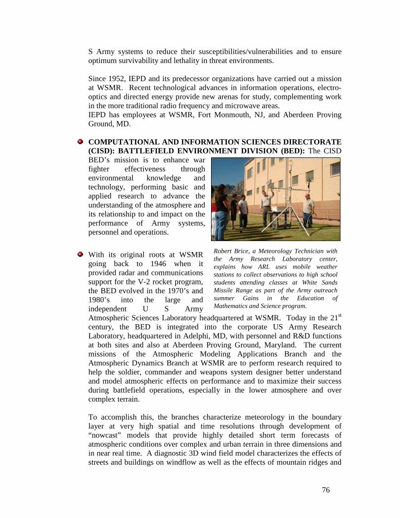
76
S Army systems to reduce their susceptibilities/vulnerabilities and to ensure optimum survivability and lethality in threat environments. Since 1952, IEPD and its predecessor organizations have carried out a mission at WSMR. Recent technological advances in information operations, electro-optics and directed energy provide new arenas for study, complementing work in the more traditional radio frequency and microwave areas. IEPD has employees at WSMR, Fort Monmouth, NJ, and Aberdeen Proving Ground, MD.
COMPUTATIONAL AND INFORMATION SCIENCES DIRECTORATE
(CISD): BATTLEFIELD ENVIRONMENT DIVISION (BED): The CISD BED’s mission is to enhance war fighter effectiveness through environmental knowledge and technology, performing basic and applied research to advance the understanding of the atmosphere and its relationship to and impact on the performance of Army systems, personnel and operations.
With its original roots at WSMR
going back to 1946 when it provided radar and communications support for the V-2 rocket program, the BED evolved in the 1970’s and 1980’s into the large and independent U S Army Atmospheric Sciences Laboratory headquartered at WSMR. Today in the 21st century, the BED is integrated into the corporate US Army Research Laboratory, headquartered in Adelphi, MD, with personnel and R&D functions at both sites and also at Aberdeen Proving Ground, Maryland. The current missions of the Atmospheric Modeling Applications Branch and the Atmospheric Dynamics Branch at WSMR are to perform research required to help the soldier, commander and weapons system designer better understand and model atmospheric effects on performance and to maximize their success during battlefield operations, especially in the lower atmosphere and over complex terrain.
To accomplish this, the branches characterize meteorology in the boundary layer at very high spatial and time resolutions through development of “nowcast” models that provide highly detailed short term forecasts of atmospheric conditions over complex and urban terrain in three dimensions and in near real time. A diagnostic 3D wind field model characterizes the effects of streets and buildings on windflow as well as the effects of mountain ridges and
Robert Brice, a Meteorology Technician with the Army Research Laboratory center, explains how ARL uses mobile weather stations to collect observations to high school students attending classes at White Sands Missile Range as part of the Army outreach summer Gains in the Education of Mathematics and Science program.
77
forest or jungle canopies. Weather decision aids provide planners and operators with intuitive warnings of many types of weather hazards on weapons systems, personnel and operations, and can automatically find the best route for manned and unmanned aircraft around bad weather. Research is performed to characterize, predict and quantify the atmosphere’s effects on high energy laser systems, to extend sensing through the atmosphere into new regions of the EM spectrum such as Terahertz and short wave infrared; and to explore new technologies and techniques such as bio-inspired methods to sense and cope with wind gusts and turbulence for improved environmental awareness by autonomous systems. Products are transitioned to a variety of Army entities and to the US Air Force Weather Agency for support of forward deployed Army and Air Force weather teams. Methods are developed to improve meteorological corrections for artillery accuracy in the Mobile Profiler System development program. Weather impacts and nowcasting are exploited in command and control systems such as the Distributed Common Ground Station-Army (DCGS-A) and the Tactical Airspace Integration System (TAIS).
Learn more about the Army Research Laboratory at www.arl.army.mil.
THE CENTER FOR COUNTERMEASURES: (The Center)*: The Center for Countermeasures (the Center) is a joint activity that directs, coordinates, supports, and conducts independent countermeasure/counter-countermeasure (CM/CCM) test and evaluation (T&E) activities of U.S. and foreign weapon systems, subsystems, sensors, and related components in support of the Director, Operational Test & Evaluation (DOT&E), Deputy Assistant Secretary of Defense (DASD) Developmental Test & Evaluation (DT&E), weapon system developers, and the Services. The Center’s testing and analysis directly supports evaluation of the operational effectiveness and suitability of CM/CCM systems. Specifically, the Center assists the Services in:
Performing early assessments of CM effectiveness against threat and DoD systems and subsystems.
Determining performance and limitations of missile warning and aircraft survivability equipment (ASE) used on rotary wing and fixed wing aircraft.
Determining effectiveness of precision-guided weapon (PGW) systems and subsystems when operating in a CM degraded environment.
Developing and evaluating CM/CCM techniques and devices. Testing new CMs as they are discovered on the modern battlefield in
operationally realistic environments. Providing analysis and recommendations on CM/CCM effectiveness to Service
Program Offices, DOT&E, DASD (DT&E) and the Service member. Supporting Service member exercises, training, and pre-deployment activities.

78
Providing SME input to panels, task forces, program reviews and/or working groups
Services and Products:
The Center supports the Services with:
Open air infrared countermeasure (IRCM) T&E ASE T&E with an emphasis on rotary wing platforms HF data collection and activity coordination Threat injection during pre-deployment events PGW T&E in a CM/CCM environment
Unique capabilities include:
Mobile, self-sufficient T&E equipment that is deployed to any DoD range or
military training facility as required by the sponsor Institutionally funded workforce provides significant savings to the program Independent CM/CCM assessments at any time in the program’s acquisition
cycle T&E Support Areas:
Aircraft Survivability equipment (ASE) Missile Warning Systems and laser warning Directed Infrared Countermeasure (DIRCM) systems Flare and flare sequence development MANPAD live fire test events
Hostile Fire (HF)
Ground truth data measurements, calibration and evaluation Hostile Fire Indication (HFI) T&E methodology and HF database HF modeling and simulation tools
Precision Guided Weapons (PGWs) and Targeting Systems
Foreign obscurants Lasers Captive flight test Camouflage, concealment and deception
Warfighter Integration and Training
Pre-deployment training Exercises and military schoolhouse training support
T & E products:

79
The Center produces the following documents depending on the support requirement to DOT&E and the sponsoring Service Office.
Event Report (ER) – For every event an ER is produced, providing a synopsis of the event and applicable initial findings of the activity (usually a 1-2 page document)
Analysis Report (AR) – Is the compilation of results, analysis and test findings on how the system under test performed in the CM/CCM environment.
Technical Memorandum (TM) – A technical data package, usually without assessment components, for the sponsor.
Process for requesting T & E support:
Requests are submitted to the Center’s Director. A written request must be received from DoD or other U. S. government agency specifying the requested support before the activity begins (ideally, at least 90 days or earlier). The request letter should be addressed to the Director, Center for Countermeasures, 1407 Martin Luther King Jr. Ave, White Sands Missile Range, NM, 88002.
In summary, the Center’s mission is to:
Assist the system developer and the DT and OT agencies in CM/CCM testing Support the Warfighter in preparation for operating in current theaters of
operation and training exercises Provide independent, timely, accurate information and recommendations on
CM/CCM T&E. For More information, e-mail: [email protected]

80
NATIONAL GEOSPATIAL-INTELLIGENCE AGENCY (NGA): The National Geospatial-Intelligence Agency (NGA) at WSMR acquires, analyzes, reduces, and furnishes precise geodetic and geophysical survey data to WSMR support personnel and outside customers. NGA provides astrogeodetic deflections, geoid heights, gravity values, precise distances, true azimuths, astronomical positions/azimuths and geodetic control to accuracies of one part per million. Increased accuracies can be achieved using state-of-the-art equipment and techniques to precisely locate the impact points of missile components and other test debris for flight safety, recovery, and post-test analysis. NGA provides geodetic and Universal Transverse Mercator (UTM) positions based on the World Geodetic System 1984 (WGS84) and mean sea level elevations based upon the Earth Gravitational Model 2008 (EGM08). The mission of the National Geospatial-Intelligence Agency (NGA) is to provide accurate and timely expert analysis of worldwide gravity, satellite and positional information including imagery and mapping control for navigation, safety, intelligence, positioning and targeting in support of national security objectives. The White Sands Missile range NGA Support Team acquires, analyzes, reduces, and furnishes s precise geodetic and geophysical survey information to WSMR Mission partners and other DoD customers outside WSMR. NGA provides ground truth verification for applications such as radar/telemetry calibration, operational test and evaluation, target data for weapons testing as well as various special applications tailored to customer requirements. No one customer requirement is identical to another and are subject to changes, as survey plans are fluid. For more information contact Chief, White Sands Missile Range NGA Support Team, Building 1621, White Sands Missile Range, NM 88002 or call (575) 678-2140

81

82
DIRECTIONS TO WHITE SANDS MISSILE RANGE: The range is located in the Tularosa Basin of south-central New Mexico. The headquarters area is 20 miles east of Las Cruces, New Mexico, and 45miles north of El Paso, Texas. The range boundaries extend almost 100 miles north to south by 40 miles east to west. At almost 3,200 square miles the range is the largest military installation in the country.
TO WSMR MAIN POST FROM EL PASO, TEXAS AIRPORT:
When you leave the El Paso Airport area, turn right onto Airway Blvd At the second stoplight, turn right onto Airport Rd. Airport Rd
becomes Fred Wilson Blvd Immediately after the Fred Wilson overpass, turn right and enter
Highway ramp on the left). Continue on Highway 54 and exit on Martin Luther King Exit 31.
Turn left onto MLK Jr. Blvd. and stay on it (follow the signs that guide you
It is approximately 34 miles from this point to the El Paso Gate entrance WSMR main post area.
After the Cattle Guard, the speed limit drops from 65 mph to 55 mph. At the second Yellow Flashing light, the road makes a 90 degree right
turn speed limit at the turn is 15 mph. Stay on the highway, and the mountain will be on your left hand side.
FROM LAS CRUCES, NEW MEXICO:
Take Highway 25 north to Highway 70 East (Highway 70 is also
called "Main Street”). Turn right onto Highway 70 East towards WSMR or Alamogordo Continue on Highway 70 East for about 25 miles over the San
Augustine exit just after mile marker 169. Turn right onto Owen Rd The Las Cruces/Alamogordo Main Post Gate is approximately 3 miles
after.
FROM ALAMOGORDO, NEW MEXICO:
Take Highway 70 west. Proceed about 47 miles to the missile range exit labeled
"Headquarters" mile marker 172. The exit ramp loops under Highway 70 onto Owen Rd.
The Las Cruces/Alamogordo main post gate is approximately 3 miles.

83

84
VISIT REQUESTS: For U. S. citizens that will be visiting WSMR, all security clearances should be faxed to the WSMR Security Office at 575-678-3157. The Test Officer or other WSMR Point of Contact (POC) will contact this office and the Protocol Office (if applicable) to make them aware of your visit. For Non-U.S. citizens representing a foreign government, industry or academic institution, the following policy applies:
All visits by foreign nationals will require advance notification NLT 15 days and approval by the WSMR Foreign Disclosure Officer (FDO). Although visit requests usually come into WSMR through the DA SPAN network, monitored and processed internally within WSMR by the FDO, other visitors such as Liaison Officers (LNO) or visitors on Invitational Travel Orders (ITO) may come directly to the WSMR POC (normally the WSMR Test Officer (TO)) for the project involved. In such cases, the POC will instruct the potential visitor to submit his request through his local FDO. These occurrences should be identified to the WSMR FDO as soon as possible to ensure proper coordination is made with the other agency involved.
WSMR POC’s sponsoring meetings including foreign national participation will ensure that appropriate visitor clearance is required, whether the meeting is held on WSMR proper or at an off-site location.
All official foreign contacts with the Army must be requested by diplomatically accredited military attaches on behalf of their government. Foreign military attaches are provided with a handbook summarizing policies and procedures contained in AR 380-10.
Except as authorized by the HQDA or senior Army leadership (Secretary of the Army, Under Secretary of the Army, Chief of Staff, or Vice Chief of Staff), foreign representatives are not authorized official contact or communications with either DA personnel or DA organizations in any manner pertaining to any aspect of official business without prior authorization. Foreign representatives initiating such contact are to be informed that appropriate prior authorization for contact must be obtained on their behalf from DA by their respective military attaches.
The Foreign Disclosure Officer (575-679-6353) should be notified as soon as possible as to the dates of the confirmed visits.
VISITING THE RANGE:
Visitors on WSMR are limited to the cantonment area within the Las Cruces and El Paso gates, the housing area and no further than Hughes Road on Nike Road (east of Headquarters Boulevard) except:
When on official business with authorization by the activity being visited, to travel directly to and from that activity.

85
Foreign nationals when on official business accompanied by a military or civilian employee, or by contractor personnel who have unrestricted travel authority to and from activities located outside the main post area. All such escorts must be “Foreign National Escort” trained by the Test Center Foreign Disclosure Officer.
Commercial vehicle drivers will produce a Bill of Lading that indicates the location, agency, or building to be visited. Once verification is completed, a pass will be issued.
Visitors are required to provide their WSMR Point of Contact (POC) name and telephone (land-line preferred) number to assist the Reception Center personnel in verifying visitor’s intended actions as they visit the range.
VEHICLE REGISTRATION: Beginning January 1, 2012, vehicles entering the installation will no longer require installation vehicle registration stickers. Individuals with Department of Defense affiliated identification cards or individuals with RAPIDGate Passes can access the installation without stopping at the Reception Center for a vehicle pass. DOD affiliated personnel will still be able to vouch for visitors. Visitors with no DOD affiliated identification will still be required to obtain a temporary pass for their vehicle when entering the installation. Other Government identification may be approved and authorized on a case by case basis. If a DOD ID card holder is riding in a vehicle not owned by the DOD ID holder, there
will be no requirement for a temporary pass. Personnel who have vehicles that currently have a military registration sticker should remove and destroy the stickers once they expire.
In order to get a pass, the driver will have to show the following items required by the State of New Mexico by all motor vehicle operators:
Valid driver's license Current vehicle registration Current proof of insurance
BADGE REQUIREMENTS: For other entrances, visitors must be able to provide
authorization to be up-Range as is available through their Sponsor’s Security Coordinator. News media representatives are required to be escorted while on range except at events open to the public.
African oryx also known as gemsbok (Oryx gazella) are sometimes seen in
and around WSMR roads.

86
ROADBLOCK INFORMATION: Roadblocks are designed to protect motorists from the unlikely event of missile and target debris falling on the highway during a test mission. As a rule roadblocks last about an hour. They can last longer if there is a problem or if personnel have to clean up debris from the road. The Range sets the following color coded roadblocks on public roads around the installation:
Roadblock information is usually updated each weekday in the late afternoon for the following day. Since Range mission schedules can slide due to circumstances like
weather or equipment problems, local highway and Range travelers should check the recording right before leaving to ensure nothing has changed.
PHOTOGRAPHY RESTRICTIONS: Generally, photography is prohibited; however,
personal photography is authorized without prior permission in the following areas:
North of Martin Luther King Avenue to Highway 70 to include all of Owen Road, except in the area bordered by Headquarters Avenue, Aberdeen Avenue, Dyer Street, and Martin Luther King Boulevard.
West of Headquarters Avenue to the western range boundary, Area south of Nike Avenue to Martin Luther King Avenue east, Headquarters Avenue (otherwise known as Range Road 1 or El Paso
Road) only to 500K access. These areas include the skeet range, JFK Parade Field, Missile Park,
clinic, barracks, and picnic and recreation areas.
All other areas require photo permits. Requests must be signed by an official of a Range or tenant element, and then forwarded to the Directorate of Plans, Training, Mobility & Security (DPTMS) Security Manager for approval. Photography of mission related areas is limited to authorized official WSMR photographers. The absence of an official photographer's permit may result in confiscation of the film and/or photography equipment.
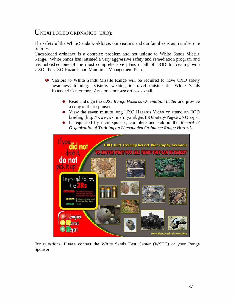
87
UNEXPLODED ORDNANCE (UXO): The safety of the White Sands workforce, our visitors, and our families is our number one priority. Unexploded ordnance is a complex problem and not unique to White Sands Missile Range. White Sands has initiated a very aggressive safety and remediation program and has published one of the most comprehensive plans in all of DOD for dealing with UXO, the UXO Hazards and Munitions Management Plan.
Visitors to White Sands Missile Range will be required to have UXO safety awareness training. Visitors wishing to travel outside the White Sands Extended Cantonment Area on a non-escort basis shall:
Read and sign the UXO Range Hazards Orientation Letter and provide
a copy to their sponsor View the seven minute long UXO Hazards Video or attend an EOD
briefing (http://www.wsmr.army.mil/gar/ISO/Safety/Pages/UXO.aspx) If requested by their sponsor, complete and submit the Record of
Organizational Training on Unexploded Ordnance Range Hazards
For questions, Please contact the White Sands Test Center (WSTC) or your Range Sponsor.

88
EXTENDED CANTONMENT AREA
INSTALLATION HOURS OF OPERATION: WSMR personnel are here to serve your testing needs. Based on your testing priorities, we will strive to meet your requirements on weekends and holidays as needed. Core working hours are from 0800 to 1630 Monday thru Friday. Mission objectives may require shift work in which working hours are adjusted outside of the normal core hours to support your needs. WSMR has an annual Range Shutdown period for specific maintenance that encompasses the Saturday before Christmas through the Saturday after New Years.
SMOKING POLICY: Smoking is prohibited inside all government facilities and vehicles at White Sands Missile Range. Smoking is permitted only in established designated areas and only in accordance with laws and current regulations. Smoking is allowed at a distance of at least 50 feet from government buildings.
89

90
FAMILY & MORALE, WELFARE AND RECREATION (MWR):
The Garrison Command’s Family & Morale, Welfare, and Recreation organization would like to welcome you to our community. F&MWR offers a wide variety of recreational activities, hobby opportunities, innovative events and social gatherings for the White Sands community. If you enjoy golf, bowling, or skeet shooting, F&MWR can help you. F&MWR also offers top quality child care and youth programs, discount tickets to area attractions, arts & craft classes and much, much more!! F&MWR is also committed to providing support and leisure services that are as outstanding as the people that we serve. We believe that Soldiers and their Families deserve the same quality of life as they are pledged to defend. F&MWR encourages the healthy balance of work and leisure that Soldiers need, by delivering state of the art facilities, community event tickets, holiday functions, competitive and recreational sports, family support services. F&MWR is for the entire military population, including Active Duty, Reserve, National Guard, Retirees, DoD Employers, Contractors, their Spouses and Families. Additional information for all services can be found in the appendix. Some of our major services are listed below:

91

92
LAUNDROMAT Building 436
(575) 678-3270 Coin-Operated Open 24 Hours
MAIN EXCHANGE Building 260
(575) 678-2498 Mon-Fri 1000-1900
Sat 1000-1700 Sun 1000-1500
SERVICE STATION Building 270
(575) 678-4877 Mon-Sat 0600-2100
Sun 0800-2000
SHOPPETTE
(575) 678-0248 Mon-Sat 0600-2200
Sun 0800-2000
F & MWR QUICK REFERENCE MAP
F & MWR QUICK REFERENCE LIST
Aquatics Center, Bldg 462, (575) 678-1068/1341 Army Community Service, Bldg 250, (575) 678-6767 Arts and Crafts Shop, Bldg 426, (575) 678-5321 Auto Skills Center, Bldg 1430, (575) 678-5800 Bowling Center-Roadrunner Lanes, Bldg 234, (575) 678-3465/(575) 678-1394 Business and Recreation Division, Bldg 501, (575) 678-6105 Community Activities Coordinator (MWR), Bldg 501, (575) 678-1256 Community Center, Bldg 460, (575) 678-4134 Community Center, (ITR Office), Bldg 460, (575) 678-4134 Frontier Club, Bldg 1330, (575) 678-2055/(575) 678-2057 Golf Course Pro Shop, Bldg 1330, (575) 678-1759 Lodging Operations, Bldg 501, (575) 678-4559 Outdoor Recreation, Bldg 445, (575) 678-1713 Gymnasium Office, Bldg 236, (575) 678-3374
ARMY AND AIR FORCE EXCHANGE SERVICE (AAFES): AAFES strives to provide optimum customer satisfaction with emphasis on customer service. Their mission is to provide quality goods and services at competitively low prices and generate earnings to support MWR activities. AAFES operates the following facilities at WSMR:

93
MOUNTAIN VIEW CAFÉ Building 120
(575) 678-2081 Mon-Fri 0700-1300
Closed weekends, holidays, and compressed Fridays
THEATER Building 254
(575) 678-2483 Fri, Sat & Sun 1900 Mon-Thu – Closed
www.aafes.com/ems/conus/whitesands.htm
FAMILY HAIR CARE Building 260
(575) 678-2040 Mon-Fri 0900-1700
Sat 0900-1400 Sun – Closed
USPO, WSMR Building 153
Rock Island Street White Sands Missile Range
New Mexico 88002 (575) 541-7429
HOURS OF OPERATION: Mon 1100-1300, 1400-1600 Tue – Fri 1000-1300, 1400-1600
SPECIAL HOURS AFTER MONDAY HOLIDAY:
Tue 1100 – 1300, 1400-1600 Wed – Fri 1000-1300,1400-1600
WHITE SANDS POST LIBRARY
For additional information about library services call or go online at:
(575) 678-5820; DSN 258-5820 http://www.wsmr.army.mil/garrison/dir/hr/ace/Pages/PostLibrary.aspx
HOURS OF OPERATION:
Thursday – Sunday 0900 – 1600 Closed Holidays
UNITED STATES POST OFFICE: A full service post office is located in the WSMR main Post area.
INTERNET ACCESS: The White Sands Post Library provides 18 computers with internet access and is set-up for wireless usage. Key codes are provided at the front desk for computer usage. Computers may be used for research and personal use. The Library is located in the Professional Development Center in Building 465. In addition to the computer inventory, the Library houses over 48,000 fiction and nonfiction titles, subscriptions to 55 magazines, audio books, and a wide variety of other items that may be checked-out or used in-house. New titles are regularly added and reference material is continuously updated. The Technical Section contains an extensive assortment of manuals, technical papers, and books.
TELEPHONE: White Sands Missile Range maintains a complex telephone network and operations system infrastructure supported with extensive platform expansions and network communications. Information on telephone services is available at (575) 678-2121 or operator assistance is available by dialing “0” from an on-post number.

94
Official telephone service is provided solely for transacting official government
business and is available to all organizations and contractors designated as official. Official government users are referred to as Class Al and official government Contractors are referred to as Class A2. All official telephones have access to 800 long distance numbers and specific phones have access to commercial overseas numbers.
Three-way conferencing and call transfer is furnished. Other features such as call waiting, speed calling, call forwarding, are available. Conference calls, also known as “meet me” lines may be arranged for accommodating up to thirty parties. These calls may include a combination of WSMR, DSN, government or commercial long distance numbers. Dial "0" for the WSMR operator, provide the names and numbers needed, and the operator will establish the call for you. To add to an existing conference call, the initiator of the call should press and release the receiver button on the set, and the operator will answer. Please remain on the line while the call is being established.
CELL PHONE USAGE: Vehicle operators on a DoD Installation and operators of Government owned vehicles shall not use cell phones unless the vehicle is safely parked or unless they are using a hands-free device. The wearing of any other portable headphones, earphones, or other listening devices (except for hands-free cellular phones) while operating a motor vehicle is prohibited. Use of those devices impairs driving and masks or prevents recognition of emergency signals, alarms, announcements, the approach of vehicles, and human speech. DoD Component safety guidance should note the potential for driver distractions such as eating and drinking, operating radios, CD players, global positioning equipment, etc. Whenever possible this should only be done when the vehicle is safely parked. Cell phones are prohibited from usage in Building 335, the Cox Range Control Center.

95
WHITE SANDS MISSILE RANGE
DIALING TABLE WHITE SANDS MISSILE RANGE (WSMR) POST LOCATOR LOCAL AREA ON-POST LOCAL CALLING AREAS DSN FOR INCOMING CALLS LOCAL AREA OFF-POST ALAMOGORDO, NM EL PASO, TX FT BLISS, TX HOLLOMAN AIR FORCE BASE, NM LAS CRUCES, NM SOCORRO, NM WILLIAM BEAUMONT ARMY MED CTR DSN FOR OUTGOING CALLS TOLL CALLS (CHARGES APPLY) DIRECT DIAL NEW MEXICO INFORMATION OPERATOR ASSISTED / COLLECT OUTSIDE NEW MEXICO INFORMATION OVERSEAS INFORMATION OPERATOR FT BLISS, TX HOLLOMAN AFB, NM WSMR AREA TELEPHONE SERVICES HELP DESK NON-EMERGENCY POLICE EMERGENCY NUMBERS AMBULANCE/ FIRE/ MILITARY POLICE PUBLIC PAY PHONE LOCATIONS BARRACKS COMMISSARY MAIN POST EXCHANGE ROADRUNNER LANES/BOWLING CNTR
AREA CODE (575); DEFENSE SWITCHED NETWORK (DSN) 258 0 or (575) 678-2121 678-XXXX; 679-XXXX; 674-XXXX 258-XXXX; 349-XXXX 99 + XXX-XXXX 98 + XXX-XXXX 98 + 568-XXXX, 98 + 569-XXXX 99 + 572-XXXX 99 + XXX-XXXX 99 + XXX-XXXX 98 + 568-XXXX 94 + XXX-XXXX 99 + 1 + AREA CODE + XXX-XXXX 99 + 1 + 411 99 + 0 + AREA CODE + XXX-XXXX 99 + 1 + AREA CODE + 555-1212 99 + 0 + 1 + country code + city code + phone number 98 + 568-2121 99 + 572-1110 678-2121 or 0 or 114 678-1621 or 678-1111 678-1234 678-1234 or 911 Bldg 128 (1st Floor, West End) Bldg. 262 (Front of Bldg) Bldg 260 (Front of Bldg) Bldg 234 (Hallway)

96
White Sands Missile Range Area Map

97

98

99

100

101
AIRSPACE APPENDIX:
GENERAL POLICY: Airspace available for range missions consists of various restricted areas, which require up to 12 hours notice to the Federal Aviation Administration (FAA), Albuquerque Air Route Traffic Center (ARTCC).

102
Scheduling of range airspace is normally identified by utilizing the White Sands Grid Map, which uses letters for east/west areas and numbers for north/south areas. Adding the specific restricted areas in the pattern block of the scheduling form further identifies airspace needs. Planned use of Holloman Air Force Base areas (R-5107D) should be avoided between Q-T 24-50, to lessen impacts to routine flight operations. Flights that require Holloman airspace shall be above 15K when East of the “Quebec” line between 24 – 50, which will permit routine flight operations at the airfield. The Holloman airspace (R-510D) is subdivided into five areas which require 12 to 72 hours notice for recall for range support. For those missions which require airspace east of the “Quebec” line below 15K, must identify the grid coordinate and airspace in the appropriate box on the scheduling form. Utilization of Fort Bliss Airspace, R-5103 A/B/C and R-5107A/K, is coordinated by the Range Scheduling office. Ideally, thirty days advance notice is expected, but may be coordinated seven days prior to use, dependent on Fort Bliss requirements. Flights which will exceed the boundaries of restricted airspace shall be coordinated with the FAA, Albuquerque ARTCC, at least thirty days in advance or as soon as the requirements are made known. This is normally accomplished through Range Control Airspace Management Office. A comment in the remarks section of the scheduling form is needed to identify this requirement to range control and Cherokee control for day of test information. This coordination does not relieve the aircraft pilot(s) from filing appropriate flight plans for the area of operation. The lowest altitude for routine flight operations shall be 1,500 feet above ground level (AGL) to provide airspace for under flight of helicopters in support of range missions, unless to the “surface” is required. If flight below 1,500 ft AGL is required, it shall be identified as “surface to (needed altitude) in the altitude block of the scheduling form. In order to provide access to the air-to-surface ranges of the 49th WG, all aircraft when north of the 54 line shall be at or above 16,000 ft mean sea level (MSL) when east of the “PAPA line.” Missions requiring this airspace below 16,000 MSL shall be identified as “surface to (needed altitude) in the altitude block of the scheduling form. Unless specific “safety ceilings” are published by the Flight Safety organization, no over flight of Hot Missions (Firings) or Unmanned Target Missions shall be authorized. The scheduled aircraft start time is defined as the initial entry into the scheduled airspace per the range schedule. Aircraft entering the range from an off station location should expect a transfer of communications from the Controlling Air Traffic Control (ATC) facility to Cherokee Control prior to the range boundary. Aircraft departing from Holloman Air Force Base (AFB) shall coordinate the departure time and/or route via the Holloman Approach Control, who in-turn will coordinate the routing with Cherokee Control. Aircraft which may arrive early should expect to hold outside the range boundary until the airspace is available. The scheduled complete time is defined as the time the aircraft exits the range boundary per the range schedule. Aircraft shall be returned to Cherokee Control at least five minutes prior to the scheduled completion time in order to be off range as published.

103
This permits time to coordinate the route with the appropriate ATC facility. If airspace is required prior to the arrival of an aircraft, launch of a rocket, missile, artillery, or ground detonation, it shall be identified in the time line when the airspace protection is needed. No aircraft shall enter the airspace scheduled by another test mission without the approval of both test mission managers. This request shall be coordinated with range control at least thirty minutes in advance or as soon as practical on short notice. FLIGHT RESTRICTIONS:
National Wildlife areas: Voluntary over flight of 2,000 feet above ground level (AGL) is recommended over the grid coordinates for: San Andres area K- N 23-34, Bosque Del Apache G - J 63-73, and Sevilleta H - M 82-90.
Aerial Cable area: No flight below 9,000 ft MSL over N-P 62-64 unless prior
coordinated through range scheduling or identified in the Operational Document.
No flight below 7,500 MSL and avoid laterally 3,400 feet over the buildings
located between N-O 16-17.
Any other restrictions as identified on the published range schedule to ensure separation from other range missions.

104

105
TRAINING MISSIONS APPENDIX: WSMR has many years of experience in planning and execution of training missions. Examples of training missions that WSMR has supported include:
Roving Sands (world’s largest multi-national air and missile defense exercise) Air Force tactical flight training and exercises NASA shuttle pilot training future force exercises Joint interoperable and live-virtual-constructive applications
Training exercises are used to establish warfighter readiness. The expansive WSMR terrain is prime location for warriors from all military services to be exposed to a variety of exercises including theater air and missile defense; joint forcible entry operations; joint medical evacuation; logistics; operational area planning, coordinating and execution; aircraft “enemy” targets; situational awareness; long and short range air defense; defense strategy development; threat intelligence; air and ground defense; synthetic battlefields; fielding new hardware; and combined maneuver and live fire unit training. The following policy (WST 385-1) has been prepared for customers that will be using the Range for training missions: TEDT-WSTC MEMORANDUM FOR SEE DISTRIBUTION SUBJECT: Policy for Training Conducted on White Sands Missile Range (WSMR) 1. PURPOSE. This policy assigns responsibilities, provides guidance and establishes policy and procedures for training conducted at range areas and facilities located on WSMR. It will ensure that the White Sands Test Center (WSTC) and Garrison planners, operators and users integrate safety and risk management into the design, use, and execution of training missions to enhance combat readiness, eliminate injuries, and avoid property damage. 2. SCOPE. a. This policy applies to all training activities conducted on WSMR. However, the following exceptions apply: (1) New equipment training (e.g., during limited user testing or Operational Testing and Developmental Testing) as specified in AR 350-1 or Research Development Test and Evaluation programs.

106
(2) Users of Morale Welfare Recreation (MWR) Skeet Range or recreational areas. (3) The US Army Garrison (USAG) Plans, Training, Mobilization, and Security (DPTMS) small arms range when utilized In Accordance With (IAW) paragraph 2.a. (1), 2.a. (2). (4) Services training on Red Rio, Oscura Range Complex, Lava East/West, Mesa East/West, Yonder, Yonder West, Yonder South. Users of these ranges will comply with an established Letters of Agreement (LOA) and the Holloman AFB Comprehensive Range Plan as it applies to the training areas. Refer to paragraph 6.f., for unit commanders’ responsibilities. 3. REFERENCES. See Appendix A. 4. DELEGATION OF AUTHORITY.
a. WSMR Commanders/Directors have not been given delegated authority to deviate from the provisions of this policy, unless authorized by the reference publications in Appendix A or other publications which are established to operate training ranges or exercise areas. b. Waivers/Deviations regarding training at WSMR with high risk, exceeding the local unit commander’s authority, will be submitted to the WSMR Commander through the commander having Training Readiness Authority (TRA) for approval/disapproval. 5. POLICY. a. The WSTC Range Operations (RO) Directorate is the installation Operational Range Control Organization. b. Due to the extensive use of range facilities on WSMR and the overlying airspace, live fire training and maneuver range activities will be coordinated/schedule through WSTC RO. c. Development of new training area(s) or operational changes to established training areas will be IAW Department of the Army regulations. Requests for establishing new training ranges and areas shall be submitted to USAG-DPTMS, who will coordinate with WSTC for possible impacts. d. Range users will ensure their activities are planned and conducted IAW range safety, environmental and range operational standards. e. Sponsors of Special Operation Units will ensure that Director of RO and the WSTC Commander are briefed on the operations to be conducted.

107
f. All training will only be conducted in the approved training locations on WSMR. g. Organizations conducting training on WSMR will comply with WSMR’s safety procedures and must follow their service approved training plans/POI, syllabus, flight and ground safety policies and procedures. h. Training plans must be approved and signed by the training unit commander before being submitted to WSMR for review/comment. (1) The unit will submit their training plan to RO for review coordination and schedule. (a) RO will coordinate safety reviews with Installation Safety. (b) RO will coordinate environmental reviews with WSTC and USAG environmental. (2) Conflicts regarding level of risk determination will be resolved by the commander having TRA authority for the highest level of risk. i. Joint service training events such as Roving Sands will be managed by a range sponsor. Planners will ensure compliance with the appropriate service regulations and this policy. j. Scheduling Procedures: All training exercises and live fire operations conducted on WSMR will be coordinated and scheduled IAW RO Scheduling Policy. (1) New Mexico Army National Guard small arms training ranges near Mine Site must follow their established Standard Operating Procedures (SOPs) and WSMR procedures. (2) Units performing convoy operations from garrison locations using tank trails or roadways that transition through the WSMR range area will coordinate convoy movements with RO, Range Control Branch (RO-CR) at least 24 hours in advance. Coordination will ensure commanders are aware of range activities that could impede unit movement. (3) DPTMS small arms ranges are considered operational when identified on the schedule. k. Electronic equipment emitting radio frequencies (RF) will follow the established WSMR procedures for such devices. l. Officer In Charge (OIC) and/or Range Safety Officer (RSO) will follow the established communication procedures as prescribed in DA PAM 385-63, TC 25-8 and range SOPs.

108
m. Incident/Accident Reporting will be submitted in accordance with the Department of the Army Regulations and WSMR Commanding Generals Commanders Critical Information Requirements (CCIR) Policy. 6. RESPONSIBILITIES. a. Director, Range Operations will: (1) Appoint a Range Engineer (RE) for each training range/facility that is located outside the main cantonment area. (2) Appoint an Installation Range Control Officer (RCO). For WSMR, the RCO is RO-CR Branch Chief or his designated representative. b. The RCO will: (1) Serve as the central point for coordination. (2) Ensure Range Control personnel are appropriately trained to monitor training activities.
c. Garrison Commander:
(1) Ensure Garrison sponsored training occurring on WSMR Test Range is coordinated and scheduled with RO.
d. Director, WSMR Installation Safety Office will:
(1) Ensure compliance with procedures established in AR 385-63 and DA Pam 385-63.
(2) Ensure areas designated for training are safe for use, and authorized for the
proposed training. (3) Ensure OIC and RSO are certified by unit commanders to oversee training
operations. (4) Ensure that commanders of training units have evaluated their unit’s
readiness to safely execute the tasks/operations proposed for training. e. Quality Assurance Specialist, Ammunition Surveillance (QASAS) shall monitor all live fire training areas to provide technical assistance and support on ammunition quality and explosive safety matters. QASAS from USAG or WSTC will participate in live fire training range development and planning meetings, assign personnel to training ranges during live fire exercises, ensure units are properly briefed prior to the commencement of

109
training exercises, conduct ammunition malfunction investigations, and conduct range inspections to ensure ammunition is properly maintained. f. Unit Commanders: (1) Ensure all training and exercises are conducted IAW operational standards, applicable service directives, and this policy. (2) Adequately plan for all training and exercise events. (3) Ensure that training exercises are consistent with their unit Mission-Essential Task List (METL). (4) Exert appropriate command and control over unit personnel and training operations. Commanders are responsible for their unit's performance and actions while training on WSMR. 7. My point of contact for this policy is [White Sands Test Center Operations Office], Test Center Commander [(575) 678-1959]. DAVID L. MANN Brigadier General, USA Commanding DISTRIBUTION: A

110
Policy for Training Conducted on White Sands Missile Range (WSMR) Memo APPENDIX A
REFERENCES
AR 75-1, Malfunctions Involving Ammunition and Explosives, 23 April 2001 AR 200-1, Environmental Protection and Enhancement, 13 December 2007 AR 200-2, Environmental Analysis of Army Action, Final Rule, 29 March 2002 AR 350-1, Army Training and Leader Development, 3 August 2007 DA Pamphlet 350-38, Standards in Weapons Training, 16 August 2004 AR 385-10, Army Safety Program, 23 August 2007 AR 350-19, Army Sustainable Range Program, 30 August 2005 AR 385-63, Range Safety, 19 May 2003 DA Pamphlet 385-63, Range Safety, 10 April 2003 DA Pamphlet 385-64, Ammunition and Explosives Safety Standards, 15 December 1999 DTC 385-1 Safety Training Conducted at Ranges, Controlled by DTC Test Centers, 27 February 2007 FM 5-19, Composite Risk Management, 21 August 2006 FM 7-0, Training the Force, 22 October 2002 Holloman Air Force Base, Comprehensive Range Plan, 20 February 2007 Letter of Agreement, Tri-Service Aviation Training Operations on WSMR, 22 April 2005 TC 25-1, Training Land, 15 March 2004 TC 25-8, Training Ranges, 5 April 2004
111
GROUND SAFETY APPENDIX: PROCEDURES: The WSMR Director, Installation Safety Office, or his representative, may be present at each ground launch. He will coordinate his activities with the Project Safety Officer; however, his presence or absence in no way affects the safety responsibilities of those conducting the launch. SAFETY STANDING OPERATING PROCEDURE (SSOP): A SSOP for all tests presenting a hazard to personnel or materials should be submitted at least 10 work days prior to first test. Hazardous operations are defined as, but not limited to, operations involving explosives, ammunition, highly flammable or toxic products, radioactive material, high-pressure gases, microwave radiation or lasers. The SSOP must contain detailed operating instructions for each operation and describe all safety measures. These safety measures include, but are not limited to, protective clothing and equipment, monitoring devices, requirements for static grounding, special handling and disposition requirements or any other safety requirement peculiar to the operation. Previously developed operating instructions, technical publications, engineering orders and similar procedures which are acceptable to the WSMR Safety Director may be used in the operating instructions. When such publications are used, the titles and applicable portions should be identified and attached to the SSOP. Instructions for preparing the SSOP, including sample format, are provided in WSMR Regulation 385-18. Additional radiological health and safety requirements are identified in WSMR Regulation 40-8 and WSMR Regulation 40-9.
CERTIFICATION OF HAZARDS: The type and magnitude of all hazards must be reported on a STEWS-NR-P Format 1. If testing is conducted using various configurations, the format is required for each configuration with different hazards. Paragraph 1810 of the Operations Requirements document must include explanations to help WSMR evaluate the hazards. When new hazards develop in existing programs, a new hazards format must be provided at least 10 workdays before the first test.

112

113
FLIGHT SAFETY APPENDIX: SAFETY POLICIES AND APPROVALS: This chapter describes the policies and procedures for unmanned flight. It outlines safety principles, requirements and operational controls. Per DoD Directive 3200.11 (“Major Range and Test Facility Base”) and DODI supplement 3200.18 (“Management and Operations of the Major Range and Test Facility Base”), the Commander, White Sands Missile Range (WSMR), is responsible for unmanned flight safety on WSMR. This includes all test activities that originate from, and are flight tested within areas under the Commander’s purview. There are no provisions for transferring this responsibility to the Range Customer or to another range. The Flight Safety Branch of the Operations Control Division under the Range Operations Directorate establishes and manages the unmanned flight and laser beam safety programs for the Commanding General/Installation Director. Flight Safety prepares and implements all policies and procedures associated with the flight safety management for each test program. This includes the approval of flight profiles, ensuring flight and laser beam safety management, and the approval of flight and laser beam termination systems used at WSMR. Flight Safety is made up of two sections: the Flight Safety Analysis Section and the Flight Safety Engineering Section:
The Flight Safety Analysis Section conducts detailed safety assessments for tests, defines the requirements for other Range elements that support the safety management of a test, and produces safety planning documentation. The section determines the levels of risk associated with unmanned flight tests and laser beam operations and has approval authority for testing. The section also determines whether or not a flight termination system, a laser beam termination system, or a flight management system is required for testing. During real-time testing, the analysis section provides operational safety management.
The Flight Safety Engineering Section is responsible for flight and laser beam
termination system performance criteria and final approval of the system. Section personnel maintain positive operational control of all flight and laser beam termination systems throughout the systems’ life cycles. The section also designs, procures and fabricates termination support systems. While working closely with Project and contractor personnel, section personnel ensure that development, qualification, certification, and operations of flight and laser beam termination systems comply with existing Range policies and requirements.
GENERAL POLICY: All tests involve some level of risk and that risk must be minimized. Prudent and reasonable steps must be taken to minimize the level of risk associated with the

114
performance of a given test. However, national defense urgency, costs and test program objectives are considered. Risk for the general public and mission essential personnel are defined in the Range Commanders Council (RCC) Standard 321 “Common Risk Criteria for National Test Ranges” and 321 Supplement. The 321 Standard also defines lethality criteria for unprotected and sheltered personnel, as well as debris damage thresholds for aircraft and ships. Coordination with WSMR Flight Safety should be done as early as possible, preferably during Request For Proposal (RFP) development. To minimize the costs of implementing safety requirements, flight safety data requirements, termination system design, and flight safety funding must be considered early in the development of the program. Flight safety personnel are available for assistance during system development to reduce problems during test phases. Flight Safety personnel should attend all preliminary and critical design reviews and should be given all preliminary design information. This ensures that personnel can identify any potential problem areas or concerns and recommend modifications prior to critical design initiation. Some test items are sufficiently hazardous that a flight termination system (FTS) is required to ensure the items can be contained within controlled areas of the Range in the event of vehicle failure. In coordination with the Project, Flight Safety typically defines the FTS concept and has final approval authority for the FTS. FTS systems will comply with the latest version of the RCC Standard 319 titled, “Commonality Standard for Flight Termination Systems”. Test items, whose entire trajectory and ground impact footprints (including results of malfunctions and impact dispersions) that do not exceed WSMR boundaries or endanger on-range sensitive areas, normally do not require an FTS. All other test vehicles normally do require an FTS. All UAV systems at WSMR are required to have some form of flight management system (FMS). This FMS must be well characterized, verified during pre-mission operations, and must be approved by Flight Safety. Some UAV systems, however, may be required to have a traditional, certified FTS system. Just like other systems in which a FTS is required, the UAV FTS system will have to comply with the latest version of RCC Standard 319, Commonality Standard for Flight Termination Systems. The requirement whether or not a UAV system requires an FTS to be installed will be determined on a case-by-case basis and is further discussed in the latest version of Flight Safety’s UAV Policy. Copies of the policy may be obtained from Flight Safety. All tests involving unmanned flight or laser beam propagation must be approved by Flight Safety. Approval is based upon the analysis of all hazards. After approval to test, if a program fails to maintain safety standards, approval to test will be revoked until the unsafe conditions are corrected. Deviations from safety requirements may sometimes be necessary to meet test objectives. Waivers may be granted if test objectives are sufficiently important to justify the added risk or if national defense objectives cannot be satisfied by other means. The project

115
must provide a written request for a waiver of safety requirements. The approval level for waivers or deviations depends on the extent and risk associated with the request. Initiating the FTS or FMS as a common practice in order to ensure a nominally performing vehicle remains within WSMR controlled areas, will not be allowed. If this practice is required to accomplish a test at WSMR, a waiver must be requested by the project and final approval/disapproval will be provided by the Commander through Flight Safety. Vehicle systems that require an automatic destruct or termination, in order to safely manage the test vehicle, must be approved by the WSMR Commander. This applies to onboard or ground-based systems such as a Ground Based Auto Destruct (GBAD). Redundancy is required for equipment or systems that are critical to the safety management of test operations. This can include equipment and systems that are both on the ground or onboard the test vehicle. REAL-TIME SAFETY MANAGEMENT TRACKING: SYSTEMS REQUIRING FLIGHT TERMINATION SYSTEM (FTS): At a minimum, two independent, certified tracking sources are required during a real-time operation for vehicle systems that require an FTS, FMS, or recovery system. The exception to this rule might be a UAV system that has reached a sufficient developmental maturity level as defined by Flight Safety’s UAV Policy. The Inertial Measurement Unit (IMU) or Global Positioning System (GPS) from the test vehicle may be considered as a tracking source. Positional information available at the UAV’s ground control station (GCS) may also be considered. For any of these systems, they must be well characterized, verified during pre-mission operations, and verified against Range tracking radars (if available) during flight. A tracking aid, such as a radar transponder, may be required to improve data quality. If tracking radars are not available or are not part of the safety management of the test, the IMU and/or GPS will be required to be certified according to the RCC Standard 342 “Global Positioning and Inertial Measurements Range Safety Tracking Systems Commonality.” Primary tracking for flight safety management must be from WSMR-provided sources unless specifically authorized and/or waived by the Commander. SYSTEMS NOT REQUIRING FLIGHT TERMINATION SYSTEM (FTS): Vehicle systems that do not require an FTS, normally do not require real-time tracking support by Flight Safety. However, Range Control or other WSMR entities may require tracking of the vehicle to verify impact within approved areas and/or to assist in test item recovery. In the case of UAV’s real-time tracking support may be required to ensure the UAV’s safe co-use of WSMR controlled airspace with other vehicles.
OFF RANGE LAUNCH & FLIGHT CORRIDORS: Flight corridors over non-WSMR-controlled land and airspace must be evaluated on a case-by-case basis and

116
determined as safe after an extensive risk assessment. Approvals must be obtained from the Commanding General, and coordination with other outside agencies, such as the Federal Aviation Administration, Bureau of Land Management, Forest Service, etc., is typically required. Therefore, early coordination with Range Operations Directorate (RO) is necessary. Test debris (boosters, shrouds, etc.) impacts on public or private land may be planned if a negotiated agreement exists with the landowner; however, early coordination is required
FLIGHT TERMINATION REQUIREMENTS: The Flight Safety Officer (FSO) of the Analysis Section is responsible for flight termination. Flight termination is normally required when:
Data indicates that the test vehicle poses a threat to sensitive areas or the Range boundaries.
Erratic test vehicle performance in which continuation of the flight serves no useful purpose or may cause vehicle damage.
Any possibility of loss of flight termination capability exists even though the vehicle poses no immediate hazard.
Test vehicle performance or position is unknown. Position data of all flight test vehicles is required at all times.
Data indicates the health and status of an existing FTS, FMS, or recovery system is abnormal or unknown. This indicates the possible loss of flight termination capability. Flight termination in this situation may occur even though the vehicle poses no immediate hazard.
Coordination with Flight Safety during the test planning stages is essential to ensure debris impacts within approved areas. All lethal debris from test events must impact within WSMR-controlled land and airspace. If required, non-lethal debris can impact off-range within designated areas only and after a completed risk assessment has been approved.
Test scenarios must be planned so that normal flight and impact dispersion areas do not endanger on-range sensitive areas. Impacts will not be planned for areas in WSMR referred to as “No Use Areas” such as White Sands National Monument.
FLIGHT TERMINATION SYSTEM REQUIREMENTS: All flight termination systems must fully comply with the policies and guidelines defined by Flight Safety personnel. In addition, all airborne flight termination systems hardware packages shall comply with the latest version of RCC Standard 319, Commonality Standard for Flight Termination Systems. Flight Safety personnel will work with each program to ensure that all policies and requirements regarding the FTS are incorporated and completed. Electronic copies of RCC 319 as well as any of the other documents referenced in this chapter can be requested from the Secretariat, Range Commanders Council, White Sands Missile Range.

117
FLIGHT SAFETY INFORMATION REQUIREMENTS: The time required for flight safety planning varies according to the program’s complexity. The importance of early coordination cannot be overemphasized; therefore, customers are highly encouraged to meet with Flight Safety personnel early in the planning stages to discuss data and safety requirements. In some cases, flight safety requirements may even affect the design of the system and early coordination should be achieved years in advance before testing at WSMR. It is also recommended that customers create a Flight Safety Engineering Working Group to meet at regular intervals to work out the safety requirements and to resolve any flight safety issues. The required data is used to conduct appropriate safety and risk analyses to support the test program. From the results, Flight Safety will define evacuation areas, risk to manned sites, and define instrumentation, display, and communication requirements to support the test in real-time. The data requirements discussed below are considered general requirements that could apply to most test programs. Flight Safety will provide a Data Requirements Letter specifically tailored for each program so that only the data requirements applicable to that program are addressed. The exception to this rule is a UAV system. The generic data requirements for a UAV system as well as further discussion concerning UAV’s are defined in Flight Safety’s UAV Policy. The information below will only address a missile and/or rocket-type system(s). SYSTEM DESCRIPTION: SYSTEM PHYSICAL DESCRIPTION: Include the physical dimension, shape and weight of the overall vehicle as well as each stage, the warhead, and payload. Also include an inboard profile drawing showing the location of FTS components. Identify all debris (dome closures, shrouds, interstage structures, etc.) resulting from a nominal test. Again, include the physical dimension, shape and weight of each piece. Include the physical description of the launcher and the launch interface equipment. SYSTEM FUNCTIONAL DESCRIPTION: Identify all vehicle events from pre-launch through intercept and/or impact. The description should include pre-launch verification and preparation procedures, critical timelines, motor ignition sequences, etc. A description of the guidance system to include all operational modes from pre-launch through target intercept and/or impact is required. If the system uses an onboard inertial type navigation system, such as an Inertial Measurement Unit (IMU) or merged IMU/Global Positioning System (GPS), include a detailed description of the system. This description should include the type, drift rates, time navigation starts relative to launch, and parameters available for monitoring the system by telemetry. Selected telemetry parameters from the IMU

118
and/or GPS system may be required to be monitored in real-time as a safety tracking data source. A description of the on-board telemetry system including a telemetry list and the information for processing telemetry data is required. A Hardware-in-the-Loop (HWIL) tape and Calibration Identification (Cal ID) tape will typically be required to allow the Range to verify its data processing and display configuration to support a mission in real-time. A HWIL tape shall be representative of the actual flight and exercises various telemetry functions. The Cal ID tape individually exercises telemetry analog and discrete displays. Specific requirements for generating the Cal ID and HWIL tapes will be provided by the Telemetry Data Center (TDC). A description of the proposed FTS for recovering or terminating the vehicle is required. Tables and/or graphs of Mach vs. Coefficient of drag or ballistic coefficient, imparted velocities and directions for all pieces resulting from a termination action are required. The kinetic energy of each of the debris pieces at ground impact should also be included. If the test vehicle includes a warhead, the effect of flight termination on the warhead must also be included in the description. If the system employs some sort of abort system, such as a parachute recovery system or fuel cut-off, this should also be described. For UAV systems with a FMS, a full description of that system should be included. Further details concerning the UAV data requirements are described in Flight Safety’s UAV Policy. For systems with a live warhead, a functional description of the warhead is required. The description should include the arming method, how the warhead is detonated, and the results of detonation (fragmentation, submunition dispense, etc.). This must also include the ejection velocities of any debris pieces generated as well as their mass, size, shape, material make-up, etc. A description of hang fire and misfire conditions is required. Include how to determine the status of the system and how to return the system to a safe condition. A hang fire is defined as the case where a voltage has been applied to the firing initiator circuit and a misfire is the case where launch has been attempted, but it has been positively determined that no voltage has been applied to the firing initiator circuit. If a misfire cannot be positively confirmed, a hang fire condition will be assumed, which could delay lifting of roadblocks.
TRAJECTORY INFORMATION: A nominal trajectory simulation at true 20Hz and true 1Hz rates from liftoff to impact is required. Coordinate with Flight Safety for proper format. Additional trajectory simulations should also include expected three-sigma in-flight variances in both the lateral and pitch planes. The variances are those that are considered to be caused by normal engineering variances, thrust misalignments, hot/cold motor conditions, etc.

119
VEHICLE FAILURE MODES AND PERFORMANCE CHARACTERISTICS: Maximum energy footprints (which assume no FTS action) based upon total system energy must be generated. This should define the maximum distance a vehicle can travel in any direction, given all possible failure modes and should take into account the lethal area of the warhead if applicable. Over-the-shoulder capabilities should especially be considered as part of the maximum energy envelope. If the vehicle does not have an FTS, the final decision to fly without an FTS will be made only after the maximum energy footprints have been analyzed by the analysis section. Provide the maximum maneuver capability of the test vehicle, in terms of longitudinal and lateral acceleration. The limiting factor for the maneuver capability should be either the structural limit or the aerodynamic limit, whichever is capable of producing the maximum carry range. The nominal maneuver capability of the vehicle should also be included. Three-sigma worst case failure trajectories which show the effects of cumulative in-flight failure modes are required. At selected subsequent times beginning at launch, missile failures should be modeled to initiate turns of the vehicle to the point of the vehicle becoming aerodynamically or structurally unstable and then sustained for ten seconds to show lateral dispersion. In a like manner, worst case trajectories should also be generated in the pitch plane (pitch up or down). A complete description of the assumptions and methodologies for generating the worst case turns should be included. A Failure Modes, Effects, and Criticality Analysis (FMECA) identifying all credible failures, the effects of the failures on the vehicle, and the probability of occurrence shall be provided. Of particular interest are those failure modes that result in large deviations from the planned flight path and their probability of occurrence. If historical flight or firing data is available, it should also be provided. This should include the total number of firings, the number of failures, a description of the failures and the resultant impact from the failures. For vehicles equipped with an FTS, arming the FTS prior to launch is a critical issue. If the FTS is not armed prior to launch, an analysis must be provided defining the earliest possible FTS arm time and the potential failure modes from launch until FTS arming occurs. The analysis should include a complete description of all assumptions.

120

121
LASER SAFETY APPENDIX: This chapter describes the policies and procedures for laser beam safety including categories of operations, procedures, and required documentation. CATEGORIES OF OPERATIONS: Laser operations are divided into hazardous and non-hazardous categories, depending upon potential risk to personnel and property. PROCEDURES: To analyze each laser system to determine the degree of hazard, the following information will be required for the analysis:
Wavelength. Divergence (must be specified as full angle or half angle). If laser is continuous wave, provide the peak power. If laser is pulsed, provide the entire range for of the following:
Pulse repetition frequency. Number of pulses in a train. Pulse width. Energy per pulse.
Beam diameter at aperture and/or beam diameter at waist. Aperture to waist distance. If Laser beam geometry is elliptical or rectangular, provide X and Y diameter
and X and Y divergence. For each hazardous laser system, Flight Safety prepares a program plan in
response to the customer's Program Introduction document and describes the laser beam safety test procedures. Enough detail should be provided to determine the safety requirements of the laser operation. Also, Flight Safety will prepare a Flight Safety Operational Plan. The following information is required for this plan:
Envelope of laser and target location combinations to allow for an
analysis of all possible hazard areas. Range of azimuth and elevation of lasing for each laser and target
location combination. Range of tracking rate. Jitter. Focus range limits. Focus spot size. Lasing shutdown and emergency shutdown procedures. Description of the aiming procedure and safety controls, to include any
manual overrides, usually contained in a SOP.

122
Any proposed mitigation of hazards, such as laser maintenance – once a laser system is opened, the class of the laser may increase.
Flight Safety ensures the project has coordinated the test with the U.S. Space Command Laser Clearinghouse to determine the need for predictive avoidance. DOCUMENTATION: A Safety Standing Operating Procedure (SSOP) is required for each hazardous operation. This SSOP must provide detailed operating instructions for each phase of the operation.

123
EXPLOSIVE ORDNANCE DISPOSAL APPENDIX: Requests for disposal of explosive or hazardous material must include an itemized list identifying the item, quantity, classification and hazard in the Operations Hazard Statement in accordance with WSMR REG 70-8. All material associated with a weapons or other tested system are required to have an explosives and hazard classification prior to testing at WSMR. This classification information should be provided to the Test Officer and to Range clearance personnel prior to the onset of testing. Unclassified and nonhazardous debris must be disposed of by the Range customer in accordance with WSMRR 755-3. Customers are responsible for providing full funding for final disposition of their material through WSMR Range clearance operations personnel. Any time an item is modified after arrival a form ESW-1160 must be completed and presented during turn-in to the Ammunitions Supply Point (ASP). This is to ensure any change in the Hazard Classification is identified, and provides a secondary source of item modification history. RDT&E material and Troop training/Basic Load Ammunition and Explosives will not be mixed in storage.

124
125
FREQUENCY UTILIZATION AND MANAGEMENT POLICY APPENDIX: PROCESS AUTHORIZATION: Requests by Department of Army (DA) elements at WSMR for new or modifications of existing Radio Frequency Authorizations (RFA's) should be made to the WSMR Range Frequency Manager at TEDT-WST-DSSTR on the Standard Frequency Action Format (SFAF). The lead time for temporary and permanent assignments is at least 90 days. Other DoD elements submit their requests for new or modified assignments through their appropriate service channels. Commercial corporations submit RFA requests for equipment using government bands through their DoD or Range sponsor to the DoD Area Frequency Coordinator at WSMR. For non-government bands, submit a copy of the FCC license to the Range Frequency Manager at TEDT-WST-DSSTR for a local Radio Operators Permit. Lead times for renewal requests are the same as for new requests. Identify the time required, with reason for extension and certify that no changes have been made in the characteristics, location, use, or operation of the equipment. List all frequencies used by non-Range instrumentation. Each RF or RF band should be identified by number beginning with "1." Customers engaged in ECM operations may state RF and RF protection requirements (when unclassified) by band and channel codes specified in AFR 55-44, AR 105-86, OPNAVINST 3430.9c, MCO 3430.1A. In these cases, no additional identification is required. Include special permission by the DoD Area Frequency Coordinator for Electronic Counter Measure (ECM) or chaff as required by AR 105-86. For each frequency listed, state the radio frequency authorization, purpose, RF protection requirement, and emission characteristics. Specify the test period of use including pre-test open loop test. RF protection must be stated in exact frequency (e.g., 2900 MHz) or RF band (e.g., 2900-2930 MHz). RF band letter designations are a source of confusion and are not used. Emitter Integrated Frequency De-confliction System (EIFDS) resolves conflicts in the use of the frequency spectrum between several customers operating simultaneously on the Range. The procedure applies:
When a testing program uses more than one frequency to conduct its test
requirements. When mission or range support radio frequency (RF) transmissions interfere
with other projects across several ranges and/or DOD Area Frequency Coordination (AFC) areas.
When area spectrum coordination is required for command and control, command destruct, flight termination, airborne telemetry, air combat training systems, and Unmanned Aerial Vehicles (UAVs).

126
Day of Test frequencies will be coordinated with the Frequency Coordinator to avoid any potential conflicts. If frequency conflict arises during the Day of Test, then the EIFDS system will be used to resolve all frequency conflicts. Authorization and clearance for use of all RF's is required. Acceptance and supportability of the testing program by WSMR is not a frequency allocation or assignment. For radio frequency allocation, assignments, and use, see WSMRR 105-11. Requests for RF radiation will be approved only for those customers having a valid Radio Frequency Assignment (RFA). Lead times for renewal requests are the same as for new requests. Identify the time required with reason for extension and certify that no changes have been made in the characteristics, location, use, or operation of the equipment. Deletion requests are submitted to Frequency Surveillance Station at TEDT-WST-DSSTR within 10 workdays after determining that the RFA is no longer required. Restricted RF bands are used on a shared and scheduled basis. Requests for restricted RF bands can be provided by the Frequency Manager. All operations using these bands must schedule their use with Systems Control Office at TEDT-WST-DSSTR.
ELECTRONIC COUNTERMEASURE ACTIVITIES: Assistance in obtaining ECM clearance at WSMR, New Mexico, far-west Texas, eastern Utah, and western Colorado areas is available from the DoD Area Frequency Coordinator's Office at WSMR, (575) 678-0123 via the Test Officer. Operational procedures governing ECM are regulated by AFR 55-44, AR 105-86, OPNAVINST 3430.9c, MCO3430.1A and by the DoD Area Frequency Coordinator. DD Form 1345 (Local Frequency Clearance) must be submitted for ECM tests. TEDT-WST-DSSTR will issue an ECM "STOP BUZZER" if interference results from the ECM operation.
WSMR Reg 105-10 describes telemetry RF spectrum usage Reporting of Meaconing, Intrusion, Jamming and Interference (MIJI) is
required. Immediately report all details of the incident directly to the Frequency
Interference Resolution Officer (TEDT-WST-DSSTR) including when MIJI ceases.
Categorize the incident whether meaconing, intrusion, jamming, or interference.
127
Assistance in obtaining frequency assignments is available from the WSMR Frequency Manager or the DoD Area Frequency Coordinator's Office, (575) 678-0123 via the Test Officer.
FREQUENCY SURVEILLANCE STATIONS:
NUMBER AND TYPE (FREQUENCY RANGE):
7 Fixed (10kHz -18 GHz) 5 Mobile (10 kHz - 12 GHz) 1 Transportable 5th Wheel (10 kHz - 18 GHz) 1 Transportable Surveillance Station (20 MHz -20 GHz) 1 Mobile Surveillance Station (10 MHz -40 GHz)
FREQUENCY SURVEILLANCE SUPPORT:
Frequency Coordinator recommends frequency surveillance support requirements be submitted prior to program introduction phase.
OTHER COMMUNICATION SYSTEMS:
Transportable communications systems are used to support off-range, interim, and emergency requirements. The systems consist of various 23 GHz transportable microwave radios capable of providing remote-location digital communication links for telephone, data, and voice circuits. These systems are assembled on a program requirement case-by-case basis and consist of transportable 1,000 watt radio command guidance and control units capable of transmitting the 20 standard Integrated Range Instrumentation Group (IRIG) tones. Extensive intercom facilities (networks and equipment) are located at range instrumentation and customer sites.

128

129
TEST PROGRAM MANAGEMENT SYSTEMS APPENDIX: VISION DIGITAL LIBRARY SYSTEM (VDLS):
USAGE AND PROJECT STRUCTURE: DTC Reg 73-1, Para 4.c (11) Test center test officers will ensure that test data and test project documentation are entered into the VDL and that proper access is provided for review and distribution. The Required Project Structure is defined in DTC Pam 73-1.
TEST INCIDENT REPORTS: DTC Reg 73-1, Para 4.c (12):Test center test
officers will ensure that all TIRs are entered into the Army TIR System (ATIRS) in accordance with DA Pamphlet 73-1, paragraph 6-29, and appendix V. Classified TIRS will be posted to SVDL.
SECURE VDL (SVDL): A secure version of the VISION Digital Library
System (SVDLS) is available to support all ATEC classified projects. SVDLS is used as a central location database to receive, store, and access classified project data and documents such as test plans, test reports and capability and limitations (C&L) reports. Like VDLS, it requires a user ID and password. SVDLS is physically separated from the unclassified VDLS and must be accessed through the Secure Internet Protocol Router Network (SIPRNET).
10-SERIES REFERENCE: (https://tecstar.dtc.army.mil): DTC REG 10-6:
Organization and Functions; Mission and Major Capabilities of the US Army White Sands Missile Range, 14 Dec 05.
REQUEST FOR TEST SERVICES (RFTS):
SUBMISSION OF RFTS AND DTC REGULATIONS: Provide a description of the test or services required. Identify unique characteristic which might require special test and analysis requirements. Include existing or planned systems with which the item will interface. Any additional pertinent documentation (for example, other test plans, specifications, MIL-STD’s) that would assist in the development of the scope of work should be referenced.
Test Title System Model Number Test Description/Scope of Work Number of Test Items Military Test Players: DTC Reg 73-1, Para 4.c (7), Test Center test officers will ensure that SOMTE requirements are
addressed in accordance with DTC Reg 73-6

130
Preferred Test Center Test Location Point of Contact Start Date/Completion Date Other Dates Explanation
SAFETY CONSIDERATIONS: ADSS and VDLS: A copy of the Safety Assessment Report (SAR) should be provided prior to any testing, if it is an Army System Army policy requires that testing will not begin until a SAR has been received from the test sponsor, reviewed and accepted by the government organization performing the test (Army Regulation 385-16)
ENVIRONMENTAL CONSIDERATIONS: Provide any environmental
considerations that might impact on the accomplishment of the requested effort provide appropriate documentation in accordance with the National Environmental Policy Act (NEPA) and Army Regulation 200-2. For example:
Record of Environmental Consideration Environmental Assessment Environmental Impact Statement
SECURITY CONSIDERATIONS: Address any security considerations, for
example, applicable provisions of the security classification guide or security

131
checklist and any applicable OPSEC requirements, if appropriate (Army Reg 530-1).
TEST DIRECTIVES IN ADSS: DTC Reg 73-1, Para 4.a (7) (h): Headquarters,
DTC test managers will prepare a test directive prior to activating test projects in ADSS.
ENVIRONMENTAL DOCUMENTATION: DTC Reg 73-1, Para 4.c (9): Test
center test officers will coordinate the environmental documentation with the test center’s environmental coordinator to ensure compliance with DTC Regulation 200-1.
SAFETY ANALYSIS REPORT (SAR): DTC Pam 73-1, Para 4-7.b (11): Test
center test officers will acquire the Safety Assessment Report (SAR) as early into the test planning process as possible.
SAFETY RELEASE/CONFIRMATION RECOMMENDATIONS: DTC Pam 73-1,
Para 10-2.e (1) & (2): A Safety Release/Confirmation Recommendation is prepared by the test center at the direction of the DTC test manager by means of the test directive or other direct guidance.
SAFETY RELEASES/CONFIRMATIONS: DTC Reg 73-1, Para 4.a (7) (w): The
HQ DTC test managers will generate Safety Releases and Safety Confirmations
TEST PLAN REQUIREMENTS: DTC Reg 73-1, Para 4.c (5): Test center test
officers will ensure the existence of a test plan for all test projects. Obtain the required levels of approval before the start of testing and DTC Reg 73-1, Para 4.c (6):Test Center test officers will ensure the information from published Test Operations Procedures/International Test Operations Procedures (TOPs/ ITOPs) is used in preparing test plans, test reports and in conducting tests, including customer tests. All tests are required to have an OPSEC plan.
TEST READINESS REVIEW REQUIREMENTS: DTC Reg 73-1, Para 4.b (4):
Commanders, DTC test centers, will ensure that a test readiness review is conducted for acquisition non-evaluated and non-acquisition projects to determine if the project is ready for formal testing. These reviews will be chaired at the GS-15/LTC level or their designees.
DOCUMENTS REQUIRED PRIOR TO TEST INITIATION: DTC PAM 73-1:
Test directive Approved EDP, if required Appropriate environmental documentation Safety Assessment Report or other safety documentation Security classification guidance

132
SSP Standard Operating Procedure (SOP) covering hazardous operations Safety Release and HUC review for training or testing involving non-
test certified Soldiers Approved test plan Funding document
COST ESTIMATES: DTC Reg 73-1, Para 4.c (3):Test center test officers will
prepare the official cost estimate for the directed test. A preliminary budgetary estimate may be provided to the test sponsor with a copy furnished to the Headquarters, DTC, project point of contact prior to the test center’s receipt of the test directive or ADSS assignment. The official cost estimate will be placed in ADSS and DTC Reg 73-1, Para 4.c (4): Test center test officers will ensure funds are received prior to initiation of test.
TEST AND SCHEDULE CHANGES: DTC Reg 73-1, Para 4.c (8): Test center
test officers will ensure modifications to test plans are coordinated and approved by the customer. For acquisition-evaluated projects, ensure modifications are coordinated with Headquarters, DTC and DTC Reg 73-1, Para 4.c (10):Test center test officers will keep Headquarters, DTC informed of scheduling changes or conflicts and critical test item events, particularly safety-related events, high-level visitors, and other events critical to the success of the project.
TEST PROJECT VALIDATION: DTC Reg 73-1, Para 4.c (13):Test center test
officers will maintain and validate cost and schedule information at least monthly for acquisition-evaluated test projects and other test projects with cost estimates greater than 100K in ADSS while the test is in the execution phase.
TEST REPORT REQUIREMENTS: DTC Reg 73-1, Para 4.c (14):Test center test
officers will prepare the type of test report as designated in ADSS. Obtain the appropriate approval of the test report as specified by the test directive and/or ADSS milestones and DTC Reg 73-1, Para 4.c (15):Test center test officers will label all data release “Preliminary” and label all cost estimates, test plans, or test reports as “Draft” prior to approval, in accordance with ATEC Regulation 73-1, paragraph 5-6 and DTC Reg 73-1, Para 4.c (16):Test center test officers will, after approval, distribute the report and provide a copy to the Defense Technical Information Center.

133
TELEMETRY SYSTEMS APPENDIX: The Telemetry System consists of a mixture of fixed and mobile facilities located at optimum sites for mission support. The received telemetry signals are relayed to the Telemetry Data Center (TDC) in the Cox Range Control Center. Telemetry Mobile Vans are also used for receiving and recording telemetry data in support of range customer requirements and are primarily used as Launch Area support vans. The telemetry system can receive, record, demultiplex, and format to IRIG Telemetry standards. The Telemetry System is capable of relaying encrypted data if required by the customer. The Telemetry System consists of digital microwave radio and fiber optic links throughout the range that are used to relay the telemetry data to the Telemetry Data Center (TDC) located in the Cox Range Control Center. The Telemetry Acquisition System consist of Fixed Sites and Suites; Mobile Telemetry Systems (MTS); Interferometer Systems; and Translated GPS Ranging System (TGRS). The Fixed Sites are J-3, J-10, J-56, J-67, J-156, and J-167. These sites are capable of acquisition, reception, conditioning, distribution, recording, and relaying. The suites consist of the Transportable Telemetry System (TTAS) and the Transportable Telemetry Acquisition and Relay System (TTARS). Currently, there are three TTAS systems and two TTARS at WSMR. The Mobile Telemetry System (MTS) combines the TTAS, TTARS and Mobile Telemetry Vans (MTV) which can provide high data rate handling capabilities. The WSMR Telemetry group also uses the Single/Dual Remote Data Acquisition System (RDAS) that provides near-launch flight deviation data for WSMR Flight Safety. The Translated GPS Ranging System (TGRS) uses a satellite based tracking system which utilizes an on-board Digital Frequency Translator (DGT) and 4 Ground Based Translator Processing System (GTPs). The data product (position and velocity) is available for real-time and post flight use. The GTP’s are located at the fixed TM sites, and the downlink from the DGT is tracked by S-Bands trackers. DATA CAPABILITIES: The Telemetry System is capable of supporting both L and S Band frequencies. L-Band frequencies supported are: 1435-1491 MHz, 1526-1540 MHz, and 1700-1850 MHz. The S-Band frequency range supported is 2200-2400 MHz. The TM system is capable of receiving PCM/FM up to 20 MB/sec (NRZ-L) for one link. The system can relay one channel of 20 MB/sec or 10 channels up to 30 MB/sec. The TM system can support up to five (5) airborne targets on the range simultaneously. The Receiving systems can handle five (5) telemetry carriers, or ten (10) carriers with no diversity combining. The sites can record up to 30 MB/sec (armor Metrum). The TM system can use the following IRIG modulations (multi-downlinks): PCM/FM, PCM/FM/FM, SOQPSK, FM/FM, and FM/FM/FM. Data can be recorded on using various medium: VHS and METRUM Digital Magnetic Tape, and Hard-drive/DVD.
134
TELEMETRY DATA CENTER: The Telemetry Data Center (TDC) provides White Sands Missile Range with one of the premier telemetry data processing and display facilities within the Department of Defense, and is the primary telemetry processing facility at WSMR. The TDC has the necessary software that extracts real time telemetry data and presents it in real time via PC based graphical displays and/or strip chart recorders. This visualization provides customers with an intuitive grasp of the missile's spatial situation. The TDC support consists of: Operation, Engineering, and Customer Liaison. Operation support entails providing real-time mission support, off-range mission support, equipment readiness, process definition, and telemetry verification and validation. Engineering support consist of system architecture and design, mission software support, V&V test design, systems performance analyses, real-time display software design, and customer coordination, where the customer requirements are met and provided timely data products. Post-test processing requires information from the customer and is usually provided prior to any testing conducted. A telemetry format should be provided to the range so that the TDC equipment can be adjusted to provide customers the appropriate information per their requirements. Raw Data Recordings:
Serial or Multiplexed Metrum Helical Scan Tape Metrum Compact Disk & Digital Video Disk Sony 8mm Helical Scan Tape Digital archival Compact Disks Hard Drives S-VHS tape Digital Video Disk (DVD) with both Video and TM data Mini DV Tape Real Time Graphical Displays and Strip Chart Recordings The TDC can also provide embedded telemetry seeker video displays, and
2D/3D computer generated graphical representations of TM data.

135
RADAR SYSTEMS INSTRUMENTATION APPENDIX: ARMY NAVY MOBILE PULSED SYSTEM (AN/MPS)-39 MULTIPLE OBJECT TRACKING RADAR (MOTR): The AN/MPS-39 Multiple Object Tracking Radars are White Sands Missile Range's most modern instrumentation radars. WSMR operates two MOTR systems. They are phased array radars, each capable of simultaneously tracking up to 40 objects within a scan volume of 60 degrees by 60 degrees. Each MOTR phased array antenna is mounted on an azimuth over elevation pedestal so that full hemispheric coverage is possible. The accuracy of the radar is 0.1 mils (approximately 0.1 milliradians) in angles and 3 yards in range. The peak power of the radar is one-megawatt, but a mix of six different waveforms provides for a total average transmitted power of 5000 watts, the highest of any of the WSMR radars. The MOTR is capable of tracking a six-inch sphere to a range in excess of 120 km. These are transportable radars but each has a semi-permanent home site; one at Wise Site in the south part of the range and one at Russ site in the mid-range area. The MOTR is fully coherent. This allows the received phase data, in the form of In-Phase and Quadrature video, to be recorded on all tracked targets. These measurements form the basis for Target Motion Resolution, an extremely sophisticated set of software that provides measurements such as spin, detection of events, precise radial velocities, and detection of deployed targets. The MOTR also records multiple range gate data. Multigate data provides a record of targets in the range co-ordinate centered about a tracked object. It is used in providing miss-distance, verifying missile impacts, assessing kinetic energy transfer of impacts, and investigating debris cloud growth. One hundred and twenty four range gates are recorded for each track file. The gate spacing can be set to in discrete steps from 15.625 yards to 125 yards giving a maximum range extent of 14.1km. The MOTR's electronically scanned array provides a set of detection and acquisition features not found on conventional single tracking radars. Each object file can be separately set for scanning sub volumes of the array space. These can be initiated simultaneously through the use of a 'multi-arm' feature, or a scan can follow a tracked file in 'intercept' mode. Intercept mode is useful for automatically detecting and tracking many objects deployed from a common vehicle, e.g. bomb drops and submunition deployments. MOTR SYSTEM DESCRIPTION: WSMR operates two MOTR radars, Serial Number 01 located at WISE Site in the south part of the Range, and Serial Number 03, located at Russ on the eastern boundary of the mid-range area. Both MOTR’s have nearly identical configurations.

136
The MOTR radars are used for general support of nearly all of the open air tests conducted at WSMR. The radar is a phased array radar. Its antenna can be steered through a combination of electronic and mechanical equipment. This allows it to share its resources (e.g. transmitted power, duty cycle, PRI, and even the operators) among up to forty track files. More often the MOTR is set to spread its resources among only one to six targets. The MOTR can track in either skin (echo) mode or transponder mode. In skin mode the radar tracks the signal returned by the transmitted energy reflected off the target. In transponder mode, the radar tracks the signal emanating from a small onboard transceiver. Generally, transponder mode is preferred because the signal is stronger and the track accuracy is corresponding higher. Additionally, transponders provide discrimination between multiple targets and they can often mitigate the effects of ground clutter. The primary data of from the MOTR is real-time Time Space Position Information (TSPI) on one or more tracked targets. This data is used for developing the Instantaneous Impact Predictor (IIP) used for making real-time Flight Safety decisions. Other data includes calibrated signal levels used to measure radar cross section, digitized coherent in-phase and quadrature video use for Target Motion Resolution (TMR) and multiple-range gate data used for miss-distance and debris analysis. The MOTR radars consist of four major components: an electronics van, a pedestal/trailer, the antenna array, and a boresite tower. The electronics van houses the control consoles, waveform generator, IF receiver, servo controller and mainframe computer used to operate the radar. This van also has power distribution and communication gear to interface the radar by voice and data lines to the rest of the missile range. The pedestal trailer is another major component of the radar. It supports the transmitter shelter, the compressor/dehydrator, the servo amplifiers, and the pedestal of the antenna. The antenna sits atop the pedestal. However, it travels on a separate transporter and is installed on the pedestal with a separate crane when the radar is installed at its operating site. The last major piece of equipment is the boresite tower. The boresite tower consists of a 100 foot scaffold tower with feed horns and optical targets mounted at the top. A small shed at the base of the tower houses the equipment used to simulate a radar signal. The tower is needed to properly calibrate the radar. MOTR DATA PRODUCTS:
REAL-TIME TSPI DATA. This is the primary data product of the MOTR. It is transmitted at a rate of 20 samples per second to the Range Control Center (RCC) located in Building 335. The data consists of Range, Azimuth, Elevation and signal level measurements and an indication of the track mode

137
associated with each track file. The range is transmitted with a granularity of one yard, its precision is generally between one and three yards, and its absolute accuracy is better than 10 yards. The corresponding values for azimuth and elevation are 19 bits encoder granularity, .2 mils precision, and .1 mils absolute accuracy. Generally, the overall accuracy of the radar is such that any target on range can be tracked to within 50 feet of its absolute location.
POST-MISSION TSPI. The same data that is transmitted to RCC in real-
time is also recorded on site. Usually, the data is simply used for redundancy in case the real-time data transmission process malfunctions.
TARGET MOTION RESOLUTION. Target Motion Resolution is an
extremely sophisticated set of software that provides measurements such as spin, detection of events, precise radial velocities, and detection of deployed targets. It is a post flight process that uses as its starting point the coherent information encoded as digitized in-phase and quadrature (I&Q) video. It is currently carried by courier to the post flight data processing center where the TMR tools and techniques are applied to the coherent I&Q data.
SIGNATURE ANALYSIS. Dynamic Radar Cross Section (RCS) analysis
can be estimated in a post flight setting by utilizing calibrated measurements of the received signal from a tracked target. The process combines aspect angle data derived from the TSPI track with the calibrated signal level received at the radar at that particular aspect angle. This data is often useful in validating RSC turntable measurements and for estimating the level of debris after an intercept.
MULTIPLE RANGE GATE MEASUREMENTS. Multi-gate data
provides a way to deployed targets, debris, or other objects within a fixed volume surrounding a tracked target. Standard I&Q video data is recorded in 124 gates centered on a tracked object. The spacing of the gates can be set to cover a range extent from 1.7 km to 14.1 km. Using multi-gate, an analyst can observe many more targets in the vicinity of the tracked object. Of course the objects have to be resolvable, meaning that they must be spaced at least 35-50 meters to be observed as separate targets.
ARMY NAVY FIXED PULSED SYSTEM (AN/FPS)-16 INSTRUMENTATION RADAR: WSMR operates ten AN/FPS-16 instrumentation tracking radars. The FPS-16 was the first instrumentation quality radar built especially for the test range environment. It was designed by RCA and first deployed in the late 1950’s and early 1960’s. The first FPS-16, Serial Number 01, was activated by WSMR in 1958 at the R112 site where it supported missions on a daily basis until it was retired in the early 1990’s. Over 100 FPS-16 have been built and deployed throughout the world. Many are still in service, although most have been updated with more modern electronic systems.

138
The FPS-16 is a pulsed radar that operates at C-Band frequencies between 5.4 and 5.9 GHz. It is capable of tracking a single target as small as a six inch sphere with an accuracy of better than 3 yards to a distance of almost 100 kilometers. The radar can track in two modes: echo, where the radar locks onto the reflected energy from a target, and transponder mode, where an active on-board device is used for the tracking signal. Normally, the FPS-16 requires a crew of three to four technicians. The basic FPS-16 pedestal, transmitter, and antenna feed is often used as a standard for comparing the performance of newer tracking systems. Radar engineers value the FPS-16 design, so many updates and improvements have been made over the years to keep it current. WSMR can tap into the work that other ranges have done to improve the FPS-16 thorough its participation in the Instrumentation Radar Support Program (IRSP). This program provides technical services, new designs, upgrades, and logistics support for instrumentation radars at 13 different test ranges throughout the world. In the 1980’s WSMR started a program to move most of our FPS-16 radars from their original fixed sites into a mobile configuration. This now allows most of the radars to be moved to various sites throughout the range and, when necessary throughout the world. Two radars with larger 3 Megawatt transmitters remain at fixed sites at Malone and Stallion. One other FPS-16, located at Phillips Hill, retains its original fixed site configuration. WSMR has improved its FPS-16 radar fleet as funds have been made available. The ADRS system is a proposed system to replace the aging FPS-16 radars with next generation instrumentation radar. The basic engineering integrity of the FPS-16 is such that one ADRS design proposes that new radars be built on an FPS-16 pedestal! ARMY NAVY FIXED PULSED SYSTEM (AN/FPS)-16 SYSTEM DESCRIPTION: The FPS-16 radars have been upgraded and improved over time such that each is one slightly different. The basic differences are transportable vs. fixed configuration, high power 3 Megawatt transmitter vs. a 1 Megawatt transmitter, and coherent vs. non-coherent. Three of the FPS-16 radars are in fixed locations in buildings. These are R123 at Holloman AFB, R124 at Phillips Hill, and R127 at Stallion Range camp. Two of the fixed site radars, R123 and R127 also have high power 3MW transmitters. The other fixed site radar, R124, sits at an advantageous site atop Phillips Hill, where it has a view of the mid-range, Mockingbird Gap and up-range areas. Since there is always a need for a radar at this site, there has been no need to convert it to a transportable configuration. Six of the FPS-16 radars have been converted to transportable configurations. The seventh, XN-1, was originally delivered by the factory as a transportable system. These systems consist of an electronics van, a pedestal/antenna trailer, and a bore sight tower for calibration. With the proper logistical planning, the systems can be broken down, moved and set up on a new site within a day or two. However, before it is put back onto

139
operation, each subsystem must be checked for proper operation, the radar must be completely recalibrated, and it must pass a rigorous Real-Time Orbital Evaluation satellite track. This usually means the system will not be able to support range missions for a week to ten days. The other major discriminating characteristic is the radar’s coherency. Coherency refers to the ability to maintain the phase of an RF signal throughout the transmit and receive process. Coherency is vital to making phase measurements on the return signals. When observed over an FFT time window, such measurements form the basis of the post-flight Target Motion Resolution analysis. The two high powered radars at R123 and R127 have fully coherent capabilities. Additionally, WSMR has modified serial numbers 26, 33 and XN-1 with a slightly limited version called “coherent-on-receive.” The FPS-16 radars are single target tracking instruments. They place all of their resources onto a single object and close loop track that object in Range, Azimuth and Elevation. This data is sent to the Range Control Center at Building 335 in real-time and also recorded at the site for archiving purposes. ARMY NAVY FIXED PULSED SYSTEM (AN/FPS)-16 DATA PRODUCTS:
REAL-TIME TSPI DATA. This is the primary data product of the FPS-16. It is transmitted at a rate of 20 samples per second to the Range Control Center (RCC) located in Building 335. The data consists of Range, Azimuth, Elevation and signal level measurements and an indication of the track mode associated with each track file. The range is transmitted with a granularity of one yard, its precision is generally between one and three yards, and its absolute accuracy is better than 10 yards. The corresponding values for azimuth and elevation are 17 bits encoder granularity, .2 mils precision, and .2 mils absolute accuracy. Generally, the overall accuracy of the radar is such that any target on range can be tracked to within 75 feet of its absolute location.
POST-MISSION TSPI. The same data that is transmitted to RCC in real-
time is also recorded on site. Usually, the data is simply used for redundancy in case the real-time data transmission process malfunctions.
TARGET MOTION RESOLUTION. Target Motion Resolution is an
extremely sophisticated set of software that provides measurements such as spin, detection of events, precise radial velocities, and detection of deployed targets. It is a post flight process that uses as its starting point the coherent information encoded as digitized in-phase and quadrature (I&Q) video. Two of the FPS-16 radars (R123, R127) are fully coherent, meaning that the phase relationship of the signal is maintained throughout the entire transmit/receive process. Three others have “coherent-on-receive” capability, which restricts the TMR data collection to the first unambiguous range interval. (Normally, the interval is set to 512kyds, so it’s not usually a significant limitation.)

140
SIGNATURE ANALYSIS. Dynamic Radar Cross Section (RCS) analysis
can be estimated in a post flight setting by utilizing calibrated measurements of the received signal from a tracked target. The process combines aspect angle data derived from the TSPI track with the calibrated signal level received at the radar at that particular aspect angle. This data is often useful in validating RSC turntable measurements and for estimating the level of debris after an intercept.
CW WEIBEL DOPPLER RADAR: The Continuous Wave CW Doppler Radar is a special purpose radar designed to record the Doppler Signature of a target. It is used primarily for measuring the exit velocity of ground launched missiles and muzzle velocity of direct fire weapons. The Radar is built by the Weibel Corp of Denmark. It is a highly portable radar. It can be moved to a new site, set-up, calibrated and ready for mission support within a few hours. It normally is operating by a two-person crew. The Weibel is a Continuous Wave radar, so it constantly transmits and receives a signal simultaneously. When tracking a moving object, its receive frequency will be different than the transmit frequency due to Doppler shift. This signal is digitized and then processed in a post flight setting to derive information such as events, coning motions, (spin, nutation, coning angle) radial velocity, direct acceleration estimates, and debris cloud growth. The Weibel radar was initially deployed to obtained velocity information on the MLRS rocket. However, it has proven to be an excellent system for gathering coherent data for use with the Target Motion Resolution (TMR) software analysis software. Thus, its use has expanded as its capabilities have been demonstrated at the range. Currently, three additional Weibel-like Doppler radars are planned for deployment in a fused Radar/Optics system that will take advance of optics superior angle measurements and the CW radar’s range and Doppler capabilities. CW WEIBEL DOPPLER SYSTEM DESCRIPTION: The Weibel CW Doppler radar consists of two antenna panels, a small pedestal with an elevation over azimuth servo system, a signal processor and a control computer. The antenna panels and pedestal are mounted on a small trailer and the computer and signal processor are normally placed in either a electronics van or within a missile block house. Cables between the antenna and signal processor allow the control of the radar to be offset by up to 100 feet from the pedestal. This allows the antenna to be set close to launched missiles or direct fire weapons while keeping the operators secure behind a bunker or within a blockhouse. The signal processor/computer can also be operated remotely through a data, so that the radar can operate in dangerous zones without any threat to its operators.
141
The radar operates by transmitting a continuous RF sine wave toward a target through one of the antenna panels. The other panel receives the signal and converts the X-band energy to a baseband in-phase and quadrature signal. This is sent to the signal processor where it is recorded for post flight analysis. A separate processor within the pedestal detects and processes a single moving object so that the antenna is continuously pointed toward it. The radar is capable of tracking a single target in angles and Doppler (radial velocity.) It also has a less capable method for tracking range. The value of the CW Doppler radar is its capability of making Doppler measurements on all targets within its antenna illumination beam. Since it is not a pulsed system, the measurements are unambiguous. An analyst can view the entire Doppler spectrum without having to worry about a wrapped spectrum. This makes the CW Doppler radar particularly useful multiple targets such as submunitions, dispensed object, debris or any other situation where multiple targets are moving relative to one another. The CW Doppler radar is a very portable system. It is not mobile (in the sense that it does not operate while moving) but it can be broke down, packed for transport moved to a new site, and be up and ready to support missions within a couple of hours. CW WEIBEL DOPPLER DATA PRODUCTS: The primary data from the Weibel are the unambiguous radial velocity estimates on all detected targets within the illumination pattern of its antenna. The radar has some limited angle measurement capability can provide a range estimate to a single in limited situations. The data normally starts in the form of digitized In-phase and Quadrature video samples. (I&Q data is equivalent to amplitude and phase measurements of the received signal.) These signals are windowed, weighted, and processed in an FFT to yield a Doppler spectrum. From the Doppler spectrum, the radial velocity of one or more targets can be detected and isolated and further processed to provide angel estimates and integrated range. All of the sophisticated Target Motion Resolution software tools can be applied to the Doppler Spectrum, so spin, coning motion, detection of deployed objects and other advanced radar measurements can be extracted. The CW Doppler spectrum is unambiguous, so it is often possible to make measurements using this radar’s data that are difficult or impossible to make using the ambiguous pulsed radar data. The radar has a significant capability of processing its recorded data in a post flight setting right at the radar site. Since the Weibel is often set up close to launchers, the preliminary results can be made available to on-site test conductors or weapons analysts right after a mission. However, the radar technicians are not signal processing experts and the radar software is not certified by the Data Sciences Directorate. Final certified data products are normally processed by Data Sciences in a post mission setting a day or two after the test.

142

143
TRANSPONDERS INSTRUMENTATION APPENDIX: RADAR TRANSPONDERS: WSMR's qualification specifications for radar transponders are governed by the following standards:
MIL-STD 461C, Electromagnetic Interface Characteristic, Requirement for Equipment.
MIL-STD 462, Electromagnetic Interference, Characteristic Measurement of. MIL-STD 704D, Electric Power, Aircraft, Characteristic Utilization of. MIL-STD 810D, Environmental Test Methods. MIL-STD 45208A, Inspection System requirements. Local Acceptance Test Procedures. These procedures are less stringent tests
that are used to evaluate workmanship and quality and consist of:
Sinusoidal Vibration: 15gs at 5 Hz to 2000 Hz and back to 5 Hz in the most critical axis determined at Qualification tests.
Temperature Tests: -35 oF to +167 oF. Electrical Parameters: All.
CUSTOMER TRANSPONDERS: Radar transponders provided by customers must be acceptance tested by the Range prior to use for Range safety data. Since environments are not identical for all test vehicles, test standards are defined on a case-by-case basis. For each transponder, the test vehicle environment and the hardware is required for Range testing. In some cases, instead of testing the hardware at the Range, Range personnel witnessing the tests at customer facilities may be sufficient. WSMR's flight certifications are valid for 90 days. In some cases, removal of the transponder for flight certification tests may not be feasible. In this case, open loop tests will be required after the 90 day period. Certification of a transponder by one test Range does not mean acceptance by all Ranges. Each Range has its own unique safety responsibilities which cannot be delegated. In addition, the transponder system (antenna, transponder, DC power and external to internal switching) must be pre-flight tested before each mission. The first test is immediately after installation and times coordinated between the range and the customer prior to mission. The following information is required for customer-supplied transponders:
Type of antennas Number of antennas Polarization of antennas

144
Location of antennas Test data on antennas Antenna patterns (vertical, horizontal and composite) Antenna cabling lengths Insertion loss and VSWR measurements Type of power divider
Environmental tests which must be performed on customer-provided transponders include:
High/low temperature and altitude Humidity Fungus Salt fog Sand dust Sinusoidal vibration Random vibration Shock Launch ejection shock Pyrotechnic shock Acceleration Acoustic Electromagnetic interference Electromagnetic compatibility

145
GLOBAL POSITIONING SYSTEM INSTRUMENTATION APPENDIX: ADVANCED RANGE DATA SYTEM (ARDS): The ARDS system was developed by the Tri-Service Range Applications Joint Program Office (RAJPO) during the late 1980's and early 1990's. The ARDS is a Multi-player/Mobile system which uses remote GPS relay sites to extend the range coverage of the systems under test. The ARDS system architecture consists of three unique segments: The Datalink Ground System (DLGS) Control Segment, the Master/Remote Ground Station (MRGS) datalink relay Segment, and the Participant Instrumentation Segment. The ARDS Participant Instrumentation comes in two configurations, the AIM-9 Pod Configuration (AN/ARQ - 52 (v) GPS Pod) and the Plate Configuration. The ARDS pods are primarily designed for aircraft instrumentation, mounted below the wings where the aircraft arsenal is normally carried. The AIM-9 Pod Configuration accommodates mounting on “fast movers” (F-14s,F-15s, F-16s, F-18s, GR1 Tornados, AV8Bs) and drone targets like QF-4s and F-4s. The Pod configuration also accommodates military helicopters (AH-1 Cobras and AH-64 Apaches). Plate Configurations support ground vehicles (tanks, humvees, etc.), helicopters, T-38’s and are adaptable for other customized uses. The main subsystems within the ARDS pods and plates are the on-board inertial measurement unit (IMU), a 10-channel P(Y)-code compatible GPS receiver, a Datalink Transceiver (DLT) L-Band radio, a flash card recorder, an Advanced Digital Interface Unit (ADIU) computer, and various power conditioning modules. Down linking of host vehicle 1553-type data is also possible using the optional Range Encryption Module (REM). The ARDS pods can be used in Real Time Casualty Assessment (RTCA) scenarios due to the fact that they can sense and record trigger pulls plus downlink weapon systems information from the host vehicle 1553 data bus. Participant to Participant relaying capabilities allow the system to downlink or relay target information from those targets not within line-of-sight of a datalink relay station, thus enabling an extension of datalink coverage beyond that offered by the datalink relay stations alone. To date a single ARDS Control System has been used to successfully track up to 60 independent Participants as demonstrated during JCIET 2002. The TSPI downlink and on-board recording data rate of the ARDS is variable at 0.1, 0.5, 1, 2, 5 and 10 Hz intervals. System accuracy is + 3 meter in x, y, and z (under dynamics) with less than 1 meter when static. The TSPI provided includes a Participant ID number along with navigation state data consisting of GPS time, position, velocity, acceleration, attitude, and attitude rates. The TSPI solution is based upon coupled GPS/IMU measurements using either precise encrypted P(Y)-code or coarse acquisition C/A code. The data output is in WGS-84, earth centered-earth fixed (ECEF) format. THE GLOBAL POSITIONING SYSTEM (GPS) SMALL BOX CONFIGURATION: also known as the ARDS Lite, supports: ground vehicles (tanks, humvees, etc.) and most military helicopters (including HIP & HIND). The configuration

146
is also an adaptable small package for drone, cruise missiles and drone targets like the MQM-107 and BQM-74. Like the ARDS, the ARDS Lite also provides TSPI, utilizing the coarse acquisition C/A code of the GPS; with accuracies identical to that of the ARDS.

147
TIMING INSTRUMENTATION APPENDIX: Timing accuracies have been established on WSMR for specific locations and applications. Customer equipment can be calibrated to within 25 micro-second accuracy referenced to UTS time using a WSMR transportable clock facility. If the customer requires closer time correlation, terminal equipment is provided to move the time to within 10 microseconds. Customers requiring even closer correlation (sub-microsecond) or who are unable to receive VHF or land-line signals are provided radio receivers which use signals from the Global Positioning System (GPS) satellites to determine time information and produce timing signals. The accuracy associated with GPS timing is 250 nanoseconds. Timing support to off-Range instrumentation clusters, launch sites, etc., is furnished by mobile generation and distribution facilities that provide support with characteristics similar to the on-Range service. The WSMR Timing System provides installation, calibration, maintenance, and repair services for the 1600 major items in the System (generation, distribution, and customer sites). The Timing equipment at WSMR is controlled and maintained from within the GPS and Timing Branch. The Timing section maintains and operates the timing equipment at the Cox Range Control Center on almost every mission that takes place at the Range. Additionally, the Timing section is responsible for all timing equipment installation, calibration, set-up, and monitoring. The instrumentation systems that require timing support throughout the Range include the Instrumentation Radars, the Telemetry and the Optics Systems. Literally hundreds of individual timing systems are maintained. Below are four figures showing some of the individual pieces of equipment that are maintained and operated, along with some representative capabilities and features. Along with this equipment, there are several fixed and mobile timing facilities which are manned and operated from various portions of the Range including:
Uncle-2 Customer Service
Center at WISE Site Uncle-3 Cox Range Control
(CRCC) Uncle-6 Customer Service
Center at Holloman Uncle-17 High Energy Laser
Test Facility (HELSTF) Uncle-25 Customer Service
Center at Stallion
Uncle-51 Coma Site in the
Stallion Area Uncle-52 Salinas Peak Uncle-37 Transmitter Van Uncle-39 Off-Range
distribution Uncle-47 Distribution Van Uncle-49 Distribution Van Uncle-53 Distribution Van Uncle-60 Aircraft Sync Van

148

149
OPTICAL INSTRUMENTATION APPENDIX: WSMR has a full complement of optical instrumentation to meet your data collection requirements including about 90 high speed digital cameras used on many of the tracking systems.
REMOTE INSTRUMENT CONTROL SYSTEM (RICS): The Kineto Tracking Mount (KTM) is a mobile optical tracking telescope system. The KTMs are capable of tracking high dynamic targets at very close range to the target’s trajectory and ideally suited for tracking missile launches and high velocity impacts on ground-based targets. KTMs are remotely controlled by the Remote Instrument Control System. One RICS can control four KTMs. The KTM mounts are equipped with digital, infrared, and standard video systems. DISTANT OBJECT ATTITUDE MEASUREMENT SYSTEM (DOAMS): The DOAMS is a high performance, dual focal length (100 inch and 200 inch), large aperture, tracking telescope that provides recordings at both focal lengths simultaneously. The DOAMS is used to obtain attitude, event, and miss distance data. The DOAMS is used for long ranges where high magnification and light gathering power are needed. FIXED CAMERA SYSTEM: Fixed camera system high speed video cameras are transportable and can easily be relocated. The cameras do not track. They photograph the object as it passes through their field of view. These cameras provide altitude, event, position, velocity, and acceleration data for near-launch and other limited portions of flight trajectories. They are used at launch complexes, impact areas, and the Holloman Air Force Base High Speed Test Track. NON-TRACK AND CLOSED CIRCUIT TELEVISION: The Non-track and Closed Circuit TV (CCTV) systems are an amalgamation of HSDV cameras and support equipment; a wide range of analog video cameras, distribution amplifiers, switches,
DOAMS
Mobile Tracking Instrumentation Fleet

150
Battlespace Real-Time Video Tower
recorders, display monitors, annotators, and microwave radio communications systems for capturing, recording, distributing, and displaying surveillance and normal speed engineering sequential images; remote control systems for HSDV cameras; and several vans used to move, house, and control instrumentation. The Non-Track Digital Instrumentation System (NTDIS) van has digital microwave radio and WSMR network connection capability. When surveyed and used in conjunction with surveyed target poles, the non-track cameras are called “fixed cameras” and are used to calculate precise trajectory information; when used simply to gather engineering data, they are called “event cameras”; and when used simply for surveillance, display, or distribution, these are called video stations. The inventory of Phantom digital cameras includes models v7.0 color, v7.1 color, v7.2 color, v7.3 b/w, v9 color and v10 color. Other digital cameras in the inventory are NAC color imagers, MemView B/W Imager and the Photron B/W Imager. The digital camera data is recorded on WSMR-developed High Speed Massive Memory recorders using a Camera Link interface. Other recording devices and interfaces are being evaluated for possible use. FLIGHT FOLLOWER (FF): The inventory of non-track equipment also includes a Flight Follower. A Flight Follower is used to track high-velocity projectiles at launch. The Flight Follower consists of a mirror that rotates based on the flight profile, initial velocity, acceleration and stand-off distance. Most any imager can be placed in the Flight Follower housing to look at the mirror. MOBILE TELEVISION VANS (MTV): Mobile Television Vans are used for temporary operations at remote locations. The vans are equipped with camera systems, microwave transmitters and receivers, and communications and switching equipment. VIDEO RELAY CAPABILITY: The Video Relay Facility (VRF) is located in the Main Post area inside the Cox Range Control Center. This facility can receive and transmit video signals to the south range launch areas and to Alamo Peak for relay to Holloman AFB and Stallion Range Center. The facility can also relay video signals to other sites for redistribution worldwide. BATTLESPACE REAL-TIME VIDEO (BRTV): The Battlespace Real-time Video is a mobile tower system self supporting and Guy capable. The tower sections can be extended to a maximum of 89 feet with a maximum equipment payload of 500 lb’s. The tower is equipped with camera systems, microwave transmitter and high dynamic tracker. The mobile tower trailer enclosure is equipped with network switching equipment, video streamers and digital recorders.

151
MOBILE INFRARED TELESCOPE (MIRT): The MIRT system consists of two large telescopes in a Gemini configuration; the top tube is a 5000 mm f/10 lens, while the bottom tube has been modified to an all-reflective gold-coated lens for use with science-grade cameras that operate from visible to the far infrared spectrum (0.4 – 14 µm). The main use of this system is to collect TSPI data, attitude (roll, pitch, and yaw) data, hit-point and aim-point data on air-air or ground-air intercepts, and other engineering sequential imagery in all conditions (day, night, haze, long distances, high altitudes) as well as to collect radiometric data in those conditions. The MIRT will be adapted for remote control by ORCA. The MIRT is the largest aperture mobile IR telescope in DoD inventory. OPTICS REMOTE CONTROL AND ACQUISITION (ORCA): There are two
Optics Remote Control and Acquisition (ORCA) vans. They are a 2nd generation, all-digital van. Each ORCA consists of a 6-station control system housed in a van body with dual pop-out sides, mounted on a van that pulls its own generator/UPS trailer. The tracking systems consist of a dual network, net-bootable suite of computers. The system has digital microwave radio and WSMR network connection
capability. The communication between the ORCA and the tracking instrument is via Ethernet. The Ethernet connectivity allows for total remote control of the tracking instrument computer, giving the ORCA much more control over the instruments than is possible with the RICS. The system is capable of receiving four (4) streams of video from each of the six (6) remote tracking systems and sending them via the WSMR network to customers’ off-range as well as on-range. VIRTUALLY INTEGRATED SYSTEM FOR OPTICAL REPLAY (VISOR): The
VISOR is a truck-mounted van-body with a single pop-out side which pulls its own generator/UPS trailer. It was primarily intended to be used in conjunction with the ORCA, providing an alternate area for display and analysis, making more room for control functions in the other vans. VISOR can also be used as an interface to the WSMR network, using the installed digital microwaves. As in the ORCA, the VISOR is a dual-network system with net-bootable
diskless client computers. The van is set up so that an audience of approximately 10 people can watch video on 8 large, wall-mounted monitors. It has TSN and TSN-IP options, KG-175 and KG-175A (Gig E) encryption capability.
ORCA

152

153
METEOROLOGY INSTRUMENTATION APPENDIX: UPPER AIR MEASUREMENT SYSTEM (UAMS): The eight upper air measurement systems are the backbone of the Meteorology Branch. The upper air systems are used to characterize the atmosphere by measuring the pressure, temperature, humidity, wind speed and direction at pre-determined layers in the atmosphere up to 100,000 feet above the surface. The wind speed and direction is determined by GPS navigation satellites or Loran-C networks. Upper atmospheric profiles are available in 500 to 1000 foot thick layers to the maximum 100,000 foot height.. Additional meteorological variables provided by the data are calculated: dew point, density, speed of sound, precipitable water, absolute humidity, IOR, and vapor pressure. SURFACE AUTOMATED MEASUREMENT SYSTEM (SAMS): Surface conditions are monitored by the Surface Automated Measurement System that collects temperature, humidity, wind speed and direction, pressure, solar radiation and rainfall every 15 minutes. SAMS is an automated twenty four hour-seven day a week data collection platform. There are sixteen meteorological towers located at critical mission support sites throughout the range. The 10 meter towers are equipped with radios that transmit the processed data back to the SAMS base stations. The winds are measured at the 10 meter height and all other variables are collected at the 2 meter level. All data is collected in the data logger and pre-processed before transmission every 15 minutes to the base station. The raw data is stored in a database and is available for reports, displays, and atmospheric modeling. ATMOSPHERIC PROFILER MEASUREMENT SYSTEM (APMS): The Atmospheric Profiler Measurement System consists of the radar wind profiler (RWP) technology, and is of notable value to severe weather forecasting, numerical modeling, and remote operations. MET has four profilers networked that can be controlled

154
remotely. These profilers provide continuous measurements of wind direction, wind speed, and temperature economically and automatically. The four profilers produce vertical profiles of the horizontal and vertical wind by measuring the radial velocity scatter as a function of range on five antenna beam positions. These profiles provide the meteorologist with a basic understanding of the wind and low level temperature regime overlying the test range. Profilers operate in the 924 MHz frequency range measuring winds and temperatures up to 15,000 feet AGL every 12-15 minutes. Wind speed and direction layers are available in 60, 100, 200, 300 meter range gates. The shortest successful wind consensus available is about 12 minutes. The system is transportable and commonly used in remote impact areas. The systems can run remotely 24 hours a day 7 days a week with repeat measurements available about every 15 minutes. FOUR DIMENSIONAL WEATHER MODELING (4DWX): The 4-Dimensional Weather Modeling capability is state-of-the-art. The 4DWX system is powered by a Linux based 16 node computer cluster that runs a three domain, high resolution, nested grid meso-scale weather model centered over White Sands Missile Range. The weather model can be configured for any location globally via a Web interface and has been used extensively to support off range missions. The weather model output can be configured to run a full suite of meteorological parameters, and drive coupled applications and decision support systems via a Web based interface. Coupled applications include: sound propagation, plume dispersion and transport, ballistic wind effects, thunderstorm forecasting, and wind drift analysis. The model runs provide high resolution hourly output products during real-time mission support and pre and post mission analysis.
LIGHTNING MAP ARRAY (LMA): The Meteorological Group use the Lightning Map Array Thunderstorm Auto-Nowcaster, and Decision Aids to provide timely warnings, lightning watches, and advisories to protect personnel, instrumentation, and WSMR infrastructure. The LMA is a state of the art three-dimensional total lightning detection and mapping array that consists of 12 research-grade remote listening stations that are deployed systematically across the Range. Two-Dimensional coverage will extend out approximately 248 miles in diameter. The system is operated with 500-microsecond time resolution for real-time applications with up to 2000 events per second. The mapping system is a ground based GPS time-of-arrival measurement for accurately

155
locating, characterizing, and mapping the electrical discharge events. High-speed communications links are established at the existing fiber optic Test Support Network (TSN) hubs where the data is transmitted back to the workstation where real-time processing and display of electrical discharge activity (lightning) occurs. Information on electrical activity enables the duty meteorologist to conduct lightning advisories and issue lightning warnings to personnel engaged in hazardous operations. LMA complies with DOD 6055.9 Standard, DA/AR 385-64, AR 115-1 (Environmental), ATEC 385-1 (Weather Warning support), and WSMRR 385-18 (Safety - explosives).
WIND FINDING RADAR (WFR): The WF-100 Wind Finding Radar system provides a quick upper atmospheric measuring system that continuously measures the wind direction, wind speed, and temperature. These meteorological variables provide the meteorologist a very basic understanding of the present state of the atmosphere overlying the test range. The Meteorology Branch operates two WF-100 Wind Finding radars and are capable of measuring the upper level winds and temperatures to a maximum of 25 KFt AGL every 12-15 minutes (depending on atmospheric conditions). The Wind Finding radars are on trailers and are transportable to remote sites on the range. Currently, the WF100 is primarily used to support the MLRS and the GMLRS firings. It is also used for quick look wind data predictions for Patriot Chaff missions to avoid chaff drifting into the ARTCC at El Paso and Albuquerque International Airports. It is also used for the unguided NASA Research Rockets. SMART IMPACT PREDICTION SYSTEM (SMART-IP): The SMART-IP system is a self contained, highly portable, COTS based, rocket impact prediction system that is

156
locally developed and maintained. The system utilizes several networked computers with a data pull design. The system is based on a GEM 6-DOF rocket simulation model that also utilizes the Lewis ballistic methodology to generate launcher settings and IIP tracks. The system ingests up to two upper air data streams in real-time, using Vaisala GPS based rawinsondes and or WF-100 wind tracking radar. Tower data is also ingested and can be displayed in multiple locations. The tower display is complete with a Go-No-Go decision support system designed to minimize wind error in a variety of weather
conditions to enable the rockets launched to land within a 1 sigma dispersion impact. DATA PRODUCTS: SURFACE AUTOMATED MEASUREMENT SYSTEM SAMS PRODUCTS:
Daily Report - 15 minute one station (Data Collection Point - DCP) Daily Report - Hourly all stations. Monthly Report - one station. Monthly Report - all stations. Climatology Report – annual
ATMOSPHERIC PROFILER MEASUREMENT SYSTEM PRODUCTS:
Wind Speed and Direction Profiles:

157
60, 100, 200 and 400 meter vertical resolution. 90 meter to 5000 meter height above ground level. 6 minute to 30 minute temporal resolution. Continuous measurements within the area of interest via remote
operation.
Temperature:
60, 100, 200 and 400 meter vertical resolution 90 meter to 1500 meter height above ground level 60 minute to 30 minute temporal resolution. Continuous measurements within the area of interest via remote
operation.
Note: The data listed above is presented in a formal report form within two hours of the completed mission. Near real time measurements are available to the customer at the test control center if required.
LIGHTNING MAPPING ARRAY (LMA) PRODUCTS:
Lightning Meteorological Watches Lightning Plot Images (.PNG) for Point and Density Data available Post
Mission for Analysis.
FOUR DIMENSIONAL WEATHER MODELING (4DWX) PRODUCTS:
RT-FDDA Mesoscale Weather Model in MEDOC file format. Numerical Weather Forecast Data in Excel Format. SAMS surface weather data. Specialized Mission Weather Forecast. T-1 Day Weather Briefing. Auto_Nowcaster - Composite Radar Images available Post Mission for
Analysis. Weather Satellite Images (Visible and IR) available Post Mission for
Analysis. Parachute Drift using forecast winds or measured winds. Chaff Drift using forecast winds or measured winds. Balloon Drift using forecast winds or measured winds. Smart-IP Trajectory files for rocket sustainer and booster using forecast
winds.
STREAMLINED METEOROLOGY AND REAL-TIME IMPACT PREDICTION PRODUCTS:
Lewis Trajectory File with rocket displacements by wind layer, launcher settings, and predicted Impact for Sustainer.

158
Lewis Booster Trajectory File with booster displacements by wind layer, and booster impact.
GEM 6-DOF Rocket Simulation IIP track in WSMR Flight Safety Format. Rocket Impact Form Launcher Tower Wind Display T-0 Screen Shot of Launcher Tower Wind Display ASCII output of Launcher Tower Winds. Final Rocket Report.

159
DATA DISTRIBUTION SYSTEMS APPENDIX:
INTER-RANGE CONTROL CENTER (IRCC): DISTRIBUTED TEST SUPPORT: The IRCC is composed of two areas totaling about 4,000 square feet in area. The facility features a control area that is used for test conduct. The IRCC is designed to be rapidly configured to support a variety of secure and unclassified missions. The control area features 50 workstations that use keyboard, video and mouse (KVM) switches to allow users to access any of the nearly 100 computers housed in a secure area out of sight of the operators. In addition to test control, IRCC also provides a secure data management and storage capability and has been used to host post-test data analysis working groups. The facility also features a secure video teleconferencing area and can forward range video to external range customers.
Distributed testing requires collaboration, coordination and leadership. At the heart of IRCC operations is a core team of 40 government and contract personnel augmented by

160
engineering professionals from throughout ATEC. The IRCC team has the necessary experience to facilitate that collaboration and coordination to ensure that defined processes are utilized and followed, to integrate synthetic environments, and to provide test and configuration management of systems, software and simulations. The team also provides Information Assurance (IA) accreditation services for the networks needed to support distributed testing. The IRCC team helps to build and refine the processes and procedures to support future network-centric, distributed test requirements. Projects include network environment characterization, establishment of configuration control management procedures, and the establishment of interface connection working groups at each of ATEC’s test facilities to find unique, permanent external connectivity solutions. COMMON CONTROL NODE: Other projects include construction of a Common Control Node facility at WSMR to support Assistant Secretary Of The Army For Acquisition, Logistics And Technology (ASAALT) System Of Systems Integration (SoSI) Directorate testing. The IRCC also is involved in an aggressive effort to explore partnering opportunities with non-ATEC and joint activities to provide top-quality test support for all ATEC customers. Connections have been established with Defense Research Engineering Network (DREN), Secure DREN (SDREN), Joint Mission Environment Capability (JMETC), Training and Doctrine Command (TRADOC), Research Development and Engineering Command (RDECOM), and many others. Partnerships with JMETC, Interoperability Test and Evaluation Capability (InterTEC), Air Ground Integrated Layer Exploration (AGILE) Fires, BCT-M, and other organizations have been established as well. These activities well positions the IRCC to support distributed T&E testing now and in the future.
TEST SUPPORT NETWORK – INTERNET PROTOCOL (TSN-IP): TRANSPORT: The network transport is to be a black-to-black interconnection to the edge networks (i.e., classified and unclassified user networks). Black traffic is defined as traffic that has been encrypted at the Internet Protocol (IP) layer and a black network is one in which all user data, both classified and unclassified, is encrypted at the IP layer. High Assurance Internet Protocol Encryptor (HAIPE) devices will encrypt classified traffic. The most important elements of the transport segment functions are as follows: LOCAL CAPABILITY REQUIREMENTS:
Provide connectivity points to 255 Fiber Site Terminating Equipment (FSTE) on the range at a higher priority than providing the increased bandwidth.
Ensure any investment is re-useable and satisfies the desired GIG end objectives.
Provide 10Gbps bandwidth core switching and transport. Provide network bandwidth of up to 1Gbps to the customer edge on demand
with minimal or no additional network reconfiguration. Provide current users networks with a shared interim 1 Gig bandwidth.
161
Consider additional ATIN and FCS funds in the final build-out of the networks.
Provide a range-wide IPv4 and IPv6 compatible network with IP multicasting capabilities.
Provide for expansion of bandwidth beyond 10Gbps with Wavelength Division Multiplexing.
QUALITY OF SERVICE:
Support the establishment of Performance Service Level Agreements (SLAs) to provide the quality of service necessary to meet or exceed requirements of network applications for the transport of voice, data, video, imagery, and other multi-media demands (CJCSI 6215.02A).
Support precedence and preemption supporting C2 communications, as defined in CJCSI 6215.02.
ROUTING:
Support inter-domain routing to provide Edge-network-to-Edge-network connectivity.
Protect routing and reach-ability information using encrypted router-to-router connections.
Provide support for Virtual Private Network (VPN) service across Tier 1 networks for Tier 2 and Tier 3 networks. (Tier 1 is backbone core, Tier 2 is distribution, and Tier 3 is the access layer model distribution configuration).
NETWORK MANAGEMENT AND CONTROL:
Transport segment shall protect aggregated management information at a maximum of Top Secret.
Transport segment shall provide Network Management systems Attack, Sense, Warning, and Response (ASWR) sensor information to support the NetOps CONOPS.
Transport shall provide manager-to-manager interface standards based on a common bus concept.
INFORMATION ASSURANCE:
Transport shall support Quality-of-Protection capabilities that ensure information is routed and protected based on its value.
Transport shall protect control and manage plane information at the Sensitive level as defined in DoDI 8500.2.
WSMR SENSOR INSTRUMENTATION: Enable WSMR to integrate and interoperate range fixed and mobile instrumentation support systems. The range instrumentation consists primarily of radar, telemetry, optics instrumentation Time and Space Position

162
Information (TSPI) sensors, and processing and archival centers. The required capabilities are as follows:
Integrate approximately 122 fixed and mobile range sensor systems to the TSN-IP network.
Provide network encryption equipment/network switches to support red/black operational requirements
Provide Plug and Play connectivity to Mobile Sensor Systems. Mobile sensor must have the ability to disconnect from one FSTE, relocate to another site on the range, and reconnect at another FSTE without requiring any reconfiguration of the TSN-IP transport network or their internal LAN. This capability is necessary to reduce time and manpower that is currently required to relocate a mobile system.
Provide Gigabit Interface connectivity. Provide user training on encryption devices to range support personnel. Provide user training on edge network devices (router and IP services) to
range support personnel. Provision range users with TDM edge network support via the DS-0, T1, T3
and DSL as necessary. Assume the demarcation point for the user interface DITSCAP/DIACAP is
before the network stack in the sensor. Provide tactical fiber cable to interface the mobile units to the FSTE’s.
The following table contains the objectives and thresholds that are required to satisfy the general capabilities described in this section:
TECHNICAL CAPABILITIES: KEY PERFORMANCE PARAMETERS (KPPS): The following KPPs represent the critical performance parameters that demonstrate the enhanced value of the TSN-IP services and provide an objective measure of immediate return on investment derived from the initial operational capability. During the iterative process that accompanies the evolutionary development of this technology, WSMR, PEO STRI, and DoD stakeholders will continue to provide significant input and support to derive more finite values that will support or evolve these KPPs.

163
The Net-Ready Key Performance Parameter (NR-KPP) is required by CJCSI 6212.01D. An NR-KPP, consisting of verifiable performance measures and metrics, shall be used to assess information needs, information timeliness (Periodicity, Availability, Timeliness, Throughput), information assurance (Accuracy, Availability, Information Criticality, Integrity), and net-ready attributes required for both the technical exchange of information and the end-to-end operational effectiveness of that exchange. The four NR-KPP elements include:
Compliance with the Net-Centric Operations and Warfare Reference Model (NCOW RM),
Supporting integrated architecture products required to assess information exchange and use for a given capability,
Compliance with applicable Global Information Grid (GIG) Key Interface Profiles (KIPs), and
Verification of compliance with DOD information assurance requirements.
Coordination with the Joint Interoperability Test Command (JITC) shall be conducted in order to ensure that the system meets the joint interoperability requirements of its users. The following table contains the NR-KPP statement.
As stated in the table above, the system must support Net-Centric military operations. Examples of this are as follows:

164
Real-time Distributed Combined Arms/Joint Forces Exercised (Virtual, Constructive and Live).
“Immediate Action Required” testing in support of War Zone conduct of combat issues.
White Sands has adopted the following performance metrics for the TSN-IP network based on the parameters presented in Table 3:
Network Bandwidth Utilization:
For TCP the utilization rate shall not exceed 70% of available bandwidth
For UDP the utilization rate shall not exceed 50% of available bandwidth
Oversubscription Rates:
Best Practice less than 10 to 1 UDP low latency requires less oversubscription Architecture goal less than 5 to1
(1) Delay: telephony, multi-media conferencing, streaming media. (2) Jitter: telephony and multi-media conferencing
(3) Packet Loss: telephony, multi-media conferencing, streaming media, low latency data

165
MISSION SUPPORT DATA: The acquisition, protection, transportation, processing, archiving, and displaying of Mission Data are the critical factors in the WSMR business model. Table 4 summarizes the data flow capabilities required for WSMR to conduct business before, during and after mission execution and their associated Quality of Service requirements.

166

167
DATA ANALYSIS SYSTEMS APPENDIX: RELIABILITY, AVAILABILITY AND MAINTAINABILITY (RAM): RAM SUPPORT: In general RAM analysis assesses whether mission equipment is in an operable and committable state at a mission's onset or upon demand. Depending on the program and customer requirements, a variety of reports may be produced including:
Writing Test Incident Reports Capturing Operational Timelines Capturing Maintenance Timelines Providing RAM Data Collection support Developing RAM Databases Writing and developing test plans Performing RAM data analysis Performing a written evaluation of tests conducted
RAM INTEGRATED LOGISTICS SUPPORT (ILS) : Testing includes assessment of the effectiveness of:
Tools and test equipment Publications Repair parts Storage compartments and components Design for maintainability
SANDS TECHNICAL DATA CENTER (STDC): The local network is housed within a secure facility operating at the SECRET level; however, the network has been extended across the country through the use of NSA approved encryption devices. These devices allow for the use of leased lines when bandwidth and transmission speed are an issue, and can simply and cheaply transmit over the DREN in other cases. Analysts, programmers, and engineers use this facility to create a range of tools which are then used in the data reduction and analysis process leading to quick look, interim, and final data products and reports. These include radar and optics-based time, space, position information; miss distance reports; videotapes; and specially tailored data products such as: listings, plots, and magnetic tapes. MANPOWER AND PERSONNEL INTEGRATION (MANPRINT): The test activities of the MANPRINT Branch include:
Preparing test plans Conducting the tests Assessing and analyzing the data Preparing the test reports Presenting briefings of the test results.

168
HUMAN FACTORS ENGINEERING (HFE): HFE evaluations performed on weapon systems include:
Lighting measurement Steady state noise measurement Impulse noise measurement Temperature, humidity, and ventilation measurement:
Visibility and field of view measurement Speech Intelligibility measurement of communications systems Workspace and anthropometrics measurement Displays and controls evaluation Force, torque, and weight measurements Evaluation of labels, markings, and technical manuals Man-computer interface assessment Assessment of New Equipment Training adequacy Administering of interviews and questionnaires
A variety of instrumentation is available for gathering of human factors engineering data and WSMR personnel are well versed in the use of this instrumentation. These instrumentation items include sound level meters, illumination meters, anemometers, Wet Bulb Globe Temperature devices, force and torque testers, anthropometric measurement devices, stopwatches, cameras, and videotape recorders. The MANPRINT group also has experience and expertise in preparing and administering interview guides and questionnaires. Another area of expertise of the MANPRINT group is the design of experiments and the statistical analysis of experimental data.
SYSTEM SAFETY EVALUATIONS: In preparing a safety release recommendation, personnel from the MANPRINT group review various safety documents regarding the weapon system under test and perform safety inspections of the weapon system. The safety inspection addresses such areas as electrical hazards, mechanical hazards, fire and explosive hazards, mobility hazards, lifting hazards, and conformance to MIL-STD-882, System Safety Program Requirements, and MIL-STD-454, Standard General Requirements for Electrical Equipment. The system safety inspections are conducted in accordance with Army approved TOPs, such as TOP 10-2-508, Safety and Health Hazard Evaluation—General Equipment. The MANPRINT group performs the following:
Provides many safety confirmation recommendations. A safety confirmation recommendation is a document provided to DTC in support of DTC issuing a safety confirmation, which is a certification required for the materiel release and fielding of a weapon system.
Conducts and prepares reports on system safety tests as part of a weapon
system technical test or operational test. The activities involved in providing a safety confirmation recommendation or in conducting a system safety test

169
during a technical or operational test are similar to the activities involved in providing a safety release recommendation, as described above.
Performs evaluations of health hazards arising from noise levels, heat stress and toxic substance levels.
Devises the test plan, gathering noise level data, and analyzing the data with respect to the limits specified in MIL-STD-1474, Noise Limits for Army Personnel.
Gathers Wet Bulb Globe Temperature data and compare the results to the limits described in Medical Technical Bulletin 507 (TB Med 507), Prevention, Treatment, and Control of Heat Injury.
Devises the test plan and comparing the measured toxic substance levels to the limits specified by OSHA, but the actual measurements of the toxic substances are performed by the Materiel Test Directorate (MTD) Chemistry Laboratory.
SOFTWARE TEST AND ANALYSIS: The requirements-oriented software assessment methodology that is utilized to accomplish software test and evaluation is documented in DTC TOP 1-1-056. It is targeted at the system performance level. The approach is focused on the software requirements and is deliberately not focused towards a further debugging of the contractor's computer code. Key elements of this approach consider allocation of system requirements to software, assessment of software performance, and assessment of the impact of software performance on overall system performance. In order to assure that these assessments are based on comprehensive testing of all software requirements, an extent of test metric is utilized to measure completeness of testing. Application of this procedure provides pre-test assessment of projected test coverage. This assessment supports pre-test planning to assure a comprehensive test design. Post-test assessment provides actual test coverage achieved. In addition to being a metric itself, extent of test is also a key element in the system assessment in that it provides a confidence indicator for the overall performance achieved. The overall extent of test, software change history, software maturity, and performance assessment provide data to assess the impact of software on system performance. Results of test analyses are used to prepare test-by-test reports, software problem reports, test incident reports, and overall performance assessment reports. The activities to accomplish software test and evaluation include the following:
Documentation Analysis Requirements Identification Requirements Traceability
Analysis Test Condition Development Development of Analysis
Plans Test Coverage Mapping
Development of System/ Software Test Scenarios Identification of Data
Collection/ Data Reduction
Requirements Test Monitoring and Analysis Test Analysis Test Reporting

170
MTD is the lead agency in the Developmental Test Command (DTC) for developing the Test Operations Procedure (TOP), Software Performance Testing, TOP 1-1-056, and the International TOP (ITOP), Safety Critical Software Testing, ITOP 1-1-057. The branch also participates in the Software Test and Evaluation Panel (STEP) in the development of the Army's software T&E metrics. The requirements-oriented test methodology documented in DTC TOP 1-1-056 and ITOP 1-1-057 are utilized to accomplish:
Software Test And Analysis Software Independent Verification and Validation (IV&V) Software Safety Software Evaluation System (AFATDS) Non Line of Site – Launch System (NLOS-LS) and Precision Attack Missile
(PAM)
SYSTEM ENGINEERING:
PRETEST PLANNING:
Requirements Analysis - determine if Requirements are testable, uniform, clear, etc; develop measures of performance
Analytical Methodology - develop technique for computing measures that address Requirements
Data Reduction - develop a process to handling system and range “truth” data; to merge data sets; to compute measures
Data Presentation - develop methods to portray measures of performance
Test Assessment - generate criteria for deciding successful tests Test Plan - prepare plan delineating the “who/what/where/when” of
items to be tested; indicate which Requirements are specifically applicable to the given test
These functions generally occur on the order of months to years before given test event, depending on the complexity of the systems under test, and the scope of the test program.
DAY-OF-TEST TEST ASSESSMENT: Test Assessment should not be confused
with System Performance assessment; as often happens.
How do you declare a test a success or not? How do you decide to redo a test? What constitutes acceptable data collection?
Answers to these questions generated during the pretest planning phase are found by analyzing the results of Test Monitoring. This function is vital to indicating how far from the test plan the actual events deviated. T his is different than determining the performance of the system under test itself.

171
Also during the Day-of-Test, data must be collected from various system segments, range data producers; then centralized, cataloged and distributed to authorized participants.
SYSTEM PERFORMANCE ASSESSMENT (POST-TEST ANALYSIS): The
analytical methodology developed during the pretest planning phase is implemented, with allowances made for data incongruities and test plan deviations, producing data presentations. The test reporting method is carried out per customer guidance or DoD mandate. During this challenging phase, the difference between planned (simulated) system performance vs. actual performance must be explained. Moreover, the significance of the deviations must be weighed.
SOFTWARE ENGINEERING: A special staff of engineers, mathematicians, operations research analysts, and physicists are available and have an average of 25 man-years experience in weapon systems T&E. They are highly skilled in the application of the methodology and analytical techniques used for the assessment of software embedded in weapon systems. An increase in level of effort to support specialty skills and support requirement surges through its engineering and analysis contractor can be made. The Software Engineering group has supported the evaluation of software intensive systems to include:
Theater High Altitude Area Defense (THAAD) National Missile Defense-Ground Based Radar-Prototype (NMD-GBR-P) Patriot Joint Tactical Ground Station (JTAGS) Multiple Launch Rocket System (MLRS) Army Tactical Missile System (ATACMS) Improved Mortar Ballistic Computer (IMBC) Army Field Artillery Tactical Data System (AFATDS) Non Line of Site – Launch System (NLOS-LS) and Precision Attack Missile
(PAM)
HAZARDOUS TEST AREA (HTA): The Warheads Test Branch operates and maintains the Hazardous Test Area (HTA) and maintains operational control of ten impact areas and special purpose areas located throughout WSMR. The HTA serves to conduct destructive and operational tests of explosive items to evaluate their safety and operational integrity. Tests are conducted to meet requirements from MIL-STD-2105 and Test Operational Procedures (TOPs) dealing with explosive devices. The HTA is located approximately 10 miles from the WSMR main post and is nestled in a remote valley surrounded by the San Augustine Mountains. The HTA consists of several distinct test areas listed below.
CENTRIFUGE BUILDING: This building contains two specially designed centrifuges for conducting flight certification of Safe and Arm devices. This

172
building also contains an area for special testing such as warhead explosive remote steam-out, warhead remote cutting/drilling/coring, and assembly/disassembly operations of certain types of warheads, fuzes, and rocket motors.
THRUST STANDS: Two thrust stands are available for the conduct of static
testing of rocket motors and for conflagration, bullet impact, and slow cook off testing of rocket motors, warheads, and other explosive devices
ARENA TEST STANDS: Two instrumented areas are available for the
purpose of conducting warhead detonation testing in which fragment dispersion, and blast overpressure data is obtained.
DROP TOWER: A 40 ft drop tower is available for the purpose of drop
testing warheads, rocket motors, missiles, and other explosive devices.
CONFLAGRATION PIT: This 150 ft long by 95 ft wide by 20 ft deep pit is used for the conduct of large scale conflagration testing as well as other destructive and/or functional testing of warheads.
IMPACT AREAS: The ten impact areas operationally controlled and maintained by the branch can be used for air to surface or surface-to-surface flight test missions. The impact areas are circular, range in diameter size from 4,200 feet to 10,000 feet, and are grouped in the two following categories:
LIVE PAYLOAD (PHASE-II) IMPACT AREAS (RHODES, DENVER, AND STALLION WIT):These impact areas are designated as Warhead Impact Target (WIT) areas and are used for testing fully tactical high explosive warheads and for dispensing of tactical configuration submunitions where the live fuzing system will detonate the high explosive charge as intended in the tactical design. Only visual analysis is allowed in these areas and recovery of these submunitions is not allowed with dud submunitions destroyed in place. Remote controlled operations to included recovery, inspections, and failure analysis of failed conventional and smart submunitions can be performed under special circumstances utilizing the Warheads Test Branch remote controlled capabilities and equipment.
PHASE I (PHASE-I) IMPACT AREAS (G-10, G-16, G-20, G-25, ABC-1,
PUP, 649) :
These impact areas are used exclusively to test inert warheads which do not contain high explosive charge and are used for dispensing of inert submunitions with only live detonators in the fuzing system. The Warheads Test Branch is also responsible for keeping these areas free of vegetation; therefore enhancing safety to impact area personnel and their ability to conduct the recovery and data collection operations.

173
The impact areas are grouped to ensure the safety of personnel who must enter the impact areas to collect data and to enhance the diagnostic effort utilized to analyze the functional aspects of submunitions. There are seven Phase-I and three Phase-II impact areas located throughout WSMR.
It should be noted that mixing of live and inert submunition payloads is not allowed. Only inert submunitions are fired into Phase-I impact areas, and only live submunitions are fired into Phase-II impact areas. Special consideration is provided to flight testing of missiles containing the high explosive (HE) unitary warheads. Flight testing of these unitary HE warheads is allowed into the Phase-I areas with the strict requirement of no less than 100% accountability of all hardware dispensed into these areas.
SPECIAL PURPOSE AREAS:
The southeast (SE) quadrant of the Denver WIT area and the northwest (NW) quadrant of the Rhodes WIT area were developed as special test areas. A 40-foot drop tower facility was constructed in the Denver WIT SE quadrant. Test beds in the Rhodes WIT NW quadrant are used for explosive hazard classification tests such as static detonation, slow and fast cook-off, sympathetic detonation, and bullet impact tests.
The ABC-1 impact area is a special purpose area specially designed for testing
target engagement capabilities of conventional and smart submunitions. The ABC-1 complex encompasses a 5,000 foot diameter cleared area, a racetrack, and a tank staging area. The tank staging area is north and east of the impact area center and extends approximately 10,000 feet north in racetrack shape from the northernmost edge of the 5,000 foot diameter impact area. Three 50-foot wide tank approach roads extend from north to south of the impact area center. The roads are approximately 13,000 feet long from the start of the staging area to past the center of the impact area. They are composed of natural soil and are untreated. A return road located tangent to the northernmost edge of the circle connects the two legs of the racetrack to permit moving targets such as tanks to return to the staging area during mission abort.
SAFETY ASPECTS OF IMPACT AREAS: Each of the three Phase-II WIT areas is enclosed by a six-strand barb wire fence and is conspicuously posted with “explosive warning” signs around the perimeter. During all operations within any of the three Phase-II WIT areas, standby medic and ambulance support is provided for emergency treatment and transportation of injured personnel to local (Alamogordo, Socorro, NM) medical facilities.. Helicopter landing facilities are readily available near all three Phase-II impact areas. To facilitate evacuation of injured personnel from inside the Rhodes WIT area, a graveled road constructed from outside the area to the center of the area.

174
PROGRAM SUPPORT: The Warheads Test Branch consists of a diversified organization staffed to support all aspects of conventional and smart submunition test programs. This includes not only the flight test portion of these programs, but also all other critical aspects related to systems performance of these programs. The Warheads Test Branch has effectively and timely supported the systems and safety performance of the following programs:
Multiple Launch Rocket System (MLRS)
Guided MLRS Army Tactical Missile System
(ATACMS) Joint Directed Energy Test
Site(JDETS) Excalibur Non Line of Site (NLOS) Precision Attack Missile (PAM)
Hellfire Patriot Patriot Advanced Capability
(PAC-3) Large Scale Blast
Propagation Experiment Roundup Brilliant Anti-Tank (BAT) Air Force Programs
TEST OFFICER SUPPORT: The Warheads Engineering and Assessment Section provides Test Officer support such as planning and coordination, engineering, test methodology development, and the interface between the customer and test support elements. This section also provides the data reduction capabilities and personnel to develop computer-software algorithms, data analysis and evaluation techniques, and software programs for data reduction and analysis. In addition, this section provides the capability for field data collection and reduction, processing of test data commensurate with specific system requirements, performance of test statistical analysis, and the reporting of rocket/missile warhead performance as required by Branch customers. The Warheads Test Section provides the test preparation, test set-up, test instrumentation, test conduct, operating procedures, thorough collection of field test data, and impact area preparation.

175
POST TEST DATA REDUCTION APPENDIX: DATA PRODUCT CATEGORIES: TRAJECTORY AND ATTITUDE: Position, velocity and acceleration are computed from electronic and optical instruments. Attitude data are computed from optical instruments or extracted from telemetry. Many parameters are derived from these basic quantities. A pre-processor is used to detect and delete wild measurement values and to compute measurement error variances. The error variances are used in computing weights for the estimation algorithms. Smoothed position, velocity and acceleration data are produced with an adaptive fixed-interval filter smoother. The smoother is based on the Bryson-Frazier formulation of the optimal smoother which adapts quickly and reliably to abrupt changes in accelerations. THE TRAJECTORY DATA: reduction process combines the calibrated and pre-processed azimuth and elevation measurements from fixed and/or tracking cameras, the range, azimuth and elevation from radars or laser trackers, or phase difference measurements from interferometers to estimate the position of an object for each measurement time. ATTITUDE AND ROLL: is estimated from vertical angles (V-angles) or from differential measurements using fixed cameras, tracking cameras and telescopes. Attitude can also be extracted from telemetry. DATA ERROR: Data pertaining to data error estimations and performance of Range instrumentation can also be derived and delivered. MISS DISTANCE: Miss Distance is computed from a comparison of the trajectories of two objects; however, Miss Distance data requires both objects to be in the same media frame. The reference point on each object must be specified. A summary page is printed for the time of minimum approach (TMA) and for an additional two event times specified by the customer.
SURFACE MISS DISTANCE: Surface Miss Distance (SMD) provides an interactive representation of the intercept containing high resolution 3-D engineering models of the missile and target. MPARS (Mission Playback Analysis and Reporting System), a free 3-D flight visualization application is provided, allowing range customers the ability to visualize and interact with their data and to provide intuitive and interactive methods of analysis. This application allows users the ability to playback their data and navigate through synthetic terrain with realistic models using predefined or user-interactive viewpoint perspectives. If requested, graphical snapshots of various events of interest, e.g., warhead, impact, and minimum approach time can be provided.

176
TARGET MOTION RESOLUTION: Target Motion Resolution (TMR) is a technique which extracts data from coherent radars. Data available from TMR processing include:
Estimation of translational motion (range and derivatives, range acceleration and smoothed angle data).
Estimation of motion about the center of mass (spin, precession and nutation). Estimation of aspect angles on spinning vehicles. Detection and interpretation of events (burnout, separation, intercept, impact,
warhead detonation, etc.). Radar cross section. Radar diagnostics. Estimates of position data from WEIBEL (X-band) velocimetric radar, based
on surveyed launch point.
VIDEO: Up to four channels of real-time Video information transmitted to the Range Control Center can be digitized, recorded and then make available as a standard PC .AVI file. The output medium is a CD which is available one hour after a mission is complete. Digitized video editing can also be done for composite or special video files. Post mission digitization is also available if a video media is provided. NEAR REAL-TIME DATA: Position, velocity and acceleration data can be made available within one hour after a mission through the use of software which uses a nine state, optimal, fixed lag, adaptive smoother which will process radar measurements in near real time. Although the data quality available in near real time may not equal that of a post flight reduction, because of its ability to smooth N points into the past, the Near Real Time Smoother offers a significant improvement in trajectory quality over that of an optimal real time filter. Any parameters derived from position, velocity, and acceleration are also available in a variety of coordinates systems. MEASUREMENT UNITS: All measurements, except time, are available in Metric and English standard units. Other units may be requested, usually without special programming. TIME: GMT is Greenwich Mean Time. T-zero time is GMT with a customer supplied time (T-zero) subtracted. A T-zero time may be specified for separate passes of a test. Time is available in Seconds in both GMT and T-zero. It is also available in hours:minutes:seconds in both GMT and T-zero.
Linear measurements are available in meters and feet. Linear rates are available in meters/sec and feet/sec. Linear accelerations are available in meters/sec/sec, feet/sec/sec and in G's. Angular measurements are available in degrees:minutes:seconds, degrees, and
radians. The range of values is -180 to +180 degrees (0 to 360 degrees is optional).
Angular rate measurements are available in radians/sec and degrees/sec.

177
DATA PRODUCT FORMATS: Test data can be delivered in a variety of representation styles and on various media types. Chosen performance parameters can be displayed in columnar listings with selectable units, sequencing and formatting. Certain parameters may be plotted against time or against each other on 2-dimensional axis plots. Plots can be delivered in hardcopy format or delivered as files which can be viewed with “freeware” viewers. Data can be represented in standard or mission specific coordinate systems. The basic system can be referenced to the WGS-84 spheroid, the Clarke spheroid of 1866, or the WGS-72 spheroid. The system origin and orientation can be defined by the coordinate system itself, the target attitude or velocity vector, the missile attitude or velocity vector, or the relative velocity vector. Data can be delivered on a wide variety of industry-standard media including:
Digital media, such as, DVD and CD. Hardcopy media, such as columnar listings, full-color axis plots, snapshots,
etc. Electronic media transfer, including electronic mail and File Transfer Protocol
(FTP). Other removable media can be accommodated based on project requirements.
INDIVIDUAL PARAMETERS: These are the variables computed for individual objects. The positions have been translated to the new origin and the positions, velocities, accelerations, attitude and sigmas have been rotated to the new origin and reference azimuth orientation. Data are interpolated to the generated output time. If the data does not exist for an object at an output time, the parameters are set to a predetermined bad data flag.

178

179

180
RELATIVE PARAMETERS: These variables are in the Selected Stationary Coordinate System (SSCS) and are computed for requested pairs of objects from individual variables already computed. If either object has no data for a time point, then the relative data will be set to a predetermined bad data flag. The two objects will be referred to as OBJ1 and OBJ2. OBJ1 is the reference object. The vector from OBJ1 to OBJ2 is referred to as the Line of Sight (LOS) vector. Aspect angles are computed from the OBJ2 velocity vector to the LOS vector. If OBJ1 is on the left side of OBJ2 (determined in XY plane), the aspect angle is positive. Look angles are computed from the OBJ1 velocity vector to the LOS vector. If there is no attitude data for an object, then the velocity vector will be used to determine the orientation of the longitudinal axis of the object.
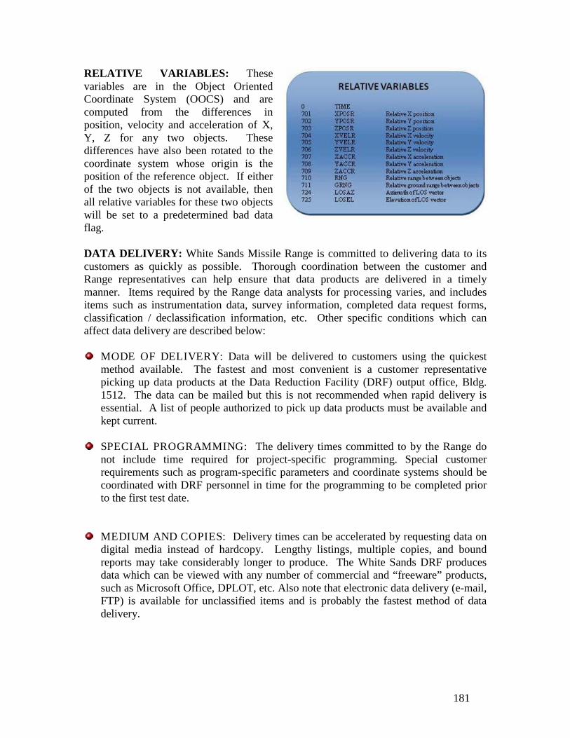
181
RELATIVE VARIABLES: These variables are in the Object Oriented Coordinate System (OOCS) and are computed from the differences in position, velocity and acceleration of X, Y, Z for any two objects. These differences have also been rotated to the coordinate system whose origin is the position of the reference object. If either of the two objects is not available, then all relative variables for these two objects will be set to a predetermined bad data flag. DATA DELIVERY: White Sands Missile Range is committed to delivering data to its customers as quickly as possible. Thorough coordination between the customer and Range representatives can help ensure that data products are delivered in a timely manner. Items required by the Range data analysts for processing varies, and includes items such as instrumentation data, survey information, completed data request forms, classification / declassification information, etc. Other specific conditions which can affect data delivery are described below:
MODE OF DELIVERY: Data will be delivered to customers using the quickest method available. The fastest and most convenient is a customer representative picking up data products at the Data Reduction Facility (DRF) output office, Bldg. 1512. The data can be mailed but this is not recommended when rapid delivery is essential. A list of people authorized to pick up data products must be available and kept current.
SPECIAL PROGRAMMING: The delivery times committed to by the Range do not include time required for project-specific programming. Special customer requirements such as program-specific parameters and coordinate systems should be coordinated with DRF personnel in time for the programming to be completed prior to the first test date.
MEDIUM AND COPIES: Delivery times can be accelerated by requesting data on digital media instead of hardcopy. Lengthy listings, multiple copies, and bound reports may take considerably longer to produce. The White Sands DRF produces data which can be viewed with any number of commercial and “freeware” products, such as Microsoft Office, DPLOT, etc. Also note that electronic data delivery (e-mail, FTP) is available for unclassified items and is probably the fastest method of data delivery.

182

183
VISUAL INFORMATION (VI) PRODUCTS APPENDIX: The terms defined below are used in the photographic industry and at WSMR to describe Visual Information products and services. These terms should be used in customer documents when requesting products or services. GRAPHIC ART PRODUCTS:
Includes consultation, design, printing, matting and laminating
PHOTOGRAPHY PRODUCTS:
High resolution still digital documentation Remote still digital photography (high resolution = 17 Megapixels) Digital still printing at Building 1621
VIDEO PRODUCTS:
Digital video/HD video for production, documentary, and remote requirements at building 1621 and building 1512
DIGITAL/ HIGH DEFINITION EDITING PRODUCTS:
Building 1621 and 2nd floor Building 1512
MEDIA REPRODUCTION PRODUCTS:
Analog and digital video duplication, CD/DVD Film to video transfers: 16mm, 35mm, and 70mm Optics high speed digital processing and duplication. Mission data composites and
Hot Wash video.
VIDEO TELECONFERENCING (VTC) PRODUCTS:
Set up and maintenance :2nd floor, south end of Building 1512 DISN VTC Center support: 1st floor, building 100
MULTI-SPECTRAL DIGITAL IMAGING PRODUCTS:
INFRARED (IR):
Dawn, Dusk, Nighttime Imaging – Completely independent of ambient light.
Adverse Weather Conditions – Provides superior contrast across long atmospheric paths, fog, dust, haze and humidity.

184
Long-Range Applications – Superior contrasts for acquisition, tracking, intercepts, and miss events.
Fragmentation Pattern & Debris Field Imaging – Ideal for nearly all HE events.
Laser-Imaging – Directed Energy programs Instrumentation and Facility Diagnostics Radiometry
VISIBLE:
Low Light Cameras high speed digital cameras Cameras synchronized to IRIG-B carrier signal. Picture Quality - high resolution 12 seconds or 4 seconds at 3000 PPS. Live Video Out – All imagers have live video out with NTSC capable. Segmented Memory – cameras have on-board segmented memory to
accommodate multiple launch and impact scenarios.
DIGITAL TRANSFER PRODUCTS: The Cintel Millennium (MMHD) is a high performance data-cine, Flying Spot (CRT) Telecine capable of transferring 16mm, 35mm standard, 35mm square (Photosonic), 35mm Vista Vision and Photosonic 10E 70mm
square format films. Video transfers are available to customers outside of WSMR. This Telecine is capable of High Definition (HD) and Standard Definition (SD) digital transfers. VI is providing SD BetaCam analog and DVCAM digital transfers over an SD interface (SDI). HD transfers are recorded over an SDI to a Panasonic, DVCPRO HD Recorder/Player (AJ-HD1200A). WSMR Visual Information is providing Final Cut Studio video editing and DVD authoring to customers using new
Macintosh workstations. The new ITK Millennium Flying Spot Telecine continues to be of interest to Ranges and organizations internal and external to DOD for its exceptional film to video transfer services.

185
NUCLEAR WEAPONS EFFECTS FACILITIES APPENDIX: RELATIVISTIC ELECTRON BEAM ACCELERATOR (REBA): The principal components of REBA are a Marx generator, a Blumlein transmission section, and an output tube. Stored low-voltage energy is converted to high-voltage energy by the Marx generator and then transferred to the Blumlein transmission line, which serves as a fast discharge, pulse-forming, low-inductance energy source for the output tube. The Marx generator basically consists of a bank of capacitors that are charged in parallel and discharged in series by means of spark-gap switches. The negative voltage output of the Marx generator is placed on the coaxial Blumlein transmission line, which consists of three concentric cylinders. The pulse formed by the Blumlein is impressed across the tube diode, made up of an insulating and vacuum-holding structure, a field-emission cathode, and an anode. The anode used for the electron-beam mode of operation is a thin, low-Z target that allows passage of the electrons with minimal energy loss. For the Bremsstrahlung mode of operation, the anode used is a thick, high-Z target, selected for maximum efficiency in converting electron beam energy into Bremsstrahlung radiation. The REBA is capable of delivering about six exposures per hour. In electron-beam mode, the total transported beam energy is approximately 6.7 kilojoules (kJ). Peak beam fluence is approximately 400 calories/square centimeter (cal/cm2). In Bremsstrahlung mode, peak dose environments of 1.8 x 10⁴ rad (Si) and peak dose rates of 2.6 x 10¹¹ rad (Si)/second are measured. Nominal pulse widths for both modes are between 50 and 70 ns. LINEAR ELECTRON ACCELERATOR (LINAC): The LINAC is a two-section, S-band accelerator powered by a pair of 21 megawatt (MW) klystrons operating at approximately 2855 megahertz (MHz). A 120 kilovolt (kV) electron beam is injected into the accelerator and the resultant accelerated beam (at levels up to 48 mega electron volts [MeV]) exits through a thin, water-cooled aluminum window. The beam diameter is approximately 1 millimeter (mm) at the exit window, with angular divergence of the beam dependent on the beam energy, which can be varied from 1-48 MeV. The electron beam may irradiate test items, or the electrons can be impacted on a thin platinum target to create high-energy Bremsstrahlung pulses with a 30-degree exit cone. Pulse reproducibility and predictability are excellent. Maximum duty ratio is 0.12%, providing a repetition rate up to 60 pulses per second (pps). Variable-delay triggers are available for instrumentation triggering, synchronized with the LINAC output pulse. LINAC parameters and operating characteristics are very flexible, and arrangements can be made for operation in other-than-routine modes, as well as for around-the-clock operation. The LINAC was specifically designed to accommodate experimenters and includes a 100 decibel (dB) screen room, a real-time digital data acquisition and processing system, support instrumentation, and extensive dosimetry. Power supplies, signal generators, multifunction meters, and other items are available upon request.

186
FAST BURST REACTOR: Pulsed output of the FBR provides maximum fluencies in free field of 6.5 x 10¹³ neutrons/square centimeter (n/cm2) with associated prompt gamma doses of 16 kilorad (silicon) krad (Si). At the normal level of 8 kilowatts (kW), steady-state power runs produce an accumulated maximum fluence with every 10 minutes of operation. A fluence increase of a factor of five may be achieved within the internal irradiation cavity of a modified core. Normal operation of the reactor is within an exposure cell 15.2 meters (m) square by 6.1 m high. Large test items may be handled through a shielded door 3.6 m wide by 4.6 m high. To accommodate special test requirements, the FBR can also be operated out of doors in an open air environment. Following operation, the reactor is remotely lowered into a shielded storage pit to allow cell access for experimenter personnel. Several materials are available for shielding test equipment from both neutron and gamma radiation. Active experiments can be monitored from the cell next to the experimenter's room using existing facility cabling installed to support instrumentation, including a real time digital acquisition and processing system. GAMMA RADIATION FACILITY (GRF): The GRF uses eight triple-encapsulated, cylindrical cobalt-60 (Co-60) sources, replaced every five years, to provide varying levels of gamma radiation. During exposure, the sources are all contained within a 0.2 m diameter circle on the front face of an exposure head assembly. System level tests can easily be conducted outside the test cell by opening the large roll-up door opposite the exposure head. Also, a segment of the roof can be removed to provide a source for overhead or airborne experiments. Any combination of the eight sources may be used to achieve the desired level of exposure. Exposure time for each of the sources is individually controllable in increments of one second. Any desired duration may be used. Real-time dose and dose-rate instrumentation is available. Users may use permanently installed cables or install their own (runs are between 30 and 70 feet). WHITE SANDS SOLAR FURNACE (WSSF): The WSSF operates in both steady-state and pulsed mode and can provide both rectangular and shaped (nuclear) pulses. A precisely machined shutter wheel is used to produce the pulse shapes characteristic of thermal pulses from nuclear detonations. The special design of the WSSF also provides the pulsed thermal environment suitable for materials testing. For a combined aerodynamic/thermal environment, the WSSF has a subsonic wind tunnel with velocities up to 183 m/s. The WSSF is a focusing, solar-energy collector with four main components: a heliostat, an attenuator, a concentrator, and a test chamber. The heliostat, an array of 356 flat mirrors on a 12.2 m wide by 11.0 m high steel structure, automatically tracks the sun to reflect thermal energy through the movable louvered blades of the attenuator to the concentrator. The concentrator consists of 180 spherical mirrors on a 9.1 m square steel frame located 29.3 m from the heliostat. Each mirror is mounted to concentrate the thermal energy at the focal plane of the facility in the test chamber. A remotely controlled, three-axis table is available for positioning of

187
experiments at the focal plane. Instrumentation includes various types of calorimeters, thermocouples, and analog and digital recording instruments. A 20-channel instrumentation van supplements the data channels that are available in the test chamber. SEMICONDUCTOR TEST LABORATORY (STL): The specific purposes of the STL include the verification of complex software survivability models, the determination and documentation of large variations in semiconductor device responses to various nuclear environments, and the tracking and documentation of changes in the manufacturing processes of various semiconductor devices used by the military. STL personnel also analyze the performance of specific system applications of devices that have been tested, generate parametric data for circuit analyses, perform lot acceptance testing for the government, and manage an ever growing database of nuclear survivability data on every device and component tested. This exhaustive database, together with the complete range of simulated nuclear environments available at SV, enables the personnel at the STL to perform any level of nuclear effects test and/or analysis required in an expedient, cost-effective manner. They can conduct basic test and data collection or a more sophisticated evaluation of a system's requirements versus the performance of the system’s piece-parts in a nuclear environment. When required, they can also perform in depth assessments of a system's nuclear survivability while in its intended use and environment.
DIRECTED ENERGY WEAPONS EFFECTS:
LASER FACILITIES:
PULSED LASER VULNERABILITY TEST SYSTEM (PLVTS): Central to the PLVTS is a closed-cycle, electric-discharge, pulsed CO2 laser. Operating at 10.6 μm, this proven laser delivers moderate to high energy levels, with low maintenance and operating costs. Power is delivered on target via the sophisticated Advanced Pointer/Tracker (APT). The total system consists of the pulsed CO2 laser, APT, control room, laser beam diagnostics, and 50 cm static output telescope, all mounted in a 60 foot System Van. A 25-foot Utility Van houses necessary ancillary equipment. For downrange target data acquisition, a 35-foot Mobile Target Van contains optics and diagnostic instrumentation. PLVTS supports a full complement of beam diagnostic instrumentation for measuring critical output parameters of the laser and selected parameters at the target plane. A Macintosh-based data acquisition system provides ease of set-up and modification of desired parameters. The PLVTS is a platform for performing survivability and hardness evaluations of weapon systems and commercially developed EO equipment.

188
.

189
CLIMATIC TEST FACILITIES APPENDIX: LARGE TEST CHAMBER: The Large Test Chamber (LTC) at Temperature Test Facility (TTF) is 105’L x 40’ W x 50’ H with the ability to conduct temperature tests ranging from –62°C to 93°C (-80°F to 200°F). In addition to these temperature extremes, solar radiation (1120 W/m2) and freezing rain/ice testing can be conducted in the LTC. SMALL TEST CHAMBER: The Small Test Chamber (STC) at TTF is 35’ L x 30’ W x 20’H with identical test capabilities as the LTC. The LTC and STC have exhaust and replenishing air capabilities to allow for the operation of equipment (gasoline engines, gasoline heaters, etc.) at the temperature extremes. SALT FOG/HUMIDITY CHAMBER: The Salt Fog/Humidity Chamber at TTF is 15’ L x 20’ W x 10’ H and is capable of conducting high temperature [ambient to 71°C (160°F)], solar radiation (1120 W/m2), humidity (95% Relative Humidity), and salt fog testing:
Temperature shock testing can be conducted by utilizing a combination of any two temperature conditioning chambers with a transition time of approximately five minutes.
The solar radiation testing (heating effects only) is conducted by the use of seven quartz lamp banks, each approximately 15' wide by 17' long, that can be suspended end to end or individually depending on the test item requirements.
ENVIRONMENTAL TEST AREA II: At ETA-II there is a large microbiological chamber for conducting fungus, high temperature, and humidity tests. This chamber has an internal dimension of 30’ L x 22’ W x 16’ H. There is a rain test bed for conducting outdoor rain testing [up to 305 mm/hr (12 in/hr)]. Two 200 hp wind generators, and a gasoline powered wind generator are available for providing winds up to 35 m/s (80 mph) over a 24’ by 10’ area. These wind generators can be utilized alone or in combination with rain or sand/dust. Two sand/dust feed systems are available for conducting unconditioned field sand/dust tests, which can supply up to 54 kg/min (120 lbs/min) of sand/dust. There also is a dust chamber with a test volume of 4' H x 4' W x 4' D. The dust chamber air temperature and relative humidity are controllable between 16°C to 71°C (60°F to 160°F) and 5% to 30% Relative Humidity. The dust chamber can supply dust concentrations up to10.6 g/m3 (0.3 g/ft3) with wind velocities of up to 29 m/s (65 mph). In addition to these test capabilities, smaller temperature chambers are available to conduct temperature, humidity, and salt fog testing on small items. When required and if the test items are safety compatible, multiple tests can be conducted simultaneously at ETA-II. The ETA-II is approved for hazardous testing of explosive test items up to 30,000 lbs of Class 1.1.

190
HOT CHAMBER: The Building 1544 Hot Chamber located on the main post is 70’ L x 24’ W x 22’ H, and has the ability of conducting high temperature [ambient to 71°C (160°F)], solar radiation (1120 W/m2), humidity (95% Relative Humidity), and salt fog testing. This facility is for non-hazardous test items only. ALTITUDE CAPABILITIES: The small multipurpose Altitude Chamber can generate altitude environments from 500 feet below sea level to 180,000 feet above sea level. Large test items are tested under natural conditions at locations at WSMR approaching 10,000 ft altitude. The locations and chamber are certified for explosive test items. FIELD CONDITIONING EQUIPMENT: Portable conditioning equipment, shrouds and power generators are available for temperature testing anywhere at WSMR or off post. The shroud size range is large enough to condition a launcher with missile (60’ L x 16’ W x 16’ H) to small enough to condition a computer chip. These field conditioning units are capable of conducting temperature tests ranging from –54°C to 71°C (-65°F to 160°F).

191
DYNAMIC TEST FACILITIES: VIBRATION TEST CAPABILITIES: The 300K Dynamic Test Facility is located 2 miles from the main post area and is approved for the testing of explosive test items up to 5,000 lbs of Class 1.1. Several electrodynamic vibration exciters are available for hazardous or nonhazardous testing. Large reaction masses accommodate multiple exciters for tests involving large forces, massive test items, or multiple degrees-of-freedom excitation. A wide range of test setups can be accommodated in particular large structure testing using multiple shakers. Simultaneous temperature conditioning testing can be accomplished during vibration and shock testing. VIBRATION CONTROL SYSTEMS: Computer-based vibration control (VC) systems include the Spectral Dynamics 2550-B (2 each) and the Data Physics Inc. Vector II Systems (2 each) which are available to provide drive signal generation and closed-loop control for stationary or transient test environments. Mixed mode vibration control capabilities are available to simulate road transport environments as follows:
WIDE BAND RANDOM:
Wide band random with multiple random narrow-bands. Wide band random with multiple (varying magnitude) narrow-bands. Wide band random with multiple sine tones. Wide band random with multiple (varying magnitude) sweeping sine
tones. Wide band random with multiple (varying magnitude) sweeping
random narrow-bands and with multiple (varying magnitude) sweeping sine tones.
Wide band random with shock pulses.
ELECTRODYNAMIC VIBRATION EXCITERS: Exciter (shaker) specifications are described in Table 1.
THREE DIMENSIONAL (3D) ELECTRODYNAMIC VIBRATION SYSTEM: The three dimensional vibration systems simultaneously produce vibration in three directions. The system is capable of testing a 100 pound item to 10 G’s peak with a frequency bandwidth of 5 to 500 Hz. The test item table size is 3 x 3 ft.
LOOSE CARGO TEST CAPABILITIES: Two loose cargo (package bounce) test machines are available. The loose cargo machines meet the requirements of MIL-

192
STD-810 and ITOP 4-2-602. The maximum test specimen weight is limited to 6,000 pounds.
SHOCK TEST CAPABILITIES: An extensive array of equipment is available for shock testing. All shock tests can be remotely controlled to accommodate explosive and hazardous test items.
SHOCK TESTING USING ELECTRODYNAMIC EXCITERS: Electrodynamic exciters can be used to produce classical pulses (half-sine, saw-tooth, trapezoidal/square-wave) and complex pulses using shock synthesis techniques. Repetitive transient and wide-band random with mixed shock pulses (transient) can also be produced.
SHOCK MACHINES: Shock tests which require classical high peak accelerations or large velocity changes can be accommodated on shock test machines. All shock test machines can be configured to provide half-sine, terminal peak sawtooth, or
trapezoidal/square-wave shock pulses. Three shock machines are available and are described in Table 2.
1 Typical shock tests range from 11 milliseconds @ 100 G’s to 35
milliseconds @ 15 G’s using long stroke gas programmer for half sine only.
2 Typical shock tests range from 6 milliseconds @ 200 G’s to 13 milliseconds @ 100 G’s using four universal gas programmers.
3 Typical shock tests include 11 milliseconds @ 35 G’s
RAIL IMPACT TESTING: Rail Impact tests are conducted in accordance with MIL-STD-810 utilizing facilities at Ft. Bliss Air Defense Center, Texas.
PENDULUM IMPACT MACHINE: A pendulum impact shock machine with a sixteen foot cable length and a 10 x 16 ft mounting platform is available for performing packaged container transportation shock tests in accordance with MIL-STD-810.

193
ROUGH HANDLING (DROP SHOCK) TESTS: Facilities are available to provide rough handling drop tests in accordance with MIL-STD-810 (Transit Drop) and ITOP 4-2-602.
PYROTECHNIC TESTING: Facilities and equipment are available to create a wide range of shock test environment specifications having extremely high acceleration levels of up to 100,000 G’s using either metal-to-metal impact fixtures or explosive based techniques to generate a test specific shock pulse (Shock Response Spectrum).
PROPULSION TEST CAPABILITIES: A horizontal thrust test stand is available for static firing rocket motors up to 40 inches in diameter and generating thrust up to 100,000 pounds-force. Motor case burst pressure tests and squib igniter tests can be accommodated. Extensive instrumentation is available for propulsion measurements including vibration, shock, pressure, strain, igniter pulse and thrust. ACCELERATION TEST CAPABILITIES: A 108-inch radius arm centrifuge is available for constant acceleration testing. The centrifuge can subject a test item weighing up to 300 pounds to a force of 100 G's. Accelerations of up to 200 G's can be achieved for small packages (< 25 pounds). Test item monitoring and support can be accomplished via the available 30 channel slip ring assembly. DATA ACQUISITION CAPABILITIES: Digital recording data acquisition systems are available. Digital data sample rates of up to 20K samples/second can be achieved for a total of 64 channels. Over 80 analog recording channels are available with a dynamic range of 40 dB over a frequency range of DC to 20 kHz. DATA PROCESSING CAPABILITIES: Data can be processed in the time, frequency, or amplitude domain. Typical data processing includes auto- and cross-correlation, power spectral density, coherence, frequency response functions, impulse response functions, probability analysis, and shock response spectrum analysis. INSTRUMENTATION CAPABILITIES: Extensive instrumentation systems are available and are capable of measuring the following: sound pressure, acceleration, velocity, displacement, force, strain, pressure, temperature, and time sequence. Mobile instrumentation vans are available to support tests performed at locations throughout the Range. LOAD TESTING AND CENTER OF GRAVITY TEST CAPABILITIES: A variety of load cells (from 5 to 100,000 lbs) and weight scales are available for performing load tests (dynamic or static) and center of gravity tests on vehicles and shelters.

194

195
CHEMISTRY LABORATORY APPENDIX: The White Sands Missile Range Chemistry Laboratory provides a wide variety of both centralized and on-site analytical services to the projects at WSMR and at other commands. These services are available to all DOD and non-DOD activities plus state and local governments. Non-government agencies can also obtain support in the same manner as government agencies. MAJOR SUPPORT CATEGORIES: The major support categories available are as follows:
Conformance Testing of Material Missile Exhaust Gas Analysis Chemical Analysis of Explosives Failure Analysis Miscellaneous Chemical Analysis Technical Consultation Environmental Quality Analysis
LABORATORY STAFF: The laboratory staff consists of seven full-time chemists. The technical breakdown is as follows:
Laboratory Director (Ph.D.) Quality Assurance Officer Lead Inorganic Chemist (M.S.) Lead Organic Chemist Inorganic Chemist Organic Chemist General Chemist
The laboratory has over 80 years of combined experience in the field of analytical and environmental chemistry and is accredited to perform targeted environmental analyses in accordance with ISO 17025 and National Environmental Laboratory Accreditation Program (NELAP). The current focus for accreditation is the analysis of hazardous waste material and other analyses as described in SW-846 and other EPA methodology. ANALYSES AVAILABLE: These analyses are inclusive but not limited to:
TCLP extraction for volatiles, semi-volatiles and metals (EPA Method 1311) Volatiles analysis (EPA Method 8260B) Semi-volatile analysis (EPA Method 8270C) Metals analysis (EPA Method 6010) Mercury analysis (EPA Method 7470A, 7471A) Ignitability (EPA Method 1010, 1020)

196
Corrosivity (EPA Method 9040B, 9045C) Petroleum hydrocarbons (EPA Method 8015 Mod., 418.1) PCBs (EPA Method 8082 modified) Explosives (EPA Method 8330) Paint filter liquid test (EPA Method 9095A)
The laboratory Quality Assurance Plan Manual can be provided upon request. Typical analytical turnaround times of 8-11 workdays can be expected for many analyses depending on holding times and complexity. Some of the more complex and/or specialized determinations may require 14-18 workdays to complete. For special requirements, shorter turnaround times can be negotiated. Sample collection is usually best handled by the customer. The Chemistry Lab will provide all required containers and preservatives for sample collection. However, there are occasions when the chemistry laboratory staff can collect samples at an additional cost. Laboratory personnel can work with you to determine your sampling needs. Analytical reports are generated within 3 days of analysis completion. Information/preliminary draft copies can be sent via fax or email at the customer’s request.

197
AIR FORCE 46TH TEST GROUP DETACHMENT 1 APPENDIX: 746TH TEST SQUADRON: The 746th Test Squadron (TS) is also known as the Central Inertial Guidance Test Facility (CIGTF). CIGTF's low dynamic mobile land navigation test labs offer an effective means for low cost performance and susceptibility test and evaluation. Each mobile lab is fully instrumented with the latest in test support equipment. Following is a description of some of the 746th Test Squadron capabilities:
GPS ELECTRONIC COMBAT (EC) TESTING: CIGTF has also developed numerous tools and processes that have established us as the leader in GPS EC threat environment testing. For example, the Portable Field Jamming System (PFJS) is one of many mobile test assets CIGTF uses for EC testing. With proper planning, GPS threat lay-downs, signal structures, and power levels can be generated to represent a realistic EC environment. Using Navigation Test and Evaluation Laboratory (NAVTEL)'s modeling and simulation development processes to create representative test scenarios allows us to effectively produce customer defined threats prior to field and flight-testing. By using NAVTEL in this process, significant savings are realized by the customer.
SLED TESTING: The 10-mile long Holloman Air Force Base High Speed Test
Track (operated by 846th Test Squadron) offers precise effective low, medium, and high dynamic operating environment for testing, evaluating, and validating GPS based guidance and control systems, inertial navigation systems, and truth reference systems. Sled Accuracy is as follows:
Distance: 0.003 ft; Velocity: 0.0013 ft/sec; Azimuth: <0.5 arcsec
FLIGHT TESTING: Following functional and performance verification in CIGTF's
laboratory and field test environments, flight testing of the item is conducted at WSMR. CIGTF's fully instrumented aircraft, including the F-16, AT-38, C-12, and UH-1 are used to provide various low, medium, and high dynamic operating environments for the system under test. Each platform is capable of hosting virtually any combination of INS, GPS, and/or integrated GPS/INS navigation and guidance systems and each platform is fully instrumented for data acquisition.
REFERENCE SYSTEMS: CIGTF provides a wide variety of TSPI Truth Reference Systems for field and flight-testing. In addition to our high dynamic sled testing, CIGTF reference systems also include CHAPS. The CIGTF High Accuracy Post-Processing System (CHAPS) provides a high accuracy validated truth reference source that can be used in either a clear or hostile EC environment.

198
TEST SUPPORT NETWORK: In support of the Congressional mandate to
integrate GPS User Equipment (UE) technology into all DOD weapon systems, CIGTF has developed a wide area differential GPS truth reference system called the “Test Support Network" (TSN). The TSN provides a superior, cost-effective, truth reference source for platform integrators to use to test and evaluate GPS based guidance and navigation systems.
LABORATORY TESTING: The Inertial Laboratory at CIGTF offers a unique,
seismically stable environment used to test precision inertial components and systems used for navigation, guidance, and control, and tracking. The Inertial Laboratory features: a Contraves 53Y three-axis table with an integrated environmental chamber mounted on an isolation pad, a Contraves 53M three-axis table mounted on an isolation pad eight, and Contraves rate and position tables.
GPS RECEIVER AND INTEGRATED SYSTEM TESTING: The CIGTF
NAVTEL is a state-of-the-art facility used for testing stand-alone GPS UE and integrated GPS navigation systems. NAVTEL enables GPS UE hardware and software to be fully exercised under laboratory conditions by using real-time simulation of GPS satellite signals in conjunction with simulated and/or hardware-in-the-loop host vehicle aiding and communication systems. The ability of NAVTEL to fully exercise and simulate realistic operational conditions, including operations in a threat environment, results in a cost effective approach to testing prior to field and flight testing.
ENVIRONMENTAL TESTING: The Environmental Laboratory at CIGTF
provides the capability to simulate actual operational profiles in low, medium, and high dynamic environments. A full spectrum of temperature, altitude, humidity, and vibration environments can be effectively created to ensure the system under test is fully exercised in a realistic hostile environment.
846TH TEST SQUADRON: HOLLOMAN HIGH SPEED TEST TRACK (HSTT): The Holloman High Speed Test Track is a rocket test and aerospace test facility which provides an efficient and safe means of testing customer test items while minimizing risks and reducing cost for a wide variety of test hardware in a near operational environment. Specific advantages are: the test items are recovered for post-run analysis; the sled provides sustained linear and dynamic acceleration and velocity with superimposed, tailored vibration; and the sled track provides extremely accurate test article positioning and time correlation. Repeated tests of the same test item provide an independent evaluation of modifications made during a development program.

199
The Holloman High Speed Test Track is the longest (50,788 feet) and most precisely aligned and instrumented facility of its kind in the world. The track is used to simulate selected trajectories of aircraft and missiles under stringent conditions. Sled speeds up to 7,000 ft/sec are routine, while speeds above 8,900 ft/sec have been demonstrated. Depending on mission needs, sled weights range from 100 to 30,000 pounds; however, heavier sleds can be operated as required. Also, depending on payload size, accelerations above 200 g's have been demonstrated. The Holloman High Speed Test Track is organized as a squadron under the 46th Test Group, a tenant organization on Holloman Air Force Base, New Mexico. It is physically located near the eastern boundary of WSMR, virtually unaffected by environmental and encroachment problems. While operated primarily for the needs of the Air Force Materiel Command, its test capabilities are also available for other Government agencies and their respective contractors. HIGH SPEED TEST TRACK (HSTT) TEST CAPABILITIES:
LETHALITY TESTING: Missiles, warheads, bombs, hit sensors, and hit-to-kill interceptors have been subjected to impact testing against stationary inert and live munition targets at speeds ranging from 3,000 to 8,000 ft/sec. To prevent sled debris contamination on a target, the sled payload or test item can be released from the sled just prior to impacting the target by means of a "pull-down" facility.
EXPLOSIVE BLAST EFFECTS TESTING: Blast effects on moving sleds are conducted with high-explosive detonations. The objective of blast testing on the track is the simulation of an explosive blast shock wave intercept on full-scale reentry vehicles and on components of aircraft, missiles, and aerospace systems during supersonic and hypersonic flight.
ENVIRONMENTAL EROSION TESTING: Rain, ice/hail, dust and other particle erosion testing have been conducted at the Test Track. Rain erosion testing is conducted to study the erosive effects of extended supersonic or hypersonic flight through rain clouds on material samples, fuzes, sensors, seeker heads, electro-optical windows, radomes, shrouds, inlet diffusers, and other components of weapons and aerospace systems. The simulation of a reentry vehicle or ICBM entering a dust or pebble environment caused by a nuclear blast have also been conducted at supersonic and hypersonic speeds. Recoverable test samples from subsonic test speeds up to 7,400 ft/sec are routine. A single test item can be mounted to existing monorail test sleds and propelled through a simulated rain field. Multiple samples on special 7-cone test fixtures or wedges attached to a monorail sled have been conducted. A standard simulated rain rate of 2.5 inches/hour through a length of 6,000 feet is also routine. Shorter lengths of simulated rain fields can be provided. Lighter rain rates have been charted and provided in accordance with special customer requirements. A 2000 foot ballistic test range adjacent to the Test Track with simulated rain rates up to 25 inches per hour has been used for artillery fuze testing.

200
HYPERSONIC ENVIRONMENTAL TESTING: Structural materials and ablative or refractory coatings are tested to evaluate aerothermal effects in a hypersonic environment. Test articles and samples included heatshields, radome covers, missile and interceptor nose cones, and shrouds. Test samples can be recovered after a sled test for post-test analysis and evaluation.
DISPENSER SYSTEMS TESTING: This category of testing encompasses the dispensing or launching of rocket-powered weapons, the dissemination of bomblets, flechettes, submunitions, and the dissemination of power-like substances from payload carriers mounted on a test sled in a dynamic environment. The dispensing of radome covers or shrouds protecting seekers or electro-optical windows have also been demonstrated at supersonic and hypersonic test speeds.
NATIONAL RADAR CROSS SECTION TEST FACILITY: The National Radar Cross Section (RCS) Test Facility (NRTF) is the premier DoD facility for RCS testing. Formerly known as RATSCAT, which began measuring radar scattering in 1963, it is comprised of two complementary sites, Mainsite and RATSCAT Advanced Measurement System (RAMS). Assigned to the U.S. Air Force’s 46th Test Group Detachment 2, NRTF is located west of Holloman Air Force Base, New Mexico in a rolling gypsum region of WSMR. NRTF specializes in the RCS characterization of full-scale, aerodynamic vehicles and antenna radiation pattern development. Due to its remote, secure environment, it can also accommodate customers requiring specialized testing of developmental electronics systems. NRTF products directly support weapon system development programs, vulnerability assessment studies, and mission planning efforts throughout the DoD.
MAINSITE: Mainsite has a ground plane RCS range with monostatic and bistatic capabilities to support a variety of targets ranging from small targets to full-scale operational targets. Both fixed and portable equipment can be set up in a wide variety of configurations for special tests. Mainsite is divided into two main ranges: The North Range, comprised of Pits 3, 5, and 6, and Pit 2 in the West Range. In addition, portable equipment can be set up in a wide variety of configurations for special tests. Test targets at Mainsite can be mounted on polystyrene foam columns of various height on rotating tables. The rotating tables accept a wide variety of targets ranging from small missiles and reentry vehicles to full-size aircraft and ground vehicles weighing up to 60,000 pounds. Measurements at Mainsite can be made at any frequency from 120 MHz to 18 GHz and at frequencies of 34 to 36 GHz and 94 GHz. Both monostatic and bistatic RCS, as well as antenna patterns, can be measured, and special measurements such as near-field, JEM, glint, and Doppler are available upon request. Additionally, a tailored data package, full test reports, including analysis and interpretation of data, and special data processing are provided to range users according to their requirements. In addition to these capabilities, Mainsite has the resources to accomplish the design and construction of model targets.
Modeling standards are based on customer requirements, radar scattering principles, and fabrication techniques. Linear model dimensions of ± 0.2 percent are routinely

201
achieved with angle accuracy of 0.05 degrees. Model Shop personnel have built models up to 58 feet in length and can perform extensive detailing to provide items such as inlet and exhaust ducts, rotating turbine and compressor blades, and moveable control surfaces. The primary support structures used at Mainsite are foam columns, constructed of beaded polystyrene. The density of the material used is dependent upon the weight of the target to be supported, with the shape designed to minimize the return signature. These columns are then attached to the appropriate sized turntable. Cranes, manlifts, forklifts and other heavy equipment are available on site for mounting of large and small targets. Typically, small, lightweight targets can be mounted to an accuracy of ±0.2 degrees in roll and pitch. Large, heavy targets can be mounted with an accuracy of ±0.5 to 1.0 degree in roll and pitch.
RADAR TARGET SCATTER (RATSCAT) ADVANCED MEASUREMENTS
(RAMS): RAMS is a self-contained, secure test complex consisting of the Target Support facility, an 8900 foot paved shadow plane range, the Central Facility, and an office complex, situated at the base of the San Andres mountains 35 miles northwest of the NRTF Mainsite.
THE TARGET SUPPORT FACILITY: boasts machine shops, a large target
preparation and storage hangar, and an underground silo. Monostatic RCS measurements of targets up to 70 feet in length can be made. Additionally, with the appropriate target rotator provided, the pylon can support target weights up to 30,000 pounds. This 95 foot target support pylon can be extended to 56 feet above the projected ground plane and retracted into a silo for visual security and for convenient target mounting and dismounting. In the secure, controlled access environment of the Target Support Facility, target mounting and preparation are facilitated by use of an overhead traveling bridge crane. A 105-foot pop-up calibration and field probe pylon is housed in an underground pit in front of the target support pylon on the extreme south end of the paved range. The Central Facility serves as the center of operations at RAMS. Within its 6000 sq. ft concrete block structure resides the radar equipment, the Command and Control Systems (CCS), computing resources, data storage vaults, personnel office space, and break rooms. All manner of classified material can be accommodated and the entire facility is equipped with 24-hour manned security presence.
586TH FLIGHT TEST SQUADRON: The 586th Flight Test Squadron (586 FLTS) performs flight tests of the most advanced aircraft systems in the world. The squadron has aircraft parking and administration facilities to provide a high level of security to its customers. It owns and operates three highly modified AT-38B aircraft equipped to support a wide variety of flight test operations. Capabilities of the squadron’s AT-38Bs include: chaff, flares, GPS navigation and precision data recording and telemetry, ECM, Air Combat Maneuvering Instrumentation (ACMI) pods, and multiple format photographic coverage (including helmet-mounted video cameras). The squadron owns and operates a highly modified C-12J (Beech 1900 Airliner) with multiple antenna and pod configurations for guidance/navigation, avionics, and electronics testing. The 586 FLTS has access to both full-scale and sub-scale unmanned aerial targets as well as one

202
of the world’s most elaborate ground impact ranges. The 586th Flight Test Squadron is the world’s leading authority on overland firings of the Air Force’s primary medium range air-to-air missile (AMRAAM).

203
CENTER FOR COUNTERMEASURES APPENDIX: The Center for Countermeasures, operating under DoD Directive 5129.47, provides independent countermeasures/ counter-countermeasures (CM/CCM) analysis, test, and evaluation of both US and foreign precision guided weapons (PGWs), and CM systems for the entire DoD community. This includes systems involving electro-optical (EO), infrared (IR), and millimeter wave (MMW) technologies. The Center, although located at WSMR, is totally mobile, conducting CM/CCM test operations on a worldwide basis. METHODOLOGY: The Center’s methodology consists of testing supported by a judicious integration of analysis and simulation. Theoretical analysis is used to determine the potential CM susceptibilities of PGWs. Analysis results are then used to design field and laboratory tests that address system susceptibilities, focusing on potential problem areas, with resulting economies in test assets and time. Simulation is used before, during and after tests to simulate actual test scenarios and establish correlation between simulation and test results. Simulation of test scenarios that are too difficult or too expensive to test usually follows this procedure. The ultimate product consists of findings, conclusions and recommendations regarding CM that improve performance of specific or generic PGW systems. FUNCTIONAL AREAS: The Center’s expertise encompasses sources, sensors, and related hardware, as well as atmospheric propagation. Functional applications include PGW guidance and control systems, target Center for Countermeasures acquisition systems, threat warning systems, expendable CM systems, infrared signature measurements, and directed energy systems. FIELD INSTRUMENTATION AND EQUIPMENT: The Mobile Instrumentation Facility (MIF) and the Operational Test and Evaluation Facility (OTEF) instrumentation vans are equipped with state-of-the-art PC-based network computers using COTS hardware and software. With these vans, data are collected and time-tagged at up to 500K samples per second. The results are real-time analog video data and near real-time digital video data. Report-quality analog/digital data in the form of high-resolution digital graphs or charts are also near real-time. The vans are deployable for use in practically all types of terrain and climatic environments. DIGITAL ENHANCED SEEKER VAN (DESV) AND IT’S KINETO TRACKING MOUNT (KTM): are used to collect missile seeker data at 800 Kbits/sec. Equipped with high-end PC-based computers, it can simultaneously collect data from eight different types of seekers mounted on the KTM. The DESV can collect up to eight channels of data per seeker and data availability is near real-time. Seekers used are both domestic and foreign. REMOTE LAUNCHER SYSTEM: The Center has three highly mobile Remote Launcher System (RLS) that are used in different types of configurations to remotely launch both domestic and RLS Missile Launcher foreign shoulder fired missiles. Each

204
RLS is equipped with time annotated video recording capabilities to capture events of the missile flight. JOINT MOBILE INFRARED COUNTERMEASURE TESTING SYSTEM (JMITS): is a self-contained mobile unit designed to test aircraft countermeasures to MANPADS threats. The system consists of a tracking mount outfitted with missile simulator capable of transmitting threat representative UV and IR missile signatures. In addition the JMITS is accoutered with IR and UV radiometers, a static threat seeker suite, and an atmospheric measurement suite for characterizing atmospheric conditions. The Center has two JMITS units. PYROTECHNICS: The Center’s inventory includes various pyrotechnics such as smoke pots, smoke grenades, aircraft flares, training munitions, and unique heat sources. The Center also has access to the entire military inventory of pyrotechnics as required. FOG, SMOKE, AND FOAM GENERATORS: Unique camouflage nets with visible, infrared, millimeter wave and suppressive characteristics are also available for the Center’s CM field tests. Two of the Center’s aircraft targets have been provided to WSMR Aerial Cable Range (ACR) for use in ACR tests. MILLIMETER WAVE ECM THREAT SIMULATOR (METS): can employ 18 different Electronic Countermeasure (ECM) techniques using selectable millimeter wave frequency bands. This ECM capability includes nonresponsive, transponder, and repeater jamming techniques. The system has a detachable remotely controlled test bed and the controls and data collection functions are housed in an environmentally-controlled mobile van. SOURCES: The Center uses many lasers and non-coherent sources in CM field tests. These lasers and noncoherent sources cover the spectrum from ultraviolet to far infrared. These lasers provide false target generation against laser guided PGW systems and non-destructive CM effects against threat warning systems and targeting systems. Most of the non-coherent sources are unique. LASER LABORATORY FACILITIES: The Center maintains and operates approximately 100 lasers from the deep ultraviolet through the far-infrared spectrum. A variety of non-coherent sources of various wavelengths are in inventory. Calibration, diagnostic and repair equipment and instrumentation used to support laboratory and field testing are also maintained and operated. THE MILLIMETER WAVE LABORATORY (MMWL): capabilities include collection of data on reflectivity, scattering, absorption, and penetration by MMW emissions. Active jamming and other types of countermeasure procedures are also used during laboratory and field testing. RADIOMETRIC SUPPORT: The Center has developed a "world-class" radiometric instrumentation suite dedicated to signature characterization of a host of military assets

205
and threats. The sensor suite consists of a variety of 3 – 5 micron Fourier transform spectrometers (FTS) and an 8 - 12 micron FTS. The premier spectrometer is a custom-made ultra-violet/visible/infrared FTS. Spectroscopic analysis of gaseous emissions from combustion by-products includes investigations at the atomic and molecular level. The imager suite consists of several 3 - 5 micron imagers, an 8 - 12 micron imager, a dedicated 8 - 12 micron imager used for contrast tracking, a wide field-of view (FOV) visible scene imager and an extreme narrow FOV tri-focal imaging system. Meteorological data, including ozone concentrations, are recorded in-situ and can be input in near real-time to an advanced atmospheric transmittance/radiance model. INFORMATION SYSTEM (IS): The CCN IS supports a modern client/server computer system providing digital/multimedia graphics analysis and end product production services. CLIENT/SERVER COMPUTER SERVICES: Separate analyst workstations, as well as in the field laptop computer resources, support all CM testing and analysis efforts. The client/server system consists of 12 servers with a RAID 5 storage capacity of more than 87 gigabytes and server-to-workstation connectivity using a 100-Mb/sec switched packet Ethernet backbone. This system provides extremely fast turn around of the customer's final products. PRODUCTION SERVICES: The Center provides the customer with fast turn around multimedia centered test result and analysis products. We have a state-of-the-art graphics production capability supported by color document reproduction and poster size color production (3 ft wide by 300 ft long). The Center is continually working towards a paperless environment as its reports are now presented to the customer in CD ROM format. The agency can also mass produce CD ROMs. Customer tests are also supported by analog and digital photographs and video that is incorporated into the customer's final product.

206

207
FAMILY & MORALE, WELFARE AND RECREATION (MWR) APPENDIX:

208

209
References
ADSS VDL Training Manual Command Briefing 2010 Document 501-08: Universal Documentation System, January 2008; Prepared by Range
Operations Group Range Commanders Council; Published by Secretariat Range Commanders Council, White Sands Missile Range, New Mexico, 88002-5110
DTC PAM 73-1 and Appendix April 2006 FDO SOP January 2008 Holloman Air Force Base High Speed Test Track Facilities and Capabilities Book, September
2006 Memorandum, Access Control Procedures May 2007 Memorandum of Instruction – Non DoD Customer Accounts Charge Rates October 2007 NEPA Process Guide March 2002 Newcomer’s Brief May 2006 Optics Capabilities Document Process Guidance for Customer Test Service Inquiries - and - Test Service Proposal Transition to
Execution, September 2006, White Sands Missile Range, Material Test (MT) Directorate, Business Development Office (BDO)
WSMR 10 Series 2010 WSMR HAZCOM Program Document February 2008 WSMR Public Affairs Office, Visual Information, and Range Optics images WSMR Reg 73-1 Customer Proposals WST 385-1Policy for Training Conducted on White Sands Missile Range (WSMR) www.nasa.gov; www-pao.ksc.nasa.gov/kscpao/nasafact/pdf/TALsites-06.pdf

210

211
Notes
SPECIAL THANKS: Special thanks to the Executive Development Class of 2007 for their initial research of materials for the original WSMR Customer Handbook.
SPECIAL NOTE: The citation of trade names and names of manufacturers in this document is not to be interpreted as official Government endorsement or approval of commercial products or services. The policies, procedures and guidelines described in this handbook are subject to change without notice.
CUSTOMER COMMENTS: Send comments on this handbook to: Business Development Office US Army White Sands Missile Range ATTN: TEDT-WS-CSPB (Margaret Tyree) White Sands Missile Range, New Mexico 88002 [email protected] Phone: (866) 532-9767 Fax: (575) 678-5010

212
213
Acronyms
3-D Three Dimensional 4DWX Four Dimensional Weather Modeling 4-H Head, Heart, Hands, Health 586 FLTS 586th Flight Test Squadron 746TS 746th Test Squadron AAFES Army and Air Force Exchange Service AAR After Action Report ABL Airborne Laser ABRES Advanced Ballistic Reentry System ACMI Air Combat Maneuvering Instrumentation ACOE Army Communities of Excellence ACR Aerial Cable Range ADIU Advanced Digital Interface Unit ADSS ATEC Decision Support System AETF Army Evaluation Task Force AF Air Force AF Air Force AFATDS Army Field Artillery Tactical Data System AFC Area Frequency Coordinator AFR Air Force Regulation AFRL Air Force Research Laboratory AGL Above Ground Level AH-1 Cobra Attack Helicopter AH-64 Apache Attack Helicopter AIM Abrams Integrated Management M1A1 Tank AIM Air Intercept Missile ALTS Aided Laser Tracking System A-MANPADS Advanced Man-Portable Air Defense Systems AMRAAM Advanced Medium Range Air-to-Air Missile AN/ARQ Airborne Radio Multipurpose Special Equipment GPS Instrumentation Pod AN/FPS Army Navy Fixed Pulsed System AN/MPS Army Navy Mobile Pulsed System AR Army Regulations ARAV Aegis Readiness Assessment Vehicle arcsec Arc Second ARDS Advanced Range Data System ARL Army Research Laboratory ARTCC Albuquerque Air Route Traffic Center ASP Ammunition Storage Point, Ammunition Supply Point ASROC Antisubmarine Rocket ASTM American Society for Testing Materials ASWR Attack, Sense, Warning, and Response AT-38 Talon Advanced Trainer Aircraft AT-38B Holloman Talon Aggressor Trainer Aircraft ATACMS Army Tactical Missile System ATC Air Traffic Control ATEC Army Test and Evaluation Command ATIN ATEC Test Integration Network ATO Approval to Operate

214
AV-8B Harrier Marine Corps Aircraft AVI Audio Video Interleave B-52 Strato-Fortress Bomber Aircraft BAT PAS Brilliant Anti-Tank Precision Acquisition System BCT Brigade Combat Team BD Business Development BDO Business Development Office BE Battlefield Environment BEAR Basic Expeditionary Airfield Resources BLOS Beyond Line-of-Sight BQM-34 Firebee Target Drone Aircraft BRTV Battlespace Real-time Video BTA Beam Transfer Area C & L Capabilities and Limitations C(A) Coarse Acquisition C-12 Huron Transport Aircraft C-12J Beech 1900 Airliner Transport Aircraft C-17 Globemaster III Transport Aircraft C2V Command and Control Vehicle C4ISR Command & Control, Communications, Computers, Intelligence, Surveillance and Reconnaissance C-5A Galaxy Transport Aircraft CAAM Computer Aided Artillery Met CaF2:Mn Calcium Fluoride Manganese Cal ID Calibration Identification cal/cm2 Calories Per Square Centimeter C-Band Frequency from 8 to 4 GHz or 3.75 to 7.5 cm wavelength CBRNE Chemical, Biological, Radiation, Nuclear and Explosive CCM Center for Countermeasures CCS Command and Control Systems CCTV Closed Circuit Television CD Compact Disk CD ROM CD Read Only Memory CHAPS CIGTF High Accuracy Post-Processing System CHS-2 Common Hardware Software 2 ChuSam CHU Surface to Air Missile CIGTF Central Inertial Guidance Test Facility CISD (BED) Computational & Information Sciences Directorate (Battlefield Environment Division) CJCSI Chairmen, Joint Chiefs of Staff Instruction Class A1 Official government organizations Class A2 Official government organization contractors CM/CCM Countermeasures/ Counter Countermeasures CO2 Carbon Dioxide COE Center of Expertise CONOPS Concept of Operations CONUS Continental United States COP Common Operating Picture COTS Cost Off the Shelf CRCC Cox Range Control Center CW Continuous Wave DA Department of the Army DAA Designated Approval Authority dB Decibel DCP Data Collection Point DE Directed Energy DESV Digital Enhanced Seeker Van Det 1 46th TG Air Force 46th Test Group Detachment 1 DFCS Drone Formation Control System DGT Digital Frequency Translator DHS Department of Homeland Security DISN/DDN Defense Information Systems Network/ Defense Date Network DISR DoD Information Technology Standards Registry DITSCAP DoD Information Assurance Certificate and Accreditation Process (DIACAP supersedes)

215
DLGS Data Link Ground System DLT Data Link Transceiver DOAMS Distant Object Attitude Measurement System DoD Department of Defense DoDD Department of Defense Directive DoDI DoD Instruction DOF Degrees of Freedom DOPA Description of Proposed Action DREN Defense Research and Engineering Network DRF Data Reduction Facility DS Data Sciences Directorate DSL Digital Subscriber Line DSN Defense Switched Network, Digital Switched Network DT Distributed Testing DTC Developmental Test Command DTCC Distributed Test Control Center DTCS Drone Target Control System DTRA Defense Threat Reduction Agency DVD Digital Versatile Disk (formerly Digital Video Disk) E3 Electromagnetic environmental effects (E3) ECM Electronic Counter Measures EDP Excessive Deficit Procedure EDX Energy Dispersive X-ray EIS Environmental Impact Statement EMC Electro Magnetic Charge EMCON Electromagnetic Emission Control EMFAV Electromagnetic Vulnerability Assessment Facility EMI Electro Magnetic Interference EMP Electro Magnetic Pulse EMR Electromagnetic Radiation EMRH Electromagnetic Hazard EMRO Electromagnetic Operational EO Electro-Optical EO/IR Electro-Optical/ Infrared EOCM Electro-Optical Countermeasures EOCMFS Electro-Optical Countermeasures Missile Flight Simulator EOD Explosive Ordnance Disposal EOVAF Electro-Optical Vulnerability Assessment Facility EPA Environmental Protection Agency ERGM Extended Range Gun Munitions ERMP Extended Range Multi-Purpose ESD Electrostatic Discharge ETA Effects Test Area ETA-II Environmental Test Area II EW Electronic Warfare EXSUM Executive Summaries F-14 Tomcat Fighter Aircraft F-15 Eagle Fighter Aircraft F-16 Fighting Falcon Fighter Aircraft F-18 Hornet Fighter Aircraft F-4 Phantom Fighter Aircraft FAA Federal Aviation Agency FAD Force Activity Designator FBR Fast Burst Reactor FDO Foreign Disclosure Office FFT Fast Fourier Transform FLM Focused Lethality Munition FM Frequency Modulation FM Field Manual FMECA Failure Modes, Effects, and Critical Analysis FMMS Field Mobile Measurement System FMS Foreign Military Sales FMS Flight Management System

216
FOUO For Official Use Only FOV Field of View FSO Flight Safety Officer FSTE Fiber Site Terminating Equipment Ft Feet Ft/sec Feet per Second FTP File Transfer Protocol FTS Flight Termination System FTS Fourier Transform Spectrometers FW Figher Wing G & A General and Administrative GALIX French counter measure system using smoke or aerosol grenade GBAD Ground Based Auto Destruct Gbps Gigabyte per Second GCS Ground Control Station GEM Graphite-Epoxy GHz GigaHertz GIG Global Information Grid GIG-ES GIG - Enterprise Services GIS Geographic Information Systems GMLRS Guided MLRS GMT Greenwich Mean Time GPS Global Positioning System GR1 Tornado Royal Air Force (RAF) Aircraft GRF Gamma Radiation Facility GS Government Series Gs Gigaseconds GTP Ground Based Translator Processing System GWOT Global War On Terrorism HAFB Holloman Air Force Base HAIPE High Assurance Internet Protocol Encryptor HAZCOM Hazardous Communication HD High Definition HELSTF High Energy Laser Systems Test Facility HERF Hazards of Electromagnetic Radiation to Fuel HERO Hazards of Electromagnetic Radiation to Ordnance HERP Hazards of Electromagnetic Radiation to Personnel HF/DF Hydrogen Fluoride/ Deuterium Fluoride HFE Human Factors Engineering HM Hazardous Material HMARS High Mobility Artillery Rocket System HMMWV High Mobility Multipurpose Wheeled Vehicle HPM High Powered Microwave HQDA Headquarters, Department of Army HSDV High Speed Digital Video HSTT Holloman High Speed Test Track HTA Hazardous Test Area HVC Human Use Committee HWIL Hardware in the Loop I & Q In-Phase and Quadrature IA Information Assurance IATO Interim Approval to Operate IAW In Accordance With ICBM Intercontinental Ballistic Missile ICV Infantry Combat Vehicle IF Intermediate Frequency IH Industrial Hygiene IIP Instantaneous Impact Predictor ILS Integrated Logistics Support IMBC Improved Mortar Ballistic Computer IMETS Integrated Meteorological System IMU Inertial Measurement Unit

217
INS Inertial Navigation System IO Lab Information Operations Laboratory IP Internet Protocol IR Infra-Red IRCC Integrated Range Control Center IRCC Inter-Range Control Center IRIG Inter Range Instrumentation Group IRSP Instrumentation Radar Support Program IS Information System IT Information Technology ITAM Integrated Training (and Testing) Area Management Program ITO Invitational Travel Orders ITOP International Test Operations ITR Information, Ticketing, and Registration IV & V Independent Verification and Validation IWEDA Integrated Weather Effects Decision Aid JASSM Joint Air-to-Surface Standoff Missile JCIET02 Joint Combat Identification Evaluation Team Single Integrated Air Picture (SIAP) Event 2002 JDAM Joint Direct Attack Munitions JDETS Joint Directed Energy Test Site JFK John Fitzgerald Kennedy JITC Joint Interoperability Test Command JMITS Joint Mobile Infrared Countermeasure Testing System JTAGS Joint Tactical Ground Station kFt Kilo Feet KG Encryption KIP Key Interface Profile kJ Kilo Joule Km Kilometer km Kilo Meter KPP Key Performance Parameter kRad Kilo Rad KTM Kineto Tracking Mount kV Kilo Volt LAN Local Area Network LATS Launch Area Theodolite Systems LC Launch Complex LC-34 Launch Complex 34 LC-35E Launch Complex 35 East LC-35N Launch Complex 35 North LC-35W Launch Complex 35 West LC-36 Launch Complex 36 LDD Laser Demonstration Device LINAC Linear Electron Accelerator LMA Lightning Map Array LNO Liaison Officer LOA Letters of Agreement LOS Line of Sight LTC Large Test Chamber LTC Lieutenant Colonel LTF Lightning Test Facility LVC Large Vacuum Chamber LVC Live, Virtual and Constructive m Meter M & S Modeling and Simulation M4 Model 4 MAF Missile Assembly Facility MANPADS Man-Portable Air Defense System MANPRINT Manpower and Personnel Integration MATS Multimode Automatic Tracking Systems Mb Mega Bytes

218
Mb/s Mega Bytes per Second MCO Marine Corps Orders MCS Mounted Combat System Met Meteorology METL Mission-Essential Task List MeV Mega Electron Volt MGV Manned Ground Vehicle MHz Mega Hertz MIJI Meaconing, Intrusion, Jamming, or Interference MIL-STD Military Standards MIRACL Mid-Infrared Advanced Chemical Laser MIRT Mobile Infrared Telescope MK Mark MLK Martin Luther King MLRS Multiple Launch Rocket System MMS Mobile Profiler Proof of Concept Measurement System MOA Military Operating Areas MOTR Multiple Object Tracking Radars MP Microsoft Project MPARS Mission Playback Analysis and Reporting System Mph Miles per Hour MQM-107 Beechcraft Streaker Target Drone Aircraft MRGS Master/Remote Ground Station MRTFB Major Range and Test Facility Base MSDS Material Safety Data Sheet MSL Mean Sea Level MSP Minimum Support Plan MT Materiel Test Directorate MTS Mobile Telemetry System MTV Mobile Telemetry Van MTV Mobile Television Van MULE Multifunction Utility/Logistics and Equipment Vehicle MV-E Medical Vehicle – Evacuation MV-T Medical Vehicle – Treatment MW Mega Watt MWR Morale, Welfare and Recreation n/cm2 Neutrons per Square Centimeter NASA National Aeronautics and Space Administration NATO North Atlantic Treaty Organization NAVTEL Navigation Test and Evaluation Laboratory NCOW RM Net-Centric Operations and Warfare Reference Model NDL Nuclear Dosimetry Laboratory NELAP National Environmental Laboratory Accreditation Program NEPA National Environmental Policy Act NetOps Network Operations NGA National Geospatial Intelligence Agency NIST National Institute of Standards and Technology NLOS Non-Line-of-Sight NLOS-C Non-Line-of-Sight Cannon NLOS-LS Non-Line-of-Sight Launch System NLOS-M Non-Line-of-Sight Mortar NLT Not Later Than NM New Mexico NM2 Nautical Miles Squared NMD-GBR-P National Missile Defense - Ground Based Radar – Prototype NR-KPP NetReady – KPP NRO National Reconnaissance Office NRTF National Radar Cross Section Test Facility NRZ-L Non-Return to Zero Level ns Nano Second NSSM NATO Seasparrow Missile NTDIS Non-Track Digital Instrumentation System NTIA National Telecommunications and Information Administration NW Northwest

219
OIC Operational Incident Commander OLTC Open-Loop Tracking Complex OMF Optical Maintenance Facility OOCS Object Oriented Coordinate System OOTW Operations Other Than War OPNAVINST Operational Navy Instruction OR Operational Requirements ORCA Optics Remote Control and Acquisition OTEF Operational Test and Evaluation Facility P(Y) Precision Code Encrypted PAC-3 PATRIOT Advanced Capability 3 Missile PAM Precision Attack Missile PAM Pamphlet PATRIOT Phased Array Tracking to Intercept of Target PBX Private Branch Exchange PC Personal Computer PCM Pulse-Code Modulation PEO STRI Program Executive Office Simulation, Training, and Instrumentation PFJS Portable Field Jamming System PFS Project Facility Station PGW Precision Guided Weapon PHDNSWC - WS Port Hueneme Division Naval Surface Warfare Center Detachment White Sands PI Program Introduction ROM Rough Order of Magnitude PLVTS Pulsed Laser Vulnerability Test System PM-NV/RSTA Project Manager – Night Vision/ Reconnaissance, Surveillance, and Target Acquisition PNG Portable Network Graphics POC Point-of-Contact PPS Packets per Second PPS Pulses per Second PRAT Project Review and Assignment Team PT Physical Training PX Post Exchange QASAS Quality Assurance Specialist Ammunition Surveillance QF-100 Super Saber Target Drone QF-106 Delta Dart Target Drone QF-4 Phantom Air Force Drone Aircraft QoS Quality of Service R & D Research and Development Rad Radiation Absorbed Dose RADS Radar Acquisition Display System RAID Redundant Array of Inexpensive Disks RAJPO Range Applications Joint Program Office RAM Reliability, Availability and Maintainability RAM Rolling Airframe Missile RAMS RATSCAT Advanced Measurement System RATSCAT Radar Target Scatter RCC Range Commanders Council RCCF PAS Range Control Center Facility Precision Acquisition System RCS Radar Cross Section RDAS Remote Data Acquisition System RDT&E Research, Development, Test and Evaluation RDTPS Real time Data Processing System REBA Relativistic Electron Beam Accelerator REG Regulation REM Range Encryption Module RF Radio Frequency RFA Radio Frequency Authorization RFCM Radio Frequency Countermeasure RFP Request for Proposal RFTS Requests for Test Services RICS Remote Instrument Control System
220
RLS Remote Launcher System RO Range Engineer RO Range Operations Directorate ROC Record of Environmental Consideration RRV Relay and Recording Van RSO Range Safety Officer RSV Reconnaissance and Surveillance Vehicle RTCA Real-time Casualty Assessment RTDPS Real-time Data Processing System RTFDDA Real-time Four-Dimensional Data Assimilation RTO Responsible Test Organization RWP Radar Wind Profiler SAMS Surface Automated Measurement System SAR Safety Assessment Report S-band Frequency from 4 to 2 GHz or 7.5 to 15 cm wavelength SCI Sensitive Compartmented Information SD Standard Definition SDB Small Diameter Bomb SDI Standard Definition Interface SE Systems Engineering Directorate SE SouthEast SEM Scanning Electron Microscopy SFAF Standard Frequency Action Format Si Silicon SIPRNET Secret Internet Protocol Router Network SLA Service Level Agreement SLAD Survivability/Lethality Analysis Directorate SLBD Sea Lite Beam Director SLV Survivability, Lethality and Vulnerability SM STANDARD Missile SM/SSM Smart Munitions/Smart Submunitions SMART-IP Smart Impact Prediction System SMD Surface Miss Distance SOC or SC Statement of Capability SOMTE Soldier, Operator, Maintainer, Test and Evaluation SOP Standard Operating Procedure SOQPSK Shaped Offset Quadrature Phase-Shift Keying SOSI System-of-systems integration SPAN Security Policy Automation Network Squirt Site LC-37 Advanced Gun Munitions Test Site SSCS Selected Stationary Coordinate System SSOP Safety SOP STC Small Test Chamber STDC SANDS Technical Data Center STEP Software Test and Evaluation Panel STEWS-NR-P White Sands - National Range – Projects STL Semiconductor Test Laboratory STS Space Transportation System STTF Solar Thermal Test Facility SUGV Small Unmanned Ground Vehicle SV Survivability, Vulnerability & Assessment Directorate SVDLS Secure VDLS T & E Test and Evaluation T-38 Talon Trainer Aircraft TACAN Tactical Air Navigation TAIS Tactical Airspace Integration System TARS Telemetry Acquisition and Relay System TB Med Medical Technical Bulletin TC Training Circular TCLP Toxicity Characteristic Leaching Procedure TCP Transmission Control Protocol TDC Telemetry Data Center TDM Time-Division Multiplexed TECC Test Environment Certification Complex

221
TEDT-WS-CSP-B White Sands Missile Range, Plans and Operations, Business Development Office TEDT-WST-DSSTR White Sands Range Frequency Management Office TEMP T & E Master Plan TGRS Translated GPS Ranging System TGTD Test Group Test Directorate THAADS Terminal High Altitude Area Defense System TIR Test Incident Report TLD Themo-Luminescent Dosimeter TM Telemetry TMA Time of Minimum Approach TMR Target Motion Resolution TO Test Officer TOP Test Operation Procedure TRA Training Readiness Authority TRAC Training and Doctrine Command Requirements Analysis Center TRACS Transportable Range Augmentation and Control System TRADOC Training and Doctrine Command TREE Transient Radiation Effects on Electronics TSARC Test Schedule and Review Committee TSN Test Support Network TSN-IP Test Support Network - Internet Protocol TSPI Time Space Position Information TTARS Transportable Telemetry Acquisition and Relay System TTAS Telemetry Acquisition Systems TTF Temperature Test Facility TTS Transportable Telemetry System UAS Unmanned Aerial Systems UAV Unmanned Aerial Vehicles UDP User Datagram Protocol UDS Universal Documentation System UE User Equipment UGS Unmanned Ground Systems UGV Unmanned Ground Vehicles UH-1 Huey Multipurpose Helicopter UHF Ultra High Frequency UPS Universal Power Supply US United States USAG US Army Garrison USAG-DPTMS USAG - Directorate Plans, Training, Mobility, Security USMC United States Marine Corp USPO United States Post Office UTS Universal Time Standard UV Ultra Violet UXO Unexploded Ordnance V-2 Vengeance (Vergeltungswaffe) Rocket V-angle Vertical Angle VC Vibration Control VDC Volts Direct Current VDL VISION Digital Library VDLS VISION Digital Library System VHF Very High Frequency VHS Video Home System VI Visual Information VICS Video Instrument Control System VIP Very Important Person VISION Video Indexing For Searching Over Networks VISOR Virtually Integrated System for Optical Replay VLA Vertical Launch ASROC VPN Virtual Private Network VTC Video Teleconference WC-50 West Center 50 WD Work Days

222
WF Wind Finder WGS World Geodetic System WITs Warhead Impact Target WSDM White Sands Data Management WSMR White Sands Missile Range WSMRR WSMR Regulation WSNM White Sands National Monument WSSH White Sands Space Harbor WSTC White Sands Test Center WSTF White Sands Test Facility X-Band Frequency from 7 to 12.5 GHz or 2.5 to 4 cm wavelength μs Micro Second

223
Reverse Acronyms
586th Flight Test Squadron 586 FLTS 746th Test Squadron 746TS Above Ground Level AGL Abrams Integrated Management M1A1 Tank AIM Advanced Ballistic Reentry System ABRES Advanced Digital Interface Unit ADIU Advanced Man-Portable Air Defense Systems A-MANPADS Advanced Medium Range Air-to-Air Missile AMRAAM Advanced Range Data System ARDS Aegis Readiness Assessment Vehicle ARAV Aerial Cable Range ACR After Action Report AAR Aided Laser Tracking System ALTS Air Combat Maneuvering Instrumentation ACMI Air Force AF Air Force 46th Test Group Detachment 1 Det 1 46th TG Air Force Regulation AFR Air Force Research Laboratory AFRL Air Intercept Missile AIM Air Traffic Control ATC Airborne Laser ABL Airborne Radio Multipurpose Special Equipment GPS Instrumentation Pod AN/ARQ Albuquerque Air Route Traffic Center ARTCC American Society for Testing Materials ASTM Ammunition Storage Point, Ammunition Supply Point ASP Antisubmarine Rocket ASROC Apache Attack Helicopter AH-64 Approval to Operate ATO Arc Second arcsec Area Frequency Coordinator AFC Army and Air Force Exchange Service AAFES Army Communities of Excellence ACOE Army Evaluation Task Force AETF Army Field Artillery Tactical Data System AFATDS Army Navy Fixed Pulsed System AN/FPS Army Navy Mobile Pulsed System AN/MPS Army Regulations AR Army Research Laboratory ARL Army Tactical Missile System ATACMS Army Test and Evaluation Command ATEC Assistant Secretary Of The Army For Acquisition, Logistics And Technology ASAALT ATEC Decision Support System ADSS ATEC Test Integration Network ATIN Attack, Sense, Warning, and Response ASWR

224
Audio Video Interleave AVI Basic Expeditionary Airfield Resources BEAR Battlefield Environment BE Battlespace Real-time Video BRTV Beam Transfer Area BTA Beech 1900 Airliner Transport Aircraft C-12J Beechcraft Streaker Target Drone Aircraft MQM-107 Beyond Line-of-Sight BLOS Brigade Combat Team BCT Brilliant Anti-Tank Precision Acquisition System BAT PAS Business Development BD Business Development Office BDO Calcium Fluoride Manganese CaF2:Mn Calibration Identification Cal ID Calories per Square Centimeter cal/cm2
Capabilities and Limitations C & L Carbon Dioxide CO2 CD Read Only Memory CD ROM Center for Countermeasures CCM Center of Expertise COE Central Inertial Guidance Test Facility CIGTF Chairmen, Joint Chiefs of Staff Instruction CJCSI Chemical, Biological, Radiation, Nuclear and Explosive CBRNE CHU Surface to Air Missile ChuSam CIGTF High Accuracy Post-Processing System CHAPS Closed Circuit Television CCTV Coarse Acquisition C(A) Cobra Attack Helicopter AH-1 Command & Control, Communications, Computers, Intelligence, Surveillance & Reconnaissance C4ISR Command and Control Systems CCS Command and Control Vehicle C2V Common Hardware Software 2 CHS-2 Common Operating Picture COP Compact Disk CD Computational & Information Sciences Directorate (Battlefield Environment Division) CISD (BED) Computer Aided Artillery Met CAAM Concept of Operations CONOPS Continental United States CONUS Continuous Wave CW Cost Off the Shelf COTS Countermeasures/ Counter Countermeasures CM/CCM Cox Range Control Center CRCC Data Collection Point DCP Data Link Ground System DLGS Data Link Transceiver DLT Data Reduction Facility DRF Data Sciences Directorate DS Decibel dB Defense Information Systems Network/ Defense Date Network DISN/DDN Defense Research and Engineering Network DREN Defense Switched Network, Digital Switched Network DSN Defense Threat Reduction Agency DTRA Degrees of Freedom DOF Delta Dart Target Drone QF-106 Department of Defense DoD Department of Defense Directive DoDD

225
Department of Homeland Security DHS Department of the Army DA Description of Proposed Action DOPA Designated Approval Authority DAA Developmental Test Command DTC Digital Enhanced Seeker Van DESV Digital Frequency Translator DGT Digital Subscriber Line DSL Digital Versatile Disk (formerly Digital Video Disk) DVD Directed Energy DE Distant Object Attitude Measurement System DOAMS Distributed Test Control Center DTCC Distributed Testing DT DoD Information Assurance Certificate and Accreditation Process (DIACAP supersedes) DITSCAP DoD Information Technology Standards Registry DISR DoD Instruction DoDI Drone Formation Control System DFCS Drone Target Control System DTCS Eagle Fighter Aircraft F-15 Effects Test Area ETA Electro Magnetic Charge EMC Electro Magnetic Interference EMI Electro Magnetic Pulse EMP Electromagnetic Emission Control EMCON Electromagnetic Environmental Effects (E3) E3 Electromagnetic Hazard EMRH Electromagnetic Operational EMRO Electromagnetic Radiation EMR Electromagnetic Vulnerability Assessment Facility EMFAV Electronic Counter Measures ECM Electronic Warfare EW Electro-Optical EO Electro-Optical Countermeasures EOCM Electro-Optical Countermeasures Missile Flight Simulator EOCMFS Electro-Optical Vulnerability Assessment Facility EOVAF Electro-Optical/ Infrared EO/IR Electrostatic Discharge ESD Encryption KG Energy Dispersive X-ray EDX Environmental Impact Statement EIS Environmental Protection Agency EPA Environmental Test Area II ETA-II Excessive Deficit Procedure EDP Executive Summaries EXSUM Explosive Ordnance Disposal EOD Extended Range Gun Munitions ERGM Extended Range Multi-Purpose ERMP Failure Modes, Effects, and Critical Analysis FMECA Fast Burst Reactor FBR Fast Fourier Transform FFT Federal Aviation Agency FAA Feet Ft Feet per Second Ft/sec Fiber Site Terminating Equipment FSTE Field Manual FM Field Mobile Measurement System FMMS Field of View FOV

226
Fighter Wing FW Fighting Falcon Fighter Aircraft F-16 File Transfer Protocol FTP Firebee Target Drone Aircraft BQM-34 Flight Management System FMS Flight Safety Officer FSO Flight Termination System FTS Focused Lethality Munition FLM For Official Use Only FOUO Force Activity Designator FAD Foreign Disclosure Office FDO Foreign Military Sales FMS Four Dimensional Weather Modeling 4DWX Fourier Transform Spectrometers FTS French counter measure system using smoke or aerosol grenade GALIX Frequency from 4 to 2 GHz or 7.5 to 15 cm wavelength S-band Frequency from 7 to 12.5 GHz or 2.5 to 4 cm wavelength X-Band Frequency from 8 to 4 GHz or 3.75 to 7.5 cm wavelength C-Band Frequency Modulation FM Galaxy Transport Aircraft C-5A Gamma Radiation Facility GRF General and Administrative G & A Geographic Information Systems GIS GIG - Enterprise Services GIG-ES Gigabyte per Second Gbps Giga Hertz GHz Giga Seconds Gs Global Information Grid GIG Global Positioning System GPS Global War on Terrorism GWOT Globemaster III Transport Aircraft C-17 Government Series GS Graphite-Epoxy GEM Greenwich Mean Time GMT Ground Based Auto Destruct GBAD Ground Based Translator Processing System GTP Ground Control Station GCS Guided MLRS GMLRS Hardware in the Loop HWIL Harrier Marine Corps Aircraft AV-8B Hazardous Communication HAZCOM Hazardous Material HM Hazardous Test Area HTA Hazards of Electromagnetic Radiation to Fuel HERF Hazards of Electromagnetic Radiation to Ordnance HERO Hazards of Electromagnetic Radiation to Personnel HERP Head, Heart, Hands, Health 4-H Headquarters, Department of Army HQDA High Assurance Internet Protocol Encryptor HAIPE High Definition HD High Energy Laser Systems Test Facility HELSTF High Mobility Artillery Rocket System HMARS High Mobility Multipurpose Wheeled Vehicle HMMWV High Powered Microwave HPM High Speed Digital Video HSDV Holloman Air Force Base HAFB Holloman High Speed Test Track HSTT

227
Holloman Talon Aggressor Trainer Aircraft AT-38B Hornet Fighter Aircraft F-18 Huey Multipurpose Helicopter UH-1 Human Factors Engineering HFE Human Use Committee HVC Huron Transport Aircraft C-12 Hydrogen Fluoride/ Deuterium Fluoride HF/DF Improved Mortar Ballistic Computer IMBC In Accordance With IAW Independent Verification and Validation IV & V Industrial Hygiene IH Inertial Measurement Unit IMU Inertial Navigation System INS Infantry Combat Vehicle ICV Information Assurance IA Information Operations Laboratory IO Lab Information System IS Information Technology IT Information, Ticketing, and Registration ITR Infra-Red IR In-Phase and Quadrature I & Q Instantaneous Impact Predictor IIP Instrumentation Radar Support Program IRSP Integrated Logistics Support ILS Integrated Meteorological System IMETS Integrated Range Control Center IRCC Integrated Training (and Testing) Area Management Program ITAM Integrated Weather Effects Decision Aid IWEDA Inter Range Instrumentation Group IRIG Intercontinental Ballistic Missile ICBM Interim Approval to Operate IATO Intermediate Frequency IF International Test Operations ITOP Internet Protocol IP Inter-Range Control Center IRCC Invitational Travel Orders ITO John Fitzgerald Kennedy JFK Joint Air-to-Surface Standoff Missile JASSM Joint Combat Identification Evaluation Team Single Integrated Air Picture Event 2002 JCIET02 Joint Direct Attack Munitions JDAM Joint Directed Energy Test Site JDETS Joint Interoperability Test Command JITC Joint Mobile Infrared Countermeasure Testing System JMITS Joint Tactical Ground Station JTAGS Key Interface Profile KIP Key Performance Parameter KPP Kilo Feet kFt Kilo Joule kJ Kilo Meter km Kilo Rad kRad Kilo Volt kV Kilometer Km Kineto Tracking Mount KTM Large Test Chamber LTC Large Vacuum Chamber LVC

228
Laser Demonstration Device LDD Launch Area Theodolite Systems LATS Launch Complex LC Launch Complex 34 LC-34 Launch Complex 35 East LC-35E Launch Complex 35 North LC-35N Launch Complex 35 West LC-35W Launch Complex 36 LC-36 LC-37 Advanced Gun Munitions Test Site Squirt Site Letters of Agreement LOA Liaison Officer LNO Lieutenant Colonel LTC Lightning Map Array LMA Lightning Test Facility LTF Line of Sight LOS Linear Electron Accelerator LINAC Live, Virtual and Constructive LVC Local Area Network LAN Major Range and Test Facility Base MRTFB Manned Ground Vehicle MGV Man-Portable Air Defense System MANPADS Manpower and Personnel Integration MANPRINT Marine Corps Orders MCO Mark MK Martin Luther King MLK Master/Remote Ground Station MRGS Material Safety Data Sheet MSDS Materiel Test Directorate MT Meaconing, Intrusion, Jamming, or Interference MIJI Mean Sea Level MSL Medical Technical Bulletin TB Med Medical Vehicle – Evacuation MV-E Medical Vehicle – Treatment MV-T Mega Bytes Mb Mega Bytes per Second Mb/s Mega Electron Volt MeV Mega Hertz MHz Mega Watt MW Meteorology Met Meter m Micro Second μs Microsoft Project MP Mid-Infrared Advanced Chemical Laser MIRACL Miles per Hour Mph Military Operating Areas MOA Military Standards MIL-STD Minimum Support Plan MSP Missile Assembly Facility MAF Mission Playback Analysis and Reporting System MPARS Mission-Essential Task List METL Mobile Infrared Telescope MIRT Mobile Profiler Proof of Concept Measurement System MMS Mobile Telemetry System MTS Mobile Telemetry Van MTV Mobile Television Van MTV Model 4 M4 Modeling and Simulation M & S Morale, Welfare and Recreation MWR

229
Mounted Combat System MCS Multifunction Utility/Logistics and Equipment Vehicle MULE Multimode Automatic Tracking Systems MATS Multiple Launch Rocket System MLRS Multiple Object Tracking Radars MOTR Nano Second ns National Aeronautics and Space Administration NASA National Environmental Laboratory Accreditation Program NELAP National Environmental Policy Act NEPA National Geospatial Intelligence Agency NGA National Institute of Standards and Technology NIST National Missile Defense - Ground Based Radar – Prototype NMD-GBR-P National Radar Cross Section Test Facility NRTF National Reconnaissance Office NRO National Telecommunications and Information Administration NTIA NATO Seasparrow Missile NSSM Nautical Miles Squared NM2 Navigation Test and Evaluation Laboratory NAVTEL Net-Centric Operations and Warfare Reference Model NCOW RM NetReady – KPP NR-KPP Network Operations NetOps Neutrons per Square Centimeter n/cm2 New Mexico NM Non-Line-of-Sight NLOS Non-Line-of-Sight Cannon NLOS-C Non-Line-of-Sight Launch System NLOS-LS Non-Line-of-Sight Mortar NLOS-M Non-Return to Zero Level NRZ-L Non-Track Digital Instrumentation System NTDIS North Atlantic Treaty Organization NATO Northwest NW Not Later Than NLT Nuclear Dosimetry Laboratory NDL Object Oriented Coordinate System OOCS Official government organization contractors Class A2 Official government organizations Class A1 Open-Loop Tracking Complex OLTC Operational Incident Commander OIC Operational Navy Instruction OPNAVINST Operational Requirements OR Operational Test and Evaluation Facility OTEF Operations Other Than War OOTW Optical Maintenance Facility OMF Optics Remote Control and Acquisition ORCA Packets per Second PPS Pamphlet PAM PATRIOT Advanced Capability 3 Missile PAC-3 Personal Computer PC Phantom Air Force Drone Aircraft QF-4 Phantom Fighter Aircraft F-4 Phased Array Tracking to Intercept of Target PATRIOT Physical Training PT Point-of-Contact POC Port Hueneme Division Naval Surface Warfare Center Detachment White Sands PHDNSWC - WS Portable Field Jamming System PFJS Portable Network Graphics PNG

230
Post Exchange PX Precision Attack Missile PAM Precision Code Encrypted P(Y) Precision Guided Weapon PGW Private Branch Exchange PBX Program Executive Office Simulation, Training, and Instrumentation PEO STRI Program Introduction PI Project Facility Station PFS Project Manager – Night Vision/ Reconnaissance, Surveillance, and Target Acquisition PM-NV/RSTA Project Review and Assignment Team PRAT Pulse-Code Modulation PCM Pulsed Laser Vulnerability Test System PLVTS Pulses per Second PPS Quality Assurance Specialist Ammunition Surveillance QASAS Quality of Service QoS Radar Acquisition Display System RADS Radar Cross Section RCS Radar Target Scatter RATSCAT Radar Wind Profiler RWP Radiation Absorbed Dose Rad Radio Frequency RF Radio Frequency Authorization RFA Radio Frequency Countermeasure RFCM Range Applications Joint Program Office RAJPO Range Commanders Council RCC Range Control Center Facility Precision Acquisition System RCCF PAS Range Encryption Module REM Range Engineer RO Range Operations Directorate RO Range Safety Officer RSO RATSCAT Advanced Measurement System RAMS Real-time Data Processing System RDTPS Real-time Casualty Assessment RTCA Real-time Data Processing System RTDPS Real-time Four-Dimensional Data Assimilation RTFDDA Reconnaissance and Surveillance Vehicle RSV Record of Environmental Consideration ROC Redundant Array of Inexpensive Disks RAID Regulation REG Relativistic Electron Beam Accelerator REBA Relay and Recording Van RRV Reliability, Availability and Maintainability RAM Remote Data Acquisition System RDAS Remote Instrument Control System RICS Remote Launcher System RLS Request for Proposal RFP Requests for Test Services RFTS Research and Development R & D Research, Development, Test and Evaluation RDT&E Responsible Test Organization RTO Rolling Airframe Missile RAM Rough Order of Magnitude ROM Safety Assessment Report SAR Safety SOP SSOP SANDS Technical Data Center STDC Scanning Electron Microscopy SEM

231
Sea Lite Beam Director SLBD Secret Internet Protocol Router Network SIPRNet Secure VDLS SVDLS Security Policy Automation Network SPAN Selected Stationary Coordinate System SSCS Semiconductor Test Laboratory STL Sensitive Compartmented Information SCI Service Level Agreement SLA Shaped Offset Quadrature Phase-Shift Keying SOQPSK Silicon Si Small Diameter Bomb SDB Small Test Chamber STC Small Unmanned Ground Vehicle SUGV Smart Impact Prediction System SMART-IP Smart Munitions/Smart Submunitions SM/SSM Software Test and Evaluation Panel STEP Solar Thermal Test Facility STTF Soldier, Operator, Maintainer, Test and Evaluation SOMTE SouthEast SE Space Transportation System STS Standard Definition SD Standard Definition Interface SDI Standard Frequency Action Format SFAF STANDARD Missile SM Standard Operating Procedure SOP Statement of Capability SOC or SC Strato-Fortress Bomber Aircraft B-52 Super Saber Target Drone QF-100 Surface Automated Measurement System SAMS Surface Miss Distance SMD Survivability, Lethality and Vulnerability SLV Survivability, Vulnerability & Assessment Directorate SV Survivability/Lethality Analysis Directorate SLAD System-of-Systems Integration SOSI Systems Engineering Directorate SE T & E Master Plan TEMP Tactical Air Navigation TACAN Tactical Airspace Integration System TAIS Talon Advanced Trainer Aircraft AT-38 Talon Trainer Aircraft T-38 Target Motion Resolution TMR Telemetry TM Telemetry Acquisition and Relay System TARS Telemetry Acquisition Systems TTAS Telemetry Data Center TDC Temperature Test Facility TTF Terminal High Altitude Area Defense System THAADS Test and Evaluation T & E Test Environment Certification Complex TECC Test Group Test Directorate TGTD Test Incident Report TIR Test Officer TO Test Operation Procedure TOP Test Schedule and Review Committee TSARC Test Support Network TSN Test Support Network - Internet Protocol TSN-IP Thermo-Luminescent Dosimeter TLD Three Dimensional 3-D

232
Time of Minimum Approach TMA Time Space Position Information TSPI Time-Division Multiplexed TDM Tomcat Fighter Aircraft F-14 Tornado Royal Air Force (RAF) Aircraft GR1 Toxicity Characteristic Leaching Procedure TCLP Training and Doctrine Command TRADOC Training and Doctrine Command Analysis Center TRAC Training Circular TC Training Readiness Authority TRA Transient Radiation Effects on Electronics TREE Translated GPS Ranging System TGRS Transmission Control Protocol TCP Transportable Range Augmentation and Control System TRACS Transportable Telemetry Acquisition and Relay System TTARS Transportable Telemetry System TTS Ultra High Frequency UHF Ultra Violet UV Unexploded Ordnance UXO United States US United States Marine Corp USMC United States Post Office USPO Universal Documentation System UDS Universal Power Supply UPS Universal Time Standard UTS Unmanned Aerial Systems UAS Unmanned Aerial Vehicles UAV Unmanned Ground Systems UGS Unmanned Ground Vehicles UGV US Army Garrison USAG USAG - Directorate Plans, Training, Mobility, Security USAG-DPTMS User Datagram Protocol UDP User Equipment UE Vengeance (Vergeltungswaffe) Rocket V-2 Vertical Angle V-angle Vertical Launch ASROC VLA Very High Frequency VHF Very Important Person VIP Vibration Control VC Video Home System VHS Video Indexing For Searching Over Networks VISION Video Instrument Control System VICS Video Teleconference VTC Virtual Private Network VPN Virtually Integrated System for Optical Replay VISOR VISION Digital Library VDL VISION Digital Library System VDLS Visual Information VI Volts Direct Current VDC Warhead Impact Target WITs West Center 50 WC-50 White Sands - National Range – Projects STEWS-NR-P White Sands Data Management WSDM White Sands Missile Range WSMR White Sands Missile Range, Plans and Operations, Business Development Office TEDT-WS-CSPB White Sands National Monument WSNM

233
White Sands Range Frequency Management Office TEDT-WST-DSSTR White Sands Space Harbor WSSH White Sands Test Center WSTC White Sands Test Facility WSTF Wind Finder WF Work Days WD World Geodetic System WGS WSMR Regulation WSMRR

234

235
Index
586th Flight Test Squadron, Air Force 46th Test Group Detachment 1 201 746th Test Squadron, Air Force 46th Test Group Detachment 1 197 846th Test Squadron, Air Force 46th Test Group Detachment 1 198 Acceleration Test Capabilities, Dynamic Test Facilities 193 Acronyms 213 Advanced Range Data System (ARDS), Global Positioning Systems Instrumentation 145 Aerial Cable Facilities, Mission Planning on the Range 63 Air Force 46th Test Group Detachment 1 (DET 1, 46th TG) 68 Air Force 46th Test Group Detachment 1 Appendix 197 Airspace Appendix 101 Airspace Policy, Mission Planning on the Range 35 Altitude Capabilities, Climatic Test Facilities 190 Appendices 99 Applied Environments, Mission Planning on the Range 61 Army and Air Force Exchange Service (AAFES), At Home on the Range 92 Army Aviation Instrumentation, Mission Planning on the Range 46 Army Navy Mobile Pulsed System (AN/FPS)-16 Instrumentation Radar, Radar Systems Instrumentation 137 Army Navy Mobile Pulsed System (AN/MPS)-39 Multiple Object Tracking Radar, Radar Systems 135 Army Research Laboratory (ARL) 75 Assistant Secretary Of The Army For Acquisition, Logistics And Technology (ASAALT) 71 At Home on the Range (Chapter Six) 89 Atmospheric Profiler Measurement System (APMS), Meteorology Instrumentation 153 Battlespace Real-Time Video (BRTV), Optical Instrumentation 150 Categories of Operation, Laser Safety 121 Center for Countermeasures 77 Center for Countermeasures Appendix 203 Certification of Hazards, Ground Safety 111 Chemistry Laboratory Appendix 197 Chemistry Laboratory, Mission Planning on the Range 64 Client/Server Computer Services, Center for Countermeasures 205 Climatic Test Facilities Appendix 189 Climatic Test Facilities, Mission Planning on the Range 61 Common Control Node, Data Distribution Systems 160 Contact Information, Introduction to the Range 2 Customer Transponders, Transponders Instrumentation 143 CW Weibel Doppler Radar, Radar Systems Instrumentation 140 Data Acquisition Capabilities, Dynamic Test Facilities 193 Data Analysis Systems Appendix 167 Data Analysis Systems, Mission Planning on the Range 51 Data Capabilities, Telemetry Systems 133 Data Collection Systems, Mission Planning on the Range 40 Data Delivery, Post Test Data Reduction 181 Data Distribution Systems Appendix 159 Data Distribution Systems, Mission Planning on the Range 48

236
Data Processing Capabilities, Dynamic Test Facilities 193 Data Product Categories, Post Test Data Reduction 175 Data Products, Meteorology Instrumentation 156 Data Product Formats, Post Test Data Reduction 177 Data Products, AN/FPS-16, Radar Systems Instrumentation 139 Data Products, CW Weibel, Radar Systems Instrumentation 140 Defense Threat Reduction Agency (DTRA) 74 Digital Enhanced Seeker Van (DESV), Center for Countermeasures 203 Directed Energy Weapons Effects, Mission Planning on the Range 57 Directed Energy Weapons Effects, Nuclear Weapons Effects Facilities 187 Directions to White Sands Missile Range, Visiting the Range 82 Distant Object Attitude Measurement System (DOAMS), Optical Instrumentation 149 Distributed Test Support, Data Distribution Systems 159 Documentation, Laser Safety 122 Doing Business with the Range, Interfacing with the Range 16 Dynamic Test Facilities Appendix 191 Dynamic Test Facilities, Mission Planning on the Range 62 Electromagnetic Environment Effects, Mission Planning on the Range 56 Electronic Countermeasure Activities, Frequency Utilization and Management Policy 126 Environmental Considerations Policy, Mission Planning on the Range 25 Environmental Test Area II (ETA II), Climatic Test Facilities 189 Environmental Testing, Air Force 46th Test Group Detachment 1 198 Explosive Ordnance Disposal Appendix 123 Facilities and Laboratories, Mission Planning on the Range 54 Family & Morale, Welfare and Recreation (F&MWR), At Home on the Range 90 Family & Morale, Welfare and Recreation Appendix 207 Fast Burst Reactor (FBR), Nuclear Weapons Effects Facilities 186 Field Conditioning Equipment, Climatic Test Facilities 190 Field Instrumentation and Equipment, Center for Countermeasures 203 Field Integration Instrumentation, Data Collection Systems 46 Fixed Camera System, Optical Instrumentation 149 Flight Follower (FF), Optical Instrumentation 150 Flight Restrictions, Airspace 103 Flight Safety Appendix 113 Flight Safety Information Requirements, Flight Safety 117 Flight Termination Requirements, Flight Safety 116 Flight Termination System Requirements, Flight Safety 116 Flight Testing, Air Force 46th Test Group Detachment 1 197 Fog, Smoke, and Foam Generators, Center for Countermeasures 204 Four Dimensional Weather Modeling (4DWX), Meteorology Instrumentation 154 Frequency Surveillance Stations, Frequency Utilization and Management Policy 127 Frequency Surveillance Support, Frequency Utilization and Management Policy 127 Frequency Utilization and Management Communications, Mission Planning on the Range 51 Frequency Utilization and Management Policy Appendix 125 Frequency Utilization and Management Policy, Mission Planning on the Range 34 Functional Areas, Center for Countermeasures 203 Gamma Radiation Facility (GRF), Nuclear Weapons Effects Facilities 186 General Policy, Airspace 101 General Policy, Flight Safety 113 Global Positioning System (GPS) Electronic Combat (EC) Testing, Air Force 46th Test Group Detachment 1 197 Global Positioning System (GPS) Small Box Configuration, Global Positioning Systems Instrumentation 145 Global Positioning Systems Instrumentation Appendix 145 Global Positioning Systems Instrumentation, Mission Planning on the Range 42 GPS Receiver and Integrated System Testing, Air Force 46th Test Group Detachment 1 198 Ground Safety Appendix 111 HAFB Sub-Divided Airspace Available for Recall by WSMR, Airspace 104 Hazardous Test Area (HTA), Data Analysis Systems 171 High Energy Laser Systems Test Facility (HELSTF) 59 High Power Microwave Electromagnetic Environment Effects, Mission Planning on the Range 58 Holloman High Speed Test Track (HSTT), Air Force 46th Test Group Detachment 1 198 Hot Chamber, Climatic Test Facilities 190

237
Human Factors Engineering (HFE), Data Analysis Systems 168 Human Factors Engineering (HFE), Mission Planning on the Range 52 Impact Areas, Data Analysis Systems 172 Index 235 Information System (IS), Center for Countermeasures 205 Installation Hours of Operation, Visiting the Range 88 Instrumentation Capabilities, Dynamic Test Facilities 193 Interfacing with the Range (Chapter Two) 15 Internet Access, At Home on the Range 93 Inter-Range Control Center (IRCC), 159 Introduction to the Range (Chapter One) 1 Joint Mobile Infrared Countermeasure Testing System (JMITS), Center for Countermeasures 204 Kineto Tracking Mount (KTM), Center for Countermeasures 203 Laboratory Testing, Air Force 46th Test Group Detachment 1 198 Land, Airspace, and Geographical Infrastructure, Introduction to the Range 9 Large Test Chamber (LTC), Climatic Test Facilities 189 LASER Facilities, Nuclear Weapons Effects Facilities 187 Laser Laboratory Facilities, Center for Countermeasures 204 Laser Safety Appendix 121 Life Cycle Management, Mission Planning on the Range 61 Lightning Map Array (LMA), Meteorology Instrumentation 154 Linear Electron Accelerator (LINAC), Nuclear Weapons Effects Facilities 185 Load Testing and Center Of Gravity Test Capabilities, Dynamic Test Facilities 193 Manpower and Personnel Integration (MANPRINT), Mission Planning on the Range 52 Manpower and Personnel Integration (MANPRINT), Data Analysis Systems 167 Metallurgy Laboratory, Mission Planning on the Range 64 Meteorology Instrumentation Appendix 44 Meteorology Instrumentation, Mission Planning on the Range 153 Methodology, Center for Countermeasures 203 Millimeter Wave Electronic Countermeasure (ECM) Threat Simulator, Center for Countermeasures 204 Millimeter Wave Laboratory (MMW), Center for Countermeasures 204 Mission Execution on the Range (Chapter Four) 39 Mission Planning on the Range (Chapter Three) 23 Mission Statement, Introduction to the Range 9 Mission Support Data, Data Distribution Systems 165 Mobile Infrared Telescope (MIRT), Optical Instrumentation 151 Mobile Range Instrumentation, Mission Planning on the Range 46 Mobile Television Vans (MTV), Optical Instrumentation 150 Multiple Object Tracking Radar (MOTR) Data Products, Radar Systems Instrumentation 136 Multiple Object Tracking Radar (MOTR) System Description, Radar Systems Instrumentation 135 National Aeronautics and Space Administration (NASA) 73 National Geospatial Intelligence Agency (NGA) 80 National Radar Cross Section Test Facility, Air Force 46th Test Group Detachment 1 200 National Reconnaissance Office (NRO), Aerospace Data Facility-Southwest (ADF-SW) 73 Naval Surface Warfare Port Hueneme Division Center Detachment White Sands (NSWCPHD-WS) 66 Netcentric Communications, Mission Planning on the Range 48 Network Communications, Mission Planning on the Range 50 Non-Track and Closed Circuit Television, Optical Instrumentation 149 Notes 211 Nuclear Weapons Effects Facilities Appendix 185 Nuclear Weapons Effects, Mission Planning on the Range 54 Off-Range Launch and Flight Corridors, Flight Safety 115 Optical Instrumentation Appendix 149 Optical Instrumentation, Mission Planning on the Range 43 Optics Remote Control and Acquisition (ORCA), Optical Instrumentation 151 Other Communication Systems, Frequency Utilization and Management Policy 127 Overview of the Range, Introduction to the Range 8

238
Post Test Data Reduction Appendix 175 Post Test Data Reduction, Mission Planning on the Range 53 Procedures, Ground Safety 111 Procedures, Laser Safety 121 Process Authorization, Frequency Utilization and Management Policy 125 Production Services, Center for Countermeasures 205 Program Portfolio, Introduction to the Range 3 Program Support, Data Analysis Systems 174 Propulsion Test Capabilities, Dynamic Test Facilities 193 Pulsed Laser Vulnerability Test System (PLVTS), Nuclear Weapons Effects Facilities 187 Pyrotechnics, Center for Countermeasures 204 Radar Instrumentation, Mission Planning on the Range 41 Radar Systems Instrumentation Appendix 135 Radar Transponders, Transponders Instrumentation 143 Radiation Tolerance Assured Supply and Support Center (RTASSC), Mission Planning on the Range 61 Radio Communications, Mission Planning on the Range 50 Radiometric Support, Center for Countermeasures 204 RAM Integrated Logistics Support (ILS), Data Analysis Systems 167 Range Operations Mission Scheduling Policy, Mission Planning on the Range 31 Range Organizational Structure, Introduction to the Range 12 Range Policy, Mission Planning on the Range 25 Real-Time Safety Management Tracking, Flight Safety 115 Reference Systems, Air Force 46th Test Group Detachment 1 197 References 209 Relativistic Electron Beam Accelerator (REBA), Nuclear Weapons Effects Facilities 185 Reliability, Availability and Maintainability (RAM), Data Analysis Systems 167 Reliability, Availability and Maintainability (RAM), Mission Planning on the Range 51 Remote Instrument Control System (RICS), Optical Instrumentation 149 Remote Launcher System, Center for Countermeasures 203 Request for Test Services (RFTS), Financial Systems 129 Resource Management Policy, Mission Planning on the Range 35 Restricted Airspace, Airspace 103 Reverse Acronyms 223 Safety Aspects of Impact Areas, Data Analysis Systems 173 Safety Policies and Approvals, Flight Safety 113 Safety Policy, Mission Planning on the Range 29 Safety Standing Operating Procedure (SSOP), Ground Safety 111 Salt Fog/Humidity Chamber, Climatic Test Facilities 189 SANDS Technical Data Center, Data Analysis Systems 167 Semiconductor Test Laboratory (STL), Nuclear Weapons Effects Facilities 187 Shock Test Capabilities, Dynamic Test Facilities 192 Sled Testing, Air Force 46th Test Group Detachment 1 197 Small Test Chamber (STC), Climatic Test Facilities 189 Smart Impact Prediction System (SMART-IP), Meteorology Instrumentation 155 Smoking Policy, Visiting the Range 88 Software Engineering, Data Analysis Systems 171 Software Test and Analysis, Data Analysis Systems 169 Sources, Center for Countermeasures 204 Space Effects, Mission Planning on the Range 58 Special Purpose Areas, Data Analysis Systems 173 Sponsor Organizations, Interfacing with the Range 19 Surface Automated Measurement System (SAMS), Meteorology Instrumentation 153 System Description, CW Weibel, Radar Systems Instrumentation 141 System Description, AN/FPS-16, Radar Systems Instrumentation 138 System Description, Flight Safety 117 System Engineering, Data Analysis Systems 170 System Functional Description System Description, Flight Safety 117 System Physical Description System Description, Flight Safety 117 System Of Systems Integration (SoSI) Directorate 66 System Safety Evaluations, Data Analysis Systems 168 Systems Not Requiring Flight Termination System, Flight Safety 115 Systems Requiring Flight Termination System, Flight Safety 115

239
Target Control Instrumentation, Mission Planning on the Range 47 Team White Sands Missile Range (Team WSMR) 66 Technical Capabilities, Data Distribution Systems 162 Telemetry Data Center, Telemetry Systems 134 Telemetry Instrumentation, Mission Planning on the Range 40 Telemetry Systems Appendix 133 Telephone, At Home on the Range 93 Telephonic Communications, Mission Planning on the Range 49 Test Officer, Support, Data Analysis Systems 174 Test Program Management Systems Appendix 129 Test Program Management Systems, Mission Planning on the Range 35 Test Support Network (TSN), Air Force 46th Test Group Detachment 1 198 Test Support Network-Internet Protocol (TSP-IN), 150 Timing Instrumentation Appendix 147 Timing Instrumentation, Mission Planning on the Range 43 Training and Doctrine Command (TRADOC) Requirements Analysis Center (TRAC) 74 Training Missions Appendix 105 Trajectory Information System Description, Flight Safety 118 Transponder Instrumentation, Mission Planning on the Range 42 Transponders Instrumentation Appendix 143 Transport, Data Distribution Systems 160 Unexploded Ordnance (UXO), Visiting the Range 87 United States Post Office, At Home on the Range 93 Universal Documentation System, Mission Planning on the Range 24 Upper Air Measurement System (UAMS), Meteorology Instrumentation 153 Vehicle Failure Modes and Performance Characteristics System Description, Flight Safety 119 Vibration Test Capabilities, Dynamic Test Facilities 191 Video Relay Capability, Optical Instrumentation 150 Virtually Integrated System for Optical Replay (VISOR), Optical Instrumentation 151 Vision Digital Library System (VDLS), Financial Systems 129 Visit Requests, Visiting the Range 84 Visiting the Range (Chapter Five) 81 Visiting the Range, Visiting the Range 86 Visual Information (VI) Products Appendix 183 Visual Information Products, Mission Planning on the Range 53 Warheads, Mission Planning on the Range 52 Welcome, Introduction to the Range 2 White Sands (NSWCPHD - DET WS) Navy Detachment 66 White Sands Missile Range Dialing Table, At Home on the Range 95 White Sands Missile Range Main Post Area Map, At Home on the Range 96 White Sands Solar Furnace (WSSF), Nuclear Weapons Effects Facilities 186 Wind Finding Radar (WFR), Meteorology Instrumentation 155

240

Approved for public release; Distribution is unlimited;
OPSEC review conducted on 26 September 2012

US Army White Sands Missile Range
Range Customer Handbook 2012 WSMR Business Development Office
[email protected] www.wsmr.army.mil
866-532-9767