Embed Size (px)
Citation preview

Dave Prochnow, MITRE Laura Hinton, MITRE Anita Zabek, MITRE Mike Willoughby, PEO STRI Cindy Harrison, PEO STRI System of Systems Engineering Collaborators Information Exchange (SoSECIE) 9 September 2014
Systems of Systems and Product Line Best Practices from the DoD Modeling and Simulation Industry
Approved for Public Release; Distribution Unlimited. 13-3693
©2014 - The MITRE Corporation. All rights reserved

Background on Best Practices Study Product Lines (PLs) and Systems of Systems (SoS)
Study Approach
Best Practices for Complex Simulation-Based PLs or SoS
Summary
| 2 |
.
Agenda

This study originated when the US Army was preparing to develop a new, complex simulation-based system The intent was to document best practices for creating and
managing this type of enterprise system, so that existing and upcoming programs could leverage proven systems engineering approaches Thus, the authors investigated several Product Lines (PLs) and
Systems of Systems (SoS) in the DoD simulation community to compare current systems engineering approaches – Each of the programs assessed had achieved success – The programs also had some fundamental differences between
them
| 3 |
.
Background on Best Practices Study
A software product line (PL) is “a set of software-intensive systems that share a common, managed set of features satisfying the specific needs of a particular market segment or mission and that are developed from a common set of core assets in a prescribed way” – Software Engineering Institute, Carnegie Mellon University, “Software Product Lines,” http://www.sei.cmu/productlines/ A Systems of Systems (SoS) is the “[integration of]
independently useful systems into a larger system that delivers unique capabilities” – DoD Systems Engineering Guide for Systems of Systems, Version 1.0, August 2008
| 4 |
.
Product Lines and Systems of Systems

Product Line – Includes common assets, including software, documentation, and tools – Uses common, well-defined interfaces for information exchange – Focuses on variation management – Product Line Components Are centrally managed and funded Have a primary objective of supporting the product line Can be directed by the product line management to make changes
SoS – Leverages systems that are used separately outside of the SoS – May use one or more data models and protocols for information
exchange – Requires significant negotiation with individual systems to make
changes – Individual systems May be owned, managed, and sponsored by different organizations May have been developed prior to use in the SoS Have objectives independent from the SoS
| 5 |
.
Comparison of Product Lines and Systems of Systems

Live Training Transformation (LT2) – Provides a product line for live training systems via live instrumentation, tactical
simulation, and integration with other Army architectures, such as TENA and LVC-IA
One Semi-Automated Forces (OneSAF) – Provides a simulation product line that meets M&S requirements for Army
training, testing, and experimentation environments Joint Land Component Constructive Training Capability (JLCCTC)
– Composable distributed simulation-based environment for operationally relevant training, with successful track record for evolving capabilities
Live, Virtual, Constructive – Integrated Arch. (LVC-IA) – Provides protocols, standards and interfaces to facilitate the interoperability of
currently dissimilar systems to stimulate Mission Command systems Modeling Architecture for Technology, Research and Experimentation
(MATREX) – Composable M&S environment including multi-fidelity simulations and tools
integrated into an established architecture supporting DoD distributed M&S Test and Training Enabling Architecture (TENA)
– Developed for the T&E community to enable interoperability among range systems, facilities, simulations, and C4ISR systems
| 6 |
.
Evaluated Programs

| 7 |
.
First, data was
collected from existing systems engineering documents and from
interviews with program POCs
| 7 |

| 8 |
LT2 OneSAF JLCCTC LVC-IA MATREX TENA
Data Exchange Model(s) CTIA Object Model
Simulation Object Runtime Database
(SORD), Military Scenario Definition Language (MSDL)
Federation Object Models (FOMs),
Master Enumerations, OBS
JLCCTC Entity Resolution Federation (ERF) 6.0
FOM, CTIA Object Model
MATREX FOM; TENA Object Models, SORD,
DIS via ProtoCore
Multiple TENA Object Models
Standards Guidance
Standards in Large Portal Repository, including but not
limited to CTIA, FASIT, and LTEC
Product Line Architecture
Specification (PLAS), Codeveloper Guidelines
HLA, DIS, Security Lockdown Compliance
HLA, DIS, CTIA, SIMPLE, SECORE, Radiant Mercury
Cross-Domain Solution
SE tool (SDD) managed architectural guidelines,
HLA 1.3 NG, via ProtoCore (HLA 1516,
DIS, TENA, SORD)
TENA
Risk Management
Org
Core Asset Working Group (CAWG)
PM OneSAF’s Integrated Product
Team (IPT) SE Risk Management
Working Group Systems Engineering Review Board (SERB)
Architecture Management Team
(AMT)
Integrators and Testers Developers, Users Developers, Users SE, Developers, Users
Designated Test Team, Users (SMEs at Validation
Events)
Designated Test Team, Developers
Developers, Designated Test Team
Integration and Test Events
System Integration Test and Government
Acceptance Test for Each Product
System Integration Test, User Assessment
Baseline (UAB), Validation Event
Integration Event (IE), Validation Event (VE), Maintenance Release
Test (MRT), Operational Readiness
Event (ORE)
User Assessment, Functional Verification,
Operational Accreditation
Thread Test, Vignette Test, Operational
Readiness Exercise Informal
Fielding Approach
Each Product Team Delivers and Installs at
User Sites (Products installed
independently)
Deliver software and instructions to user
sites; user installs and configures based on
their needs
Deliver software and instructions to fielding
team (CTS); fielding team installs
Fielding Readiness Review, On-Site Delivery and Installation, On-Site Government Acceptance
Test
Users download MATREX tools from web
site or request DVD, then install ; M&S
distributed separately
Users download software and manuals
from web site, then install
Post-Fielding Support
Help Desks (one centralized and one for
each product); Warfighter Focus used
to Track Issues
Help Desk, Product Line Updates,
Customer-funded on-site support
PTR Management Process, Patch
Management, Web Portal (future)
NA
E-Mail reflectors, Phone Support, Customer-
funded extensive support
TENA Help Desk (middleware), JMETC
Help Desk (Connectivity), Middleware Updates
Major Release Frequency Varies by Prod. Team 12-18 months 12-18 months 2 year 6 months 2-3 years
Minor Release Frequency Varies by Prod Team 6-8 months 6 months None None 6-12 months
Next, the information collected was binned
into categories associated with
governance, artifacts, and tools

Data was then analyzed to discern best practices associated with the following areas: – Creation, maintenance, and evolution of the complex simulation-
based system Requirements definition Conversion of PL or SoS requirements into specific requirements for
individual components or systems, respectively Definition of standards and guidance for implementing changes Testing and validating the products or SoS Fielding of the products or SoS
– Usage of such a system Provision of appropriate system configuration/composition tools Determination of necessary pre-event activities Methodologies for initialization, execution, and data collection Guidance on after-action review and other post-event activities
| 9 |
.
Development of the Best Practices

When a complex simulation-based system is first developed, a key early decision is whether it will use a PL approach or an SoS approach – Relevant factors for this decision include: Anticipated lifecycle of the required solution Date at which an initial capability is needed Resources available for the initial planning and development Existing systems or components that can meet any of the overall system
requirements – If the system is expected to be around for a long time and a
program can afford the initial investment, then a PL approach may be better since long-term savings can outweigh the initial cost
– If the system capability is needed very soon, then creation of a System of Systems out of existing applications may be best
– This decision affects the entire life of the program!
| 10 |
.
Best Practice for Creating a New Complex Simulation-Based System

The PL or SoS should be managed as an entity in and of itself Standards should be identified, established, publicized, and
enforced to facilitate development and integration of the necessary components – The rigorous management, development, and adherence to
architectures, specified by architectural artifacts, are critical to all complex simulation-based systems
– While individual systems or individual components may use their own software approaches internally, their interfaces to other systems or components must follow architectural specifications.
It is critical to align acquisition strategy with implementation approach – Example 1: In a PL, because of the desire for common core assets,
separate contractors should not be tasked with work that will result in redundant functionality
– Example 2: In a SoS, if new or modified functionality requires changes to more than one system, it is imperative that all systems are funded appropriately
The program must invest in Operations and Support (O&S) to manage and support the complex simulation-based system
| 11 |
.
General Best Practices for Both PLs and SoS

Management of the product line must include both management of the core assets and management of the products Development and maintenance of a Product Line Requirements
Specification (PLRS), Product Line Architecture Specification (PLAS), and Product Line Architecture Framework (PLAF) are key for allowing new products to be incorporated into the architecture At the onset of a product line, the program manager must make
a business case for this approach Variation management is essential for ensuring that any
changes to the architecture, to a product, or to a core asset result in modifications to the dependent systems that have an overall positive impact
| 12 |
.
General Best Practices for Product Lines

The evolution of a SoS requires a battle rhythm for evolution – Reevaluation of requirements, technologies, and current state of the
SoS at the top of each cycle System synchronization is the job of the SoS Engineer
– Manage lifecycle (requirements fielding) – Replan throughout the cycle to resynchronize as inevitable slips or
priority changes occur – Capture resultant SoS and shortfalls to: Ensure testing is focused on what is actually delivered Capture shortfalls and assess as potential requirements for the next cycle
The SoS should be decomposed into functional areas that can be decoupled from the rest of the SoS to the extent possible – This allows work on different functional areas in parallel within a cycle – Changes in one functional area should have no or limited impact on
the rest of the SoS – SoS Engineer should plan individual system delivery and SoS
integration activity in functional area lanes
| 13 |
.
General Best Practices for Systems of Systems (SoS)

Upfront consideration of requirements should be broad and flexible Requirements should express a desired capability and not propose a
technical or specific solution Users, testers, and developers should have a mechanism for submitting
problem reports that can serve as potential requirements Sponsors and other stakeholders should have a mechanism for defining
high-level direction Users groups provide a useful forum for identifying issues and their
associated priorities There must be a clearly defined process for narrowing down requirements
to fit within funding constraints A systems engineering team should manage a tracking system for all
requirements and their associated status – This requires collaboration with users, developers, and testers
For PLs, requirements outline should be reflective of the product line architecture – Supports the requirements allocation process – Supports explicit recognition of common core assets
| 14 |
.
Managing the Maintenance and Evolution of a Product Line or SoS Best Practices for Requirements Definition
Refer to backup slides or technical report for additional best practices

For each requirement, the systems engineer works – With persons who submit a problem report or enhancement request
to fully understand the issue – With users to understand the priority – With developers to understand possible solutions
For a PL, the systems engineer works with the product developer to determine which core assets require modification to achieve the desired capability For a SoS, the systems engineer manages the development of one
or more concepts for meeting a SoS requirement Determination of whether or not to resolve an issue in the next
release depends on its priority, risk to the rest of the system, and resources required to implement the change For changes that will proceed, specific tasking is documented for
each of the individual components/systems being changed or added
| 15
Managing the Maintenance and Evolution of a Product Line or SoS Best Practices for Converting PL or SoS Requirements into Requirements for Individual Components/Systems
Refer to backup slides or technical report for additional best practices

Interfaces between individual systems must be well documented, using some combination of data exchange model, Interface Control Document, sequence diagrams, and use cases Use cases drive decisions associated with deployment and
composability – A user might select an “as is” representation of an object or behavior,
or the user may compose the object or behavior For a PL, the interface of product components should be
documented in a Product Line Requirements Specification (PLRS) and Product Line Architectural Specification (PLAS) – Complexity of the architecture should be carefully managed Low complexity fewer burdens on core assets, but more constraining to
functionality that can be achieved High complexity greater flexibility for new functionality, but increases
difficulty of creating and maintaining core assets Tools can facilitate implementation, such as code generation tools
based on data exchange model and interface protocol
| 16
.
Managing the Maintenance and Evolution of a Product Line or SoS Best Practices for Defining Standards and Providing Guidance for Implementing Changes
Refer to backup slides or technical report for additional best practices

Integration testing incorporates increasing complexity (number of systems, number of interfaces) prior to system-wide integration and formal testing
Formal testing may consist of a series of events of increasing importance (integration event, validation event, government acceptance test)
During formal test and integration events, the following should occur: – Training should be provided to testers – At the start of the event, known problem areas and workarounds should be
communicated to avoid wasting testing time – Problem reports should be generated by testers and tracked by the sys engineer – In additional to functional testing, conduct performance/scalability testing – Regression testing should occur to ensure that prior functionality still works correctly
For an SoS, integration events should be conducted to assess functionality and interfaces associated with each new SoS version – Prior to formal tests, the system engineer should Publish test objectives, data model, and any changes to the infrastructure Work with the developers to ensure what new functionality is mature enough for formal testing
For a PL, separate testing can be conducted to assess functionality of each product – Each product may be released individually, so it is not always necessary to test the
entire product line Testing should be conducted by an independent agent
| 17
.
Managing the Maintenance and Evolution of a Product Line or SoS Best Practices for Testing and Validating the PL or SoS
Refer to backup slides or technical report for additional best practices
For a PL, individual products can be fielded at separate times to the sites that will use them
For an SoS, the entire SoS typically gets fielded The program must determine the type of software delivered to the user
– Static representations or composable representations? – Release source code too?
Based on the complexity of a product or an SoS, different fielding approaches have worked: – Deliver software and documentation to site; user installs – Designated fielding team goes to site to deliver and install system – Designated fielding team conducts on-site survey, installs software on-site, and
then conducts a formal test at the site It is critical that technical support be provided to the user The systems engineer should also have a mechanism for collecting user
feedback after the system has been fielded Mechanisms should exist to provide maintenance releases or patches when
critical problems are discovered Some programs have also begun exploring the use of cloud computing and
virtualization, and this may significantly change the fielding approaches
| 18
Managing the Maintenance and Evolution of a Product Line or SoS Best Practices for Fielding the PL or SoS
Refer to backup slides or technical report for additional best practices

First, the objectives for the event should be clearly defined Next, to meet the objectives, the concept of usage must be agreed to at a
high level, including: – Timeframe and geographic area to be represented – Military entities (platforms, organizational units) to be represented – Events to occur in the execution – Live platforms and C4I systems to be stimulated – Data to be collected
For composable environments, the specific set of components or systems to be used must be decided based on the usage concept, and tools must be available for the composition
Composition may also be required for object and behavior representation The usage concept also drives the installation and configuration required
for the complex simulation-based event – Example: Number of instances of a simulation may rely on scenario needs
Use automated scenario development tools, if available To the extent possible, automated tools should identify any problems with
scenario data and with data interfaces prior to investing time in event execution and analysis
| 19
.
Managing the Usage of a Product or SoS Best Practices for Pre-Event Activities
Refer to backup slides or technical report for additional best practices

For environments in which the ordering of component initialization is important, the sequence of initialization events should be well documented – This requires an understanding of the dependencies among
systems – A system cannot be invoked prior to the invocation of another
system upon which it relies Mechanisms should exist to ensure that all components are
successfully initialized before proceeding with execution – All individual systems are up and ready – Data collection is configured to record data that meets the
objectives of the run
| 20
.
Managing the Usage of a Product or SoS Best Practices for Product/SoS Initialization

Simulation control should be managed by one or more persons to: – Direct the starting and stopping of components – Manage injection of events – Save and restore data (if applicable)
Due to the complexity of distributed simulation environments, monitoring tools should be used to check the health and status of all components – Ensure needed processes are running – Check data unique to the product or SoS, as in the following
examples: Ensure that individual systems instantiate the correct types and numbers of
objects Ensure data passed over infrastructure conforms to standards Ensure C4I systems are continually updated with simulation-generated data
– Monitor computing resources (CPU, disk usage, etc.)
| 21
.
Managing the Usage of a Product or SoS Best Practices for Product/SoS Execution

To support after-action analysis, data should be automatically recorded – Data that passes through a common infrastructure can be
captured by a specialized data collection system – Individual components may also capture data internally, but they
should use a consistent time stamp to ensure the data can be assessed along with federation-wide data, if necessary
Some real-time data analysis for an execution in progress can be useful for ensuring a run is proceeding normally or for taking remedial action
| 22
.
Managing the Usage of a Product or SoS Best Practices for Product/SoS Data Collection

Captured data should be archived to prevent information loss Participants should provide feedback while knowledge from the
run is still fresh: – Feedback on operational aspects of the scenario – Feedback on how the technical systems performed – The systems engineer may arrange to do this in a “hot wash”
event in which all participants meet at event completion Based on feedback from a run, identify limitations and
workarounds to be addressed or documented
| 23
.
Managing the Usage of a Product or SoS Best Practices for Post-Event Activities
This study led to guidance on different governance and systems engineering approaches that can be employed for different types of complex simulation-based programs This guidance is in the form of a technical report that serves as
a desktop reference – The report may be obtained by contacting Mike Willoughby,
| 24 |
.
Summary
You may contact: – Dave Prochnow, [email protected] – Laura Hinton, [email protected] – Anita Zabek, [email protected] – Mike Willoughby, [email protected] – Cindy Harrison, [email protected]
| 25 |
.
Need More Information?

Backup

Product Line – Includes common assets, including software, documentation, and
tools – Uses common, well-defined interfaces for information exchange – Focuses on variation management
Product Line Components – Are centrally managed and funded – Have a primary objective of supporting the product line – Can be directed by the product line management to make
changes
| 27 |
.
Common Characteristics of Product Lines

SoS – Leverages systems that are used separately outside of the SoS – May use one or more data models and protocols for information
exchange – Requires significant negotiation with individual systems to make
changes, as SoS PM cannot direct the changes to these components
Individual systems – Are owned, managed, and sponsored by different organizations – Have frequently been developed prior to use in the SoS – Have objectives independent from the SoS – Require negotiation between SoS management and individual
system’s management
| 28 |
.
Common Characteristics of Systems of Systems
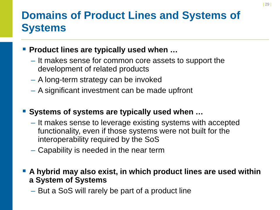
Product lines are typically used when … – It makes sense for common core assets to support the
development of related products – A long-term strategy can be invoked – A significant investment can be made upfront Systems of systems are typically used when …
– It makes sense to leverage existing systems with accepted functionality, even if those systems were not built for the interoperability required by the SoS
– Capability is needed in the near term
A hybrid may also exist, in which product lines are used within a System of Systems – But a SoS will rarely be part of a product line
| 29 |
Domains of Product Lines and Systems of Systems

Virtual – No central management – No centrally agreed upon purpose for the SoS
Collaborative – Components interact voluntarily (no central management) – Have agreed upon central purpose
Acknowledged – Systems engineering manager/team in place – Shared objectives – Individual systems retain their own funding, ownership, and
management Directed
– SoS built and managed to fulfill specific purposes – Central management over individual component systems
| 30 |
Types of SoS in the DoD Today
**SoS Categories come from DoD Systems Engineering Guide for Systems of Systems
| 31 |
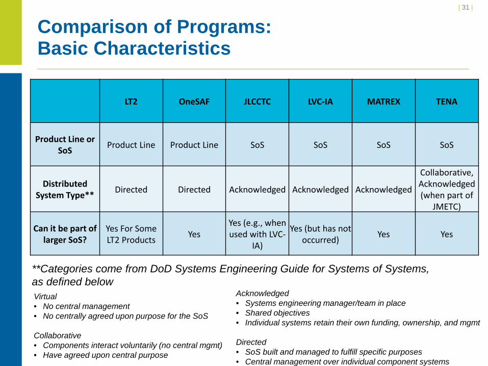
Comparison of Programs: Basic Characteristics
LT2 OneSAF JLCCTC LVC-IA MATREX TENA
Product Line or SoS Product Line Product Line SoS SoS SoS SoS
Distributed System Type** Directed Directed Acknowledged Acknowledged Acknowledged
Collaborative, Acknowledged (when part of
JMETC)
Can it be part of larger SoS?
Yes For Some LT2 Products Yes
Yes (e.g., when used with LVC-
IA)
Yes (but has not occurred) Yes Yes
**Categories come from DoD Systems Engineering Guide for Systems of Systems, as defined below Virtual • No central management • No centrally agreed upon purpose for the SoS
Collaborative • Components interact voluntarily (no central mgmt) • Have agreed upon central purpose
Acknowledged • Systems engineering manager/team in place • Shared objectives • Individual systems retain their own funding, ownership, and mgmt
Directed • SoS built and managed to fulfill specific purposes • Central management over individual component systems

| 32 |
.
Comparison of Programs: Governance (1 of 2) LT2 OneSAF JLCCTC LVC-IA MATREX TENA
Central Management Total Total Total for some
systems, sys eng for others
Systems Engineering
Aspects
Total for some sys, sys eng for others
Connectivity Aspects
Infrastructure Development
Control? Yes
Yes, but includes integration of
external mods* No No Some Yes
Individual System/Component
Control? Yes
Yes, but includes integration of
external mods*
Yes, but includes delivery of
external capabilities
No Some No
Modification Requesters (may
lead to requirements)
User Proponents, End
Users, Developers
User Proponents, End Users,
Developers*
User Proponents, End Users,
Developers, SE
User Proponents, End
Users, Developers, SE
SE, User Proponents, End
Users, Developers
User Proponents, End Users
Requirements Definition and Management
Core Asset Working Group
(CAWG)
TRADOC Program Office’s User
Feedback Review Board (UFRB)
Requirements Control Board
(RCB)
Requirements Control Board
(RCB)
M&S SWG, Systems
Engineering Review Board
(SERB), FOM WG
Architecture Management Team (AMT), JMETC Users
Group
Requirements Decision-Maker
Core Asset Change Board
(CACB)
TRADOC Program Office (TPO)
Configuration Control Board
(CCB)
Configuration Control Board
(CCB)
MATREX PMO, MATREX Board of Directors (BoD)
Architecture Management Team (AMT)
Translator of Capability
Objectives**
Core Asset Working Group
(CAWG)
Engineering Configuration
Control Board (E-CCB)
Systems Engineer M&S SWG, SERB,
FOM WG
TENA Software Development Activity (SDA)
** PM has ultimate authority for this role, in collaboration with identified organizations
* OneSAF source code gets released to community, and changes made to the software can be considered for inclusion in the OneSAF baseline

| 33 | Comparison of Programs: Governance (2 of 2) LT2 OneSAF JLCCTC LVC-IA MATREX TENA
Data Exchange Model(s) CTIA Object Model
Simulation Object Runtime Database
(SORD), Military Scenario Definition Language (MSDL)
Federation Object Models (FOMs),
Master Enumerations, OBS
JLCCTC Entity Resolution Federation (ERF) 6.0
FOM, CTIA Object Model
MATREX FOM; TENA Object Models, SORD,
DIS via ProtoCore
Multiple TENA Object Models
Standards Guidance
Standards in Large Portal Repository, including but not
limited to CTIA, FASIT, and LTEC
Product Line Architecture
Specification (PLAS), Codeveloper Guidelines
HLA, DIS, Security Lockdown Compliance
HLA, DIS, CTIA, SIMPLE, SECORE, Radiant Mercury
Cross-Domain Solution
SE tool (SDD) managed architectural guidelines,
HLA 1.3 NG, via ProtoCore (HLA 1516,
DIS, TENA, SORD)
TENA
Risk Management
Org
Core Asset Working Group (CAWG)
PM OneSAF’s Integrated Product
Team (IPT) SE Risk Management
Working Group Systems Engineering Review Board (SERB)
Architecture Management Team
(AMT)
Integrators and Testers Developers, Users Developers, Users SE, Developers, Users
Designated Test Team, Users (SMEs at Validation
Events)
Designated Test Team, Developers
Developers, Designated Test Team
Integration and Test Events
System Integration Test and Government
Acceptance Test for Each Product
System Integration Test, User Assessment
Baseline (UAB), Validation Event
Integration Event (IE), Validation Event (VE), Maintenance Release
Test (MRT), Operational Readiness
Event (ORE)
User Assessment, Functional Verification,
Operational Accreditation
Thread Test, Vignette Test, Operational
Readiness Exercise Informal
Fielding Approach
Each Product Team Delivers and Installs at
User Sites (Products installed
independently)
Deliver software and instructions to user
sites; user installs and configures based on
their needs
Deliver software and instructions to fielding
team (CTS); fielding team installs
Fielding Readiness Review, On-Site Delivery and Installation, On-Site Government Acceptance
Test
Users download MATREX tools from web
site or request DVD, then install ; M&S
distributed separately
Users download software and manuals
from web site, then install
Post-Fielding Support
Help Desks (one centralized and one for
each product); Warfighter Focus used
to Track Issues
Help Desk, Product Line Updates,
Customer-funded on-site support
PTR Management Process, Patch
Management, Web Portal (future)
NA
E-Mail reflectors, Phone Support, Customer-
funded extensive support
TENA Help Desk (middleware), JMETC
Help Desk (Connectivity), Middleware Updates
Major Release Frequency Varies by Prod. Team 12-18 months 12-18 months 2 year 6 months 2-3 years
Minor Release Frequency Varies by Prod Team 6-8 months 6 months None None 6-12 months

| 34 |
.
Comparison of Programs: Artifacts (1 of 2)
LT2 OneSAF JLCCTC LVC-IA MATREX TENA
Architectural Artifacts
Product Line Architectural
Framework (PLAF), Common Training Instrumentation
Architecture (CTIA), Live
Training Engagement Composition
(LTEC), Future Army System of
Integrated Targets (FASIT)
Product Line Architecture
Framework (PLAF)
SoS Architecture, SoS Policy
DODAF Diagrams, Build
Configurations (for AVCATT, CCTT,
HITS, JLCCTC, and OneSAF), DIACAP
templates
Systems Engineering
Management Plan (SEMP),
Architectural Strategies, DODAF
views
TENA Architecture
Reference Document
Requirements Artifacts
Product Line Requirements Specification
(PLRS), DOORS Database,
Operational Requirements
Document (ORD), DATR
Product Line Requirements Specification
(PLRS), Formalized requirements as
part of TPO process, OneSAF
Component Contract, DOORS
(previously)
Capability Production Document (CPD),
Requirements / Rough Order of Magnitude (ROM) Workbook, Integrated Task List
(ITL)
ViTech CORE Repository, Redmine,
Integrated Task List (ITL), DOORS
(future), MS Office Products
System Requirements
Specification (SRS), Technical Insertion
Process Documentation
Architecture Management Team (AMT) tracking lists

| 35 |
.
Comparison of Programs: Artifacts (2 of 2)
LT2 OneSAF JLCCTC LVC-IA MATREX TENA
Design and Development
Artifacts
Interface Control Document (ICD),
Software Subsystem Design (SSD), Component
Agreement, Service Level Agreement
Conceptual Model, Knowledge
Acquisition / Knowledge Engineering
(KA/KE) Products, Software
Subsystem Design (SSD)
Technical White Papers, Interface
Control Documents (ICDs), Event Trace
Diagrams, SoS Architectures, SoS
Policy
LVC-IA Interface Control Document
(ICD), System/Subsystem Specification (SSS)
System Design Description (SDD), Modeling Design Decisions (MDD),
System/Subsystem Specifications
(SSS), Federation Agreements
Document (FAD)
Architecture Management Team (AMT)
design presentations
Integration and Test Artifacts
Component Test Procedure
System Integration Plan (SIP), V&V Plan, T&E Plan
Integration and Test Plan, Integration
Readiness Review Checklist, Federation Operations Manual,
Way Forward Briefings (limitations and workarounds),
Software Problem Reports (SPR)
Database
Test and Evaluation Plan
(TEP), Thread Tests, Vignette
Tests, Test Procedures
Test Plan, Advanced Testing
Capability test cases and reports
N/A

| 36 |
.
Comparison of Programs: Tools (1 of 2)
LT2 OneSAF JLCCTC LVC-IA MATREX TENA/JMETC
General Collaboration
Tools
LT2 Portal, Gears (for variation management)
OneSAF Web Site JLCCTC SharePoint LVC-IA Portal MATREX Integrated
Development Environment (IDE)
TENA Web Site, TENA Integrated
Development Environment
(TIDE)
Requirements Tools
DOORS DOORS, MS Office Products
PTR Tracker (NSC maintained), MS
Excel
ViTech CORE, Redmine, DOORS
(future)
System Design Description (SDD) via MATREX IDE,
(DOORS previously used)
Design and Development
Tools**
Varies by product Various Composer tools, RT Tool
Visio (for SoS architecture) ,
Event Studio (for vignettes),
Integrated Task List
MS Office Suite, Visio (for arch.)
ProtoCore Gateway Builder
Integration and Test Tools
Varies by product Performance Modeling Tool,
Network Loader Tool , Benchmark
Tool, SORD Inspection Tools
Simulation Interoperability
Test Harness (SITH), SPR Tracker
(SharePoint), Federation
Management Tool Reloaded (FMT-R), Joint Enumerations
Cross-Checker (JECC), Perf Logger
Joint Simulation Protocol Analyzer (JSPA), Redmine
(for SPR tracking)
Advanced Testing Capability (ATC)
TENA Test Harness, Interface Verification Tool (IVT), WireShark,
TENA Protocol Dissector, Joint Interoperability
Modular Evaluation System
(JIMES)
** Design and development tools shown here do not include the software compilers and source code CM tools

| 37 |
.
Comparison of Programs: Tools (2 of 2)
LT2 OneSAF JLCCTC LVC-IA MATREX TENA/JMETC
Scenario Development
Tools
Scenario Development
Tool, Range Data Editor
Military Scenario Development Environment
(MSDE), Environment
Database Generation
Environment (EDGE)
Joint Tactical Data System
(JTDS), WARSIM SGEN Tools
Joint Remote Client (JRC), MSDE
(w/ OneSAF), EDGE (w/ OneSAF),
Portable Flight Planning Software
(PFPS)
Military Scenario Development Environment
(MSDE), Configuration and
Static Analysis Tool (CSAT)
Order of Battle Services (OBS),
ScenGen
Data Collection and Analysis
Tools
Observation Lite, Event Log HITS,
Report Generator Tool, Bookmark
Tool
Data Collection Specification Tool
Performance Tools, Simulation Interoperability
Test Harness (SITH)
Joint Simulation Protocol Analyzer
(JSPA) , Binary Capture Tool
hlaResults, Joint Digital Collection,
Analysis, and Review System
(JDCARS), Starship Software
Product Line
SIMDIS TENA Plugin, Reflect,
Joint Digital Collection,
Analysis, and Review System
(JDCARS)
Execution Preparation/ Initialization
Range Tracking Admin Tool,
Embedded Battle Roster
System Configuration and
Asset Management Tool
(SCAMT)
Joint Enumerations Cross-Checker
(JECC)
Synthetic Environment Core (SE Core) Master Entity List (MEL)
Tool
Configuration and Static Analysis
Tool (CSAT)
Starship
Execution Monitoring and
Control Tools
EXCON, Exercise Assistant,
Playback, Replay, Alarm and Alerts
Management & Control Tool, Federation
Management Tool, Stealth Tool
Federation Management Tool
Reloaded (FMT-R), WARSIM
Virtual Control
LVC-IA EXCON, SIMDIS
hlaControl, Starship Software
Product Line
Starship, TENA Console, TENA
Video Distribution System

When a complex simulation-based system is first developed, a key early decision is whether it will use a product line approach or an SoS approach – Relevant factors for this decision include: Anticipated lifecycle of the required solution Date at which an initial capability is needed Resources available for the initial planning and development Existing systems or components that can meet any of the overall system
requirements – If the system is expected to be around for a long time and a
program can afford the initial investment, then a product line approach may be better since long-term savings can outweigh the initial cost
– If the system is only expected to be around for a few years, or if a capability is needed very soon, then creation of a System of Systems out of existing applications may be best
– This decision affects the entire life of the program!
| 38 |
.
Creating a New Complex Simulation-Based System (1 of 2)

As with any acquisition program, the initial requirements must be clearly defined – Supports the previously mentioned decision of a product line or
SoS approach – May be satisfied through the development of new systems or
components, and/or through the identification of existing systems or components that can be incorporated
– Will lead to development of an initial architecture The initial architecture must be documented accurately and
thoroughly to support future evolution of the simulation-based system – This is especially critical for a product line, for which a Product Line
Architecture Framework defines the rules by which all developers must play
| 39 |
.
Creating a New Complex Simulation-Based System (2 of 2)

The product line or SoS should be managed as an entity in and of itself Standards should be identified, established, publicized, and
enforced to facilitate development and integration of the necessary components – The rigorous management, development, and adherence to
architectures, specified by architectural artifacts, are critical to all complex simulation-based systems
– While individual systems or individual components may use their own software approaches internally, their interfaces to other systems or components must follow architectural specifications.
It is critical to align acquisition strategy with implementation approach – Example 1: In a product line, because of the desire for common core
assets, separate contractors should not be tasked with work that will result in redundant functionality
– Example 2: In a SoS, if new or modified functionality requires changes to more than one system, it is imperative that all systems are funded appropriately
| 40 |
.
General Best Practices for Both Product Lines and SoS

To be successful, both product lines and systems of systems must invest in O&S for the following: – Systems engineer to manage the program lifecycle and new feature
requests – Technical teams for development, integration, and testing to include
periodic updates of new features – Post-fielding support Team in place to provide technical support and collect feedback Developers on contract to resolve issues quickly
In addition, the sites that employ complex simulation-based systems may also require dedicated staff for: – Technical support for executing and upgrading the distributed
simulation system – Scenario development – Data analysis
O&S costs can be reduced by usage of tools that allow operations to be conducted more efficiently – Example: automated test tools that allow testing of new functionality
without the full suite of systems in place
| 41 |
.
Operations and Support (O&S) for Product Lines and SoS

The product line should have a single, authoritative manager and funding source – A systems engineer should be appointed for product line
management, while separate managers may also exist for the products and core assets
– The command hierarchy should be structured to allow the overall manager of the product line to decide what changes to the core assets are best for the overall product line
– Budgets for the product line components should include some funds set aside for unanticipated changes required for the product line
Management of the product line must include both management of the core assets and management of the products – Relationships between core assets and products must be well
understood Changes to a product require the modification or introduction of one or
more core assets Changes to core assets effect all the products in which they are used
| 42 |
.
General Best Practices for Product Lines (1 of 4)

Development and maintenance of a Product Line Requirements Specification (PLRS), Product Line Architecture Specification (PLAS), and Product Line Architecture Framework (PLAF) are key for allowing new products to be incorporated into the architecture – The PLRS identifies core assets for use in multiple products This requires a long-term vision of how each core asset will be used with
current and future products – The PLAS defines system compositions, products and components
within the product line – The PLAF provides a view of elements in the PLAS It organizes and categorizes system compositions, products and
components Identifies functionally relevant components that can form the building blocks
for higher-level functionality – To ensure that developers adhere to product line requirements, the
program may: Put specific language into contracts to ensure that developers participate in
product line governance Provide training to industry
| 43 |
.
General Best Practices for Product Lines (2 of 4)

At the onset of a product line, the program manager must make a business case for this approach – As the product line will require a significant initial investment,
getting buy-in from the funding organization is critical – Stakeholders may become impatient until they see results, so the
so the program manager should also consider demonstrating some core functionality early on
– To bolster the business case, the program should also collect metrics (e.g. lines of code, number of problem reports resolved, time to integrate new components)
| 44 |
.
General Best Practices for Product Lines (3 of 4)

Variation management is essential for ensuring that any changes to the PLRS, to a product, or to a core asset result in modifications to the dependent systems that have an overall positive impact – Changes to PLRS, product, or core asset may, in turn, require
changes to dependent systems – If not done correctly, these changes may “break” other systems
When product variations are known and can be specified, the development team should create and field the required products When product instances are expected to contain large
variability that cannot be anticipated by the developer, it may be best to deliver products that can be composed and configured by the user
| 45 |
.
General Best Practices for Product Lines (4 of 4)

The SoS should be managed as an entity in and of itself – Establishment of a SoS Engineer – Incorporation of systems engineering processes
The evolution of a SoS requires a battle rhythm for evolution – Near term 1-2 year cycles that result in fielding new versions – Long range 5-7 year “backplane” planning – Reevaluation of requirements, technologies, and current state of
the SoS at the top of each cycle System synchronization is the job of the SoS Engineer
– Replan throughout the cycle to resynchronize as inevitable slips or priority changes occur
– Capture resultant SoS and shortfalls to: Ensure testing is focused on what is actually delivered Capture shortfalls that need to feed back as potential requirements for
the next cycle
| 46 |
.
General Best Practices for SoS (1 of 2)

The SoS should be decomposed into functional areas that can be decoupled from the rest of the SoS to the extent possible – This allows work on different functional areas in parallel within a
cycle – Changes in one functional area should have no or limited impact on
the rest of the SoS – SoS Engineer should plan individual system delivery and SoS
integration activity in functional area lanes The design and documentation of the SoS should be modified at
each cycle – This includes conceptual models, SoS composition, infrastructure,
and data exchange model Systems engineering processes are needed for each phase of
the SoS lifecycle, as well as for the conduct of events that employ the SoS
| 47 |
.
General Best Practices for SoS (2 of 2)
Subsequent slides contain some of the best practices for: – Managing the maintenance and evolution of a complex simulation-
based system Requirements definition Converting product line or SoS requirements into individual component
requirements or individual system requirements, respectively Defining standards and providing guidance for implementing changes Testing and validating the complex simulation-based system Fielding the complex simulation-based system
– Usage of a complex simulation-based system Pre-event activities Initialization Execution Data collection Post-event activities
The information on the ensuing slides is relevant to both product lines and systems of systems, unless explicitly stated otherwise
| 48 |
.
Specific Best Practices

Users, testers, and developers should have a mechanism for submitting problem reports Sponsors and other stakeholders should have a mechanism for
defining high-level direction Users groups provide a useful forum for identifying issues and
their associated priorities There must be a clearly defined process for narrowing down
requirements to fit within funding constraints A systems engineering team should manage a tracking system
for all requirements and their associated status – This requires collaboration with users, developers, and testers
For product lines, requirements outline should be reflective of the product line architecture – Supports the requirements allocation process – Supports explicit recognition of common core assets
| 49 |
.
Managing the Maintenance and Evolution of a Product Line or SoS Best Practices for Requirements Definition

For each requirement, the systems engineer works – With persons who submit a problem report or enhancement request to fully
understand the issue – With users to understand the priority – With developers to understand possible solutions
For a product line, the systems engineer works with the product developer to determine which core assets require modification to achieve the desired capability
For a SoS, the systems engineer manages the development of one or more concepts for meeting a SoS requirement – For each option, developers of each system that would be added or changed must
provide a high-level design and ROM – Interoperability challenges must be overcome via detailed dialogue between
developers and the systems engineer Use of a common object model and agreed upon protocol is a small part of this More engineering is required to work out a meaningful data exchange
– Semantic understanding of object representation (meaning, why and when) – Federation/SoS runtime agreements (update frequency, dead reckoning) – Fidelity and resolution matches across simulations – Data correlation (terrain, weather, damage effects)
– Ideally, a design meeting attended by all stakeholders can be conducted to assess each change proposal
| 50
Managing the Maintenance and Evolution of a Product Line or SoS Best Practices for Converting Product Line or SoS Requirements into Requirements for Individual Components/Systems (1 of 2)

Determination of whether or not to resolve an issue in the next release depends on its priority, risk to the rest of the system, and resources required to implement the change – The solution should meet the user requirement while minimizing
complexity – To reduce cost of collaboration, it is best for a solution to use
components/systems that are already part of the product line / SoS For changes that will proceed, specific tasking is documented
for each of the individual components/systems being changed or added – For an SoS, this should also include a schedule for the test and
integration of the change to the SoS – For a product line, the modification of core assets should include an
assessment of how it impacts each product that uses the core asset, as well as a test schedule for the effected products
| 51
.
Managing the Maintenance and Evolution of a Product Line or SoS Best Practices for Converting Product Line or SoS Requirements into Requirements for Individual Components/Systems (2 of 2)
Interfaces between individual systems must be well documented, using some combination of the following: – Data exchange model – Interface Control Document – Sequence diagrams – Vignettes that consist of event trace diagrams for new functionality – Use cases
Use cases drive decisions associated with deployment and composability – A user might select an “as is” representation of an object or
behavior, or the user may compose the object or behavior – If the simulation is to be composable, then the system must be
flexible enough to support this, and tools must be provided to the user for composition
| 52
.
Managing the Maintenance and Evolution of a Product Line or SoS Best Practices for Defining Standards and Providing Guidance for Implementing Changes (1 of 2)

For a product line, the interface of product components should be documented in a Product Line Requirements Specification (PLRS) – Complexity of the PLRS should be carefully managed Low complexity fewer burdens on core assets, but more constraining
to functionality that can be achieved High complexity greater flexibility for new functionality, but increases
difficulty of creating and maintaining core assets Tools can facilitate implementation, such as:
– Code generation tools that are based on the data exchange model and the middleware protocol This is especially helpful for SoS environments that contain legacy
systems that were not originally built for interoperability with other systems in the SoS
– Repositories of architecture specifications and other standards
| 53
.
Managing the Maintenance and Evolution of a Product Line or SoS Best Practices for Defining Standards and Providing Guidance for Implementing Changes (2 of 2)

For an SoS, integration events should be conducted to assess functionality and interfaces associated with each new SoS version – Prior to large integration and test events, the systems engineer should
publish test objectives, data model, and any changes to the infrastructure
– The systems engineer may provide automated tools to allow individual components to test interfaces with surrogate software (example: MATREX’s ATC tool, JLCCTC’s SITH tool)
– The validating user should provide SoS test cases – The systems engineer should work with the developers ahead of time
to ensure what new functionality is mature enough for assessment at the formal test event The system engineer may conduct readiness reviews in which small tests are
conducted at individual sites For a product line, separate testing can be conducted to assess
functionality of each product – Each product may be released individually, so it is not always
necessary to test the entire product line
| 54
.
Managing the Maintenance and Evolution of a Product Line or SoS Best Practices for Testing and Validating the Product Line or SoS (1 of 3)

Testing should be conducted by an independent agent – Avoids any conflict of interest – Interoperability issues can be assessed fairly, without trying to
make any particular system or component look better For simple issues, can lead to quick modifications or workarounds if the
neutral party is empowered to provide on-site solutions, in collaboration with the developers representing the different components or systems
Integration testing incorporates increasing complexity (number of systems, number of interfaces) prior to system-wide integration and formal testing Formal testing may consist of a series of events of increasing
importance: – Integration event – Validation event – Government Acceptance Test
| 55
.
Managing the Maintenance and Evolution of a Product Line or SoS Best Practices for Testing and Validating the Product Line or SoS (2 of 3)
During formal test and integration events, the following should occur: – Training should be provided to testers from the developers and
possibly from the systems engineer – At the start of the event, known problem areas and workarounds
should be communicated to avoid wasting testing time – Testing should follow well-documented procedures, and pass/fail of
individual steps should be based on well-defined acceptability criteria – Problem reports are generated by testers and tracked by the systems
engineer – In addition to functional testing, performance testing should be
conducted to identify any bottlenecks in the product line or SoS – Regression testing should also be conducted to ensure that prior
functionality still works correctly After final test:
– Systems engineer assesses results and determines what will be included in the product or SoS version that gets released
| 56
.
Managing the Maintenance and Evolution of a Product Line or SoS Best Practices for Testing and Validating the Product Line or SoS (3 of 3)

For a product line, individual products can be fielded at separate times to the sites that will use them – The systems engineer should track which versions of which
products have been installed at which sites For an SoS, the entire SoS gets fielded
– The systems engineer should track where different versions of the SoS have been fielded
Based on the complexity of a product or an SoS, different fielding approaches have worked: – Deliver software and documentation to site; user installs – Designated fielding team goes to site to deliver and install system – Designated fielding team conducts on-site survey, installs software
on-site, and then conducts a formal test at the site
| 57 Managing the Maintenance and Evolution of a Product Line or SoS Best Practices for Fielding the Product Line or SoS (1 of 2)
The program must determine the type of software delivered to the user – If users are empowered with developing representations of new object types or
new behaviors, then the delivered software must include appropriate tools for composing new objects and new behaviors Mechanisms should also be in place to leverage the composition work from different
users for contribution to the overall program For instance, programs for which different platforms can be defined by users should
maintain a repository of these representations, so that they can be reused within the user community
– A program may also want to release source code to users and allow them to make changes in this case, the program should have a mechanism to assess modified software
modules for possible integration into the software baseline It is critical that technical support be provided to the user
– This is true for post-fielding support, as well as for installation support when the product or SoS is not being installed for the user site
– This can come from the developer and the systems engineering team The systems engineer should also have a mechanism for collecting user
feedback after the system has been fielded Mechanisms should exist to provide maintenance releases or patches when
critical problems are discovered
| 58 Managing the Maintenance and Evolution of a Product Line or SoS Best Practices for Fielding the Product Line or SoS (2 of 2)

First, the objectives for the event should be clearly defined Next, to meet the objectives, the concept of usage must be
agreed to at a high level, including: – Timeframe and geographic area to be represented – Military entities (platforms, organizational units) to be represented – Whether the entities will be represented in live, virtual, or
constructive simulations – Missions and associated OPTEMPO – Events to occur in the execution – Live platforms and C4I systems to be stimulated – Data to be collected
For composable environments, the specific set of components or systems to be used must be decided based on the usage concept, and tools must be available for the composition
| 59
.
Managing the Usage of a Product or SoS Best Practices for Pre-Event Activities (1 of 2)

Composition may also be required for object and behavior representation – Scenario developers should first determine if the desired representation of an
object or behavior already exists, or is close enough to meet the objectives of the event
– If not, the closest representation of the desired capability should be identified and then modified to reduce composition time
– If a system is developed with the flexibility for a user to compose objects and behaviors, then tools should exist to facilitate the composition.
The use concept also drives the installation and configuration required for the complex simulation-based event – The number of instances of a simulation and the configuration of those
instances depends on the required types and quantities of entities, the events to be injected, and the C4I systems for which data is generated
To reduce scenario creation time, scenario developers should – Leverage information from existing databases – Use automated scenario development tools, if available
To the extent possible, automated tools should identify any problems with scenario data and with data interfaces prior to investing time in event execution and analysis
| 60
.
Managing the Usage of a Product or SoS Best Practices for Pre-Event Activities (2 of 2)

For environments in which the ordering of component initialization is important, the sequence of initialization events should be well documented – This requires an understanding of the dependencies among
systems – A system cannot be invoked prior to the invocation of another
system upon which it relies Mechanisms should exist to ensure that all components are
successfully initialized before proceeding with execution – All individual systems are up and ready – Data collection is configured to record data that meets the
objectives of the run
| 61
.
Managing the Usage of a Product or SoS Best Practices for Product/SoS Initialization

Simulation control should be managed by one or more persons to: – Direct the starting and stopping of components – Manage injection of events – Save and restore data (if applicable)
Due to the complexity of distributed simulation environments, monitoring tools should be used to check the health and status of all components – Ensure needed processes are running – Check data unique to the product or SoS, as in the following
examples: Ensure that individual systems instantiate the correct types and numbers of
objects Ensure data passed over infrastructure conforms to standards Ensure C4I systems are continually updated with simulation-generated data
– Monitor computing resources (CPU, disk usage, etc.)
| 62
.
Managing the Usage of a Product or SoS Best Practices for Product/SoS Execution
To support after-action analysis, data should be automatically recorded – Data that passes through a common infrastructure can be
captured by a specialized data collection system – Individual components may also capture data internally, but they
should use a consistent time stamp to ensure the data can be assessed along with federation-wide data, if necessary
Some real-time data analysis for an execution in progress can be useful for ensuring a run is proceeding normally or for taking remedial action
| 63
.
Managing the Usage of a Product or SoS Best Practices for Product/SoS Data Collection

Captured data should be archived to prevent information loss Participants should provide feedback while knowledge from the
run is still fresh: – Feedback on operational aspects of the scenario – Feedback on how the technical systems performed – The systems engineer may arrange to do this in a “hot wash”
event in which all participants meet at event completion Based on feedback from a run, identify limitations and
workarounds to be addressed or documented
| 64
.
Managing the Usage of a Product or SoS Best Practices for Post-Event Activities

Management of artifacts using basic Microsoft Office products is error-prone An automated, data-driven approach is recommended
– Establishes associations between different elements Example: links between requirements, software design, and test plans Associations allow for reuse via pointers to information (updates to
information in one place updates all references) Can support automatic generation of artifacts via data queries
(Examples: SSS, pub/sub matrix) Allows for workflow management by the data-driven system as
opposed to manually – All users access the same version of the product line or SoS,
reducing configuration management difficulties – Ensures unique IDs for PTRs, requirements, etc.
| 65 |
Management of Artifacts