Embed Size (px)
Citation preview
1
-1-
Introduction and Background Introduction
In a relatively short period of time, the Unified Modeling Language (UML)
has emerged as the software industry’s dominant modeling language (Kobryn,
1999). This thesis will provide how to model an Object-Oriented Internet
Application’s functionality using the UML. Developers, analysts, designers,
managers, and professors who are interested in the development of large or
small-scale Internet applications will be able to use this thesis as a quick
reference.
The UML has changed the way computer applications are developed.
The introduction of UML has offered system developers, designers, and project
managers a unified way to communicate about a system. As a result, the UML
provides a simplified Application Life Cycle Development (ALCD), as well as a
quick and efficient development process.
In this project, the development of an Object-Oriented Internet/Intranet
Application (OOIA): University Scheduling and Information System (UNISIS) will
take place using of the UML. To develop UNISIS based on the UML model, the
technologies of choice will be Microsoft’s Visual Basic (VB), VBScript and Active

2
Server Pages (ASP), and SQL Server. This system will allow students of a
university to register for, and make changes to their courses, and/or personal
information. In addition, the chair of a specific department will be able to
complete semester course schedules and manipulate course and instructor
information, while instructors will be able to request schedules, view course
rosters, and change personal information using the system. The Internet will be
the medium of use for completing these transactions.
This project neither attempts to redefine the UML process nor Object-
Oriented Development Principles (OODP), but demonstrates how the UML can
be used to conduct Object-Oriented Design and Analysis (OODA) and apply it to
the development of a real-life OOIA.
Significance of using The UML
Developing a software system requires writing multiple programs to
achieve multiple objectives. A computer program often stands alone to solve a
user’s specific problem. However, most computer programs are part of a larger
system (Farrell, 2002). The UML allows each programmer, even if they are
programming different parts of the system, to view a common model of the
system before proceeding to write any code. This would enable them to write
code that would enable a seamless integration between programs.
This thesis will focus on representing a graphical depiction of an OOIA,
utilizing the UML’s main diagrams, and then converting those diagrams into a
3
real-life application. This graphical depiction will give a picture of the system’s
characteristics and functionality before development takes place.
The UNISIS Approach
Today, computer applications are developed for both desktops and
Internet. As the use of the Internet becomes more widespread around the world,
new applications are developed, and legacy systems are modified for use via the
Internet. As a result, there are also new ways of designing applications. In the
early days of the Internet, web pages were static. This meant that the
information remained the same until the programmer updated the HTML pages.
Today, the use and need of Dynamic Database-Driven Internet Application
(DDDIA) has become a natural way of life. DDDIA affords the ability to change
content for an application without editing the HTML pages.
VB, ASP, and Microsoft Access are good technologies for building DDDIA.
ASP enables the creation of dynamic HTML pages. VB allows the creation of
compiled objects, which enhances the performance of the application. Microsoft
Access provides the back-end and storage of user data.
Validating the UNISIS Approach
In applying the UML to OOIA Development, UNISIS is first modeled with
UML diagrams and then used to aid in the programming of a complete Internet

4
Application. UNISIS™ will be installed and run on Microsoft Windows NT or
2000 Server. Internet Information Server (IIS) will be used for testing.
The UML Diagrams
The modeling of UNISIS will use the following UML diagrams:
• Use-case Diagrams: to model the functionality using actors and use-
cases
• Class Diagrams: the backbone of every object-oriented method, including
UML
• Package Diagrams: a subset of class diagrams
• Object Diagrams: test class diagrams for accuracy
• Sequence Diagrams: describe interactions among classes (i.e.,
messages exchanged)
• Collaboration Diagrams: represent interactions between objects as a
series of sequenced messages
• State-Chart Diagrams: model reactive objects, where states are triggered
by specific events
• Activity Diagrams: model workflow or business processes and internal
operations
• Component Diagrams: model the organization of physical software
components (i.e., source code, run-time code, .exe files)
5
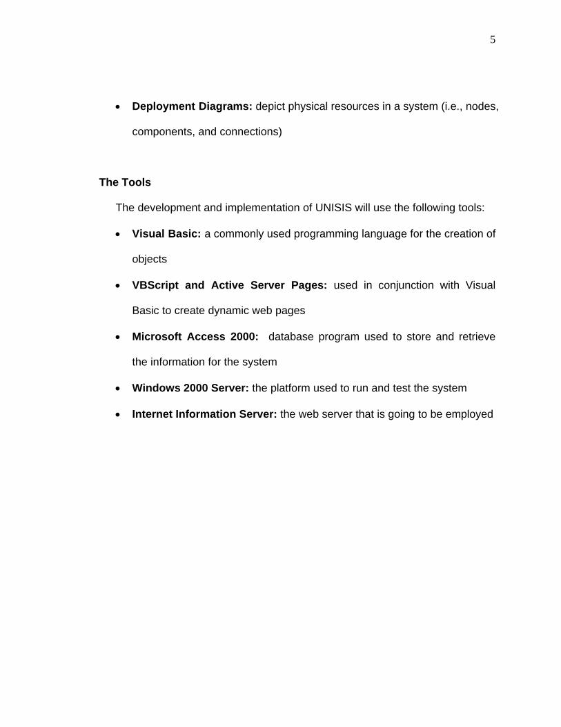
• Deployment Diagrams: depict physical resources in a system (i.e., nodes,
components, and connections)
The Tools
The development and implementation of UNISIS will use the following tools:
• Visual Basic: a commonly used programming language for the creation of
objects
• VBScript and Active Server Pages: used in conjunction with Visual
Basic to create dynamic web pages
• Microsoft Access 2000: database program used to store and retrieve
the information for the system
• Windows 2000 Server: the platform used to run and test the system
• Internet Information Server: the web server that is going to be employed
6
-2-
The Unified Modeling Language and Object-Oriented Programming and Development
Introduction
The UML was created because of the so-called method wars of the 1970s
and 1980s. During this time, developers were faced with a new era: the OOPD
era. As a result, new methods for analysis and design were needed. “The
number of object-oriented methods increased from fewer than ten to more than
fifty between 1989 and 1994. Many users of these methods had trouble finding a
language that completely met their needs” (Booch, 1999). After years of trying
and implementing different methods, Booch, Jacobson and Rumbaugh, finally
came up with a solution that became, and continues to be the accepted standard:
the UML.
What is The UML
“The Unified Modeling Language (UML) is a graphical language for
visualizing, specifying, constructing, and documenting the artifacts of a system-
intensive system” (Booch, 1999). The modeling language provides a visual
expression of the software system being developed. This is achieved by using

7
various UML notations and diagrams. To serve it’s purpose, a modeling
language has to allow concise expression of the essential aspects of the
software system being developed, while omitting irrelevant details (Selic,
Ramackers & Kobryn, 2002). More than likely, a system developed using UML
will use one of the popular object-oriented programming languages such as
SmallTalk, C++, or Java.
What the UML is not
Contrary to popular belief, the UML is not a programming language like
C++, VB, or Java, but it is used to support the development of a system using
one of those languages, or another language of choice. The UML does not
provide syntax as in a programming language, but it provides syntax in terms of
notations and diagrams visually defining the system.
The UML is not a visual programming language but a visual modeling
language. It is not a tool or repository specification but a modeling language
specification. It is not a process but enables processes (O’Reilly & Associates,
1998). The UML may be used in a variety of ways to support a software
development methodology, such as the Rational Unified Process (RUP), or
Extreme Programming (XP).
.

8
Utility of the UML
The UML is an evolutionary, general-purpose, broadly applicable, tool-
supported, and industry-standardized modeling language. It applies to a
multitude of different types of systems, domains, and methods or processes
(O’Reilly & Associates, 1998). OReilly & Associates continued to define the
strengths of the UML as:
As a general-purpose modeling language, it focuses on a core set of
concepts for acquiring, sharing, and utilizing knowledge coupled with
extensibility mechanisms.
As a broadly applicable modeling language, it may be applied to
different types of systems (software and non-software), domains
(business versus software), and methods or processes.
As a tool-supported modeling language, tools are readily available to
support the application of the language to specify, visualize, construct,
and document systems.
As an industry-standardized modeling language, it is not a proprietary
and closed language but an open and fully extensible industry-
recognized language.
Because the UML evolved primarily from various second-generation
object-oriented methods at the notation level, most practitioners of the UML
believe that it is only concerned with OO software-systems. In reality, the UML is
not simply a third-generation object-oriented modeling language but a "unified

9
modeling language" concerned with systems in general (Rumbaugh, Booch, and
Jacobson, 1999).
The success of the UML will be measured by its appropriate use on
successful projects. The UML does not guarantee success, but enables
practitioners to focus on delivering value using a consistent, standardized, and
tool-supported modeling language (Rumbaugh, Booch, and Jacobson, 1999).
The UML’s Main Diagrams
UML offers different types of diagrams, which would help system
designers, achieve their goals when designing a software system. The main
UML diagrams that are used in this thesis are use-case, class (package) and
object, sequence, collaboration, state-chart, activity, component, and deployment
diagrams. The remainder of this section provides a brief description of each
UML diagram.
Use-case Diagrams - Use-case diagrams model
the functionality of a system using actors and use-
cases (Rumbaugh, Booch, and Jacobson, 1999).
10
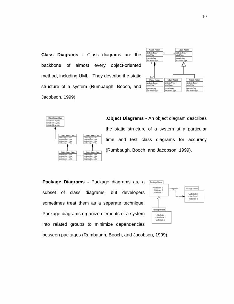
Class Diagrams - Class diagrams are the
backbone of almost every object-oriented
method, including UML. They describe the static
structure of a system (Rumbaugh, Booch, and
Jacobson, 1999).
.Object Diagrams - An object diagram describes
the static structure of a system at a particular
time and test class diagrams for accuracy
(Rumbaugh, Booch, and Jacobson, 1999).
Package Diagrams - Package diagrams are a
subset of class diagrams, but developers
sometimes treat them as a separate technique.
Package diagrams organize elements of a system
into related groups to minimize dependencies
between packages (Rumbaugh, Booch, and Jacobson, 1999).

11
Sequence Diagrams - A sequence diagram
describes interactions among classes in terms of
an exchange of messages over time (Rumbaugh,
Booch, and Jacobson, 1999).
Collaboration Diagrams - A collaboration
diagram represents interactions between objects.
This interactions in demonstrated as a series of
sequenced messages. Collaboration diagrams
describe both the static structure and the dynamic behavior of a system
(Rumbaugh, Booch, and Jacobson, 1999).
State-Chart Diagrams - State-chart diagrams
describe the dynamic behavior of a system in
response to external stimuli. State-chart diagrams
are especially useful in modeling reactive objects
whose states are triggered by specific events
(Rumbaugh, Booch, and Jacobson, 1999).

12
Activity Diagrams - Activity diagrams illustrate
the dynamic nature of a system by modeling the
flow of control from activity to activity. An activity
represents an operation on some class in the
system that results in a change in the state of the
system. Typically, activity diagrams model the workflow or business processes
and internal operation (Rumbaugh, Booch, and Jacobson, 1999).
Component Diagrams - Component diagrams
describe the organization of physical software
components, including source code, run-time
(binary) code, and executables (Rumbaugh, Booch,
and Jacobson, 1999).
Deployment Diagrams - Deployment diagrams
depict the physical resources in a system,
including nodes, components, and connections
(Rumbaugh, Booch, and Jacobson, 1999).
13
When to use the UML
The UML is used to communicate the knowledge of a software system to
a number of different people. The UML was purposefully designed to be non-
technical so that developers, consumers, and implementers (programmers) could
all “speak the same language.” If both managerial and technical teams can
agree on what a system should do, chances improve that the final product will be
useful (Farrell, 413).
Object-Oriented Programming and Development
Object Oriented Development (OOD) came about in the 1970s. It was
based on the object-oriented paradigm and allowed for the programming, design,
analysis, testing and debugging of systems. This paradigm is supports the
notions of inheritance, encapsulation, and polymorphism etc. Object Oriented
Technology (OOT) grew tremendously during the 1980s with the emergence of
several more sophisticated programming languages, including C++, Objective-C,
and Eiffel. Jia (2000) stated, “despite its long history of development, only
recently has the object-oriented development approach matured and become
widely accepted by the mainstream software industry.”
OOD has become very popular in recent years. This has allowed
designers and programmers to produce software that is maintainable, flexible,
14
and manageable. In Object-Oriented Programming (OOP), a program is
structured as a collection of classes, where each class describes a type of object.
An object represents an entity - thing, person, or place - naturally
occurring in the program. In principle, OOP uses objects while allowing
programmers to reuse and debug code, which is a main advantage of this
methodology. Another positive consequence of OOP is that it provides security
and protection of data; when data elements are stored in a class, they are easily
protected. These and other pros of OOP and OOD will guarantee the continued
growth of OOPD within the software industry.
Along with objects, OOP also possesses other characteristics such as
methods and messages, abstraction and encapsulation, as well as inheritance
and polymorphism.
Objects, Instances, and Classes
In developing OO software systems, anything and everything becomes a
class. This means that a person can become a class, as can a building, since
they can be described by characteristics and properties. This will be
demonstrated in detail later in this chapter and in Chapter Four. A class is a
number of individuals (persons or things) possessing common attributes, and
grouped together under a general or ‘class’ name, a kind, sort, and division
(Oestereich, 1999). For example, imagine building a system for a college, and it
is required to store information on students. Students would become a class of

15
that system, which would be able to store the appropriate information (properties)
on each student.
An object is called an instance of that class. An instantiation of a class is
made when a new object for that particular class is created. An object is an
instance, which is present at execution time and allocates memory for its
instance variables. It behaves according to the protocol of its class (Oestereich,
1999). If you understand the concept of objects, it will be easier to understand
the concept of OOP.
Using the student example, we would have the class illustration in the
figure below. In this example and other documentation, both a class and an
object are illustrated by drawing a rectangular box with the name of the
class/object in the middle. The name of the Object is underlined, while the class’
is not.
Instance ofJohn Student
Instance ofObject Class
Object Class

16
What is going on
The diagram first demonstrates the illustration of a class and an object. It
then shows the relationship (instance of) between a class and an object. There
is a clear depiction of the relationship between the class and the object by using
the class “Student” and showing the object “John’ as an instance of the class
“Student.”
Attributes, Constraints, Messages and Methods Attributes and methods are critical in the development of classes.
“Attributes, also known as properties, describe the class, and the occurrence of
an attribute shows the existence of an object variable. Attributes are the
structure of objects: the components and the information or data contained
therein” (Oestereich, 1999).
Methods can be called actions or operations. They define what is to be
done with attributes within a class. For instance, using the example of our
‘Student’ class we would have a method called ‘AddStudent()’. This method is to
perform the action or operation of adding a new student to the system.
“Operations are the behavior of the objects. Commonly, the term operations is
used. However, sometimes the words ‘services’ or ‘methods’ are used”
(Oestereich, 1999).
Constraints are rules or protocols to be followed when dealing with
attributes. In order to maintain the consistency or integrity of data we derived a

17
set of constraints. Constraints are conditions, requirements, and rules that
objects must satisfy (Oestereich, 1999). For example, in order for a student to
enroll in college they must be over the age of 16 years. In this case, any student
less than 16 years would be denied admission.
A message in software development serves the same purpose as it does
in our lives. When we want someone to do something or want to communicate
with a person, we send him/her a message. In a similar way, messages are sent
in OOP. Objects are allowed to communicate with each other through the
passing of messages. These messages are usually in the form of parameters
and are passed along within the methods of an object. A pseudocode
implementation of the Student class for our Internet Application (IA) is shown
below.
Begin Class Student:
List of Attributes/Properties: Integer ID String Name String Address String Phone String Gender Integer Age
List of Methods: AddStudent() DeleteStudent(by ID) UpdateStudent(by ID) FindStudent(by name, by ID) End Class Student

18
What is going on
In the illustration above, we have a list of attributes for the student class
(‘ID’, ‘Name’, ‘Address’, ‘Phone’ and ‘Age’). These attributes represent the
information that we would like to store about a student. We also have a list of
methods. In three of these methods, messages are passed between them.
These messages or parameters tell each method how they should proceed. In
the first instance the ‘DeleteStudent()’ method is to locate and delete a student
by their ‘ID’. In the second instance the ‘UpdateStudent()’ method is to update a
student record also by student ‘ID’. Finally, in the third case the ‘FindStudent ()’
method is to locate a student using their ‘Name’ or ‘ID’. The use of messages in
these cases makes it a lot easier to perform the tasks requested by the objects.
Encapsulation
In an earlier section when it was explained that “one of the advantages of
OOP is that it provides security and the protection of data,” since data elements
are stored in a class they are easily protected. This is precisely what is meant by
encapsulation. Encapsulation allows for the hiding of data elements from outside
code. In OOP, we do not want unauthorized access to our properties. This is
what OOP is all about: preventing unauthorized access to class properties.
In encapsulation, the data is not physically available to the user of the
object. The object is available to the user, and data is available to that object.
When performing an action on an attribute you do not have to tell that object

19
what to do, or how to do it. Due to the protection of the data, the methods
already know what to do, thus only the object has knowledge about the
operations to perform.
Inheritance
Inheritance is a very important concept in OOP. Just as we inherit
property from our parents and grandparents, classes also inherit properties from
their parent classes (and so on). A parent class is a class that provides or lends
behavior to another class. “The class that bestows its properties is called the
SuperClass or base class, while the class that inherits something is called the
sub class” (Oestereich, 2002). To illustrate this, let us look at the following
example.
Consider this scenario: Two students applied to school, the first student
decides to attend school part-time, and the second decides to attend school full-
time. We therefore need to store information on the full-time student as well as
the part-time student. To avoid having to create separate classes for full-time
students and part-time students, we will create a base class ‘Student’, to store all
personal information on the students. We would then create sub-classes ”Full
Time Students” and “Part Time Students” to store the “Student ID” and “Status”
of the students along with other information that may be needed for each type of
student. These sub-classes would then inherit all the other properties of the
‘Student’ class including the attributes and methods of that class.

20
Student
Full-Time
Part-Time
What is going on
The ‘Student’ class is the parent or base class and the part-time and full-
time student classes are called the children or child classes. Note that though
the child class have access to all the properties and method of the parent class,
child classes can also have their own properties and methods, which can be
different from those of the parent class.

21
Polymorphism
Polymorphism, which means the ability to take on many forms, extends
OOP in that it allows methods to take on different forms. Polymorphism means
that an operation can behave differently in different classes (Oestereich, 2002).
Using our Student class example, the AddStudent() method is used to
illustrate the use of polymorphism. Consider the following code segment.
Begin Class Student : Public Methods: void AddStudent(char name, char address, int age);
void AddStudent(int ID, char status, char major, int crs);
End Class Student … Create an object S for our Student Class Students S S.AddStudent(“John”, “222 E 48th ST”, 20);
S.AddStudent(111, “Full-Time”, “CIS”, 34);
…
What is going on?
Here, in the Student class we have one method serving two different
functions. In the first instance the AddStudent() method is adding a new
student’s ‘Name’, ‘Address’ and ‘Age’ into the system. In the second use of this
22
method, it is adding the student’s ‘ID’, ‘Status’, and ‘Major’ into the system. It can
be fair to assume that the ‘Student’ class invokes the first use of this operation
and the second invocation of this method is done by the Full-Time or Part-Time
Class. The use of polymorphism and inheritance aids in the concept of code
reuse, which makes OOP easier and allows for the writing of shorter code.
Object-Oriented Systems Analysis and Design Applying the UML and modeling software systems is the focus of this
thesis. The production of an efficient software system depends on both systems
analysis and design.
Object-Oriented Systems Analysis
In performing OOA, special attention should be paid to the users. The
users are very important factors to consider when developing a large software
system. In addition, how the users will use the system should also be considered.
Use-case Analysis
The first step in carrying out the OOA is the use-case analysis. The
reader is going to see in Chapter Four how use-cases are used in the process of
carrying out the modeling of a system with the UML. A use-case is a scenario or

23
path followed by a user when he/she uses the system. The user of the system is
known as an actor (person or system).
Identifying the Actors
One of the main components of a system is the users of the system.
Without them, there will be no need for the system. First, the actors must be
identified. After the actors are identified, their roles in the system should also be
identified. Identifying the actors’ roles assists in the development of the use-
cases. For example, the role of the Instructors is to enter grades, and update
student rosters, which aids in determining that they will use the enter grades use-
case as well as the maintain course roster use-case.
Actors Roles
Students: Chair Person:
Instructors:
Registrar Personnel:
Admissions Personnel:
The System:
registering for clases, checking grades and
changing personal information
assigning the instructors to classes, making
the class schedule, determining class
availability and class size.
entering students’ grades and updating
course rosters.
maintaining the records of students, faculty,
and staff.
entering and updating student’s personal
information.
returning information to the users.
24
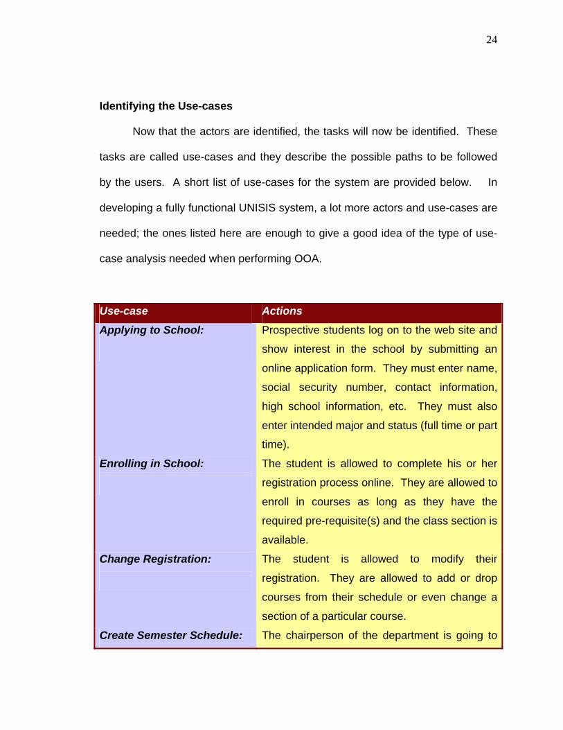
Identifying the Use-cases
Now that the actors are identified, the tasks will now be identified. These
tasks are called use-cases and they describe the possible paths to be followed
by the users. A short list of use-cases for the system are provided below. In
developing a fully functional UNISIS system, a lot more actors and use-cases are
needed; the ones listed here are enough to give a good idea of the type of use-
case analysis needed when performing OOA.
Use-case Actions
Applying to School:
Prospective students log on to the web site and
show interest in the school by submitting an
online application form. They must enter name,
social security number, contact information,
high school information, etc. They must also
enter intended major and status (full time or part
time).
Enrolling in School:
The student is allowed to complete his or her
registration process online. They are allowed to
enroll in courses as long as they have the
required pre-requisite(s) and the class section is
available.
Change Registration:
The student is allowed to modify their
registration. They are allowed to add or drop
courses from their schedule or even change a
section of a particular course.
Create Semester Schedule: The chairperson of the department is going to
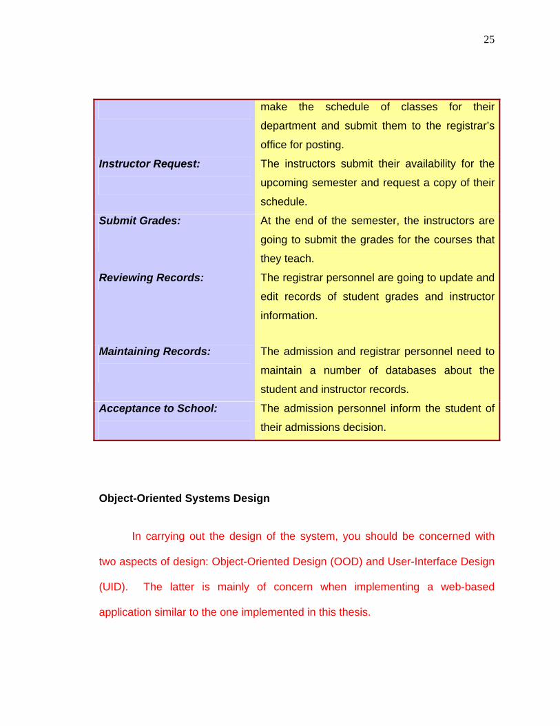
25
make the schedule of classes for their
department and submit them to the registrar’s
office for posting.
Instructor Request:
The instructors submit their availability for the
upcoming semester and request a copy of their
schedule.
Submit Grades:
At the end of the semester, the instructors are
going to submit the grades for the courses that
they teach.
Reviewing Records: The registrar personnel are going to update and
edit records of student grades and instructor
information.
Maintaining Records:
The admission and registrar personnel need to
maintain a number of databases about the
student and instructor records.
Acceptance to School:
The admission personnel inform the student of
their admissions decision.
Object-Oriented Systems Design
In carrying out the design of the system, you should be concerned with
two aspects of design: Object-Oriented Design (OOD) and User-Interface Design
(UID). The latter is mainly of concern when implementing a web-based
application similar to the one implemented in this thesis.

26
OO design is the process of modeling the program or software,
understanding the principal objects, and detailing how they will interact. OO
design is principally concerned with objects – things in the design that have both
properties (attributes) and behavior (actions or methods).
UID is the process of understanding how the user will interact with the
application: what do the pages (forms) look like, what buttons users click, what
widgets are displayed on the page and so forth.
Types of Architecture
They are two types of architectures that are used when designing web
applications: Two-Tiered Architecture, and Three Tiered or N-Tiered Architecture.
In Two-Tiered Architecture, there is direct communication between the browser
(client) and the system (web server/database server). In this type of scenario,
the user requests information from the server, and the server sends the
information back to the user as illustrated below.

27
Information request
In N-Tiered or Three-Tiered Architecture, there is no direct communication
between the user (client) and the system (web/database server). In this
architecture, the user requests information from the web server. The web server
then retrieves the requested information from the database server, which
subsequently forwards the information back to the client via the web server. This
is also known as client-server architecture, which is the architecture that will be
used in our UNISIS system.
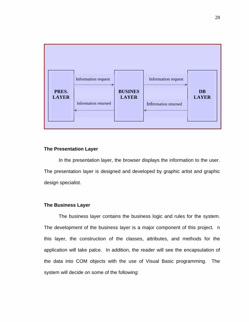
In the client-server model/architecture, the system is broken down into
three different levels called layers. A layer is an independent part of the system,
which communicates with another part of the system to carry out a user request.
The three layers of the client-server model are presentation layer, business layer,
and database layer.
CLIENT SERVER
Information received
28
The Presentation Layer
In the presentation layer, the browser displays the information to the user.
The presentation layer is designed and developed by graphic artist and graphic
design specialist.
The Business Layer
The business layer contains the business logic and rules for the system.
The development of the business layer is a major component of this project. n
this layer, the construction of the classes, attributes, and methods for the
application will take palce. In addition, the reader will see the encapsulation of
the data into COM objects with the use of Visual Basic programming. The
system will decide on some of the following:
PRES. LAYER
BUSINESLAYER
Information request
Information returned
DB LAYER
Information request
Information returned

29
• Which professors can teach which courses
• Number of rooms available
• Students’ eligibility to take classes
• Tuition paid by financial aid or the students themselves
• The number of classes an instructor is allowed to teach
• The number of credits the student should take in the current semester
The Database Layer
The database layer is concerned with the storing of user information. The
system produces dynamically generated HTML pages tailored to specific users.
This makes it easier to update and maintain the website. The database layer for
the UNISIS system will store information on the students and instructors. Below
is a short list of information that will be stored for students and instructors.
Student Instructor
Name
Social Security Number
Address
Telephone Number
Major
High School
Name
Social Security Number
Address
Telephone Number
Department
Status

30
What is next
Now that you have an idea about the UML and Object-Oriented
programming, you can jump ahead to Chapter 4 if you wish to see how to model
an IA utilizing the UML. The UML capitalizes on the use of diagrams. These
diagrams are used to depict certain characteristics of the system including
features, functionality, and relationships among components.
The UML uses a number of diagrams. Each one is used to describe a
different section or area of the application in question. These diagrams let you
depict the system in a way that most relates to the person to whom you are
describing the system. For example, a business user will most value a system’s
use-case diagrams because they illustrate who is doing what. On the other hand,
programmers would find class and object diagrams more useful because they
help explain the details of how to build classes and objects into the applications
(Farrell, 2002). The UML diagrams utilize different shapes and symbols to
demonstrate the use of its diagrams.
The UML is the most widely known and used notation for object-oriented
software modeling today. It is the result of a merger of several early
contributions to object-oriented methodologies. The UML is utilized in this thesis
to illustrate how to perform object-oriented analysis and the design of an IA. The
remainder of this paper will elaborate in more detail the diagrams of UML and
their use. The reader will see a demonstration on how to apply these concepts to
the development of an IA.
31
-3-
Visual Basic, VBScript, and Active Server Pages Introduction After the system is modeled with the UML, it needs to be developed using
an OOP language like C++, Java, or Visual Basic. Along with the programming
language, you need a database program to store and retrieve the data. In this
thesis, the database program used is Microsoft Access and VBScript and Visual
Basic are the programming languages. At the end of this chapter, the reader will
become familiar with the following concepts:
• Data Types and Variables
• Controlling the Program Flow
• Modular Programming
• Object-Oriented Programming Using Visual Basic
• How to Use ASP with Visual Basic
• Features of ASP
• Application/Session/Server/Response/Request Objects
• SQL Server Database and How to Create a Connection
• The Environment needed to run the UNISIS Program

32
Visual Basic and VBScript Programming Languages
Visual Basic, and VBScript are object-oriented programming languages
that allow the development of object-oriented software. They are two of the most
widespread languages for web applications development. Unlike traditional OOP
languages like C++ and Java, they use a different style of programming called
event-driven programming. In event-driven programming, the flow of the
program is controlled by the objects displayed on the screen (Coburn, 2000).
The user determines when the program is executed and stopped based on some
input or action. It is due to this approach that VB and VBScript programming
languages are used in the development of this project. The existence of buttons
and textboxes on a web page and the interaction between the users and system
makes VBScript an ideal language for this application.
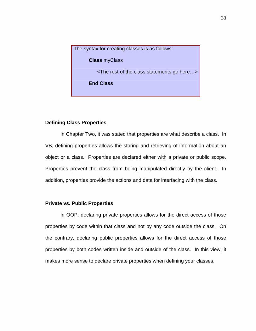
Classes in VB and VBScript Using classes in VB and VBScript are created in similar fashion. In
VBScript, use the ‘class’ keyword along with the ‘end class’. In VB, you do not
use the ‘class’ nor ‘end class’ keyword. VB automatically assigns this when a
new class module is created. In addition, definition of the class in VBScript must
be in the same program as the code using the class. Have a look at illustration
to see the syntax for creating a class in VBScript.
33
The syntax for creating classes is as follows:
Class myClass
<The rest of the class statements go here…>
End Class
Defining Class Properties
In Chapter Two, it was stated that properties are what describe a class. In
VB, defining properties allows the storing and retrieving of information about an
object or a class. Properties are declared either with a private or public scope.
Properties prevent the class from being manipulated directly by the client. In
addition, properties provide the actions and data for interfacing with the class.
Private vs. Public Properties
In OOP, declaring private properties allows for the direct access of those
properties by code within that class and not by any code outside the class. On
the contrary, declaring public properties allows for the direct access of those
properties by both codes written inside and outside of the class. In this view, it
makes more sense to declare private properties when defining your classes.

34
Manipulating Private Properties
VB provides special ways for the programmer to assign and retrieve
values from private properties. It provides three procedures for such use:
‘Property Let’, ‘Property Get’, and ‘Property Set’ procedures.
Declaring Private Properties
When declaring private properties, use the ‘Private’ keyword, instead of
the ‘Dim’ keyword. Private properties are declared similarly to regular variables,
instead the ‘Private’ keyword is used.
Private properties declarations.
Class Student
Private strLastName
Private strFirstName
Private intAge
End Class
Property Let Procedure
‘Property Let’ as the name suggests, gives code from outside the class
permission to access private properties of a class. Outside code is permitted to
assign values to privately declared properties with this procedure. No value is

35
returned to the ‘Property Let’ procedure, since its purpose is to assign values.
Below is an example of the ‘Property Let’ procedure.
Property Let procedure
Class Student
Private strLastName
Private strFirstName
Private intAge
Public Property Let StudentFirstName(FirstName)
strFirstName = FirstName
End Property
End Class
What is going on?
When defining the procedure, use the ‘Property’ statement to inform VB
that a ‘Property’ procedure is being written. The ‘Let’ keyword tells VB that
permission is given to outside code to assign values to the private properties of
the class. The property’s name will be used to access it from the calling code.
Public Property Let StudentFirstName

36
Next, there is a parameter being passed to the ‘Property Let’ procedure.
There must be at least one parameter passed to this procedure and it should be
the value being stored by the property .
Public Property Let StudentFirstName(FirstName)
The value of the parameter is then assigned to the private property
variable that was declared in the class.
strFirstName = FirstName
Lastly, the procedure must end with an ‘End Property’ as we did with a
‘Subroutine’, ‘Function’, and ‘Class’. This tells VB that we are done with this
property and it can proceed with the remainder of the code.
End Property
Property Get Procedure
This procedure is also self-explanatory. It allows the outside code to
retrieve a value stored in a private property. After assigning a value to a property,
use the ‘Property Get’ procedure to give access to outside code to retrieve its

37
value. Unlike the ‘Let’ procedure, that does not return a value, the ‘Get’
procedure returns a value of the property to the calling code.
Property Get’ procedure
Class Student
Private strLastName
Private strFirstName
Private intAge
Public Property Get StudentFirstName()
StudentFirstName = strFirstName
End Property
End Class
What is going on?
The ‘Get’ keyword is used instead of the ‘Let’ keyword to tell VB that we
are giving permission to outside code to retrieve values from our private
properties. The property’s name will be used to access it from the calling code.
There is no need for the passing of a parameter. The ‘Property Get’ procedure
already has access to private properties and does not need them to be passed
as parameters.
Public Property Get StudentFirstName()
38
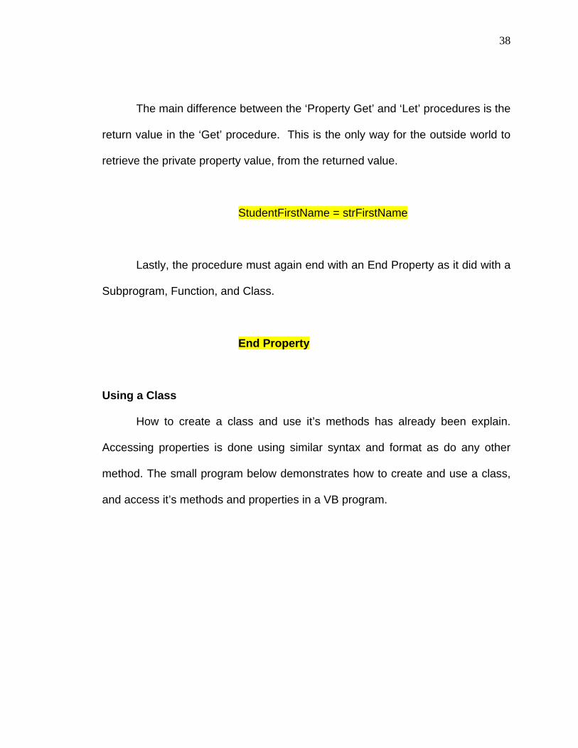
The main difference between the ‘Property Get’ and ‘Let’ procedures is the
return value in the ‘Get’ procedure. This is the only way for the outside world to
retrieve the private property value, from the returned value.
StudentFirstName = strFirstName
Lastly, the procedure must again end with an End Property as it did with a
Subprogram, Function, and Class.
End Property
Using a Class
How to create a class and use it’s methods has already been explain.
Accessing properties is done using similar syntax and format as do any other
method. The small program below demonstrates how to create and use a class,
and access it’s methods and properties in a VB program.

39
Class cStudents
Private strFirstName, strLastName
Private Sub Class_Initialize()
' Initialize variables
strFirstName = “”
strLastName = “”
End Sub
Private Sub Class_Terminate()
' Destroy the objects created in the initialize event
End Sub
Public Property Let StudentFirstName(FirstName)
strFirstName = FirstName
End Property
Private Property Get StudentFirstName()
StudentFirstName = strFirstName
End Property
Public Property Let StudentLastName(LastName)
strLastName = LastName
End Property
Private Property Get StudentLastName()
StudentLastName = strLastName
End Property
End Class %>
<%

40
' This variable will hold an instance of the cStudents class
Dim objStudent
' create the instance of the cBuffer class
Set objStudent = New cStudents
' Set the StudentFirstName property of the cStudents class
objStudent.StudentFirstName = "James"
' Set the StudentLastName property of the cStudents class
objStudent.StudentLastName = "Brown"
' Get the Student First Name of the cStudents class
Response.Write objStudent.StudentFirstName
' Get the Student Last Name of the cStudents class
Response.Write objStudent.StudentLastName
' Set the instance of the class to nothing
Set objStudent = Nothing
%>
.

41
Active Server Pages Foundation
In the previous section of this chapter, we looked at the main
programming languages that are used in the Active Server Pages (ASP)
Environment. ASP is a Microsoft based technology used to create dynamic web
applications similar to the one created in this project. Today, dynamic web
development is being used for the Internet and Intranets by businesses and other
institutions throughout the world.
Working with ASP
To run ASP pages on a computer successfully, there must be a web
server capable of handling them installed on the machine. Microsoft provides
users with their free version of a web server for running ASP pages. They allow
users to run Personal Web Server (PWS) and/or Internet Information Server (IIS)
on any machine running Windows 95 or more recent.
Without the use of PWS or IIS, the web browser would not be able to
display ASP pages. The user would get a dialog box asking them if they want to
save the page to disk. If you do not have IIS or PWS installed, try creating a web
page, name it “test.asp,” and see what happens when you try to access this page
using your Internet Explorer or Netscape Navigator web browser. Here is
the .ASP code for the “test.asp” example. Copy and save the code in notepad.

42
<%@ Language=VBScript %> <HTML> <HEAD> <TITLE>Example 1</TITLE> </HEAD> <BODY bgcolor=Lime aLink=DarkTurquoise> <P> </P> <% Response.Write("Hello, world!") %> </BODY>
</HTML>
If you do not already have PWS or IIS installed on your machine go to
Appendix A and follow the setup directions. After you are finished, you can
return to this section and continue with building your ASP pages.
ASP Page Extensions All web pages created to run as ASP pages must have an extension
of .ASP in order to be executed. The .ASP extension informs the web browser
that it is running an ASP page and a connection should be made to the web

43
server, which is going to process the page before displaying any information to
the client.
How ASP Pages Work
First the user types in the URL for the web site they want to see (for
example, http://www.aspsite.com/index.asp), then the Web Server locates the file
and begins processing any code between <% ... %> tags. Any code
between <% ... %> signifies the code is ASP code and will never reach the web
browser. This code is process completely before any information is displayed in
the browser.
After the web server has finished processing the .ASP page, information is
send back to the browser in a format readable by the browser. This format is
usually of the HTML type. In the ASP environment, programmers are able to
work with both HTML and ASP file types. Recently the use of Extensible Markup
Language (XML) files has become common in ASP environments.
Building ASP Pages
All that is needed to create an ASP page is a text editor. Notepad
is the most common text editor for creating ASP pages. Notepad, like other text
editors, allows you to create and edit your ASP pages. Along with Notepad,
there are other advanced editors, like Microsoft Visual InterDev, and Macromedia
DreamWeaver UltraDev that were built specifically for ASP page creation and

44
editing. The language of use will be VBScript. JavaScript can also be used to
create Active Server Pages. Copy the code below into notepad.
<HTML> <HEAD> <TITLE>Example 1</TITLE> </HEAD> <BODY> </BODY>
</HTML>
The code above is only HTML and no ASP code is used. Add the
following line above the <html> tag (see above).
<% @ Language=VBScript %>
This line tells the ASP code parser that VBScript will be used to write
the .ASP page. If JavaScript were being used, then JavaScript would replace
VBScript. Add the following code between the <body> and </body> tags.

45
<% Response.Write “Hello World!” %>
Save the page as ‘helloworld.asp’ in your wwwroot directory. Open your
browser and type ‘http://127.0.0.1/helloworld.asp’ in the URL box and hit enter.
An empty white page with ‘Hello World’ written on top left is displayed.
Congratulations, you just created your first ASP page. If you view the code (view
-> source (in your browser)), you will see that only the output ‘Hello World!’ is
embedded within the HTML tags and no <%, %>, Response.Write or Language
ASP code is there. This is because ASP is a server side scripting language and
all the code was written and executed on the server. Only the output generated
will be displayed in the browser.
Features of ASP ASP provides many features to the programmer. The main use of ASP is
to create dynamic-database-driven web applications. The programmer no longer
has to know how and what the user wants to see on the page. Programmers can
write code that allows ASP pages to be displayed on request by the users. The
upcoming sections discuss how to use ASP to create dynamic web pages.
The Building Blocks of ASP Programming

46
To allow for the construction of a robust web application, as well as a
programmer friendly environment, ASP programming provides a number of built-
in objects to the programmer. A programmer using a different language or
development environment generally defines the functionality of these ASP
objects. Several built-in objects are available to the programmer using the ASP
environment. Listed below are the built-in objects that we are going to focus on.
Just like in other programming languages, these objects are comprised of
methods, properties, events, and collections.
• Request—to get information from the user
• Response—to send information to the user
• Server—to control the Internet Information Server
• Session—to store information about and change settings for the
user’s current Web-server session
• Application—to share application-level information and control
settings for the lifetime of the application
The Makeup of Objects ASP programmable objects comprise of properties that describe them and
operations to be done on them. We read in the Chapter Two that properties are
what describe an object and operations are what is done with them. In addition,
events invoke these objects. In ASP, built-in objects are no different; they are

47
comprised of Properties, Operations, and Events. Assigning and retrieving
values from objects in ASP is done in the same way described earlier.
Object.Property = somevalue ******** House.Color = “Red”
somevalue = Object.Property ******** Color = House.Color
The Application Object The purpose of the application object is to share common data between
users of a web application. Initialization of the application variables occurs when
the application starts. The appropriate values are assigned as the application is
used. The application invokes one instance of the Application Object, and this is
used throughout the application. Think of a house as an application and the
bathroom as an application variable. Whenever someone visits this house and
uses the bathroom, they use the same bathroom. Guests use the bathroom at
different times but it is the same bathroom.
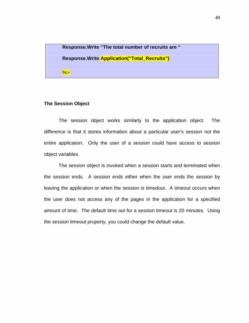
Code snippet of using the Application Object in ASP.
<%
Application (“Total_Recruits”) = 0 Application.Lock
Application (“Total_Recruits”) = Application (“Total_Recruits”) + 1
Application.UnLock
48
Response.Write “The total number of recruits are “ Response.Write Application(“Total_Recruits”)
%>
The Session Object The session object works similarly to the application object. The
difference is that it stores information about a particular user’s session not the
entire application. Only the user of a session could have access to session
object variables.
The session object is invoked when a session starts and terminated when
the session ends. A session ends either when the user ends the session by
leaving the application or when the session is timedout. A timeout occurs when
the user does not access any of the pages in the application for a specified
amount of time. The default time out for a session timeout is 20 minutes. Using
the session timeout property, you could change the default value.
49
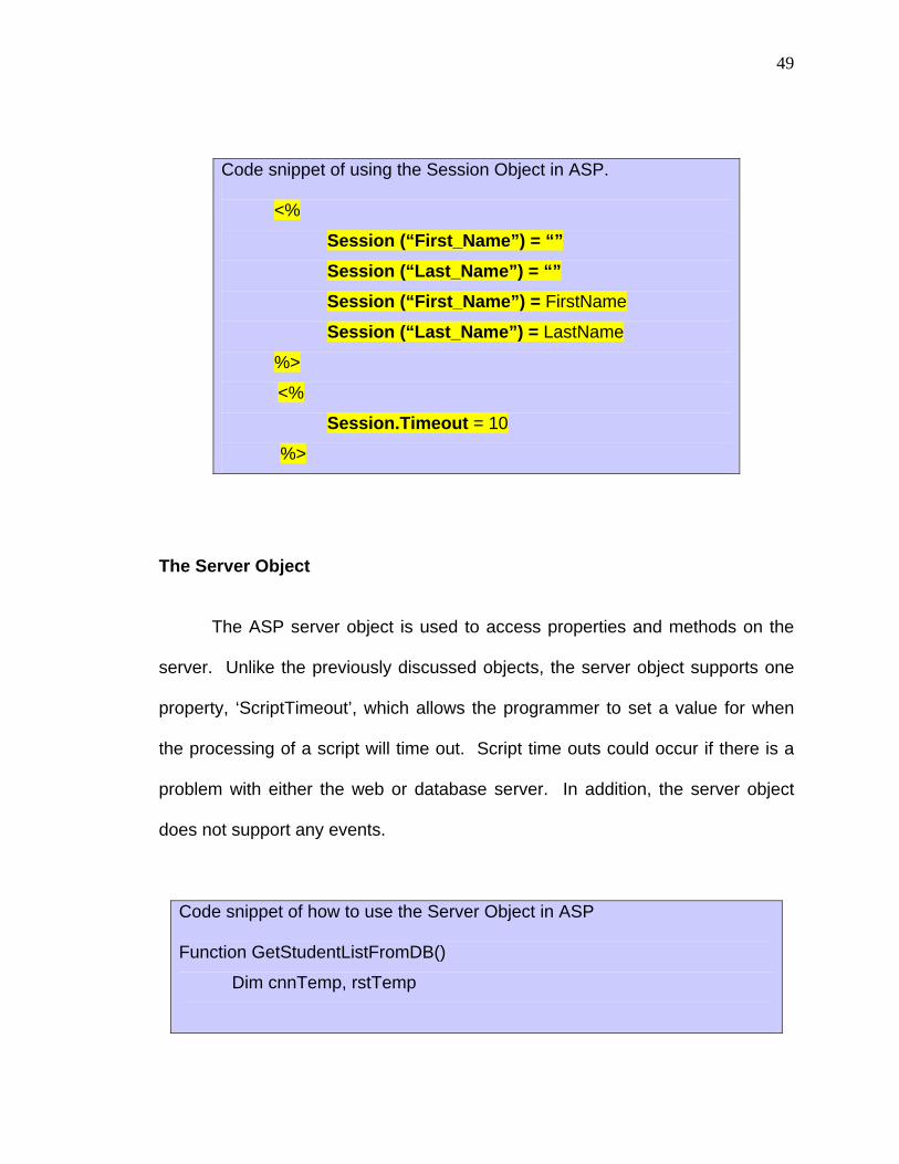
Code snippet of using the Session Object in ASP.
<%
Session (“First_Name”) = “” Session (“Last_Name”) = “” Session (“First_Name”) = FirstName
Session (“Last_Name”) = LastName
%>
<%
Session.Timeout = 10
%>
The Server Object
The ASP server object is used to access properties and methods on the
server. Unlike the previously discussed objects, the server object supports one
property, ‘ScriptTimeout’, which allows the programmer to set a value for when
the processing of a script will time out. Script time outs could occur if there is a
problem with either the web or database server. In addition, the server object
does not support any events.
Code snippet of how to use the Server Object in ASP
Function GetStudentListFromDB()
Dim cnnTemp, rstTemp

50
' Connect to our DB
Set cnnTemp = Server.CreateObject("ADODB.Connection")
cnnTemp.Open "Provider=Microsoft.Jet.OLEDB.4.0; Data Source=" _
& Server.MapPath("College.mdb") & "; User Id=admin; " _
& "Password=;"
‘Create a Record Set
Set rstTemp = Server.CreateObject("ADODB.Recordset")
Set rstTemp.ActiveConnection = cnnTemp
' Get the data from the table
rstTemp.Open "SELECT first, last, email " _
& "FROM tblStudentList ORDER BY last;" _
, , adOpenStatic, adLockReadOnly, adCmdText
' …
' Set the RS as the functions return value
Set GetStudentListFromDB = rstTemp
End Function
The Response Object
The response object is used to forward information to the user. The
response object supports the use collections (to set cookie values). Cookies are
used to store information on the users’ computers for future use e.g. username
and/or password. The response object also supports a number of properties and

51
methods. The methods and properties that are use most often is described
below. The ASP response collections, properties, and methods are described in
Appendix H.
Response.Write
Response.Write syntax <%= %> to print variables in your HTML code
Response.End effectively halts a script in its tracks.
Response.Redirect transfers control to another page
Code snippet showing how to use the Response Object in ASP.
<%
Response.Write "<TABLE Border=1 BorderColor=""BBBBBB"">"
Response.Write " <TR>"
Response.Write " <TD><B>Server Variable Value</B></TD>"
Response.Write " </TR>"
Response.Write "</TABLE>"
%>
The Request Object
The request object works opposite to the response object. Instead of
sending information to the user, it gets information from the user and then
forwards that information in an HTTP request. When a browser asks for a page
from a server, it is called a request.

52
Here is a code snippet of how to use the Request Object. <%
Dim strTo ' Who the message is for
Dim strTakenBy ' Who answered the phone
Dim strCaller ' Who was calling
Dim strSubject ' Out email subject line
Dim strBody ' Our email message body
Dim bMsgSent ' Boolean indication success or failure
' Get the users involved
strTo = Request.Form("to")
strTakenBy = Request.Form("TakenBy")
strCaller = Request.Form("caller")
' Build our subject line
strSubject = "Phone Msg: " & strCaller
' Build our message body
strBody = ""
strBody = strBody & "You got a phone call.” & vbCrLf & vbCrLf
strBody = strBody & " From: " & Request.Form("mrs") & " " &
strBody = strBody & " Of: " & Request.Form("company") &
strBody = strBody & " On: " & Request.Form("date") & vbCrLf
strBody = strBody & " At: " & Request.Form("time") & vbCrLf
strBody = strBody & "Phone: " & Request.Form("phone") & vbCrLf
strBody = strBody & "Notes: " & Request.Form("notes") & vbCrLf
strBody = strBody & vbCrLf & "Message:" & vbCrLf
strBody = strBody & Request.Form("message") & vbCrLf

53
%>