Embed Size (px)
Citation preview

Applying Architecture Tradeoff Assessment Method (ATAM) As Part Of Formal Software Architecture
Review
Christopher Byrnes and Ioannis Kyratzoglou
The MITRE Corporation 202 Burlington Road
Bedford, MA -1730-1420 USA {cb, ioannis}@Mitre.org
Abstract. In preparation for a customer’s Software System Critical Design Review (CDR); we concluded that an assessment approach based on a hybrid version of the Software Engineering Institute’s (SEI) Architecture Trade-Off Analysis Method (ATAM) would be a good approach for an assessment of this software architecture. This paper will provide ideas on how to apply the SEI’s ATAM method within the context of a formal software Critical Design Review (CDR) of a large scale complex software system. .
Keywords: ATAM, software architecture, CMM, SEI, UML, NR-KPP.
1 Background
MITRE and Government support engineers were requested to assess the software architecture for a customer’s project in preparation for a CDR. The focus of this assessment was to investigate at how well system requirements were being designed with particular attention on a number of architecture quality attributes such as, configurability, scalability, modularity, reliability and interoperability. Particular attention was focused on the interoperability and extensibility of the system since it is intended to be enhanced significantly in the future. We concluded that an assessment
2 Christopher Byrnes and Ioannis Kyratzoglou
approach based on a hybrid version of the SEI’s ATAM would be optimum for this assignment based on our experience in applying ATAM to other projects. The time and resources available for the assessment were limited, so our hybrid approach maximized the use of the available assessment resources and software architecture documentation being prepared for this CDR
The Process - ATAM Phases
The ATAM defines four major phases numbered 0 – 3. The activities associated with each phase were tailored to address the CDR needs. The activities are described in greater detail in the subparagraphs below. Briefly, an ATAM (as documented in [1]) Phase 0 consists of an assessment team overview presentation of the proposed software architecture approach and presentation of the initial set of questions. Phase 0 laid the groundwork for the ATAM's Phase 1 and Phase 2, leading to a software architecture assessment report produced during Phase 3.
1.1 Phase 0
During Phase 0, MITRE and Government read the required contract (e.g., Statement of Work), the associated requirement documents and the schedule. The team extracted the related paragraphs that identity the architecture qualities and the types of products that will be presented by the contractor during the CDR. The first item will ensure that we are working within the legal bounds of the contract and the latter will provides us an idea of the products and the architecture presentation style. The next step was to work with the program manager to influence the contents of the CDR material. In parallel, we were preparing the assessment checklists. Using these assessment checklists as our guide, we were able to propose tailored CDR documents and a CDR agenda that will fit the SW Assessment checklist framework.
Typical checklists included a standard ATAM questionnaire; software quality assessment; net-centric checklist for NESI compliance, data management; information assurance, Internet Protocol version 6 (IPv6); DoD Architecture Framework (DoDAF) architecture questionnaire; software best practices; programming models; software framework. The lists served as a backbone for further exploration and questioning. We were also able to get a feel from the users what are the most important mission capabilities and most important architecture quality attributes matched against them.
1.2 Phase 1
Phase 1 covered development of ATAM “business drivers” (which the application domain stakeholders and customer believe are important) and the identification of software architecture approaches. The hybrid approach to ATAM would mean mostly simplifying the software architecture and presentations. We would still go
3
through the same 9 ATAM steps, but with less formality than what is described in the SEI’s ATAM reference. Other ATAM reports that MITRE has participated in during the past have shown the ATAM to be a very "heavyweight" approach; the assessment of this project by necessity of the resource limitations and schedule demands had to be more of a “lightweight” assessment.
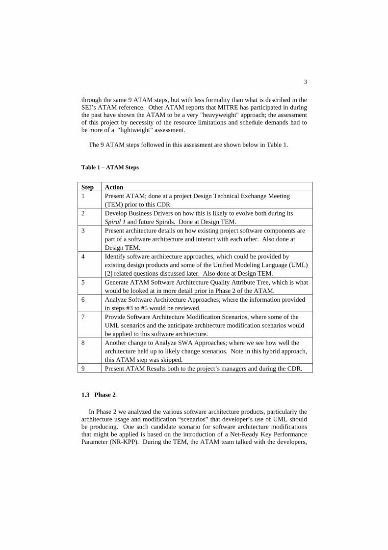
The 9 ATAM steps followed in this assessment are shown below in Table 1.
Table 1 – ATAM Steps
Step Action 1 Present ATAM; done at a project Design Technical Exchange Meeting
(TEM) prior to this CDR. 2 Develop Business Drivers on how this is likely to evolve both during its
Spiral 1 and future Spirals. Done at Design TEM. 3 Present architecture details on how existing project software components are
part of a software architecture and interact with each other. Also done at Design TEM.
4 Identify software architecture approaches, which could be provided by existing design products and some of the Unified Modeling Language (UML) [2] related questions discussed later. Also done at Design TEM.
5 Generate ATAM Software Architecture Quality Attribute Tree, which is what would be looked at in more detail prior in Phase 2 of the ATAM.
6 Analyze Software Architecture Approaches; where the information provided in steps #3 to #5 would be reviewed.
7 Provide Software Architecture Modification Scenarios, where some of the UML scenarios and the anticipate architecture modification scenarios would be applied to this software architecture.
8 Another change to Analyze SWA Approaches; where we see how well the architecture held up to likely change scenarios. Note in this hybrid approach, this ATAM step was skipped.
9 Present ATAM Results both to the project’s managers and during the CDR.
1.3 Phase 2
In Phase 2 we analyzed the various software architecture products, particularly the architecture usage and modification “scenarios” that developer’s use of UML should be producing. One such candidate scenario for software architecture modifications that might be applied is based on the introduction of a Net-Ready Key Performance Parameter (NR-KPP). During the TEM, the ATAM team talked with the developers,
4 Christopher Byrnes and Ioannis Kyratzoglou
system users and other stakeholders about which scenario(s) we would use in this ATAM Phase 2 to assess the robustness of the software architecture.
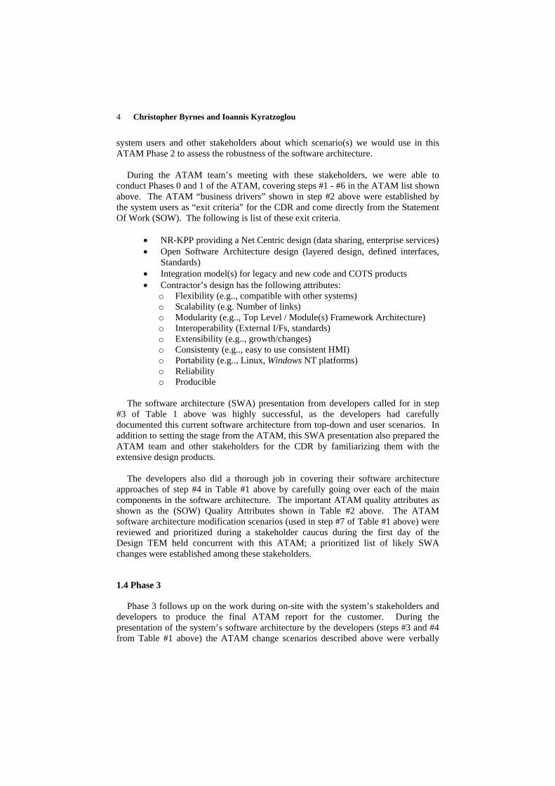
During the ATAM team’s meeting with these stakeholders, we were able to
conduct Phases 0 and 1 of the ATAM, covering steps #1 - #6 in the ATAM list shown above. The ATAM “business drivers” shown in step #2 above were established by the system users as “exit criteria” for the CDR and come directly from the Statement Of Work (SOW). The following is list of these exit criteria.
• NR-KPP providing a Net Centric design (data sharing, enterprise services) • Open Software Architecture design (layered design, defined interfaces,
Standards) • Integration model(s) for legacy and new code and COTS products • Contractor’s design has the following attributes:
o Flexibility (e.g.., compatible with other systems) o Scalability (e.g. Number of links) o Modularity (e.g.., Top Level / Module(s) Framework Architecture) o Interoperability (External I/Fs, standards) o Extensibility (e.g.., growth/changes) o Consistenty (e.g.., easy to use consistent HMI) o Portability (e.g.., Linux, Windows NT platforms) o Reliability o Producible
The software architecture (SWA) presentation from developers called for in step
#3 of Table 1 above was highly successful, as the developers had carefully documented this current software architecture from top-down and user scenarios. In addition to setting the stage from the ATAM, this SWA presentation also prepared the ATAM team and other stakeholders for the CDR by familiarizing them with the extensive design products.
The developers also did a thorough job in covering their software architecture
approaches of step #4 in Table #1 above by carefully going over each of the main components in the software architecture. The important ATAM quality attributes as shown as the (SOW) Quality Attributes shown in Table #2 above. The ATAM software architecture modification scenarios (used in step #7 of Table #1 above) were reviewed and prioritized during a stakeholder caucus during the first day of the Design TEM held concurrent with this ATAM; a prioritized list of likely SWA changes were established among these stakeholders.
1.4 Phase 3
Phase 3 follows up on the work during on-site with the system’s stakeholders and developers to produce the final ATAM report for the customer. During the presentation of the system’s software architecture by the developers (steps #3 and #4 from Table #1 above) the ATAM change scenarios described above were verbally
5
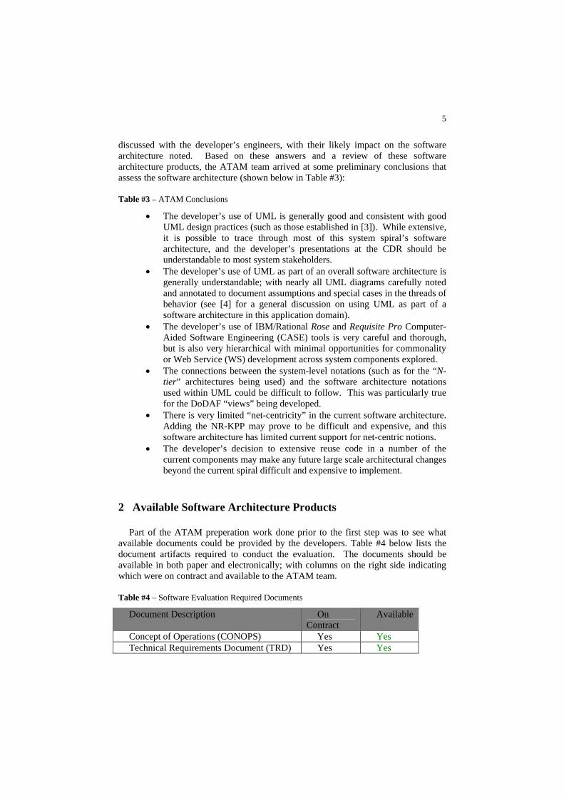
discussed with the developer’s engineers, with their likely impact on the software architecture noted. Based on these answers and a review of these software architecture products, the ATAM team arrived at some preliminary conclusions that assess the software architecture (shown below in Table #3):
Table #3 – ATAM Conclusions
• The developer’s use of UML is generally good and consistent with good UML design practices (such as those established in [3]). While extensive, it is possible to trace through most of this system spiral’s software architecture, and the developer’s presentations at the CDR should be understandable to most system stakeholders. The developer’s use of UML as part of an ov• erall software architecture is generally understandable; with nearly all UML diagrams carefully noted and annotated to document assumptions and special cases in the threads of behavior (see [4] for a general discussion on using UML as part of a software architecture in this application domain). The developer’s use of IBM/Rational Rose and R• equisite Pro Computer-Aided Software Engineering (CASE) tools is very careful and thorough, but is also very hierarchical with minimal opportunities for commonality or Web Service (WS) development across system components explored. The connections between the system-level notations (such as for the “N• -tier” architectures being used) and the software architecture notations used within UML could be difficult to follow. This was particularly true for the DoDAF “views” being developed. There is very limited “net-centricity” in th• e current software architecture. Adding the NR-KPP may prove to be difficult and expensive, and this software architecture has limited current support for net-centric notions. The developer’s decision to extensive reuse code in a number of th• e current components may make any future large scale architectural changes beyond the current spiral difficult and expensive to implement.
2 Available Software Architecture Products
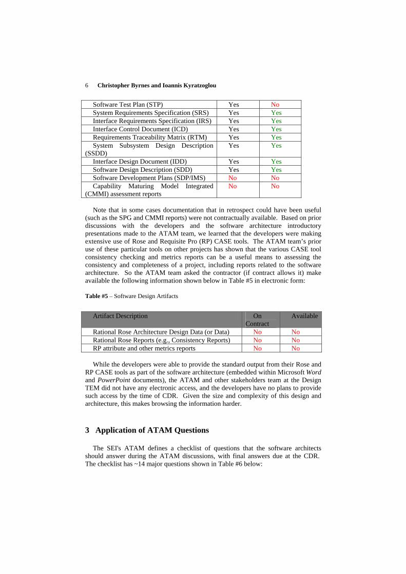
Part of the ATAM preperation work done prior to the first step was to see what available documents could be provided by the developers. Table #4 below lists the document artifacts required to conduct the evaluation. The documents should be available in both paper and electronically; with columns on the right side indicating which were on contract and available to the ATAM team.
Table #4 – Software Evaluation Required Documents
Document Description On Contract
Available
Concept of Operations (CONOPS) Yes Yes Technical Requirements Document (TRD) Yes Yes
6 Christopher Byrnes and Ioannis Kyratzoglou
Software Test Plan (STP) Yes No System Requirements Specification (SRS) Yes Yes Interface Requirements Specification (IRS) Yes Yes Interface Control Document (ICD) Yes Yes Requirements Traceability Matrix (RTM) Yes Yes System Subsystem Design Description
(SSDD) Yes Yes
Interface Design Document (IDD) Yes Yes Software Design Description (SDD) Yes Yes Software Development Plans (SDP/IMS) No No Capability Maturing Model Integrated
(CMMI) assessment reports No No
Note that in some cases documentation that in retrospect could have been useful
(su
Table #5 – Software Design Artifacts
ch as the SPG and CMMI reports) were not contractually available. Based on prior discussions with the developers and the software architecture introductory presentations made to the ATAM team, we learned that the developers were making extensive use of Rose and Requisite Pro (RP) CASE tools. The ATAM team’s prior use of these particular tools on other projects has shown that the various CASE tool consistency checking and metrics reports can be a useful means to assessing the consistency and completeness of a project, including reports related to the software architecture. So the ATAM team asked the contractor (if contract allows it) make available the following information shown below in Table #5 in electronic form:
Artifact Description On
Co t ntracAvailable
Rational Rose Architecture Design Data (or Data) No No Rational Rose Reports (e.g., Consistency Reports) No No RP attribute and other metrics reports No No While the developers were able to provide the standard output from their Rose and
RP
3 Application of ATAM Questions
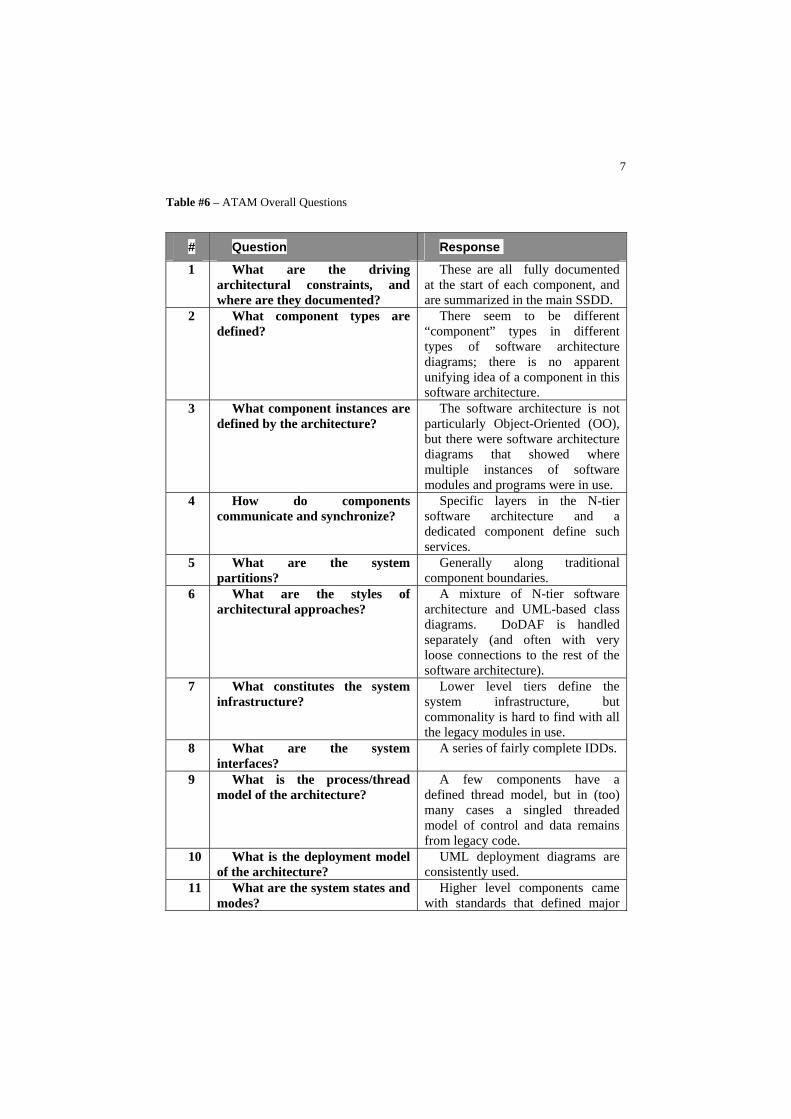
The SEI's ATAM defines a checklist of questions that the software architects should answer during the ATAM discussions, with final answers due at the CDR. The checklist has ~14 major questions shown in Table #6 below:
CASE tools as part of the software architecture (embedded within Microsoft Word and PowerPoint documents), the ATAM and other stakeholders team at the Design TEM did not have any electronic access, and the developers have no plans to provide such access by the time of CDR. Given the size and complexity of this design and architecture, this makes browsing the information harder.
7
Table #6 – ATAM Overall Questions
# Question Response
1 What are the driving architectural constraints, and
These are all fully documented at the start of eac
where are they documented? h component, and
are summarized in the main SSDD. 2 What component types are
defined? There seem to be different
“component” types in different types of s ftware architecture dia e is no apparent
ograms; ther
unifying idea of a component in this software architecture.
3 are de
pa
What component instancesfined by the architecture?
The software architecture is notrticularly Object-Oriented (OO),
but there were software architecture diagrams that showed where multiple instances of software modules and programs were in use.
4 How do components co
the N-tier sommunicate and synchronize?
Specific layers inftware architecture and a
dedicated component define such services.
5 What are the system partitions?
Generally along traditional component boundaries.
6 What are the styles of ar
nections to the rest of the
chitectural approaches? arcA mixture of N-tier softwarehitecture and UML-based class
diagrams. DoDAF is handled separately (and often with very loose consoftware architecture).
7 nstitutes the system in
define the y
What cofrastructure? s
Lower level tiers stem infrastructure, but
commonality is hard to find with all the legacy modules in use.
8 What are the system interfaces?
A series of fairly complete IDDs.
9 What is the process/thread m
ts have a deodel of the architecture?
A few componenfined thread model, but in (too)
many cases a singled threaded model of control and data remains from legacy code.
10 ecture? consistently used.
What is the deployment model of the archit
UML deployment diagrams are
11 What are the system states and modes?
Higher level components came with standards that defined major
8 Christopher Byrnes and Ioannis Kyratzoglou
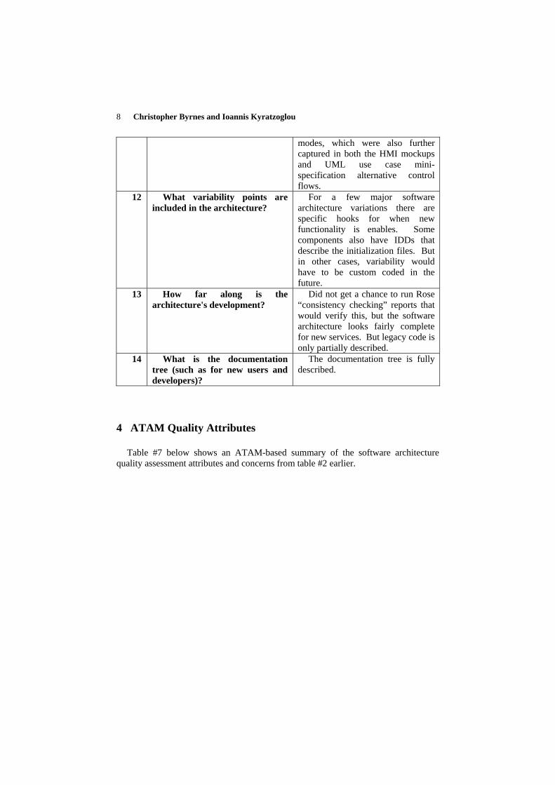
modes, which were also further captured in both the HMI mockups and UML use case mini-specification alternative control flows.
12 What variability points are included in the architecture?
r cases, variability would ha
For a few major software architecture variations there are specific hooks for when new functionality is enables. Some components also have IDDs that describe the initialization files. But in othe
ve to be custom coded in the future.
13 How far along is the architecture's development?
Did not get a chance to run Rose “consistency checking” reports that would verify this, but the software architecture looks fairly complete for new services. But legacy code is only partially described.
14 What is the documentation tre
documentation tree is fully ee (such as for new users and
developers)? d
The scribed.
4 ATAM Quality Attributes
Table oftware architecture qu ty as utes and concerns from table #2 earlier.
#7 below shows an ATAM-based summsessment attrib
ary of the sali
9
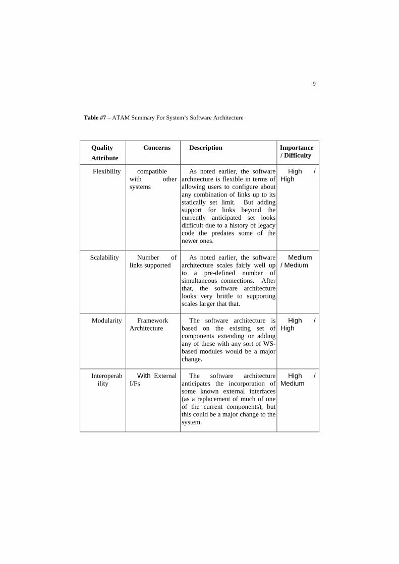
Table #7 – ATAM Summary For System’s Software Architecture
Quality Attribute
Concerns Description Importance / Difficulty
Flexibility compatible with other systems
As noted earlier, the software architecture is flexible in terms of allowing users to configure about any combination of links up to its statically set limit. But adding support for links beyond the currently anticipated set looks difficult due to a history of legacy code the predates some of the newer ones.
High / High
Scalability Number of links supported arc
As noted earlier, the software hitecture scales fairly well up
to a pre-defined number of simultaneous connections. After that, the software architecturelooks very brittle to supporting scales larger that that.
Medium / Medium
Modularity Framework Architecture
The software architecture is based on the existing set of components extending or adding any of these with any sort of WS-based modules would be a major change.
HHigh /
igh
Interoperability
With External I/Fs
The software architectureanticipates the incorporation of some known external interfaces(as a replacement of much of one of the current components), but this could be a major change to the system.
High / Medium
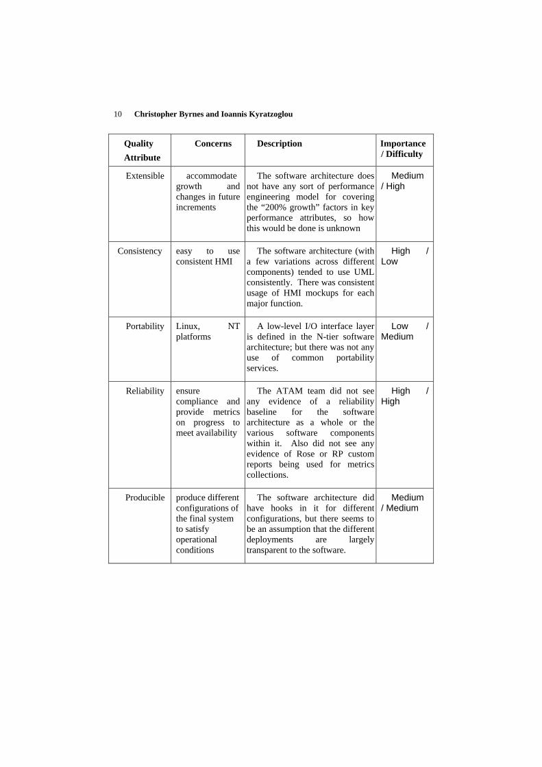
10 Christopher Byrnes and Ioannis Kyratzoglou
Quality Attribute
Concerns Description Importance / Difficulty
Extensible accommodate growth and changes in future increments
The software architecture does not have any sort of performance engineering model for covering the “200% growth” factors in key performance attributes, so how this would be done is unknown
Medium / High
Consistency easy to use consistent HMI
The software architecture (with a few variations across different components) tended to use UML consistently. There was consistent usage of HMI mockups for each major function.
High / Low
Portability Linux, NT platforms
A low-level I/O interface layer is defined in the N-tier software architecture; but there was not any use of common portability services.
Low / Medium
Reliability ensure compliance and provide metrics on progress to meet availability
The ATAM team did not see any evidence of a reliability baseline for the software architecture as a whole or the various software components within it. Also did not see any evidence of Rose or RP custom reports being used for metrics collections.
High / High
Producible produce different configurations of the final system to satisfy operational conditions
The software architecture did have hooks in it for different configurations, but there seems to be an assumption that the different deployments are largely transparent to the software.
Medium / Medium
11
5 Risks in System’s Software Architecture
This is a summary of the major risks identified by the use of ATAM in this system’s software architecture:
• The developer’s use of RP CASE tools is very careful and thorough, but is
also very hierarchical with minimal opportunities for commonality or WS development across components explored. The connections between the system-level not• ations (such as for the “N-tier” architectures being used) and the software architecture notations used within UML could be difficult to follow. It was difficult to see these N-tiers elsewhere in the software architecture, such as in the DoDAF views or the UML use cases There is very limited “net-ce• ntricity” in the current software architecture. Adding the NR-KPP may prove to be difficult and expensive, and this software architecture has limited current support for net-centric notions. The developer’s decision to extensive reuse code in a number of th• e current components may make any future large scale architectural changes beyond the current spiral difficult and expensive to implement. Being spread out over so many files made the software archit• ecture and specific portions within it (such as the RTM) hard to browse and search. Lack of anything resembling any UML “activity” or “collaboration• ” diagram in these SSDDs tended to reinforce the hierarchical description of the use cases and made more abstract behaviors (that spanned multiple use case alternatives) harder to see. Too many assumptions about single • threaded components and services.
• The data layouts of some of the packets being exchanged could be hard to follow in some of the (legacy) tabular formats used.
6 Conclusions
We found the ATAM a useful method for assessing a software architecture against known quality criteria established by the contract and the stakeholders. By fitting a hybrid version of the ATAM into existing deliverable products and meeting schedules, we were ably to apply this method with minimal changes to ongoing development and presentation plans. The same detailed familiarization approaches called for by the ATAM were also useful as a general preparation step for the CDR, as it allowed stakeholders to focus on areas of greatest interest to them. There were a number of both documentation and process improvements that this system (or other systems) could make in the future to allow software architecture products to be made more readily available for similar types of assessments.
12 Christopher Byrnes and Ioannis Kyratzoglou
References
1. Clements, C., Kazman, R., Klein, M.: Evaluating Software Architectures. Addison-Wesley, Boston (2002)
2. Object Management Group (OMG): Unified Modeling language (UML) v1.5 Specification (2003)
3. Quatrani, T.: Visual Modeling With Rational Rose and UML. Addison-Wesley, Boston (2002)
4. Byrnes, C.: Requirements and Design Approach for a High-Reliability System. In: Firesmith, D. (ed.) Proceedings of Fifth International Workshop on Requirements for High Assurance Systems (RHAS 05), IEEE, New York, 2005

13