Embed Size (px)
Citation preview

Copyright © SEL 2016
Apply Travelling Wave in Power System Protection and Operation
Edmund O. Schweitzer, III Bogdan Kasztenny Armando Guzmán Veselin Skendzic Venkat Mynam
Schweitzer Engineering Laboratories, Inc.

• Traditional models are steady-state • The “forcing functions” are at 60 Hz • Instrument transformers are rated at 60 Hz • CCVTs are “band-pass” devices at 60 Hz
Phasor-Based Protection Makes Sense
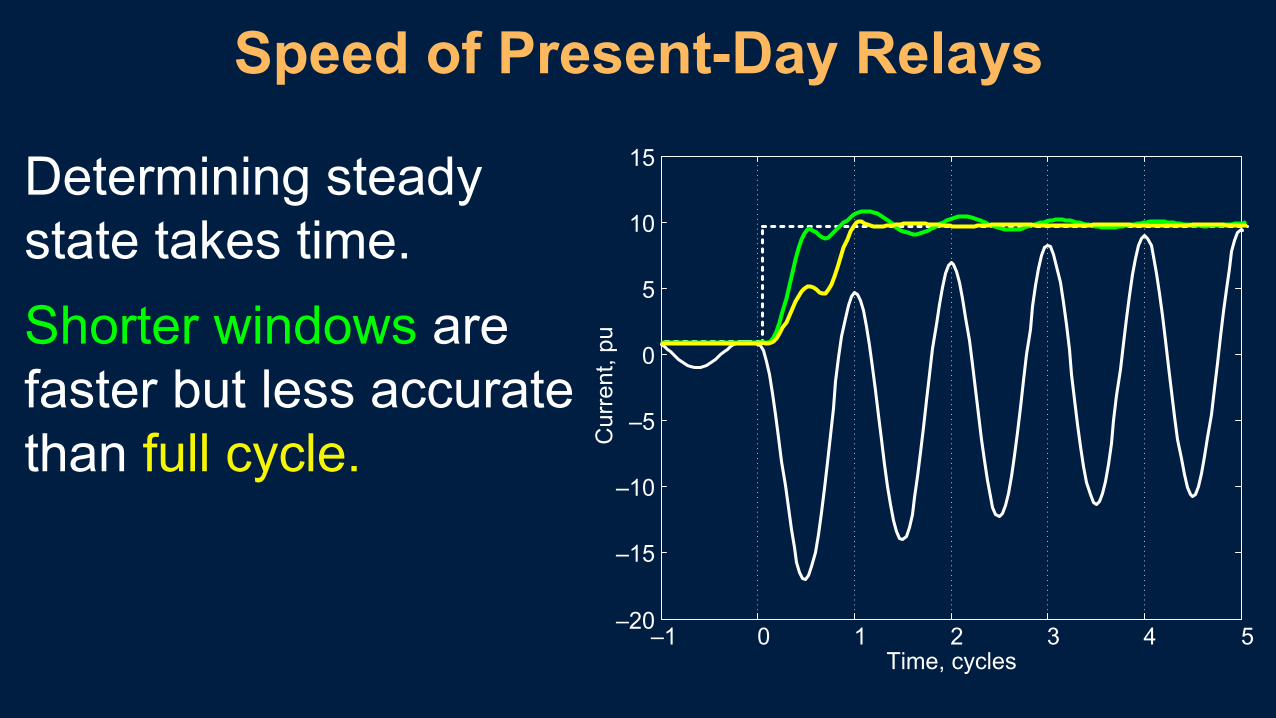
Determining steady state takes time. Shorter windows are faster but less accurate than full cycle.
Speed of Present-Day Relays
–1 0 1 2 3 4 5–20
–15
–10
–5
0
5
10
15
Time, cycles
Cur
rent
, pu

Ope
ratin
g Ti
me
in C
ycle
s
Fault Location in Percent of Set Reach
Line-to-ground fault, SIR = 1.0
Modern Distance Relays: 8–16 ms
0 10 20 30 40 50 60 70 80 90 0
0.5
1
1.5
100

• Increase power system stability • Allow more power transfer • Enhance public and utility personnel safety • Limit equipment wear • Improve power quality • Reduce property damage
Quest for Ultra-Fast Relay Operation

15 MW more per millisecond saved R. B. Eastvedt, BPA, 1976 WPRC
The Need for Speed Moving Energy at the Speed of Light
Safer • Less Damage • Improved Dynamics

ASEA RALDA (1976) 5 ms Directional Wave Relay
−
B
Di Dv Di Dv− + −
+ + − +
A

BBC LR-91 (1985) 5 ms UHS Directional Relay
Fault is forward when the operating point enters the 2nd or 4th quadrant

Why Today? The Need for Speed
Faster communications Powerful processors Better simulations
May be simpler

Waves Travel Toward Line Terminals
vRvSiRiS F

Practical Traveling Wave Relaying Build on TWFL Experience
Single-ended: sort out reflections; easier with voltages Two-ended:
Directional comparison Current differential

Speed of Light Limits Relay Time
The fastest communications path is the line
S R100-mile line ≈ 600 µs X
300 µs 300 µs
600 µs by line or 1,000 µs by fiber
900 µs or 1,300 µs
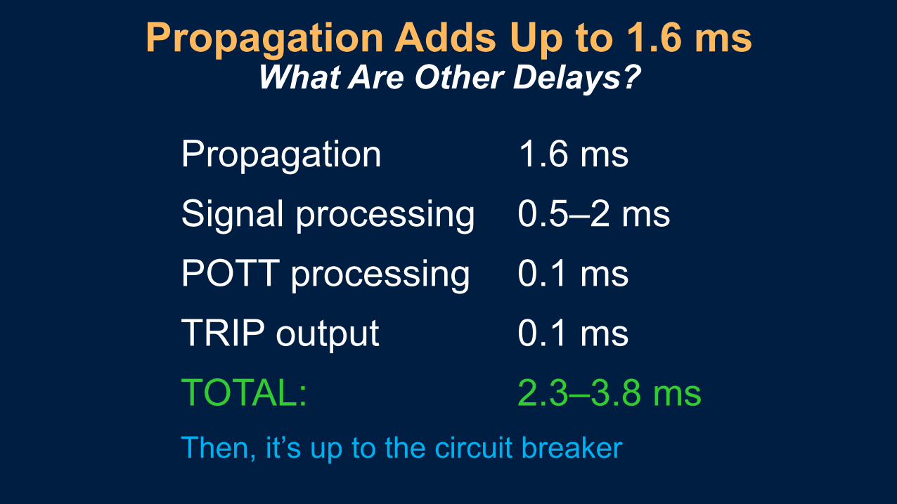
Propagation Adds Up to 1.6 ms What Are Other Delays?
Propagation 1.6 ms Signal processing 0.5–2 ms POTT processing 0.1 ms TRIP output 0.1 ms TOTAL: 2.3–3.8 ms Then, it’s up to the circuit breaker

Speed Limiters and Options
Circuit breaker 17 ms Solid state? Auxiliary relay 4 ms Don’t use
Contact input delay 1 ms Improve signaling Process bus 1.5 ms Hard wire
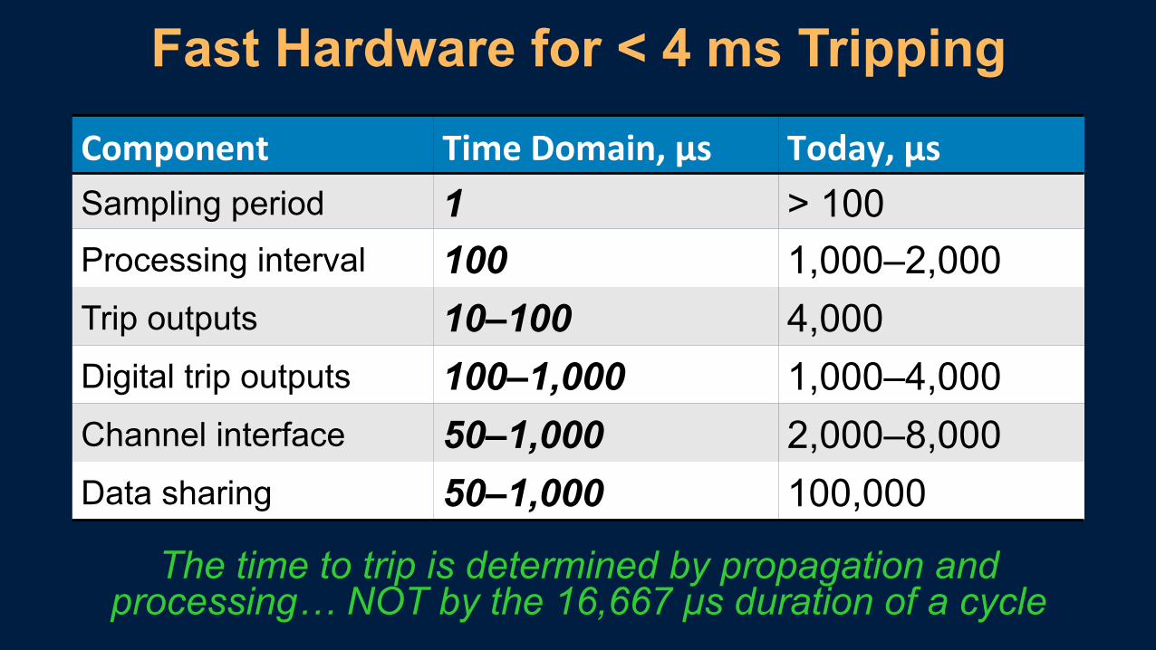
Fast Hardware for < 4 ms Tripping
The time to trip is determined by propagation and processing… NOT by the 16,667 µs duration of a cycle
Component TimeDomain,μs Today,μs Sampling period 1 > 100 Processing interval 100 1,000–2,000 Trip outputs 10–100 4,000 Digital trip outputs 100–1,000 1,000–4,000 Channel interface 50–1,000 2,000–8,000 Data sharing 50–1,000 100,000

TD21 § Underreaching (Zone 1) § Communications-independent
POTT § TD32 and TW32 for direction § Fast MIRRORED BITS® communications as a teleprotection channel
TW87 § Current-only § Direct fiber as a channel (100 Mbps) § GPS-independent
Modern TW Relay: Speed With Security
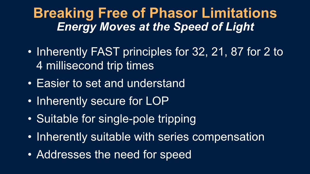
• Inherently FAST principles for 32, 21, 87 for 2 to 4 millisecond trip times
• Easier to set and understand • Inherently secure for LOP • Suitable for single-pole tripping • Inherently suitable with series compensation • Addresses the need for speed
Breaking Free of Phasor Limitations Energy Moves at the Speed of Light