Embed Size (px)
Citation preview
Applications of Image Analysis in Fractography of Fatigue Failures H. Lauschmann and I. Nedbal Czech Technical University, Faculty of Nuclear Sciences & Physical Engineering, Dept. of Materials, Trojanova 13, 12000 Praha 2, Czech Republic, [email protected] ABSTRACT. New methods of image processing and analysis have found application in fractography of fatigue failures: 1. Recognition and evaluation of striation patches. A new definition of striation patch is proposed. Two methods of automatic striation analysis are explained. 2. Within textural fractography, images of fracture surfaces are studied as image textures - "regularly random" image structures. The mezoscopic dimensi-onal area with SEM magnifications between macro- and microfractography (about 30 to 500 x) is especially suitable. Fractographic information is extracted as integral parameters of whole images. Several methods of characterizing fractographic image textures have been developed: image transforms – Fourier and auto-shape, modeling the texture as a Gibbs random field, and extraction and analysis of fibre-similar bright objects. Image para-meters are related to the crack growth rate (CGR) by means of multilinear regression. Results of application on laboratory fatigue tests of stainless steel AISI 304L are shown. INTRODUCTION Fractography is an irreplaceable source of information on causes and mechanisms of fractures in practice. The basic task of the quantitative fractography of fatigue failures is the fractographic reconstitution of the history of a fatigue crack, i.e., estimation of the dependence of the crack development (usually in the form of crack length a or of the cracked area) on the number N of loading cycles or blocks in the case of laboratory loading, or on the operational time of the structure. The main step [1] is estimation the course v(a) of the crack growth rate (CGR) along crack length a. Then crack growth process a(N) can be reconstituted by integration ∆N = ∫ da/v(a).
Fig. 1 A schematic plot of the dependence of ( ) /D s v s= on mean striation spacing s .
∼ 0.1 ∼ 1
∼ 1
D [1]
s [µm]
The traditional quantitative fractography is based on measuring fractographic features, i.e., exactly defined geometrical objects in the image. These single objects are identified and required characteristics are measured at each of them. In the case of fatigue, striation patches and/or beach lines are the most typical features, and striation spacing is the most valuable characteristic. Fig.1 shows the general character of material function D [1] , expressing the ratio between macroscopic CGR and striation spacing s . From a known s , CGR can be estimated as ( )v s D s= .
The progress of computers and image analysis methods inspired the development of the computer aided fractography. In addition to a more effective mode of the fracto-graphic routine, it opens up qualitatively new possibilities of the fractographic analysis.
Within the traditional fractography, image analysis methods can be used to recognize striations in images of crack surfaces, and to estimate their parameters. A new definition of a striation patch linked closely to Fourier transformation was proposed. Two methods of estimating striation parameters were developed.
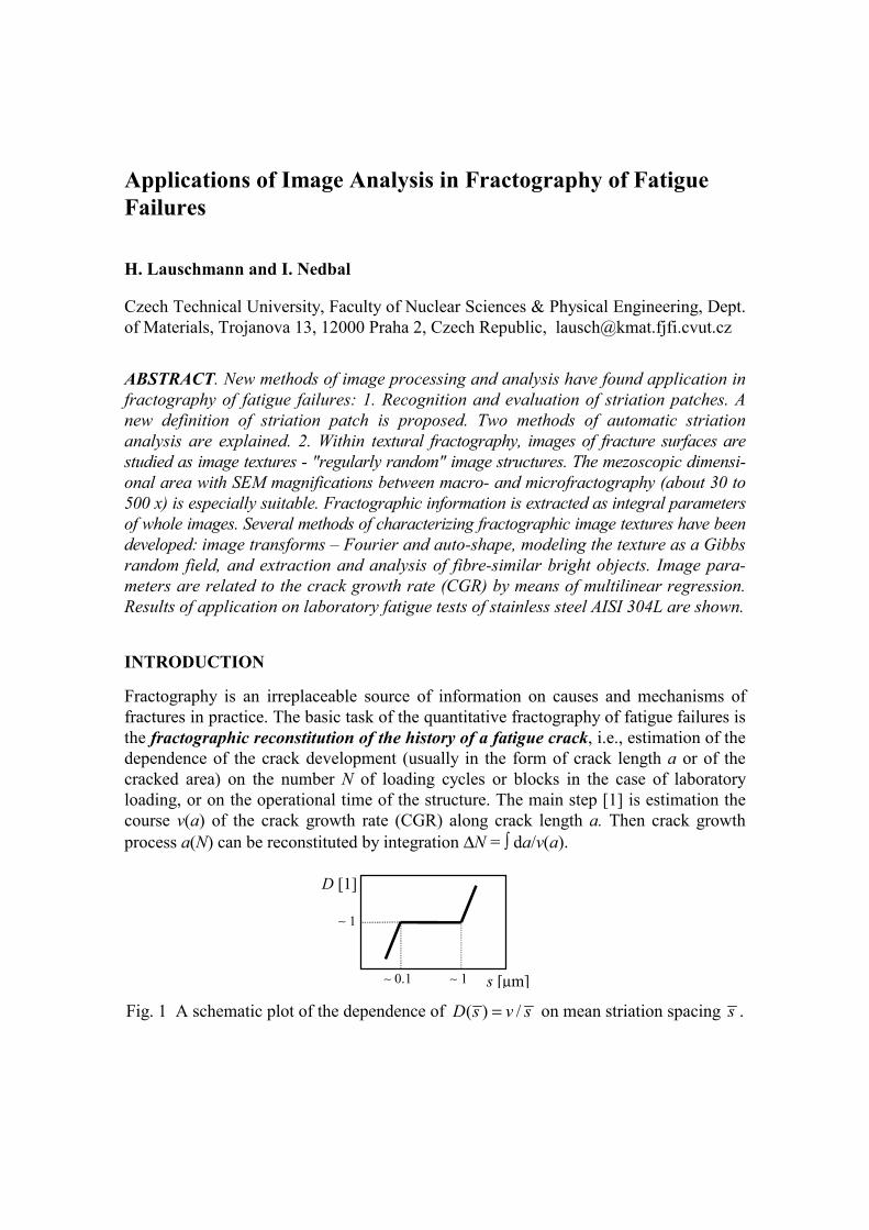
Especially for the cases when striations do not exist or are not visible in the fracture surface, a new method was developed – textural fractography. In comparison to the traditional fractography, a fundamental change is in the information source: instead of a discrete fractographic feature, the elementary information unit is a part of the fracture surface as a whole. ANALYSIS OF STRIATION PATCHES The New Definition of an Ideal Striation Patch Traditionally, a striation patch is understood intuitively as a system of parallel strips. Striation vector s (spacing and direction) is measured along a perpendicular direction, which, in fact, is often more or less arbitrary (Fig.2a). If the plane of projection is not parallel to the plane of a striation patch (or to the axis of a cylindrical striation patch), the angle relations are distorted, and the normal to striations in the image is different from the projection of the normal to striations in real space (Fig.2b). To understand the striation parameters unambiguously, let us define an ideal striation patch as a system of
TRADITIONAL NEW
a b c d
Fig. 2 Traditional and new concept of a striation patch: a - the normal to arc striations is ambiguous, b - perpendicularity is distorted by projection, c - vector of shifting is unique in the whole patch, d - direction of shifting is invariant to projection.
s2 s1 s3 s
s
s s
s'
similar space arcs shifted equidistantly in the same direction [2]. Then vector of the shifting is the same in the whole patch (Fig.2c), and can be used to define the striation vector. Its projection is just the vector of the shifting of projected arcs (Fig.2d). Due to this, when following the above definition we are less subjective and closer to the reality. Of course, real striation patches are not ideal. Assuming a model of the ideal striation patch, we estimate parameters of the idealization of the given striation patch towards the model.
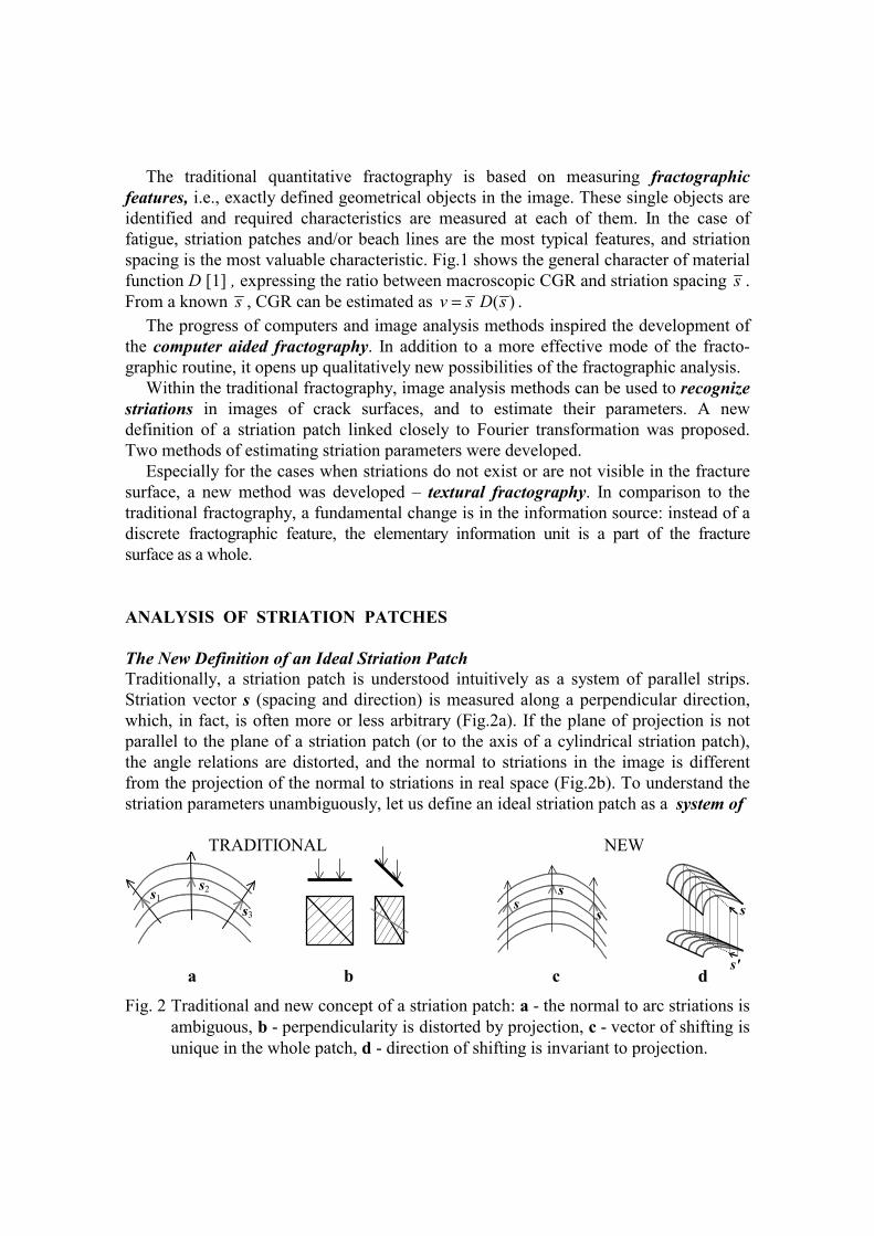
Fig. 3 Example of a system of shifted arcs (a), its Fourier spectrum (b) and a system of straight lines with the same vector of shifting (c).
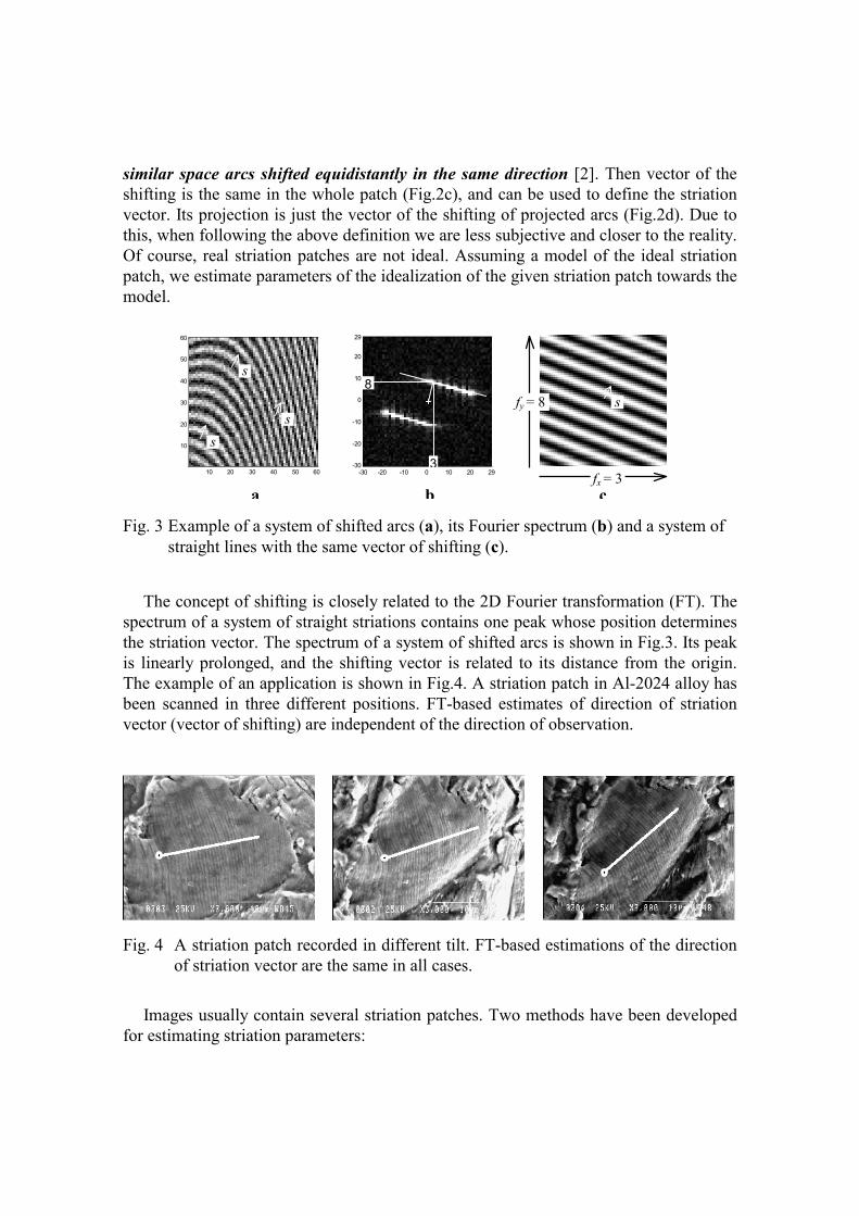
The concept of shifting is closely related to the 2D Fourier transformation (FT). The spectrum of a system of straight striations contains one peak whose position determines the striation vector. The spectrum of a system of shifted arcs is shown in Fig.3. Its peak is linearly prolonged, and the shifting vector is related to its distance from the origin. The example of an application is shown in Fig.4. A striation patch in Al-2024 alloy has been scanned in three different positions. FT-based estimates of direction of striation vector (vector of shifting) are independent of the direction of observation.
Fig. 4 A striation patch recorded in different tilt. FT-based estimations of the direction of striation vector are the same in all cases.
Images usually contain several striation patches. Two methods have been developed
for estimating striation parameters:
10 20 30 40 50 60
60
50
40
30
20
10
-30 -20 -10 0 10 20 29
29
20
10
0
-10
-20
-30
3
8 fy = 8
fx = 3
s
s
s s
a b c
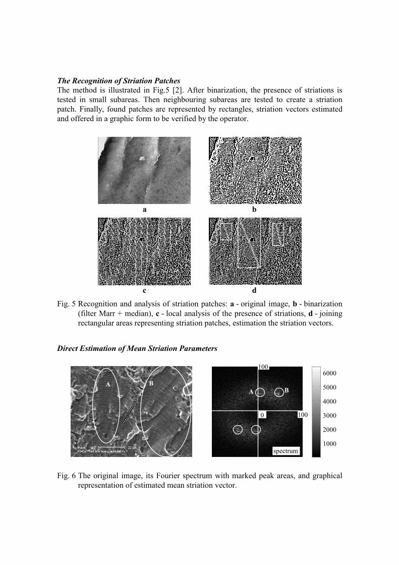
The Recognition of Striation Patches The method is illustrated in Fig.5 [2]. After binarization, the presence of striations is tested in small subareas. Then neighbouring subareas are tested to create a striation patch. Finally, found patches are represented by rectangles, striation vectors estimated and offered in a graphic form to be verified by the operator.
a b
c d
Fig. 5 Recognition and analysis of striation patches: a - original image, b - binarization (filter Marr + median), c - local analysis of the presence of striations, d - joining rectangular areas representing striation patches, estimation the striation vectors.
Direct Estimation of Mean Striation Parameters
1000
2000
3000
4000
5000
6000
Fig. 6 The original image, its Fourier spectrum with marked peak areas, and graphical
representation of estimated mean striation vector.
A B
100
100 0
spectrum
A B
6000
5000
4000
3000
2000
1000
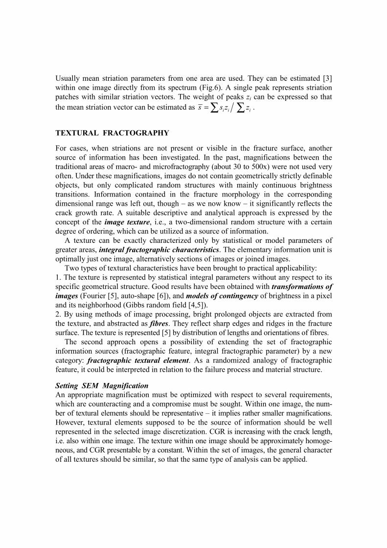
Usually mean striation parameters from one area are used. They can be estimated [3] within one image directly from its spectrum (Fig.6). A single peak represents striation patches with similar striation vectors. The weight of peaks zi can be expressed so that the mean striation vector can be estimated as i i is s z z= ∑ ∑ . TEXTURAL FRACTOGRAPHY For cases, when striations are not present or visible in the fracture surface, another source of information has been investigated. In the past, magnifications between the traditional areas of macro- and microfractography (about 30 to 500x) were not used very often. Under these magnifications, images do not contain geometrically strictly definable objects, but only complicated random structures with mainly continuous brightness transitions. Information contained in the fracture morphology in the corresponding dimensional range was left out, though – as we now know – it significantly reflects the crack growth rate. A suitable descriptive and analytical approach is expressed by the concept of the image texture, i.e., a two-dimensional random structure with a certain degree of ordering, which can be utilized as a source of information.
A texture can be exactly characterized only by statistical or model parameters of greater areas, integral fractographic characteristics. The elementary information unit is optimally just one image, alternatively sections of images or joined images.
Two types of textural characteristics have been brought to practical applicability: 1. The texture is represented by statistical integral parameters without any respect to its specific geometrical structure. Good results have been obtained with transformations of images (Fourier [5], auto-shape [6]), and models of contingency of brightness in a pixel and its neighborhood (Gibbs random field [4,5]). 2. By using methods of image processing, bright prolonged objects are extracted from the texture, and abstracted as fibres. They reflect sharp edges and ridges in the fracture surface. The texture is represented [5] by distribution of lengths and orientations of fibres.
The second approach opens a possibility of extending the set of fractographic information sources (fractographic feature, integral fractographic parameter) by a new category: fractographic textural element. As a randomized analogy of fractographic feature, it could be interpreted in relation to the failure process and material structure.
Setting SEM Magnification An appropriate magnification must be optimized with respect to several requirements, which are counteracting and a compromise must be sought. Within one image, the num-ber of textural elements should be representative – it implies rather smaller magnifications. However, textural elements supposed to be the source of information should be well represented in the selected image discretization. CGR is increasing with the crack length, i.e. also within one image. The texture within one image should be approximately homoge-neous, and CGR presentable by a constant. Within the set of images, the general character of all textures should be similar, so that the same type of analysis can be applied.
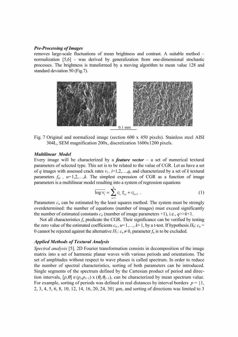
Pre-Processing of Images removes large-scale fluctuations of mean brightness and contrast. A suitable method – normalization [5,6] - was derived by generalization from one-dimensional stochastic processes. The brightness is transformed by a moving algorithm to mean value 128 and standard deviation 50 (Fig.7).
Fig. 7 Original and normalized image (section 600 x 450 pixels). Stainless steel AISI
304L, SEM magnification 200x, discretization 1600x1200 pixels. Multilinear Model Every image will be characterized by a feature vector – a set of numerical textural parameters of selected type. This set is to be related to the value of CGR. Let us have a set of q images with assessed crack rates vi , i=1,2,…,q, and characterized by a set of k textural parameters fui , u=1,2,…,k. The simplest expression of CGR as a function of image parameters is a multilinear model resulting into a system of regression equations
logv c f ci u uiu
k
k= +=
+∑1
1 . (1)
Parameters cu can be estimated by the least squares method. The system must be strongly overdetermined: the number of equations (number of images) must exceed significantly the number of estimated constants cu (number of image parameters +1), i.e., q>>k+1.
Not all characteristics fu predicate the CGR. Their significance can be verified by testing the zero value of the estimated coefficients cu , u=1,…, k+1, by a t-test. If hypothesis H0: cu = 0 cannot be rejected against the alternative H1: cu ≠ 0, parameter fu is to be excluded.
Applied Methods of Textural Analysis Spectral analysis [5]. 2D Fourier transformation consists in decomposition of the image matrix into a set of harmonic planar waves with various periods and orientations. The set of amplitudes without respect to wave phases is called spectrum. In order to reduce the number of spectral characteristics, sorting of both parameters can be introduced. Single segments of the spectrum defined by the Cartesian product of period and direc-tion intervals, [p,θ] ∈(pi,pi+1) x (θj,θj+1), can be characterized by mean spectrum value. For example, sorting of periods was defined in real distances by interval borders p = {1, 2, 3, 4, 5, 6, 8, 10, 12, 14, 16, 20, 24, 30} µm, and sorting of directions was limited to 3
0.1 mm
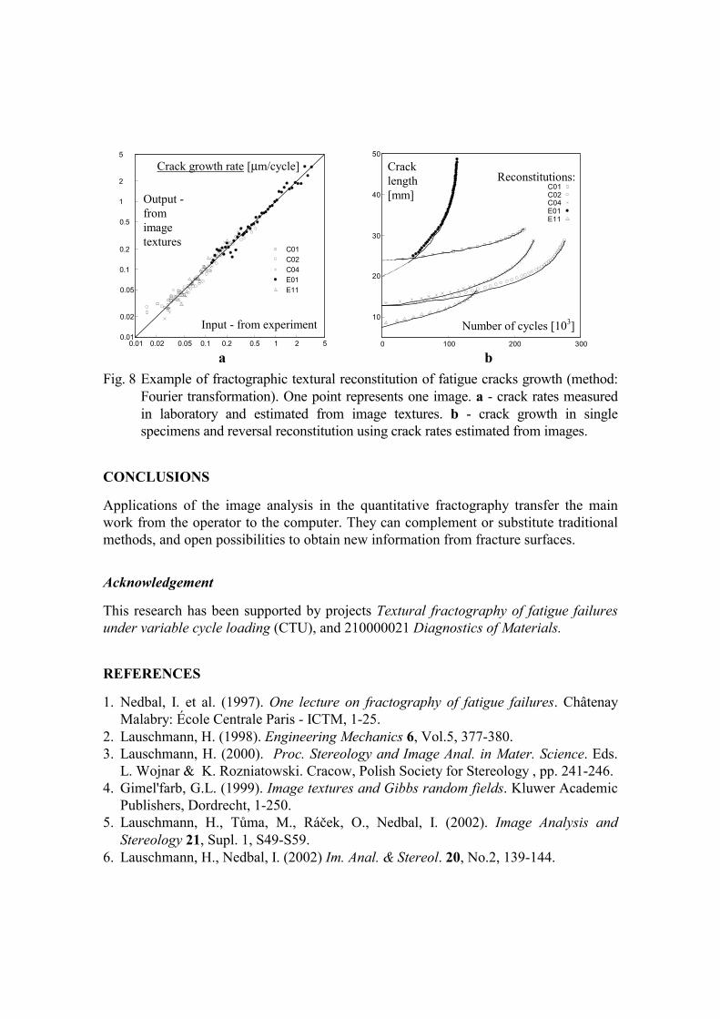
classes: directions close to that of the crack growth, directions close to that of the crack front, and all other directions. All combinations resulted in 45 image parameters. Gibbs random field [4,5]. A simple GRF model of a texture is based on the pair interaction. The description of images is converted from [row index = r, column index = c, gray level = g] to [distance in row = r1-r2 = i, distance in column = c1-c2 = j, difference of gray levels = g1-g2 = d]. All pixel pairs with the same distance vector [i,j] create a clique. The main characteristics of an image are histogram h and potential V. hi,j,d is the number of interactions d in the clique [i, j], Vi,j,d expresses the significance of interaction d in clique [i,j]. Probability measures are derived in a way similar to statistical physics. Estimation of potential V requires applying computationally demanding stochas-tic relaxation. Relative energies ei,j, expressing significance of cliques [i, j], can be taken for image parameters. Only those for small distance components i,j are significant. Analysis of light fibres [5]. In many cases, the most remarkable elements of textures are light prolonged elements with a different thickness and shape. They reflect sharp ridges and edges in the fracture surface, and can be abstracted as a fibre structure. New methods for enhancing, detecting and description of this structure were proposed. The requirement to analyze continuity of fibres in points of crossing or branching led to a database approach. From a parametric regression of fibres, many useful characteristics may be estimated, e.g. the joint distribution of lengths and orientations. As a set of image characteristics, a histogram with suitably rough classes may be taken. In the case of four equidistant classes for direction and six classes for length we receive 24 image parameters. Auto-shape transformation [6] is a new decomposition method whose idea is to select the basis just from images themselves. Images are resized to a smaller resolution, and divided into elementary rectangles with dimensions equal to the correlation length in the row and column direction. From all elementary rectangles, a basic set is selected according to the quality called "appeal". Then all elementary rectangles are approximated as linear combinations of basic ones. The set of image parameters is created by mean absolute values of coefficients pertinent to single basic rectangles. An Example of Results Five specimens of stainless steel AISI 304L used in nuclear industry were loaded by a constant force cycle at 20°C in air. Specimens were of various types: SEN, CCT and CT (3 pieces), with the same thickness 5 mm. The fatigue crack growth was recorded and the local CGR estimated. Crack surfaces were documented by SEM in magnification 200 x (view area 0.6 x 0.45 mm). Images were localized in a continuous sequence in the middle of specimens. CGR was assigned to every image as the mean value corresponding to its position. Feature vectors (sets of image textural parameters) were estimated by different methods, and related to CGR by the multilinear regression. Results were similar, typical ones are shown in Fig.8. The agreement is fully satisfactory and parameters obtained can be applied to crack surfaces from practical service.
0.01 0.02 0.05 0.1 0.2 0.5 1 2 5 0.01
0.02
0.05
0.1
0.2
0.5
1
2
5
C01 C02 C04 E01 E11
0 100 200 300
10
20
30
40
50
C01 C02 C04 E01 E11
Fig. 8 Example of fractographic textural reconstitution of fatigue cracks growth (method:
Fourier transformation). One point represents one image. a - crack rates measured in laboratory and estimated from image textures. b - crack growth in single specimens and reversal reconstitution using crack rates estimated from images.
CONCLUSIONS Applications of the image analysis in the quantitative fractography transfer the main work from the operator to the computer. They can complement or substitute traditional methods, and open possibilities to obtain new information from fracture surfaces. Acknowledgement This research has been supported by projects Textural fractography of fatigue failures under variable cycle loading (CTU), and 210000021 Diagnostics of Materials. REFERENCES 1. Nedbal, I. et al. (1997). One lecture on fractography of fatigue failures. Châtenay
Malabry: École Centrale Paris - ICTM, 1-25. 2. Lauschmann, H. (1998). Engineering Mechanics 6, Vol.5, 377-380. 3. Lauschmann, H. (2000). Proc. Stereology and Image Anal. in Mater. Science. Eds.
L. Wojnar & K. Rozniatowski. Cracow, Polish Society for Stereology , pp. 241-246. 4. Gimel'farb, G.L. (1999). Image textures and Gibbs random fields. Kluwer Academic
Publishers, Dordrecht, 1-250. 5. Lauschmann, H., Tůma, M., Ráček, O., Nedbal, I. (2002). Image Analysis and
Stereology 21, Supl. 1, S49-S59. 6. Lauschmann, H., Nedbal, I. (2002) Im. Anal. & Stereol. 20, No.2, 139-144.
Input - from experiment
Output -from image textures
Crack growth rate [µm/cycle] Crack length [mm]
Number of cycles [103]
Reconstitutions:
a b