Embed Size (px)
Citation preview

5th International & 26th All India Manufacturing Technology, Design and Research Conference (AIMTDR 2014) December 12th–14th, 2014,
IIT Guwahati, Assam, India
536-1
APPLICATIONOFPUREWATER JET MACHINING FOR IMPROVING
SURFACE FINISH OF PARTS FABRICATED BY ABRASIVE WATER
JET MACHINING
Vijay Kumar Pal1*, S.K. Choudhury2
1*Ph.D. Scholar, Indian Institute of Technology Kanpur, Kanpur, 208016, Email: [email protected]
2Professor, Indian Institute of Technology Kanpur, Kanpur, 208016, Email: [email protected]
Abstract
Fabrication of 3-D features is a major research interest in Abrasive Water Jet (AWJ) process, but the poor
surface quality of machined components restricts the process for being widely used. Present work initially
focuses on fabrication of micro channels by AWJ and analyses the effect of process parameters namely pressure,
traverse speed and stand-off distance on depth and surface finish of samples machined. Experiments were
performed on Ti-6Al-4V alloy of 1 mm thickness sheet and Central rotatable Composite Design (CCD) test
matrix with an alpha value of 1.68 was used for design of experiment. The correlations between the process
parameters and responses like depth and surface roughness were established by multiple linear regression
models. Experimental observations show that the depth is affected most by pressure, followed by traverse speed.
The combination of high pressure and fast traverse speed results in a quite smooth surface because high pressure
provides sufficient jet energy for smooth fracture. Second part of this paper presents an innovative path strategy
to improve surface quality of machined samples. Here, AWJ was used for rough/stock removal of material
followed by pure water jet (PWJ) along the same path (movement of the nozzle) as a final cut to improve
surface quality of machined samples. 3-D optical profilometer with objective lens (5x) and field of view (FOV
2x) along with the SPIP software was used to measure geometry and profile of slots. Digital microscope of 230x
and a scanning electron microscope (SEM) were used to observe and analyse the micro structure of the
machined pockets. The SEM investigation demonstrated that for all the samples machined by PWJ (as finishing
pass), the material removal mechanism is uniform and surface was found smoother than in case of AWJ and
embedded particles were also removed to a certain extent. Keywords: Abrasive water jet (AWJ), pure water jet (PWJ), Traverse speed, 3-D optical profilometer, SEM
1 Introduction
Pure water jet machining (PWJ) was traditionally
used for cutting soft materials, cleaning and removal
of coating in early 70s. Abrasive particles were mixed
with high velocity water jet to improve the efficiency
of the process in terms of material removal rate and
making it possible to cut a wide variety of materials
ranging from soft to hard. Now, Abrasive water jet
machining (AWJM) has become a significantly
emerging manufacturing process with its enormous
capabilities of machining different materials and high
speed of cutting. Initially AWJM technique was used
only for shape cutting (through cuts) of different
materials. It is a non-conventional machining process
in which a mixture of abrasive particles with high
pressure water was converted to a high velocity jet for
cutting. The high speed abrasive water jet machining
employed the erosion phenomenon for material
removal when the abrasive particles along with high
velocity water hit the target surface as explained by
Finnie, (1960). Less fixture requirements and almost
no heat affected zones due to non-contact between the
cutting tool and work piece are some of the major
advantages of this technique. Process primarily
depends on the following input parameters – abrasive
flow rate, traverse speed, standoff distance (SOD),
water jet pressure, shape and size of abrasive
particles. This process is well established for through
cutting and most of the works reported was based on
through cutting by AWJM.
Nowadays, researchers have also started
experimenting on generating blind features using
AWJM. For generating blind features like pockets and
channels, several authors used the multiple passes
linear traverse cutting as milling strategy. This
principle is based on the superposition of several
passes to obtain a cavity of defined geometry. The
APPLICATION OF PURE WATER JET MACHINING FOR IMPROVING SURFACE FINISH OF PARTS FABRICATED BY
ABRASIVE WATER JET MACHINING
536-2
lateral distance between the single kerf/passes is the
main parameter in this process Laurinat et al., (1993),
which is kept less than the diameter of the jet (d).
Hashish (1994) used the principles of rotary table and
masking to perform a controlled depth milling of iso-
grid structures. Fowler et al., (2005) have developed
the process of controlled depth milling (CDM) and
studied the effects of various parameters like traverse
speed, jet impingement angle, milling direction, grit
size, etc. on surface characteristics while machining
titanium alloy. Pal and Tandon, (2011) studied the
role of machinability in AWJ-CDM for materials like
AL 6061 alloy, AL 2024, Brass 353, Titanium AISI
304 (SS) and Tool Steel. The authors observed that,
time taken to mill increases as the depth of milling
increases non-linearly due to loss of energy of jet and
increase in stand-off distance (SOD).
Axinte et al. (2010) introduced a plain water jet
milling on titanium material to make pockets and
observed plain water jet machining gives a better
surface finish than abrasive water jet machining and
there is no side effect were formed like corrosion etc.
because in PWJ and AWJ process the mechanism is
almost same. However, no comprehensive work has
been reported, to the best of author’s knowledge,
trying to study the effect of PWJ on different
materials after performing AWJM. In this work,
Experiments were performed to generate micro slot
by using AWJ process on Ti-6Al-4V alloy of 1 mm
thickness sheet. Experiments with AWJ were carried
out by varying the process parameters namely,
pressure, traverse speed and stand-off distance.
Central rotatable Composite Design test matrix with
an alpha value of 1.68was used to analyse responses
on depth and surface finish. To analyse the effect of
PWJ on machined sample by AWJ, experiments were
performed on the same path used in AWJ followed by
PWJ.
2 Experimental details
Experiments were performed to generate micro
channels by using AWJ process on Ti-6Al-4V alloy of
1 mm thickness sheet. The analysis were carried out
by varying the process parameters namely, Pressure
(A), stand-off distance (B) and traverse speed (C).
Central rotatable composite design (CCD) test matrix
with an alpha value of 1.68 was used to analyse
responses on depth and surface finish. Each input
parameter was varied at five different levels within a
given domain. In this way, 20 experiments were
performed to develop depth and surface finish models.
The range of process parameters and their levels are
given in Table 1. In the given setup, the optimum
values of parameter like abrasive flow rate was
considered based on standard operating conditions of
AWJ machine available.
The experiments were conducted with a commercial
abrasive water jet machine (OMAX Corp.) with
integrated software of the controller. It consists of a
machine bed with underneath catcher tank and the
specimen mounted on the bed.
Table 1 process parameters
Parameter lowest Highest
Pressure (MPa) 103 241
Standoff distance (mm) 2 6
Traverse speed (mm/min) 2000 5000
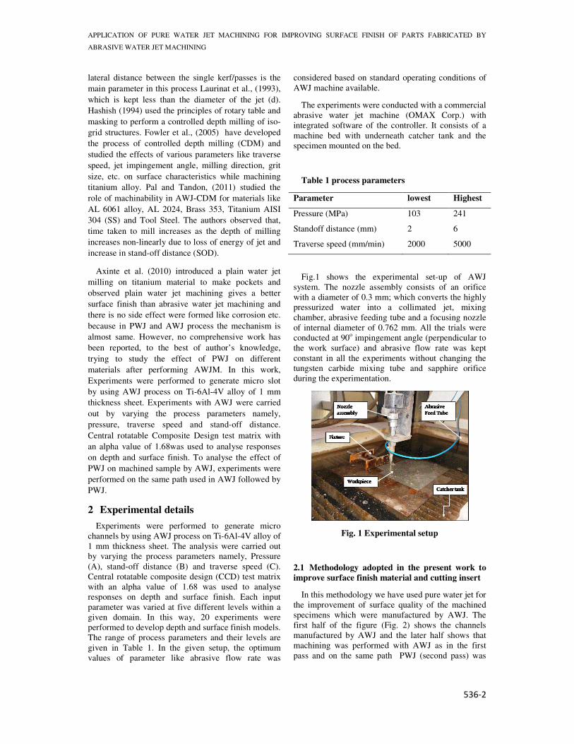
Fig.1 shows the experimental set-up of AWJ
system. The nozzle assembly consists of an orifice
with a diameter of 0.3 mm; which converts the highly
pressurized water into a collimated jet, mixing
chamber, abrasive feeding tube and a focusing nozzle
of internal diameter of 0.762 mm. All the trials were
conducted at 90o impingement angle (perpendicular to
the work surface) and abrasive flow rate was kept
constant in all the experiments without changing the
tungsten carbide mixing tube and sapphire orifice
during the experimentation.
Fig. 1 Experimental setup
2.1 Methodology adopted in the present work to
improve surface finish material and cutting insert
In this methodology we have used pure water jet for
the improvement of surface quality of the machined
specimens which were manufactured by AWJ. The
first half of the figure (Fig. 2) shows the channels
manufactured by AWJ and the later half shows that
machining was performed with AWJ as in the first
pass and on the same path PWJ (second pass) was
5th International & 26th All India Manufacturing Technology, Design and Research Conference (AIMTDR 2014) December 12th–14th, 2014,
IIT Guwahati, Assam, India
536-3
used to improve its surface morphology. The nozzle
path was same in both the cases.
AWJ machining was used for rough/stock removal
of material because of its high MRR followed by pure
water jet (PWJ). In PWJ process, the pressure energy
of water with no abrasive particles is converted into
kinetic energy when the high pressure water passes
through an orifice and hit the surface. Since PWJ is
not suitable for machining hard materials because of
low MRR, therefore in the present methodology PWJ
was used only for finish pass (last pass) at higher
pressure (35 Kpsi).
Fig. 2 Methodology to improve surface quality
3 Measurement
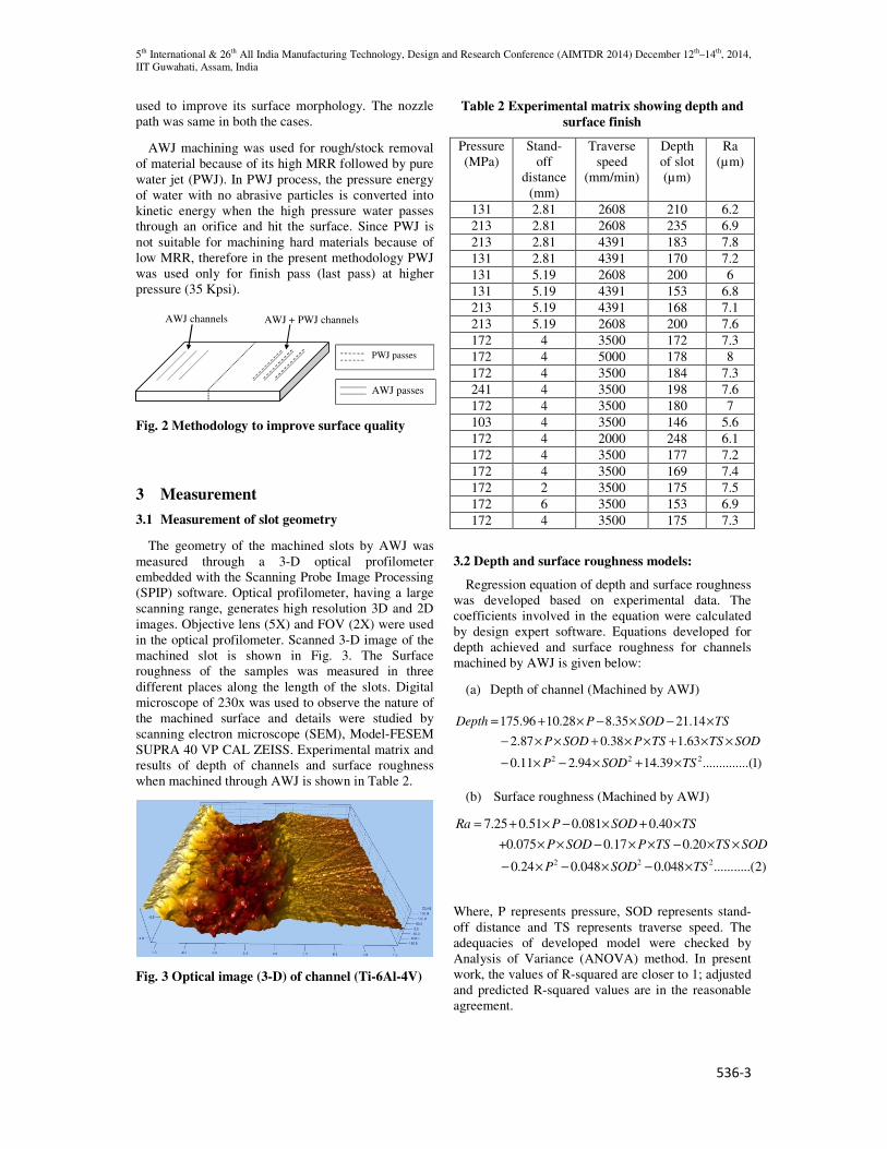
3.1 Measurement of slot geometry
The geometry of the machined slots by AWJ was
measured through a 3-D optical profilometer
embedded with the Scanning Probe Image Processing
(SPIP) software. Optical profilometer, having a large
scanning range, generates high resolution 3D and 2D
images. Objective lens (5X) and FOV (2X) were used
in the optical profilometer. Scanned 3-D image of the
machined slot is shown in Fig. 3. The Surface
roughness of the samples was measured in three
different places along the length of the slots. Digital
microscope of 230x was used to observe the nature of
the machined surface and details were studied by
scanning electron microscope (SEM), Model-FESEM
SUPRA 40 VP CAL ZEISS. Experimental matrix and
results of depth of channels and surface roughness
when machined through AWJ is shown in Table 2.
Fig. 3 Optical image (3-D) of channel (Ti-6Al-4V)
Table 2 Experimental matrix showing depth and
surface finish
Pressure
(MPa)
Stand-
off
distance
(mm)
Traverse
speed
(mm/min)
Depth
of slot
(µm)
Ra
(µm)
131 2.81 2608 210 6.2
213 2.81 2608 235 6.9
213 2.81 4391 183 7.8
131 2.81 4391 170 7.2
131 5.19 2608 200 6
131 5.19 4391 153 6.8
213 5.19 4391 168 7.1
213 5.19 2608 200 7.6
172 4 3500 172 7.3
172 4 5000 178 8
172 4 3500 184 7.3
241 4 3500 198 7.6
172 4 3500 180 7
103 4 3500 146 5.6
172 4 2000 248 6.1
172 4 3500 177 7.2
172 4 3500 169 7.4
172 2 3500 175 7.5
172 6 3500 153 6.9
172 4 3500 175 7.3
3.2 Depth and surface roughness models:
Regression equation of depth and surface roughness
was developed based on experimental data. The
coefficients involved in the equation were calculated
by design expert software. Equations developed for
depth achieved and surface roughness for channels
machined by AWJ is given below:
(a) Depth of channel (Machined by AWJ)
2 2 2
175.96 10.28 8.35 21.14
2.87 0.38 1.63
0.11 2.94 14.39 ..............(1)
Depth P SOD TS
P SOD P TS TS SOD
P SOD TS
= + × − × − ×
− × × + × × + × ×
− × − × + ×
(b) Surface roughness (Machined by AWJ)
2 2 2
7.25 0.51 0.081 0.40
+0.075 0.17 0.20
0.24 0.048 0.048 ...........(2)
Ra P SOD TS
P SOD P TS TS SOD
P SOD TS
= + × − × + ×
× × − × × − × ×
− × − × − ×
Where, P represents pressure, SOD represents stand-
off distance and TS represents traverse speed. The
adequacies of developed model were checked by
Analysis of Variance (ANOVA) method. In present
work, the values of R-squared are closer to 1; adjusted
and predicted R-squared values are in the reasonable
agreement.
AWJ channels AWJ + PWJ channels
AWJ passes
PWJ passes
APPLICATION OF PURE WATER JET MACHINING FOR IMPROVING SURFACE FINISH OF PARTS FABRICATED BY
ABRASIVE WATER JET MACHINING
536-4
4 Result and discussions
In this section, effect of process parameters of AWJ
on depth and surface roughness is discussed based on
developed regression equations (Sec. 3.2). 3-D
surfaces for interaction effects on depth and surface
roughness of process parameters in different
responses are plotted.
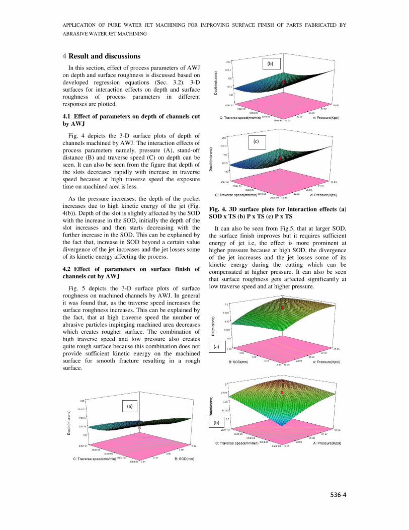
4.1 Effect of parameters on depth of channels cut
by AWJ
Fig. 4 depicts the 3-D surface plots of depth of
channels machined by AWJ. The interaction effects of
process parameters namely, pressure (A), stand-off
distance (B) and traverse speed (C) on depth can be
seen. It can also be seen from the figure that depth of
the slots decreases rapidly with increase in traverse
speed because at high traverse speed the exposure
time on machined area is less.
As the pressure increases, the depth of the pocket
increases due to high kinetic energy of the jet (Fig.
4(b)). Depth of the slot is slightly affected by the SOD
with the increase in the SOD, initially the depth of the
slot increases and then starts decreasing with the
further increase in the SOD. This can be explained by
the fact that, increase in SOD beyond a certain value
divergence of the jet increases and the jet losses some
of its kinetic energy affecting the process.
4.2 Effect of parameters on surface finish of
channels cut by AWJ
Fig. 5 depicts the 3-D surface plots of surface
roughness on machined channels by AWJ. In general
it was found that, as the traverse speed increases the
surface roughness increases. This can be explained by
the fact, that at high traverse speed the number of
abrasive particles impinging machined area decreases
which creates rougher surface. The combination of
high traverse speed and low pressure also creates
quite rough surface because this combination does not
provide sufficient kinetic energy on the machined
surface for smooth fracture resulting in a rough
surface.
Fig. 4. 3D surface plots for interaction effects (a)
SOD x TS (b) P x TS (c) P x TS
It can also be seen from Fig.5, that at larger SOD,
the surface finish improves but it requires sufficient
energy of jet i.e, the effect is more prominent at
higher pressure because at high SOD, the divergence
of the jet increases and the jet losses some of its
kinetic energy during the cutting which can be
compensated at higher pressure. It can also be seen
that surface roughness gets affected significantly at
low traverse speed and at higher pressure.
(a)
(b)
(a)
(c)
(b)
5th International & 26th All India Manufacturing Technology, Design and Research Conference (AIMTDR 2014) December 12th–14th, 2014,
IIT Guwahati, Assam, India
536-5
Fig. 5. 3D surface plots for interaction effects (a) P
x SOD (b) P x TS (c) SOD x TS
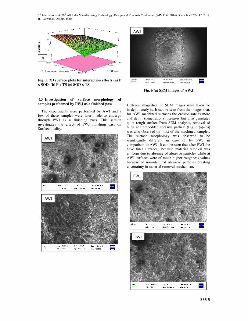
4.3 Investigation of surface morphology of
samples performed by PWJ as a finished pass
The experiments were performed by AWJ and a
few of these samples were later made to undergo
through PWJ as a finishing pass. This section
investigates the effect of PWJ finishing pass on
Surface quality.
Fig. 6 (a) SEM images of AWJ
Different magnification SEM images were taken for
in-depth analysis. It can be seen from the images that,
for AWJ machined surfaces the erosion rate is more
and depth (penetration) increases but also generates
quite rough surface.From SEM analysis, removal of
burrs and embedded abrasive particle (Fig. 6 (a)-(b))
was also observed on most of the machined samples.
The surface morphology was observed to be
significantly different in case of by PWJ in
comparison to AWJ. It can be seen that after PWJ the
have finer surfaces because material removal was
uniform due to absence of abrasive particles while at
AWJ surfaces were of much higher roughness values
because of non-identical abrasive particles creating
uncertainty in material removal mechanism.
(c)
AWJ
AWJ
AWJ
PWJ
PWJ

APPLICATION OF PURE WATER JET MACHINING FOR IMPROVING SURFACE FINISH OF PARTS FABRICATED BY
ABRASIVE WATER JET MACHINING
536-6
Fig. 6 (b) SEM images of PWJ
4 Conclusion
The process parameters of AWJ were analysed to
fabricate micro channels on Ti-6Al-4V alloy. The
most influential of these parameters were determined
by establishing regression models of depth and
surface roughness using multiple linear regression. To
improve the Surface quality of machined samples by
AWJ, a novel methodology has been adopted in
which pure water jet was used as a final pass. Based
on the experiments and microscopic investigation
following conclusions can be drawn:
• Depth of the slot is relatively unaffected by
the stand-off distance (SOD). With increase
in the SOD, initially the depth of the slot
increases and then starts decreasing with the
further increment in the SOD because
divergence of the jet increases and the jet
losses some of its kinetic energy.
• The proper combination of higher traverse
speed and higher pressure creates reasonably
high finished surface because this
combination provides sufficient kinetic
energy to the jet.
• Detailed SEM analysis demonstrated that,
AWJ machined surface generated quite
rough surface than PWJ because material
removal is uniform (no abrasive particles) in
PWJ while at AWJ surfaces were found to be
of higher roughness value because of non-
identical abrasive particles participating in
material removal.
References
Finnie I., (1960), Erosion of surfaces by solid
particles, Wear Vol. 3, 87-103.
Fowler G., Shipway PH., Pashby, IR., (2005), A
technical note on grit embedment following abrasive
water jet milling of titanium alloy, Journal of
Material Processing Technology, Vol. 159, 356-368.
Fowler G., Shipway P. H., Pashby I. R., (2005),
Abrasive water-jet controlled depth milling of
Ti6Al4V alloy – an investigation of the role of jet
workpiece traverse speed and abrasive grit size on the
characteristics of the milled material, International
Journal of Material Processing Technology, Vol. 161,
407-414.
Hashish M., (1994), Controlled-depth Milling
Techniques Using Abrasive-Waterjets, In:Allen N G
(ed) 1994 Jet Cutting Technology, Mechnical
Engineering Publication Ltd, London. 449-461.
Kong M.C., Axinte D., Voice W., (2010), Aspects of
material removal mechanism in plain Waterjet milling
on gamma titanium aluminide, International Journal
of machine tool and manufacture, Vol. 210, 573-584.
Laurinat A., Louis H., Meier-Wiechert, G., (1993), A
Model for Milling with Abrasive Water Jet In:
Hashish M (ed.) 1993 Proceedings of the 7th
American Water Jet, Vol.1, Water jet Association, St,
Luis, 119-139
Pal V K., Tandon P., (2011), Identification of role of
machinability and milling depth on machining time in
controlled depth milling using abrasive water jet.
International Journal of Advanced Manufacturing
Technology, Vol. 66, 877-881.
PWJ