Embed Size (px)
Citation preview

TPC BENCHMARKTM App
(Application Server)
Specification
Version 1.3 Feb 28, 2008
Transaction Processing Performance Council (TPC)
PO Box 29920
San Francisco, CA 94129-0920, USA
Phone (415) 561-6272
Fax (415) 561-6120
http://www.tpc.org
e-mail:[email protected]
© 1993 - 2004 Transaction Processing Performance Council
2
Acknowledgments
Developing a TPC benchmark for a new environment requires a huge effort to conceptualize, research, specify, review, prototype, and verify the benchmark.
The TPC-App specification was developed by the TPC-W subcommittee. The TPC-W subcommittee would like to acknowledge the contributions made by the many members during the development of the benchmark specification. It has taken the dedicated efforts of people across many companies, often in addition to their regular duties.
The list of significant contributors to this version includes Chris Floyd, Steve Barrish, Wayne Smith, Steve Morris, Chris Elford, Guy Groulx, Dale Woodford, Alan Chan, Lorna Livingtree, Mike Vernal, Cecil Reames, Steve Realmuto, Yasser Shohoud, Paul Awoseyi, Malcolm MacNiven, Toby Nixon, Anurag Gupta, Jerrold Buggert, Brad Lund, Jim Chen, Mike Molloy, John Benninghoff, Tom Colati, Ram Venkatesh, Matt Hogstrom, Greg Darnell, Priti Mishra, and Shanti Subramanyam.
TPC Membership (As of December, 2004)
AMD BEA Systems, Inc.
Bull S.A. Centro de Informatica Dell Computers Corp.
Fujitsu Ltd. Fujitsu Siemens
Hewlett-Packard Co.
Hitachi Ltd. IBM Corp.
Ideas International Intel Corp.
ITOM International Microsoft Corp.
NEC Systems Laboratory Netezza
Network Appliance Oracle Corp.
OSDL RackSaver
Silicon Graphics Inc. Sun Microsystems Inc.
Sybase Inc. Unisys Corp.
Trademarks and Legal Notices
TPC Benchmark™, TPC-App, and SIPS are trademarks of the Transaction Processing Performance Council.
All parties are granted permission to copy and distribute to any party without fee all or part of this material provided that: 1) copying and distribution is done for the primary purpose of disseminating TPC material; 2) the TPC copyright notice, the title of the publication, and its date appear, and notice is given that copying is by permission of the Transaction Processing Performance Council.
Parties wishing to copy and distribute TPC materials other than for the purposes outlined above (including incorporating TPC material in a non-TPC document, specification or report), must secure the TPC's written permission.
3
Document History December 15, 2004 Version 1.0 Version submitted for TPC Company Vote August 11, 2005 Version 1.1 Integration with TPC Pricing specification and
minor editorial changes. Feb 28, 2008 Version 1.3 Wording to permit virtualization products
4
Table of Contents
Clause 0 - Preamble ............................................................................................................................. 10
0.1 Introduction ................................................................................................................................. 10
Clause 1 - Web Object and Logical Database Design ..................................................................... 13
1.1 Business and Application Environment.................................................................................. 13
1.2 Definitions of Terms................................................................................................................... 14
1.4 Database Entities, Relationships, and Characteristics........................................................... 26
1.5 Table Layouts .............................................................................................................................. 28
1.6 Ancillary Data Structures .......................................................................................................... 31
1.6.1 Images....................................................................................................................................... 31
The image components of the TPC-App benchmark are defined to consist of images in JPEG format. The currently defined size for all images is 5K, 10K, 50K, 100K and 250KB. The images are meant to represent the data flow of multi-media documents such as images, audio or video-stream, through the usage of Web services. Each of these images is generated using the TPC-App Image Generator (available on the TPC Web site). The total number of unique images generated is equal to the cardinality of the ITEM table to represent each item’s image or other rich media on the site (see Clause 4.6.9). The distribution for the different image sizes follows:................................................................................................................................................................... 31
1.6.2 Shipping Cost Matrix ............................................................................................................. 32
1.7 Database Implementation Rules............................................................................................... 32
1.8 Integrity Rules ............................................................................................................................. 34
1.9 Data Access Transparency REQUIREMENTS........................................................................ 34
Clause 2 - Web Service Interactions and Workload Profile ........................................................... 35
2.1 Implementation REQUIREMENTS.......................................................................................... 35
2.2 New Customer Web Service ..................................................................................................... 42
2.3 Change Payment Method Web Service ................................................................................... 44
2.4 Create Order Web Service ......................................................................................................... 46
2.5 Shipping Process ......................................................................................................................... 51
2.6 Stock Management Process ....................................................................................................... 53

5
2.7 Order Status Web Service .......................................................................................................... 55
2.8 New Products Web Service ....................................................................................................... 58
2.9 Product Detail Web Service....................................................................................................... 59
2.10 Change Item Web Service.......................................................................................................... 61
Clause 3 - TRANSACTION AND SYSTEM PROPERTIES............................................................ 63
Transaction ACID Properties ................................................................................................................ 63
3.1 Introduction ................................................................................................................................. 63
3.1.1 All processes interactions and Web Service Interactions with any database maintaining the tables defined in Clause 1 MUST be made through a Transaction supporting full ACID properties, as defined in clauses 3.2 through 3.5. .................................................................................. 63
3.2 Atomicity...................................................................................................................................... 64
Clause 4 - Scaling and Database Population.................................................................................... 75
4.1 General Scaling Rule .................................................................................................................. 75
4.2 Scaling REQUIREMENTS.......................................................................................................... 75
4.3 Database Cardinality.................................................................................................................. 76
4.4 60-Day Space Computation....................................................................................................... 76
4.5 Log REQUIREMENTS................................................................................................................ 77
4.6 Database Population................................................................................................................... 79
4.7 Table Population REQUIREMENTS ........................................................................................ 82
4.8 Customized Load Utilities......................................................................................................... 84
Clause 5 - PERFORMANCE METRICS AND RESPONSE TIME ................................................. 85
5.1 Web Service Interaction Mix REQUIREMENTS .................................................................... 85
5.2 Web Service Interaction Response Time ................................................................................. 87
5.3 Computation of Throughput Rating........................................................................................ 90
5.4 Test Run REQUIREMENTS....................................................................................................... 90
5.5 Measurement Interval REQUIREMENTS ............................................................................... 92

6
Clause 6 - SUT, RBE AND NETWORK DEFINITIONS ................................................................. 93
6.1 Remote Business Emulator (RBE)............................................................................................. 93
6.2 Business Session Length ............................................................................................................ 94
6.3 Customer IDs, Business Name, and Customer Password .................................................... 95
6.4 Random Number Generation ................................................................................................... 96
6.5 System Under Test (SUT) .......................................................................................................... 96
6.6 Purchase Order Validation (POV)............................................................................................ 99
6.7 Payment Gateway Emulator (PGE)........................................................................................ 100
6.8 Inventory Control Emulator (ICE) ......................................................................................... 100
6.9 Shipment Notification Emulator ............................................................................................ 101
6.10 Model of the Complete Tested System .................................................................................. 102
6.11 Communications Interface Definitions.................................................................................. 102
6.12 Operational Characteristics ..................................................................................................... 103
Clause 7 - PRICING ........................................................................................................................... 105
7.1 Priced Configuration ................................................................................................................ 105
7.2 Pricing requirements not included in the TPC Pricing Specification................................ 105
Clause 8 - Clause 8 Full Disclosure Report .................................................................................... 106
8.1 General REQUIREMENTS ...................................................................................................... 106
8.2 Executive Summary.................................................................................................................. 108
8.3 Clause 1 - Web Object and Logical Database Design .......................................................... 110
8.4 Clause 2 - Service Interactions and Workload...................................................................... 111
8.5 Clause 3 - Transaction and System Properties ..................................................................... 111
8.6 Clause 4 - Scaling and Database Population......................................................................... 112
8.7 Clause 5 Performance Metrics and Response Times ........................................................... 112
8.8 Clause 6 - SUT, RBE and Network ......................................................................................... 117
7
8.9 Clause 7 - Pricing ...................................................................................................................... 117
8.10 Clause 9 - Audit Related Items ............................................................................................... 117
8.11 Availability of the Full Disclosure Report............................................................................. 117
8.12 Revisions to the Full Disclosure Report ................................................................................ 118
Clause 9 - Clause 9 - Auditing ......................................................................................................... 119
9.2 Auditors Checklist .................................................................................................................... 120
Appendix A - RANDOM NUMBER GENERATOR...................... 125
A.1 Random Number Generator - 64bit Linear Congruential Method ................................... 125
Appendix B - References ............................................................................................... 126
B.1 [WS-I BP 1.0 Specification] ...................................................................................................... 126
B.2 [RFC 2616] .................................................................................................................................. 126
B.3 [RFC 791] .................................................................................................................................... 126
B.4 [RFC 2460] .................................................................................................................................. 126
B.5 [RFC 793] .................................................................................................................................... 126
Transmission Control Protocol, Jon Postel,September 1981 (See http://www.ietf.org/rfc/rfc0793.txt) ............................................................................................... 126
B.6 [RFC 2527] .................................................................................................................................. 126
B.7 [RFC 2437] .................................................................................................................................. 126
B.8 [SSL] ............................................................................................................................................ 126
B.9 [RFC 2246] .................................................................................................................................. 126
Transport Layer Security, T. Dierks, C. Allen, January 1999 (See http://www.ietf.org/rfc/rfc2246.txt ................................................................................................ 126
B.10 [SOAP].................................................................................................................................... 126
Simple Object Access Protocol (SOAP) 1.1, D. Box, D. Ehnebuske, G. Kakivaya, A. Layman, N. Mendelsohn, H. Neilsen, S. Thatte, D. Winer, 8 May 2000 (See http://www.w3.org/TR/2000/NOTE-SOAP-20000508/)............................................................ 126
B.11 [W3C XML Schema Recommendation] ............................................................................. 126
B.12 [OSI reference model]........................................................................................................... 126

8
B.13 [ECMA-335] ........................................................................................................................... 126
B.14 [CLF] ....................................................................................................................................... 126
Logging Control In W3C httpd, World Wide Web Consortium, ( See http://www.w3.org/Daemon/User/Config/Logging.html#common-logfile-format ).......... 126
Appendix C - Cumulative Distribution Function.................................................................. 127
Appendix D - BSL Variate Sample Code .................................................... 129
Appendix E - WSDL Samples.................................................................................. 130
E.1 TPC-App Application WSDL.................................................................................................. 130
E.2 POV WSDL ............................................................................................................................... 137
E.3 PGE WSDL................................................................................................................................. 139
E.4 ICE WSDL .................................................................................................................................. 140
Appendix F - EXECUTIVE SUMMARY ...................................................... 142
F.1 Implementation Overview Page............................................................................................. 143
The following pages demonstrate how the format of the Executive Summary pages MUST appear for a TPC-App result: .............................................................................................................. 143
F.2 Pricing Page ............................................................................................................................... 144
F.3 Numerical Quantities Summary Page ................................................................................... 145
Appendix G - Throughput scaling limits ................................................... 146
G.1 An upper bound on Total SIPS ............................................................................................... 146
G.2 Preventing the over-scaling of the SUT................................................................................. 146
To prevent over-scaling the SUT, the reported Total SIPS MUST NOT fall short of the following lower bound on Total SIPS, defined as 50% of the upper bound on Total SIPS : ......................... 146
Appendix H - .............................................................................................................................. 147
Why the 3 hour steady state requirement? ....................................................................................... 147
Why are orders that are created by a new customer never accessed outside of the session that created the new customer? .................................................................................................................. 147
Why are items not added or removed from the ITEM table? ........................................................ 147
9
Why is the value of S_QTY handled the way that it is? .................................................................. 147
Why is the WSDL for the application not mandated?..................................................................... 147
Why is there a requirement that access from the Application Program to any component used in the benchmark be performed with APIs available to the Managed Environment? ............... 148
Why does the database not have referential integrity requirements? .......................................... 148
Why are there benchmark requirements for RAID storage?.......................................................... 148
Why is the ICE removed from the atomic operations for the Stock Management process? ..... 148
Why is there no requirement for a traditional Web server product?............................................ 148
Why is O_DISCOUNT set to ‘0’ for the initial database population?........................................... 148
Why is it required to resubmit requests when an error occurs, and why is there a maximum of 20 retries on any single Web Service Request?................................................................................. 148
Why is there is an 8 hour storage requirement even though the SUT represents a 24x7 operation? .............................................................................................................................................. 148
Why is the database not the focus of this benchmark as in other TPC benchmarks?................. 149
Why do the timestamps taken for the SIRT (T1 and T2) include processing that occurs on the RBE (i.e., T2 = next Web Service Interaction’s T1)? ......................................................................... 149
Why are there <Start Database Transaction> and <End Database Transaction> tags around single selects from the database?........................................................................................................ 149
While the benchmark requires SSL/TLS with certificates from server to client, it does not require client certificate authentication. Is this normal for a B2B environment? ....................... 149
Are the key sizes and restrictions for SSL representative and appropriate for this business model? .................................................................................................................................................... 149

10
Clause 0 - Preamble
0.1 Introduction
TPC Benchmark™ App (TPC-App) is an Application Server and Web services benchmark. The workload is performed in a Managed Environment that simulates the activities of a business–to-business Transactional Application Server operating in a 24x7 environment (see clause 1.2.13). TPC-App showcases the performance capabilities of application server SYSTEMs (see clause 1.2.14). The workload exercises Commercially Available Application Server products, Messaging Products, and databases associated with such environments, which are characterized by:
• Multiple on-line Business Sessions
• Commercially Available application environment
• Use of XML documents and SOAP for data exchange
• Business to business application logic
• Distributed Transaction Management
• Reliable and durable messaging
• Dynamic Web Service Response generation with database access and update
• Simultaneous execution of multiple Transaction types that span a breadth of business functions.
• Databases consisting of many tables with a wide variety of sizes, attributes, and relationships
• Transaction integrity (ACID properties)
0.1.1 TPC-App Fundamentals
There are two performance metrics reported by TPC-App. The first is the Web Service Interactions per second (SIPS) per Application Server SYSTEM. The second is the Total SIPS, which is the total number of SIPS for the entire tested configuration (SUT). Multiple Web Service Interactions are used to simulate the business activity of an online supplier, and each Web Service Interaction is subject to a response time constraint.
All references to TPC-App results must include the primary metrics, which are, the SIPS per Application Server SYSTEM, Total SIPS, the associated price per SIPS (e.g., $USD/SIPS) and the Availability Date of the priced configuration.
TPC-App uses terminology and metrics that are similar to other benchmarks originated by the TPC or others. Such similarity in terminology does not in any way imply that TPC-App results are comparable to other benchmarks. The only benchmark results comparable to TPC-App are other TPC-App results with the appropriate revision.
11
The managed environments that must be used to implement the application logic are ECMA-335 (e.g., Microsoft .NET Framework) or J2SE 1.4. Extensions to these specifications as well as any follow-on revisions of these specifications are allowed. If this TPC-App specification were to require specific levels of these managed environments, it would quickly become obsolete as new revisions to the managed environments are developed. J2EE is the “gold” standard for JAVA, it is however more restrictive than the J2SE specification. Since the J2SE specification is much more of an analog to the ECMA-335 specification, requiring J2EE with its additional restrictions, would give the ECMA-335 products an unfair advantage.
Despite the fact that this benchmark offers a rich environment that emulates many Web service applications, this benchmark does not reflect the entire range of Web service or Application Server requirements. In addition, the extent to which a customer can achieve the results reported by a vendor is highly dependent on how closely TPC-App approximates the customer application. The relative performance of systems derived from this benchmark does not necessarily hold for other workloads or environments. Extrapolations to any other environment are not recommended.
Benchmark results are highly dependent upon workload, specific application requirements, systems design, and implementation. Relative system performance will vary as a result of these and other factors. Therefore, TPC-App should not be used as a substitute for a specific customer application benchmarking when critical capacity planning and/or product evaluation decisions are contemplated.
Benchmark sponsors are permitted several possible system designs, insofar as they adhere to the model described and pictorially illustrated in clause 6. A Full Disclosure Report of the implementation details, as specified in clause 8, must be made available along with the reported results.
Comment: While separated from the main text for readability, comments and Appendices A and C are parts of the standard and are enforced. The remainder of the Appendices are provided for informational purposes only and are not enforced.
0.1.2 General Implementation Guidelines
The purpose of TPC benchmarks is to provide relevant, objective performance data to industry users. To achieve that purpose, TPC benchmark specifications require that benchmark tests be implemented with systems, products, technologies and pricing that:
• Are generally available to users.
• Are relevant to the market segment that the individual TPC benchmark models or represents (e.g. TPC-App models and represents high-volume, complex Web services and Application Server environments).
• A significant number of users in the market segment the benchmark models or represents would plausibly implement.
The use of new systems, products, technologies (hardware or software), and pricing is encouraged so long as they meet the requirements above. Specifically prohibited are benchmark systems, products, technologies, pricing, and implementations whose primary purpose is performance optimization of TPC benchmark results without any corresponding applicability to real-world applications and environments. In other words, all "benchmark special" implementations that improve benchmark results but not real-world performance or pricing, are prohibited.

12
Although this specification expresses implementation in terms of a relational data model with a conventional locking scheme, the database may be implemented using any Commercially Available database management system (Database Server), Database Server, file system, or other data repository that provides a functionally equivalent implementation. The terms "table", "row", and "column" are used in this document only as examples of logical data structures.
The definition of Application Server and it’s permissible architecture in the SUT is not intended to prescribe a particular application model (e.g., standalone OS process, hosted component, etc.) for the Application Program.
The following characteristics should be used as a guide to judge whether a particular implementation is a benchmark special. It is not required that each point below be met, but that the cumulative weight of the evidence be considered to identify an unacceptable implementation. Absolute certainty or certainty beyond a reasonable doubt is not required to make a judgment on this complex issue. The question that must be answered is this: based on the available evidence, does the clear preponderance (the greater share or weight) of evidence indicate that this implementation is a benchmark special?
The following characteristics should be used to judge whether a particular implementation is a benchmark special:
• Is the implementation generally available, documented, and supported?
• Does the implementation have significant restrictions on its use or applicability that limits its use beyond TPC benchmarks?
• Is the implementation or part of the implementation poorly integrated into the larger product?
• Does the implementation take special advantage of the limited nature of TPC benchmarks (e.g., Transaction profile, Transaction mix, Transaction concurrency and/or contention, Transaction isolation) in a manner that would not be generally applicable to the environment the benchmark represents?
• Is the use of the implementation discouraged by the vendor? (This includes failing to promote the implementation in a manner similar to other products and technologies.)
• Does the implementation require uncommon sophistication on the part of the end-user, programmer, or system administrator?
• Is the pricing unusual or non-customary for the vendor or unusual or non-customary to normal business practices? See the current level of the TPC Pricing Specification, Version 1, for additional details.
• Is the implementation being used (including beta) or purchased by end-users in the market area the benchmark represents? How many? Multiple sites? If the implementation is not currently being used by end-users, is there any evidence to indicate that it will be used by a significant number of users?

13
Clause 1 - Web Object and Logical Database Design
1.1 Business and Application Environment
TPC Benchmark™ App comprises a set of basic operations designed to exercise Transactional application server functionality in a manner representative of business-to-business Web service environments. These basic operations have been given a real-life context, portraying the business activity of a distributor that supports user online ordering and browsing activity. This is intended to help users relate intuitively to the components of the benchmark. The workload is centered on business logic involved with processing orders and retrieving product catalog items and provides a logical database design.
The workload was designed specifically to stress the Application Server. As such, the work to be performed by the database was purposely minimized. Additionally, the application was designed such that it would cluster in a manner that is as nearly linear as possible. All application server SYSTEMS are required to have identical hardware and software configurations. The workload is then distributed across all application server SYSTEMS. TPC-App does not permit specialized application server SYSTEMS that do not perform all of the application server SYSTEM requirements.
TPC-App does not benchmark the logic needed to process or display the presentation layer (for example, HTML) to the clients. The clients in TPC-App represent businesses that utilize Web services in order to satisfy their business needs. TPC-App does not represent the activity of any particular business segment, but rather any industry that must market and sell a product or service over the Internet via Web services (e.g., retail store, software distribution, airline reservation, etc.). TPC-App does not attempt to be a model of how to build an actual application.
The purpose of this benchmark is to retain the application's essential performance characteristics, namely: the level of system utilization and the complexity of operations, while reducing the diversity of operations found in Application Servers. A large number of functions have to be performed to manage an environment that supports order processing and browsing functions. TPC-App includes a representative set of these functions. Many other functions are not of primary interest for performance analysis, since they are proportionally small in terms of system resource utilization or in terms of frequency of execution. Although these functions are vital for a production system, they merely create unnecessary diversity in the context of a standard benchmark and have been omitted in TPC-App.
The application portrayed by the benchmark is a retail distributor on the Internet with ordering and product browsing scenarios. The application accepts incoming Web Service Requests from other businesses (or a store front) to place orders, view catalog items and make changes to the catalog, update or add customer information, or request the status of an existing order. The majority of requests generate order purchase activity with a smaller portion of requesting item catalog information.
There are four categories of results. Two concerning clustered systems, Clustered and Clustered-Virtualized and two concerning Non-Clustered systems, Non-Clustered and Non-Clustered-Virtualized.

14
1.2 Definitions of Terms
1.2.1 MUST – This word, or the words REQUIRED, REQUIRES, REQUIREMENT or SHALL, means that compliance is mandatory.
1.2.2 MUST NOT – This phrase, or the phrase SHALL NOT, means that this is an absolute prohibition of the specification.
1.2.3 SHOULD – This word, or the word RECOMMENDED, means that there might exist valid reasons in particular circumstances to ignore a particular item, but the full implication must be understood and weighed before choosing a different course.
1.2.4 SHOULD NOT – This phrase, or the phrase NOT RECOMMENDED, means that there might exist valid reasons in particular circumstances when the particular behavior is acceptable or even useful, but the full implications should be understood and the case carefully weighed before implementing any behavior described with this label.
1.2.5 MAY – This word means that an item is truly optional.
1.2.6 When used in this specification the term SYSTEM, when used in all caps, refers to a dedicated set of hardware, including one or more processors, using SHARED MEMORY (e.g. SMP or NUMA). It is capable of executing one instance of operating software. The operating software could be a general purpose OPERATING SYSTEM, VIRTUALIZATION PRODUCT or a special purpose engine that is a hybrid between a general purpose OPERATING SYSTEM and an Application Server. A SYSTEM could be an entire multi-processor computer, a static partition of a multiprocessor computer or a computer with a single processor. The set of hardware used by the SYSTEM MUST NOT change during the Test Run.
1.2.7 FIRMWARE is a computer program that is embedded in a hardware device, for example a microcontroller. It can also be provided on flash ROMs or as a binary image file that can be uploaded onto existing hardware by a user. It is stored in the non-volitile memory of the device and is not lost across power interruptions.
1.2.8 The term SHARED MEMORY refers to a block of random access memory that can be directly accessed by all Processors/Cores in a computer system. This access mechanism MUST be provided by hardware/FIRMWARE components. If there any caches between the Processors/Cores and main memory then cache coherency MUST be maintained by hardware/FIRMWARE components.
1.2.9 When used in this specification the term OPERATING SYSTEM refers to the program that, after being initially loaded into the computer by a boot program, manages all the Applications on a SYSTEM, or if loaded into a computing environment created by a VIRTUALIZATION PRODUCT manages all of the Applications in that computing environment. The OPERATING SYSTEM provides a software platform on top of which all Applications run. The Applications make use of the OPERATING SYSTEM by making requests for services through a defined application program interface (API). All major computer platforms require an OPERATING SYSTEM. The functions and services supplied by an OPERATING SYSTEM include but are not limited to the following:
• Manages a dedicated set of CPU and memory resources. • Provides access to persistent storage. • Loads Applications into memory.

15
• Ensures that the resources allocated to one Application are not used by another Application in an unauthorized manner.
• Determines which Applications should run in what order, and how much time should be allowed to run the Application before giving another Application a turn to use the systems resources.
• Manages the sharing of internal memory among Applications. • Handles input and output to and from attached hardware devices such as hard
disks, network interface cards, etc.
Some examples of OPERATING SYSTEMS are listed below:
• Windows • Unices (Solaris, AIX) • Linux • MS-DOS • Mac OS • VMS • Netware
1.2.10 When used in this specification the term VIRTUALIZATION PRODUCT is defined as a framework or methodology of dividing the resources of a SYSTEM into multiple computing environments. Each of these computing environments allows a completely isolated software stack including an OPERATING SYSTEM to run in complete isolation from anything else running on the SYSTEM. The VIRTUALIZATION PRODUCT allows the creation of multiple computing environments on the same SYSTEM. The following are examples of a VIRTUALIZATION PRODUCT:
• VMWare ESXServer • Xen • Solaris 10 Logical Domains also known as LDOMs. Note that Solaris 10
zones and containers do not meet the criteria for a VIRTUALIZATION PRODUCT because they do not provide for a fully isolated software stack including an OPERATING SYSTEM.
Comment: The term VIRTUALIZATION PRODUCT is not meant to include the static partitioning of a SYSTEM that occurs at boot time or any dynamic partitioning that may take place through operator intervention.
Comment: For the purposes of this specification intelligent HBA’s, SANs, maintenance processors etc are not considered to be VIRTUALIZATION PRODUCTS.
1.2.11 When used in this specification the term Application refers to any code or commercially available product that requires the services of an OPERATING SYSTEM to perform its functions.
16
1.2.12 The term Managed Environment in this specification refers to a software abstraction layer that sits between application code and the OPERATING SYSTEM. It provides a logical runtime environment that insulates the application from the native OPERATING SYSTEM.
Functions performed by a Managed Environment include but are not limited to the following:
• Automatic memory management and garbage collection • Code verification • Translation of an intermediate language generated by a compiler into native
machine code • Program loading • Thread creation and scheduling. • Runtime data type checking
Comment 1: It is permissible for threads to be created through APIs provided by the runtime libraries that are part of the Managed Environment.
The execution environment provided MUST be compliant with one of the following specifications. It may be a superset of the specification and contain vendor specific extensions and enhancements.
• J2SE 1.4 JRE or greater as published by Sun Microsystems • Either [ECMA-335] (or its logical successors) as published by the European
Computer Manufacturers Association or ISO/IEC 23271:2003 (or its logical successors) as published by International Standards Organization.
The application server SYSTEM may execute multiple instances of Managed Environments. Within each instance of a Managed Environment, one or more instances of the Application Program (or parts thereof) may execute. Comment 2: If other managed environments become available that meet the requirements defined above, the TPC will evaluate these technologies on a case by case basis to determine if additional managed environments will be permitted.
1.2.13 The term Application Server refers to a commercially-available software layer that provides an environment for hosting a Managed Environment and a set of software libraries that provide infrastructure functions and services. It is positioned between a client (requesting) process and the business logic that satisfies the request. The Application Server provides functions and / or interfaces that include, but are not limited to, the list below.
• Exposing / consuming Web services (conforming to the [WS-I BP 1.0 Specification]) • Participating in Distributed Transactions (e.g., start, rollback, commit) • Securing client / server interactions • Managing shared resources (e.g., thread pool, database connection pool, etc.) • Interacting with the database • Managing application state

17
The Application Server may be an integrated part of the OPERATING SYSTEM or a separate product that is procured from another source or sources. The Application Server MAY host multiple instances of the Managed Environment. Commercially Available components from various sources may be used in conjunction with each other to satisfy the REQUIREMENTS of the Application Server. For Non-Clustered results, all components of the Application Server MUST execute on the application server SYSTEM. For Clustered results, all components of the Application Server MUST execute on each application server SYSTEM. For virtualized results all components of the Application Server must execute on each instance of an OPERATING SYSTEM.
Comment 1: The term Application Server is not intended to prescribe a particular application model (e.g., standalone OS process, hosted component, etc.) for the Application Program (see clause 1.2.22)
Comment 2: It is possible that a product marketed as an “application server” MAY only provide partial functionality of the Application Server. It is permissible to use these products; however other commercial components MUST be included to satisfy the REQUIREMENTS (as listed above) for the Application Server.
1.2.14 The term application server SYSTEM in this specification refers to a SYSTEM that hosts one or more Application Servers.
1.2.15 The term Distributed Transaction Manager in this specification refers to a software component that allows the coordination of a number of resources that may span several heterogeneous systems on the behalf of an application. It ensures that all operations performed by an application are either completed successfully or leave no trace of any change. This coordination may involve the synchronization of one or more databases, as well as message queues and other resources that may be used by a business Transaction. The Distributed Transaction Manager is able to coordinate the recovery of business Transactions in the event of site failure, network failure, or global resource dead locks. The Distributed Transaction Manager MUST be capable of managing the Transactions that cross resource boundaries and MUST be capable of meeting the ACID REQUIREMENTS as defined in Clause 3. Distributed Transaction Manager products may require persistent, durable storage to maintain their internal data structures for their REQUIRED functionality. For the purposes of this specification, this persistent durable storage is considered the Distributed Transaction Manager log space.
1.2.16 The term Durable Message is used in this specification to refer to the message that is sent to and removed from the Shipping and Stock Management queues which are implemented by the Messaging Product(s). These messages must exhibit the Durability Property (see clause 3.5.1) and are subject to the durability test defined in clause 3.5.4.1.2.
1.2.17 The term Reliable Messaging is used in this specification to refer to the requirement that messages acknowledged as accepted by the Messaging Product, MUST be delivered exactly once, and must remain on the queue until they are successfully retrieved.
1.2.18 The term Messaging Product in this specification refers to a commercially available software component that provides an API that allows applications and systems to communicate with each other across a heterogeneous loosely coupled network.The product MUST have capabilities that include but are not limited to the following:
• Reliable Messaging and Durable Messages.
18
• Security capabilities (authentication, authorization, and encryption). The security may be built in to the product. Alternatively, the product may be capable of integrating with another resource to provide access to these security technologies.
• Ability to participate in Distributed Transactions The Application Program access to the Shipping and Stock Management queues MUST be performed through Commercially Available Messaging Product APIs. Comment 1: Examples of messaging implementations that are not considered acceptable Messaging Products for this specification include the Application Program using a relational DBMS and explicit SQL commands to store and retrieve messages, use of a file system and file system read / write APIs for Messaging, etc. Comment 2: While reliable message delivery is REQUIRED, there are no restrictions on the order of delivery or message processing other than the message processing constraints of clause 5.5.
1.2.19 The Shipping Queue is a Durable Message queue that transports messages from the Create Order Web Service Interaction to the Shipping Process. Additionally it transports messages from the Stock Management Process to the Shipping Process. This message queue MUST be implemented with a commercially available Messaging Product as described in clause 1.2.17.
1.2.20 The Stock Management Queue is a Durable Message queue that transports messages from the Shipping Process to the Stock Management Process. This message queue MUST be implemented with a commercially available Messaging Product as described in clause 1.2.17.
1.2.21 The term Database Server refers to the software used to implement the data repository (see clause 1.4) that provides a functionally equivalent implementation to the database specification in this benchmark specification. (See clause 0.1.2.)
1.2.22 The term Application Program is used in this specification to refer to code that is not part of the Commercially Available components of the system, but produced specifically to implement the Web Service Interactions and the Transactions defined in this benchmark. Stored procedures are considered part of the Application Program when used to implement any portion of the Web Service Interactions, Transactions, or enforce ACID properties.
1.2.23 The System Under Test (SUT) comprises all components that are part of the application being simulated. This includes, but is not limited to, network connections, the application server SYSTEMs and database server SYSTEMs. (See clause 6.5)
1.2.24 The term, Priced Configuration is defined as the collection of hardware and software components and associated maintenance that must be priced as a part of the price/performance primary metric.
Comment: The Measured Configuration may differ from the Priced Configuration with regards to components as allowed by the TPC-App specification.
1.2.25 The term SYSTEM_IDENTIFIER is used in this specification to refer to a field that uniquely identifies the OPERATING SYSTEM that responded to the Web Service Request. This field MUST be included in the Web Service Response for all Successful Web Service Interactions, even if the SUT contains a single application server SYSTEM.
19
1.2.26 The term Clustered refers to a SUT configuration that contains more than one application server SYSTEM.For the purposes of this specification the term Clustered refers to both categories of clustered systems (i.e. Clustered and Clustered-Virtualized).
The term Non-Clustered refers to a SUT configuration that contains exactly one application server SYSTEM. For the purposes of this specification the term Non-Clustered refers to both categories of Non-Clustered systems (i.e. Non-Clustered and Non-Clustered-Virtualized).
1.2.27 The term Virtualized refers to a SUT configuration that uses a VIRTUALIZATION PRODUCT to support one or more OPERATING SYSTEMS on one or more SYSTEMs.
1.2.28 The terms external devices and appliances is used in this specification to refer to any part of the SUT that is not directly connected to the Application Server SYSTEM or Database Server SYSTEM host bus (e.g., PCI bus).
1.2.29 The term Processor Cache in this specification refers to an area of volatile storage other than main memory that is quickly and easily accessed by a Processor. This storage is composed of a smaller and faster memory which stores data from the most frequently used main memory locations. Most currently available Processors employ a multi-level caching architecture and may have multiple interacting caches on the same Processor, for the purposes of this specification Processor Cache refers to the amount of memory that is advertised by the vendor of the Processor.
Comment: The definition of this term is only to be used in the context of reporting for the Executive Summary page of the Full Disclosure Report.
1.2.30 The term caching in this specification refers to the retrieval of any data defined in clause 1.5 from anything other than the Database Server where the initial database population was loaded. See clause 6.5.3.1 for restrictions on caching.
1.2.31 The term multiplexing is used in this specification to refer to the management of a resource by allocating that resource to individual requestors at different times. The following are examples of multiplexing:
• A TCP/IP connection multiplexer would sit between the end users and a server. The multiplexer would have a connection open to each end user but would only have a small number of connections open to the server.
• An example of HTTP request multiplexing occurs when the HTTP server multiplexes many HTTP requests to a smaller set of threads to be used for request processing.
• The scheduling algorithm within an OPERATING SYSTEM that would manage the use of a processor by sharing it among a group of threads that are requesting processor time.
1.2.32 The term load balancing is used in this specification to refer to the direction of a request or message to an entity that is a member of a set of entities that are capable of processing the request or message with the goal of spreading work across that set of entities. The following are some examples of load balancing
20
• A device that distributes requests to a group of servers based on some algorithm. This may be as simple as a “round robin” scheme or as complex as the device dynamically directing requests based on the availability of processing resources on each server.
• An Application Server that receives a request and redirects that request to another server for processing.
1.2.33 The term routing is used in this specification to refer to the direction of a request or message to an entity based on information that is contained in the request or message. Some examples of routing are:
• TCP/IP routing • Direction of a request to a specific server based on the type of the request or the
data that is a part of the request.
1.2.34 The term Commercially Available is used in this specification to refer to components of the SUT that are purchased, licensed, or otherwise obtained that meet the REQUIREMENTS as specified in Clause 7 -.
1.2.35 The term Measurement Interval is used in this specification to refer to a continuous subset of the Steady State Period with a length of at least 2 hours for which the test sponsor is reporting a performance metric. See clause 5.4.4 for detailed REQUIREMENTS.
1.2.36 The term Ramp-Up Period is used in this specification to refer to the time between the submission of the first Web Service Interaction and the time when every Active EB (see clause 1.2.45) has submitted at least one Web Service Interaction request.
1.2.37 The term Stabilization Period is used in this specification to refer to the time between the end of the Ramp-Up Period and the beginning of the Steady State Period. This period refers to a state where the throughput of the SUT has not yet attained Steady State (See clause 5.4.1). For example, while the data caches are warming up, the throughput may be in a state of flux, and may not be considered Steady State by the auditor.
1.2.38 The term Steady State Period is used in this specification to refer to a continuous period of time following the Stabilization Period at which the throughput level represents the true sustainable performance of the SUT. (See clause 0.) The beginning of the Steady State Period is to be determined by the auditor.
1.2.39 The Test Run consists of a Ramp-Up Period followed by a Stabilization Period followed by the Steady State Period. The Steady State Period contains the entire reported Measurement Interval which MUST be obtained from a valid Test Run. (See clause 5.4 for REQUIREMENTS).
1.2.40 The term Web Service Interaction Response Time (SIRT) is used in this specification to refer to the time taken to perform a successful Web Service Interaction. (See clause 5.2.1 for REQUIREMENTS.)
1.2.41 The term SIPS is used in this specification to refer to the average number of Service Interactions Per Second completed by the SUT during the Measurement Interval. Total SIPS and SIPS per Applicatipon Server SYSTEM are the primary performance metrics for all results and MUST be used for reporting REQUIREMENTS.

21
1.2.42 The term $/SIPS is used in this specification to refer to the total cost of the Priced Configuration (see Clause 7) divided by the number of Total SIPS measured during the Measurement Interval.
1.2.43 The term Emulated Business client (EB) is used in this specification to refer to the entity (e.g., a process or a thread) that emulates a client communicating via Web services by sending and receiving SOAP messages via HTTP [RFC 2616] and TCP/IP [RFC 791][RFC 793] over a network connection (e.g., a socket) to the SUT (see clause 6.11.1) .
1.2.44 The term Configured EB is used in this specification to refer to the initial population of the customer table divided by 192 (1/192 is the scale factor representing the fraction of registered customers connected to the SUT at any point in time). The number of Configured EBs is a characteristic of the initial database population. (See clause 4.3)
1.2.45 The term Active EB is used in this specification to refer to the subset of the Configured EBs that are concurrently connected and sending and receiving Web Service Requests and Web Service Responses throughout the Stabilization and Steady State Periods of the Test Run. The number of Active EBs is a characteristic of a Test Run configuration. (See clause 6.3)
1.2.46 The Remote Business Emulator (RBE) is the software component that drives the TPC-App workload. It emulates businesses (EBs) that request services from the System Under Test (SUT). (See clause 6.1)
1.2.47 The term Web Service Request is used in this specification to refer to the communication of all input REQUIREMENTS for a given Web Service Interaction from the Active EB to the SUT in a valid [SOAP] request message. The format of this request MUST conform to the [WS-I BP 1.0 Specification].
1.2.48 The term Web Service Response is used in this specification to refer to the communication of a SOAP response message from the SUT to the Active EB. The format of this response MUST conform to the WS-I BP 1.0 Specification.
1.2.49 The term Web Service Interaction is used in this specification to refer to a sequence of SOAP messages exchanged between an Active EB and the SUT. The first SOAP message in the sequence is a Web Service Request of a given Web Service Interaction Type, sent by the Active EB to the SUT, and the final SOAP message in the sequence is a Web Service Response. Between the first and final SOAP messages other messages may be exchanged between the Active EB and the SUT. The list below includes some of the messages that MAY be exchanged:
• Web Service Responses comprising SOAP fault messages from the SUT to the Active EB.
• Resubmissions of the Web Service Request from the Active EB to the SUT. • Non-SOAP HTTP messages , or TCP/IP messages REQUIRED as part of error
recovery actions taken by the SUT or the Active EB.
1.2.50 The term Web Service Interaction Type is used in this specification to refer to one of the seven Web Service’s listed in Clause 5.1.

22
1.2.51 The term successful Web Service Interaction is used in this specification to refer to a Web Service Interaction in which the final SOAP message in the Web Service Interaction is a Web Service Response that meets the Output REQUIREMENTS for the Web Service Interaction Type, and the SUT has performed all the business logic specified in the Processing Definition for the Web Service Interaction, and in which no more than 20 resubmissions of the Web Service Request have occurred (see clause 0).
1.2.52 The term unsuccessful Web Service Interaction is used in this specification to refer to a Web Service Interaction that is not a successful Web Service Interaction.
1.2.53 The term Business Session is used in this specification to refer to a sequence of Web Service Interactions whose length is determined by the Business Session Length (see clause 6.2). A customer ID is chosen at the beginning of each Business Session, and only changes when a New Customer Web Service Interaction is performed (see clause 6.3).
1.2.54 The term Business Session Length, BSL, is used in this specification to refer to the number of Web Service Interactions that are targeted to be performed by an Active EB during a Business Session. (See clause 6.2.)
1.2.55 The term Transaction is used in this specification to refer to a set of actions where all actions described within the transactional boundaries MUST complete successfully or be fully reversed. If any action within the Transaction fails, all actions within the Transaction MUST be reversed so that it is functionally equivalent (from a business logic perspective) to having never occurred. This reversal REQUIREMENT does not include logs (e.g., Web log, Database Server log, etc.)
For the purposes of this benchmark all Transactions MUST meet the ACID properties defined in Clause 3.
Multiple Transactions can be combined into a single Transaction for the Processing Definition of a given Web Service Interaction.
1.2.56 The term Database Transaction is used in this specification to refer to a Transaction defined within the delimiters <Start Database Transaction>, <End Database Transaction> that results in a unit of work on the Database Server with full ACID properties as described in Clause 3. A Web Service Interaction MAY be comprised of one or more Database Transactions.
1.2.57 The term Distributed Transaction is used in this specification to refer to a Transaction defined within the delimiters <Start Distributed Transaction>, <End Distributed Transaction> where the Distributed Transaction Manager may be responsible for coordinating the activities of more than one resource manager. If any action within the Distributed Transaction fails, all actions within the Distributed Transaction MUST be reversed so that it is functionally equivalent (from a business logic perspective) to having never occurred. Examples of products with resource managers include Messaging Products and Database Servers. This reversal REQUIREMENT does not include Logs (e.g., Web log, Database Server log, etc.)
For the purposes of this benchmark all Distributed Transaction Managers MUST meet the ACID properties defined in Clause 3.
Multiple Distribution Transactions and Transactions can be combined into a single Distributed Transaction for the Processing Definition on a given Web Service Interaction.

23
1.2.58 The terms obtain and obtained are used in this specification to refer to the action of retrieving the current value of a given field from within the SUT. The location within the SUT from which the value is retrieved, such as database, cache, or other, is not specified and is only constrained by the Web Service Interaction definitions, by the ACID REQUIREMENTS, and by the SUT restrictions (see clause 6.5.3).
1.2.59 The notation <DBMS> and </DBMS> delimit the portions of the processing that MAY utilize the instance or instances of Commercially Available Database Servers containing the TPC-App primary tables. Processing that occurs within these delimiters MUST meet ACID REQUIREMENTS for the operations defined within. Any processing outside these delimiters MUST NOT utilize these Database Server instances and MUST be performed on the application server SYSTEMs and execute in a Managed Environment. In the case of a single SYSTEM SUT, these delimiters denote processing boundaries between the Database Server and the Managed Environment. For this case, any processing outside these delimiters MUST execute in the context of a Managed Environment.
1.2.60 The term randomly selected within [x.. y] is used in this specification to mean independently selected at random and uniformly distributed between x and y, inclusively, with a mean of (x+y)/2, and with the same number of digits of precision as shown. For example, [0.01 .. 100.00] has 10,000 unique values, whereas [1 ..100] has only 100 unique values.
1.2.61 The term ICE is used in this specification to refer to the Inventory Control Emulator. This Web service sits outside the SUT. It emulates external vendors that the business represented by the SUT would contact to order more stock.
1.2.62 The term PGE is used in this specification to refer to the Payment Gateway Emulator. This Web service sits outside the SUT. It emulates an external vendor that the business represented by the SUT would contact to verify the credit card information.
1.2.63 The term POV is used in this specification to refer to the Purchase Order Verification. This Web service sits outside the SUT. It emulates an external vendor that the business represented by the SUT would contact to authorize the use of a purchase order as an acceptable method of payment.
1.2.64 The term SNE is used in this specification to refer to the Shipment Notification Emulator. This Web service sits outside the SUT. It emulates an external shipping vendor (e.g., Federal Express, UPS) and returns an image that representsthe shipping bar code that would be attached to a package for tracking purposes.
1.2.65 The term NUM_ITEMS is defined to be 100,000.
1.2.66 The term MAX_ORDERS is defined to be 10.
1.2.67 The term ITEM_LIMIT is defined to be 50.
1.2.68 The term MaxProductDetail_IDs is defined to be 15.
1.2.69 The term NURandAProductDetail is defined to be 1023.
1.2.70 The term MaxCreateOrderIDs is defined to be 10.
1.2.71 The term MaxChangeItemIDs is defined to be 5.

24
1.3 Data Types and Functions
1.3.1 The notation [x ..y] denotes a range of values including the endpoints.
1.3.2 The notation (x ..y) denotes a range of values excluding the endpoints.
1.3.3 The term N unique IDs is used in this specification to refer to a field that MUST be able to hold any one ID within a minimum set of N unique IDs, regardless of the physical representation (e.g., binary, packed decimal, alphabetic, etc.) of the field.
1.3.4 The term Fixed text, size N is used in this specification to refer to a field that MUST be able to hold any string of ASCII or UNICODE characters of a fixed length of N. If the string it holds is shorter than N characters, it MUST be padded with trailing spaces.
1.3.5 The term Variable text, size N is used in this specification to refer to a field that MUST be able to hold any string of ASCII or UNICODE characters of a variable length with a maximum length of N. The field may optionally be implemented as “fixed text, size N”.
1.3.6 The term random a-string [x..y] is used in this specification to refer to a string of ASCII or UNICODE characters, where the length of the string is generated from a uniform random distribution over the inclusive interval [x,y], and the characters are generated one at a time via a uniform random distribution from the following set:
{a,A,b,B,c,C,d,D,e,E,f,F,g,G,h,H,i,I,j,J,k,K,l,L,m,M,n,N,o,O,p,P,q,Q,r,R,s,S,t,T,u,U,v,V,w,W,x,X,y,Y,z,Z,0,1,2,3,4,5,6,7,8,9}
Comment: It is permissible for any component in the test configuration to use ASCII, UNICODE UTF-8, or UNICODE UTF-16. The character set used is left to the implemeter.
1.3.7 The term random n-string [x..y] is used in this specification to refer to a string of ASCII or UNICODE characters, where the length of the string is generated from a uniform random distribution over the inclusive interval [x,y], and the characters are generated one at a time via a uniform random distribution from the following set:
{0,1,2,3,4,5,6,7,8,9}
Comment: It is permissible for any component in the test configuration to use ASCII, UNICODE UTF-8, or UNICODE UTF-16. The character set used is left to the implemeter.
1.3.8 The term DigSyl is used in this specification to refer to the following function:
DigSyl(D) where:
D is a positive integer.
DigSyl(D) returns an ASCII or UNICODE string of length N where N is twice the number of significant digits in the decimal representation of D. This string is the concatenation of 2-character syllables constructed by replacing each digit in the decimal representation of D with the corresponding 2-character syllable from the following table:

25
Digit 0 1 2 3 4 5 6 7 8 9
Syllable BA OG AL RI RE SE AT UL IN NG
Examples: DigSyl(15) returns the string "OGSE", DigSyl(345) returns the string "RIRESE" and DigSyl(10003) returns the string "OGBABABARI".
1.3.9 The term Date is used in this specification to refer to a field that MUST be able to hold any date between 1st January 1800 and 31st December 2100 with a resolution of at least one day. For SOAP message requests and responses this format MUST comply with ISO 8601 (see Appendix B.12).
1.3.10 The term Date and Time is used in this specification to refer to a field that MUST be able to hold any date and time between 1st January 1800 and 31st December 2100 with a resolution less than or equal to one second. For SOAP message requests and responses this format MUST comply with ISO 8601 (see Appendix B.12).
1.3.11 The term Current Date is used in this specification to refer to a Date and Time stamp as returned by the OPERATING SYSTEM. For SOAP message requests and responses this format MUST comply with ISO 8601 (see Appendix B.12).
1.3.12 The term dec(n[,m]) is used in this specification to refer to a SQL92 decimal field (i.e., dec or dec(p,s) as defined in ISO/IEC 9075:1992). A field specified as dec(n) digits must maintain at least n digits of decimal precision. A field specified as dec(n,m) must maintain at least n-m decimal digits of precision before the decimal point and at least m decimal digits of precision after the decimal point. Numeric fields that contain monetary values (dec(n,m) digits) must use data types that give exact representation to at least the smallest monetary unit in the currency being used. For example, O_TOTAL in U.S. dollars may be represented as dec(12,2) digit signed decimal (with implicit scaling), or scaled to cents in a signed integer of at least 41 bits.
1.3.13 The term Null is used in this specification to mean an empty value for a given datatype and always the same value.
1.3.14 The term Image Reference is used to mean the logical pointer to the storage location of the ITEM Image or the actual binary image data.
1.3.15 The term SHIPLABEL_IMAGE is used to mean an image in JPEG format that represents a barcode on a shipping label. The SHIPLABEL_IMAGE image that is to be used in the TPC-App benchmark is available on the TPC Web site (http://www.tpc.org/tpc_app).
1.3.16 The term Non-Uniform Random function (NURand) is used in this specification to refer to the function used for generating C_ID. This function generates an independently selected and non-uniformly distributed random number over the specified range of values [x .. y], and is specified as follows:
NURand(A, x, y) = ((random(0, A) | random(x, y)) % (y - x + 1)) + x
Where: • expr1 | expr2 stands for the bitwise logical OR operation between expr1 and expr2

26
• expr1 % expr2 stands for expr1 modulo expr2 • random(x, y) stands for randomly selected within [x .. y] • A is a constant chosen according to the size of the range [x .. y] (see clause 6.3.1)
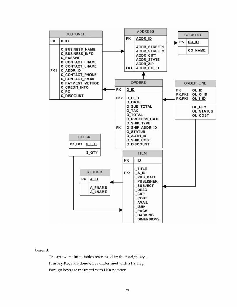
1.4 Database Entities, Relationships, and Characteristics
1.4.1 The components of the TPC-App database are defined to consist of a minimum of eight separate and individual base tables. The relationships among these tables are defined in the entity-relationship diagram shown below and are subject to the rules specified in clause 1.7.
Comment: To enable commercial products (commerce or merchant applications) to execute the workload without extensive modifications, a superset of the database schema is allowed subject constraints of clause 1.7 . This could be in the form of additional tables. All such additions and/or modifications MUST be fully disclosed.
27
Legend:
The arrows point to tables referenced by the foreign keys.
Primary Keys are denoted as underlined with a PK flag.
Foreign keys are indicated with FKn notation.
28
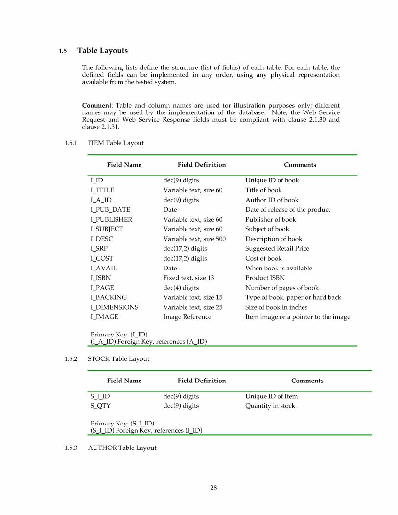
1.5 Table Layouts
The following lists define the structure (list of fields) of each table. For each table, the defined fields can be implemented in any order, using any physical representation available from the tested system.
Comment: Table and column names are used for illustration purposes only; different names may be used by the implementation of the database. Note, the Web Service Request and Web Service Response fields must be compliant with clause 2.1.30 and clause 2.1.31.
1.5.1 ITEM Table Layout
Field Name Field Definition Comments
I_ID dec(9) digits Unique ID of book I_TITLE Variable text, size 60 Title of book I_A_ID dec(9) digits Author ID of book I_PUB_DATE Date Date of release of the product I_PUBLISHER Variable text, size 60 Publisher of book I_SUBJECT Variable text, size 60 Subject of book I_DESC Variable text, size 500 Description of book I_SRP dec(17,2) digits Suggested Retail Price I_COST dec(17,2) digits Cost of book I_AVAIL Date When book is available I_ISBN Fixed text, size 13 Product ISBN I_PAGE dec(4) digits Number of pages of book I_BACKING Variable text, size 15 Type of book, paper or hard back I_DIMENSIONS Variable text, size 25 Size of book in inches I_IMAGE Image Reference Item image or a pointer to the image
Primary Key: (I_ID) (I_A_ID) Foreign Key, references (A_ID)
1.5.2 STOCK Table Layout
Field Name Field Definition Comments
S_I_ID dec(9) digits Unique ID of Item S_QTY dec(9) digits Quantity in stock
Primary Key: (S_I_ID) (S_I_ID) Foreign Key, references (I_ID)
1.5.3 AUTHOR Table Layout
29
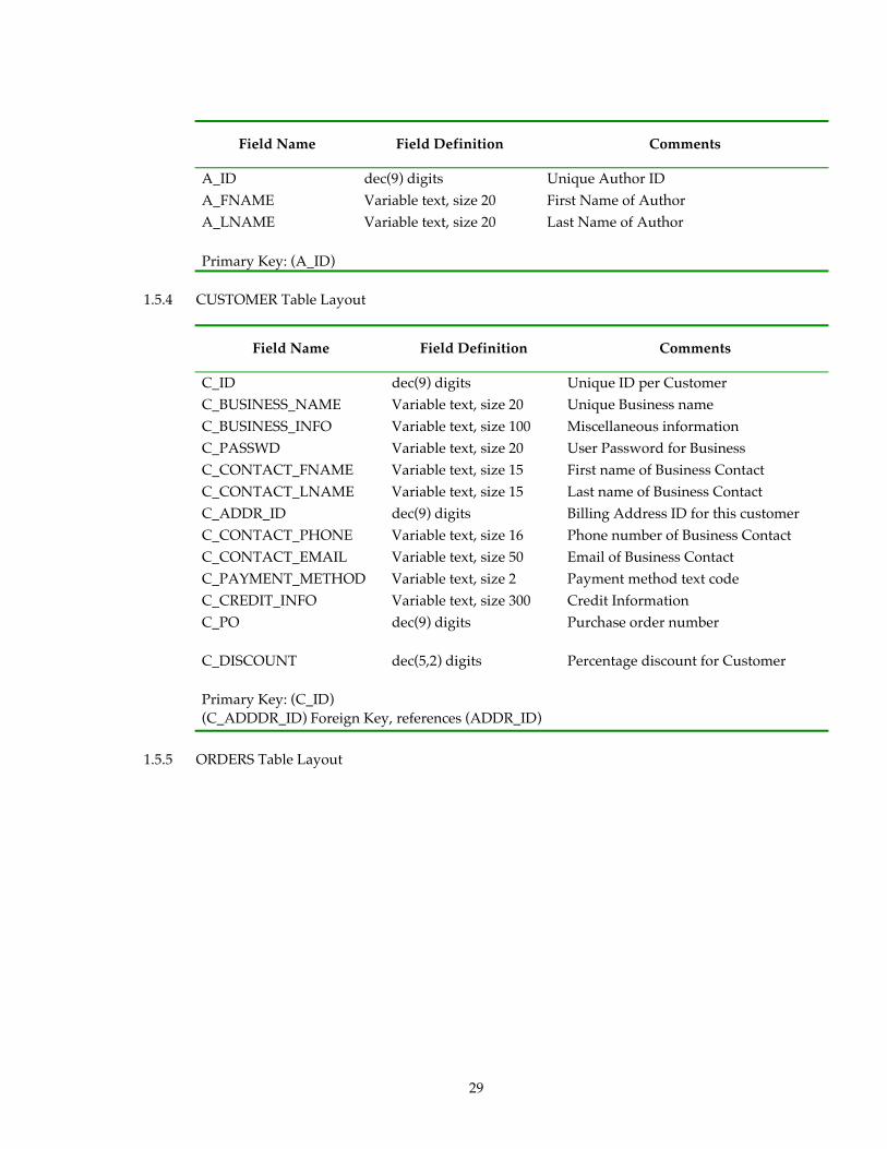
Field Name Field Definition Comments
A_ID dec(9) digits Unique Author ID A_FNAME Variable text, size 20 First Name of Author A_LNAME Variable text, size 20 Last Name of Author
Primary Key: (A_ID)
1.5.4 CUSTOMER Table Layout
Field Name Field Definition Comments
C_ID dec(9) digits Unique ID per Customer C_BUSINESS_NAME Variable text, size 20 Unique Business name C_BUSINESS_INFO Variable text, size 100 Miscellaneous information C_PASSWD Variable text, size 20 User Password for Business C_CONTACT_FNAME Variable text, size 15 First name of Business Contact C_CONTACT_LNAME Variable text, size 15 Last name of Business Contact C_ADDR_ID dec(9) digits Billing Address ID for this customer C_CONTACT_PHONE Variable text, size 16 Phone number of Business Contact C_CONTACT_EMAIL Variable text, size 50 Email of Business Contact C_PAYMENT_METHOD Variable text, size 2 Payment method text code C_CREDIT_INFO Variable text, size 300 Credit Information C_PO dec(9) digits Purchase order number
C_DISCOUNT dec(5,2) digits Percentage discount for Customer
Primary Key: (C_ID) (C_ADDDR_ID) Foreign Key, references (ADDR_ID)
1.5.5 ORDERS Table Layout

30
Field Name Field Definition Comments
O_ID dec(18) digits Unique ID per order O_C_ID dec(9) digits Customer ID of Order O_DATE Date and Time Order Date and Time O_SUB_TOTAL dec(17,2) digits Subtotal of all order-line items O_TAX dec(17,2) digits Tax over the subtotal O_TOTAL dec(17,2) digits Total for this order O_PROCESS_DATE Date and Time Date the orders was shipped to customer O_SHIP_TYPE Variable text, size 10 Method of delivery O_SHIP_ADDR_ID dec(9) digits Address ID to ship order O_STATUS Variable text, size 16 Order status O_AUTH_ID Variable text, size 16 Authorization code from PGE (for credit
orders) O_SHIP_COST dec(17,2) digits Shipping costs for this order O_DISCOUNT dec(5,2) digits Percentage discount off
Primary Key: (O_ID) (O_C_ID) Foreign Key, references (C_ID); (O_SHIP_ADDR) Foreign Key, references (ADDR_ID)
1.5.6 ORDER_LINE Table Layout
Field Name Field Definition Comments
OL_ID dec(3) digits Order Line Item ID (unique within this order)
OL_O_ID dec(18) digits Order ID of Order Line OL_I_ID dec(9) digits Unique Item ID (I_ID) OL_QTY dec(9) digits Quantity of items ordered OL_STATUS Variable text, size 16 Order Status for this item OL_I_COST dec(17,2) digits Cost for this item
Primary Key: (OL_ID, OL_O_ID) (OL_I_ID) Foreign Key, references (I_ID); (OL_O_ID) Foreign Key, references (O_ID)
1.5.7 ADDRESS Table Layout
31
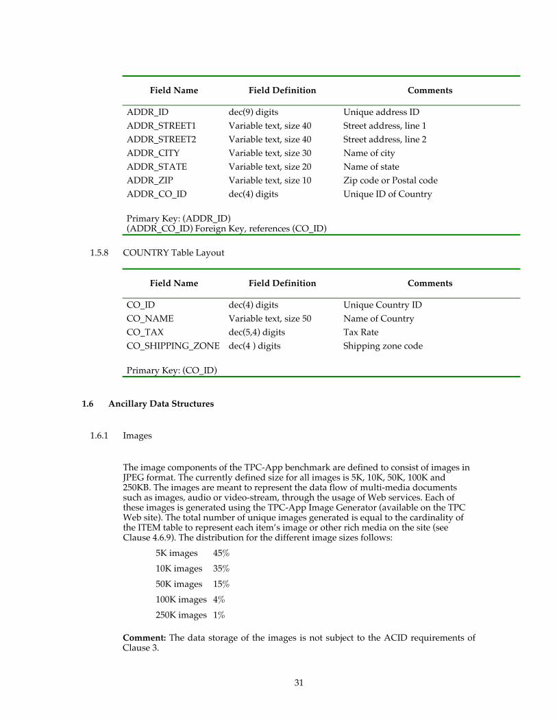
Field Name Field Definition Comments
ADDR_ID dec(9) digits Unique address ID ADDR_STREET1 Variable text, size 40 Street address, line 1 ADDR_STREET2 Variable text, size 40 Street address, line 2 ADDR_CITY Variable text, size 30 Name of city ADDR_STATE Variable text, size 20 Name of state ADDR_ZIP Variable text, size 10 Zip code or Postal code ADDR_CO_ID dec(4) digits Unique ID of Country
Primary Key: (ADDR_ID) (ADDR_CO_ID) Foreign Key, references (CO_ID)
1.5.8 COUNTRY Table Layout
Field Name Field Definition Comments
CO_ID dec(4) digits Unique Country ID CO_NAME Variable text, size 50 Name of Country CO_TAX dec(5,4) digits Tax Rate CO_SHIPPING_ZONE dec(4 ) digits Shipping zone code
Primary Key: (CO_ID)
1.6 Ancillary Data Structures
1.6.1 Images
The image components of the TPC-App benchmark are defined to consist of images in JPEG format. The currently defined size for all images is 5K, 10K, 50K, 100K and 250KB. The images are meant to represent the data flow of multi-media documents such as images, audio or video-stream, through the usage of Web services. Each of these images is generated using the TPC-App Image Generator (available on the TPC Web site). The total number of unique images generated is equal to the cardinality of the ITEM table to represent each item’s image or other rich media on the site (see Clause 4.6.9). The distribution for the different image sizes follows:
5K images 45%
10K images 35%
50K images 15%
100K images 4%
250K images 1%
Comment: The data storage of the images is not subject to the ACID requirements of Clause 3.
32
1.6.2 Shipping Cost Matrix
The Shipping Cost Matrix is used to calculate the shipping costs based on the total volume of the shipment and the shipping zone. The Shipping Cost Matrix contains the shipping costs (SHIP_COST) for various ranges of shipping volumes (SHIP_VOLUME) for a given country (SHIP_ZONE). All SHIP_VOLUMEs that could be generated during a Test Run are included in the Shipping Cost Matrix in .csv format on the TPC Web site. The SHIP_COST is determined for a given SHIP_ZONE by obtaining the associated SHIP_VOLUME that falls between the lower bound (inclusive) and the upper bound (exclusive) of the SHIP_VOLUME range delimiters. The format of this data structure can be rearranged into any form that suites the implementer, so long as the SHIP_COSTS and SHIP_ZONE refer to the data presented in the Shipping Cost Matrix.csv.
Comment 1: There are no ACID properties associated with this data structure. It MAY be stored and maintained in any way that is deemed appropriate by the implementer.
Comment 2: The storage or use of this data structure is not subject the the SUT restrictions of clause 6.5.3.
1.7 Database Implementation Rules
1.7.1 The physical clustering of records within the database is allowed.
1.7.2 The data fields described in clause 1.5 MUST be stored on a data repository that is durable and are subject to the ACID requirements of Clause 3 -.
1.7.3 All tables MUST have the properly scaled number of rows as defined by the database population REQUIREMENTS (see clause 4.3).
1.7.4 Horizontal partitioning of tables is allowed. Groups of rows from a table may be assigned to different files, disks, or areas. If implemented, the details of such partitioning MUST be disclosed.
1.7.5 Vertical partitioning of tables is allowed. Groups of fields (columns) of one table may be assigned to files, disks, or areas different from those storing the other fields of that table. If implemented, the details of such partitioning MUST be disclosed (see clause 1.9 for limitations).
1.7.6 Replication is allowed for all tables. Manipulation of data in all copies of tables that are replicated MUST meet all REQUIREMENTS for atomicity, consistency, and isolation as defined in Clause 3. If implemented, the details of such replication MUST be disclosed.
Comment: Only one copy of a replicated table needs to meet the durability REQUIREMENTS defined in Clause 3. (e.g., Non-durable replications MAY be refreshed from the durable data as necessary).
1.7.7 Fields MUST NOT be added or duplicated from one table defined in clause 1.5 into any of the other tables defined in clause 1.5. This does not preclude the use of views, temporary tables or permanent tables that do combine fields from multiple tables. However these are done, they MUST meet the Atomicity, Consistency, and Isolation REQUIREMENTS. The application MUST maintain the original tables as specified in clause 1.5.

33
1.7.8 Each field, as described in clause 1.5, MUST be logically discrete and independently accessible by the data manager and independently accessed by the application. For example, A_FNAME and A_LNAME MUST NOT be implemented as two sub-parts of a discrete attribute A_NAME.
1.7.9 Each field, as described in clause 1.5, MUST be accessible by the data manager, and accessed in the application as a single field. For example, C_BUSINESS_INFO MUST NOT be implemented as two discrete fields C_BUSINESS_INFO_1 and C_BUSINESS_INFO_2.
Comment: The following fields are exceptions to this clause: All fields holding a Date and Time value (i.e., O_DATE) MAY be implemented as a combination of two fields: a Date field and a Time field. Vertical partitioning MUST NOT be defined between the two fields used to implement Date and Time fields in this manner.
1.7.10 No field(s) may represent the physical disk addresses of the row or any offsets thereof. The application may not reference rows using relative addressing, i.e., simply offsets from the beginning of the storage space. This restriction does not preclude the use of hashing schemes or other file organizations that have provisions for adding, deleting, and modifying records in the ordinary course of processing.
Comment 1: It is the intent of this clause that the Application Program (see clause 1.2.22) executing the Transaction, or submitting the Transaction request, not use physical identifiers, but use logical identifiers for all accesses. Moreover, the Application Program MUST NOT translate or aid in the translation of a logical key to the location within the table of the associated row or rows. For example, it is not legitimate for the application to build a "translation table" of logical-to-physical addresses and use it to enhance performance.
Comment 2: Internal record or row identifiers, for example, tuple IDs or cursors, may be used under the condition that within each Transaction, initial access to any row MUST be via a logical key comprised only of fields from that row. Initial access includes insertion, deletion, retrieval, and update of any row.
1.7.11 While inserts and deletes are not performed on all tables, the system MUST NOT be configured to take special advantage of this fact during the test. Although inserts are inherently limited by the storage space available on the configured system, there MUST be no restriction on inserting in any of the tables a minimum number of rows equal to 5% of the table cardinality and with a key value of at least double the range of key values present in that table.
Comment: It is REQUIRED that the space for the additional 5% table cardinality be configured for the Test Run (see clause 5.4) and priced accordingly. If a commercial product is used for the application that REQUIRES a superset of the database schema, then the space configured and priced should include the additional storage needed for the additional tables and/or fields. For systems where space is configured and dynamically allocated at a later time, this space MUST be considered as allocated and included in the priced system (see clause 4.4).
1.7.12 The minimum decimal precision for any computation performed as part of the Application Program (see clause 1.2.22) MUST be the maximum decimal precision of all the individual items in that calculation. The application code MUST handle the entire range of values as defined in clause 1.5.
34
1.8 Integrity Rules
In any committed state, the primary key values MUST be unique within each table. For example, in the case of a horizontally partitioned table, primary key values of rows across all partitions MUST be unique.
1.9 Data Access Transparency REQUIREMENTS
Data access transparency is the property of the system that removes from the Application Program any knowledge of the location and access mechanisms of partitioned data. An implementation that uses vertical and/or horizontal partitioning MUST meet the REQUIREMENTS for transparent data access described here.
No finite series of tests can prove that the system supports complete data access transparency. The REQUIREMENTS below describe the minimum capabilities needed to establish that the system provides transparent data access.
Comment: The intent of this clause is to require that access to physically and/or logically partitioned data be provided directly and transparently by services implemented by Commercially Available layers below the Application Program such as the data/file manager (Database Server), the OPERATING SYSTEM, the hardware, or any combination of these.
1.9.1 All tables used by the application MUST be identified by names that have no relationship to the partitioning of tables. All data manipulation operations in the Application Program (see clause 1.2.22) MUST use only these names.
1.9.2 The system MUST prevent any data manipulation operation performed using the names described in clause 1.9.1 that would result in a violation of the integrity rules (see clause 1.8).
1.9.3 Using the names which satisfy clause 1.9.1, any arbitrary non-TPC-App application MUST be able to manipulate any set of rows or columns:
• Identifiable by any arbitrary condition supported by the underlying Database Server
• Using the names described in clause 1.9.1 and using the same data manipulation semantics and syntax for all tables.
For example, the semantics and syntax used to update an arbitrary set of rows in any one table MUST also be usable when updating another arbitrary set of rows in any other table.
Comment: The intent is that the TPC-App Application Program uses general-purpose mechanisms to manipulate data in the database.

35
Clause 2 - Web Service Interactions and Workload Profile
2.1 Implementation REQUIREMENTS
2.1.1 The use of Commercially Available products is mandated. The following functions, if used by the SUT, MUST be performed by Commercially Available products; the Application Program MUST NOT implement or directly reference these functions before or during the Test Run.
• OPERATING SYSTEM • Device drivers • Network • Multiplexing • Routing • Load Balancing • Caching (see clause 6.5.3)
2.1.2 If the SUT contains more than one SYSTEM, then the application server SYSTEM(s) MUST NOT contain the Database Server. This requirement does not apply if the publication is in either the Clustered-Virtualized or Non-Clustered-Virtualized categories.
2.1.3 The sending and receiving of Durable Messages as described in the Processing Definition for Create Order (clause 2.4.3.6.3) and the Shipping and Stock Management Processes (clauses 2.5.3 and 2.6.3), must use a commercially available Messaging Product (see clause 1.2.16).
2.1.4 The business logic defined outside of the delimiters <DBMS> and </DBMS> (See clause 1.2.59) define processing that MUST execute in the context of a Managed Environment..
2.1.5 APIs used to interface User Code with Commercially Available components of the SUT must be invoked from within the Managed Environment. The intent is that no non-managed intermediary code is used to invoke Commercially Available components of the SUT.
2.1.6 The following functions, if used by the SUT, MUST be provided by Commercially Available products:
• Distributed Transaction management (see clause 1.2.14) • Database (see clause 1.2.19) and libraries used to access database • Application Server (see clause 1.2.13) • Managed Environment (see clause 1.2.12) and “Post processing” byte code
optimizers • The use of the protocols discussed in clause 6.11.1 • Serialization, meaning in this specification:
o Converting application objects to the XML Infoset and back again (see clause 2.1.16)
o Converting SOAP messages into the XML Infoset and back again (see clauses 2.1.14 and 2.1.15)
• Communication, meaning in this specification: o Sending and receiving of SOAP messages o HTTP server and HTTP client functionality (see clause 2.1.21)
36
o SSL [SSL] / TLS [RFC 2246] encryption/decryption/handshake (see clause 2.1.23)
o Queue management (see clause 1.2.16) o The protocols discussed in clause 6.11
If the operation of these products are managed using, code, APIs or configuration files they MUST use general purpose facilities (i.e., not TPC-App benchmark specific). The Application Program MUST NOT implement any of the functions in the list above.
2.1.7 The Web Service Interactions that take place between the SUT and the RBE MUST be compliant with the [WS-I BP 1.0 Specification]. Additionally the Web Service Interactions that take place between the SUT and the external emulators (POV, ICE, PGE and SNE) MUST be compliant with the [WS-I BP 1.0 Specification]. All Web Service Interactions MUST pass the test for BP 1.0 compliance that is available on the WS-I Web site (http://www.ws-i.org). This test requires that all Web Service Requests and Web Service Responses pass through a proxy that captures the messages and writes them to a log file. There is a utility that then analyzes the log file and determines whether each Web Service Request is compliant with the [WS-I BP 1.0 Specification]. Since the tools supplied on the WS-I site do not currently support secure communications the security and encryption capabilities of the RBE, SUT and external emulators MUST NOT be in effect to be able to use the required testing tools. The steps for the test are as follows:
• Configure the SUT so that all Web Service Requests go through the proxy provided by the WS-I compliance test tool. This includes both the requests that go between the EB and the SUT and the requests that go between the SUT and the external emulators (POV, PGE, ICE and SNE).
• Configure the EB to initiate communications with the SUT using non-secure HTTP protocol.
• Configure the SUT to initiate communications with the external emulators (POV, PGE, ICE and SNE) using non-secure HTTP protocol.
• Start the RBE and run until at least one occurrence of each of the following: o Change Item o Product Detail o Order Status
An Order Status for a Customer that has placed an order An Order Status for a Customer that has not yet placed an order
o New Products o Change Payment Method o New Customer with a payment method of PO (POV) o Create Order (Stock Mgt, Shipping, PGE, ICE and SNE)
At least one back ordered item The C_ID MUST represent a customer that has a payment method of
credit card in the CUSTOMER table (C_PAYMENT_METHOD = CC), forcing a PGE test.
With a new Shipping Address information sent o Create Order with no change of address information (empty input field)
• Use the WS-I provided analysis tool to process the log file created by the above step. The results MUST be reported as described in clause 8.
Comment: It is permissible to modify the way that the RBE selects Web Service Interaction Types and inputs to expedite this test. The RBE is not REQUIRED to maintain the mix specified in clause 5 or the BSL specified in clause 6 during this test.

37
2.1.8 All SOAP messages comprising a Web Service Interaction MUST use secure HTTP (see clause 2.1.8) over TCP/IP as the communications protocol (See clause 6.11.1).
2.1.9 All communications between the Active EB and the SUT and between the SUT and the POV, PGE, ICE, and SNE MUST use secure HTTP. This means communications are encrypted and communicated with SSL version 3 [SSL] using SSL_RSA_WITH_RC4_128_MD5 as the cipher suite, or with TLS [RFC 2246] using TLS_RSA_WITH_RC4_128_MD5 as the cipher suite. The exception to this secure communication is during name resolution (e.g. DNS). The private key for the server digital certificate MUST be generated using a commercially available tool or API. The private key for the server digital certificate MUST be at least 1024 bits.
2.1.10 All Application Server SYSTEMS MUST be identical: The hardware configuration MUST be identical and be at the same firmware levels
• The Software configuration MUST be identical o The tunable parameters MUST be the same o Software used to initialize or manage the SUT MAY be different but
MUST only be used to initialize and manage the SUT. o The network address’ and computer names MAY be different
• All software components MUST be the same o The OPERATING SYSTEM MUST be the same o The patch levels MUST be the same for all software components o The device drivers MUST be the same
All Application Server SYSTEMS MUST process the same workload. The routing of a specific function (e.g., SSL/TLS, SOAP encoding, queue management, the routing of a Durable Message, etc) to specific Application Server SYSTEM(s) is not permitted. All Application Server SYSTEM(s) MUST be capable of handling all Web Service Interaction Types Comment 1: The intent of this clause is to prohibit specialized Application Servers. Any components not deployed across all SYSTEMs MAY only be used for initializing or managing the SUT. They MUST NOT perform any TPC-App related functions. Comment 2: A load balancing functionality is permitted to be performed on one or more Application Server SYSTEMS.
2.1.11 For each application server SYSTEM, the measured mix for each Web Service
Interaction Type MUST be within 5% of the required target (see clause 5.1). For example, for New Customer the allowed tolerance for any given application server SYSTEM is [0.95 .. 1.05]%.
2.1.12 The background processes of shipping and stock management must process messages at the same rate on all Application Server SYSTEMS. This REQUIREMENT MUST be met in one of two following ways.
1. The SUT is architected in such a way as to guarantee that all of the messages generated by Create Order on a given Application Server SYSTEM are processed on that SYSTEM. 2. The SUT is architected such that each Application Server SYSTEM measures the number of orders shipped on that SYSTEM. The method that is used to collect this data is up to the sponsor. The following relationship MUST hold for a Measurement Interval to be valid:
38
N1 = The highest number of orders shipped on any Application Server SYSTEM in the SUT
N2 = The lowest number of orders shipped on any Application Server SYSTEM in the SUT Comment: The measurement of the number of orders shipped on each Application Server SYSTEM could be done through an additional field in the ORDERS table to track which Application Server SYSTEM shipped the order.
2.1.13 For each Business Session, the Active EB associated with the Business Session MUST establish a new SSL/TLS session by executing a full handshake. SSL/TLS sessions MUST NOT be shared by multiple Business Sessions.
2.1.14 The SUT MUST parse all SOAP messages for the incoming Web Service Requests. The parser MUST be a Commercially Available component of the SUT.
2.1.15 The SOAP encoding for the Web Service Response MUST be handled by a Commercially Available component of the SUT.
2.1.16 A Commercially Available product MUST be used to serialize and deserialize all XML messages that are a part of the processing that takes place on the SUT. This consists of the following: • XML documents exchanged between the SUT and the RBE • XML documents exchanged between the SUT and the external emulators (PGE,
POV, ICE, and SNE). • XML documents exchanged between the Web Service Interactions and the
background processes (Shipping and Stock Management). These documents are sent as Durable Messages from one logical entity to another via the message queues (hosted by the Messaging Product) that are defined as part of the benchmark.
Comment: The intent is to avoid implementations where the Application Program implements XML serialization and/or de-serialization for these functions.
2.1.17 For any Web Service Interaction that returns an image, the image must be individually serialized into XML during generation of each Web Service Response. It is not permissible to return a pre-serialized image.
Comment: This REQUIREMENT applies only to a work performed on the SUT, and does not apply to the external emulators.
2.1.18 The SUT MUST manage all network connections between the SUT and external network endpoints by using Commercially Available components in the SUT. These connections MUST use TCP/IP (IPv4 or IPv6). See [RFC 791] and [RFC 2460].
2.1.19 If a DNS server is used, it must be part of the SUT and the EB MUST perform at least one DNS lookup per Business Session.
2.1.20 Application Code which performs queuing operations to the Shipping and Stock Management Processes is not allowed.
39
Comment: This does not preclude the use of Commercially Available APIs that interface with the Commercially Available Messaging Product. For instance, an API call that places a Durable Message on the Stock Management queue is permitted; however, Application Code that manages and handles the queue operations is not permitted.
2.1.21 The SUT MUST manage all HTTP communications between the SUT and external network endpoints by using a Commercially Available component on the SUT that provides a framework and/or APIs for managing HTTP functionality. This functionality includes, but is not limited to, listening for incoming HTTP connections, accepting and maintaining open sockets for these connections, receiving and parsing HTTP headers, sending response payloads and logging incoming HTTP requests in CLF format (see clause 2.1.32). If necessary, the Application Program may effect the creation and management of HTTP sessions and connections by using the APIs exposed by the Commercially Available HTTP layer directly.
In addition, opening outgoing HTTP connections, sending HTTP requests and payloads (e.g., send()) and receiving responses from external providers (e.g., PGE, etc.) MUST be performed by using a Commercially Available component(s) on the SUT that provides APIs for managing HTTP functionality.
Comment 1: The intent of this clause is to not explicitly require a separate product that provides the Web server functionality. This clause allows hosted applications to use APIs that hook to commercial functionality that provides needed HTTP functionality.
Comment 2: The Application Program MUST not explicitly open and utilize socket calls for incoming or outgoing HTTP requests. This low level functionality MUST be provided by Commercially Available components of the SUT.
2.1.22 If, in response to a Web Service Request, the SUT can not send a Web Service Response that meets the Output REQUIREMENTS of the Web Service Interaction, or the SUT can not perform all the business logic specified in the Processing Definition for the Web Service Interaction, then the SUT MUST send a Web Service Response that contains a SOAP fault that indicates this to the EB. Furthermore, this Web Service Response MUST conform to the SOAP Fault and HTTP Status requirements of the [WS-I BP 1.0 Specification].
2.1.23 The SUT MUST manage all SSL/TLS communications between the SUT and external network endpoints by using a Commercially Available product on the SUT that provides APIs for managing SSL/TLS functionality. This functionality includes, but is not limited to, SSL/TLS session establishment and resumption (handshaking), and encryption and decryption operations. The Application Program may effect the creation and management of SSL/TLS sessions and SSL/TLS connections by using these APIs directly.
2.1.24 The clauses titled Input REQUIREMENTS define the set of data REQUIRED by the SUT as input to the Web services. The underlying format for the WSDL documents is not mandated by this specification. Sample WSDLs are provided in Appendix E - .
Comment: This clause is not intended to allow an implementation to circumvent parsing overheads. The intent of this clause is to allow Web Services Integrated Development Environments to have flexibility in defining their own WSDL rather than mandating a specific WSDL.
2.1.25 The clauses titled Processing Definition define the business logic that MUST be executed by the SUT as part of the Web Service Interaction or process.

40
2.1.26 The order of the data manipulations within the Processing Definition bounds is immaterial, unless otherwise specified, and is left to the latitude of the test sponsor, as long as the implemented processes and Web Service Interactions are functionally equivalent to those specified in the Processing Definition.
2.1.27 The clauses titled Output REQUIREMENTS include a set of REQUIREMENTS for the Web Service Response produced by the SUT for that Web Service Interaction Type. A sample WSDL for the SOAP responses is found in Appendix E - .
2.1.28 If caching is used, it MUST meet all the REQUIREMENTS of clause 6.5.3.
2.1.29 Isolation level 2 is REQUIRED for all operations involving durable data (see clause 3.4.1).
2.1.30 While the XML schema is not defined for the Web Service Request and Web Service Response SOAP messages, the messages must use the field names defined in the Input REQUIREMENTS and Output REQUIREMENTS. Additionally the XML schema MUST use individual XML elements rather than attributes to delimit these fields.
Comment: The intent is to prohibit unrealistically small formats for the XML messages to gain performance advantages in serialization and deserialization.
2.1.31 The elements defined in the Input REQUIREMENTS and Output REQUIREMENTS must use the data types defined in the [W3C XML Schema Recommendation]. However, the following data types are not permitted for any fields other than I_IMAGE and SHIPLABEL_IMAGE:
• array of type Byte • hexBinary • base64Binary
Comment 1: The intent of limiting the element data types is to maintain consistent and realistic SOAP message size and prohibit message optimizations that a typical customer would not expect for the given Input and Output REQUIREMENTS (e.g., binary blobs). Comment 2: Message optimizations (e.g., user written compression or user written custom array encodings) MUST not be used for any SOAP messages communicated to or from the SUT.
2.1.32 The Web Server Access Log data MUST be collected continuously throughout the Test Run, use a minimum timestamp resolution of one second, and be written in Common Log Format [CLF] to persistent media. In addition to the requirements of Common Log Format, other fields may be added to each log record as desired.
2.1.33 The Change Item, Shipping, and Stock Management Web Service Interactions are administrative tasks. They are not components that a regular external business would see, but exist as part of the model depicted by the workload. Shipping and Stock Management do not require a Web service interface, since they are executing as background processes.
2.1.34 Each Active EB MUST use at least one independent random number stream (i.e., not shared with any other Active EB). See clause 6.4 for random number generator REQUIREMENTS. Each random number generator MUST be seeded with a unique value. Although the selection of the unique seeds is left to the implementer, it MUST NOT be done in a fashion that would improve performance. The start seeds MUST be selected in such a manner that they are not duplicates from previous Test Runs.

41
Comment: The intent is to avoid Active EBs following identical processing steps from previous runs that would result in any performance advantage (for example, resulting in a reduction of inserts to the ADDRESS table). While it is unreasonable to prove that the chosen start seeds were not used in any previous run, the auditor MUST verify that the seeding algorithm generates unique seeds for each run, and does not generate a similar set of seeds from any previous run since this database was initially populated.
2.1.35 The SUT is REQUIRED to generate random numbers for certain Web Service Interactions. If, for a particular Web Service Interaction, these random numbers are generated by multiple random number streams, the initial random number generator seeds MUST be unique from each other and across Test Runs. See clause 6.4 for random number generator REQUIREMENTS.
Comment: The intent of this clause is to prevent a performance advantage that could result from all the Active EBs or SUT systems using random numbers generated from a set of non-unique seeds which may generate non-random accesses and requests to the Web services and database objects. While it is unreasonable to prove that the chosen start seeds were not used in any previous run, the auditor SHOULD verify that the seeding algorithm generates unique seeds for each run, and does not generate a similar set of seeds from any previous runs since this database was initially populated.
2.1.36 If a data field defined in clause 1.5 is referenced more than once in a given Web Service Interaction, it is not REQUIRED to be obtained more than once from the Database Server.
2.1.37 The Current Date (see clause 1.3.11) for all SYSTEMs in the SUT MUST be synchronized to be within 1 second of each other throughout the duration of the Test Run.
Comment: The intent of this synchronization is to ensure consistent performance for Web Service Interactions using the Current Date to perform processing REQUIREMENTS, as well as consistency for reporting and auditing REQUIREMENTS.

42
2.2 New Customer Web Service
2.2.1 Overview
The New Customer Web Service Interaction accepts a Web Service Request for a new customer registration and returns the new customer ID (CUSTOMER_ID) to the Active EB.
2.2.2 Input REQUIREMENTS This Web Service Interaction is invoked by a Web Service Request and REQUIRES the
following input data:
• BUSINESS_NAME is a random a-string [15..20] • BUSINESS_INFO is a random a-string[40..100] • PASSWORD is generated as the value of BUSINESS_NAME in lowercase • CONTACT_F_NAME is a random a-string [8..15] • CONTACT_L_NAME is a random a-string [8..15] • CONTACT_PHONE is a random n-string [9..16] • CONTACT_EMAIL generated by the concatenation of the corresponding value of
CONTACT_F_NAME followed by the special character “@”followed by BUSINESS_NAME followed by the string of characters “.com”.
• PAYMENT_METHOD is chosen as either the string “PO” or “CC” as defined in clause 4.6.9. The percentage of New Customer Web Service Interactions containing a PAYMENT_METHOD of “PO”, measured during the Measurement Interval, MUST fall in the inclusive interval [48% , 52%].
• PO_ID is randomly selected within [1..1000000] • CREDIT_INFO is a random a-string [40..300] • BILLING_ADDR1 is a random a-string [15..40] • BILLING_ADDR2 is a random a-string [15..40] • BILLING_CITY is a random a-string [4..30] • BILLING_STATE is a random a-string [2..20] • BILLING_ZIP is a random a-string [5..10] • BILLING_COUNTRY is chosen according to clause 4.6.5.
2.2.3 Processing Definition
2.2.3.1 If PAYMENT_METHOD is “PO”, the SUT initiates a Web Service Request to the POV validating the CREDIT_INFO. See clause 6.6 for details on POV requests.
The POV request is an XML/SOAP request containing the following fields: • BUSINESS_NAME • PO_ID
The POV will return a unique AUTH_ID upon successful processing of the POV Web Service Request (see clause 6.6). For ease of benchmarking purposes it can be assumed that all successful SOAP responses will be POV approvals. Further processing for this Web Service Interaction MUST NOT proceed until receipt of this response. If the POV Web service interaction does not succeed, the SUT MUST return a SOAP fault to the EB.

43
2.2.3.2 <DBMS> <Start Database Transaction>
The SUT attempts to match the customer’s billing address (BILLING_STREET1, BILLING_STREET2, BILLING_CITY, BILLING_STATE, BILLING_ZIP, BILLING_COUNTRY) with an address in the ADDRESS table. If a match is found, then ADDR_ID_TEMP is set to ADDR_ID for the matching record. If no match is found, a new record is created in the ADDRESS table using the customer’s address with a new unique ADDR_ID (not necessarily sequential or contiguous) and ADDR_ID_TEMP is set to this new value.
Comment: The ADDR_CO_ID is obtained by comparing the BILLING_COUNTRY to the CO_NAME value in the COUNTRY table.
2.2.3.3 Insert the following information into the CUSTOMER table. • C_ID = The SUT will generate a unique C_ID for the new customer • C_BUSINESS_NAME = BUSINESS_NAME • C_BUSINESS_INFO = BUSINESS_INFO • C_PASSWD = PASSWORD • C_CONTACT_FNAME = CONTACT_FNAME • C_CONTACT_LNAME = CONTACT_LNAME • C_ADDR_ID = ADDR_ID_TEMP • C_CONTACT_PHONE = PHONE • C_CONTACT_EMAIL = EMAIL • C_PAYMENT_METHOD = PAYMENT_METHOD • C_CREDIT_INFO = CREDIT_INFO • C_PO = PO_ID • C_DISCOUNT generated as uniform [0.00 .. 50.00] <End Database Transaction> </DBMS>
2.2.4 Output REQUIREMENTS The SUT returns the following information to the Active EB in a Web Service Response: • SYSTEM_IDENTIFIER • CUSTOMER_ID (with the value of the new C_ID from clause 2.2.3.3)
44
2.3 Change Payment Method Web Service
2.3.1 Overview
The Change Payment Web Service Interaction allows the customer to request a change in method of payment.
Comment 1: For ease of benchmarking purposes, the Active EB will randomly choose the new payment method. The Active EB will choose “PO” 50% of the time, and “CC” 50% of the time. There is no requirement for the Active EB to have knowledge of the current customer payment method.
2.3.2 Input REQUIREMENTS
This Web Service Interaction is invoked by a Web Service Request and REQUIRES the following input data:
• CUSTOMER_ID (as determined in clause 6.3) • PAYMENT_METHOD is chosen as either the string “PO” or “CC” as defined in
clause 4.6.10. The percentage of Change Payment Web Service Interactions containing a PAYMENT_METHOD of “PO”, measured during the Measurement Interval, MUST fall in the inclusive interval [48% , 52%].
• CREDIT_INFO is a random a-string [40..300] • PO_ID is randomly selected within [1..1000000]
2.3.3 Processing Definition
2.3.3.1 If PAYMENT_METHOD is “PO” :
<DBMS>
<Start Database Transaction>
Obtain the C_BUSINESS_NAME for the given C_ID.
<End Database Transaction>
</DBMS>
The SUT initiates a POV request using C_BUSINESS_NAME and PO_ID as input to the POV. See clause 6.6 for details on POV processing REQUIREMENTS. This is an XML/SOAP request with the following fields:
• C_BUSINESS_NAME • PO_ID

45
The POV will return a unique AUTH_ID upon successful processing of the POV Web Service Request. Further processing MUST proceed only upon receipt of this response. If the POV Web service interaction does not succeed, the SUT MUST return a SOAP fault to the EB.
2.3.3.2 <DBMS>
<Start Database Transaction> The SUT updates the following information for the given C_ID:
• C_PAYMENT_METHOD = PAYMENT_METHOD • C_CREDIT_INFO = CREDIT_INFO • C_PO = PO_ID <End Database Transaction> </DBMS>
2.3.4 Output REQUIREMENTS
The SUT returns the following information to the Active EB in a Web Service Response: • SYSTEM_IDENTIFIER • CURR_PAYMENT_METHOD (with the value of C_PAYMENT_METHOD from
clause 2.3.3.2).

46
2.4 Create Order Web Service
2.4.1 Overview
The Create Order Web Service Interaction creates an order on the database and then notifies an order fulfillment system to ship the order.
2.4.2 Input REQUIREMENTS
This Web Service Interaction is invoked by a Web Service Request and REQUIRES the following input data:
• CUSTOMER_ID = C_ID where C_ID is selected as defined in clause 6.3 • Shipping address generated as defined in clause 2.4.2.7 • A list of item pairs (ITEM_ID, QTY) for all items to be purchased.
o The length of the item pair list is determined as defined in clause 2.4.2.1. o The values for ITEM_ID are selected as defined in clause 2.4.2.2 . o The values for the QTYs are selected as defined in clause 2.4.2.3
• SHIPPING_TYPE is generated as defined in clause 4.6.11 • CC_TYPE is selected as defined in clause 2.4.2.5 • CC_NUMBER is a random n-string[16..16] • CC_EXPIRY in ISO8601 format to adhere to XML standards is selected as defined in
clause 2.4.2.6 • CC_NAME is random a-string [10…30]
2.4.2.1 Selection of the length of the item pair list (ITEM_ID, QTY)
The length of the list of item pairs (ITEM_ID, QTY) is randomly selected within [1..MaxCreateOrderIDs]. See clause 1.2.70.
2.4.2.2 Selection of input item id (ITEM_ID)
Each ITEM_ID is randomly selected within [1..NUM_ITEMS]. For each Create Order Web Service Request, the list of chosen ITEM I_IDs MUST contain no duplicates. Comment: The input ITEM_I_IDs MUST NOT be sorted in order by the RBE. The intent of this comment is to prevent only updating a subset of rows as BACK_ORDERED items in the database.
2.4.2.3 Selection of input item quantities (QTY)
All QTY values are randomly selected within [1.. 10] with the following exception. For 10.0% of Create Order Web Service Interactions, one, and only one element of the list of item/qty pairs MUST have QTY set to 40. QTY set to 40 indicates that this single item is BACK_ORDERED.

47
The determination of whether a Create Order Web Service Interaction contains a BACK_ORDERED item MUST be made using the discrete distribution (0.1, 0.9), where 0.1 is the probability for containing a BACK_ORDERED item. The percentage of Create Order Web Service Interactions containing a BACK_ORDERED item, measured during the Measurement Interval, MUST fall in the inclusive interval [9.8% , 10.2%].
2.4.2.4 Selection of input country (COUNTRY_NAME) Selected with a random uniform distribution from the table specified in clause 4.6.5
2.4.2.5 Selection of input credit card type (CC_TYPE) Selected as a string with a random uniform distribution from the following list:
• VISA • MASTERCARD • DISCOVER • AMERICAN EXPRESS • DINERS CLUB
2.4.2.6 Selection of input credit card expiration date (CC_EXPIRY) Selected with a random uniform distribution over the following inclusive interval of dates: [Current Date+30 days...Current Date+1080 days]
2.4.2.7 Generation of Shipping Address
A new shipping address will be generated for 5% of the requests to create order. The determination of whether a Create Order Web Service Interaction request contains a new shipping address MUST be made using the discrete random distribution p(New Shipping Address) = 0.05, p(no New Shipping Address) = 0.95. The percentage of Create Order Web Service Interactions containing a new shipping address, measured during the Measurement Interval, MUST fall in the inclusive interval [4.9% , 5.1%].
If a new shipping address is not generated, either these inputs fields are populated with NULL values, or the section of the XML for these fields is omitted from the request, at the option of the vendor.
A new shipping address is generated by setting the following input fields as follows:
o SHIPPING_STREET1 is a random a-string [15..40] o SHIPPING_STREET2 is a random a-string [15..40] o SHIPPING_CITY is a random a-string [4..30] o SHIPPING_STATE is a random a-string [2..20] o SHIPPING_ZIP is a random a-string [5..10] o SHIPPING_COUNTRY is selected as defined in clause 2.4.2.4
2.4.3 Processing Definition
2.4.3.1 Validation 2.4.3.1.1 Determine payment method and if necessary invoke the PGE Web service.
<DBMS>
48
<Start Database Transaction> Obtain the C_PAYMENT_METHOD (current payment method, “PO” or “CC”) for this customer using C_ID = CUSTOMER_ID
<End Database Transaction> </DBMS>
If the C_PAYMENT_METHOD is “CC” (credit card) then the PGE (see clause 6.7) Web service is invoked to validate the credit card. This is an XML/SOAP request with the following fields:
• CC_NUMBER • CC_EXPIRY in ISO8601 format to adhere to XML standards • CC_NAME The PGE will return a unique AUTH_ID (authorization code) upon successful processing of the PGE Web Service Request. Further processing MUST proceed only upon receipt of this response. If the interaction with the PGE does not succeed (see clause 6.7) , the SUT MUST return a SOAP fault to the EB.
2.4.3.2 Insert new ADDRESS if necessary
<DBMS> <Start Database Transaction>
• If shipping address information is provided in the input for this Web Service Request and that shipping address does not already exist in the address table then a new unique ADDR_ID MUST be created and a record containing the shipping address information MUST be added to the ADDRESS table. Set ADDR_TEMP = the new ADDR_ID.
Comment 1: The ADDR_CO_ID is obtained by comparing the SHIPPING_COUNTRY_to the CO_NAME value in the COUNTRY table.
• If the address information provided already exists, the corresponding ADDR_ID
MUST be obtained. Set ADDR_TEMP = the existing ADDR_ID. • If no address information is provided, the current C_ADDR_ID for this customer
(where C_ID = CUSTOMER_ID) is used. Set ADDR_TEMP = C_ADDR_ID. • If no new address was submitted in the request, obtain the following values from
the ADDRESS and COUNTRY table where C_ID = ADDR_C_ID: SHIPPING_STREET1 = ADDR_STREET1 SHIPPING_STREET2 = ADDR_STREET2 SHIPPING_CITY = ADDR_CITY SHIPPING_STATE = ADDR_STATE SHIPPING_ZIP = ADDR_ZIP SHIPPING_COUNTRY = CO_NAME (using ADDR_CO_ID)
• Obtain the following information from the COUNTRY table where CO_ID = ADDR_CO_ID : TAX_RATE = CO_TAX SHIPPING_ZONE = CO_SHIPPING_ZONE
Comment 2: This portion of the Processing Definition is intentionally left out of the following Distributed Transaction (beginning in clause 2.4.3.3 )
49
<End Database Transaction>
</DBMS>
2.4.3.3 Calculate the costs of the order <Start Distributed Transaction> <DBMS>
2.4.3.3.1 Obtain the value of C_DISCOUNT from the CUSTOMER table where C_ID = CUSTOMER_ID for the given customer.
2.4.3.3.2 For each ITEM_ID contained in the input request obtain the value of I_COST and the item dimension data from the database where ITEM_ID = I_ID. The item dimension data MUST be either I_DIMENSION or the associated pregenerated item volume (see clause 2.4.3.3.3).
2.4.3.3.3 Calculate the following values: • SUB_TOTAL = (sum across all items in this order (I_COST * QTY)) * (1-
C_DISCOUNT/100) • TAX = TAX_RATE * SUB_TOTAL • SHIP_VOLUME = sum of all volumes for all items in this order where the item
volume (length * width * height * QTY) MUST be calculated using either I_DIMENSION or an additional pregenerated volume field (implementation dependent) for each item in the order. The pregenerated volume MUST match the volume represented in the DIMENSION field from the initial database population.
• SHIP_COST = The value in the Shipping Cost Matrix where the SHIP_VOLUME is in the volume range for the given SHIP_ZONE.
• TOTAL = SUB_TOTAL + TAX + SHIP_COST
2.4.3.4 Determine whether the order can be satisfied with existing stock. For each line item in the order that was received as input:
• Obtain the value of S_QTY from the STOCK table in the database where I_ID = ITEM_ID for this line item
• If S_QTY is greater than or equal to the QTY for this line item then set OL_STATUS_TEMP to PENDING for this line item
• If S_QTY is less than QTY for this line item then set OL_STATUS_TEMP to BACK_ORDERED
2.4.3.5 If any OL_STATUS field for this order was set to BACK_ORDERED then set O_STATUS_TEMP to BACK_ORDERED otherwise set O_STATUS_TEMP to “PENDING”
2.4.3.6 Create the Order on the database
2.4.3.6.1 A record is added to the ORDERS table with:
• O_ID is set to a new and unique order number. • O_C_ID is set to C_ID • O_DATE is set to the current OPERATING SYSTEM time and date of the
application server SYSTEM • O_SUB_TOTAL = SUB_TOTAL • O_TAX = TAX

50
• O_TOTAL = TOTAL • O_PROCESS_DATE is set to ’01/01/1800’ • O_SHIP_COST = SHIP_COST • O_SHIP_TYPE = Shipping Type from the input request • O_SHIP_ADDR_ID is set to ADDR_TEMP • O_AUTH_ID = AUTH_ID or “PO” if this is a purchase order Transaction. • O_DISCOUNT is set to C_DISCOUNT • O_STATUS is set to O_STATUS_TEMP
2.4.3.6.2 For each ITEM_ID in the input request insert a new record into the ORDER_LINE table with: • OL_ID is unique within the ORDER_LINE records for the order (not necessarily
sequential or contiguous) • OL_O_ID is set to O_ID • OL_I_ID is set to the ITEM_ID of the item in the input request • OL_QTY is set to QTY of the item in the input request • OL_I_COST is set to the current value of I_COST for this item • OL_STATUS is set to the value from clause 2.4.3.4 </DBMS>
2.4.3.6.3 Queue a single Durable Message in XML format to the SHIPPING queue (see clause 2.5.2) with the following information: • SHIPPING_O_ID = O_ID • SHIPPING_REQUEST_TIME = O_DATE in IS08601 format to adhere with XML
standards • SHIPPING_STATUS = O_STATUS • SHIPPING_STREET1 • SHIPPING_STREET2 • SHIPPING_CITY • SHIPPING_STATE • SHIPPING_ZIP • SHIPPING_COUNTRY
Comment: Structure of the XML message is up to the implementer. The only requirement is that it is a well formed XML 1.0 or greater document.
<End Distributed Transaction>
2.4.4 Output REQUIREMENTS The SUT returns the following information to the Active EB in a Web Service Response: • SYSTEM_IDENTIFIER • ORDER_ID (with the value of O_ID) • ORDER_STATUS (with the value of O_STATUS) • ORDER_TOTAL (with the value of O_TOTAL) • ORDER_TAX (with the value of O_TAX) • ORDER_SHIP_COST (with the value of O_SHIP_COST) • ORDER_DISCOUNT (with the value of C_DISCOUNT) • For each orderline in the order:
o ITEM_ID (with the value of OL_I_ID) o ITEM_QTY (with the value of OL_QTY) o ITEM_COST (with the value of OL_I_COST) o ITEM_STATUS (with the value of OL_STATUS)
A sample WSDL can be found in Appendix E -
51
2.5 Shipping Process
2.5.1 Overview The Shipping Process handles Durable Messages sent from the Create Order Web Service Interaction and the Stock Management Process via the Shipping queue. It performs the REQUIRED shipping business logic. For orders where sufficient stock exists to ship (flagged as PENDING), the order is updated to indicate that it has been shipped. Additionally a shipping label is obtained from the Shipment Notification Emulator (SNE). For orders that are flagged as BACK_ORDERED, a Durable Message is sent to the STOCK_MANAGEMENT queue indicating a restock is necessary.
2.5.2 Input REQUIREMENTS
The input MUST come in the form of an XML document that was enqueued by a single Create Order Web Service Interaction or from the processing of a Stock Management queue item, and is retrieved from the SHIPPING queue. This document contains the following information (see clause 2.4.3.6.3 for details on these input values):: • SHIPPING_O_ID = O_ID • SHIPPING_REQUEST_TIME = O_DATE in IS08601 format to adhere with XML
standards • SHIPPING_STATUS = O_STATUS • SHIPPING_STREET1 • SHIPPING_STREET2 • SHIPPING_CITY • SHIPPING_STATE • SHIPPING_ZIP • SHIPPING_COUNTRY
2.5.3 Processing Definition For the following Distributed Transaction, if at any point during the following steps an error occurs, the operation MUST be rolled back and processing restarted at clause 2.5.3.
2.5.3.1 <Start Distributed Transaction>
The SUT will continue to remove Durable Messages from the SHIPPING queue as they arrive throughout the Measurement Interval. When a message is received the business logic in clauses 2.5.3.2 through 2.5.3.4 MUST be executed.
2.5.3.2 <DBMS>
If the SHIPPING_STATUS is PENDING then the order process date (O_PROCESS_DATE) is set to the Current Date of the application server SYSTEM and the order status (O_STATUS) is set to SHIPPED. </DBMS>
The SUT sends a SOAP/XML request to the external Shipment Notification Emulator (SNE) Web service as defined in clause 6.9 with the following information:
• SHIPPING_STREET1 • SHIPPING_STREET2
52
• SHIPPING_CITY • SHIPPING_STATE • SHIPPING_ZIP • SHIPPING_COUNTRY
The SNE will return a TRACKING_NUMBER and SHIPLABEL_IMAGE upon successful processing of the SNE Web Service Request. The SUT is REQUIRED to fully deserialize each SNE Web Service Response. Further processing MUST proceed only upon full deserialization of this Web Service Response.
If the interaction with the SNE fails, a rollback occurs. Otherwise, the SOAP response MUST then be received. If the response is received without error then this Transaction is committed; otherwise this Transaction is rolled-back.
Comment: A typical business process would now generate a picking slip and print the SHIPLABEL_IMAGE received from the shipping vendor (FEDEX etc) for the warehouse to finish order fulfillment. That part of the business process is considered to be beyond the scope of this benchmark.
2.5.3.3 If the SHIPPING_STATUS is BACK_ORDERED: <DBMS> Queue a single Durable Message in XML format to the Stock Management queue containing:
• SHIPPING_REQUEST_TIME = O_DATE in ISO8601 format to adhere with XML standards
• SHIPPING_O_ID = O_ID • The REORDER_I_ID = OL_I_ID for the order line with a status of
BACK_ORDERED • The REORDER_QTY = OL_QTY for the order line with a status of
BACK_ORDERED • SHIPPING_STREET1 • SHIPPING_STREET2 • SHIPPING_CITY • SHIPPING_STATE • SHIPPING_ZIP • SHIPPING_COUNTRY
</DBMS>
2.5.3.4 <End Distributed Transaction>
2.5.3.5 The business logic defined within clauses 2.5.3.1 through 2.5.3.4 MUST iterate throughout the Test Run by going back to clause 2.5.3 and processing another Durable Message from the Shipping queue. Multiple orders MUST NOT be combined and processed into a single iteration.
Comment: The operation of removing the Durable Message from the queue and the database updates MUST be atomic. Typically, coordination of these operations would be performed by Transaction management software. The Transaction manager MAY have to be able to handle multiple resources, such as message queues and database updates. This process is typically known as a two-phase commit.
2.5.4 Output REQUIREMENTS None.
53
2.6 Stock Management Process
2.6.1 Overview The Stock Management Process handles Durable Messages sent from the Shipping
Process via the Stock Management queue. It performs the REQUIRED stock management business logic.
2.6.2 Input REQUIREMENTS
The input comes in the form of a Durable Message (in XML format) that is retrieved from the Stock Management queue. This Durable Message was placed on the queue via the Shipping Process and contains the following information (see clause 2.5.3.3 for details on these input values):
• The SHIPPING_O_ID = O_ID that is associated with this reorder request. • The SHIPPING_REQUEST_TIME = O_DATE in ISO8601 format to adhere with XML
standards • The REORDER_I_ID • The REORDER_QTY • SHIPPING_STREET1 • SHIPPING_STREET2 • SHIPPING_CITY • SHIPPING_STATE • SHIPPING_ZIP • SHIPPING_COUNTRY
2.6.3 Processing Definition
For the following Transaction, if at any point during the following steps an error occurs, the Transaction MUST be immediately rolled back, and ICE_STATUS set to ROLLBACK. Processing MUST then continue at clause 2.6.3. Note that it is assumed that the Transaction will never fail due to an invalid message.
<Start Distributed Transaction>
2.6.3.1 The SUT MUST continue to remove Durable Messages from the STOCK_MANAGEMENT queue as they arrive throughout the Test Run. When a Durable Message is received the business logic in clauses 2.6.3.2 through 2.6.3.4 MUST be executed. If the de-queue operation fails the Transaction MUST roll back (meaning the Durable Message MUST NOT be lost).
2.6.3.2 The SUT sends a SOAP/XML request to the external vendor Web service as defined in clause 6.8 (ICE) with the following information:
• Item ID (REORDER_I_ID) • Item Reorder Quantity (REORDER_QTY) • Order ID (SHIPPING_O_ID).
If the interaction with the ICE fails, a rollback occurs. Otherwise, the SOAP response MUST then be received. If the response indicates success then this Transaction is committed; otherwise this Transaction is rolled-back.

54
Comment 1: The rollback logic MAY be initiated with, but MUST NOT be implemented by the Application Program (e.g., re-insertion of records into the queue is not permitted).
Comment 2: Although the Web service interaction with the ICE is performed inside the Transaction, the ICE itself is not enlisted in the Transaction. At the time that this version of the specification was developed, Web services protocols were being developed to allow enlisting a remote Web service in an existing Transaction or executing compensating Transactions. However, these protocols were not yet widely available in commercial products therefore this specification does not require such protocols.
2.6.3.3 Queue a single Durable Message in XML format to the SHIPPING queue (see clause 2.1.2) with the following information: • SHIPPING_O_ID = O_ID • SHIPPING_REQUEST_TIME = O_DATE in IS08601 format to adhere with XML
standards • SHIPPING_STATUS = PENDING • SHIPPING_STREET1 • SHIPPING_STREET2 • SHIPPING_CITY • SHIPPING_STATE • SHIPPING_ZIP • SHIPPING_COUNTRY
Comment: The structure of the XML message is up to the implementer. The only requirement is that it is a well formed XML 1.0 or greater document.
<End Distributed Transaction>
2.6.3.4 <DBMS>
<Start Database Transaction>
Update the STOCK table setting S_QTY to a value that is randomly selected within [20 .. 30] where S_I_ID = the REORDER_ID.
Comment: See Appendix H - for an explanation on S_QTY updates.
<End Database Transaction> </DBMS> Comment: The update of the STOCK table step was intentionally left out of the previous Transaction. This processing would normally occur days later when the external vendor shipment is received. All typically required business logic for shipping and receiving from the external vendor are not included in the application for ease of benchmarking purposes. This update is included here to force updates to the stock table to prevent the table from being read-only.
2.6.3.5 The business logic defined above MUST be continually repeated throughout the Test Run by going back to clause 2.6.3 and processing another Durable Message from the STOCK_MANAGEMENT queue.
2.6.4 Output REQUIREMENTS None

55
2.7 Order Status Web Service
2.7.1 Overview
The Order Status Web Service Interaction returns information about the last n orders placed by the customer.
2.7.2 Input REQUIREMENTS This Web Service Interaction is invoked by a Web Service Request and REQUIRES the following input data: • CUSTOMER_ID = C_ID where C_ID is chosen according to clause 6.3 • ORDER_COUNT is randomly selected within [1..MAX_ORDERS]. See clause 1.2.64. • BUSINESS_NAME as defined in clause 4.6.1 if the Business Session has not
performed any New Customer Web Service Interactions. Otherwise, the BUSINESS_NAME from the last New Customer Web Service Interaction performed by the Business Session (see clause 6.3.4) is used.
• PASSWD either defined as in clause 4.6.2 if the Business Session has not performed any New Customer Web Service Interactions; or otherwise defined as the saved PASSWORD from the last New Customer Web Service Interaction performed by the Business Session (see clause 6.3.4).
2.7.3 Processing Definition
2.7.3.1 <DBMS>
<Start Database Transaction>
The SUT obtains the values for C_BUSINESS_NAME and C_PASSWD from the CUSTOMER table where C_ID = CUSTOMER_ID.
<End Database Transaction>
2.7.3.2 If the C_BUSINESS_NAME and C_PASSWD obtained matches the BUSINESS_NAME and PASSWD contained in the input request:
2.7.3.2.1 <Start Database Transaction> • The SUT obtains the following customer information for the given C_ID (where C_ID
= CUSTOMER_ID): • Customer first name (C_CONTACT_FNAME) • Customer last name (C_CONTACT_LNAME) • Customer phone number (C_CONTACT_PHONE) • Customer E-mail address (C_CONTACT_EMAIL) • Street address 1 (ADDR_STREET1) • Street address 2 (ADDR_STREET2) • City (ADDR_CITY) • State (ADDR_STATE) • Zip code (ADDR_ZIP) • Country name (CO_NAME)
2.7.3.2.2 The SUT obtains the following information for the last ORDER_COUNT orders for
this customer (using C_ID and O_DATE):
• Order ID (O_ID) • Order date (O_DATE) • Order subtotal (O_SUB_TOTAL)

56
• Order tax (O_TAX) • Order Total (O_TOTAL) • Order shipping type (O_SHIP_TYPE) • Order ship date (O_PROCESS_DATE) • Order status (O_STATUS) • Discount (O_DISCOUNT) • Order shipping cost (O_SHIP_COST) • Shipping address
o Street address 1 (ADDR_STREET1) o Street address 2 (ADDR_STREET2) o City (ADDR_CITY) o State (ADDR_STATE) o Zip code (ADDR_ZIP) o Country name (CO_NAME)
Comment: If fewer orders exist than are requested, the SUT will return all available orders for this customer.
<End Database Transaction>
2.7.3.2.3 For each item in each order the SUT obtains the following information
<Start Database Transaction> • Item ID (OL_I_ID) • Title (I_TITLE) • Publisher (I_PUBLISHER) • Cost (OL_I_COST) • Quantity (OL_QTY) • Status (OL_STATUS)
<End Database Transaction> </DBMS>
2.7.3.3 If the C_BUSINESS_NAME and C_PASSWD obtained do not match the BUSINESS_NAME and PASSWD contained in the input request the SUT returns a standard SOAP fault.
Note: This should not happen with the RBE but needs to be checked to ensure correct RBE functionality.
If there are no orders for the supplied C_ID, the customer info will be returned and the order info will be left empty.
2.7.4 Output REQUIREMENTS A sample WSDL can be found in Appendix E - . The SUT returns the following Order Status information to the Active EB in a Web Service Response: • SYSTEM_IDENTIFIER
2.7.4.1 The SUT returns the following customer information (obtained in clause Error! Reference source not found.) to the Active EB.
• CONTACT_FNAME (with the value of C_CONTACT_FNAME) • CONTACT_LNAME (with the value of C_CONTACT_LNAME) • CONTACT_PHONE (with the value of C_CONTACT_PHONE) • CONTACT_EMAIL (with the value of C_CONTACT_EMAIL) • BILLING_STREET1 (with the value of ADDR_STREET1) • BILLING_STREET2 (with the value of ADDR_STREET2)

57
• BILLING_CITY (with the value of ADDR_CITY) • BILLING_STATE (with the value of ADDR_STATE) • BILLING_ZIP (with the value of ADDR_ZIP) • BILLING_COUNTRY (with the value of CO_NAME)
2.7.4.2 For each order selected the SUT returns the following order information (obtained in clause 2.7.3.2.2) to the Active EB
• ORDER_ID (with the value of O_ID) • ORDER_DATE (with the value of O_DATE in ISO8601 format to adhere to XML
standards) • ORDER_SUB_TOTAL (with the value of O_SUB_TOTAL) • ORDER_TAX (with the value of O_TAX) • ORDER_TOTAL (with the value of O_TOTAL) • ORDER_SHIP_TYPE (with the value of O_SHIP_TYPE) • ORDER_PROCESS_DATE (with the value of O_PROCESS_DATE in ISO8601 format
to adhere to XML standards) • ORDER_STATUS (with the value of O_STATUS) • ORDER_SHIP_COST (with the value of O_SHIP_COST) • ORDER_DISCOUNT (with the value of O_DISCOUNT) • Shipping address
o SHIPPING_STREET1 (with the value of ADDR_STREET1) o SHIPPING_STREET2 (with the value of ADDR_STREET2) o SHIPPING_CITY (with the value of ADDR_CITY) o SHIPPING_STATE (with the value of ADDR_ STATE) o SHIPPING_ZIP (with the value of ADDR_ ZIP) o SHIPPING_COUNTRY (with the value of CO_NAME)
2.7.4.3 For each item in each order the SUT returns the following item information (obtained in clause 2.7.3.2.3) to the Active EB: • ITEM_ID (with the value of OL_I_ID) • ITEM_TITLE (with the value of I_TITLE) • ITEM_PUBLISHER (with the value of I_PUBLISHER) • ITEM_COST (with the value of OL_I_COST) • ITEM_QTY (with the value of OL_QTY) • STOCK_STATUS (with the value of OL_STATUS)
A sample WSDL can be found in Appendix E -
58
2.8 New Products Web Service
2.8.1 Overview
The New Products Web Service Interaction returns a list of recently modified items. The results for this Web Service Interaction will change throughout the Test Run, since the Change Item Web Service Interaction modifies I_PUB_DATE.
2.8.2 Input REQUIREMENTS
This Web Service Interaction is invoked by a Web Service Request and REQUIRES the following input data: • CUTOFF_DURATION is randomly selected within [1..10] minutes. • SUBJECT_STRING is used to filter the returned items by the subject. The Active EB
selects the subject string at random from the set of valid subjects (See clause 4.6.3) • ITEM_LIMIT is the maximum number of items to return. (See clause 1.2.67)
2.8.3 Processing Definition <DBMS>
<Start Database Transaction> The SUT obtains the I_ID, I_TITLE, A_FNAME, and A_LNAME for the first ITEM_LIMIT entries from the ITEM and AUTHOR tables where I_SUBJECT = SUBJECT_STRING and I_PUB_DATE > Current Date and Time of the application server SYSTEM minus CUTOFF_DURATION, sorted by descending I_PUB_DATE and ascending I_TITLE.
<End Database Transaction>
</DBMS>
2.8.4 Output REQUIREMENTS
The SUT returns the following information in a Web Service Response:
• SYSTEM_IDENTIFIER For each item obtained in clause 2.8.3 the SUT returns in the sorted order: • ITEM_ID (with the value of I_ID) • ITEM_TITLE (with the value of I_TITLE) • AUTHOR_FNAME (with the value of A_FNAME) • AUTHOR_LNAME (with the value of A_LNAME)
A sample WSDL can be found in Appendix E - .
59
2.9 Product Detail Web Service
2.9.1 Overview
The Product Detail Web Service Interaction returns detailed item information for a given set of requested items.
2.9.2 Input REQUIREMENTS
This Web Service Interaction is invoked by a Web Service Request and REQUIRES the following input data: • ITEM_ID list, which is a list containing 1 to MaxProductDetail_IDs I_ID values (See
clause 1.2.68). • The number of ITEM_IDs is randomly selected within [1 ..
MaxProductDetail_IDs] • The ITEM_ID values are chosen from the non-uniform random distribution
NURand(NURandAProductDetail, 1, NUM_ITEMS). See clause 1.2.69.
2.9.3 Processing Definition
<DBMS>
The SUT obtains the following information for each selected I_ID (where I_ID = ITEM_ID).
<Start Database Transaction> • I_ID • I_TITLE • A_FNAME • A_LNAME • I_PUB_DATE • I_PUBLISHER • I_SUBJECT • I_DESC • I_COST • I_SRP • I_AVAIL • I_ISBN • I_PAGE • I_BACKING • I_DIMENSIONS • I_IMAGE <End Database Transaction>
</DBMS>
2.9.4 Output REQUIREMENTS
The SUT returns the following to the Active EB in a Web Service Response:
60
• SYSTEM_IDENTIFIER
The detail information obtained in clause 2.9.3 for each of the requested I_IDs: • ITEM_ID (with the value of I_ID) • ITEM_TITLE (with the value of I_TITLE) • AUTHOR_FNAME (with the value of A_FNAME) • AUTHOR_LNAME (with the value of A_LNAME) • ITEM_PUB_DATE (with the value of I_PUB_DATE) • ITEM_PUBLISHER (with the value of I_PUBLISHER) • ITEM_SUBJECT (with the value of I_SUBJECT) • ITEM_DESC (with the value of I_DESC) • ITEM_COST (with the value of I_COST) • ITEM_SRP (with the value of I_SRP) • ITEM_AVAIL (with the value of I_AVAIL) • ITEM_ISBN (with the value of I_ISBN) • ITEM_PAGE (with the value of I_PAGE) • ITEM_BACKING (with the value of I_BACKING) • ITEM_DIMENSIONS (with the value of I_DIMENSIONS) • ITEM_IMAGE; the image JPG for this item, in serialized form
61
2.10 Change Item Web Service
2.10.1 Overview
The Change Item Web Services Interaction modifies the I_PUB_DATE for a set of items. Comment: For ease of benchmarking purposes, no items are actually added to the ITEM table during the Measurement Interval. However, the New Products Web Service Interaction will react to changes of the ITEM table by the Change Item Web Service Interactions as if they were functionally equivalent to item additions.
2.10.2 Input REQUIREMENTS
This Web Services Interaction is invoked by a Web Service Request and requires the following input data:
• ITEM_ID list, which is a list of 1 to MaxChangeItemIDs ITEM_ID values. The
number of ITEM_IDs is randomly selected within [1..MaxChangeItemIDs]. See clause 1.2.71.
• The ITEM_IDs contained in the ITEM_ID list are randomly selected within
[1..NUM_ITEMS]. The ITEM_IDs must be unique within the ITEM_ID list. If uniform random generation creates a duplicate ITEM_ID, iterate the selection until a unique ITEM_ID is chosen.
2.10.3 Processing Definition
<DBMS> For each of the submitted ITEM_IDs: <Start Database Transaction> Update the I_PUB_DATE value in the ITEM table, setting I_PUB_DATE =current Date and Time of the application server SYSTEM where I_ID = ITEM_ID. Select the I_PUB_DATE for this item where I_ID = ITEM_ID. <End Database Transaction>
</DBMS>
2.10.4 Output REQUIREMENTS
The SUT returns the following information to the Active EB in a Web Service Response:
• SYSTEM_IDENTIFIER • For each ITEM_ID in the ITEM_ID list, the SUT returns the following:
• ITEM_ID (with the value of I_ID) • ITEM_PUB_DATE (with the value of I_PUB_DATE) in ISO 8601 format
to adhere to XML standards as defined in clause 1.3.10
62
A sample WSDL can be found in Appendix E - .

63
Clause 3 - TRANSACTION AND SYSTEM PROPERTIES
Transaction ACID Properties
It is the intent of this section to define the ACID properties REQUIREMENTS for Web Service Interactions and to specify a series of tests that MUST be performed to demonstrate that these REQUIREMENTS are met.
3.1 Introduction
3.1.1 All processes interactions and Web Service Interactions with any database maintaining the tables defined in Clause 1 MUST be made through a Transaction supporting full ACID properties, as defined in clauses 3.2 through 3.5.
3.1.2 All processes and Web Service Interactions involving Durable Messages MUST handle the Durable Messages using a Commercially Available Messaging Product that supports full ACID properties. This Messaging Product MUST be a separate resource from the Database Server used to store durable data and MUST be accessed via standard messaging protocols and/or APIs.
3.1.3 No finite series of tests can prove that the ACID properties are fully supported. Passing the specified tests is a necessary, but not sufficient, condition for meeting the ACID REQUIREMENTS. However, for fairness of reporting, only the tests specified here are REQUIRED and the results of these tests MUST appear in the Full Disclosure Report for this benchmark.
Comment: These tests are intended to demonstrate that the ACID properties are supported by the SUT and enabled during the Test Run. They are not intended to be an exhaustive quality assurance test.
3.1.4 All mechanisms needed to insure full ACID properties MUST be enabled during both the ACID test period and the Test Run (as defined in clause 5.4). For example, if the SUT relies on undo logs, then logging MUST be enabled for all Transactions.
Although the ACID tests MAY not exercise all types of TPC-App Transactions, the ACID properties MUST be satisfied for all types.
3.1.5 To perform an Atomicity, Isolation, or Durability test, it is permissible to modify the Application Program or EB application as described for the steps in the given test.
3.1.6 Test sponsors reporting TPC-App results on a SUT containing two or more SYSTEMs MUST perform the Atomicity and Isolation tests on a single Application Server SYSTEM and also on each SYSTEM containing different TPC-App database tables. Consistency and Durability tests must be performed against the entire SUT as configured for the Test runs. If the benchmark utilizes more than one Messaging Product, it is necessary to perform the ACID tests on each Messaging Product. All Full Disclosure Reports MUST identify the SYSTEMs used to verify ACID REQUIREMENTS and full details of the ACID tests conducted and results obtained.
64
3.2 Atomicity
Atomicity Property Definition
The system under test MUST guarantee that Transactions are atomic. Within a Transaction the system will either perform all individual operations on the data, or will assure that no operations leave any effects on the data. Some of these atomicity tests MAY involve more than one resource manager. In these cases, the intent is to test the ‘all or nothing’ behavior of these Distributed Transactions.
3.2.1 Atomicity Tests
The atomicity tests require that the Create Order Web Service Interaction be instrumented so that the update to the database MAY be aborted while in progress, affecting the final outcome of the update, but without affecting the ability of the SUT to complete the Web Service Interaction. The following atomicity tests are completed without other Web Service Interactions in progress.
3.2.1.1 The following steps describe atomicity test 1:
Step 1. Request and complete a Create Order Web Service Interaction.
Step 2. Request and complete an Order Status Web Service Interaction for the same EB used in Step 1, using a value of 1 for NUM_ORDERS.
Step 3. The information presented in the SOAP response document from Step 2 MUST match the order entered in Step 1.
3.2.1.2 The following steps describe atomicity test 2:
Step 1. Request an Order Status for a given EB to view the last order committed for this customer.
Step 2. Disable all SHIPPING processes such that the queuing software is accepting Durable Messages but no Durable Messages are processed.
Step 3. Request a Create Order Web Service Interaction for the EB used in Step 1 with the same C_ID but different input data than Step 1. Rollback the Distributed Transaction after queuing the Durable Message to the Shipping Process.
Step 4. Request and complete an Order Status Web Service Interaction for the EB used in Step 1.
Step 5. The information presented in the SOAP response document from Step 4 MUST make no mention of the order entered in Step 3.
Step 6. The Durable Message queued in Step 3 MUST NOT reside on any Shipping queue.
3.2.1.3 The following steps describe the atomicity test 3:
Step 1. Ensure that all Stock Management queues are empty and that the Stock Magagement Process is disabled.
Step 2. Request a Create Order Web Service Interaction. The request MUST include one backorder request (I_QTY = 40), which enques a Shipping Durable Message. Note the O_ID returned in the Web Service Response.
65
Step 3. The Shipping Process on one Application Server SYSTEM MUST receive and process the new Durable Message. The processing MUST perform the REQUIRED updates on the database and send the backorder request to the Stock Management queue, but rollback the changes before committing the Transaction.
Step 4. Halt the processing of the shipping queue.
Step 5. View the Stock Management queue associated with the Shipping queue in Step 3. There MUST be no Durable Message on the queue with the O_ID from Step 2.
Step 6. View the SHIPPING queue examined in Step 3. It MUST contain the Shipping Durable Message with the O_ID from Step 2.
Step 7. Verify that the O_PROCESS_DATE for the order in step 2 is set to ‘1/1/1800’
3.2.1.4 The following steps describe atomicity test 4:
Step 1. Request a New Customer Web Service Interaction. The request MUST contain customer and address information that is not already in the ADDRESS or CUSTOMER table.
Step 2. Insert the customer and address data but rollback the Transaction instead of committing.
Step 3. Using a database query utility, verify that the database does not contain either the customer or address information inserted in Step 2.
3.3 Consistency
3.3.1 Consistency Property Definition
The system under test MUST guarantee that Transactions are consistent. Assuming that the database is initially in a consistent state, the system will ensure that any TPC-App Transaction takes the database from one consistent state to another.
Consistency Conditions
A consistent state for the TPC-App database is defined to exist when:
1. (I_A_ID) is a valid Foreign Key reference to an existing (A_ID)
2. (C_ADDR_ID) is a valid Foreign Key reference to an existing (ADDR_ID)
3. (O_C_ID) is a valid Foreign Key reference to an existing (C_ID)
4. (O_SHIP_ADDR) is a valid Foreign Key reference to an existing (ADDR_ID)
5. (OL_I_ID) is a valid Foreign Key reference to an existing (I_ID)
6. (OL_O_ID) is a valid Foreign Key reference to an existing (O_ID)
7. (ADDR_CO_ID) is a valid Foreign Key reference to an existing (CO_ID)
8. (S_I_ID) is a valid Foreign Key reference to an existing (I_ID)

66
9. All (O_STATUS) must be set to SHIPPED for all orders in the database. There MUST be no O_STATUS in the database with a value of PENDING or BACK_ORDERED. It is REQUIRED that the Shipping and Stock Management Queues be completely processed prior to executing the test for this condition.
3.3.2 A TPC-App database, when populated as defined in clause 4.7, MUST meet the consistency condition defined in clause 0.
3.3.3 If data is replicated, as permitted under clause 1.7.6, each copy MUST meet the consistency condition defined in clause 0.
3.3.4 The implementation of the Web Service Interactions MUST ensure that all consistency conditions defined in clause 0 are maintained without relying on a limited range of input data. However, the implementation of the benchmark is NOT REQUIRED to maintain these consistency conditions under arbitrary Transactions.
Comment: The above statement implies that no referential integrity is REQUIRED to be enforced at the database level.
3.3.5 Consistency Test
The verification of the consistency between the ORDERS and CUSTOMER tables (condition #3), between the ORDERS and ADDRESS tables (condition #4), between ORDER_LINE and ORDERS (condition #6), and between Shipping Process and the ORDERS table (condition #9) is performed after the Durability test(s) (see clause 3.5.4.1) and immediately after the Test Run (see clause 5.4.2).
Comment 1: For ease of benchmarking purposes, it is permissible to perform the above consistency verfication only once after both the Test Run and ACID tests have completed. However, this is only permissible if the database has not been restored at any point between executing the ACID tests and the Test Run.
Comment 2: While maintaining other consistency conditions defined in clause 3.3.2 is REQUIRED, their verification is left to the discretion of the auditor.
3.4 Isolation
3.4.1 Isolation Property Definition
Isolation can be defined in terms of phenomena that can occur during the execution of concurrent Transactions. The following phenomena are considered, given two atomic Transactions, T1 and T2:
P0 ("Dirty Write"): Transaction T1 reads a data element and modifies it. Transaction T2 then modifies or deletes that data element and performs a COMMIT. If T1 were to attempt to re-read the data element, it MAY receive the modified value from T2 or discover that the data element has been deleted.
P1 ("Dirty Read"): Transaction T1 modifies a data element. Transaction T2 then reads that data element before T1 performs a COMMIT. If T1 were to perform a ROLLBACK, T2 will have read a value that was never committed and that MAY thus be considered to have never existed.

67
P2 ("Non-repeatable Read"): Transaction T1 reads a data element. Transaction T2 then modifies or deletes that data element, and performs a COMMIT. If T1 were to attempt to re-read the data element, it MAY receive the modified value or discover that the data element has been deleted.
P3 ("Phantom"): Transaction T1 reads a set of values N that satisfy some <search condition>. Transaction T2 then executes statements that generate one or more data elements that satisfy the <search condition> used by Transaction T1. If Transaction T1 were to repeat the initial read with the same <search condition>, it MAY obtain a different set of values.
The following table defines four isolation levels with respect to the phenomena P0, P1, P2, and P3.
Isolation Level
P0 P1 P2 P3
0 Not Possible Possible Possible Possible 1 Not Possible Not Possible Possible Possible 2 Not Possible Not Possible Not Possible Possible 3 Not Possible Not Possible Not Possible Not Possible
The following Transactions are defined:
Tr = Any read-only Transaction used to implement a TPC-App Web Service Interaction
Tu = Any update Transaction used to implement a TPC-App Web Service Interaction
Tn = Any arbitrary Transaction (Although arbitrary, this Transaction MAY not do dirty writes)
Unless otherwise specified, the system under test MUST ensure that the isolation REQUIREMENTS defined in the table below are met by all Transactions. (See clause 2.1.29)
Req. #
For Transactions in this set:
these phenomena:
MUST NOT be seen by this Transaction:
Textual Description:
1. {Tu, Tn} P0, P1, P2 Tu Level 2 isolation for any TPC-App update Transactions relative to any arbitrary Transaction.
2. {Tr, Tn} P0, P1 Tn Level 1 isolation for any TPC-App read-only Transaction relative to any arbitrary Transaction.
3.4.2 Isolation Tests
The isolation tests require that several Web Service Interactions be modified so that a query or an update to the database MAY be halted while in progress, without affecting the final outcome of the query or the update, and without affecting the ability of the SUT to complete the Web Service Interaction. The following Isolation tests are completed without other Web Service Interactions in progress.
3.4.2.1 Isolation Test 1

68
To verify isolation between two TPC-App update Transactions, perform the following steps:
Step 1. From EB 1, perform a Product Detail Web Service Interaction for a given I_ID.
Step 2. From EB 1, perform a Change Item Web Service Interaction to modify the I_ID from Step 1.
Step 3. Interrupt the processing of the Change Item Web Service Interaction from EB 1 after updating the I_PUB_DATE, but before committing the update.
Step 4. From EB 2, request a Product Detail for the item from Step 1. Verify that the Product Detail Web Service Interaction either waits for EB 1 to resume or completes. If the Product Detail Web Service Interaction completes verify that the I_PUB_DATE returned is the original date from Step 1, not the date modified from Step 2.
Step 5. Resume the processing of the Change Item Web Service Interaction interrupted in Step 3.
Step 6. Verify that EB 1 receives a Change Item SOAP response containing the item’s new I_PUB_DATE.
Step 7. If the Product Detail did not already complete in Step 4, allow EB2 to continue processing. In this case the Product Detail response MUST reflect the new I_PUB_DATE.
3.4.2.2 Isolation Test 2
To verify isolation between a TPC-App update Transaction and an arbitrary Transaction, perform the following steps:
Step 1. Obtain the value of I_PUB_DATE for an item.
Step 2. From an EB, initiate a modified Change Item Web Service Interaction that updates the I_PUB_DATE to ‘8-8-1988’ for the item from Step 1.
Step 3. Interrupt the processing of the Change Item Web Service Interaction after updating the I_PUB_DATE, but before committing the change.
Step 4. Using a database update utility, request a Transactional update of the I_PUB_DATE of the item targeted by Step 1, setting it to ’1-1-1970’. Commit this update as soon as allowed by the database. The update request MAY hang waiting for the processing of the Change Item Web Service Interaction to complete.
Step 5. Resume the processing of the Change Item Web Service Interaction interrupted in Step 3.
Step 6. If the EB completes successfully verify that the EB receives a SOAP response containing the EB’s update to I_PUB_DATE (8-8-1988).
Step 7. If the database update completes successfully, query the database to verify that I_PUB_DATE contains 1-1-1970.
Step 8. If both the EB and the database query do not complete successfully, verify I_PUB_DATE contains the original value.
3.4.2.3 Isolation Test 3
69
To verify isolation between a TPC-App read-only Transaction and an arbitrary Transaction, perform the following steps:
Step 1. From an EB, request and complete an Order Status Web Service Interaction. Ensure that at least one order is returned.
Step 2. Using a database query and update utility, request a Transactional update of the quantity of the first line item of the first order returned in Step 1, but do not commit this update.
Step 3. From the same EB, request and complete another Order Status Web Service Interaction to obtain the same order as in Step 1
Step 4. Verify that the EB’s Order Status Web Service Interaction either waits for the update utility to commit or returns an Order Status Web Service Response containing the same information as displayed in Step 1.
Step 5. Using the database query and update utility, commit the pending update to the database.
Step 6. If the EB was waiting in Step 4, verify that it has resumed and that it receives an Order Status SOAP response containing the new quantity for the first line item. If the browser was not waiting in Step 4, request and complete a new Order Status Web Service Interaction to obtain the same order as in Step 1 and verify that the Order Status SOAP response contains the new quantity for the first line item.
Comment: The execution of this test can cause inconsistencies between the initial database population REQUIREMENTS and the database population (i.e., O_TOTAL and O_SUB_TOTAL). A database restore or a restore of the modified OL_QTY to a consistent value will be necessary for subsequent Test Runs.
3.4.2.4 Isolation Test 4
This test is only REQUIRED if de-queuing of the Shipping queue is multithreaded.
To verify isolation between Durable Messages removed from the Shipping queue:
Step 1. Ensure all Shipping queues are empty.
Step 2. Disable all Shipping process such that no Durable Messages in the Shipping queue are processed.
Step 3. Modify the Shipping process on the Application Server SYSTEM that will process the Shipping queue being tested such that the messages are removed from the queue and logged to a file by the application, followed by a delay of 120 seconds before the Transaction is committed.
Step 4. Configure or modify the SUT such that the Create Order Web Service Interactions can target a given Application Server SYSTEM and that the Application Server SYSTEM routes all Shipping queue entries to a single Shipping queue.
Step 5. Enable the Shipping process.
Step 6. From an EB, request and complete two successful Create Order Web Service Interactions that are performed on the same Application Server SYSTEM within 60 seconds of each other but no less than 10 seconds of each other.
70
Step 7. Verify in the Shipping process log that there are no duplicates of the messages from Step 6.
3.4.2.5 Isolation Test 5
This test is only REQUIRED if de-queuing of the Stock Management queue is multithreaded.
To verify isolation between messages removed from the Stock Management queue:
Step 1. Ensure that the Stock Management queue is empty.
Step 2. Disable the Stock Management Process such that no Stock Management queue messages are processed.
Step 3. Modify the Stock Management process such that the messages are removed from the queue and logged to a file by the application, followed by a delay of 120 seconds before the Transaction (beginning with clause 2.6.3.1) is committed.
Step 4. Configure or modify the SUT such that the Create Order Web Service Interactions can target a given Application Server SYSTEM and that the Application Server SYSTEM routes all Stock Management queue entries to a single Stock Management queue.
Step 5. Enable the Stock Management Process. Allow it to remove all items from the queue.
Step 6. From an EB, request and complete two successful Create Order Web Service Interactions targeting the same Application Server SYSTEM, each of which force one BACK_ORDERED item (OL_I_QTY = 40). These Web Service Requests MUST be initiated within 60 seconds of each other but no less than 10 seconds of each other.
Step 7. Verify that there are no duplicates of the messages in the file(s) from Step 3.
3.5 Durability
3.5.1 Durability Property Definition
The system under test MUST guarantee that Transactions are durable. The system will preserve the effects of any committed Transaction after recovery from any single point of failure.
Comment: No system provides complete durability (i.e., durability under all possible types of failures). The specific set of single failures addressed in clause 3.5.3 is deemed sufficiently significant to justify demonstration of durability across such failures. However, the limited nature of the tests listed MUST NOT be interpreted to allow other unrecoverable single points of failure.
3.5.2 Committed Transaction Definition
71
A Transaction is considered committed when the Transaction manager components of the system have either written the log or written the data for the committed updates associated with the Transaction to a durable medium.
Comment 1: Transactions can be committed without the user subsequently receiving notification of that fact, as the Web Service Interaction MAY fail after the Transaction has been committed.
Comment 2: For the processes and Web Service Interactions that require Distributed Transaction(s), the Distributed Transaction Manager MUST also meet the above REQUIREMENT to satisfy the Durable Message REQUIREMENTS.
3.5.3 List of Single Points of Failure
The Single Points of Failure apply to components of the SUT that contribute to the durability REQUIREMENT.
A single test can adequately satisfy the REQUIREMENTS of multiple single points of failure (e.g., A single "system crash test" could be used for the memory failure, system failure, and power failure REQUIREMENTS.)
3.5.3.1 Medium Failure: Permanent irrecoverable failure of any single durable medium active during any Measurement Interval.
Multiple concurrent failures do not need to be tested. For example, the database log disk subsystem can be assumed to provide redundancy to the database data disk subsystem. In this example, because of the implicit redundancy, testing loss of connectivity to the log subsystem is a sufficient test of both log and data disk subsystems.
If physical memory is used as a durable medium, then it MUST be considered as a potential single point of failure. Sample mechanisms to survive single durable medium failures are database archiving in conjunction with a redo (after image) log, and mirrored durable media. If memory is the durable medium and mirroring is the mechanism used to ensure durability, then the mirrored memories MUST be independently powered.
Comment: The durable medium which contains the OPERATING SYSTEM is subject to these durable Medium REQUIREMENTS.
3.5.3.2 Memory Failure: Failure of all or part of memory (loss of contents).
This implies that all or part of memory has failed. This MAY be caused by a loss of external power or the permanent failure of a board equipped with memory.
3.5.3.3 System Failure: Instantaneous interruption (SYSTEM crash/SYSTEM hang) in processing which causes all or part of the processing of atomic Transactions to halt.
This MAY imply abnormal SYSTEM shutdown which REQUIRES loading of a fresh copy of the OPERATING SYSTEM from the boot device. It does not necessarily imply loss of volatile memory. When the recovery mechanism relies on the pre-failure contents of volatile memory, the means used to avoid the loss of volatile memory (e.g., an Uninterruptible Power Supply) MUST be included in the Priced Configuration. A sample mechanism to survive an instantaneous interruption in processing is an undo/redo log.

72
In configurations where more than one SYSTEM participates in a Transaction and are connected via a medium other than an integrated bus (e.g., bus extender cable, high speed LAN, or other connection methods between the SYSTEMs that could be vulnerable to a loss from physical disruption), the instantaneous interruption of this communication is included in this definition as an item that needs to be tested. Interruption of one instance of redundant connections is REQUIRED.
Comment: It is not the intention of this clause to require interruption of communication to disk towers or a disk subsystem where redundancy exists. For example, if redundant host bus adapters and/or physical connection to a disk subsystem exists, only one communication path is REQUIRED to be interrupted.
3.5.3.4 SUT Power Failure: Loss of all external power to the SUT for an indefinite time period. This MUST include at least all portions of the SUT that participate in the Web Service Interactions.
Comment: The power failure REQUIREMENT MAY be satisfied by including sufficient UPSs to guarantee system availability of all components that fall under the power failure REQUIREMENT for a period of at least 30 minutes. Use of a UPS-protected configuration MUST NOT introduce new single points of failure that are not protected by other parts of the configuration. This REQUIREMENT MAY be proven either through a measurement or through a calculation of the 30-minute power REQUIREMENTS (in watt-hours) for the portion of the SUT that is protected multiplied by 1.4. The 30 minute power REQUIREMENT assumes that a graceful shutdown (as REQUIRED to meet the indefinite power loss REQUIREMENT) of the SUT component is possible within this timeframe.
This type of failure is sufficiently exercised by removing power from every system that contributes to satisfying the durability REQUIREMENT.
3.5.4 Durable Medium Definition
A durable medium is a data storage medium that is either:
1. An inherently non-volatile medium (e.g., magnetic disk, magnetic tape, optical disk, etc.) or
2. A volatile medium that will ensure the transfer of data automatically, before any data is lost, to an inherently non-volatile medium after the failure of external power independently of reapplication of external power. (A configured and priced Uninterruptible Power Supply (UPS) is not considered external power if redundant power capabilities are provided on the component.)
Comment: A durable medium can fail. Protection from failure is usually accomplished through replication on a second durable medium (e.g., mirroring) or logging to another durable medium. Memory can be considered a durable medium if it can preserve data long enough to satisfy the REQUIREMENT stated in item 2 above; for example, if it is accompanied by an Uninterruptible Power Supply, and the contents of memory can be transferred to an inherently non-volatile medium during the failure. Note that no distinction is made between main memory and memory performing similar permanent or temporary data storage in other parts of the system (e.g., disk controller caches).
3.5.4.1 Durability Tests
3.5.4.1.1 Durability Test for SUT Components
73
For each component susceptible to one of the failure types defined in clause 3.5.3 perform the following steps:
Step 1. Obtain the total number of rows in the ORDERS table to determine the current count of orders (order_count1) in the database.
Step 2. Disable the Shipping Processes and ensure that the Shipping queues are empty.
Step 3. Start the workload of Web Service Interactions using the same number of EBs used for the Test Run.
Step 4. Once all EBs have started requesting Web Service Interactions, run for at least 5 minutes and keep a count of the number of Create Order Web Service Interactions successfully completed by all EBs.
Step 5. Cause the failure selected from the list in clause 3.5.3.
Step 6. Stop the RBE and collect the total number of Create Order Web Service Interactions successfully completed by all EBs (RBE_order_count).
Step 7. If necessary, stop and restart the system under test using normal recovery procedures, where applicable.
Step 8. Repeat step 1 to determine the current count of orders (order_count2) in the database. Verify that (order_count2 - order_count1) is greater than or equal to the number of successfully completed Create Order Web Service Interactions (RBE-order_count). If there is an inequality, the difference MUST be less than or equal to the number of EBs active during this test.
Comment 1: This difference should be due only to Transactions that were committed on the system under test, but for which the SOAP response message was not returned to the EB before the failure.
Step 9. Obtain the the count of all messages on the Shipping queues. This count MUST be equal to (order_count2 - order_count1).
Step 10. Verify that the Consistency Conditions 3, 4, 6 and 9 , as specified in clause 0, are met. This consistency test MUST be performed without any other Web Service Interactions in progress.
3.5.4.1.2 Durability Test for Messaging Product and Distributed Transaction Manager
For each component susceptible to one of the failure types defined in clause 3.5.3, perform the following steps:
Step 1. Ensure the ICE log(s) is/are empty. Modify the ICE process such that there is a minimum delay of 30 seconds immediately after step 4 in the processing steps for the ICE (see clause 6.8.3). Modify the Shipping Process such that there is a minimum delay of 5 seconds after the database update but before committing the Distributed Transaction.
Comment: The intent of this step is to ensure a backlog of queued Shipping Process items.
Step 2. Ensure the Shipping and Stock Management queues are all empty.
Step 3. Start the workload of Web Service Interactions using the same number of EBs used for the Test Run. Once all EBs have started requesting Web Service Interactions, run for at least 5 minutes.
74
Step 4. For the system containing the Stock Management and Shipping queues, cause the failure selected from the list in clause 3.5.3.
Step 5. Stop the workload (shutdown the RBE).
Step 6. Recover the system as necessary from the failure. Allow the Distributed Transaction Manager to recover and resume the Shipping and Stock Management Processes. Allow the Shipping process and Stock Management Process to complete all items remaining on their respective queues, , including the new items that the Shipping process MAY place in the Stock Management queue that arise from processing the Shipping queue.
Step 7. Verify that the Database Server contains no ORDERS with a status of PENDING.
Step 8. Obtain from the ICE log(s) the count of unique O_IDs. Since the ICE is outside the SUT, its log is not affected by the crash. To obtain the correct ICE log count, the ICE log(s) MUST be flushed to disc.
Step 9. Obtain from the RBE the count of all successful Create Order Web Service Interactions which initiated a ‘BACK_ORDERED’ Web Service Request.
Step 10. Verify that the counts obtained in Steps 8 and 9 are equivalent. If the counts do not match the difference MUST be no greater than the number of Active EBs and the count from Step 8 MUST be greater than Step 9.
Step 11. Verify that the Consistency Conditions 3, 4, 6 and 9 , as specified in clause 0, are met. This consistency test MUST be performed without any other Web Service Interactions in progress.

75
Clause 4 - Scaling and Database Population
4.1 General Scaling Rule
4.1.1 The throughput of the TPC-App benchmark is driven by the activity of the Active EBs connected to the SUT. Each Active EB emulates only one Business Session at a time. To increase the throughput demand on the SUT, the number of Active EBs has to be increased. The business REQUIRES a number of rows to populate the tables of the database along with some storage space to maintain the data generated during a defined period of activity called the 60-day period. The following REQUIREMENTS define how storage space and database population scale with throughput.
4.1.2 The intent of the scaling REQUIREMENTS is to maintain the ratio between the Web Service Interaction load presented to the SUT, the cardinality of the tables accessed by the Web Service Interactions, the REQUIRED space for storage, and the number of Active EBs generating the Transaction load.
4.1.3 The reported throughput MUST NOT exceed the maximum allowed by the scaling REQUIREMENTS in clause 4.2. While the reported throughput MAY fall short of the maximum allowed by the configured system, the Priced Configuration computation (see clause 7.2) MUST report the price for the system as actually configured.
4.1.4 The Active EBs MUST remain active and generating Web Service Requests throughout the Stabilization Period and Steady State Period.
4.2 Scaling REQUIREMENTS
4.2.1 Database scaling is defined by the number of Configured EBs, i.e., it is defined by the size of the supported customer population.
4.2.2 The cardinality of the ITEM table is NUM_ITEMS (see clause 1.2.65).
4.2.3 The cardinality of the STOCK table is a function of the ITEM table, as defined in clause 4.3.
4.2.4 The cardinality of the AUTHOR table is a function of the ITEM table, as defined in clause 4.3
4.2.5 The cardinality of the COUNTRY table is fixed at 92.
4.2.6 The initial cardinality of the other tables is a function of the number of Configured EBs. (See clause 5.4.3.2 for details on Active versus Configured Ebs).

76
4.3 Database Cardinality
The following scaling REQUIREMENTS represent the initial configuration for the test described in Clause 5:
For each table that composes the database, the cardinality of the initial population is specified as follows:
4.4 60-Day Space Computation
Table Name Cardinality (in rows)
Typical Row Length (in
bytes)
Typical Table Size (in bytes)
CUSTOMER 192 * (number of Configured EBs) 575 10,752k
COUNTRY 92 54 4.85 k
ADDRESS 1.4 * CUSTOMER 154 4,139 k
ORDERS 10 * CUSTOMER 126 24,192 k
ORDER_LINE 5.5 * ORDERS 56 59,136k
AUTHOR .25 * NUM_ITEMS 49 1,225k
ITEM NUM_ITEMS 789 78,900k
STOCK NUM_ITEMS 18 1,800k
Note 1: Table sizes are computed for 100 Configured EBs Note 2: The typical row lengths and table sizes given above are examples of what could result from an implementation. They are not REQUIREMENTS. They do not include storage and access overheads. Note 3: No variation is allowed on table cardinality except on ORDER_LINE where the cardinality will vary slightly due to the random number of rows generated per order as specified in clause 4.7.1. Cardinality MUST meet a minimum requirement of 4.95 times the number of rows in the ORDER table.
Note 4: The increment (granularity) for scaling the Configured EB population is one EB.
Note 5: The symbol “k” means one thousand.
Note 6: The cardinality of the CUSTOMER, ADDRESS, ORDERS, and ORDER_LINE table grow during the duration of the Test Run.
77
The space required to meet the below 60-Day requirement must be part of the priced configuration. The storage space REQUIRED for the database for the 60-day period MUST be determined as follows:
1. The test database MUST be built including the initial database population (see clause 4.7.1) and all indices present during the test.
2. The test database MUST be built to sustain the reported throughput during an eight hour period. If manual interventions are necessary to meet this space requirement, they MUST occur within the Measurement Interval.
3. The growth of the database, G in bytes, MUST be measured as the initial size of the database compared against the size of the database at the end of a valid Test Run (see clause 5.4). The initial size MUST be measured as the space REQUIRED to store the actual data, not the allocated and unused space.
4. Assuming TI is the total number of Web Service Interactions processed during the duration of a valid Test Run, and Total SIPS is the reported throughput, 60-day space in bytes is calculated as follows:
60-Day-Space = Initial Space + ((G/TI) * Total SIPS * 3600 * 8 * 60)
5. The free space present in the test database MAY be used to satisfy the 60-Day-Space requirement.
6. If the test database is configured such that it exceeds the 60-Day Space requirement, all configured space MUST be part of the Priced Configuration.
4.5 Log REQUIREMENTS
4.5.1 Web Server Access Log
There MUST be enough space configured on the SUT to store Web Server Access Logs, in Common Log Format, as specified in clause 2.1.29, for a period of 8 hours. The space REQUIRED for this is determined as follows:
8-hour-Web-log-space = (LW/TI) * Total SIPS * 3600 * 8
TI is the total number of Web Service Interactions processed during the duration of a valid Test Run, and Total SIPS is the reported throughput. LW MUST be measured as the size of the Web Server log file at the end of the test duration minus its size at the beginning of the Test Run. At the end of the Test Run, it MUST be verified that the data for the log file is completely written to durable media.
Comment: The service that is performing the above logging function MUST be capable of switching logs while continuing to process incoming requests.
4.5.2 Database Log REQUIREMENTS
There MUST be enough space configured on the SUT to store the Database Log for a period of 8 hours. The space REQUIRED for this is determined as follows:
Database Log Space = Initial Space + ((LD/TI) * Total SIPS * 3600 * 8) TI is the total number of Web Service Interactions processed during the duration of the Test Run, and Total SIPS is the reported throughput. LD MUST be measured as the size of the database log at the end of the Test Run minus the size of the database log at the beginning of the Test Run.
78
4.5.3 There MUST be enough space configured on the SUT to support the storage requirements of the Distributed Transaction Manager (see clause 1.2.10). The space required for this is determined as follows:
8 Hour Growth = Growth per Interaction * Interactions in 8 hours
Growth per Interaction = (SF – SI) / TI
Interactions in 8 hours = Total SIPS * (8 * 3600)
SF is the final file size as measured immediately after the end of the Test Run
SI is the initial file size as measured immediately before the start of the Test Run
TI is the total number of Web Service Interactions in the Test Run
Total SIPS is the reported throughput.
Comment 1: The growth rate of this file is dependent on the implementation details of the Distributed Transaction Manager. The growth rate MAY be negligible or there MAY not be any growth at all.
Comment 2: If the storage REQUIRED by the Distributed Transaction Manager is satisfied with a circular file then the SUT MUST contain enough storage to support the maximum size of the circular file.
Comment 3: If the initial size (SI) is greater than the final size (SF) then the requirements of this clause have been met.
4.5.4 Message Product Log REQUIREMENTS
There MUST be enough space configured on the SUT to support the storage requirements of the Messaging Product (see clause 1.2.11). The space required for this is determined as follows:
8 Hour Growth = Growth per Interaction * Interactions in 8 hours
Growth per Interaction = (SF – SI) / TI
Interactions in 8 hours = Total SIPS * (8 * 3600)
SF is the final file size as measured immediately after the end of the Test Run
SI is the initial file size as measured immediately before the start of the Test Run
TI is the total number of Web Service Interactions in the Test Run
Total SIPS is the reported throughput.

79
Comment 1: The growth rate of this file is dependent on the implementation details of the Messaging Product. The growth rate MAY be negligible or there MAY not be any growth at all. If message durability is implemented by storing the Durable Messages in a database that is dedicated to the Messaging Product then SF and SI would be the initial and final sizes of the database used to store the Durable Messages. If message durability is implemented by storing the Durable Messages in the TPC-App database then the requirements of this clause are satisfied as part of the database size calculations in clause 4.4.
Comment 2: If the storage REQUIRED by the Messaging Product is satisfied with a circular file then the SUT MUST contain enough storage to support the maximum size of the circular file.
Comment 3: If the initial size (SI) is greater than the final size (SF) then the requirements of this clause have been met.
4.6 Database Population
The test described in Clause 5 REQUIRES that the database be properly scaled with the initial population. It is allowed, but NOT REQUIRED, to reload or rollback the database to its initial population before any Test Run. No other alteration to the defined database population is allowed at any time other than the use of one of the Web Service Interaction mixes defined in clause 5.1. The only exceptions to this alteration rule is for the purposes of executing the ACID tests, or for any other tests REQUIRED by the auditor. If these tests are executed prior to the Test Run, the database MUST be restored to the initial population.
4.6.1 The customer business name (C_BUSINESS_NAME) MUST be generated as the string returned by DigSyl(C_ID).
Example: Given a C_ID of 3719, C_BUSINESS_NAME is generated as: DigSyl(3719) = RIULOGNG.
Comment: Because C_ID’s are unique numbers, DigSyl associates to each C_ID a unique C_BUSINESS_NAME. See clause 6.3 for a description of the generation and use of the C_ID.
4.6.2 The customer password (C_PASSWD) MUST be generated as the string returned by DigSyl(C_ID) converted to all lower case characters.
Example: Given a C_ID of 3719, the resulting C_BUSINESS_NAME is RIULOGNG and the resulting C_PASSWD is riulogng.
4.6.3 The item subject (I_SUBJECT) MUST be chosen from a uniform random distribution consisting of the strings in the following list:

80
ARTS BIOGRAPHIES BUSINESS CHILDREN COMPUTERS COOKING HEALTH HISTORY
HOME HUMOR LITERATURE MYSTERY NON-FICTION PARENTING POLITICS REFERENCE
RELIGION ROMANCE SELF-HELP SCIENCE-NATURE SCIENCE-FICTION SPORTS YOUTH TRAVEL
4.6.4 The customer email address field (C_CONTACT_EMAIL) MUST be generated by the concatenation of the corresponding value in C_CONTACT_LNAME followed by the special character “@” followed by C_BUSINESS_NAME followed by the string of characters “.com”.
Example: Given a C_BUSINESS_NAME of RIULOGNG, and a C_CONTACT_LNAME of bjs2acKdyq, the customer email address is [email protected].
4.6.5 The country name (CO_NAME) must be chosen uniquely at random from the following list, shown here along with the associated tax rate, CO_TAX, and shipping zone, CO_SHIPPING_ZONE
Name Tax Rate Ship Zone Name Tax Rate Ship Zone
United States 0.0825 1 United Kingdom 0.5425 5 Canada 0.1500 2 Germany 0.6175 52 France 0.4573 91 Japan 0.1425 67 Netherlands 0.3580 4 Italy 0.2455 7 Switzerland 0.2555 6 Australia 0.5350 68 Algeria 0.0535 35 Argentina 0.2275 53 Armenia 0.0625 36 Austria 0.2125 8 Azerbaijan 0.0555 37 Bahamas 0.1765 25 Bahrain 0.0215 38 Bangla Desh 0.1875 92 Barbados 0.0125 24 Belarus 0.3675 28 Belgium 0.3855 9 Bermuda 0.1855 69 Bolivia 0.0125 54 Botswana 0.0235 61 Brazil 0.0925 55 Bulgaria 0.2650 29 Cayman Islands 0.0525 26 Chad 0.1425 62 Chile 0.655 56 China 0.3325 70 Christmas Island 0.0265 71 Colombia 0.2875 57 Croatia 0.0475 31 Cuba 0.6725 30 Cyprus 0.0575 32 Czech Republic 0.3575 72 Denmark 0.8525 10 Dominican Republic 0.2725 73 Eastern Caribbean 0.0135 33 Ecuador 0.3225 58 Egypt 0.0195 39 El Salvador 0.2165 59 Estonia 0.0585 11 Ethiopia 0.0855 63 Falkland Island 0.0765 84 Faroe Island 0.0285 86
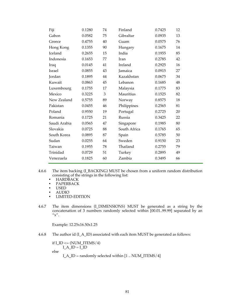
81
Fiji 0.1280 74 Finland 0.7425 12 Gabon 0.0582 75 Gibraltar 0.0935 13 Greece 0.4755 40 Guam 0.0575 76 Hong Kong 0.1355 90 Hungary 0.1675 14 Iceland 0.2655 15 India 0.1955 85 Indonesia 0.1653 77 Iran 0.2785 42 Iraq 0.0145 41 Ireland 0.2925 16 Israel 0.0855 43 Jamaica 0.0915 27 Jordan 0.1895 44 Kazakhstan 0.0675 34 Kuwait 0.0863 45 Lebanon 0.1685 48 Luxembourg 0.1755 17 Malaysia 0.1775 83 Mexico 0.3225 3 Mauritius 0.1525 82 New Zealand 0.5755 89 Norway 0.8575 18 Pakistan 0.0455 46 Philippines 0.2565 81 Poland 0.9550 19 Portugal 0.2725 20 Romania 0.1725 21 Russia 0.3425 22 Saudi Arabia 0.0565 47 Singapore 0.1985 80 Slovakia 0.0725 88 South Africa 0.1765 65 South Korea 0.0895 87 Spain 0.5785 50 Sudan 0.0255 64 Sweden 0.9150 23 Taiwan 0.1955 78 Thailand 0.2755 79 Trinidad 0.0729 51 Turkey 0.2895 49 Venezuela 0.1825 60 Zambia 0.3495 66
4.6.6 The item backing (I_BACKING) MUST be chosen from a uniform random distribution consisting of the strings in the following list:
• HARDBACK • PAPERBACK • USED • AUDIO • LIMITED-EDITION
4.6.7 The item dimensions (I_DIMENSIONS) MUST be generated as a string by the concatenation of 3 numbers randomly selected within [00.01..99.99] separated by an “x”.
Example: 12.25x16.50x1.25
4.6.8 The author id (I_A_ID) associated with each item MUST be generated as follows:
if I_ID <= (NUM_ITEMS/4) I_A_ID = I_ID else I_A_ID = randomly selected within [1 .. NUM_ITEMS/4]
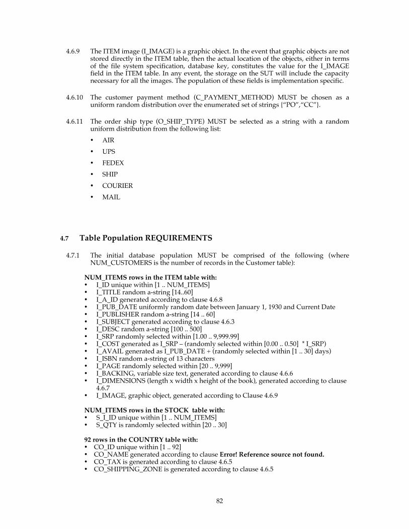
82
4.6.9 The ITEM image (I_IMAGE) is a graphic object. In the event that graphic objects are not stored directly in the ITEM table, then the actual location of the objects, either in terms of the file system specification, database key, constitutes the value for the I_IMAGE field in the ITEM table. In any event, the storage on the SUT will include the capacity necessary for all the images. The population of these fields is implementation specific.
4.6.10 The customer payment method (C_PAYMENT_METHOD) MUST be chosen as a uniform random distribution over the enumerated set of strings {“PO”,“CC”}.
4.6.11 The order ship type (O_SHIP_TYPE) MUST be selected as a string with a random uniform distribution from the following list:
• AIR
• UPS
• FEDEX
• SHIP
• COURIER
4.7 Table Population REQUIREMENTS
4.7.1 The initial database population MUST be comprised of the following (where NUM_CUSTOMERS is the number of records in the Customer table):
NUM_ITEMS rows in the ITEM table with: • I_ID unique within [1 .. NUM_ITEMS] • I_TITLE random a-string [14..60] • I_A_ID generated according to clause 4.6.8 • I_PUB_DATE uniformly random date between January 1, 1930 and Current Date • I_PUBLISHER random a-string [14 .. 60] • I_SUBJECT generated according to clause 4.6.3 • I_DESC random a-string [100 .. 500] • I_SRP randomly selected within [1.00 .. 9,999.99] • I_COST generated as I_SRP – (randomly selected within [0.00 .. 0.50] * I_SRP) • I_AVAIL generated as I_PUB_DATE + (randomly selected within [1 .. 30] days) • I_ISBN random a-string of 13 characters • I_PAGE randomly selected within [20 .. 9,999] • I_BACKING, variable size text, generated according to clause 4.6.6 • I_DIMENSIONS (length x width x height of the book), generated according to clause
4.6.7 • I_IMAGE, graphic object, generated according to Clause 4.6.9 NUM_ITEMS rows in the STOCK table with: • S_I_ID unique within [1 .. NUM_ITEMS] • S_QTY is randomly selected within [20 .. 30]
92 rows in the COUNTRY table with: • CO_ID unique within [1 .. 92] • CO_NAME generated according to clause Error! Reference source not found. • CO_TAX is generated according to clause 4.6.5 • CO_SHIPPING_ZONE is generated according to clause 4.6.5

83
(NUM_ITEMS / 4) rows in the AUTHOR table with: • A_ID unique within [1 .. (NUM_ITEMS / 4)] • A_FNAME random a-string [3 .. 20] • A_LNAME random a-string [3 .. 20] NUM_CUSTOMERS = (192 * Configured EBs) rows in the CUSTOMER table with: • C_ID unique within [1 .. 192 * Configured EBs] • C_BUSINESS_NAME generated according to clause 4.6.1 • C_BUSINESS_INFO random a-string [40..100] • C_PASSWD generated according to clause 4.6.2 • C_CONTACT_FNAME random a-string [8 .. 15] • C_CONTACT_LNAME random a-string [8 .. 15] • C_ADDR_ID = C_ID • C_CONTACT_PHONE random n-string [9 .. 16] • C_CONTACT_EMAIL generated according to clause 4.6.4 • C_PAYMENT_METHOD generated according to clause 4.6.9 • C_CREDIT_INFO random a-string [40..300] • C_PO randomly selected within [1..1000000] • C_DISCOUNT randomly selected within [0.00 .. 50.00] (10 * NUM_CUSTOMERS) rows in the ORDERS table with: • O_ID unique within [1 .. (10 * NUM_CUSTOMERS)] • O_C_ID selected so each C_ID is used exactly 10 times • O_DATE generated as current Date and Time – random within [1 .. 60] days • O_SUB_TOTAL generated as sum of (OL_I_COST * OL_QTY) for this ORDER • O_TAX generated as O_SUB_TOTAL * 0.0825 • O_SHIP_TYPE selected at random from the list in clause 4.6.11 • O_PROCESS_DATE generated as O_DATE + random within [0 .. 7] days • O_SHIP_COST = 3.00 + (1.00 * count_of_items_in_order) • O_TOTAL generated as O_SUB_TOTAL + O_TAX + O_SHIP_COST • O_SHIP_ADDR_ID = randomly selected within [1 ..cardinality of ADDRESS table] • O_STATUS set to SHIPPED • O_DISCOUNT set to zero • O_AUTH_ID set to ’INITIALPOP’ For each row in the ORDERS table, a number of rows in the ORDER_LINE table, where the number is randomly selected within [1..10] with: • OL_ID unique within [1 .. number of ORDER_LINEs for this ORDER] • OL_O_ID = O_ID • OL_I_ID randomly selected within [1 .. NUM_ITEMS] and unique within each
ORDER • OL_QTY randomly selected within [1 .. 10] • OL_STATUS set to SHIPPED • OL_I_COST randomly selected within [1.00 .. 9,999.99]
(1.4 * NUM_CUSTOMERS, rounded up to the nearest integer) rows in the ADDRESS table with: • ADDR_ID unique within the cardinality of the ADDRESS table. • ADDR_STREET1 random a-string [15 .. 40] • ADDR_STREET2 random a-string [15 .. 40] • ADDR_CITY random a-string [4 .. 30] • ADDR_STATE random a-string [2 .. 20] • ADDR_ZIP random a-string [5 .. 10] • ADDR_CO_ID random within [1 .. 92]
84
4.7.2 The implementation MUST NOT take advantage of the fact that some fields are initially populated with a fixed value. For example, storage space cannot be saved by defining a default value for any particular field and storing this value only once in the database.
4.8 Customized Load Utilities
The load program MUST use the random number generator as defined in clause 6.4 for all random data generation REQUIREMENTS.

85
Clause 5 - PERFORMANCE METRICS AND RESPONSE TIME
The four primary metrics of the TPC-App benchmark are the SIPS per Application Server SYSTEM, the Total SIPS, Price / Performance defined as total price of the Priced Configuration / Total SIPS (e.g., $(USD)/SIPS), and the Availability Date.
5.1 Web Service Interaction Mix REQUIREMENTS
The TPC-App workload comprises a set of Web Service Interactions specified in detail in Clause 2. Over the Measurement Interval, each Active EB MUST target the mix of Web Service Interactions specified in the table below. The aggregate mix across all Active EBs MAY deviate from the specified percentages as a natural result of the finite random selection process. The maximum overall deviation allowed for all EBs as a group is (0.01 x P) where P is any of the REQUIRED mix percentages. Example: If the Create Order Web Service Interaction is 50.00%, it is REQUIRED that the average mix percentage of Create Order occuring during the Measurement Interval is within [49.5% .. 50.5%].
Comment 1: For the purpose of computing the mix, one MUST count only the successful Web Service Interactions.
Comment 2: All successful Web Service Interactions occurring within the Measurement Interval must be counted for the mix computation.
Mix of Web Service Interactions
Web Service Interaction Type Required Mix
New Customer 1.00%
Change Payment Method 5.00 %
Create Order 50.00 %
Order Status 5.00 %
New Products 7.00 %
Product Detail 30.00 %
Change Item 2.00 %
5.1.1 Regulation of Transaction Mix

86
Web Service Interaction Types MUST be selected randomly while maintaining the REQUIRED percentage of mix for each Web Service Interaction Type over the Measurement Interval. This MUST be done using the following technique: A weight between 0.00 and 1.00 is associated to each Web Service Interaction Type specified in the above table. The sum of all the weights MUST be 1.00. The REQUIRED mix is achieved by selecting each new Web Service Interaction Type randomly from this weighted distribution. For the purpose of achieving the REQUIRED Transaction mix, the Active EB MUST NOT dynamically adjust the weight associated with each Web Service Interaction Type during the Measurement Interval.
Each Active EB can have at most one outstanding Web Service Interaction at any point in time. This means that the Active EB MUST wait for the preceding Web Service Interaction to complete successfully before submitting a request for the next Web Service Interaction.
A RETRY is defined to be a resubmission of a Web Service Request by an EB, or by the RBE on behalf of the EB. Some examples of conditions that would require a RETRY are:
• a networking error (e.g., a connection reset) • receipt of an HTTP status in the range 4xx-5xx (e.g, a status of 400 Bad
Request due to malformed HTTP request, or not well-formed XML) • receipt of a Web Service Response that contains a SOAP fault (see clause 2.1.22).
Comment 1: A resubmission due to receipt of an HTTP status of 307 is not considered to be a RETRY. Note: As prescribed by the WS-I BP1.0 specification, HTTP status 307 MUST only be used for redirection to a different endpoint.
During each Web Service Interaction the EB maintains a count of RETRYs (initialized to be zero), called the RETRY_COUNT. After each RETRY the EB increments the RETRY_COUNT by one.
If the first Web Service Response does not meet the Web Service Interaction Output Requirements, or the SUT has not performed all the business logic specified in the Processing Definition for the Web Service Interaction type, the EB MUST perform RETRYs until either a successful Web Service Interaction has occurred, or until the RETRY_COUNT has reached 20. If the 20th RETRY does not result in a successful Web Service Interaction the Test Run is invalid.
Comment 2: In general, one cannot assume that Web services are repeatable operations upon receipt of a failure. For the purposes of this benchmark however, all Web Service Interactions are considered repeatable. Resubmissions MUST NOT introduce errors due to the Application Program's inability to handle a repeat Web Service Request (e.g., duplicate key violation).
Comment 3: If the environment used to implement the EB provides a facility to implicitly resubmit Web Service Interactions under certain failure scenarios, that facility may only be used if it provides some means to record the resubmission and increment the RETRY_COUNT.
Comment 4: It not permissible to prematurely close the Business Session as an error recovery mechanism.
Comment 5: An active EB MAY insert an artificial delay as part of the retry process. This delay MUST NOT exceed 30 seconds per retry attempt. Note that this delay MUST be included in the SIRT.

87
5.1.2 Shipping and Stock Management REQUIREMENTS
Shipping and Stock Management are background processes that are not driven by the RBE directly. They are not counted as part of the mix.
For every Create order Web Service Interaction, a corresponding Durable Message is queued to the Shipping process (see clause 2.5). Additionally the stock management process places BACK_ORDERED items on the shipping queue once stock has been ordered. During the Measurement Interval, the Shipping Process MUST successfully ship (meaning O_STATUS = SHIPPED) at least 99.8% of the orders created during the Measurement Interval. Any rollback in the Shipping Process MUST NOT be counted as successfully processed.
For every Shipping queue entry with a status of BACK_ORDERED, a corresponding Durable Message is queued to the Stock Management Process (see clause 2.6). Any rollback in the Shipping Process MUST NOT be counted as successfully processed. See clause 8.7 for reporting REQUIREMENTS.
5.2 Web Service Interaction Response Time 5.2.1 Web Service Interaction Response Time (SIRT)
The Web Service Interaction Response Time (SIRT) is the time taken to perform a successful Web Service Interaction by an Active EB. It is defined as:
SIRT = T2 - T1
Where:
T1 and T2 are measured at the RBE machine;
T1 = a time measured before the first byte of the Web Service Interaction’s first SOAP message is sent by the RBE to the SUT; and
T2 = a time measured after the last byte of the Web Service Interaction’s last SOAP message is received by the RBE from the SUT;
and where T1 and T2 are subject to the following additional REQUIREMENTS:
5.2.1.1 SIRTs are defined only for successful Web Service Interactions.
5.2.1.2 The resolution of the time stamps MUST be at least 0.2 seconds.
Comment: This resolution value is chosen to accommodate platforms that limit time stamp resolution to a 60 Hz-based clock.
5.2.1.3 T1 for the next Web Service Interaction performed by the EB is defined to be T2 of the current Web Service Interaction. That is, Next T1 = T2. ( See Appendix H for rationale.) For an Active EB, for its first Web Service Interaction in the Test Run T1, MUST be set to a time no later than TFB for the first Web Service Interaction of the first Business Session and no earlier than the beginning of the Test Run.
5.2.1.4 Define TFB as the time just prior to the RBE’s sending, to the SUT, the first byte REQUIRED for making the Web Service Request. TFB is always prior to the sending of the HTTP headers bytes of the Web Service Request. If TCP/IP protocol bytes or SSL/TLS protocol bytes MUST be sent prior to sending the Web Service Request, then TFB occurs prior to these bytes. For example, TFB MUST precede any TCP/IP connection open, or any SSL/TLS handshaking that is necessary prior to the Web Service Request.
5.2.1.5 Define TLB as the time just after the RBE’s receipt of the last byte of the last Web Service Response for the Web Service Interaction.
88
5.2.1.6 Define TCK as the time just after the EB has verified that Web Service Interaction was a successful Web Service Interaction.
5.2.1.7 These temporal relations MUST hold: T1 TFB, TLB T2, T2 = Next T1, TCK < Next TFB, Next T1 Next TFB.
Comment 1: TCK < Next TFB is REQUIRED because the EB MUST NOT start its next Web Service Interaction until it has confirmed whether its current Web Service Interaction is successful or unsuccessful (see clause 5.1.1).
Comment 2: Note that there is no fixed ordering between T2 and TCK. That is, T2 could be earlier than, the same as, or later than TCK.
5.2.1.8 The following diagram illustrates where T1 and T2 MAY be measured, and the other temporal relations.
• The shaded boxes are computations performed by the RBE.
• The unshaded boxes are messages that are sent between the RBE and the SUT, with the direction of communication indicated by arrows. A double-headed arrow means that messages could flow in both directions.
• Each SOAP-related box depicts one and only one SOAP message, whereas each of the non-SOAP boxes can depict one or more messages. For example, a TCP/IP Connection Open comprises several packets sent back and forth between the RBE and the SUT.
• The faint, unshaded boxes depict a set of message types that MAY or MAY NOT be sent, depending on the occurrence of errors or other protocol REQUIREMENTS. Each box depicts a type of message, and various sequences of these types of message MAY be sent. In particular, the section of faint boxes following the initial Web Service Request and before the Web Service Response is where an EB’s retrying of a Web Service Request would occur, and this could include several iterations through this section.
o For example, the box “SSL/TLS session protocol msgs” includes such message sequences as 1) a full handshake to establish an SSL session, 2) a simple session resumption handshake.
o For example, the box “HTTP Header / Status” depicts an HTTP message containing a status of 4xx or 5xx that MAY be sent to the RBE. The RBE MAY then retry the request by resending the Web Service Request SOAP message.
o For example, a SOAP Fault message MAY be sent to the RBE, with the RBE subsequently resending the Web Service Request SOAP message.
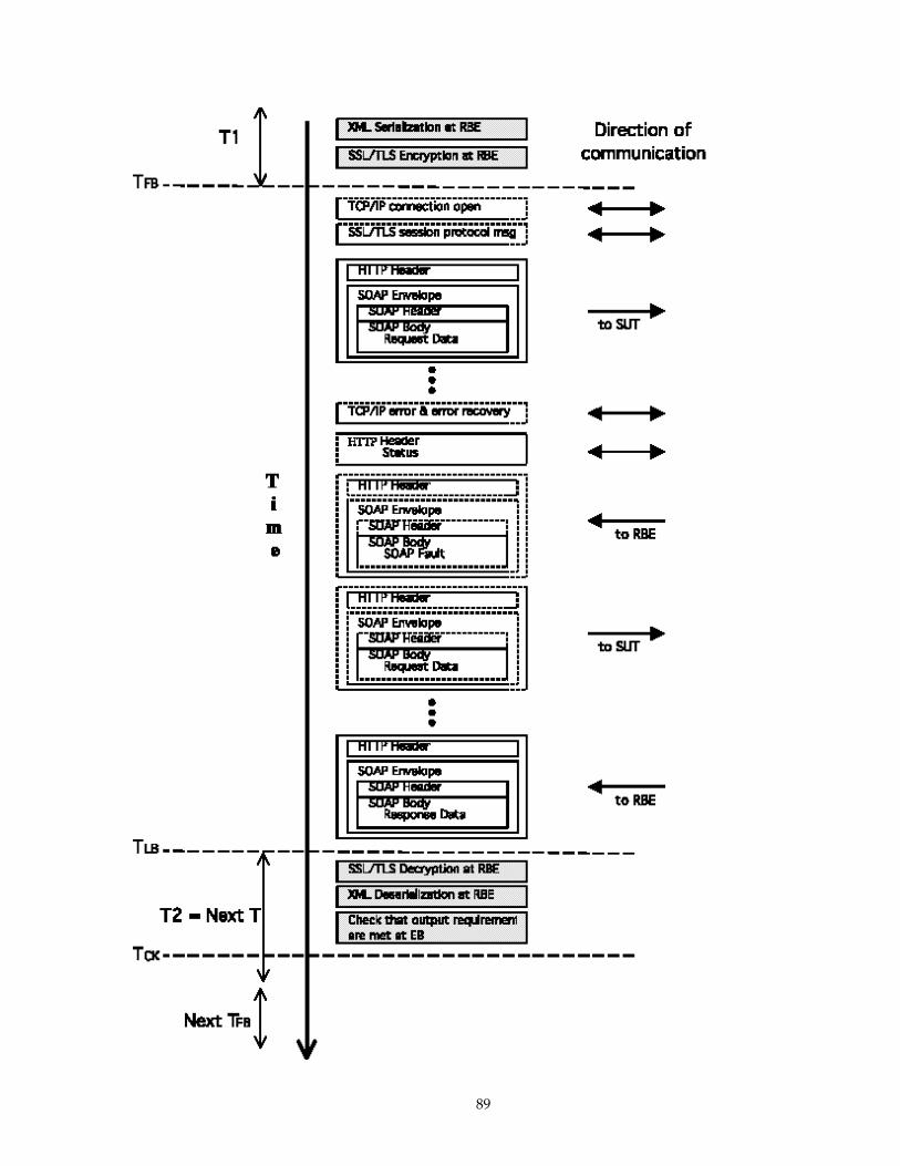
89

90
5.2.2 During the Measurement Interval, at least 90% of the successful Web Service Interactions for each Web Service Interaction Type MUST have a SIRT of less than the constraint specified (in seconds) for that Web Service Interaction Type in the table below. For example, at least 90% of all successful Create Order Web Service Interaction MUST have a SIRT of less than 4 seconds.
New
Cu
stom
er
Ch
ange
Pay
men
t M
eth
od
Cre
ate
Ord
er
Ord
er S
tatu
s
New
Pro
du
cts
Pro
du
ct D
etai
l
Ch
ange
Ite
m
90% SIRT Constraint (in Seconds)
3.0 3.0 4.0 4.0 1.0 1.0 1.0
5.2.3 Over the Measurement Interval, for each Web Service Interaction Type, the average SIRT of the successful Web Service Interactions MUST be no more than 0.1 second longer than the 90th percentile SIRT.
5.3 Computation of Throughput Rating
5.3.1 The throughput for the Measurement Interval is computed as the total number of successful Web Service Interactions within the Measurement Interval divided by the length of the Measurement Interval in seconds.
All successful Web Service Interactions whose SIRT is fully within the bounds of the Measurement Interval MUST be included in the computation of the reported throughput.
Web Service Interactions MUST NOT be included in the computation of the reported throughput if their SIRT is not fully within the bounds of the Measurement Interval.
5.3.2 The reported Total SIPS throughput is REQUIRED to satisfy the following inequalities: .089 * Active EBs Total SIPS 1.78 * Active Ebs See Appendix G - for the derivation of the formula.
5.3.3 The reported throughput MUST be measured, rather than interpolated or extrapolated, and expressed to exactly one decimal place, truncated to the tenths place. For example, suppose 105.578 SIPS is measured on a test for which all 90% SIRT constraints are met and 117.572 SIPS is measured on a test for which some 90% SIRT constraints are exceeded. Then the reported SIPS is 105.5 rather than some interpolated value between 105.578 and 117.572. This means any Measurement Interval that does not meet the 90% REQUIREMENTS is not valid.
5.4 Test Run REQUIREMENTS
The Test Run consists of a Ramp-Up Period followed by Stabilization Period followed by Steady State Period; the latter contains the reported Measurement Interval.
5.4.1 At least one checkpoint MUST be started and completed after Ramp-Up Period and before the start of the Measurement Interval.
91
5.4.2 Consistency conditions 3,4,6, and 9 MUST be met immediately after the end of the Test Run to be considered a valid Test Run. The end of the Test Run is the time when all Active EBs have stopped submitting Web Service Requests, and all Shipping and Stock Management Queues have been completely processed.
5.4.3 Steady State
5.4.3.1 The reported throughput MUST be computed over a Measurement Interval during which the throughput level is in a Steady State condition that represents the true sustainable and repeatable performance of the SUT. Steady State is easy to define (e.g., sustainable throughput) but difficult to prove. The auditor is REQUIRED to report the method used to verify the Steady State sustainable throughput of measured results. The auditor is encouraged to use available monitoring tools to help determine the Steady State. The Steady State Period MUST be at least 3 hours.
5.4.3.2 The number of Active EBs during the Test Run MUST be at least 90% and not more than
100% of the Configured EBs. 5.4.3.3 Some aspects of the benchmark implementation can result in systematic but small
variations in sustained throughput. These variations MUST be limited to 2% of the reported throughput over the Steady State Period. During the Steady State Period, no interval with duration of 30 minutes (with a granularity of 30 seconds) can have a computed throughput that is lower than 98% of the reported throughput or higher than 102% of the reported throughput.
Comment: This is an attempt to detect situations that would degrade performance over a longer run (e.g., memory leaks, disk fragmentation, etc...)
5.4.3.4 To prevent significant alteration to the properly scaled database population, the mix of Web Service Interactions and the REQUIREMENTS summarized in clause 5.5 MUST be followed during the entire Test Run as well as during any other time between Test Runs. (See clause 4.6)
5.4.4 Measurement Interval
5.4.4.1 The Measurement Interval MUST extend uninterrupted for a minimum of 2 hours within the Steady State Period.
5.4.4.2 Although the Measurement Interval MAY be as short as 120 minutes, the SUT MUST be configured so that it is possible to run the mix of Web Service Interactions at the reported throughput rate for 8 hours of uninterrupted execution (as defined in clause 6.12.1) while maintaining full ACID properties.
Comment 1: For example, the media used to store the database log data until it can be archived without interruption of processing, if necessary to recover from any single point of failure, MUST be configured for 8 hours of operation.
Comment 2: An example of a configuration that would not comply is one where a log file is allocated such that better performance is achieved during the measured portion of the run than during the remaining portion of any full throughput period (perhaps because a dedicated device was used initially but space on a shared device is used later in the full throughput period).
92
Comment 3: An example of a compliant implementation would be one where the entire database is placed on redundant storage and the database log data is stored on circular files large enough to span a complete checkpoint cycle.
5.4.5 Checkpoints
5.4.5.1 Some systems do not write modified database records/pages to durable media at the time of modification, but instead defer these writes. At some subsequent time, the modified records/pages are written to make the durable copy current. This process is defined as a checkpoint in this document.
5.4.5.2 It is a requirement that no recovery data older than 30 minutes prior to an instantaneous interruption be used for recovery. The consequence of this requirement is that the database contents stored on durable media MUST NOT at any time during the Test Run be more than 30 minutes older than the most current state of the database (±5%).
Comment: Within the Measurement Interval the start of any checkpoint and the end of the next checkpoint cannot exceed 30 minutes.
5.4.5.3 All work necessary to perform a checkpoint MUST occur in full at least once before the Measurement Interval begins but after the Ramp-Up Period.
5.5 Measurement Interval REQUIREMENTS
The following REQUIREMENTS MUST all be met for a Measurement Interval to be valid. A measurement interval that is not valid MUST be considered to be non-compliant. All of these REQUIREMENTS refer to metrics that were taken throughout the entire Measurement Interval.
1. At least 99.8% of the orders created during the Measurment Interval must be SHIPPED
within the Measurement Interval. The test for this can be achieved by comparing the count of the number of orders where O_DATE and O_PROCESS_DATE are within the Measurement Interval to the number of orders where O_DATE is within the Measurement Interval.
2. The percentage of New Customer requests that chose “PO” as the payment method
MUST be within [49.5% .. 50.5%]. 3. The percentage of Change Payment Method requests that chose “PO” as the payment
method MUST be within [49.5% .. 50.5%]. 4. The percentage of Create Order requests that include a shipping address change MUST
be within [4.95% .. 5.05%]. 5. The number of Create Order requests that had one item BACK_ORDERED MUST be
within [9.95% .. 10.05%]. 6. The mix of Web Service Interactions MUST meet the REQUIREMENTS as specified in
clause 5.1. 7. The mix of Web Service Interaction on each Application Server SYSTEM must meet the
requirements of clause 2.1.11. 8. The message queue processing requirements in clause 2.1.12 MUST be met. 9. The Measurement Interval MUST be selected from a valid Test Run (see clause 5.4). 10. The response time constraints MUST be met as per clause 5.2.1.

93
Clause 6 - SUT, RBE AND NETWORK DEFINITIONS
6.1 Remote Business Emulator (RBE)
6.1.1 The Remote Business Emulator (RBE) is the software component that drives the TPC-App workload. It emulates businesses that issue Web Service Requests to the System Under Test (SUT).
6.1.2 The RBE creates and manages an Emulated Business client (EB) for each emulated Business. The term RBE, when used in this specification, includes the entire population of Active EBs.
6.1.3 The RBE MUST use secure communication for all SUT Web Service Interactions (see clause 2.1.1).
6.1.4 The RBE is responsible for the following:
• Conforming to all execution rules specified in this document
• Conforming to all industry standards specified in this document, e.g., SSL/TLS
• Generating random numbers, timestamps, strings as REQUIRED to implement the benchmark
• Selection of the Web Service Interaction Types for the Active EBs.
• Recording the counts and percentages of the mix of Web Service Interactions requested and successfully completed.
• Recording SIRT and throughput in accordance with the REQUIREMENTS of Clause 5
6.1.5 The RBE MUST not perform any processing ordinarily performed by the SUT. This includes, but is not limited to:
• Caching of any data returned by the Application Program, files or database tables, except as specifically noted in clause 2 and in clause 6.3.1, as REQUIRED to execute the RBE functions.
• Searching files or databases except as REQUIRED to execute RBE functions
• Caching disk addresses or pointers to database records on the SUT
• Performing computations such as shipping cost, tax, etc. that belong to the SUT
• Communicating information to the SUT regarding future Web Service Requests
• Executing active elements (e.g., Java scripts or applets) communicated by the SUT
• Load balancing or routing across multiple components of the SUT.
6.1.6 The SUT and RBE MUST open a new socket connection for each Business Session. A socket connection MUST NOT be used by more than one Active EB. Furthermore, if the SUT allows persistent sessions, also known as keep-alive (as specified in HTTP 1.1), the duration parameters for persistent sessions (i.e. time limit and request limit) MUST be disclosed. The RBE MAY open multiple socket connections per Business Session.
94
6.1.7 The communication between the Active EBs and the SUT MUST NOT use a TCP Maximum Segment Size (MSS) greater than 1,460 bytes.
6.1.8 The Web Service Interaction response timeout value MUST be configured to be no more than 90 seconds. If a Web Service Response takes longer than this, it MUST be treated as a SOAP Fault and the retry logic in clause 0 MUST be applied.
6.1.9 Active EBs must use the same URL for any given Web Service Interaction.
6.1.10 During the Test Run an Active EB MUST NOT introduce any artificial delay. Examples of artificial delay include sleeps or spin constructs that are unnecessary for the implementation of the Transaction mix. The exception to this rule is during the error retry process (see clause 0).
6.2 Business Session Length 6.2.1 The Business Session Length (BSL) is the number of Web Service Interactions that are
targeted to be performed by the Active EB during a Business Session. The Active EB generates random BSLs in accordance with the discrete distribution defined by the BSL Cumulative Distribution Function (CDF) in Appendix C - .
Comment: Appendix D - describes how to obtain source for code that SHOULD be used to generate the BSLs. It is recommended, but not REQUIRED, that this code be used. However, if this code is not used, or if a modification or augmentation of this code is used, then the code used to generate BSLs MUST disclosed in the FDR.
6.2.2 For a given Measurement Interval, the average BSL is computed as the average of the BSL for all sessions beginning during that Measurement Interval. If the session does not end before the close of the Measurement Interval, the BSL calculated for that session MUST still be included in the average BSL.
6.2.3 Business Session Termination
6.2.3.1 A Business Session ends when the Active EB has completed the BSL number of Web Service Interactions.
6.2.3.2 When the Business Session ends, the Active EB takes the following actions: • The Active EB MAY close any SSL/TLS session that is currently established for the
Business Session. • The Active EB MAY close all network connections that are currently established for
the Business Session. • The Active EB is REQUIRED to immediately start a new Business Session.
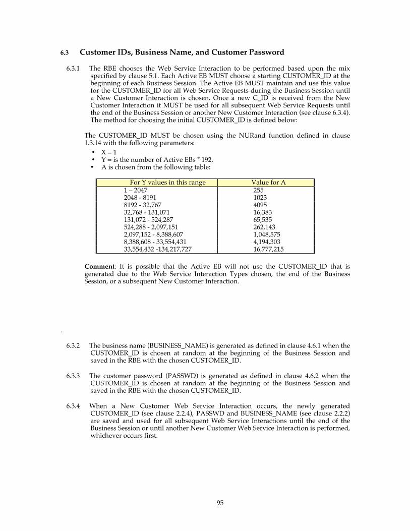
95
6.3 Customer IDs, Business Name, and Customer Password
6.3.1 The RBE chooses the Web Service Interaction to be performed based upon the mix specified by clause 5.1. Each Active EB MUST choose a starting CUSTOMER_ID at the beginning of each Business Session. The Active EB MUST maintain and use this value for the CUSTOMER_ID for all Web Service Requests during the Business Session until a New Customer Interaction is chosen. Once a new C_ID is received from the New Customer Interaction it MUST be used for all subsequent Web Service Requests until the end of the Business Session or another New Customer Interaction (see clause 6.3.4). The method for choosing the initial CUSTOMER_ID is defined below:
The CUSTOMER_ID MUST be chosen using the NURand function defined in clause 1.3.14 with the following parameters: • X = 1 • Y = is the number of Active EBs * 192. • A is chosen from the following table:
For Y values in this range Value for A 1 – 2047 255 2048 - 8191 1023 8192 - 32,767 4095 32,768 - 131,071 16,383 131,072 - 524,287 65,535 524,288 - 2,097,151 262,143 2,097,152 - 8,388,607 1,048,575 8,388,608 - 33,554,431 4,194,303 33,554,432 -134,217,727 16,777,215
Comment: It is possible that the Active EB will not use the CUSTOMER_ID that is generated due to the Web Service Interaction Types chosen, the end of the Business Session, or a subsequent New Customer Interaction.
.
6.3.2 The business name (BUSINESS_NAME) is generated as defined in clause 4.6.1 when the CUSTOMER_ID is chosen at random at the beginning of the Business Session and saved in the RBE with the chosen CUSTOMER_ID.
6.3.3 The customer password (PASSWD) is generated as defined in clause 4.6.2 when the CUSTOMER_ID is chosen at random at the beginning of the Business Session and saved in the RBE with the chosen CUSTOMER_ID.
6.3.4 When a New Customer Web Service Interaction occurs, the newly generated CUSTOMER_ID (see clause 2.2.4), PASSWD and BUSINESS_NAME (see clause 2.2.2) are saved and used for all subsequent Web Service Interactions until the end of the Business Session or until another New Customer Web Service Interaction is performed, whichever occurs first.
96
6.4 Random Number Generation
The RBE, the SUT, and the program used to generate the initial database population MUST use the 64 bit random number generator described in Appendix A - for all random number generation.
6.5 System Under Test (SUT)
The SUT comprises all components that are part of the application being simulated. This includes network connections, the application server SYSTEM, and database server SYSTEM.
6.5.1 SUT Components
For Non-Clustered results, the SUT MUST consist of at most one Application Server SYSTEM. For Non-Clustered results utilizing exactly one Application Server SYSTEM, the other SYSTEMs MUST host only the Database Server and any components that are REQUIRED to implement the ACID properties of the database and Distributed Transactions. The Application Server SYSTEM MUST host the Application Server(s) and MUST perform all other functions of the SUT. When the SUT contains only a single SYSTEM all SUT functions MUST be performed on that SYSTEM. All storage media required for storage of database data and durable messages is considered to be part of the SUT. This does not include any of the logs that are required for the external emulators. The SYSTEMs that are not hosting the Database Server MUST host the Application Server(s) and MUST perform all other functions of the SUT. For Clustered results, there is no restriction on the number of application server SYSTEMs or database server SYSTEMs. For Clustered results, the database server SYSTEMs MUST host only the Database Server and any components that are REQUIRED to implement the ACID properties of the database and Distributed Transactions. The other SYSTEMs MUST host the Application Server(s) and MUST perform all other functions of the SUT. For Clustered results, the application server SYSTEMs MUST be configured identically (see clause 0). The application server SYSTEMs MUST be configured such that they each provide all of the Application Server functionality REQUIREMENTS. For a SUT that contains more than 1 SYSTEM, the SYSTEM(s) which hosts the Database Server MUST not perform the XML serialization of the output response that is ultimately returned to the EB. However, it MAY use XML to communicate with the Application Server. If XML is used in communications between the Application Server and the Database Server, the XML data from the Database Server response MUST be deserialized to form the Web Service Response to the Active EB. For Non-Clustered and Clustered results, it is permissible to have the Distributed Transaction Manager and/or its components on either the Application Server SYSTEMs, the Database Server SYSTEMs, or both, provided that the requirements of clause 1.2.57 and clause 0 are met.

97
For Non-Clustered and Clustered results, all SSL/TLS processing, MUST take place inside the SYSTEM(s) that make up the SUT. There is no limitation on the type or number of cards that MAY be connected to the internal bus of a SYSTEM (e.g. PCI bus). For Non-Clustered and Clustered results, external appliance(s) and devices are permitted to provide only load balancing and/or system initialization functionality. Comment 1: This clause does not preclude the use of external disk storage devices; however those devices MUST only be used for persistent data storage and durability. The intent is to prohibit the use of SAN technologies from offloading TPC-App workload REQUIREMENTS. Network equipment that performs only connectivity between the SUT and the active Ebs is considered to be outside of the SUT. The functions that MUST NOT be performed by this network equipment include but are not limited to the following:
• SSL/TLS processing • Connection management above the network layer (see B.12[OSI reference
model]) • XML serialization or de-serialization • Communication between SUT components
Comment 2: If a network component is used to perform both connectivity and load balancing (with the exception of clause 2.1.5) then it MUST be considered as part of the SUT and the Priced Configuration. A load balancer is permitted in the SUT subject to the restrictions of 6.5.3. Comment 3: External appliance(s) are permitted only to provide load balancing and/or system initialization functionality.
6.5.2 Functions of the SUT
6.5.2.1 The SUT services the following:
• SOAP requests via the HTTP protocol (conforming to the WS-I Basic Profile 1.0 Specification), by returning the output REQUIREMENTS in a Web Service Response (see clause 1.2.47).
6.5.2.2 The SUT performs the following operations:
• All database accesses. The database MUST be accessed using a Commercially Available interface.
• All communication functions to and from the RBE, POV, PGE, SNE and ICE. These communications MUST conform to the WS-I Basic Profile 1.0 Specification and are REQUIRED to use TCP/IP sockets (i.e. RFC 1122, etc.)
• All application functionality REQUIRED to implement the Web Service Interactions.
Comment: If a load balancing product is used on the SUT to direct requests between the RBE and a group of application servers it is subject to the following restrictions:
• It MUST NOT perform any connection management (e.g., multiplexing,
connection pooling, etc) • It MUST NOT perform any XML serialization or de-serialization. • It MUST NOT perform any SSL or TLS functions
98
6.5.3 SUT Restrictions
Within this sub-clause the following terms have these specific meanings : • The term caching is as defined in clause 1.2.25. • The term cache means a data store that holds the data being retrieved via caching. • The term cached refers to data stored in a cache as defined in this clause.
6.5.3.1.1 The tables where caching MAY be used, subject to the restrictions in clause 6.5.3 are listed below. Caching MUST NOT be used on any of the other tables defined in Clause 1.5.
• COUNTRY • AUTHOR • ITEM
6.5.3.1.2 If used, caching MUST only be performed on the Application Server SYSTEM(s). Additionally, caches must be contained in, and managed by, Commercially Available components of the Application Server SYSTEM(s).
99
6.5.3.1.3 If caching is used, all cached copies MUST maintain full atomicity, isolation, and consistency (ACI) with the copy stored in the Database Server. The test sponsor MUST NOT maintain these ACI properties via the Application Program.
6.5.3.1.4 Operations to manage the state of and ensure the consistency of the cached copies MUST NOT be performed or initiated by the Application Program. For example, the Application Program MUST NOT disable, insert, update, or remove items/data from a cache. The only exception to this is that the Application Program MAY enable a cache to store selected items/data.
6.5.3.1.5 Caching MUST be performed in a manner such that updates to a cached copy is reflected in that cache for any arbitrary (not TPC-App) interaction or update.
6.5.3.1.6 If a programmatic interface (API) is necessary for the caching software, this MUST be part of a commercial product.
6.5.3.1.7 All data requests that result in the retrieval of cached data MUST be made directly to Commercially Available components of the Application Server SYSTEM(s), or must be transparently intercepted by components of the Application Server(s).
6.5.3.2 The Application Program MUST NOT take advantage of the knowledge of the effects one Web Service Interaction MAY have on another Web Service Interaction to increase the efficiency of caching.
6.5.3.3 The operations performed by the Application Program during a given Web Service Request MUST NOT perform any step of the Processing Definition on behalf of any other Web Service Request.
Comment: This is to prevent the Application Program from forwarding data from one request to another.
6.6 Purchase Order Validation (POV)
6.6.1 The Purchase Order Validation (POV) represents a Web service (external to the SUT) that authorizes credit for either a new customer or an existing customer that is changing to a purchase order method for payments. Inputs to the POV are the BUSINESS_NAME and CREDIT_INFO.
6.6.2 The POV is not included in the SUT.
6.6.3 The POV MUST perform the following functions: • Establish an SSL/TLS session at the SUT’s request • Receive properly formed SOAP messages from the SUT • For each encrypted SOAP message received from the SUT:
1. Decrypt the message. The message MUST contain the following fields: • BUSINESS_NAME • PO_ID
2. Generate an authorization code, AUTH_ID, as a unique dec(16) (unique within this Test Run)
3. Record the BUSINESS_NAME and PO_ID in a POV log. 4. Generate the SOAP response message containing the AUTH_ID. 5. Encrypt and send the SOAP response message back to the SUT.
Each POV response MUST be sent in a separate SOAP message.
100
Comment: The exact format of the POV log is not defined and is left up to the implementor
6.6.4 The response time between the reception of a given SOAP message from the SUT and the communication of the POV’s response SOAP message to the SUT MUST be no less than 2 seconds.
6.7 Payment Gateway Emulator (PGE)
6.7.1 The Payment Gateway Emulator (PGE) represents a Web service (external to the SUT) that authorizes credit card payment of funds as part of the Create Order Web Service Interaction. Inputs include the credit card holder’s name (CC_NAME) and the credit card number (CC_NUMBER) and expiration date (CC_EXPIRY).
6.7.2 The PGE is not included in the SUT.
6.7.3 The PGE MUST perform the following functions:
• Establish an SSL/TLS session at the SUT’s request • Receive properly formed SOAP messages from the SUT • For each encrypted SOAP message received from the SUT:
1. Decrypt the message 2. Extract the CC_NAME, CC_NUMBER, and CC_EXPIRY from the PGE request
message 3. Generate an authorization code, AUTH_ID, as a unique dec(16) (unique within
this Test Run) 4. Record the AUTH_ID and the current date and time of the PGE SYSTEM in a
PGE log. The clocks on the SYSTEM(s) that handle the PGE requests MUST be synchronized to be within 1 second of the SUT.
5. Generate the SOAP response message containing the AUTH_ID. 6. Encrypt and send the SOAP response message back to the SUT.
Each PGE response MUST be sent in a separate SOAP message.
Comment: The exact format of the PGE log is not defined and is left up to the implementor
6.7.4 The response time between the reception of a given SOAP message from the SUT and
the communication of the PGE’s response SOAP message to the SUT MUST be no less than 2 seconds.
6.8 Inventory Control Emulator (ICE)
6.8.1 The Inventory Control Emulator (ICE) represents a Web service (external to the SUT) that receives requests for additional item stock. It also simulates receipt of those items from external suppliers.
6.8.2 The ICE is not included in the SUT.
6.8.3 The ICE MUST perform the following functions:
101
• Establish an SSL/TLS session at the SUT’s request • Receive properly formed SOAP messages from the SUT • For each SOAP message received from the SUT:
1. Decrypt the message 2. Extract the REORDER_I_ID, REORDER_QTY quantity and the SHIPPING_O_ID
from the ICE request message. 3. Generate a response indicating successful receipt of request. 4. Record the SHIPPING_O_ID, and current Date and Time of the ICE SYSTEM in
an ICE log. The clocks on the SYSTEM(s) that handle the ICE requests MUST be synchronized to be within 1 second of the SUT.
5. The response message MUST be a properly formed SOAP response containing a successful receipt field.
6. Encrypt and send the SOAP success response message back to the SUT.
Each ICE response MUST be sent in a separate SOAP message .
Comment 1: The exact format of the ICE log is not defined and is left up to the implementor
Comment 2: The response time between the reception of a given message from the SUT and the communication of the ICE’s response message to the SUT is not restricted in any way.
6.9 Shipment Notification Emulator
6.9.1 The SNE is a Web service (external to the SUT) that represents a shipping vendor (FEDEX, UPS, AIR etc). This vendor will use the inputs of shipping address to return an image that represents a shipping label and tracking number for the shipment package. The SNE is not included in the SUT.
6.9.2 The SNE MUST perform the following functions:
• Establish an SSL/TLS session at the SUT’s request • Receive properly formed SOAP messages from the SUT • For each encrypted SOAP message received from the SUT:
• Decrypt the message. The message MUST contain the following fields: o Address information
SHIPPING_STREET1 SHIPPING_STREET2 SHIPPING_CITY SHIPPING_STATE SHIPPING_ZIP SHIPPING_COUNTRY
• Generate the SOAP response message containing the following fields: o TRACKING_NUMBER = “0912-7324TPC-App9234Z12” o SHIPLABEL_IMAGE is the image defined in clause 1.3.15
• Encrypt and send the SOAP response message back to the SUT.
Each SNE response MUST be sent in a separate SOAP message.
Comment: The SHIPLABEL_IMAGE may be serialized once and used throughout the Test Run.

102
6.10 Model of the Complete Tested System
The following diagram shows an example layout of RBE, POV, PGE, ICE, SNE and SUT components. All components inside the box are part of the SUT and, as such, MUST be priced (see Clause 7).
6.11 Communications Interface Definitions
6.11.1 Communication to and from the SUT
The protocols for communicating between the SUT and the RBE as well as between the SUT and the PGE, POV, SNE, and ICE MUST be SOAP over secure HTTP (see clause 0) using TCP/IP. All Web Service Interactions, including any Web service interactions with the external emulators (PGE, ICE, POV, SNE) MUST conform to the WS-I Basic Profile 1.0 Specification and MUST use secure communications (see clause 2.1.1).
Comment: Protocols used to implement RBE functions MUST either be implemented
using Commercially Available products or fully reviewed for compliance.
6.11.2 Communications within the SUT

103
The communications protocols within the SUT are not restricted. There is no requirement for SUT network hardware (e.g., network switch, hub, etc), however if such hardware is used it MUST be priced.
6.12 Operational Characteristics The objective of this benchmark is to represent a 7X24 operating environment for a
business-to-business application environment. The following are characteristics of the benchmark application that make it consistent with a 7X24 operational model. Some of these functional characteristics MAY not be actually exercised during the benchmark’s Measurement Intervals.
6.12.1 Uninterrupted Execution
The SUT MUST have the storage capacity to handle continued uninterrupted execution for 8 hours at the reported throughput.
To demonstrate continued execution capability, the following data MUST be collected for
each system that is part of the SUT at the start and end of the Test Run that contains the reported Measurement Interval (see clause 1.2.35). • Total disk space utilization in bytes • Disk space for system swapping and paging (collected prior to the shutdown of the
Application Program).
The total growth in these resources (RG) uses the following formula for each resource: RG = IR + (G / TI * Total SIPS * 3600 * 8 ) Where:
• TI is the total Web Service Interactions completed during the Test Run, • G is the growth over the Test Run, and • IR is the initial resource utilization for the data storage requirements.
Note, this does not included the allocated but unused space in the Database Server;
To be considered a valid TPC-App result, the resource REQUIREMENTS for disk, as computed above, MUST NOT exceed the existing configured capacity of the system.
Comment: If the above requirement is implemented by backing-up some files, (e.g., such as backing up the Web Server Access Logs to tapes at regular intervals) this archival storage space MAY be excluded from the above storage requirement. Additionally, Page: 103 if the Web server access logs are to be backed up to any medium to satisfy this requirement then that operation must also take place during the measurement interval to be consistent with clause 4.4
6.12.2 Non-Disruptive Maintenance
The following activities are considered indispensable for normal system maintenance and MUST be possible without terminating the processes and services of the Application Server • Site administration

104
• Security administration • Offload or archive of system, database, application or Web Server logs • Processing accounting information • Processing Database Image Copies
Site administration includes but is not limited to activities such as message queue maintenance, changing currency exchange rates, item descriptions, customer discounts, etc.
Security administration involves protecting resources such as data sets, databases, programs and operator commands from access by unauthorized users. It includes creating generic security profiles, changing permissions for users and resources, allowing the access, update and creation of data sets, and resetting passwords, if necessary.
Processing accounting information refers to the analysis and reporting of accounting data using a program or an accounting software package. Depending upon specific platform implementations, there MAY also be a requirement to dump or offload accounting records before the analysis program(s) can operate upon them. Database Image Copies are normally created using a database utility program to capture a likeness of the data and/or control information. Image copies MAY be subsequently used in a recovery operation. Most Database Server support both full image copies (i.e., a dump of the entire database(s)) and incremental image copies (i.e., a copy of the information that has changed since the last image copy). Comment: There is no specific requirement for a demonstration of non-disruptive maintenance, but the auditor has the option to require a demonstration of non-disruptive maintenance.

105
Clause 7 - PRICING
Rules for pricing the Priced Configuration and associated software and maintenance are included in the current revision of the TPC Pricing Specification Version 1, located at www.tpc.org.
7.1 Priced Configuration
The Priced Configuration is the SUT, as defined in Clause 6, with the variations defined below.
7.1.1 Continuous Operation Requirement: Storage and other operational resources needed to sustain the rated throughput for an 8-hour period must be included in the SUT and Priced Configuration, as defined in Clauses 6.12.1 and 4.5.
7.1.2 Archive Operation Requirement: Sufficient storage and potentially other resources must be included in the Priced Configuration to support the data generated from 60 eight-hour days of work at the rated throughput, as defined in Clause 4.4. It is not necessary for the SUT to include the entire storage of the Priced Configuration, as long as rules for substitution in the TPC Pricing Specification are adhered to.
7.2 Pricing requirements not included in the TPC Pricing Specification
7.2.1 SUT
The entire price of the SUT as configured during the test MUST be reported in the Priced Configuration including all hardware (new purchase price), software (license charges) and hardware/software maintenance charges over a period of 3 years (36 months). In the case where an emulator system (i.e, RBE, ICE, POV, or PGE) performs SUT functions, then the price of the hardware and software for this SYSTEM MUST be included.
Comment: The number of users for TPC-App is defined to be equal to the number of active business emulated in the tested configuration (Active EBs). Any usage pricing for the above number of Active EBs MUST be based on the pricing policy of the company supplying the priced component.
7.2.2 Emulated Business and Network Pricing
7.2.2.1 The price of the Remote Business Emulator (RBE), the Payment Gateway Emulator (PGE), the Inventory Control Emulator (ICE), and the Purchase Order Verification (POV) are not included in the pricing calculation so long as they are not performing any SUT functions. Please refer to clause 6.5 for a description of the components of the SUT, all of which MUST be priced.
7.2.3 Additional Operational Components
106
7.2.3.1 Additional products that MAY be included on a customer installed configuration, such as operator consoles and magnetic tape drives, are also to be included in the Priced Configuration if explicitly REQUIRED for the operation, administration, or maintenance of the priced system.
7.2.3.2 The price of an Uninterruptible Power Supply, specifically contributing to a durability solution, MUST be included (see clause 3.5).
7.2.3.3 The price of all cables used to connect components of the SUT MUST be included. Cable used solely for the purpose of connecting the SUT to the emulators (RBE, ICE, POV, PGE) are excluded.
7.2.4 Additional Software
7.2.4.1 The Priced Configuration MUST include the software licenses necessary to execute the reported Test Run and Application Program.
Comment: The development tools used to write, compile, and link the Application Program are explicitly removed from the Priced Configuration. The traditional ‘compiler and linker’ is included in the Managed Environment, and there are sufficient free development tools available such that requiring a priced Commercially Available IDE would be unreasonable.
7.2.4.2 In the event that the Application Program development is REQUIRED to occur on a system other than the SUT, the price of that system and any compilers and other software used MUST also be included as part of the Priced Configuration.
Additional software that exists on the SUT that was not used during development or the Test Run does not need to be part of the Priced Configuration.
7.2.4.3 The tool or API used to generate the server digital certificate used for SSL / TLS handshake (see clause 0) does not need to be priced unless it provides additional SUT functionality.
Clause 8 - Clause 8 Full Disclosure Report
8.1 General REQUIREMENTS
8.1.1 A Full Disclosure report is REQUIRED in order for results to be considered compliant with the TPC-App benchmark specification. All reported metrics MUST be compliant with the REQUIREMENTS in the TPC-App specification to be considered a valid TPC-App result
Comment: The intent of this disclosure is for a customer to be able to replicate the results of this benchmark given the appropriate documentation and products. This section includes a list of REQUIREMENTS for the Full Disclosure report.
8.1.2 The order and titles of sections in the Test Sponsor's Full Disclosure report MUST correspond with the order and titles of sections from the TPC-App standard specification (i.e., this document). The intent is to make it as easy as possible for readers to compare and contrast material in different Full Disclosure reports. All sections of the report, except the appendices, MUST be printed using a minimum font size of 10 points. The appendices MUST be printed using a minimum font size of 8 points.

107
8.1.3 The TPC Executive Summary Statement MUST be included as the first pages of the Full Disclosure report. An example of the Executive Summary Statement is presented in Appendix F - . The latest version of the REQUIRED format is available from the TPC Administrator.
8.1.4 A statement identifying the benchmark sponsor(s) and other participating companies MUST be provided.
8.1.5 The following numerical quantities for the Measurement Interval MUST be included in tabular form in the Executive Summary. Percentages MUST be rounded down to 2 decimal places. Response times MUST be reported in hundredths of seconds and rounded up. The only exception to this is the 90th percentile SIRTs, which MUST be reported with a granularity of tenths of a second or smaller, and rounded down.
For each successful Web Service Interaction Type performed by the Active EBs (e.g., New
Products, Create Order, etc…): • Minimum response time • Maximum response time • 90th percentile response time • Mean response time • Interaction count • Web Service Interaction Rate in Interactions Per Second • Mix percentage
Comment: Appendix F - contains an example of such a summary. The intent is for data to
be conveniently and easily accessible in a familiar arrangement and style. It is NOT REQUIRED to precisely mimic the layout shown in Appendix F - .
8.1.6 Settings MUST be provided for all customer-tunable parameters and options which have been changed from the defaults found in actual products, including but not limited to:
• Database tuning parameters. • Web server tuning and logging options. • Application Server tuning and logging options • Messaging Product parameters • Distributed Transaction manager parameters • Driver Parameters • Configuration files • Recovery/commit options. • Consistency/locking options. • Network / Load Balancer options • OPERATING SYSTEM and application configuration parameters. • Compilation and linkage options and run-time optimizations used to
create/install/run applications, OS, Database Server, Web server, and/or any other commercial product.
Comment 1: This requirement can be satisfied by providing a full list of all parameters,
options, and flags. Comment 2: The intent of the above clause is that anyone attempting to recreate the SUT
has sufficient information to compile, link, optimize, and execute all software used on the SUT.
Comment 3: This clause only applies to the SUT and not to components that are outside of the SUT (ICE, PGE, POV, SNE, and RBE)
8.1.7 Diagrams of both measured and priced configurations MUST be provided, accompanied by a description of the differences. This includes, but is not limited to: • Brand, model, number, and type of processors.

108
• Physical memory actually present on the SUT. • Size of allocated memory, and any specific mapping/partitioning of memory unique to
the test. • Number, type, brand and model of disk units and controllers. • Number of channels or bus connections to disk units, including their protocol type, brand
and model. • Number, brand and model of LAN (e.g., Ethernet) equipment, including routers,
switches, NICS, etc., that were physically used in the test or are incorporated into the pricing structure.
• Type and the run-time execution location of software components (e.g., Database Server, Web server, Application Server or program, Transaction monitors, etc.)
• Number, type, brand and model of cryptographic processors or cryptographic accelerators, if applicable (see clause 6.5.1).
Comment: Detailed diagrams for system configurations and architectures can widely vary,
and it is impossible to provide exact guidelines suitable for all implementations. The intent here is to describe the system components and connections in sufficient detail to allow independent reconstruction of the measurement environment.
8.2 Executive Summary The Executive Summary is meant to be a high level overview of a TPC-App implementation. It provides the salient characteristics of a benchmark execution (metrics, configuration, pricing, etc.) without the exhaustive detail found in the FDR. The Executive Summary has three components:
• Overview Page • Pricing Page • Numerical Quantities Summary Page
8.2.1 Page Layout Each component of the Executive Summary MUST appear on a page by itself. Each page
MUST use a standard header and format, including:
• 1/2 inch margins, top and bottom; • 3/4 inch left margin, 1/2 inch right margin; • At least 2 pt. frame around the body of the page. All interior lines MUST be 1 pt except
for the lines separating the primary metrics and the horizontal line above the diagram of the SUT, which are 3 pt.;
• Sponsor identification and Application Server SYSTEM name, each set apart by a 1 pt. rule, in 16-20 pt. bold Times font;
• Benchmark name (i.e., TPC-App), revision using three tier versioning (e.g., 1.2.3) and report date, separated from other header items and each other by a 1 pt. Rule, in 9-12 pt. bold Times font;
• The four primary metrics:
• The Price / Performance in 12-14 pt. bold Times font. • The Total SIPS in 12-14 pt. bold Times font. • The SIPS per Application Server SYSTEM in 12-14 pt. bold Times font. • The Availability Date in 10-12 pt bold Times font.
Comment 1: It is permissible to use or include company logos when identifying the
sponsor. Comment 2: The report date and Availability Date MUST be disclosed with a precision of 1
day. The precise format is left to the test sponsor.
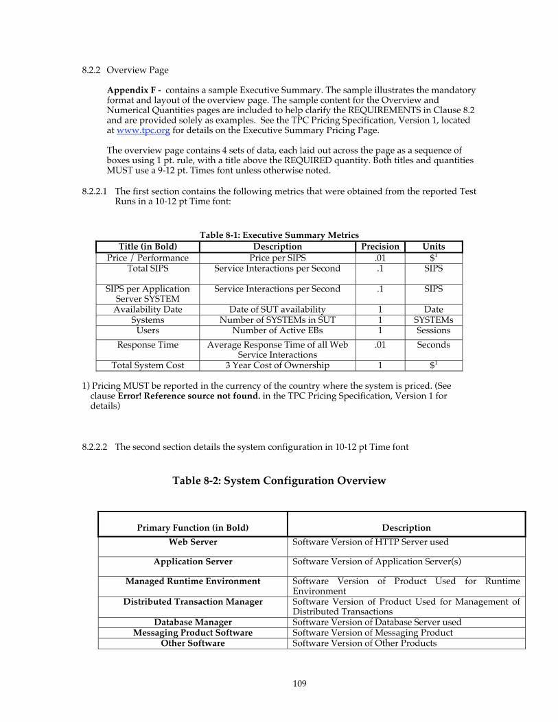
109
8.2.2 Overview Page
Appendix F - contains a sample Executive Summary. The sample illustrates the mandatory format and layout of the overview page. The sample content for the Overview and Numerical Quantities pages are included to help clarify the REQUIREMENTS in Clause 8.2 and are provided solely as examples. See the TPC Pricing Specification, Version 1, located at www.tpc.org for details on the Executive Summary Pricing Page.
The overview page contains 4 sets of data, each laid out across the page as a sequence of boxes using 1 pt. rule, with a title above the REQUIRED quantity. Both titles and quantities MUST use a 9-12 pt. Times font unless otherwise noted.
8.2.2.1 The first section contains the following metrics that were obtained from the reported Test Runs in a 10-12 pt Time font:
Table 8-1: Executive Summary Metrics
Title (in Bold) Description Precision Units Price / Performance Price per SIPS .01 $1
Total SIPS Service Interactions per Second .1 SIPS
SIPS per Application Server SYSTEM
Service Interactions per Second .1 SIPS
Availability Date Date of SUT availability 1 Date Systems Number of SYSTEMs in SUT 1 SYSTEMs
Users Number of Active EBs 1 Sessions
Response Time Average Response Time of all Web Service Interactions
.01 Seconds
Total System Cost 3 Year Cost of Ownership 1 $1 1) Pricing MUST be reported in the currency of the country where the system is priced. (See
clause Error! Reference source not found. in the TPC Pricing Specification, Version 1 for details)
8.2.2.2 The second section details the system configuration in 10-12 pt Time font
Table 8-2: System Configuration Overview
Primary Function (in Bold) Description
Web Server Software Version of HTTP Server used
Application Server Software Version of Application Server(s)
Managed Runtime Environment Software Version of Product Used for Runtime Environment
Distributed Transaction Manager Software Version of Product Used for Management of Distributed Transactions
Database Manager Software Version of Database Server used Messaging Product Software Software Version of Messaging Product
Other Software Software Version of Other Products

110
8.2.2.3 The third section contains a configuration diagram of the priced system. 8.2.2.4 The fourth and final section of the Implementation Overview contains a synopsis of the
SUT's major system components, including for each type of SYSTEM in the configuration: • SYSTEM's primary function as described in 8.2.2.2 (e.g. Database Server, Application
Server, both, Application Server, etc.); • System brand name and type (model) • OPERATING SYSTEM • Number and type of processors, speed (in MHz or GHz), number of cores, and number
of threads. • Physical memory size and types;
8.2.3 Pricing Page
Rules for reporting Pricing information are included in the current revision of the TPC Pricing Specification Version 1, located at www.tpc.org
8.2.4 Numerical Quantities Summary Page The Numerical Quantities Summary Page contains three sections used to summarize quantities in a concise manner. It is not intended to be an exhaustive collection of all reported numbers, but rather a high level overview of some of the more pertinent reported metrics.
8.2.4.1 The first section contains the SIPS Summary with the following information for each Web Service Interaction Type • Web Service Interaction Name • Web Service Interaction Rate in Interactions per Second • Mix Percentage • Average Response Time • 90th Percentile Response Time • Minimum response time • Maximum Response Time
The second section contains a graph of the measured throughput versus elapsed time
(i.e., wall clock time) for the entire Test Run. The x-axis represents the elapsed time from the start of the Test Run. The y-axis represents the throughput in Total SIPS. The maximum interval size MUST NOT exceed 30 seconds. A sample chart is shown in the sample Executive Summary in Appendix F - . The following information MUST be marked on the chart:
• Ramp-Up Period time end. • Stabilization Period end • The beginning and end of the Measurement Interval.
8.3 Clause 1 - Web Object and Logical Database Design
8.3.1 Listings MUST be provided for all table definition statements and all other statements used to set-up the database. Enough detail MUST be provided to replicate the database structures.
8.3.2 The physical organization of tables and indices, within the database, MUST be disclosed. When logical disk arrays (for example, RAID) are used, the mapping of database entities (for example, tables, views) MUST be specified. Additionally the mapping of logical units to physical disks MUST be disclosed.
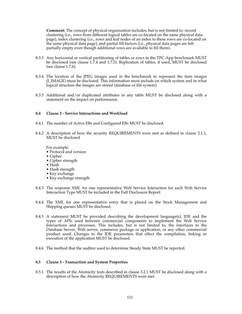
111
Comment: The concept of physical organization includes, but is not limited to: record clustering (i.e., rows from different logical tables are co-located on the same physical data page), index clustering (i.e., rows and leaf nodes of an index to these rows are co-located on the same physical data page), and partial fill-factors (i.e., physical data pages are left partially empty even though additional rows are available to fill them).
8.3.3 Any horizontal or vertical partitioning of tables or rows in the TPC-App benchmark MUST be disclosed (see clause 1.7.4 and 1.7.5). Replication of tables, if used, MUST be disclosed (see clause 1.7.6).
8.3.4 The location of the JPEG images used in the benchmark to represent the item images (I_IMAGE) must be disclosed. This information must include on which system and in what logical structure the images are stored (database or file system).
8.3.5 Additional and/or duplicated attributes in any table MUST be disclosed along with a statement on the impact on performance.
8.4 Clause 2 - Service Interactions and Workload
8.4.1 The number of Active EBs and Configured EBs MUST be disclosed.
8.4.2 A description of how the security REQUIREMENTS were met as defined in clause 2.1.1, MUST be disclosed
For example: • Protocol and version • Cipher • Cipher strength • Hash • Hash strength • Key exchange • Key exchange strength
8.4.3 The response XML for one representative Web Service Interaction for each Web Service Interaction Type MUST be included in the Full Disclosure Report
8.4.4 The XML for one representative entry that is placed on the Stock Management and Shipping queues MUST be disclosed.
8.4.5 A statement MUST be provided describing the development language(s), IDE and the types of APIs used between commercial components to implement the Web Service Interactions and processes. This includes, but is not limited to, the interfaces to the Database Server, Web server, commerce package or application, or any other commercial product used. Changes to the IDE parameters that effect the compilation, linking or execution of the application MUST be disclosed.
8.4.6 The method that the auditor used to determine Steady State MUST be reported.
8.5 Clause 3 - Transaction and System Properties
8.5.1 The results of the Atomicity tests described in clause 3.2.1 MUST be disclosed along with a description of how the Atomicity REQUIREMENTS were met.

112
8.5.2 The results of the Consistency tests described in clause 3.3.5 MUST be disclosed along with a description of how the Consistency REQUIREMENTS were met.
8.5.3 The results of the Isolation tests described in clause 3.4 MUST be disclosed along with a description of how the Isolation REQUIREMENTS were met.
8.5.4 The results of the Durability tests described in clause 3.5 MUST be disclosed along with a description of how the Durability REQUIREMENTS were met.
Comment: The order of the tests MUST be disclosed. Additionally, if any tests were combined, how they were combined MUST be disclosed.
8.6 Clause 4 - Scaling and Database Population
8.6.1 The cardinality (e.g., number of rows) of each table, as initially populated (see clause 4.2 & 4.3), MUST be disclosed.
8.6.2 The space REQUIRED to sustain 60 days of the reported throughput as defined in clause 4.4 MUST be disclosed.
8.6.3 The space REQUIRED for 8 hours of log space as defined in clause 4.5 MUST be disclosed. This includes but is not limited to the following logs: • Web Server • Stock Management Process • Database log • Messaging Product Log • Distributed Transaction Manager Log
8.6.4 The method for distributing persistent data and log data across all media MUST be described. A detailed diagram or listing of database files indicating the disks or volumes on which they reside MUST be included. Simple diagrams can be used for clarification. The data structures to which this clause refers include but are not limited to:
• Web Server • Database Tables • Database log • Distributed Transaction Manager log (if any) see clause 1.2.14 • Messaging Product persistant storage • Messaging Product log (if any) see clause 1.2.16
Comment: Detailed diagrams for layout of database files on disks can widely vary, and it is
difficult to provide exact guideline suitable for all implementations. The intent is to provide sufficient detail to allow independent reconstruction of the test database and access logs.
8.6.5 The method used by the auditor to verify that the database population meets the REQUIREMENTS in clauses 4.7 (table population) MUST be disclosed. This could include code reviews of the loader as well as SQL scripts run by the auditor to determine database validity. This description SHOULD be provided by the auditor.
8.7 Clause 5 Performance Metrics and Response Times
8.7.1 The Total SIPS, SIPS per Application Server SYSTEM, and price per SIPS MUST be disclosed.

113
8.7.2 The duration of the Ramp-Up Period, Stabilization Period, Steady State Period, and Measurement Interval MUST be disclosed. Additionally the auditor method used for determining the beginning of Steady State must be disclosed (see clause 5.4.3.1).
8.7.3 The minimum and maximum mix percentages for each Web Service Interaction Type across all Application Server SYSTEMs MUST be reported in tabular form. An example table is shown below:
Web Service Minimum
Mix Percentage
Maximum Mix
Percentage New Customer .96% 1.04%
Change Payment Method
4.97% 5.09%
Create Order 48.70% 52.16% Order Status 4.98% 5.07%
New Products List 6.94% 7.03% Product Detail 29.86% 30.12% Change Item 1.94% 2.09%
8.7.4 A list of the start times and durations of all checkpoints that complete between the start of the Test Run and the end of the Measurement Interval MUST be reported.
Comment: Some Database Server products do not use checkpoints as described in clause
5.4.5. If the Database Server product in use does not use the checkpoint mechanism then the method used to meet the REQUIREMENTS in clause 5.4.5.2 MUST be disclosed.
8.7.5 The percentage of Web Service Requests to the Create Order Web Service that contained a change of address as part of the input MUST be reported.
8.7.6 The number of Business Sessions that began within the Measurement Interval MUST be reported.
8.7.7 The method used to comply with clause 2.1.12 MUST be disclosed. If the SUT is not architected to guarantee that orders are shipped by the same Application Server SYSTEM that created the order then the following metrics MUST be disclosed:
• The highest number of orders shipped during the Measurement Interval on any Application Server SYSTEM in the SUT.
• The lowest number of orders shipped during the Measurement Interval on any Application Server SYSTEM in the SUT.
8.7.8 The number of requests logged in the ICE log within the Measurement Interval MUST be reported.
8.7.9 The percentage of New Customer Web Service Requests that chose “PO” as the payment method within the Measurement Interval MUST be reported (see clause 5.5).
8.7.10 The percentage of Change Payment Web Service Requests that specify “PO” as the payment method within the Measurement Interval MUST be reported (see clause 5.5)
8.7.11 The percentage of Create Order Web Service Requests that included a shipping address change within the Measurement Interval MUST be reported (see clause 5.5).
114
8.7.12 The percentage of orders submitted to the Create Order Web Service Interaction that resulted in a backorder within the Measurement Interval MUST be reported (see clause 5.5).
8.7.13 The average number of Service Interactions in a Business Session within the Measurement Interval MUST be reported.
8.7.14 Performance Statistics
8.7.14.1 The monitoring tools used during the Measurement Interval MUST be described and the operational methods invoked MUST be reported. For example, the monitor was invoked as a started task, and binary data was recorded every 15 seconds to a disk for post-processing.
8.7.14.2 If a sampling technique is used to obtain performance data then the sample rate (per second) MUST be reported. The data collection sampling interval MUST be configured to be at most 1 second. Comment 1: The intent of this clause is to report the sample rate for non-event-driven system monitor facilities. An example of this sample rate is found in determining "channelbusy", where the status of the channel MUST be sampled in order to determine if the resource is indeed busy. If the system monitoring facility is an event counter, it is not sampling.
Comment 2: It is understood that some sampling and performance counter tools
occasionally omit some samples from the performance log(s). It is left to the discretion of the auditor whether the collection of samples is sufficient to accurately portray the data that is reported.
8.7.14.3 If there is no relevance or meaning to a specific performance statistic for the system and products used in this specific benchmark implementation, then the symbol (N/A) for not applicable MAY be used. This exclusion MUST NOT be taken advantage of in order to avoid REQUIRED reporting.
8.7.14.4 The following performance statistics MUST be collected and reported for both application server SYSTEM(s) and the database server SYSTEM(s). Refer to the table in Appendix F - for specific details of reporting layouts and accuracy. For Clustered results, it is permissible to disclose one set of the following REQUIREMENTS for SYSTEM(s) that perform identical functions. In this case, the statistics reported MUST be for the SYSTEM with the highest average processor utilization.
8.7.14.4.1 Processor Utilization A key parameter of any capacity measurement is processor utilization. All enterprise-
class system monitoring facilities provide a means of recording processor utilization.
8.7.14.4.1.1 The REQUIRED reporting method is to record processor utilization, i.e. the percentage of time for which the processor was busy. This is the aggregate of all processors for this SYSTEM.
8.7.14.4.1.2 For the Measurement Interval, a graph illustrating processor utilization for each system MUST be reported. The x-axis represents the elapsed time from the start of the Measurement Interval. The y-axis represents the processor utilization on a scale of 0 to 100%. Discrete one minute intervals MUST be graphed across the Measurement Interval, where each value is the system's average processor utilization over that one minute interval.
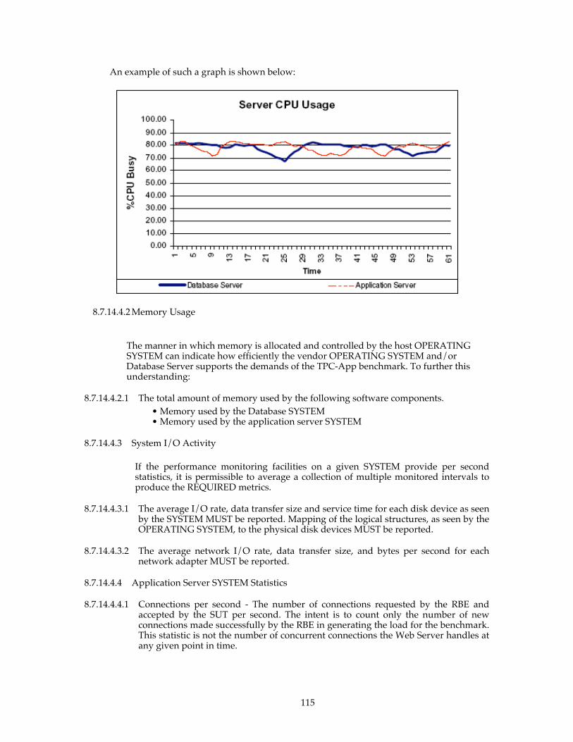
115
An example of such a graph is shown below:
8.7.14.4.2 Memory Usage
The manner in which memory is allocated and controlled by the host OPERATING SYSTEM can indicate how efficiently the vendor OPERATING SYSTEM and/or Database Server supports the demands of the TPC-App benchmark. To further this understanding:
8.7.14.4.2.1 The total amount of memory used by the following software components. • Memory used by the Database SYSTEM • Memory used by the application server SYSTEM
8.7.14.4.3 System I/O Activity
If the performance monitoring facilities on a given SYSTEM provide per second statistics, it is permissible to average a collection of multiple monitored intervals to produce the REQUIRED metrics.
8.7.14.4.3.1 The average I/O rate, data transfer size and service time for each disk device as seen by the SYSTEM MUST be reported. Mapping of the logical structures, as seen by the OPERATING SYSTEM, to the physical disk devices MUST be reported.
8.7.14.4.3.2 The average network I/O rate, data transfer size, and bytes per second for each network adapter MUST be reported.
8.7.14.4.4 Application Server SYSTEM Statistics
8.7.14.4.4.1 Connections per second - The number of connections requested by the RBE and accepted by the SUT per second. The intent is to count only the number of new connections made successfully by the RBE in generating the load for the benchmark. This statistic is not the number of concurrent connections the Web Server handles at any given point in time.

116
8.7.14.4.4.2 Connections per second - The number of connections requested by the SUT to the external emulators (PGE,ICE,SNE, POV).
Comment: It is not necessary to separate these counts by emulator type. It is permissible to collect this rate from the emulators themselves.
8.7.14.4.4.3 HTTPS requests per second from the RBE to the SUT and from the SUT to the external emulators (PGE, POV,SNE, ICE)
8.7.15 The monitored metrics MUST be reported in a table or tables similar to the following example:
Metric Application Server SYSTEM Database Server SYSTEM
% Processor Busy
Memory in use (visible to OS)
Disk I/O Rate (per device)
Avg Disk Utilization
Avg Disk Service time
Avg Disk I/O Block Size
Total Logging I/O Rate
Additional data rows for other metrics
A careful definition of the data fields reported MUST be provided to allow the data to be understood and properly interpreted.
8.7.16 The sponsor MUST disclose the maximum RETRY_COUNT that occurred during the Test Run
8.7.17 The sponsor MUST disclose information on all HTTP status codes for all HTTP requests to the SUT that occurred during the Measurement Interval. HTTP status codes with a count of zero may be omitted. The following HTTP status information MUST be disclosed in a tabular form for each returned HTTP status code:
• HTTP Status Code • Count
HTTP Status Count
200 720000 404 20 501 5

117
Comment: This information SHOULD be obtained from the application server HTTP log.
8.8 Clause 6 - SUT, RBE and Network
8.8.1 The rated bandwidth of the network(s) component used in the measured configuration MUST be disclosed along with any setting restricting that bandwidth. This includes, but is not limited to, the inter-node connections within the SUT, between the SUT and the RBE, and between the SUT and the PGE, POV, SNE, and ICE.
8.8.2 If the configuration REQUIRES operator intervention to meet the REQUIREMENTS of performance levels and uninterrupted operations, the mechanism and the frequency of this intervention MUST be disclosed.
8.8.3 A count, by Web Service Interaction Type, of the retries that occurred during the Measurement Interval MUST be disclosed. (See clause0)
8.8.4 The RBE method of generating the start seeds for the EBs MUST be disclosed. It MUST be clear that the start seeds are different for each EB. Additionally it MUST be clear that the start seeds are different from Test Run to Test Run.
Comment: It is the intent of this clause to prevent generating duplicate start seeds that will result in a reduction of inserts to the database (for example, ADDRESS table).
8.8.5 The number of random number generators used for each EB MUST be disclosed along with their purpose(s). Examples of purposes include: choosing the next Web Service Interaction, building random text strings, deciding whether the shipping address is changed, etc…
8.9 Clause 7 - Pricing Rules for reporting Pricing information are included in the current revision of the TPC Pricing Specification Version 1, located at www.tpc.org
8.10 Clause 9 - Audit Related Items
8.10.1 The auditor's name, address, phone number and e-mail address MUST be included in the Full Disclosure Report.
8.10.2 A copy of the auditor's attestation letter indicating the auditor's opinion of compliance MUST be included in the Full Disclosure Report.
8.11 Availability of the Full Disclosure Report
8.11.1 The Full Disclosure Report MUST be submitted to the TPC for publication on the TPC Website prior to the results being made public.
118
8.11.2 The Application Program, data generator, database loader program, database creation scripts, Application Program WSDL(s), and the WS-I test result file(s) MUST be included in an accessible zip or tar file. Additionally, all input required to generate the application program must be disclosed in a text file included in the zip or tar file. This file MUST be included with the submission to the TPC for availability on the results page.
8.11.3 The official full disclosure report MUST be available in English but MAY be translated to additional languages.
8.12 Revisions to the Full Disclosure Report
Rules for revision to the Full Disclosure Report as a result of changes in pricing, availability, or components of the Priced Configuration are defined in the TPC Pricing Specification, Version 1, located at www.tpc.org.
8.12.1 Substitution Requirements Rules for subtitution are included in the TPC Pricing Specification, Version 1, located at
www.tpc.org. Components which may be substituted for TPC-App are as follows:
8.12.1.1 All substitutions MUST be fully supported products. Additionally Hardware or Software product substitutions within the Priced Configuration, with the exceptions noted below require the benchmark to be re-run with the new components in order to re-establish compliance. The exceptions are:
• Secondary components such as switches, hubs, terminators and the like MAY be substituted. The connectivity capability of the substituted item MUST be greater than or equal to the original item. The substitute MUST be demonstrated to be at least equivalent to the original in performance. The performance tests and data used to demonstrate equal or greater performance MUST be disclosed.
• Disks MAY be substituted only under the following conditions: •To substitute disk drives, the previous drives used in the SUT MUST have
the same interface type and no longer be available from the original source. The substituted drives track to track seek time, interface speed, on disk buffer size, rotational speed, and media density MUST be the same or better.
•The number of new drives substituted for drives that are no longer available, MUST be greater than or equal to the number of drives in the published result. Additionally, there MUST be sufficient physical connectivity to attach the new drives.
• Disk HBA’s and external disk controllers MAY be substituted if the following conditions are met:
• The interface type MUST be the same (SCSI, Fibre Channel etc) • The speed of the interface MUST be the same or greater. • The connectivity capacity MUST be the same or greater. • The disk drive addressing capability MUST be the same or better. • The memory characteristics MUST be the same or better • The feature set of functions provided MUST be the same or better. • The performance MUST be the same or better.
• Software patches for any Commercially Available product MUST be for the same major and minor revision level. The cumulative effect of all patches MUST NOT degrade performance by more than 2%
• Memory substitution is allowed under the following conditions: •The same memory technology is used (PC100,PC133,DDR,RAMBUS,
etc) •The memory latency specifications are at least as good of better
119
•The memory capacity does not decrease •The number of memory modules in the system does not decrease •The memory has the same or better error checking capabilities •The memory has the same or better error correcting capabilities.
• No substitutions will be made for the following components: •Processor •Network Interface Card
Comment 1: The intent is to allow substitutions when the change would produce performance at least equivalent to the reported Total SIPS. The auditor MAY require additional tests to be run if the proof by documentation is not considered adequate. The auditor's letter of attestation MUST be attached to the revised full disclosure report. Comment 2: Substitution of any other component not specified above is not allowed. Comment 3: The component substitution will be open to challenge for a 60 day period. Comment 4:Patches to the application are not permitted.
8.12.1.2 Full Disclosure Report revisions MAY be REQUIRED for other reasons according to TPC policies (see TPC Policy Document).
8.12.1.3 The revised report MUST be submitted as defined in clause 8.11.
Clause 9 - Clause 9 - Auditing
9.1 Independent Audit
An independent audit of the benchmark results by an auditor certified by the TPC is REQUIRED. The current audit checklist MAY be obtained from one of the TPC certified auditors. The term "independent" is defined as: "the outcome of the benchmark carries no financial benefit to the auditing agency other than fees earned directly related to the audit." In addition, the auditing agency MUST NOT have supplied any performance consulting under contract for the benchmark under audit. The term "certified" is defined as: "the TPC has reviewed the qualification of the auditor and certified that the auditor is capable of verifying compliance of the benchmark result." Please see the TPC Audit Policy for a detailed description of the auditor certification process.
In addition, the following conditions MUST be met:
1. The auditing agency MUST NOT be financially related to the sponsor. For example, the auditing agency is financially related if it is a dependent division, the majority of its stock is owned by the sponsor, etc.
2. The auditing agency MUST NOT be financially related to any one of the suppliers of the measured/priced components, e.g., the Database Server supplier, Application Server vendor, etc.
9.1.1 The auditor's attestation letter MUST be made readily available to the public as part of the Full Disclosure Report, but a detailed report from the auditor is NOT REQUIRED.
The auditor MUST keep the checklist for any publication for the entire 60-day challenge period. This checklist MUST be available to any of the parties involved in a challenge during that period.

120
9.1.2 The auditor MAY require more tests for compliancy with the specification than are explicitly called for in this specification. However, the auditor SHOULD NOT test for attributes of the SUT that are NOT REQUIRED by this specification.
9.1.3 The Auditor MAY require the sponsor to demonstrate that the Web Service Request and Web Service Response messages contain the correct SOAP and/or XML Input and Output REQUIREMENTS for the Web Service Interactions, and that the content is properly formed. This could be performed by an instrumented RBE which records the requests and responses to a log. To verify correct behavior, the auditor MAY query the database to verify the content. The auditor MUST NOT require this demonstration during the Test Run.
9.1.4 In the case of audited TPC-App results, which are used as a basis for new TPC-App results, the sponsor of the new benchmark can claim that the results were audited if, and only if:
1. The auditor ensures that the hardware and software products are the same.
2. The application code remains the same.
3. The auditor reviews the Executive Summary of the new results and ensures that it matches what was contained in the original sponsor's Executive Summary.
4. The auditor can attest to Clauses 9.2.8.
The auditor is NOT REQUIRED to follow any of the remaining auditor's check list items from clause 9.2.
9.2 Auditors Checklist
9.2.1 Clause 1 - Logical Database Design
9.2.1.1 Verify that the specified tables, rows and columns exist and conform to the REQUIRED population and scaling.
9.2.1.2 Verify that the row identifiers are not disk or file offsets and that the Application Program does not access row(s) by physical location or offsets.
9.2.1.3 Verify that any additions to the tables attributes are disclosed
9.2.1.4 Verify that all tables support retrievals, updates, inserts and deletes.
9.2.1.5 Verify that all tables can support a growth of 5% additional rows.
9.2.1.6 Verify whether any replication of tables has been used, and if so, that it complies with the Atomicity, Consistency, and Isolation REQUIREMENTS of clause 1.7.6
9.2.1.7 Verify that each column is logically discrete and independently accessible.
9.2.1.8 Verify that the duplicate primary keys are detected and disallowed.
9.2.1.9 Verify that any row or column can be updated with the same semantics and syntax.
9.2.2 Clause 2 – Web Service Interactions
121
9.2.2.1 Verify that all Web Service Interactions are compliant with the security REQUIREMENTS of clause 0.
9.2.2.2 Verify that the SOAP messages for all requests are parsed on the SUT with a Commercially Available product.
9.2.2.3 Verify that the SOAP response messages from the SUT to the RBE are encoded using a Commercially Available product.
9.2.2.4 Verify that all XML serialization and deserialization on the SUT be done with a Commercially Available product.
9.2.2.5 Verify that connection management is compliant with clauses 2.1.17, 2.1.21 and 2.1.23.
9.2.2.6 Verify that a single Application Server SYSTEM is capable of handling the Web Service Interactions and the Durable Message operations.
9.2.2.7 Verify that a Commercially Available Messagin Product is used for handling the Durable Messages.
9.2.2.8 Verify that the RBE generates Web Service Requests that meet all input REQUIREMENTS.
9.2.2.9 Verify that the SUT produces responses to Web Service Requests as specified.
9.2.2.10 Verify that each EB uses at least one random number generator and that random number generators are not shared between Active EBs.
9.2.2.11 Verify that the random number generation method used by the EBs and SUT is the one specified in Appendix A.1.
9.2.2.12 Verify that the random number seeds used by the EBs and SUT are unique and in compliance with clause 2.1.34 and clause 2.1.35.
9.2.2.13 Verify that the test sponsor synchronized the systems in the SUT per clause 2.1.37.
9.2.2.14 Verify that the New Customer Web service is implemented as specified.
9.2.2.15 Verify that the Change Payment Method Web service is implemented as specified.
9.2.2.16 Verify that the Create Order Web service is implemented as specified.
9.2.2.17 Verify that the Shipping process is implemented as specified.
9.2.2.18 Verify that the Stock Management Process is implemented as specified.
9.2.2.19 Verify that the Order Status Web service is implemented as specified.
9.2.2.20 Verify that the New Products Web service is implemented as specified.
9.2.2.21 Verify that the Product Detail Web service is implemented as specified.
9.2.2.22 Verify that the Change Item Web service is implemented as specified.
9.2.2.23 Verify that the Web Server Access Log meets the collection and formatting REQUIREMENTS.
122
9.2.3 Clause 3 –Transaction and System Properties
9.2.3.1 Verify that all mechanisms needed to enforce the ACID properties REQUIRED by the benchmark were enabled throughout the Test Run and ACID tests.
9.2.3.2 Verify that all atomicity tests were performed and completed successfully.
9.2.3.3 Verify that the database is compliant with all of the consistency REQUIREMENTS.
9.2.3.4 Verify that all isolation tests were performed and completed successfully.
9.2.3.5 Verify that the durability test was performed and completed successfully for each component of the SUT REQUIRED in clause 3.5.3.
9.2.3.6 Verify that the durability test for the Messaging Product and Distributed Transaction Manager completed successfully.
9.2.4 Clause 4 – Scaling and Database Population
9.2.4.1 Validate that the initial cardinality of the database tables is compliant.
9.2.4.2 Verify that the initial database population is compliant.
9.2.4.3 Verify that the database load utility uses the REQUIRED random number generator.
9.2.4.4 Validate that the images used are compliant with clause 1.6
9.2.4.5 Validate the 60-day space calculations for database growth.
9.2.4.6 Validate that the 8-hour space calculations for the Web server access log(s), Distributed Transaction Manager Log, Message Product Log, and database log is compliant.
9.2.5 Clause 5 – Performance Metrics and Response Time
9.2.5.1 Validate that all Active EBs are active and submitting requests throughout the Stabilization and Steady State Periods.
9.2.5.2 Verify that the RETRY requirements of clause 0 were met.
9.2.5.3 Verify that the mix of Web Service Requests satisfies the REQUIRED mix during the Measurement Interval.
9.2.5.4 Verify the differences in the mix for each Application server SYSTEM varies by no more than the allowed tolerances (see Clause 5.5).
9.2.5.5 Verify that the SIRT’s reported during the Measurement Interval meet the response time constraints.
9.2.5.6 Verify the validity of the method used to accurately measure and report the Service Interaction Response Time (SIRT) at the RBE.
9.2.5.7 Verify that the reported throughput rating is computed correctly.
9.2.5.8 Verify that the Test Run meets all of the REQUIREMENTS in clause 5.4.
9.2.5.9 Verify that the Measurement Interval meets all of the REQUIREMENTS in clause 5.5.

123
9.2.5.10 Identify the point in the Test Run at which Steady State was achieved (see clause 5.4.1).
9.2.6 Clause 6 – SUT, Driver and Communications
9.2.6.1 Verify the RBE is performing as specified.
9.2.6.2 Verify that the REQUIRED communication protocol and encryption level is used between the RBE, SUT, and external emulators (POV, PGE, ICE).
9.2.6.3 Verify that each Business Session opens and uses its own socket connection(s) to the SUT instead of sharing a socket with another Business Session or reusing an existing socket.
9.2.6.4 Verify that each Business Session successfully uses SSL/TLS as per clause 2.1.13.
9.2.6.5 Verify that the backordered Create Order requests generated by the EB are correctly reflected in the ICE log.
9.2.6.6 Verify that the restrictions placed on the activity of the SUT are met (see clause 6.5.3).
9.2.6.7 Verify that the SUT meets the resource growth REQUIREMENTS defined in clause 6.12.
9.2.6.8 Verify that the SUT meets the non-disruptive maintenance REQUIREMENTS defined in clause 6.12.2. If the auditor feels it is sufficient, documentation can be used to meet this requirement.
9.2.6.9 Verify that the network configuration documented in the FDR matches the tested network configuration.
9.2.6.10 Verify that the RBE drives the SUT in a compliant manner.
9.2.6.11 Verify that the RBE generates compliant Business Session Lengths.
9.2.6.12 Verify that the SUT components are compliant with clause 6.5.1.
9.2.6.13 Verify the functions of the SUT comply with clause 6.5.2
9.2.6.14 Verify the SUT complies with the restrictions defined in clause 6.5.3.
9.2.6.15 Verify that the POV is compliant with clause 6.6
9.2.6.16 Verify that the PGE is compliant with clause 6.7.
9.2.6.17 Verify that the ICE is compliant with clause 6.8.
9.2.6.18 The auditor MUST verify successful ICE processing by reviewing a sample of the ICE log compared to orders with OL_STATUS of BACK_ORDERED in the Measurement Interval. Note, this does not need to contain all orders in the Measurement Interval.
9.2.6.19 Verify that the Web Service protocols used are conformant with the WS-I Basic Profile 1.0.
9.2.7 Clause 7 – Pricing
9.2.7.1 Rules for auditing Pricing information are included in the current revision of the TPC Pricing Specification Version 1, located at www.tpc.org
124
9.2.8 Clause 8 – FDR
Verify that the Full Disclosure Report is complete and accurate. Auditors can limit their review of the FDR to the following sections:
• Executive Summary • System Configuration • Database population and space calculations • Sections that include the disclosure of measurement data. • Any other section that the auditor feels is appropriate.
Comment: The intent is to limit the review to something less than a line by line check while still providing for a reasonable assurance that the data is accurate.
9.2.8.1 Verify that number and type of processors, the number of cores and the number of threads used in the priced SUT and measured SUT are reported (see Clause 8.2.2.4).
9.2.8.2 Verify that the performance data collection complies with the sampling and counting REQUIREMENTS of clause 8.7.14.2.
125
Appendix A - RANDOM NUMBER GENERATOR
A.1 Random Number Generator - 64bit Linear Congruential Method
The code provide on the TPC-App website ( http://www.tpc.org/tpc_app ) MUST be used to generate random data for the data generator/loader program, the EBs, and the SUT. Both a Java and C# implementation of this code has been provided ( “Lcg64Rng.cs” and “Lcg64Rng.java” ).

126
Appendix B - References
B.1 [WS-I BP 1.0 Specification] Web Services Interoperability “Basic Profile 1.0 Specification”, K. Ballinger, D. Ehnebuske, M. Gudgin, M. Nottingham, P. Yendluri, 16 April, 2004 (See http://www.ws-i.org/Profiles/BasicProfile-1.0-2004-04-16.html)
B.2 [RFC 2616] Hypertext Transfer Protocol 1.1, R. Fielding, J. Gettys, J. Mogul, H. Frystyk, L. Masinter, P. Leach, T. Berners-Lee, June 1999 (See http://www.ietf.org/rfc/rfc2616.txt)
B.3 [RFC 791] Internet Protocol (IPv4), Jon Postel, September 1981 (See http://www.ietf.org/rfc/rfc0791.txt)
B.4 [RFC 2460] Internet Protocol Version 6, (IPv6), S. Deering, R. Hinden, December 1998 (See http://www.ietf.org/rfc/rfc2460.txt)
B.5 [RFC 793] Transmission Control Protocol, Jon Postel,September 1981 (See http://www.ietf.org/rfc/rfc0793.txt)
B.6 [RFC 2527] Internet X.509 Public Key Infrastructure Certificate Policy and Certification Practices Framework, S. Chokhani, W. Ford, March 1999 (See http://www.ietf.org/rfc/rfc2527.txt)
B.7 [RFC 2437] PKCS#1 RSA Cryptography Specification Version 2.0, B. Kaliski, J. Staddon, October 1998 (See http://www.ietf.org/rfc/rfc2437.txt)
B.8 [SSL] SSL Protocol Version 3.0, A. Freier, P. Karlton, P. Kocher, March 1996 (See http://home.netscape.com/eng/ssl3/ssl-toc.html)
B.9 [RFC 2246] Transport Layer Security, T. Dierks, C. Allen, January 1999 (See http://www.ietf.org/rfc/rfc2246.txt
B.10 [SOAP] Simple Object Access Protocol (SOAP) 1.1, D. Box, D. Ehnebuske, G. Kakivaya, A. Layman, N. Mendelsohn, H. Neilsen, S. Thatte, D. Winer, 8 May 2000 (See http://www.w3.org/TR/2000/NOTE-SOAP-20000508/)
B.11 [W3C XML Schema Recommendation] XML Schema Part 2: Datatypes, P. Biron, A. Malhotra, 2 May 2001 (See http://www.w3.org/TR/xmlschema-2/)
B.12 [OSI reference model] Information Processing Systems - OSI Reference Model - The Basic Model, OSI SIGCOM, 1994 (see http://www.acm.org/sigs/sigcomm/standards/iso_stds/OSI_MODEL/ISO_IEC_7498-1.TXT)
B.13 [ECMA-335] Standard ECMA-335 2nd Edition – Common Language Infrastructure Partitions I to V, December 2002, (See http://www.ecma-international.org/publications/files/ECMA-ST/Ecma-335.pdf)
B.14 [CLF]
Logging Control In W3C httpd, World Wide Web Consortium, ( See http://www.w3.org/Daemon/User/Config/Logging.html#common-logfile-format )

127
Appendix C - Cumulative Distribution Function
The following table prescribes the discrete Cumulative Distribution Function (CDF) that MUST be used by the Active EB to randomly generate a BSL. The range of the distribution is [1, 120] and its mean is approximately 40.5. The CDF table values are a discretization of a Beta distribution with range [0, 120] and shape parameters 1.5 and 3.0. The table values were generated using Microsoft® Excel 2000's BETADIST function. That is, for 1 BSL 120, the table entry Cumulative Probability = BETADIST( BSL, 1.5, 3.0, 0, 120). A tab delimited file with the table’s values can be obtained on the TPC Website at: http://www.tpc.org/tpc_app
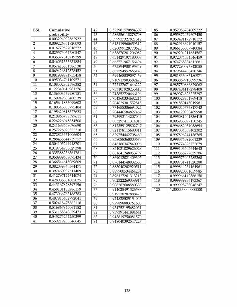
128
BSL Cumulative probability
1 0.003294992562922 2 0.009226351820093 3 0.016779527018572 4 0.025573064780547 5 0.035377310219299 6 0.046031555631884 7 0.057413851386530 8 0.069426812578452 9 0.081989894755458 10 0.095034761109571 11 0.108502302596382 12 0.122340616981276 13 0.136503579980181 14 0.150949800480539 15 0.165641835099602 16 0.180545583775404 17 0.195629815327623 18 0.210865788597611 19 0.226226945354508 20 0.241688658076690 21 0.257228020372218 22 0.272823671006604 23 0.288455644759757 24 0.304105244948701 25 0.319754933629398 26 0.335388236361781 27 0.350989659075434 28 0.366544615069809 29 0.382039360564471 30 0.397460937511409 31 0.412797122614074 32 0.428036381682025 33 0.443167828597196 34 0.458181188286159 35 0.473066763188783 36 0.487815402792041 37 0.502418475862118 38 0.516867845061182 39 0.531155843679473 40 0.545275254250299 41 0.559219288846645
42 0.572981570884307 43 0.586556118278708 44 0.599937327821512 45 0.613119960659312 46 0.626099128770628 47 0.638870281206082 48 0.651429197180008 49 0.663771967156494 50 0.675894988195849 51 0.687794952665143 52 0.699468839097459 53 0.710913903582423 54 0.722127671646222 55 0.733107928255413 56 0.743852720466196 57 0.754360334682216 58 0.764629301552815 59 0.774658386694024 60 0.784446584827467 61 0.793993114207044 62 0.803297411314016 63 0.812359125802747 64 0.821178115680811 65 0.829754442708460 66 0.838088368003678 67 0.846180347840096 68 0.854031029626028 69 0.861641248053797 70 0.869012021409305 71 0.876144548032555 72 0.883040202920511 73 0.889700534464284 74 0.896127261313213 75 0.902322269358916 76 0.908287608580333 77 0.914025491326588 78 0.919538287888426 79 0.924828525154045 80 0.929898883761605 81 0.934752195682031 82 0.939391441884641 83 0.943819750081570 84 0.948040392547227
85 0.952056784009222 86 0.955872479607450 87 0.959491172918172 88 0.962916694040157 89 0.966153007740084 90 0.969204211654587 91 0.972074534546459 92 0.974768334612681 93 0.977290097842055 94 0.979644436420346 95 0.981836087180971 96 0.983869910099336 97 0.985750886829062 98 0.987484119278408 99 0.989074828225297 100 0.990528351969418 101 0.991850145019981 102 0.993045776817743 103 0.994120930489998 104 0.995081401636415 105 0.995933097150345 106 0.996682034058694 107 0.997334338402302 108 0.997896244136765 109 0.998374092061239 110 0.998774328772679 111 0.999103505644643 112 0.999368277829786 113 0.999575403285268 114 0.999731741820280 115 0.999844254164961 116 0.999920001059985 117 0.999966142366158 118 0.999989936193367 119 0.999998738048247 120 1.000000000000000
129
Appendix D - BSL Variate Sample Code
The following is sample code for generating the BSL variates from the BSL cumulative distribution function (CDF). The code available on the TPC-App website ( http://www.tpc.org/tpc_app ) MAY be used to implement how Active EBs generate BSL's. It is NOT REQUIRED that this code be used; it is being provided as a convenience. What is REQUIRED is that the Active EBs generation of BSL's conforms to the BSL CDF given in Appendix C - .
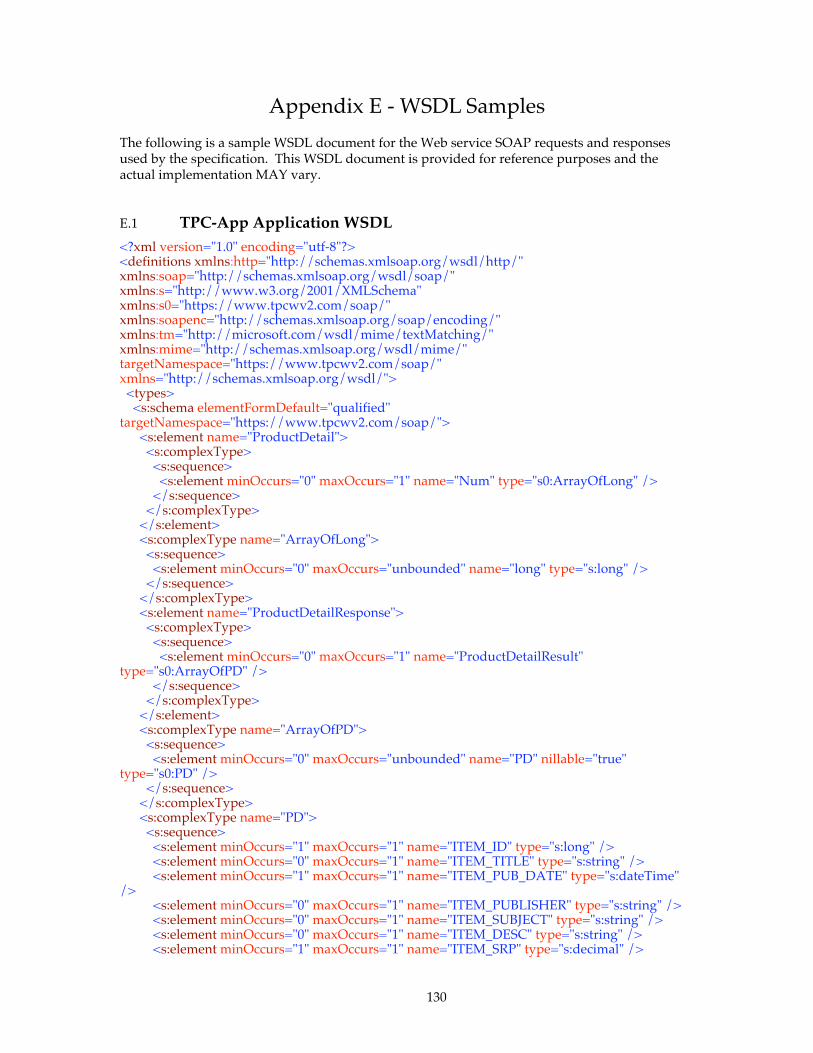
130
Appendix E - WSDL Samples
The following is a sample WSDL document for the Web service SOAP requests and responses used by the specification. This WSDL document is provided for reference purposes and the actual implementation MAY vary.
E.1 TPC-App Application WSDL <?xml version="1.0" encoding="utf-8"?> <definitions xmlns:http="http://schemas.xmlsoap.org/wsdl/http/" xmlns:soap="http://schemas.xmlsoap.org/wsdl/soap/" xmlns:s="http://www.w3.org/2001/XMLSchema" xmlns:s0="https://www.tpcwv2.com/soap/" xmlns:soapenc="http://schemas.xmlsoap.org/soap/encoding/" xmlns:tm="http://microsoft.com/wsdl/mime/textMatching/" xmlns:mime="http://schemas.xmlsoap.org/wsdl/mime/" targetNamespace="https://www.tpcwv2.com/soap/" xmlns="http://schemas.xmlsoap.org/wsdl/"> <types> <s:schema elementFormDefault="qualified" targetNamespace="https://www.tpcwv2.com/soap/"> <s:element name="ProductDetail"> <s:complexType> <s:sequence> <s:element minOccurs="0" maxOccurs="1" name="Num" type="s0:ArrayOfLong" /> </s:sequence> </s:complexType> </s:element> <s:complexType name="ArrayOfLong"> <s:sequence> <s:element minOccurs="0" maxOccurs="unbounded" name="long" type="s:long" /> </s:sequence> </s:complexType> <s:element name="ProductDetailResponse"> <s:complexType> <s:sequence> <s:element minOccurs="0" maxOccurs="1" name="ProductDetailResult" type="s0:ArrayOfPD" /> </s:sequence> </s:complexType> </s:element> <s:complexType name="ArrayOfPD"> <s:sequence> <s:element minOccurs="0" maxOccurs="unbounded" name="PD" nillable="true" type="s0:PD" /> </s:sequence> </s:complexType> <s:complexType name="PD"> <s:sequence> <s:element minOccurs="1" maxOccurs="1" name="ITEM_ID" type="s:long" /> <s:element minOccurs="0" maxOccurs="1" name="ITEM_TITLE" type="s:string" /> <s:element minOccurs="1" maxOccurs="1" name="ITEM_PUB_DATE" type="s:dateTime" /> <s:element minOccurs="0" maxOccurs="1" name="ITEM_PUBLISHER" type="s:string" /> <s:element minOccurs="0" maxOccurs="1" name="ITEM_SUBJECT" type="s:string" /> <s:element minOccurs="0" maxOccurs="1" name="ITEM_DESC" type="s:string" /> <s:element minOccurs="1" maxOccurs="1" name="ITEM_SRP" type="s:decimal" />
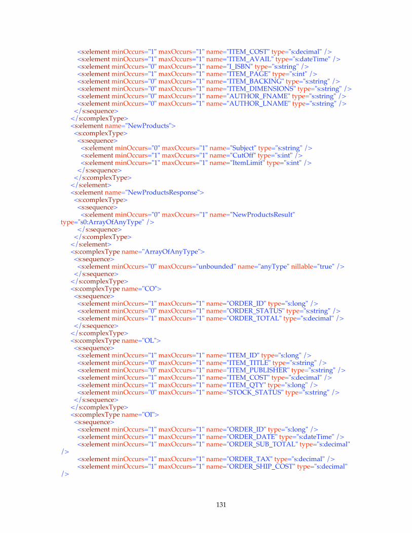
131
<s:element minOccurs="1" maxOccurs="1" name="ITEM_COST" type="s:decimal" /> <s:element minOccurs="1" maxOccurs="1" name="ITEM_AVAIL" type="s:dateTime" /> <s:element minOccurs="0" maxOccurs="1" name="I_ISBN" type="s:string" /> <s:element minOccurs="1" maxOccurs="1" name="ITEM_PAGE" type="s:int" /> <s:element minOccurs="0" maxOccurs="1" name="ITEM_BACKING" type="s:string" /> <s:element minOccurs="0" maxOccurs="1" name="ITEM_DIMENSIONS" type="s:string" /> <s:element minOccurs="0" maxOccurs="1" name="AUTHOR_FNAME" type="s:string" /> <s:element minOccurs="0" maxOccurs="1" name="AUTHOR_LNAME" type="s:string" /> </s:sequence> </s:complexType> <s:element name="NewProducts"> <s:complexType> <s:sequence> <s:element minOccurs="0" maxOccurs="1" name="Subject" type="s:string" /> <s:element minOccurs="1" maxOccurs="1" name="CutOff" type="s:int" /> <s:element minOccurs="1" maxOccurs="1" name="ItemLimit" type="s:int" /> </s:sequence> </s:complexType> </s:element> <s:element name="NewProductsResponse"> <s:complexType> <s:sequence> <s:element minOccurs="0" maxOccurs="1" name="NewProductsResult" type="s0:ArrayOfAnyType" /> </s:sequence> </s:complexType> </s:element> <s:complexType name="ArrayOfAnyType"> <s:sequence> <s:element minOccurs="0" maxOccurs="unbounded" name="anyType" nillable="true" /> </s:sequence> </s:complexType> <s:complexType name="CO"> <s:sequence> <s:element minOccurs="1" maxOccurs="1" name="ORDER_ID" type="s:long" /> <s:element minOccurs="0" maxOccurs="1" name="ORDER_STATUS" type="s:string" /> <s:element minOccurs="1" maxOccurs="1" name="ORDER_TOTAL" type="s:decimal" /> </s:sequence> </s:complexType> <s:complexType name="OL"> <s:sequence> <s:element minOccurs="1" maxOccurs="1" name="ITEM_ID" type="s:long" /> <s:element minOccurs="0" maxOccurs="1" name="ITEM_TITLE" type="s:string" /> <s:element minOccurs="0" maxOccurs="1" name="ITEM_PUBLISHER" type="s:string" /> <s:element minOccurs="1" maxOccurs="1" name="ITEM_COST" type="s:decimal" /> <s:element minOccurs="1" maxOccurs="1" name="ITEM_QTY" type="s:long" /> <s:element minOccurs="0" maxOccurs="1" name="STOCK_STATUS" type="s:string" /> </s:sequence> </s:complexType> <s:complexType name="OI"> <s:sequence> <s:element minOccurs="1" maxOccurs="1" name="ORDER_ID" type="s:long" /> <s:element minOccurs="1" maxOccurs="1" name="ORDER_DATE" type="s:dateTime" /> <s:element minOccurs="1" maxOccurs="1" name="ORDER_SUB_TOTAL" type="s:decimal" /> <s:element minOccurs="1" maxOccurs="1" name="ORDER_TAX" type="s:decimal" /> <s:element minOccurs="1" maxOccurs="1" name="ORDER_SHIP_COST" type="s:decimal" />
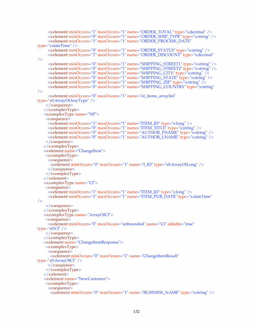
132
<s:element minOccurs="1" maxOccurs="1" name="ORDER_TOTAL" type="s:decimal" /> <s:element minOccurs="0" maxOccurs="1" name="ORDER_SHIP_TYPE" type="s:string" /> <s:element minOccurs="1" maxOccurs="1" name="ORDER_PROCESS_DATE" type="s:dateTime" /> <s:element minOccurs="0" maxOccurs="1" name="ORDER_STATUS" type="s:string" /> <s:element minOccurs="1" maxOccurs="1" name="ORDER_DISCOUNT" type="s:decimal" /> <s:element minOccurs="0" maxOccurs="1" name="SHIPPING_STREET1" type="s:string" /> <s:element minOccurs="0" maxOccurs="1" name="SHIPPING_STREET2" type="s:string" /> <s:element minOccurs="0" maxOccurs="1" name="SHIPPING_CITY" type="s:string" /> <s:element minOccurs="0" maxOccurs="1" name="SHIPPING_STATE" type="s:string" /> <s:element minOccurs="0" maxOccurs="1" name="SHIPPING_ZIP" type="s:string" /> <s:element minOccurs="0" maxOccurs="1" name="SHIPPING_COUNTRY" type="s:string" /> <s:element minOccurs="0" maxOccurs="1" name="ol_items_arraylist" type="s0:ArrayOfAnyType" /> </s:sequence> </s:complexType> <s:complexType name="NP"> <s:sequence> <s:element minOccurs="1" maxOccurs="1" name="ITEM_ID" type="s:long" /> <s:element minOccurs="0" maxOccurs="1" name="ITEM_TITLE" type="s:string" /> <s:element minOccurs="0" maxOccurs="1" name="AUTHOR_FNAME" type="s:string" /> <s:element minOccurs="0" maxOccurs="1" name="AUTHOR_LNAME" type="s:string" /> </s:sequence> </s:complexType> <s:element name="ChangeItem"> <s:complexType> <s:sequence> <s:element minOccurs="0" maxOccurs="1" name="I_ID" type="s0:ArrayOfLong" /> </s:sequence> </s:complexType> </s:element> <s:complexType name="CI"> <s:sequence> <s:element minOccurs="1" maxOccurs="1" name="ITEM_ID" type="s:long" /> <s:element minOccurs="1" maxOccurs="1" name="ITEM_PUB_DATE" type="s:dateTime" /> </s:sequence> </s:complexType> <s:complexType name="ArrayOfCI"> <s:sequence> <s:element minOccurs="0" maxOccurs="unbounded" name="CI" nillable="true" type="s0:CI" /> </s:sequence> </s:complexType> <s:element name="ChangeItemResponse"> <s:complexType> <s:sequence> <s:element minOccurs="0" maxOccurs="1" name="ChangeItemResult" type="s0:ArrayOfCI" /> </s:sequence> </s:complexType> </s:element> <s:element name="NewCustomer"> <s:complexType> <s:sequence> <s:element minOccurs="0" maxOccurs="1" name="BUSINESS_NAME" type="s:string" />

133
<s:element minOccurs="0" maxOccurs="1" name="BUSINESS_INFO" type="s:string" /> <s:element minOccurs="0" maxOccurs="1" name="PASSWORD" type="s:string" /> <s:element minOccurs="0" maxOccurs="1" name="CONTACT_F_NAME" type="s:string" /> <s:element minOccurs="0" maxOccurs="1" name="CONTACT_L_NAME" type="s:string" /> <s:element minOccurs="0" maxOccurs="1" name="CONTACT_PHONE" type="s:string" /> <s:element minOccurs="0" maxOccurs="1" name="CONTACT_EMAIL" type="s:string" /> <s:element minOccurs="0" maxOccurs="1" name="PAYMENT_METHOD" type="s:string" /> <s:element minOccurs="1" maxOccurs="1" name="PO_ID" type="s:long" /> <s:element minOccurs="0" maxOccurs="1" name="CREDIT_INFO" type="s:string" /> <s:element minOccurs="0" maxOccurs="1" name="BILLING_ADDR1" type="s:string" /> <s:element minOccurs="0" maxOccurs="1" name="BILLING_ADDR2" type="s:string" /> <s:element minOccurs="0" maxOccurs="1" name="BILLING_CITY" type="s:string" /> <s:element minOccurs="0" maxOccurs="1" name="BILLING_STATE" type="s:string" /> <s:element minOccurs="0" maxOccurs="1" name="BILLING_ZIP" type="s:string" /> <s:element minOccurs="0" maxOccurs="1" name="BILL_COUNTRY" type="s:string" /> </s:sequence> </s:complexType> </s:element> <s:element name="NewCustomerResponse"> <s:complexType> <s:sequence> <s:element minOccurs="1" maxOccurs="1" name="NewCustomerResult" type="s:long" /> </s:sequence> </s:complexType> </s:element> <s:element name="ChangePaymentMethod"> <s:complexType> <s:sequence> <s:element minOccurs="1" maxOccurs="1" name="C_ID" type="s:long" /> <s:element minOccurs="0" maxOccurs="1" name="PAYMENT_METHOD" type="s:string" /> <s:element minOccurs="0" maxOccurs="1" name="CREDIT_INFO" type="s:string" /> <s:element minOccurs="1" maxOccurs="1" name="PO_ID" type="s:long" /> </s:sequence> </s:complexType> </s:element> <s:element name="ChangePaymentMethodResponse"> <s:complexType> <s:sequence> <s:element minOccurs="0" maxOccurs="1" name="ChangePaymentMethodResult" type="s:string" /> </s:sequence> </s:complexType> </s:element> <s:element name="OrderStatus"> <s:complexType> <s:sequence> <s:element minOccurs="1" maxOccurs="1" name="CUSTOMER_ID" type="s:long" /> <s:element minOccurs="1" maxOccurs="1" name="ORDER_COUNT" type="s:int" /> <s:element minOccurs="0" maxOccurs="1" name="BUSINESS_NAME" type="s:string" /> <s:element minOccurs="0" maxOccurs="1" name="PASSWD" type="s:string" /> </s:sequence> </s:complexType> </s:element>

134
<s:complexType name="OS"> <s:sequence> <s:element minOccurs="0" maxOccurs="1" name="C_CONTACT_FNAME" type="s:string" /> <s:element minOccurs="0" maxOccurs="1" name="C_CONTACT_LNAME" type="s:string" /> <s:element minOccurs="0" maxOccurs="1" name="C_CONTACT_PHONE" type="s:string" /> <s:element minOccurs="0" maxOccurs="1" name="C_CONTACT_EMAIL" type="s:string" /> <s:element minOccurs="0" maxOccurs="1" name="BILLING_STREET1" type="s:string" /> <s:element minOccurs="0" maxOccurs="1" name="BILLING_STREET2" type="s:string" /> <s:element minOccurs="0" maxOccurs="1" name="BILLING_CITY" type="s:string" /> <s:element minOccurs="0" maxOccurs="1" name="BILLING_STATE" type="s:string" /> <s:element minOccurs="0" maxOccurs="1" name="BILLING_ZIP" type="s:string" /> <s:element minOccurs="0" maxOccurs="1" name="BILL_COUNTRY" type="s:string" /> <s:element minOccurs="0" maxOccurs="1" name="order_infos_arraylist" type="s0:ArrayOfAnyType" /> </s:sequence> </s:complexType> <s:element name="OrderStatusResponse"> <s:complexType> <s:sequence> <s:element minOccurs="0" maxOccurs="1" name="OrderStatusResult" type="s0:OS" /> </s:sequence> </s:complexType> </s:element> <s:element name="CreateOrder"> <s:complexType> <s:sequence> <s:element minOccurs="1" maxOccurs="1" name="CUSTOMER_ID" type="s:long" /> <s:element minOccurs="0" maxOccurs="1" name="ITEM_ID" type="s0:ArrayOfAnyType" /> <s:element minOccurs="0" maxOccurs="1" name="QTY" type="s0:ArrayOfAnyType" /> <s:element minOccurs="0" maxOccurs="1" name="SHIPPING_STREET1" type="s:string" /> <s:element minOccurs="0" maxOccurs="1" name="SHIPPING_STREET2" type="s:string" /> <s:element minOccurs="0" maxOccurs="1" name="SHIPPING_CITY" type="s:string" /> <s:element minOccurs="0" maxOccurs="1" name="SHIPPING_STATE" type="s:string" /> <s:element minOccurs="0" maxOccurs="1" name="SHIPPING_ZIP" type="s:string" /> <s:element minOccurs="0" maxOccurs="1" name="COUNTRY_NAME" type="s:string" /> <s:element minOccurs="0" maxOccurs="1" name="SHIPPING_TYPE" type="s:string" /> <s:element minOccurs="0" maxOccurs="1" name="CC_TYPE" type="s:string" /> <s:element minOccurs="0" maxOccurs="1" name="CC_NUMBER" type="s:string" /> <s:element minOccurs="1" maxOccurs="1" name="CC_EXPIRY" type="s:dateTime" /> <s:element minOccurs="0" maxOccurs="1" name="CC_NAME" type="s:string" /> </s:sequence> </s:complexType> </s:element> <s:element name="CreateOrderResponse"> <s:complexType> <s:sequence> <s:element minOccurs="0" maxOccurs="1" name="CreateOrderResult" type="s0:CO" /> </s:sequence> </s:complexType> </s:element> </s:schema>

135
</types> <message name="ProductDetailSoapIn"> <part name="parameters" element="s0:ProductDetail" /> </message> <message name="ProductDetailSoapOut"> <part name="parameters" element="s0:ProductDetailResponse" /> </message> <message name="NewProductsSoapIn"> <part name="parameters" element="s0:NewProducts" /> </message> <message name="NewProductsSoapOut"> <part name="parameters" element="s0:NewProductsResponse" /> </message> <message name="ChangeItemSoapIn"> <part name="parameters" element="s0:ChangeItem" /> </message> <message name="ChangeItemSoapOut"> <part name="parameters" element="s0:ChangeItemResponse" /> </message> <message name="NewCustomerSoapIn"> <part name="parameters" element="s0:NewCustomer" /> </message> <message name="NewCustomerSoapOut"> <part name="parameters" element="s0:NewCustomerResponse" /> </message> <message name="ChangePaymentMethodSoapIn"> <part name="parameters" element="s0:ChangePaymentMethod" /> </message> <message name="ChangePaymentMethodSoapOut"> <part name="parameters" element="s0:ChangePaymentMethodResponse" /> </message> <message name="OrderStatusSoapIn"> <part name="parameters" element="s0:OrderStatus" /> </message> <message name="OrderStatusSoapOut"> <part name="parameters" element="s0:OrderStatusResponse" /> </message> <message name="CreateOrderSoapIn"> <part name="parameters" element="s0:CreateOrder" /> </message> <message name="CreateOrderSoapOut"> <part name="parameters" element="s0:CreateOrderResponse" /> </message> <portType name="TPCWSoap"> <operation name="ProductDetail"> <input message="s0:ProductDetailSoapIn" /> <output message="s0:ProductDetailSoapOut" /> </operation> <operation name="NewProducts"> <input message="s0:NewProductsSoapIn" /> <output message="s0:NewProductsSoapOut" /> </operation> <operation name="ChangeItem"> <input message="s0:ChangeItemSoapIn" /> <output message="s0:ChangeItemSoapOut" /> </operation> <operation name="NewCustomer"> <input message="s0:NewCustomerSoapIn" />
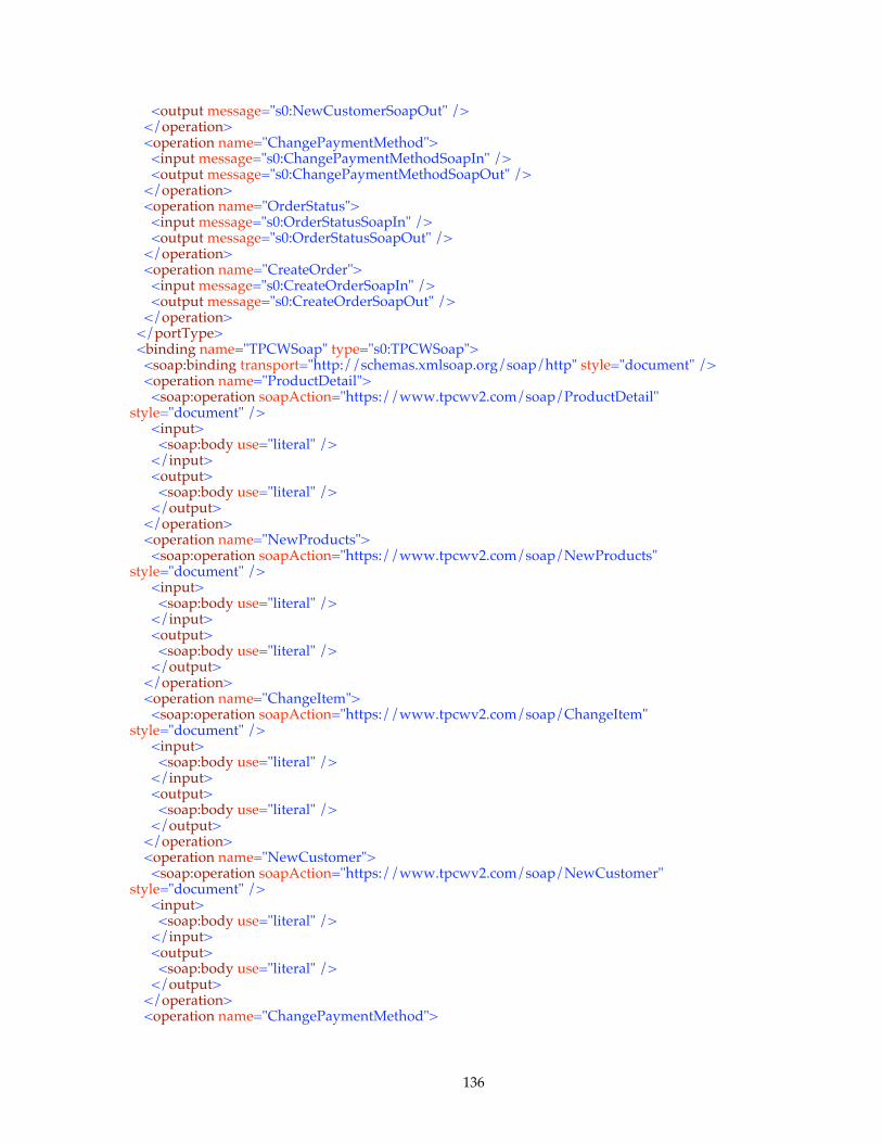
136
<output message="s0:NewCustomerSoapOut" /> </operation> <operation name="ChangePaymentMethod"> <input message="s0:ChangePaymentMethodSoapIn" /> <output message="s0:ChangePaymentMethodSoapOut" /> </operation> <operation name="OrderStatus"> <input message="s0:OrderStatusSoapIn" /> <output message="s0:OrderStatusSoapOut" /> </operation> <operation name="CreateOrder"> <input message="s0:CreateOrderSoapIn" /> <output message="s0:CreateOrderSoapOut" /> </operation> </portType> <binding name="TPCWSoap" type="s0:TPCWSoap"> <soap:binding transport="http://schemas.xmlsoap.org/soap/http" style="document" /> <operation name="ProductDetail"> <soap:operation soapAction="https://www.tpcwv2.com/soap/ProductDetail" style="document" /> <input> <soap:body use="literal" /> </input> <output> <soap:body use="literal" /> </output> </operation> <operation name="NewProducts"> <soap:operation soapAction="https://www.tpcwv2.com/soap/NewProducts" style="document" /> <input> <soap:body use="literal" /> </input> <output> <soap:body use="literal" /> </output> </operation> <operation name="ChangeItem"> <soap:operation soapAction="https://www.tpcwv2.com/soap/ChangeItem" style="document" /> <input> <soap:body use="literal" /> </input> <output> <soap:body use="literal" /> </output> </operation> <operation name="NewCustomer"> <soap:operation soapAction="https://www.tpcwv2.com/soap/NewCustomer" style="document" /> <input> <soap:body use="literal" /> </input> <output> <soap:body use="literal" /> </output> </operation> <operation name="ChangePaymentMethod">

137
<soap:operation soapAction="https://www.tpcwv2.com/soap/ChangePaymentMethod" style="document" /> <input> <soap:body use="literal" /> </input> <output> <soap:body use="literal" /> </output> </operation> <operation name="OrderStatus"> <soap:operation soapAction="https://www.tpcwv2.com/soap/OrderStatus" style="document" /> <input> <soap:body use="literal" /> </input> <output> <soap:body use="literal" /> </output> </operation> <operation name="CreateOrder"> <soap:operation soapAction="https://www.tpcwv2.com/soap/CreateOrder" style="document" /> <input> <soap:body use="literal" /> </input> <output> <soap:body use="literal" /> </output> </operation> </binding> <service name="TPCW"> <port name="TPCWSoap" binding="s0:TPCWSoap"> <soap:address location="http://www.tpcwv2.com/soap/tpcw.asmx" /> </port> </service>
</definitions>
E.2 POV WSDL <?xml version="1.0" encoding="utf-8"?> <definitions xmlns:http="http://schemas.xmlsoap.org/wsdl/http/" xmlns:soap="http://schemas.xmlsoap.org/wsdl/soap/" xmlns:s="http://www.w3.org/2001/XMLSchema" xmlns:s0="http://tempuri.org/" xmlns:soapenc="http://schemas.xmlsoap.org/soap/encoding/" xmlns:tm="http://microsoft.com/wsdl/mime/textMatching/" xmlns:mime="http://schemas.xmlsoap.org/wsdl/mime/" targetNamespace="http://tempuri.org/" xmlns="http://schemas.xmlsoap.org/wsdl/"> <types> <s:schema elementFormDefault="qualified" targetNamespace="http://tempuri.org/"> <s:element name="POV_Authorization"> <s:complexType> <s:sequence> <s:element minOccurs="1" maxOccurs="1" name="requestIn" type="s0:POV_Request" /> </s:sequence> </s:complexType> </s:element>
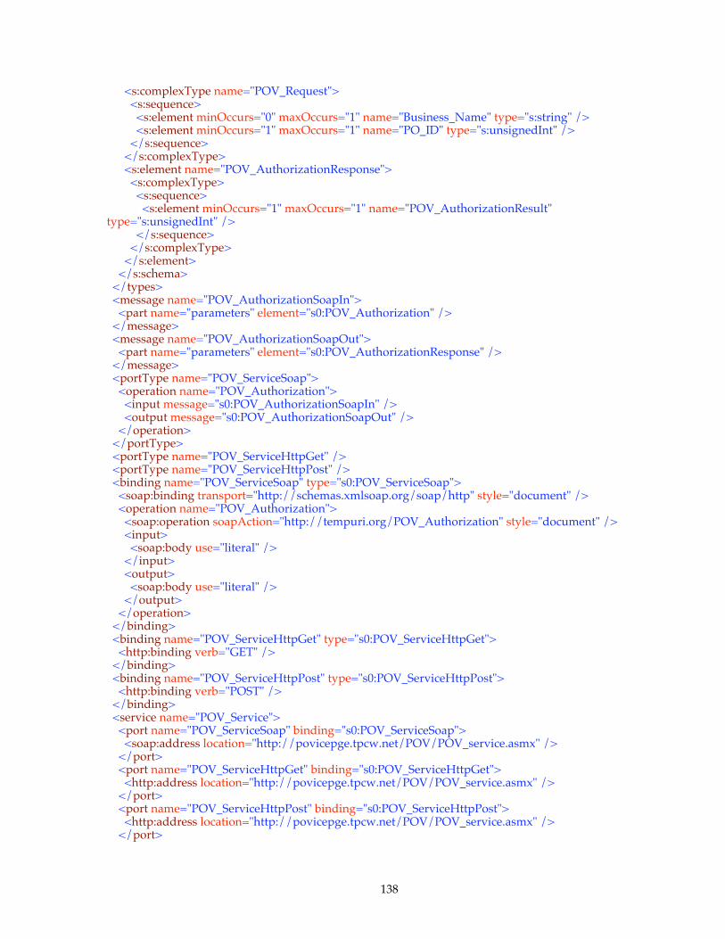
138
<s:complexType name="POV_Request"> <s:sequence> <s:element minOccurs="0" maxOccurs="1" name="Business_Name" type="s:string" /> <s:element minOccurs="1" maxOccurs="1" name="PO_ID" type="s:unsignedInt" /> </s:sequence> </s:complexType> <s:element name="POV_AuthorizationResponse"> <s:complexType> <s:sequence> <s:element minOccurs="1" maxOccurs="1" name="POV_AuthorizationResult" type="s:unsignedInt" /> </s:sequence> </s:complexType> </s:element> </s:schema> </types> <message name="POV_AuthorizationSoapIn"> <part name="parameters" element="s0:POV_Authorization" /> </message> <message name="POV_AuthorizationSoapOut"> <part name="parameters" element="s0:POV_AuthorizationResponse" /> </message> <portType name="POV_ServiceSoap"> <operation name="POV_Authorization"> <input message="s0:POV_AuthorizationSoapIn" /> <output message="s0:POV_AuthorizationSoapOut" /> </operation> </portType> <portType name="POV_ServiceHttpGet" /> <portType name="POV_ServiceHttpPost" /> <binding name="POV_ServiceSoap" type="s0:POV_ServiceSoap"> <soap:binding transport="http://schemas.xmlsoap.org/soap/http" style="document" /> <operation name="POV_Authorization"> <soap:operation soapAction="http://tempuri.org/POV_Authorization" style="document" /> <input> <soap:body use="literal" /> </input> <output> <soap:body use="literal" /> </output> </operation> </binding> <binding name="POV_ServiceHttpGet" type="s0:POV_ServiceHttpGet"> <http:binding verb="GET" /> </binding> <binding name="POV_ServiceHttpPost" type="s0:POV_ServiceHttpPost"> <http:binding verb="POST" /> </binding> <service name="POV_Service"> <port name="POV_ServiceSoap" binding="s0:POV_ServiceSoap"> <soap:address location="http://povicepge.tpcw.net/POV/POV_service.asmx" /> </port> <port name="POV_ServiceHttpGet" binding="s0:POV_ServiceHttpGet"> <http:address location="http://povicepge.tpcw.net/POV/POV_service.asmx" /> </port> <port name="POV_ServiceHttpPost" binding="s0:POV_ServiceHttpPost"> <http:address location="http://povicepge.tpcw.net/POV/POV_service.asmx" /> </port>
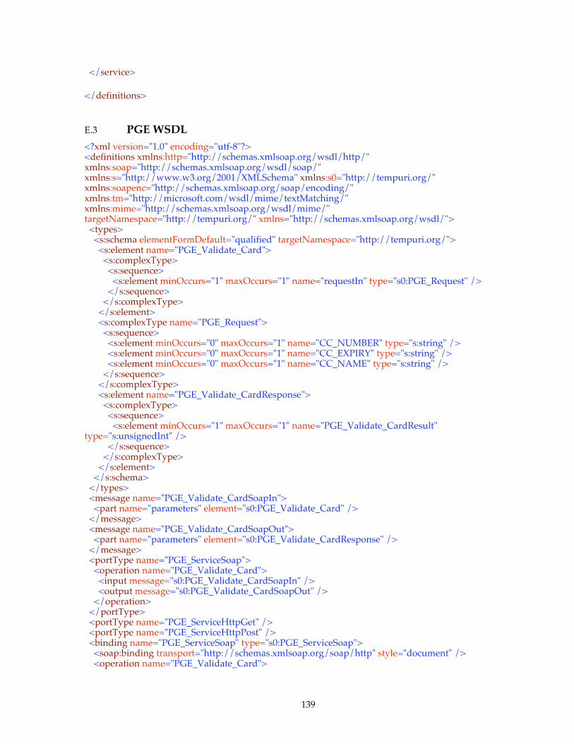
139
</service>
</definitions>
E.3 PGE WSDL <?xml version="1.0" encoding="utf-8"?> <definitions xmlns:http="http://schemas.xmlsoap.org/wsdl/http/" xmlns:soap="http://schemas.xmlsoap.org/wsdl/soap/" xmlns:s="http://www.w3.org/2001/XMLSchema" xmlns:s0="http://tempuri.org/" xmlns:soapenc="http://schemas.xmlsoap.org/soap/encoding/" xmlns:tm="http://microsoft.com/wsdl/mime/textMatching/" xmlns:mime="http://schemas.xmlsoap.org/wsdl/mime/" targetNamespace="http://tempuri.org/" xmlns="http://schemas.xmlsoap.org/wsdl/"> <types> <s:schema elementFormDefault="qualified" targetNamespace="http://tempuri.org/"> <s:element name="PGE_Validate_Card"> <s:complexType> <s:sequence> <s:element minOccurs="1" maxOccurs="1" name="requestIn" type="s0:PGE_Request" /> </s:sequence> </s:complexType> </s:element> <s:complexType name="PGE_Request"> <s:sequence> <s:element minOccurs="0" maxOccurs="1" name="CC_NUMBER" type="s:string" /> <s:element minOccurs="0" maxOccurs="1" name="CC_EXPIRY" type="s:string" /> <s:element minOccurs="0" maxOccurs="1" name="CC_NAME" type="s:string" /> </s:sequence> </s:complexType> <s:element name="PGE_Validate_CardResponse"> <s:complexType> <s:sequence> <s:element minOccurs="1" maxOccurs="1" name="PGE_Validate_CardResult" type="s:unsignedInt" /> </s:sequence> </s:complexType> </s:element> </s:schema> </types> <message name="PGE_Validate_CardSoapIn"> <part name="parameters" element="s0:PGE_Validate_Card" /> </message> <message name="PGE_Validate_CardSoapOut"> <part name="parameters" element="s0:PGE_Validate_CardResponse" /> </message> <portType name="PGE_ServiceSoap"> <operation name="PGE_Validate_Card"> <input message="s0:PGE_Validate_CardSoapIn" /> <output message="s0:PGE_Validate_CardSoapOut" /> </operation> </portType> <portType name="PGE_ServiceHttpGet" /> <portType name="PGE_ServiceHttpPost" /> <binding name="PGE_ServiceSoap" type="s0:PGE_ServiceSoap"> <soap:binding transport="http://schemas.xmlsoap.org/soap/http" style="document" /> <operation name="PGE_Validate_Card">
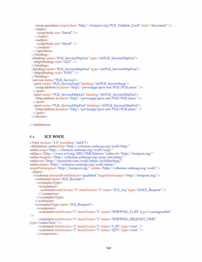
140
<soap:operation soapAction="http://tempuri.org/PGE_Validate_Card" style="document" /> <input> <soap:body use="literal" /> </input> <output> <soap:body use="literal" /> </output> </operation> </binding> <binding name="PGE_ServiceHttpGet" type="s0:PGE_ServiceHttpGet"> <http:binding verb="GET" /> </binding> <binding name="PGE_ServiceHttpPost" type="s0:PGE_ServiceHttpPost"> <http:binding verb="POST" /> </binding> <service name="PGE_Service"> <port name="PGE_ServiceSoap" binding="s0:PGE_ServiceSoap"> <soap:address location="http://povicepge.tpcw.net/PGE/PGE.asmx" /> </port> <port name="PGE_ServiceHttpGet" binding="s0:PGE_ServiceHttpGet"> <http:address location="http://povicepge.tpcw.net/PGE/PGE.asmx" /> </port> <port name="PGE_ServiceHttpPost" binding="s0:PGE_ServiceHttpPost"> <http:address location="http://povicepge.tpcw.net/PGE/PGE.asmx" /> </port> </service>
</definitions>
E.4 ICE WSDL <?xml version="1.0" encoding="utf-8"?> <definitions xmlns:http="http://schemas.xmlsoap.org/wsdl/http/" xmlns:soap="http://schemas.xmlsoap.org/wsdl/soap/" xmlns:s="http://www.w3.org/2001/XMLSchema" xmlns:s0="http://tempuri.org/" xmlns:soapenc="http://schemas.xmlsoap.org/soap/encoding/" xmlns:tm="http://microsoft.com/wsdl/mime/textMatching/" xmlns:mime="http://schemas.xmlsoap.org/wsdl/mime/" targetNamespace="http://tempuri.org/" xmlns="http://schemas.xmlsoap.org/wsdl/"> <types> <s:schema elementFormDefault="qualified" targetNamespace="http://tempuri.org/"> <s:element name="ICE_Reorder"> <s:complexType> <s:sequence> <s:element minOccurs="1" maxOccurs="1" name="ICE_req" type="s0:ICE_Request" /> </s:sequence> </s:complexType> </s:element> <s:complexType name="ICE_Request"> <s:sequence> <s:element minOccurs="1" maxOccurs="1" name="SHIPPING_O_ID" type="s:unsignedInt" /> <s:element minOccurs="1" maxOccurs="1" name="SHIPPING_REQUEST_TIME" type="s:dateTime" /> <s:element minOccurs="1" maxOccurs="1" name="I_ID" type="s:int" /> <s:element minOccurs="1" maxOccurs="1" name="QTY" type="s:int" /> </s:sequence>
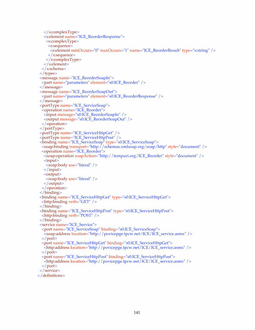
141
</s:complexType> <s:element name="ICE_ReorderResponse"> <s:complexType> <s:sequence> <s:element minOccurs="0" maxOccurs="1" name="ICE_ReorderResult" type="s:string" /> </s:sequence> </s:complexType> </s:element> </s:schema> </types> <message name="ICE_ReorderSoapIn"> <part name="parameters" element="s0:ICE_Reorder" /> </message> <message name="ICE_ReorderSoapOut"> <part name="parameters" element="s0:ICE_ReorderResponse" /> </message> <portType name="ICE_ServiceSoap"> <operation name="ICE_Reorder"> <input message="s0:ICE_ReorderSoapIn" /> <output message="s0:ICE_ReorderSoapOut" /> </operation> </portType> <portType name="ICE_ServiceHttpGet" /> <portType name="ICE_ServiceHttpPost" /> <binding name="ICE_ServiceSoap" type="s0:ICE_ServiceSoap"> <soap:binding transport="http://schemas.xmlsoap.org/soap/http" style="document" /> <operation name="ICE_Reorder"> <soap:operation soapAction="http://tempuri.org/ICE_Reorder" style="document" /> <input> <soap:body use="literal" /> </input> <output> <soap:body use="literal" /> </output> </operation> </binding> <binding name="ICE_ServiceHttpGet" type="s0:ICE_ServiceHttpGet"> <http:binding verb="GET" /> </binding> <binding name="ICE_ServiceHttpPost" type="s0:ICE_ServiceHttpPost"> <http:binding verb="POST" /> </binding> <service name="ICE_Service"> <port name="ICE_ServiceSoap" binding="s0:ICE_ServiceSoap"> <soap:address location="http://povicepge.tpcw.net/ICE/ICE_service.asmx" /> </port> <port name="ICE_ServiceHttpGet" binding="s0:ICE_ServiceHttpGet"> <http:address location="http://povicepge.tpcw.net/ICE/ICE_service.asmx" /> </port> <port name="ICE_ServiceHttpPost" binding="s0:ICE_ServiceHttpPost"> <http:address location="http://povicepge.tpcw.net/ICE/ICE_service.asmx" /> </port> </service> </definitions>
142
Appendix F - EXECUTIVE SUMMARY
This appendix includes a sample Executive Summary, which includes the following 3 pages:
Overview Page
Pricing Page
Numerical Quantities Summary Page.
Clause 7 - and Clause 8.2 give a detailed description of the REQUIRED format and content of the Executive Summary. This sample is provided only as an illustration of the REQUIREMENTS set forth in this specification. In the event of a conflict between this example and the specification, the specification shall prevail.
The REQUIRED format of the TPC-App Executive Summary MAY change from time to time. The latest version of the REQUIRED format is available upon request from the TPW administrator (see cover page).

143
F.1 Implementation Overview Page
The following pages demonstrate how the format of the Executive Summary pages MUST appear for a TPC-App result:

144
F.2 Pricing Page
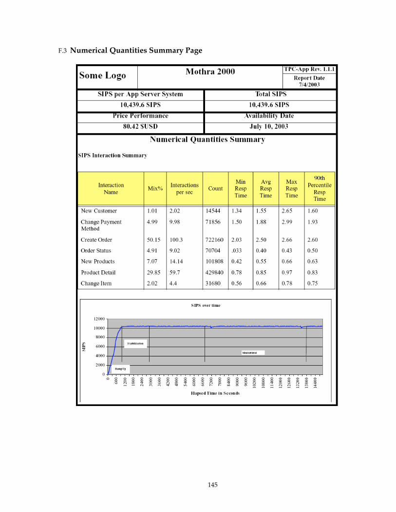
145
F.3 Numerical Quantities Summary Page
146
Appendix G - Throughput scaling limits
This appendix shows the derivation of the throughput limits used in clause Error! Reference source not found.. The purposes of the limits are :
1. To prevent reporting a Total SIPS that exceeds an upper bound on total throughput.
2. To prevent over-scaling of the SUT.
G.1 An upper bound on Total SIPS An upper bound on Total SIPS is calculated as the number of Acitve Ebs times an upper upper bound on SIPS-per-Active-EB. The upper bound on SIPS-per-Active-EB = 1 / (Lower bound on average SIRT) The lower bound on average SIRT is calculated by assuming an average SIRT of 0 seconds for the Web Service Interaction types Order Status, New Products, Product Detail, and Change Item. The average SIRT for the Web Service Interaction types New Customer, Change Payment, and Create Order is taken to be 0.5 x 1 second, because 50% of these Web Service Interactions must include a 2 second delay. Using mix-weighted averages of these SIRTs gives: Lower bound on average SIRT = (0.01 + 0.05 + 0.50) * 1.0 sec. + (0.05 + 0.07 + 0.30 + 0.02) * 0.0 sec
= 0.56 sec. Upper bound on Total SIPS = (1 / 0.56) * Active EBs
= 1.78 * Active EBs
G.2 Preventing the over-scaling of the SUT
To prevent over-scaling the SUT, the reported Total SIPS MUST NOT fall short of the following lower bound on Total SIPS, defined as 50% of the upper bound on Total SIPS : Lower bound on Total SIPS = 0.5 * 1.78 * Active Ebs
= 0.89 * Active EBs

147
Appendix H -
TPC-App Rationale
Why the 3 hour steady state requirement?
The subcommittee believes that the 3 hour steady state requirement is sufficient to prove stability and repeatability for the given workload and allows for ease of benchmarking without requiring extensive proofs of steady state (e.g., requiring 8 hour Test Runs, repeatability runs, etc).
Why are orders that are created by a new customer never accessed outside of the session that created the new customer?
For the RBE to choose new customers during the Test Run, the RBE would have to have knowledge of what customers had been created during this and all previous test runs. This would have made the RBE overly complex.
Why are items not added or removed from the ITEM table?
Items have their publish date (I_PUB_DATE) modified by the Change Item Interaction. This simulates the addition and deletion of items from the database. To add and delete items from the database would require the RBE to have knowledge of exactly what is in the database at any given time. This would have made the RBE too complex to develop and maintain.
Why is the value of S_QTY handled the way that it is?
The RBE needs to know a value that will generate a back order condition. The value of S_QTY_is updated in Stock Management to simulate the receipt of new stock. The value moves between 20 and 30. The RBE generates a quantity of 1 to 10 for non back orders and a value of 40 for back orders. Without this fixed method of managing stock levels, the application would quickly become unbalanced with regards to actual stock quantities. This level of complexity in the benchmark was deemed undesirable.
Why is the WSDL for the application not mandated?
Each Web service IDE creates WSDL for the Web services being developed. While the WSDL generated by the individual IDEs is very similar it is not identical. Additionally the WSDL document may be generated by hand without the involvement of any IDE. The decision was made not to mandate WSDL because any mandated WSDL may unfairly favor one vendor over another.
148
Why is there a requirement that access from the Application Program to any component used in the benchmark be performed with APIs available to the Managed Environment?
One of the primary goals of TPC-App is to showcase the capabilities of Application Servers that host managed enviroments. The requirement for the 'seamless' integration of products that perform functions for this benchmark encourages vendors whose products do not currenty have a managed environment interface to provide one. Also, the subcommittee felt that allowing 'glue code' which does not run in a managed environment would potentially allow implementations to perform processing explicitly intended to be performed by the Managed Environment to be 'offloaded' to non-mamanged code.
Why does the database not have referential integrity requirements?
Because this benchmark is application server oriented, the subcommittee felt that a referential integrity requirement was not appropriate. Note, no other TPC benchmark has this requirement.
Why are there benchmark requirements for RAID storage? RAID storage is representative and expected as a minimal requirement in a 24x7 business-to-business environment. Typically redundancy requirements extend beyond storage.
Why is the ICE removed from the atomic operations for the Stock Management process?
The best way to perform this B2B Web service transaction is with the use of Transactional Web services. However since the specification for transactional Web services is still a work in progress the subcommittee made the best compromise possible.
Why is there no requirement for a traditional Web server product?
The industry is moving in a direction that allows products other than traditional Web servers to host managed environments that perform Web services. An example of this would be a Database Server. Most Database Server vendors either support this model or plan to support it in the near future.
Why is O_DISCOUNT set to ‘0’ for the initial database population?
O_DISCOUNT is set to zero so that the ORDER and CUSTOMER tables can be loaded independently.
Why is it required to resubmit requests when an error occurs, and why is there a maximum of 20 retries on any single Web Service Request?
This was done to protect against a poorly written application that does not handle error conditions correctly, but allows for a reasonable amount of communication errors, server busy errors, etc…
Why is there is an 8 hour storage requirement even though the SUT represents a 24x7 operation?

149
The throughput represented is intended to be a peak workload. Feedback from existing sites indicates peak throughput to be about 3 times the average throughput. The requirement for 8 hour storage at peak throughput is representative of the storage requirements for 24 hours at average throughput.
Why is the database not the focus of this benchmark as in other TPC benchmarks?
This is by design. The intent is to stress the application server and other middle tier components without the database being a bottleneck as quickly.
Why do the timestamps taken for the SIRT (T1 and T2) include processing that occurs on the RBE (i.e., T2 = next Web Service Interaction’s T1)?
The subcommittee looked at other methods for measuring T1 and T2 with the idea in mind that there is a short interval in the RBE to set up the next Web Service Interaction. Attempts to remove this time-slice introduced additional complexity in the benchmark. The subcommittee decided to make T1 and T2 the same for ease of benchmarking and auditing purposes.
Why are there <Start Database Transaction> and <End Database Transaction> tags around single selects from the database?
This was done to ensure that all database products were reading the database with the same isolation level.
While the benchmark requires SSL/TLS with certificates from server to client, it does not require client certificate authentication. Is this normal for a B2B environment?
Review of typical customer environments indicated that client certificates were rarely used.
Are the key sizes and restrictions for SSL representative and appropriate for this business model?
The key sizes used are appropriate for the products used in this benchmark. These requirements are slightly increased over default settings for most products.
What options are available to verify that the SSL/TLS handshake requirements per Business Session are met?
There are software tools available such as Ethereal (www.ethereal.com) which can act as a software based network protocol analyzer. Additionally, various OS platforms MAY have the ability to log additional session details.