Embed Size (px)
Citation preview

Issue DateINSTALLATION
INSTRUCTIONS
Publication No.
Honda Dealer: Please give a copy of these instructions to your customer.
© 2015 American Honda Motor Co., Inc - All Rights Reserved. 0SR71-HL4-A00 1 of 5
ApplicationAccessory
PARTS LIST
TWO-PIECE POLY WINDSCREEN (HARD COAT)
P/N 0SR71-HL4-A00SXS1000M/M3P/M5D/M5P
MII 15262
September 2015
TOOLS AND SUPPLIES REQUIRED4 mm hex wrenchTorque wrenchPower drill5/16 inch (8 mm) drill bit
TORQUE CHARTSTighten all screws, bolts, and nuts to their specified torque values. Refer to the Service Manual for the torque values of the removed parts.
Item N·m kgf·m lbf·ft
6 mm screw and nut 5 0.5 4
USE AND CARE INFORMATION• Check the accessory mount frequently and retighten
if necessary.• Replace this accessory with a new one if it is
damaged or discolored excessively.• When this accessory becomes dir ty, rinse it
thoroughly with cool water to remove loose dirt, then wipe with a clean cloth or sponge.
• Do not use a brush to clean this accessory as it may scratch the surface.
• Never use petroleum solvents such as gasoline, thinner, benzine, acid, or alkaline cleaners.
No. Description Qty
(1) Upper windscreen 1
(2) Lower windscreen 1
(3) Cam lock 5
(4) Hinge bracket 3
(5) Support bracket 1
(6) 6 x 16 mm screw 9
(7) 6 x 20 mm screw 1
(8) 6 x 25 mm screw 2
(9) 6 x 30 mm screw 3
(10) Left hinge arm 1
(11) Right hinge arm 1
(12) Left gasket 1
(13) Right gasket 1
(14) Clamp 2
(15) Nylock nut 2
(16) 6 mm flat washer 1
(17) Fender washer 2
(18) Flange collar 5
(19) 25 mm spacer 2
(20) 6 x 85 mm stud 2
(21) Trim clip 2
(22) Push dart 4
(23) Push nut 4
(24) Cam lever set 2
(25) Small spacer 1
(26) Large spacer 2
(27) Installation Instruction URL (not shown) 1
(1)
(2)
(10) (11) (12) (13)
(16) (17) (18)
(19)
(26)
(5)
(14)
(25)
(21)(20) (9) (8) (23)(6)(7) (22)
(3)
(4)
(24)
(15)
© 2015 American Honda Motor Co., Inc - All Rights Reserved.2 of 5 0SR71-HL4-A00
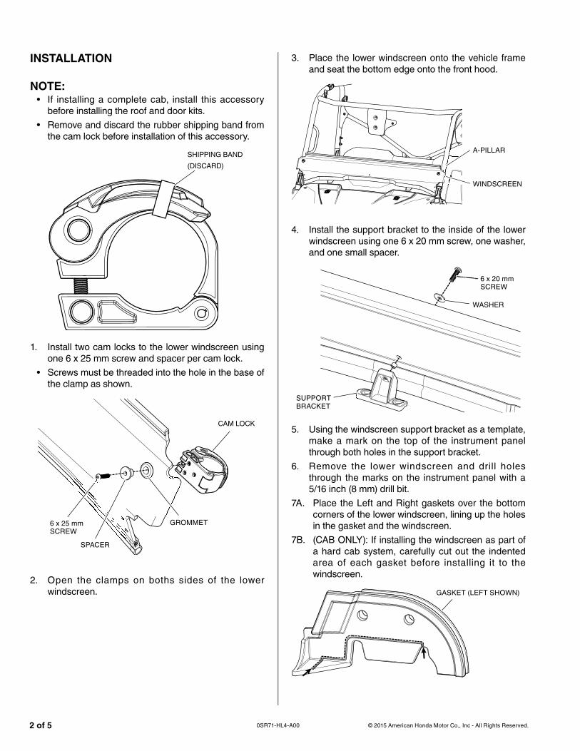
INSTALLATION
NOTE:• If installing a complete cab, install this accessory
before installing the roof and door kits.
• Remove and discard the rubber shipping band from the cam lock before installation of this accessory.
SHIPPING BAND
(DISCARD)(
1. Install two cam locks to the lower windscreen using one 6 x 25 mm screw and spacer per cam lock.
• Screws must be threaded into the hole in the base of the clamp as shown.
CAM LOCK
6 x 25 mm SCREW
SPACER
GROMMET
2. Open the clamps on boths sides of the lower windscreen.
3. Place the lower windscreen onto the vehicle frame and seat the bottom edge onto the front hood.
A-PILLAR
WINDSCREEN
4. Install the support bracket to the inside of the lower windscreen using one 6 x 20 mm screw, one washer, and one small spacer.
SUPPORT BRACKET
WASHER
6 x 20 mm SCREW
5. Using the windscreen support bracket as a template, make a mark on the top of the instrument panel through both holes in the support bracket.
6. Remove the lower windscreen and drill holes through the marks on the instrument panel with a 5/16 inch (8 mm) drill bit.
7A. Place the Left and Right gaskets over the bottom corners of the lower windscreen, lining up the holes in the gasket and the windscreen.
7B. (CAB ONLY): If installing the windscreen as part of a hard cab system, carefully cut out the indented area of each gasket before installing it to the windscreen.
GASKET (LEFT SHOWN)

© 2015 American Honda Motor Co., Inc - All Rights Reserved. 3 of 50SR71-HL4-A00
8. Install the gaskets to the windscreen using two push darts and push nuts per side, as shown.
PUSH NUT
PUSH DART
GASKET (LEFT SHOWN)
9. Reinstall the lower windscreen.
Secure the lower windscreen to the instrument panel by placing trim clips through the windscreen bracket and into the holes.
TRIM CLIP
10. Align the cam locks around the cab A-pillars and snap the arms closed. Do this on both sides.
11. Adjust clamp tension by rotating the threaded arm clockwise to tighten, counter-clockwise to loosen.
THREADED ARM
INSTALLATION - UPPER WINDSCREEN12. Insert two 6 x 16 mm screws into the holes in the
hinge bracket and then install them into the base of the cam lock as shown.
13. Insert one 6 x 16 mm screw through the hole in the cam lock and then intall it into the hinge bracket as shown.
6 x 16 mm SCREW
CAM LOCK
6 x 16 mm SCREW
HINGE BRACKET
14. Repeat Steps 12 and 13 for the remaining two hinges and clamps.
15. Install a hinge/cam lock assembly into each grommet using one 6 x 30 mm screw and flange collar, noting the orientation of the hinge/clamp assembly as shown.
6 x 30 mm SCREWGROMMET
FLANGE COLLARHINGE/CAM LOCK
© 2015 American Honda Motor Co., Inc - All Rights Reserved.4 of 5 0SR71-HL4-A00
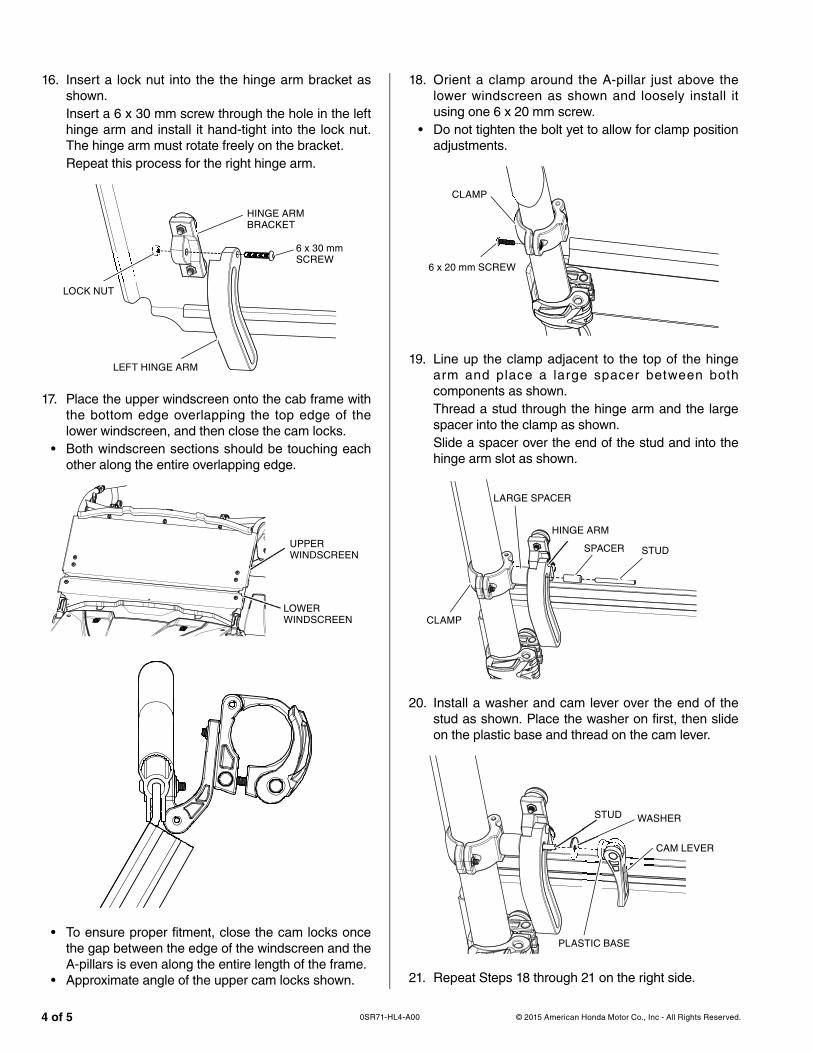
16. Insert a lock nut into the the hinge arm bracket as shown.Insert a 6 x 30 mm screw through the hole in the left hinge arm and install it hand-tight into the lock nut. The hinge arm must rotate freely on the bracket.Repeat this process for the right hinge arm.
HINGE ARM BRACKET
6 x 30 mm SCREW
LEFT HINGE ARM
LOCK NUT
17. Place the upper windscreen onto the cab frame with the bottom edge overlapping the top edge of the lower windscreen, and then close the cam locks.
• Both windscreen sections should be touching each other along the entire overlapping edge.
UPPER WINDSCREEN
LOWER WINDSCREEN
• To ensure proper fitment, close the cam locks once the gap between the edge of the windscreen and the A-pillars is even along the entire length of the frame.
• Approximate angle of the upper cam locks shown.
18. Orient a clamp around the A-pillar just above the lower windscreen as shown and loosely install it using one 6 x 20 mm screw.
• Do not tighten the bolt yet to allow for clamp position adjustments.
6 x 20 mm SCREW
CLAMP
19. Line up the clamp adjacent to the top of the hinge arm and place a large spacer between both components as shown.Thread a stud through the hinge arm and the large spacer into the clamp as shown.Slide a spacer over the end of the stud and into the hinge arm slot as shown.
STUDSPACER
LARGE SPACER
HINGE ARM
20. Install a washer and cam lever over the end of the stud as shown. Place the washer on first, then slide on the plastic base and thread on the cam lever.
WASHERSTUD
CAM LEVER
S U
21. Repeat Steps 18 through 21 on the right side.
CLAMP
PLASTIC BASE

© 2015 American Honda Motor Co., Inc - All Rights Reserved. 5 of 50SR71-HL4-A00
• The overlapping edge between both the upper and lower sections of the windscreen should fit together as shown.
22. To open the “folding” windscreen, loosen the cam lever handles and push the upper windscreen forward. When the windscreen reaches the desired opening angle, tighten both cam lever handles.


