Embed Size (px)
Citation preview
APPLICATION OF WATER MIST PRE-COOLING ON THE AIR-COOLED CHILLERS
Jia Yang1,2, K.T. Chan1, and Xiangsheng Wu2
1Department of Building Services Engineering, The Hong Kong Polytechnic University, Hong Kong, China 2Department of Real Estate and Environmental Engineering,
Logistical Engineering University, Chongqing, China
ABSTRACT The operation of air-cooled chillers accounts for significant energy consumption in local commercial buildings, and low operational efficiency especially under partial load conditions and poor control are part of reasons for such huge energy consumption. Chiller efficiency can be improved by enhancing heat transfer rate in condensers. This paper considers how the chiller performance can be improved by using water mist to pre-cool ambient air entering the condensers to decrease compressor power. A simulation analysis on an air-cooled chiller equipped with a water mist pre-cooling system under head pressure control shows that applying water mist pre-cooling enables the coefficient of performance (COP) to increase. Variable condensing temperature control is superior to head pressure control, where condenser effectiveness is enhanced by staging all condenser fans to decrease the condensing temperature. When the chiller with a water mist pre-cooling system operates under condensing temperature control, the analysis indicates that the COP improvements would be more considerable. The cooling energy saving potential for a representative office building in Hong Kong will be assessed when water mist pre-cooling and variable condenser temperature control are applied to the air-cooled chiller plant.
INTRODUCTION Air-cooled chillers are widely used to provide cooling energy in the form of chilled water in air-conditioned buildings in the subtropical regions. The operation of chillers usually takes up the highest proportion of the total electricity consumption of buildings (Yik and Burnett, 2001; Yu and Chan, 2005a; Yu and Chan, 2005b). The operating efficiency of air-cooled chillers is low compared to water-cooled chillers. However, air-cooled chiller systems gain popularity due to its flexibility, especially for the cities that have water shortage problem. Low operational efficiency especially under partial load conditions and poor control are part of reasons for such huge energy consumption. To improve energy efficiency, chiller systems should be properly operated to meet the cooling load under external and internal conditions with least energy consumption.
The operating efficiency of air-cooled chillers is low compared with water-cooled chillers. The deficient performance of air-cooled chillers is mainly due to head pressure control (HPC) under which the condensing temperature floats around a high set point of 50˚C based on a design outdoor temperature of 35˚C, irrespective of different chiller loads and weather conditions. Some researchers have stated the opportunity to lower the condensing temperature to save compressor power to improve the operating efficiency of air-cooled chillers. Variable condensing temperature control (CTC) is proposed as an alternative to HPC to lower the condensing temperature in response to changes of the ambient and load conditions (Yu and Chan, 2005b; Yu and Chan, 2006a). As air-cooled chillers apply condenser fans to force outdoor air to condense and slightly subcool the refrigerant. Under such conditions, the extent of the condensing temperature decrease is constrained by the dry-bulb temperature of outdoor air. As evaporative cooling could decrease the temperature of the outdoor air, it is possible to use evaporative pre-coolers to cool outdoor air before entering air-cooled condensers. Evaporative pre-coolers could be installed in front of air-cooled condensers, which can pre-cool outdoor air before entering the condensers while consuming less than 15% of the cooling water required by cooling towers and evaporative condensers (Yu and Chan, 2006b). With these coolers, air-cooled chillers can operate more efficiently because the condensing temperature drops followed by any reduced outdoor temperature. However, the condensing fans have to increase their suction power to maintain the heat rejection rate while the pressure of the air entering the condenser is reduced after passing through the evaporative pre-cooler. The pressure drop across the pre-coolers incurs additional fan power, but the compressor power dropped following the decrease in condensing temperature. The use of the pre-cooler resulted in the beneficial tradeoff (Zhang et al. 2000). Zhang (2000) have indicated that the use of evaporative pre-coolers can bring about a 14.7% increase in the COP of air-cooled chillers working in a hot and dry environment. According to a simulation study (Yu and Chan, 2005c), a 1.4–14.4% decrease in chiller power and a 1.3–4.6% increase in the
Eleventh International IBPSA Conference Glasgow, Scotland
July 27-30, 2009
- 2204 -

refrigeration effect achieved when an air-cooled reciprocating chiller with an evaporative pre-cooler operated under HPC. When CTC replaced HPC, the chiller power could further reduce by 1.3–4.3% in certain operating conditions. An alternative for evaporative cooling is to install water mist system to pre-cool the air entering condensers. The water mist precooling system is not a new concept, and they have been applied successfully in the industries (Hsieh and Yao, 2006; Jones and Robertson, 1998; Turnbull,2006). However, the application of water-mist system associated with a chiller system is not common. This paper aims to investigate how the energy performance of air-cooled chillers can be improved by water mist pre-cooling. When CTC replaces HPC, the energy performance of the air-cooled chiller will be improved, and it is worth investigating how the use of water mist pre-cooling can complement CTC to further enhance the performance of air-cooled chillers.
WATER MIST SYSTEM The typical water mist system comprises of a high pressure pump motor unit, filter unit, atomization nozzles, high pressure tubing, low pressure tubing, etc. The high pressure pump can operate to deliver water through the tubing at a high pressure of around 70 bars, and the water is pumped through highly specialized low flow atomization nozzles to form a water mist of very fine droplets in 10-micron size. When the ultra fine water droplets are sprayed into the atmosphere, they quickly absorb the heat in the environment and evaporate, and then the air is cooled by evaporative cooling. At a given temperature and humidity, the sprayed water mist will increase the absolute humidity and decrease the air temperature, but they are limited by the wet-bulb temperature. When the water mist system is coupled with the air-cooled chillers, the temperature of the air at the inlet of the air-cooled condenser will decrease compared the temperature of the ambient air, as well the condensing temperature and condensing pressure will decrease accordingly, as shown in Figure 1.
1’
Tcd
Tev
3’
4
T’cd
3
P’cd
2
2’ 3’
4’
Pcd
Pev
Pres
sure
(kPa
)
Refrigerant specific enthalpy, hi (kJ/kg)
1
Figure 1 Vapour compression cycle of the
refrigeration circuit
The refrigeration cycle of the chiller system with water mist system is changed from the cycle 1-2-3-4-1 to 1’-2’-3’-4’-1’. With the decrease of the condensing pressure, the work of the compressor will decrease. However, the cooling capacity increases, so the COP of the chiller system will increase. Theoretically, air-cooled condenser coupled with a water mist system will improve the chiller efficiency, but it will depend on the ambient climatic conditions, cooling load, etc.
CHILLER MODEL System and model descriptions In this research project, the air-cooled chiller plant installed in an institutional complex was used for studying, which comprises of five identical chillers connected in parallel. Each chiller used the refrigerant R134a and had a nominal cooling capacity of 1105 kW, rated under the operating conditions of entering condenser air temperature (Tcdae) at 35˚C, entering/leaving chilled water temperatures at 12˚C/7˚C and chilled water flow rate at 50 l/s. The rated electric power demand of each chiller is 398kW. The rated COP is, therefore, about 2.8. The chiller has two identical refrigeration circuits. The air-cooled condenser contains 16 identical condenser fans to deliver a total airflow rate of 85.5 m3/s by eight groups, and each refrigeration circuit operates with four fan groups. Under this arrangement, heat rejection airflow is regulated from 10.7 through 85.5 m3/s in eight steps, depending on the ambient and load conditions. Each fan power is 4.1 kW and the total fan power is 65.6 kW when all the fans are operating. One of the air-cooled chiller of the chiller plant was equipped with a water mist system with two identical water mist circuits, each with a high pressure pump at rating of 0.75kW and dedicated to one refrigeration circuit. The model of the water mist is AJ2, and the flow rate is 2 l/min with the operating pressure 70 bar for each water mist circuit.
Modelling of twin circuit chillers in operation The measured operating data for the air-cooled chiller included the power of each compressor(Ecc), the power of each refrigeration circuit (Ech), chilled water supply temperature (Tchws), chilled water return temperature (Tchwr), evaporating temperature (Tev) and condensing temperature (Tcd) of each refrigeration circuit. Those data recorded by the building management system (BMS) . The chiller model was developed using the simulation program TRNSYS (2000). The chiller model is based on the field chiller mentioned befoe. As this chiller has two identical refrigeration circuits, namely circuit Ⅰand circuit Ⅱ, there may be three operating modes for this chiller, circuit Ⅰoperating, circuit Ⅱ operating, and both circuits operating. As circuit Ⅰand circuit Ⅱoperating are the same, the
- 2205 -

Tchws Tchwr
Tchws1
Tchwr1
chiller model will only consider the circuit Ⅰoperating and both circuits operating modes. The schematic of the air-cooled chiller with two refrigeration circuits is shown in Figure 2. The cooling load of the chiller can be allocated with the refrigeration circuits randomly, and the chiller load (Qcl) is as follow:
( )cl w w chwr chwsQ m c T T= ⋅ ⋅ − (1)
The cooling capacity circuit Ⅱ(Qcl2 ):
2 1 1( )cl w w chwr chwsQ m c T T= ⋅ ⋅ − (2)
Where wm is the chilled water mass flow rate,
wc is
the specific heat capacity of water, 1chwsT and
1chwrT are the chilled water supply and return temperature for refrigeration circuit Ⅱ, repectively. The cooling capacity of circuit Ⅰis the sum of cooling capacity of the two sections,
1 11 12cl cl clQ Q Q= + (3)
11 1( )cl w w chwr chwrQ m c T T= ⋅ ⋅ − (4)
12 1( )cl w w chws chwsQ m c T T= ⋅ ⋅ − (5)
1 2cl cl clQ Q Q= + (6)
Heat rejection (Qcd) was calculated by Eq. (7). The heat rejection airflow (Va) was determined by Eq. (8), where Tcdal is the temperature of air leaving the condenser. The total condenser fan power was determined by Eq.(9), assuming that the airflow is directly proportional to the power of a fan running at constant speed.
cd cl ccQ Q E= + (7)
a cd a pa cdal cdae /( ( - ))V Q C T Tρ= (8)
cf cf , ,. /rated a a ratedE E V V= (9)
The chiller COP is expressed as cooling capacity (Qcl) over chiller power (Ech), which can be defined for each refrigeration circuit in the form as follow
/cl chCOP Q E= (10)
Figure 2 Schematic of the air-cooled chiller
Figure 3 gives the procedure for the air-cooled chiller to determine the condensing temperature (Tcd) and heat rejection airflow (Va) . For any given cooling capacity (Qcl), compressor power (Ecc) and heat rejection (Qcd) will vary according to the condensing temperature set point (Tcdsp).
Tcd,max < Tcdal ?
INPUTS Qcl, Ecc,o, Tcd,o (ITER=0)
Tcd < Tcdo ?
|Tcdo - Tcd| < 0.005?
N
Y
Ncf = Ncf+1
Qcd
Tcdal
AUcd = f(Va, mr)
Tcd
Y
N
NTcdo = Tcd ITER=ITER+1
Y
Ech, chiller COP
INPUTS Tcdae Tcdsp
,cf
a,tot a pa cdsp cdae
Interger . ( )cf tot cdN QN
V C T Tρ
⎛ ⎞= ⎜ ⎟⎜ ⎟−⎝ ⎠
Ecc = f(Tcd, PLR)
cf N i=
,
1( ) cf tot
i iMax i N= +
=
a,tota
cf,tot
V
N cfV N=
cfN i<= (i=1)
Y
Figure 3 Procedures for determining the chiller operating variables
Validation of the chiller model The validity of the chiller model was checked by comparing the modelled results with the operating data of the chiller. The measured data used for validating the chiller model came from the field chiller operating under head-pressure control. For head-pressure control, the set-point condensing temperature (Tcdsp) was fixed at 45 °C, irrespective of how the chiller load and outdoor temperature varied. Figure 4 shows that the modelled results of the chiller’s COP agreed well with the corresponding measured data. Indeed, for most of data points, the uncertainty of the chiller’s COP was less than 10%, and, for more than 70% of these, the uncertainty was within ±5%. With this good agreement, it is justifiable to use the chiller model to investigate the chiller efficiency improvement with water mist system under various operating conditions.
10%
-10%
1.00
1.50
2.00
2.50
3.00
3.50
1.00 1.50 2.00 2.50 3.00 3.50
Measured COP
Mod
elle
d C
OP
Figure 4 Comparison between the modelled and
measured chiller COP
Water mist model By using this chiller model, the performance of the air-cooled chiller before installing the water mist system can be investigated. Based on this chiller model, the change of the performance of the chiller after installing water mist system will be assessed. When the water mist system is coupled with the air-cooled condensers, the air temperature entering the condenser will decrease from the outdoor air temperature. While the water mist system operates, Tcdae refers to the temperature (Tcdae’) reduced from outdoor dry-bulb temperature (Tdb), of which the increased moisture content Wdb’ is dependent on air velocity (Va) and the mist generation rate (mmist).
- 2206 -

Their relationship is given by Eqs. (11) to (13). In cases where the calculated Wdb’ is greater than the maximum allowable moisture content at the saturation state, Tcdae’ becomes wet-bulb temperature (Twb) and the surplus water droplet may fall down to the ground or be carried to the condenser coil. ΔW = mmist/(Va ρa) (11) Wdb’ = Wdb + ΔW (12) Tcdae’ = (hdb - 2501 Wdb’)/(1.006+1.805 Wdb’) (13) As the decread temperature Tcdae’ is affected by the air velocity, these equations will be added into the chiller model established before solved through an iterative process shown in Figure 5. In this part, the COP calculation is based on the overall power input to the compressors, condenser fans and high pressure pumps when operating. For any given inputs, Tdb was taken to be the initial value of Tcdae.
Tcd,max < Tcdal ?
INPUTS Qcl, Ecc,o, Tcd,o (ITER=0)
Tcd < Tcdo ?
|Tcdo - Tcd| < 0.005?
N
Y
Ncf = Ncf+1
Qcd
Tcdal
AUcd = f(Va, mr)
Tcd
Y
N
NTcdo = Tcd ITER=ITER+1
Y
Ech, chiller COP
INPUTS Tcdae Tcdsp
,cf
a,tot a pa cdsp cdae
Interger . ( )cf tot cdN QN
V C T Tρ
⎛ ⎞= ⎜ ⎟⎜ ⎟−⎝ ⎠
Ecc = f(Tcd, PLR)
cf N i=
,
1( ) cf tot
i iMax i N= +
=
a,tota
cf,tot
V
N cfV N=
cfN i<= (i=1)
Y
', dbW WΔ
'cdaeT Figure 5 Procedure for evaluating operating variables of the chiller with water mist pre-cooling The water mist systems were designed to provide a total mist generation rate of 0.067 l/s, and the sytem produces a cloud of very fine water droplets in 10-micron size via nozzles, the ultra fine water droplets quickly absorb the heat in the environment and could be fully vaporized by the ambient air before entering the condenser, so the model didn’t take into account the various droplet diameter.
COOLING LOADS OF THE OFFICE BUILDING For generality, the cooling energy saving potential for a representative office building in Hong Kong will be investigated when water mist pre-cooling is applied to the air-cooled chiller plant. In the calculation of hourly building cooling loads for the representative office building, detailed features of these buildings in Hong Kong were compiled into the building energy simulation program EnergyPlus. The features include the envelop orientation, construction, ventilation and air-conditioning requirements, occupancy, equipment power density, and operating schedules. The hourly local weather data in 2007 were used.
According to a survey of 64 commercial buildings in Hong Kong (Chan, 1996), the construction characteristics of high-rise office buildings in Hong Kong were identified and a reference building was developed as the basis for simulation. The reference building is 40-storey high with building parameters representing the average of those that could be expected among the new buildings and the existing ones in Hong Kong, which is a squared office building (36 m by 36 m) with curtain-wall construction and a centralized HVAC system, and has a 3.2 m floor-to-floor height and a window height of 1.6 m. This represents a window-to-wall ratio (WWR) of 50%. For the representative office building, there were 2968 cooling hours, and the cooling hours accounted for 95% of the total 3120 office hours. The chillers and pumps needed to operate at a building load ratio of below 0.5 for 66.7% of the total cooling hours. The peak load range of 0.9 to 1 accounted for only 1.08% of the total cooling hours. To meet the peak cooling load of 7338kW, the office building’s chiller plant was designed with seven air-cooled screw chillers, each of which had a nominal cooling capacity of 1105 kW as studied before. Conventional chiller sequencing was considered in the simulation so all the chillers were operating at the same load, and no additional chillers started to operate until each of the running chillers was operating at full load. Given seven steps of staging chillers to meet the changing building cooling load, the opportunity to operate the chillers at higher loads increased considerably. Table 1 shows the frequency distribution of hourly data of chiller part load ratrio. The chillers were able to work at a part load ratio of 0.7–1 with outdoor temperatures ranging between 15–35 oC for over 80.8% of the operating time.
Table 1 Frequency distribution of the hourly data of chiller
loads Chiller part load ratio Outdoor
temperature(oC)
0–0.1
0.1–0.2
0.2–0.3
0.3–0.4
0.4–0.5
0.5–0.6
0.6–0.7
0.7–0.8
0.8–0.9
0.9–1 Subtotal
15–17 0 0 5 43 66 41 24 19 15 4 217 17–19 0 0 0 0 0 70 55 56 61 53 295 19–21 0 0 0 0 0 65 68 74 79 56 342 21–23 0 0 0 0 0 8 62 85 106 83 344 23–25 0 0 0 0 0 2 43 89 83 90 307 25–27 0 0 0 0 0 0 9 87 161 125 382 27–29 0 0 0 0 0 0 5 30 209 168 412 29–31 0 0 0 0 0 0 2 28 223 233 486 31–33 0 0 0 0 0 0 0 4 69 102 175 33–35 0 0 0 0 0 0 0 0 4 4 8 Subtotal 0 0 5 43 66 186 268 472 1010 918 2968
RESULTS As this chiller has two identical refrigeration circuits, and there may be three operating modes for this chiller, circuit Ⅰoperating, circuit Ⅱ operating, and both circuits operating. The cooling load of the chiller can be allocated with the refrigeration circuits
- 2207 -

randomly. With the different operating mode, the cooling effect of the operating chiller with water mist system will be different. In this paper, two control strageties will be considered for each operating chiller when the traditional chiller sequence is applied, one is that the cooling load is equally shared between the two refrigeration circuits (Scheme A), the other one is that only one refrigeration circuit operate until the operating circuit is operating at full load, then the other refrigeration circuit start to operate and provide the additional cooling load needed (Scheme B). In order to highlight the cooling effect of water mist system, the base cases for the Scheme A and B are the operating conditions without water mist pre-cooling under head pressure control, respectively. When operating, the COP calculation is based on the overall power input to the compressors, condenser fans and high pressure pumps of water mist system. A straightforward strategy to operate the water mist system is applid, which is that the mist system operate continuously with the on-line chiller.
Improvement in chiller efficiency under Scheme A Figures 6 to 8 show the results of the percentage change of COP from the base case under Scheme A with respect to different weather parameters.
0%
5%
10%
15%
20%
0 20 40 60 80 100
Relative humidity / %
CO
P im
prov
emen
t
(a) Relative humidity
0%
5%
10%
15%
20%
0 2 4 6 8 10 12 14 16
Dry-bulb temperature / oC
CO
P im
prov
emen
t
(b) Dry bulb temperature
0%
5%
10%
15%
20%
0 2 4 6 8 10
Temperature difference / oC
CO
P im
prov
emen
t
(c) Temperature difference between dry-bulb and
wet-bulb temperature Figure 6 COP improvement at PLR of 0.2-0.3
-5%
0%
5%
10%
15%
20%
25%
30%
0 20 40 60 80 100
Relative humidity / %
CO
P im
prov
emen
t
(a) Relative humidity
-5%
0%
5%
10%
15%
20%
25%
30%
0 5 10 15 20 25 30
Dry-bulb temperature / oC
CO
P im
prov
emen
t
(b) Dry bulb temperature
-5%
0%
5%
10%
15%
20%
25%
30%
0 2 4 6 8 10
Temperature difference / oC
CO
P im
prov
emen
t
(c) Temperature difference between dry-bulb and
wet-bulb temperature
Figure 7 COP improvement at PLR of 0.5-0.6
-5%
0%
5%
10%
15%
20%
25%
30%
35%
0 20 40 60 80 100
Relative humidity / %
CO
P im
prov
emen
t
(a) Relative humidity
-5%
0%
5%
10%15%
20%
25%
30%
35%
0 5 10 15 20 25 30 35 40
Dry-bulb temperature / oC
CO
P im
prov
emen
t
(b) Dry bulb temperature
- 2208 -
-5%
0%
5%
10%15%
20%
25%
30%
35%
0 2 4 6 8 10
Temperature difference / oC
CO
P im
prov
emen
t
(c) Temperature difference between dry-bulb and
wet-bulb temperature
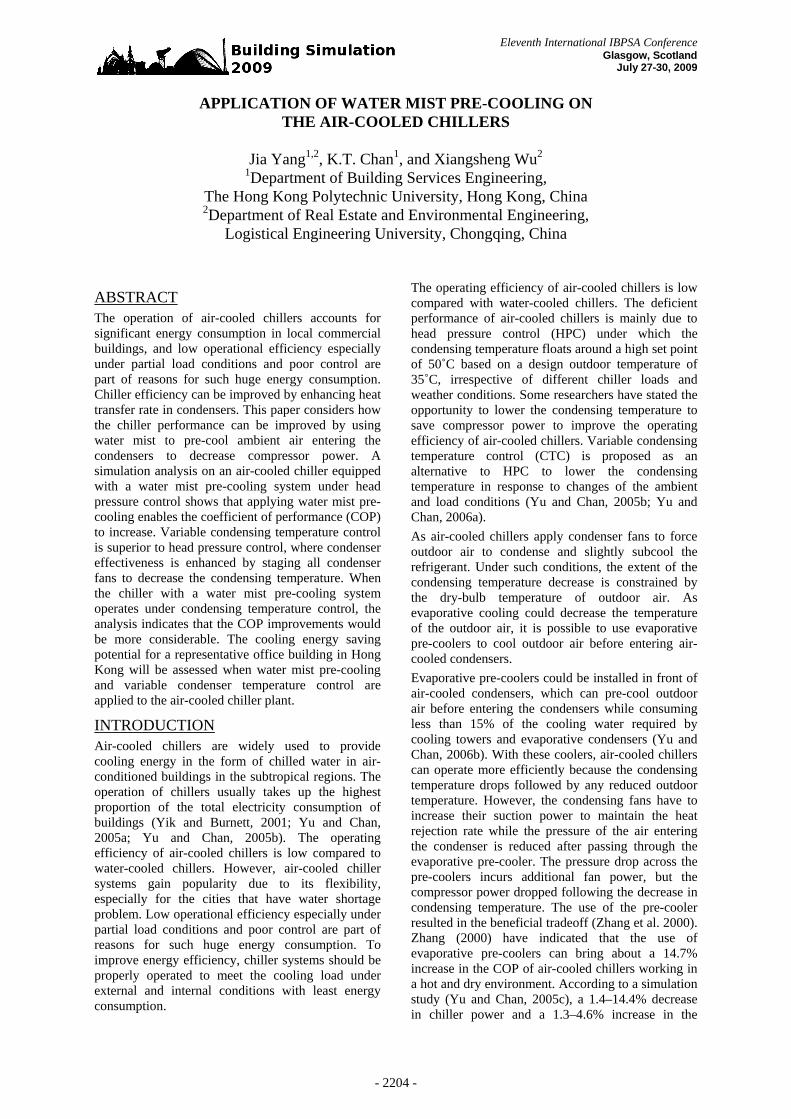
Figure 8 COP improvement at PLR of 0.9-1.0
Improvement in chiller efficiency under Scheme B When the Scheme B is applied, the percentage change of COP compared with Scheme A is shown in Figure 9, under which condition there is no water mist precooling.
-10%
10%
30%
50%
70%
90%
0.0 0.2 0.4 0.6 0.8 1.0PLR
CO
P im
prov
emen
t
Figure 9 COP improvement comparison Scheme A
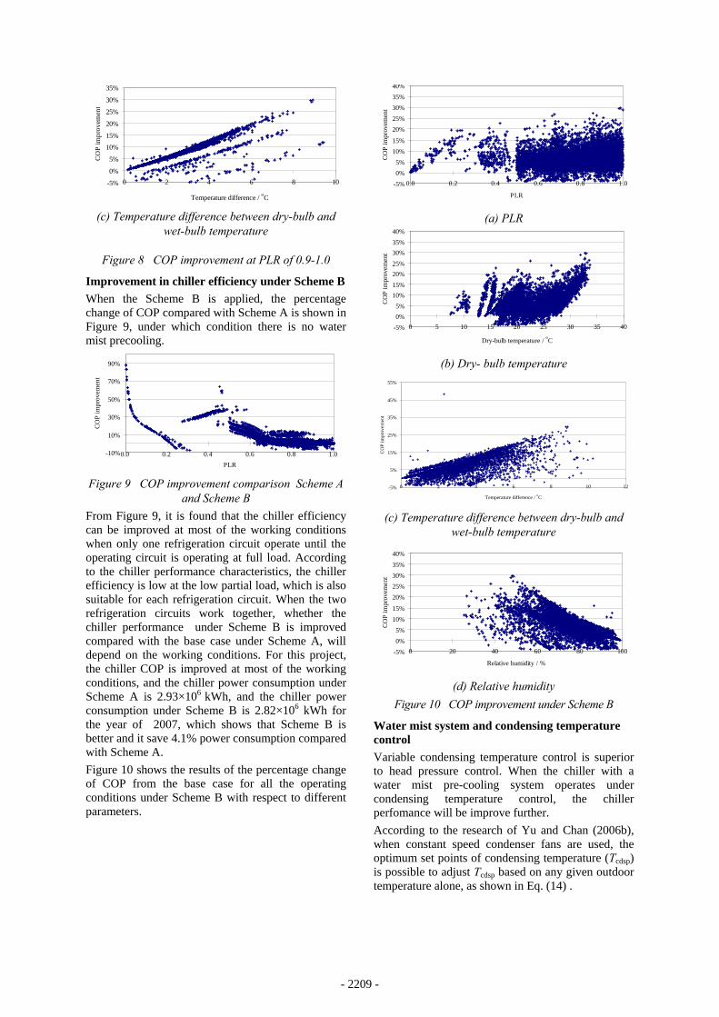
and Scheme B From Figure 9, it is found that the chiller efficiency can be improved at most of the working conditions when only one refrigeration circuit operate until the operating circuit is operating at full load. According to the chiller performance characteristics, the chiller efficiency is low at the low partial load, which is also suitable for each refrigeration circuit. When the two refrigeration circuits work together, whether the chiller performance under Scheme B is improved compared with the base case under Scheme A, will depend on the working conditions. For this project, the chiller COP is improved at most of the working conditions, and the chiller power consumption under Scheme A is 2.93×10⁶ kWh, and the chiller power consumption under Scheme B is 2.82×10⁶ kWh for the year of 2007, which shows that Scheme B is better and it save 4.1% power consumption compared with Scheme A. Figure 10 shows the results of the percentage change of COP from the base case for all the operating conditions under Scheme B with respect to different parameters.
-5%0%5%
10%15%
20%25%30%35%40%
0.0 0.2 0.4 0.6 0.8 1.0
PLR
CO
P im
prov
emen
t
(a) PLR
-5%0%5%
10%15%20%25%30%35%40%
0 5 10 15 20 25 30 35 40
Dry-bulb temperature / oC
CO
P im
prov
emen
t
(b) Dry- bulb temperature
-5%
5%
15%
25%
35%
45%
55%
0 2 4 6 8 10 12
Temperature difference / oC
CO
P im
prov
emen
t
(c) Temperature difference between dry-bulb and
wet-bulb temperature
-5%0%5%
10%15%
20%25%30%35%40%
0 20 40 60 80 100
Relative humidity / %
CO
P im
prov
emen
t
(d) Relative humidity
Figure 10 COP improvement under Scheme B
Water mist system and condensing temperature control Variable condensing temperature control is superior to head pressure control. When the chiller with a water mist pre-cooling system operates under condensing temperature control, the chiller perfomance will be improve further. According to the research of Yu and Chan (2006b), when constant speed condenser fans are used, the optimum set points of condensing temperature (Tcdsp) is possible to adjust Tcdsp based on any given outdoor temperature alone, as shown in Eq. (14) .
- 2209 -

⎪⎩
⎪⎨⎧ ≤+
=otherwise C20
C15for C5
ocdae
oocdae
cdsp
TTT (14)
Figures 11 to 12 show the results of the percentage change of COP from baseline for all the operating conditions under Scheme A and B, respectively.
-5%
0%
5%
10%
15%
20%
25%
30%
35%
0.0 0.1 0.2 0.3 0.4 0.5 0.6 0.7 0.8 0.9 1.0
PLR
CO
P im
prov
emen
t
Figure 11 COP improvement under Scheme A with
water mist pre-cooling under CTC
-5%
0%
5%
10%
15%
20%
25%
30%
35%
0.0 0.2 0.4 0.6 0.8 1.0
PLR
CO
P im
prov
emen
t
Figure 12 COP improvement under Scheme B with
water mist pre-cooling under CTC
Discussion and result analysis From Figure 6 to Figure 12, it can be found that there is no clear correlation between COP improvement and PLR when water mist system is coupled with the air-cooled chiller. The dry-bulb temperature, wet-bulb temperature, temperature difference between dry- bulb and wet-bulb temperature, and the relative humidity have great influence on the cooling effect for the water mist system, no matter under Scheme A or B. In general, applying water mist system to air-cooled chiller can improve the COP of the chiller under most of the working conditions, as the water mist could lower the air temperature entering the condenser. The chiller COP could increase in varying degrees by up to 30%, though it could drop from baseline for some operating conditions. The reduction of the chiller COP was always associated with the excessive mist and no complete evaporation underwent, the surplus water droplet could fall down to the ground or be carried through the condenser coil, which may affect the heat transfer efficiency. The reduced COP may also be due to the extra pump power of the water mist system. Generally, applying water mist system for evaporative precooling to air-cooled chiller help reduce the chiller power consumption 7.3% or 8.2% in average compared with the base cases under Scheme A and B, respectively.
From these figures, it can be found that the temperature difference between dry-bulb and wet-bulb temperature has a great influence on the cooling effect of the water mist system, the COP improvement was nearly linear with the temperature difference between dry-bulb and wet-bulb temperature. The water mist system worked effectively when the temperature difference between the dry-bulb and wet-bulb temperature was larger than 3.5oC. Furthermore, the evaporation process occurs intensively when the outdoor temperature is high enough. The results obviously showed that the COP of the air-cooled chiller could be improved when the outdoor dry-bulb temperature was higher than 23oC. Since the water mist system cool down the outdoor temperature by evaporation, it is most effective when the moisture content in outdoor air is low, which can be shown in the figures related to relative humidity. The lower the relative humidity is, the more the COP improvement is, and the COP improvement is nearly reverse linear with the relative humidity.Therefore, operating the water mist system when the relative humidity is low should be the most efficient way to improve the COP of the air-cooled chiller. According to the supplier’s recommendation for the water mist system operation ( dhT > 28oC and RH<
77%) , it is definite to improve the air-cooled chiller efficiency under such conditions. The simulation results show that that energy savings from water mist pre-cooling would be more significant if the chillers operate in a hot and arid outdoor environment. Variable condensing temperature control is superior to head pressure control, when the chiller with a water mist pre-cooling system operates under condensing temperature control, the chiller perfomance will be improve further. Under Scheme A and B, the annual chiller energy saving is 16.2% or 15.8% compared with the base cases of Scheme A or B, respectively. Under condensing temperature control, the heat rejection airflow is generally kept at its maximum level under many operating conditions, then full vaporization process of water mist can occur more often, and the air temperature decrease more, so as to improve the chiller COP further. There were two identical water mist installations for each chiller, each with a high pressure pump and dedicated to one refrigeration circuit. The mist systems were designed to provide a total mist generation rate of 0.067 l/s, and all the mist generated are fully vaporized by the air entering the condenser. It is noted that the water consumption rate of 0.067 l/s is very small, compared with 0.93 l/s required for a hypothetical cooling tower serving the chiller, which is specified in Standard 550/590 (2003). So the amount of water for mist generation is negligible, and the water mist pre-cooling has a great advantage over the cooling tower in terms of the water consumption.
- 2210 -

CONCLUSION This paper presents the effect of operating water mist system to enhance the performance of air-cooled chillers under various operating conditions. Generally, applying water mist system to air-cooled chiller can improve the COP of the chiller under most of the working conditions, as the water mist could lower the air temperature entering the condenser. A chiller model is established and validated according to the operating data, then the cooling effect of the water mist precooling is assessed based on this chiller model. As the chiller has two refrigeration circuits, there are three operating modes for each chiller, and two control strategies are considered in this paper. Under the two control strategies, the same results can be obtained. The application of water mist pre-cooling could increas the COP in various degrees by up to 30%, especially when the relative humidity is low and the temperature difference between the dry-bulb and wet-bulb temperature is considerable. For the annual chiller power consumption, the chiller power can reduce by 7.3% or 8.2% compared with the base cases of Scheme A and B, respectively. Variable condensing temperature control is superior to head pressure control, where condenser effectiveness is enhanced by staging all condenser fans to decrease the condensing temperature. It is worth investigating how the use of water mist pre-cooling can complement CTC to further enhance the COP of air-cooled chillers. When CTC replaced HPC with the water mist system, the chiller power could reduce by 16.2% or 15.8% for the annual energy consumption under Scheme A and B, respectively. In this study, the potential of applying mist pre-cooling have been investigated for air-cooled chillers operating in subtropical regions. The cooling effect will be better and energy savings from water mist pre-cooling would be more significant if the chillers operate in a hot and arid outdoor environment.The findings in this study gave an idea on how the water mist system can be used as an evaporative pre-cooler to improve the chiller efficiency under different weather and cooling load conditions. The operating data of the chiller system coupled with water mist system will be measured by conducting further experiments, so as to validate the chiller model coupled with water mist system.The optimal operation of water mist system under CTC will be the future research work to improve the chiller efficiency.
ACKNOWLEDGEMENT The work described in this paper was supported by a grant from the central research grant of The Hong Kong Polytechnic University, Project Code: RP1R.
REFERENCES Air-conditioning & Refrigeration Institute, Standard
550/590: Performance rating of water chilling
packages using the vapour compression cycle, Air-conditioning & Refrigeration Institute, Arlington, Virginia, 2003.
Bourdouxhe JP, Grodent M, Lebrun JJ, Saavedra C, Silva KL. A toolkit for primary HVAC system energy calculation—part 2: reciprocating chiller models. ASHRAE Trans 1994; 100(2):774–86.
Chan K.T. and Chow W.K.. Energy impact of commercial-building envelopes in the sub-tropical climate, Applied Energy, 1998, 60(1): 21-39.
F.W. Yu and K.T. Chan, Life cycle analysis of enhanced condenser features for air-cooled chillers serving air-conditioned buildings, Building and Environment 41 (2006a), 981–991.
F.W. Yu and K.T. Chan, Improved condenser design and condenser-fan operation for air-cooled chillers, Applied Energy 83 (2006b), 628-648.
CC Hsieh, SC Yao, Evaporative heat transfer characteristics of a water spray on micro-structured silicon surfaces. Int. J. Heat Mass Transfer 49 (2006), 962–974.
S.D.M. Jones and W.M. Robertson, The effects of spray-chilling carcasses on the shrinkage and quality of beef, Meat Sci 24 (1988), 177–188.
Solar Energy Laboratory. TRNSYS: A Transient System Simulation Program (Reference Manual). Madison, WI: University of Wisconsin/Madison Press, 2000.
Turnbull, A., Water mist demystified. Industrial Fire Journal, England, 2006 (September): 41-46.
Yik, F. W. H., Burnett, J. and Prescott, I. Predicting air-conditioning energy consumption of a group of buildings using different heat rejection methods. Energy and Buildings, 33(2001), 151-166.
Yu, F. W. and Chan, K. T., Electricity end-use characteristics of air-cooled chillers in hotels in Hong Kong. Building and Environment, 40(2005a), 143-151.
Yu, F. W. and Chan, K. T., Advanced control of condensing temperature for enhancing the operating efficiency of air-cooled chillers. Building and Environment, 40(2005b), 727-737.
Yu, F. W. and Chan, K. T., Application of direct evaporative coolers for improving the energy efficiency of air-cooled chillers, Journal of Solar Energy Engineering 127 (3) (2005c), 430–433.
Zhang, H., You, S.J., Yang, H. X., and Niu, J, L., Enhanced Performance of Air-Cooled Chillers Using Evaporative Cooling, Build. Services Eng. Res.Technol, 21(2000), 213-217.
- 2211 -