Embed Size (px)
Citation preview
Energy and Environment Research; Vol. 5, No. 1; 2015 ISSN 1927-0569 E-ISSN 1927-0577
Published by Canadian Center of Science and Education
18
Application of Waste Plastic Pyrolysis Oil in a Direct Injection Diesel Engine: For a Small Scale Non-Grid Electrification
Sunbong Lee1, Koji Yoshida2 & Kunio Yoshikawa1,2 1 Department of Environmental Science and Technology, Interdisciplinary Graduate School of Science and Engineering, Tokyo Institute of Technology, Kanagawa, Japan 2 Department of Mechanical Engineering, College of Science and Technology, Nihon University, Tokyo, Japan
Correspondence: Sunbong Lee, Department of Environmental Science and Technology, Tokyo Institute of Technology, Kanagawa, Japan. Tel: 81-09-6526-4541. E-mail: [email protected]
Received: November 26, 2014 Accepted: December 22, 2014 Online Published: March 9, 2015
doi:10.5539/eer.v5n1p18 URL: http://dx.doi.org/10.5539/eer.v5n1p18
Abstract Waste plastic can be transformed to oil by the pyrolysis and it may be applicable as a fuel for diesel engines. The pyrolysis oil property varies depending on the raw waste plastic and the pyrolysis condition, which is different from that of diesel and gasoline. Considering the thermal efficiency, the running stability and the reliability, diesel engines are the most promising energy converter to generate electricity by using the pyrolysis oil. In this research, plastics from municipal wastes were converted into oil through the pyrolysis and the catalytic reforming process in a commercial facility. Compared with diesel fuel, the raw pyrolysis oil showed slightly lower kinematic viscosity than the minimum level of diesel fuel and almost the same heating value. Its carbon class differed from diesel, gasoline and kerosene and is mainly composed of naphethenes and olefins which have poor self-ignition quality. The pyrolysis oil was blended with diesel fuel with different mixing ratios. A single cylinder small size direct injection diesel engine was used for the test. The full load performance, the exhaust emissions and the thermal efficiency were investigated from the view point of the compatibility to diesel fuel based on the US EPA regulation mode.
Keywords: waste plastic, pyrolysis, blend, direct injection diesel engine, exhaust emissions
1. Introduction The population which could not access to electricity was around 1.2 billion in 2010 and is distributed in many low developing countries such as African, South Central Asia and Southeast Asia/Pacific (World Energy Council, 2013). With the increase in the population and the economic growth in those countries (United Nations, 2012), waste generation is growing rapid especially for the organic and the plastic and the uncontrolled waste disposal is becoming more serious issues to manage it (Daniel, H., 2012). The interest on Waste to Energy is growing by the above drivers (Luca, Lo Re L., 2013). Among them, waste plastic can be converted into oil and gas by the pyrolysis and the catalytic reforming process. The pyrolysis oil has almost the same heating value with petroleum fuels because plastic material is originated from crude oil. The chemical and physical properties of the pyrolysis oil are highly depending on the raw waste plastic. Considering the various oil properties, diesel engine is the most appropriate energy converter in the point of stable engine running as well as the high electricity generation efficiency. Actually, it is unclear whether the pyrolysis oil can be used in diesel engines as 100% alternative fuel or it needs blending with diesel fuel.
The oil from the scrap-tire thermal-mechanical pyrolysis was run on a single cylinder diesel engine using automotive diesel fuel and two mixtures of the diesel fuel and the tire pyrolysis oil (TPO) with the volume ratio of 20% TPO and 40% TPO due to the lower cetane index of TPO. The 20% mixture of TPO and the diesel fuel showed no significant differences for power, fuel consumption and exhaust gas emissions (Stefano, F., 2013). The shredded PVC (Polyvinyl chloride) and PET (Polyethyelene terephthalate) bottle plastics was pyrolyzed in the laboratory scale pyrolysis device and the pyrolysis oil was mixed with diesel fuel using a ultrasonic vibrator due to the high kinematic viscosity around 3 times than that of diesel. The blend oil of diesel with 5% volume fraction ot the waste plastic pyrolysis oil was tested in a single cylinder diesel engine at 50% load of the engine maximum power output and resulted in a slight improvement of the fuel consumption (Senthilkumar, T., 2012). Plastic waste was converted into liquid oil by using the pyrolysis process including the catalytic cracking with
www.ccsenet.org/eer Energy and Environment Research Vol. 5, No. 1; 2015
19
the pre-treatment of the shredding. A blend of 50% and 70% with the pyrolysis oil by volume in the diesel fuel were evaluated for the thermal efficiency and the exhaust gas emissions by operating a single cylinder diesel engine at its maximum engine output speed with varying the engine load and showed the higher thermal efficiency and the higher gas emission for CO (Carbon monoxide) and THC (Total hydroCarbon) emission (Rajesh, G., 2011). Mukherjee et al (Kaustav, M., 2014) produced the waste plastic oil via the pyrolyzer without the catalytic process and blended with the diesel fuel and the ethanol by the ratio of 20, 40 and 60% and tested in a direct injection twin cylinder diesel engine at the rated engine speed by changing the engine load. They concluded that the 20% blend oil has characteristics as close to diesel regarding to the thermal efficiency, NOx (Nitrogen oxides) and CO emission. Pratoomyod et al (Jane, P., 2013) carried out the operation test in a direct injection 6-cylinder diesel engine by using the blend oil which was diesel blended with the waste plastic oil with the ratio of 25%, 50% and 75% by volume. The engine operation point was ranged from the two thirds of the rated engine speed to the idle speed at a certain interval on the 100% load. The specific fuel consumption, the CO and the THC emissions were higher than diesel operation and the NO emission increased with the increase in the blend ratio. Several research results were reviewed by Patel et al (Nilamkumar, S, P., 2013) and Harshal et al (Pawar, Harshal R., 2013) about the usage of the blended waste plastic pyrolysis oil with diesel fuel in the diesel engine on the engine operation range which was specified by the researchers.
As reviewed above, the literatures have been highly evaluated academically and been thought to be somewhat limited in the view of the real world adaption of the pyrolysis oil into the diesel engine. The production facility of the raw pyrolysis oil was the laboratory scaled facility or undefined specifically. Engine operation points for the experiment were decided by the view of researchers based on their knowledges and experiences. For the evaluation of the experimental result, the exhaust emissions from the combustion of the pyrolysis oil in the diesel engine were qualitatively compared with those of diesel fuel.
This research was carried out for aiming to the real world adaption mainly for electricity generation. For the sake of it, the pyrolysis oil which was produced in a commercial plant was applied to a small direct injection diesel engine. The compatibility of the pyrolysis oil to diesel fuel was investigated with regard to the full load performance, the exhaust emissions and the thermal efficiency according to the US EPA emission test mode.
2. Materials and Methods 2.1 Production of Waste Plastic Pyrolysis Oil
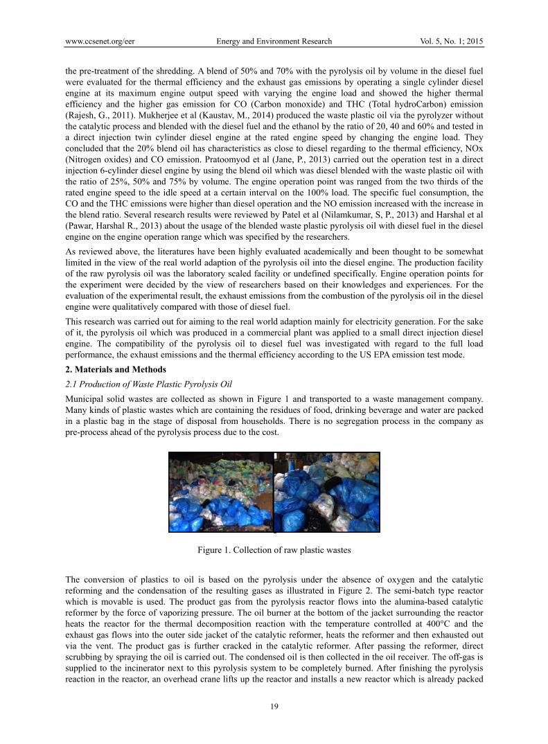
Municipal solid wastes are collected as shown in Figure 1 and transported to a waste management company. Many kinds of plastic wastes which are containing the residues of food, drinking beverage and water are packed in a plastic bag in the stage of disposal from households. There is no segregation process in the company as pre-process ahead of the pyrolysis process due to the cost.
Figure 1. Collection of raw plastic wastes
The conversion of plastics to oil is based on the pyrolysis under the absence of oxygen and the catalytic reforming and the condensation of the resulting gases as illustrated in Figure 2. The semi-batch type reactor which is movable is used. The product gas from the pyrolysis reactor flows into the alumina-based catalytic reformer by the force of vaporizing pressure. The oil burner at the bottom of the jacket surrounding the reactor heats the reactor for the thermal decomposition reaction with the temperature controlled at 400°C and the exhaust gas flows into the outer side jacket of the catalytic reformer, heats the reformer and then exhausted out via the vent. The product gas is further cracked in the catalytic reformer. After passing the reformer, direct scrubbing by spraying the oil is carried out. The condensed oil is then collected in the oil receiver. The off-gas is supplied to the incinerator next to this pyrolysis system to be completely burned. After finishing the pyrolysis reaction in the reactor, an overhead crane lifts up the reactor and installs a new reactor which is already packed

www.ccsenet.org/eer Energy and Environment Research Vol. 5, No. 1; 2015
20
with the feedstock and the whole process starts again.
Figure 2. Pyrolysis process of the commercial plant
2.2 Test Fuels
Table 1 shows the hydrocarbon composition analysis and the physical property of the raw pyrolysis oil and diesel fuel, respectively. The raw pyrolysis oil shows almost the same chemical content in carbon and hydrogen except oxygen. It is inferred that the oxygen in the pyrolysis oil came from the contamination of the raw plastic wastes by food and drinking residues in the stage of consumer disposal. The amount of oxygen is low enough and can be neglected as one of the effective factors influencing the engine performances. The density and the kinematic viscosity are lower than those of diesel fuel. The density of the pyrolysis oil may affect the full load performance. The kinematic viscosity undergoes slightly less than the minumue value of the diesel fuel in the United States (ASTM D975). When the raw pyrolysis oil is directly used in diesel engines without any treatments, it would be concerned in terms of the lubricity in the fuel delivery and the injection system of diesel engines (Lacey, P., I., 1992). The heating value is almost the same as diesel due to the similar content of hydrocarbon as stated above.
Table 1. Composition analysis
Composition analysis
%wt/wt Diesel[JIS2]
Raw pyrolysis-oil[Waste plastic]
C 85.04 85.87 H 13.55 13.71 N 0 0 S 0 0 O 0 0.421 Physical property Density [kg/cm3] 0.83 0.75 Kinematic viscosity [mm2/s] 2.744 1.19 Water content [%wt/wt] 0 0 Low Heat value [MJ/kg] 45 45.4
Figure 3 illustrates the carbon atom number distribution of the pyrolysis oil obtained from the commercial plant. The raw pyrolysis oil was analyzed by GC-MS analyzer to compare the distribution of hydrocarbon atom to that of diesel. The carbon number distribution of the oil product from the commercial plant was obviously shifted from the hydrocarbon range of diesel. The large fraction of hydrocarbon was found in the range of 6-14, which is much lighter than diesel and is close to the range of gasoline. It reached the maximum fraction at the carbon number of 11. In contrast, the hydrocarbon range of diesel was in the carbon number of 8-25 and the highest fraction is seen at 17. The fractions of carbon atom number from both oils are totally different.

www.ccsenet.org/eer Energy and Environment Research Vol. 5, No. 1; 2015
21
Figure 3. Carbon number distribution
The carbon class of the diesel fuel and the raw pyrolysis oil is illustrated in Figure 4. Comparing to diesel, the content of n-Alkanes which is good for self-ignition in compression ignition engine is very low by around 25%. Aromatic is one of important factors affecting the level of the particulate matter emission from diesel engines (World Wide Fuel Chart, 2006) and is very low. The shape of the carbon class distribution of the raw pyrolysis oil is not like kerosene/jet oil (The American Petroleum Institute Petroleum HPV Testing Group, 2010) and gasoline (Robert A. H. 2004). It mainly consists of iso-alkanes, n-alkanes and olefins in % area of 27%, 25% and 9% respectively. Over 30% content was not able to be defined due to its complicated chemical bond structure. Aromatics, Cyclo-alkanes (Naphthenes), isoalkanes and olefins which are not good for the self-ignition quality (Prasenjeet G., 2006) in compression ignition engine compose around 40%. From this analysis, it can be estimated that the raw pyrolysis oil has very poor self-ignition quality. Thus, the raw pyrolysis oil was mixed with diesel fuel. The mixing ratio was 20, 40, 60 and 80% where the number was the volume percentage of the raw pyrolysis oil to the diesel fuel. In the engine experiment, low mixing ratio blend oil was tried first considering the poor self-ignition quality. By blending, the physical property of the raw pyrolysis oil was improved as shown in Figure 5.
Fugure 4. Hydrocarbon classes
Figure 5. Density and kinematic viscosity with blending ratio (0% : diesel)
0.70
0.74
0.78
0.82
0.86
0.90
0 20 40 60 80 100
De
nsi
ty, g
/cm
3
Blending ratio, %
0.00
1.00
2.00
3.00
4.00
0 20 40 60 80 100
Kin
em
atic
vis
cosi
ty, m
m2/
s
Blending ratio, %
0
3
6
9
12
15
18
21
24
4 6 8 10 12 14 16 18 20 22 24 26 28
Chro
mat
ogra
m a
rea,
%Are
a
Carbon number, -
Diesel(JIS2)Pyrolysis oil
0
10
20
30
40
50
60
70
80
90
Chro
mat
ogra
m ar
ea, %
Area Pyrolysis oil
Diesel(JIS2)
www.ccsenet.org/eer Energy and Environment Research Vol. 5, No. 1; 2015
22
2.3 Test Engine
For the engine test, a single cylinder direct fuel injection diesel engine was used and Table 3 shows the engine specification (Koji Y., 2010) (Hiroshi, M., 1999). The engine is very small and turns out a low engine output. The combustion chamber shape was a re-entrant type. The fuel injection timing was 17.5±0.5 degree BTDC CA (Bottom top dead center crank angle) and the injection fuel pressure was 20 MPa, built by the mechanical fuel delivery pump for all tests.
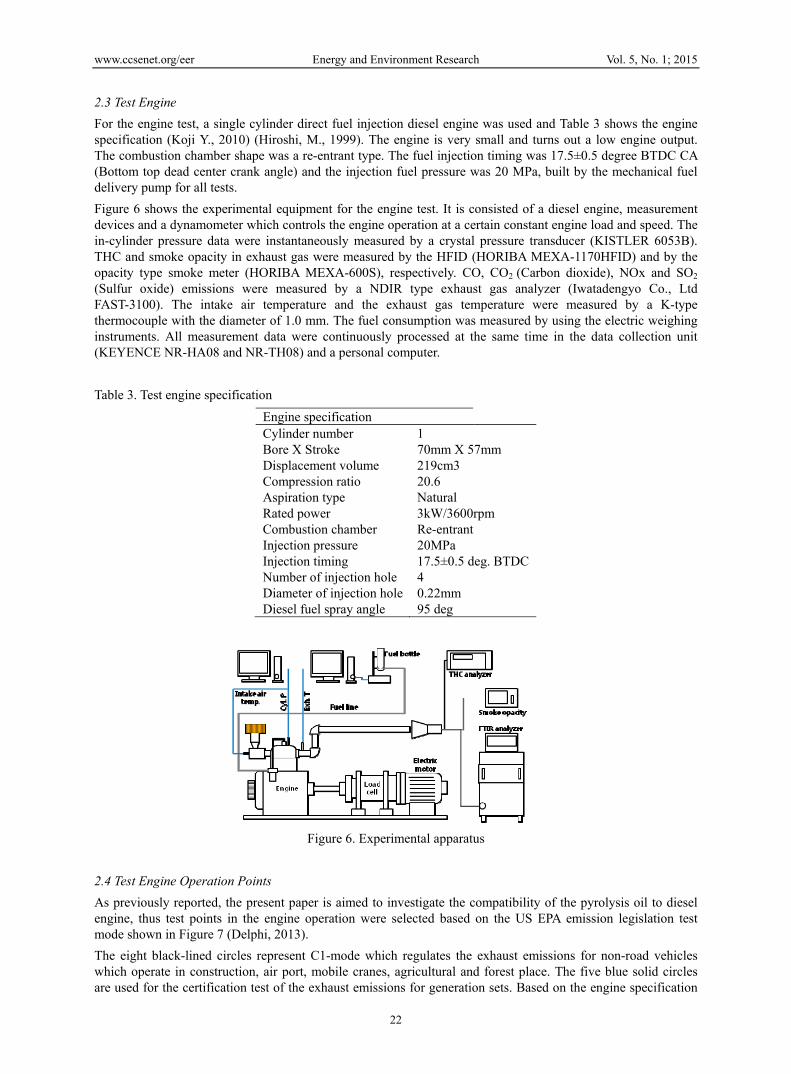
Figure 6 shows the experimental equipment for the engine test. It is consisted of a diesel engine, measurement devices and a dynamometer which controls the engine operation at a certain constant engine load and speed. The in-cylinder pressure data were instantaneously measured by a crystal pressure transducer (KISTLER 6053B). THC and smoke opacity in exhaust gas were measured by the HFID (HORIBA MEXA-1170HFID) and by the opacity type smoke meter (HORIBA MEXA-600S), respectively. CO, CO2 (Carbon dioxide), NOx and SO2 (Sulfur oxide) emissions were measured by a NDIR type exhaust gas analyzer (Iwatadengyo Co., Ltd FAST-3100). The intake air temperature and the exhaust gas temperature were measured by a K-type thermocouple with the diameter of 1.0 mm. The fuel consumption was measured by using the electric weighing instruments. All measurement data were continuously processed at the same time in the data collection unit (KEYENCE NR-HA08 and NR-TH08) and a personal computer.
Table 3. Test engine specification
Engine specification Cylinder number 1 Bore X Stroke 70mm X 57mm Displacement volume 219cm3 Compression ratio 20.6 Aspiration type Natural Rated power 3kW/3600rpm Combustion chamber Re-entrant Injection pressure 20MPa Injection timing 17.5±0.5 deg. BTDCNumber of injection hole 4 Diameter of injection hole 0.22mm Diesel fuel spray angle 95 deg
Figure 6. Experimental apparatus
2.4 Test Engine Operation Points
As previously reported, the present paper is aimed to investigate the compatibility of the pyrolysis oil to diesel engine, thus test points in the engine operation were selected based on the US EPA emission legislation test mode shown in Figure 7 (Delphi, 2013).
The eight black-lined circles represent C1-mode which regulates the exhaust emissions for non-road vehicles which operate in construction, air port, mobile cranes, agricultural and forest place. The five blue solid circles are used for the certification test of the exhaust emissions for generation sets. Based on the engine specification

www.ccsenet.org/eer Energy and Environment Research Vol. 5, No. 1; 2015
23
shown in Table 3, the engine speed was set to 1500rpm for the idle, 2450rpm for the intermediate and 3500rpm for the rated. The rated engine speed was slightly reduced from its original rated power producing speed, 3600rpm. The 100% power output at the intermediate and the rated engine speed was controlled by conducting the full delivery of the fuel in the injection system for all tested fuels. It means that no additional throttle opening was done to compensate the full load engine output depending on the fuel types. All powers in the partial load operation points were controlled to produce the output powers which were designated to the mode points. When evaluating the experimental results, R25 (25% load at the rated speed) data were interpolated between 50% and 10% because the linearity was shown to be enough.
Fugure 7. Test engine operation points
3. Results and Discussion 3.1 Full Load Performance
Full load performance was evaluated upon 100% diesel which is expressed as the blend ratio 0% point on the horizontal axis and the two blend oils, the 20% and 40% blending ratios. For all the full load tests, the throttle position was fully opened as mentioned above. The maximum reachable torque is shown in Figure 8 indicating that it was drastically decreased with the increase of the blend ratio.
Figure 8. Maximum reachable torque (left) and standard deviation of the torque (right) as a function of the blend ratio (0: 100% diesel)
Up to the 20% blend ratio, comparable engine running was achieved even though the full load output was declined about 13% at 2450rpm and 17% at 3500rpm. The running stability was observed in the same level for the intermediate engine speed and became worse at the rated speed but it was acceptable level because the engine operation was continued without any troubles. For the 40% blend oil, the maximum torque dropped around 37% at the intermediate speed and 56% at the rated speed which corresponds to the R50 output of diesel. The engine operation stability which is expressed by the standard deviation of the torque depicted in Figure 8 (right one) became worse with increasing the blend ratio and in the case of the 40% blend oil at 3500rpm, the engine could keep running only for a few minutes.
The heat value of the raw pyrolysis oil is almost identical with the diesel fuel and this means there is no change
2.0
3.0
4.0
5.0
6.0
7.0
8.0
9.0
0 10 20 30 40 50
Torq
ue, N
m
Blend ratio, %
2450 rpm
3500 rpm
0.0
0.2
0.4
0.6
0.8
0 10 20 30 40 50
Sta
ndar
d de
v. o
f tor
que
, Nm
Blend ratio, %
2450 rpm
3500 rpm

www.ccsenet.org/eer Energy and Environment Research Vol. 5, No. 1; 2015
24
in the heat value by blending the pyrolysis oil with diesel fuel. Nevertheless, the torque of those blend oils dropped and some analysis is followed.
For the case of I100 operation point, the injection quantity decreased 5.8mg/st (-8%) for the blend 20% and 4.6mg/st (-27%) for the blend 40% comparing to 6.3mg/st of diesel fuel with increasing the blend ratio as shown in Figure 9. It is thought that the physical property of the raw oil such as lower density and kinematic viscosity affected the injection amount (Desantes, J., M., 2003) (Qaisar, H., 2013). The density drops, 5.3% for the blend 20% and 5.9% for the blend 40% as shown in Figure 4, can not cover all the injection amount drops. In the event of the injection, the rate of injection might be additionally reduced by the lower kinematic viscosity (Chang, C. T., 1997). The relationship between the injected amount to the torque can be simply calculated by dividing the engine torque by the injection quantity. The fuel mass to torque conversion factor is around 1.1 Nm/[mg/st] for the diesel shown in Figure 9. For the 20% blending oil, 6.8Nm can be estimated by using the conversion factor and the injection mass of 5.8mg/st which was fully delivered by the pump but the actual torque gained was 6.2Nm (8% lower). For the 40% blend oil, the calculated torque is 5.2Nm and the actual was 4.5Nm (27% lower).
Figure 9. Torque and injection quantity as a function of the blend ratio at I100, 2450rpm
Figure 10. Cylinder pressure and rate of heat release at I100, 2450rpm
For both blend oils, the actual torque output was less than the estimated ones and this went worse with increasing the blend ratio. This can be explained based on the combustion analysis as depicted in Figure 10. In the premixed combustion (John, B., H., 1988) (Johann, H., 2013) (Horn, U., 2007) where the fuel-air mixture which was accumulated during the ignition delay defined as duration between the injection timing shown in Table 3 and the first rise of the heat release rate (Carroll E. G., 1998) (Ghojel, J., 2005) rapidly exploded, the cylinder pressure rise was slower due to the lower injection rate caused by the physical oil property as described above. The ignition delay became longer with increasing the blending ratio. The enlarged ignition delay is caused by the chemical property of the raw pyrolysis oil based on the analysis result shown in Figure 4. For the 20% blending ratio, even though the ignition timing was slightly delayed, the amount of the heat release in the premixed combustion phase was lower than for the diesel and the phase was slightly shifted backward. As a result, the torque dropped more than the estimated one. This might be caused by mainly the lower injection rate due to the
0
1
2
3
4
5
6
7
-20 -10 0 10 20 30 40
Cyl
inde
r Pre
ssur
e, M
Pa
Crank angle, deg.
I100/2450 rpm DieselWPO 20%WPO 40%
-5
0
5
10
15
20
25
30
35
-20 -10 0 10 20 30 40
Rat
e of
Hea
t Rel
ease
, J/
deg
Crank angle, deg.
I100/2450 rpm DieselWPO 20%WPO 40%

www.ccsenet.org/eer Energy and Environment Research Vol. 5, No. 1; 2015
25
physical property of the raw pyrolysis oil. For the 40% blending ratio, the ignition delay was significantly enlarged and the premixed heat release phase was moved more than that of the 20% blend. Thus the larger torque drop than the calculated one was caused mainly by the ignition delay due to the chemical property of the raw pyrolysis oil.
The identical analysis can be basically propagated for the case of R100 operation point. The injection quantity of the diesel fuel increased more than that of I100 due to the increased pressure build-up driven by the higher engine speed and the injection quantity of 6.9mg/st produced the torque of 8.3Nm and the torque conversion factor was 1.2Nm/[mg/st] as illustrated in Figure 11. The estimated torque was 7.6Nm for the 20% blending and 5.4Nm for the 40% blending. The actual torque deteriorated by -9% and -35%, respectively. Those numbers are even larger especially for the 40% blend than those of the I100. For the 20% blending, the amount of the heat release in the premixed combustion phase decreased slightly than that of I100 shown in Figure 12. For the 40% blend, the heat release phase delayed more by greatly enlarged ignition timing due to the higher piston speed and this led the magnitude of the actual torque drop to the calculation to be larger than the case of I100. The ignition delay will be summarized later including part loads.
Figure 11. Torque and injection quantity as a function of the blend ratio at R100, 3500rpm
Figure 12. Cylinder pressure and rate of heat release at R100, 3500rpm
3.2 Exhaust Emissions
The concentration based exhaust emissions in the experiment was processed to weight based ones using the carbon balance and the fuel consumption so that the compatibility of the pyrolysis oil to diesel can be evaluated according to the US EPA regulation. The US EPA defines the Tier1 regulation as 10g/kWh of NOx+NMHC (Non Methane HydroCarbon), 8g/kWh of CO and 1g/kWh of PM (Partuculate matters) for the test engine category (EPA) using the test mode described in the section 2.4. The regulation emission numbers were used as just reference value in the report. For the PM, the smoke opacity was converted to the mass value (Diesel-net) only for the R100 operation point.
Figure 13 shows the result of the exhaust emissions for the intermediate engine speed, 2450rpm. The NOx emission was not changed in overall by the 20% blending and tended to decrease for the 40% blending. For the
0
1
2
3
4
5
6
7
-20 -10 0 10 20 30 40
Cyl
inde
r Pre
ssur
e, M
Pa
Crank angle, deg.
R100/3500 rpm DieselWPO 20%WPO 40%
-5
0
5
10
15
20
25
30
35
-20 -10 0 10 20 30 40
Rat
e of
Hea
t Rel
ease
, J/
deg
Crank angle, deg.
R100/3500 rpm DieselWPO 20%WPO 40%
www.ccsenet.org/eer Energy and Environment Research Vol. 5, No. 1; 2015
26
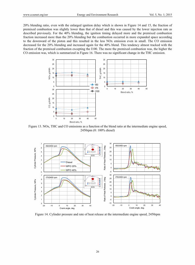
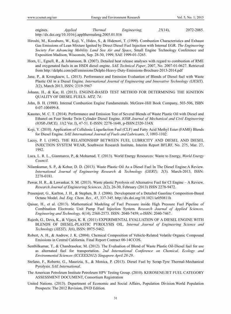
20% blending ratio, even with the enlarged ignition delay which is shown in Figure 14 and 15, the fraction of premixed combustion was slightly lower than that of diesel and this was caused by the lower injection rate as described previously. For the 40% blending, the ignition timing delayed more and the premixed combustion fraction increased more than the 20% blending but the combustion occurred in more expanded space according to the downward of the piston and this resulted in the less NOx emission even in small. The CO emission decreased for the 20% blending and increased again for the 40% blend. This tendency almost tracked with the fraction of the premixed combustion excepting the I100. The more the premixed combustion was, the higher the CO emission was, which is summarized in Figure 16. There was no significant change in the THC emission.
Figure 13. NOx, THC and CO emissions as a function of the blend ratio at the intermediate engine speed, 2450rpm (0: 100% diesel)
Figure 14. Cylinder pressure and rate of heat release at the intermediate engine speed, 2450rpm
0
1
2
3
4
5
6
7
-20 -10 0 10 20 30 40
Cyl
inde
r Pre
ssur
e, M
Pa
Crank angle, deg.
I50/2450 rpm
0
1
2
3
4
5
6
7
-20 -10 0 10 20 30 40
Cyl
inde
r Pre
ssur
e, M
Pa
Crank angle, deg.
I75/2450 rpm
-5
0
5
10
15
20
25
30
-20 -10 0 10 20 30 40
Rat
e of
Hea
t Rel
ease
, J/
deg
Crank angle, deg.
I50/2450 rpm
-10
-5
0
5
10
15
20
25
30
-20 -10 0 10 20 30 40
Rat
e of
Hea
t Rel
ease
, J/
deg
Crank angle, deg.
I75/2450 rpm
Diesel
WPO 20%
WPO 40%
0
5
10
15
20
25
30
0 10 20 30 40 50
NO
x, g
/kW
h
Blend ratio, %
0
5
10
15
20
25
30
0 10 20 30 40 50
THC, g
/kW
h
Blend ratio, %
0
5
10
15
20
25
30
0 10 20 30 40 50
CO
, g/k
Wh
Blend ratio, %
I50I75I100

www.ccsenet.org/eer Energy and Environment Research Vol. 5, No. 1; 2015
27
Figure 15. Ignition delay and premixed combustion fraction as a function of the blend ratio at the intermediate engine speed, 2450rpm (0: 100% diesel)
Figure 16. The effect of the premixed combustion fraction on the CO emission at the intermediate engine speed, 2450rpm (0%: diesel)
At the rated engine speed, the NOx emission was almost identical tendency with the result of the intermediate engine speed but decreased around double in the 40% blending for R10 (Figure 17) due to the much longer ignition delay as shown in Figure 18 and 19. The THC and CO emissions increased with the increase of the blending ratio at a very low load such as R10. For the 40% blending, the ignition delay was not different from those of the intermediate speed but the ignition timing was too much retarded according to the increase of the engine speed to keep the stable engine operation for the R10 and R50. The PM emission for the 20% blending was slightly higher but the absolute number was far less the EPA regulation, 1g/kWh. In Figure 20, the impact of the premixed combustion fraction on the CO emission is depicted and almost the same tendency as seen in I100 is found
Figure 17. NOx, THC and CO emissions as a function of the blend ratio at the rated engine speed, 3500rpm. (0%: diesel)
0
5
10
15
20
25
30
0 10 20 30 40 50
NO
x, g
/kW
h
Blend ratio, %
0
10
20
30
40
0 10 20 30 40 50
THC, g
/kW
h
Blend ratio, %
0
20
40
60
80
0 10 20 30 40 50
CO
, g/k
Wh
Blend ratio, %
0.0
0.2
0.4
0.6
0.8
1.0
0 10 20 30 40 50
PM
, g/k
Wh
Blend ratio, %
R10R50R75R100
20
40
60
80
100
0 10 20 30 40 50
Pre
mix
ed com
bust
ion, %
Blend ratio, %
0
5
10
15
20
25
30
0 20 40 60 80
CO
, g/k
Wh
Blend ratio, %
I50I75I100
I50I75I100

www.ccsenet.org/eer Energy and Environment Research Vol. 5, No. 1; 2015
28
Figure 18. Cylinder pressure and rate of heat release as a function of the blend ratio at the rated engine speed, 3500rpm
Figure 19. Ignition delay and premixed combustion fraction as a function of the blend ratio at the intermediate engine speed, 3500rpm (0%: diesel)
Figure 20. The effect of the premixed combustion fraction on the CO emission at the intermediate engine speed, 2500rpm (0%: diesel)
0.40
0.45
0.50
0.55
0.60
0.65
0.70
0 10 20 30 40 50
Ignitio
n d
elay
, ms
Blend ratio, %
20
40
60
80
100
0 10 20 30 40 50
Pre
mix
ed com
bust
ion, %
Blend ratio, %
0
1
2
3
4
5
6
-20 -10 0 10 20 30 40
Cyl
inde
r Pre
ssur
e, M
Pa
Crank angle, deg.
R10/3500 rpm
0
1
2
3
4
5
6
7
-20 -10 0 10 20 30 40
Cyl
inde
r Pre
ssur
e, M
Pa
Crank angle, deg.
R50/3500 rpm
0
1
2
3
4
5
6
7
-20 -10 0 10 20 30 40
Cyl
inde
r Pre
ssur
e, M
Pa
Crank angle, deg.
R75/3500 rpm
-6
-4
-2
0
2
4
6
8
10
12
14
16
-20 -10 0 10 20 30 40
Rat
e of
Hea
t Rel
ease
, J/
deg
Crank angle, deg.
R10/3500 rpm
-5
0
5
10
15
20
25
-20 -10 0 10 20 30 40
Rat
e of
Hea
t Rel
ease
, J/
deg
Crank angle, deg.
R50/3500 rpm
-10
-5
0
5
10
15
20
25
-20 -10 0 10 20 30 40
Rat
e of
Hea
t Rel
ease
, J/
deg
Crank angle, deg.
R75/3500 rpm
Diesel
WPO 20%
WPO 40%
0
20
40
60
80
0 20 40 60 80 100
CO
, g/k
Wh
Premixed combustion, %
R10R50R75R100
R10R50R75R100

www.ccsenet.org/eer Energy and Environment Research Vol. 5, No. 1; 2015
29
Figure 21 shows the exhaust emission with regard to C1-8 mode and D2-5 mode. For the case of diesel fuel, the NOx+THC emission was slightly over the Tier 1 regulation. The test engine was not new one and had been run with various non regulated fuels such as biomass oils and other pyrolysis oils. All emission measurement devices were not fully pre-conditioned for the engine test like an emission certification test. Considering such conditions, the NOx+THC emission result can be acceptable. The THC emission is actually slightly higher than NMHC which is defined as the regulation but the amount of the deviation was low enough to be neglected. The CO emission was lower than the regulation. The 20% blending oil (blend20) showed the same emission level for the NOx+THC emission and a lower emission level for the CO emission. This tendency is the same for the both test modes, the C1-8 mode and the D2-5 mode.
Figure 21. NOx+THC and CO emissions in the C1-8 mode and D2-5 mode for diesel and 20% blending
Many new pyrolysis oils derived from wastes such as plastics and biomass have various kinds of undefined exhaust emissions in terms of the amount and the type from its combustion inside engines. In this report, toluene, acetaldehyde and formaldehyde were defined as toxic hydrocarbon matters. The toxic hydrocarbon ratio was expressed as the ratio of the three toxic hydrocarbons content in the total hydrocarbon emission and is compared in Figure 22. The toxic hydrocarbon ratio was slightly lower for the 20% blending than for the diesel fuel in all engine operation points.
Figure 22. Comparison of the toxic hydrocarbon ratio (0%: diesel)
3.3 Thermal Efficiency
The brake thermal efficiency at full load operation points is plotted in Figure 23. The thermal efficiency decreased with the increase of the blend ratio because of the less injection rate due to the physical property of 20% blend and the retarded ignition timing caused by the chemical property of 40% blend. The magnitude of the deterioration was slightly higher at 3500rpm than at 2450rpm due to the increased piston speed. For the 40% blend, at 3500rpm, the engine operation was too unstable to keep the operation for prolonged time but at 2450rpm, the engine could run normally. Thus, in order to increase the useful amount of the pyrolysis oil, 40% blend at 2450rpm as shown in the right one of Figure 23 can be one choice for the electricity generation along with the de-rated engine power by one third and the lower thermal efficiency and the acceptable exhaust emission.
0
10
20
30
0 10 20 30 40 50
Toxi
c TH
C rat
io, %
Blend ratio, %
0
10
20
30
0 10 20 30 40 50
Toxi
c TH
C rat
io, %
Blend ratio, %
I50I75I100
R10R50R75R100
0
5
10
15
20
Diesel Blend20
NO
x+TH
C,
g/k
Wh
0
2
4
6
8
10
Diesel Blend20C
O, g
/kW
h

www.ccsenet.org/eer Energy and Environment Research Vol. 5, No. 1; 2015
30
Figure 23. Brake thermal efficiency as a function of the blend ratio (0%: diesel) and possible engine operation points for the electricity generation (Right)
4. Conclusion The pyrolysis oil was produced from real household waste plastics in a commercial pyrolysis plant. The raw pyrolysis oil was blended with diesel fuel in 20% and 40% volumetric ratio because of its low kinematic viscosity and poor self-ignition quality. A small single cylinder air cooled direct injection diesel engine was used for the combustion experiment to compare with the operation by diesel fuel.
With 20% blending ratio, the compatible engine operation was observed with regard to the full load engine output, the exhaust emissions and the thermal efficiency. The maximum engine power dropped around 13% at the intermediate engine speed and 17% at the rated engine speed. The exhaust emissions during the operation under the US EPA standard test modes, the C1-8 mode for non-road vehicles and the D2-5 mode for generation sets, resulted in the same level for the NOx+THC emission and lower for the CO emission and slightly higher for the PM just at the rated power point but the number was much less than the regulation. The toxic hydrocarbon which was defined as the content of toluene, formaldehyde and acetaldehyde in the THC emission was as low as diesel. The thermal efficiency at full load was lower by maximum 3% in absolute. The combustion was mainly characterized by the oil physical properties such as density and kinematic viscosity and the impact of the chemical property was minor.
For 40% blending ratio, the maximum engine power dropped 37% at the intermediate engine speed and 57% at the rated engine speed where the engine operation was possible to be kept just for a few minutes. If the de-rated power by around one third is acceptable, the engine operation at 2450rpm is can be one choice for the sake of decreasing the blend fraction of the diesel fuel. The chemical property played major role in the combustion characterized with the long ignition delay.
So the present pyrolysis oil can be used in a diesel engine with around 20% blending without any limitations and with 40% blending at a limited engine speed such as below 2450rpm.
Acknowledgments The authors would sincerely like to thank for the cooperative support for this study provided by Mr. Suzuki, Mr. Yamazawa and other students in the Yoshida Internal Combustion Engine Laboratory at Nihon University
References American Society for Testing and Materials, ASTM D975: Standard Specification for Diesel Fuel Oils.
Carroll, E. G. (1998). Engine Heat Release via Spread Sheet. American Society of Agricultural Engineer, 41(5), 1249-1253. http://dx.doi.org/10.13031/2013.17290
Chang, C. T., & Farrell, P. V. (1997). A study on the effects of fuel viscosity and nozzle geometry on high injection pressure diesel spray characteristics. No. 970353. SAE Technical Paper, 1997.
Daniel, H., & Perinaz, B. (2012). WHAT A WASTE A Global Review of Solid Waste Management, Urban Development & Local Government Unit, The World Bank, March 2012, No. 15.
Desantes, J. M., et al. (2003). Measurements of spray momentum for the study of cavitation in diesel injection nozzles. No. 2003-01-0703. SAE Technical Paper, 2003.
Ghojel, J., & Damon, H. (2005). Heat release model for the combustion of diesel oil emulsions in DI diesel
20
22
24
26
28
30
32
34
0 10 20 30 40 50
Bra
ke th
erm
al e
ffic
ienc
y, %
Blend ratio, %
2450 rpm
3500 rpm
0.5
1.0
1.5
2.0
2.5
3.0
3.5
2000 2500 3000 3500 4000
Pow
er, k
W
Engine speed, rpm
Diessel
Blend20
Blend40
www.ccsenet.org/eer Energy and Environment Research Vol. 5, No. 1; 2015
31
engines. Applied Thermal Engineering, 25(14), 2072-2085. http://dx.doi.org/10.1016/j.applthermaleng.2005.01.016
Hiroshi, M., Kozaburo, W., Koji, Y., Hideo, S., & Hidenori, T. (1999). Combustion Characteristics and Exhaust Gas Emissions of Lean Mixture Ignited by Direct Diesel Fuel Injection with Internal EGR. The Engineering Society For Advancing Mobility Land Sea Air and Space, Small Engine Technology Conference and Exposition Madison, Wisconsin, Sep. 28-30, 1999, SAE 1999-01-3265.
Horn, U., Egnell, R., & Johansson, B. (2007). Detailed heat release analyses with regard to combustion of RME and oxygenated fuels in an HSDI diesel engine. SAE Technical Paper, 2007, No. 2007-01-0627. Retrieved from http://delphi.com/pdf/emissions/Delphi-Heavy-Duty-Emissions-Brochure-2013-2014.pdf
Jane, P., & Krongkaew, L. (2013). Performance and Emission Evaluation of Blends of Diesel fuel with Waste Plastic Oil in a Diesel Engine. International Journal of Engineering and Innovative Technology (IJESIT), 2(2), March 2013, ISSN: 2319-5967
Johann, H., & Kar, H. (2013). ENGINE-BASED TEST METHOD FOR DETERMINING THE IGNITION QUALITY OF DIESEL FUELS. MTZ, 74.
John, B. H. (1988). Internal Combustion Engine Fundamentals. McGraw-Hill Book Company, 503-506, ISBN 0-07-100499-8.
Kaustav, M. C. T. (2014). Performance and Emission Test of Several Blends of Waste Plastic Oil with Diesel and Ethanol on Four Stroke Twin Cylinder Diesel Engine. IOSR Journal of Mechanical and Civil Engineering (IOSR-JMCE), 11(2 Ver. I), 47-51. E-ISSN: 2278-1648, p-ISSN:2320-334X
Koji, Y. (2010). Application of Cellulosic Liquefaction Fuel (CLF) and Fatty Acid Methyl Ester (FAME) Blends for Diesel Engine. SAE International Journal of Fuels and Lubricants, 3, 1093-1102.
Lacey, P. I. (1992). THE RELATIONSHIP BETWEEN FUEL LUBRICITY AND DIESEL AND DIESEL INJECTION SYSTEM WEAR, Southwest Research Institute, Interim Report BFLRF, No. 275, Mar. 27, 1992.
Luca, L. R. L., Gianmarco, P., & Mohamad, T. (2013). World Energy Resources: Waste to Energy, World Energy Council.
Nilamkumar, S. P., & Kehur, D. D. (2013). Waste Plastic Oil As a Diesel Fuel In The Diesel Engine:A Review. International Journal of Engineering Research & Technology (IJERT), 2(3). March-2013, ISSN: 2278-0181.
Pawar, H. R., & Lawankar, S. M. (2013). Waste plastic Pyrolysis oil Alternative Fuel for CI Engine – A Review. Research Journal of Engineering Sciences, 2(2), 26-30, February (2013) ISSN 2278-9472.
Prasenjeet, G., Karlton, J. H., & Stephen, B. J. (2006). Development of a Detailed Gasoline Composition-Based Octane Model. Ind. Eng. Chem. Res., 45, 337-345. http://dx.doi.org/10.1021/ie050811h
Qaisar, H., et al. (2013). Mathematical Modeling of Fuel Pressure inside High Pressure Fuel Pipeline of Combination Electronic Unit Pump Fuel Injection System. Research Journal of Applied Sciences, Engineering and Technology, 6(14), 2568-2573. ISSN: 2040-7459; e-ISSN: 2040-7467.
Rajesh, G., Deva, K., & Vijaya, K. R. (2011) EXPERIMENTAL EVALUATION OF A DIESEL ENGINE WITH BLENDS OF DIESEL-PLASTIC PYROLYSIS OIL. Internal Journal of Engineering Science and Technology (JIEST), 3(6), ISSN: 0975-5462.
Robert, A. H., & Andrew, J. K. (2004). Chemical Composition of Vehicle-Related Volatile Organic Compound Emissions in Central California. Final Report Contract 00-14CCOS.
Senthilkumar, T., & Chandrasekar, M. (2012). The Evaluation of Blend of Waste Plastic Oil-Diesel fuel for use as alternated fuel for transportation. 2nd International Conference on Chemical, Ecology and Environmental Sciences (ICCEES2012) Singapore April 28-29.
Stefano, F., Roberto, G., Maurizia, S., & Monica, P. (2013). Diesel Fuel by Scrap-Tyre Thermal-Mechanical Pyrolysis. SAE International.
The American Petroleum Institute Petroleum HPV Testing Group. (2010). KEROSENE/JET FUEL CATEGORY ASSESSMENT DOCUMENT, Consortium Registration
United Nations. (2013). Department of Economic and Social Affairs, Population Division.World Population Prospects: The 2012 Revision, DVD Edition.

www.ccsenet.org/eer Energy and Environment Research Vol. 5, No. 1; 2015
32
World Energy Council. (2013). World Energy Scenarios, Composing energy futures to 2050, Project Partner Paul Scherrer Institute (PSI), Switzerland, World Energy Council 2013.
World Wide Fuel Chart. (2006). Forth Edition.
Copyrights Copyright for this article is retained by the author(s), with first publication rights granted to the journal.
This is an open-access article distributed under the terms and conditions of the Creative Commons Attribution
license (http://creativecommons.org/licenses/by/3.0/).