Embed Size (px)
Citation preview

1
Mechanics of Contact and Lubrication, ME5656 Department of Mechanical & Industrial Engineering
Northeastern University Fall 2009
ApplicationofTribologyinAircraftEngineSealingTechnology
RuiLiu
PHD student of Northeastern University
Marlborough Street 386, Boston, MA 02115, USA
Abstract
The seals are the important component of the aircraft engine to prevent leakage of gas or oil.
Because the contact and friction problems have a great influence on the performance of the
seals, the concept and theory of tribology is already widely applied in research and design
processes of advanced seals. This report selected three kinds of representative seals which are
commonly used on the modern aircraft engines as the research object: labyrinth seals, brush
seals and mechanical face seals. The principles of every kind of seals will be analyzed from the
tribology viewpoint. The concept and theory of tribology will also be applied in solving the
contact and friction problems which limit the performance and the service life of seals. Thus
reveals the close connection between the tribology and the aircraft engine sealing technology.
1 Introduction
Labyrinth seals, brush seals and mechanical face seals are three kinds of seals which are already
commonly used in modern advanced aircraft engines. The structure of labyrinth seals is the
simplest
advantag
turbine p
unavoida
technolo
brush sea
service l
should b
leakage.
to‐face o
problem
principle
this repo
2 Laby
2.1 Fun
The singl
(Figure 2
passage o
of the three
ges, labyrint
parts. Altho
able under m
ogy applied i
als are alwa
ife of brush
e solved. M
It consists o
on a lapped
between tw
s of these s
ort.
yrinthsea
ndamentalp
le most com
2.1). Labyrint
of fluid throu
e and the se
h seals are w
ugh labyrint
many specif
n aircraft en
ys used in t
h seals and
echanical fa
of two ident
seal face. S
wo faces. H
eals and to
ls
principleso
mmon flow p
th seals on r
ugh a variety
rvice life of
widely applie
th seals belo
fied conditio
ngines in rec
he regions o
the wear p
ace seals alw
tical metal se
So, the Mec
How to use
analyze the
fLabyrinth
path seal us
otating shaft
of chambers
2
this kind of
ed between
ong to non‐
ons. Brush
cent decade
of high press
roblem of t
ways applied
ealing rings
chanical face
the tribolog
e contact an
seals
ed over tur
ts provide no
s by centrifug
contr
centr
outsid
Simila
desig
cham
cham
motio
acts t
seals is also
n rotor and s
‐contact sea
seals are on
es. Because
sure. Due to
the rotor su
d in the bear
mounted in
e seals coul
gy theory to
nd friction p
bine‐engine
on‐contact se
gal motion, a
rolled fluid
ifugal motion
de and there
arly, if the lab
ned, any liqu
mber become
mber, where
on. This acts
to repel any o
o very long.
stator of the
als, undesira
ne kind of a
of the low l
o the high sp
urface are th
ring chambe
two separa
ld be treate
o describe t
roblems wil
e history is t
ealing action
as well as by
vortices. At
n forces the
efore away fr
byrinth cham
uid that has
es entrapped
it is forced
to prevent it
other fluid. T
Because of t
e compresso
able contact
advanced se
leakage rate
peed friction
he key prob
ers to preve
te housings
ed as the fri
the fundam
l be discuss
he labyrinth
by controllin
y the formati
t higher sp
liquid toward
rom any pass
mbers are cor
escaped the
d in a laby
into a vorte
ts escape, and
The labyrinth
these
r and
ts are
ealing
e, the
n, the
blems
nt oil
face‐
iction
mental
sed in
h seal
ng the
ion of
peeds,
ds the
sages.
rrectly
main
yrinth
ex‐like
d also
h seal

consists o
on locati
location.
speeds u
rates. La
inter‐stag
Figure 2
2.2 The
Actually,
states, th
need to b
states an
contact w
friction c
undesira
contact,
of multiple k
on. Labyrint
Seal tempe
up to 1500 f
byrinth seal
ge locations
.2: Knife edg
efrictionpr
labyrinth s
he rotating l
be thought o
nd loading st
will make t
caused by th
ble contact
there are va
knife edges
th seal press
eratures are
ft/s. Labyrin
s are used a
.
ge air seals a
tu
roblemofLa
seals belong
and will not
of. However
tates, the co
the clearanc
he contact w
or keep th
arious ways t
run in close
sures in curr
generally 1
nth seals are
as shaft sea
and honeyco
urbine of PW
abyrinthsea
g to non‐con
t contact wit
r, because o
ontact betw
ce of the la
will damage
e clearance
to solve this
3
clearance t
rent engines
1300 °F or le
e clearance
ls and as in
ombs betwee
W4000 aircra
als
ntact seals.
th the statio
f the impact
ween the rot
abyrinth sea
e the substr
e of the of t
problem.
to the rotor
s can be as h
ess. Labyrint
seals and t
ner air seals
en vanes an
aft engine
When mac
onary land. S
ts of operat
tor and the
als become
rate materia
the labyrint
(0.010‐0.02
high as 400 p
th seals are
therefore ha
s ‐ sealing t
d drums of t
chines opera
So the frictio
ional enviro
stator is ha
bigger and
al. So, in ord
th seals in t
0 in.), depen
psi dependin
used for su
ave high lea
he vane‐to‐
the low pres
ate in the s
on problem
onments, wo
rd to avoid.
bigger, and
der to avoid
the event o
nding
ng on
urface
akage
drum
ssure
stable
is no
orking
The
d the
d this
of the

2.2.1 A
Advance
coated w
characte
tipped s
honeyco
Clearanc
tight as i
to the ab
edges a
mating la
used in a
2.2.2 T
The high
case of t
axis dire
friction b
problem
clearance
much alt
Thermal
stator. B
expansio
along the
on the ai
to the ci
AbradableLa
ed designs i
with an abras
ristics even
seals will
mb or spr
es will be
s prudent. A
brasive and w
nd the sub
and. This st
advanced air
TheDoubleC
pressure co
he high pres
ction is har
between the
. The outer c
e between
hough the o
expansion i
Because the
on rate alon
e circumfere
ircraft engin
rcumferenti
ands
ncorporates
sive to main
n after a r
be run ag
rayed, abra
maintained
Also, the fric
will not dam
bstrate mat
ructure is al
rcraft engine
CaseandRin
ompressor is
ssure compr
d to avoid.
e rotor and
case is used
the rotor a
outer case de
s another fa
material ar
g the radius
ential direct
ne to obtain
ial direction
s labyrinth k
ntain sharp k
ub. Abrasiv
gainst eithe
dable lands
at levels a
tion will lim
mage the knif
terial of th
lready widel
es.
ngCase
s the part w
ressor is the
This deform
stator. Dou
to support
nd stator. W
eforms a lot
actor which
ound the ax
s direction i
ion. In orde
the uniform
. Practice ha
4
knives (refer
knife edges a
ve
er
s.
as
it
fe
he
ly
where labyrin
e support str
mation will
uble case is
the load, an
With this de
.
could affec
xial flange is
is not unifo
r to deal wit
m thermal ex
as shown th
rred to as kn
and retain r
nth knives a
ructure, the
change the
the design
nd the inner
esign, the c
ts the cleara
s always thic
rm, and the
th this prob
xpansion, be
hat this desi
nife edge air
elatively goo
re in wide u
bending de
clearance a
which is us
case is used
learance wi
ance betwe
cker than th
e clearance
blem, the rin
ecause the f
ign could no
seals, Figure
od pressure
use. Becaus
eformation i
and increase
sed to solve
d to maintai
ll not chang
en the roto
e other part
will be diffe
ng case is ap
flange is cha
ot only solve
e 2.3)
drop
e the
n the
e the
e this
n the
ge so
r and
t, the
erent
pplied
anged
e the
friction p
engine.
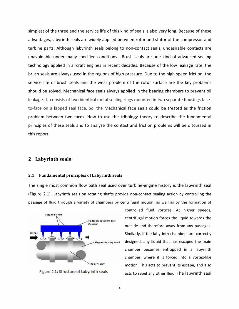
2.3 Su
Under st
not conta
research
believed
to disrup
turbulen
configura
land poi
turbulen
of surfac
FIGURE 2
problem cau
rfaceRoug
able operati
act each othe
of Stocker e
to be the re
pt the flow
ce might b
ation. The
nts out the
ce in reduci
e roughness
2.2: EFFECT OF
used by the
ghnessEffec
ing states, a
er, the surfac
t al. [1], the
esult of incre
field throu
e more tha
little change
e significant
ng leakage t
s on seal leak
F SURFACE ROU
thermal exp
ctontheLa
lthough the
ce roughness
e leakage re
eased frictio
ugh the sea
an offset by
e found in t
contributio
through mul
kage.
UGHNESS ON S
STRAIG
5
pansion but
abyrinthse
knife edges
also affects
eduction ach
on losses and
l. The bene
y the increa
he single kn
on of the bo
ti‐knife seal
SEAL LEAKAGE
HT SEAL (Ref. [
t also increa
eals
and abrada
the perform
hieved with
d higher sur
efit gained f
ased leakag
nife seal lea
oundary lay
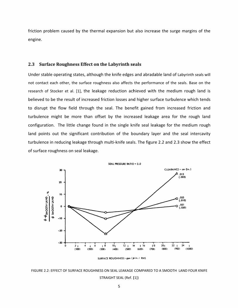
s. The figure
COMPARED TO
[1])
ase the surg
able land of L
ance of the s
h the mediu
rface turbule
from increa
ge area for
akage for th
yer and the
e 2.2 and 2.3
O A SMOOTH
e margins o
Labyrinth sea
seals. Base o
um rough la
ence which t
ased friction
the rough
e medium r
e seal interc
3 show the e
LAND FOUR K
of the
als will
on the
nd is
tends
n and
land
rough
cavity
effect
NIFE
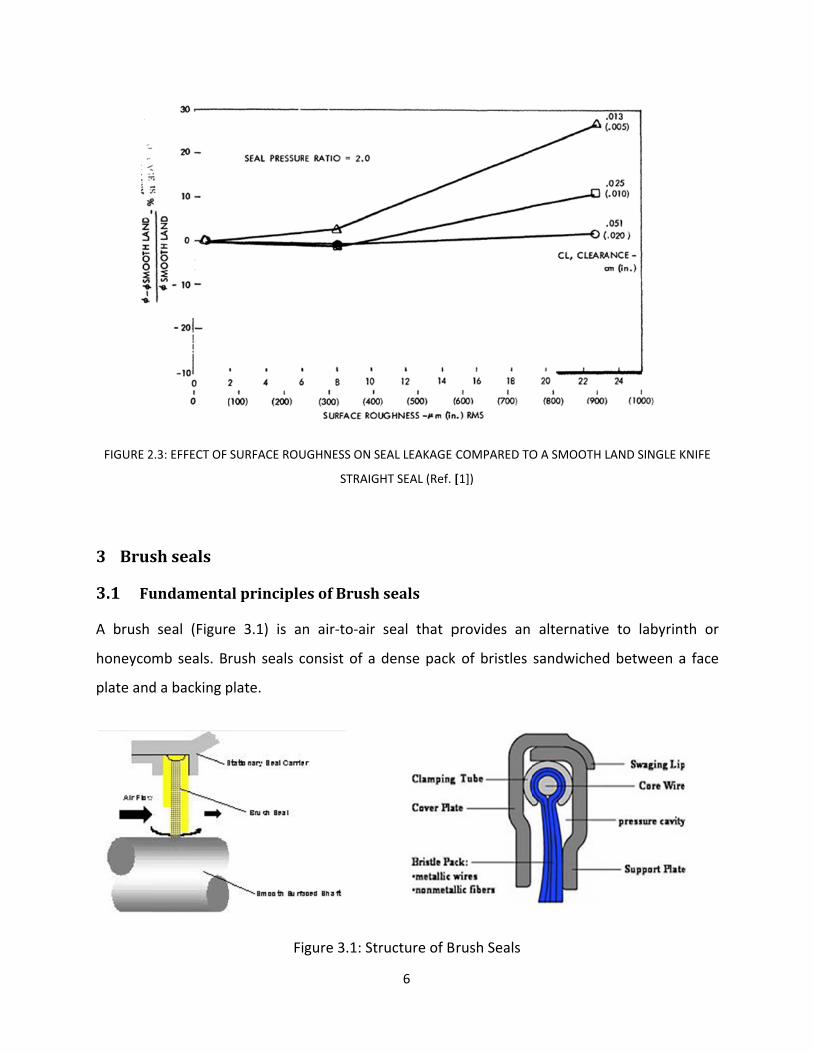
FIGURE 2
3 Brus
3.1Fu
A brush
honeyco
plate and
2.3: EFFECT OF
shseals
undamenta
seal (Figur
mb seals. B
d a backing p
SURFACE ROU
alprinciple
e 3.1) is an
rush seals c
plate.
Fi
UGHNESS ON S
STRAIG
esofBrush
n air‐to‐air
consist of a
gure 3.1: Str
6
EAL LEAKAGE C
HT SEAL (Ref. [
seals
seal that p
dense pack
ructure of Br
COMPARED TO
[1])
provides an
of bristles
rush Seals
O A SMOOTH L
alternative
sandwiched
LAND SINGLE K
e to labyrint
d between a
KNIFE
th or
a face
7
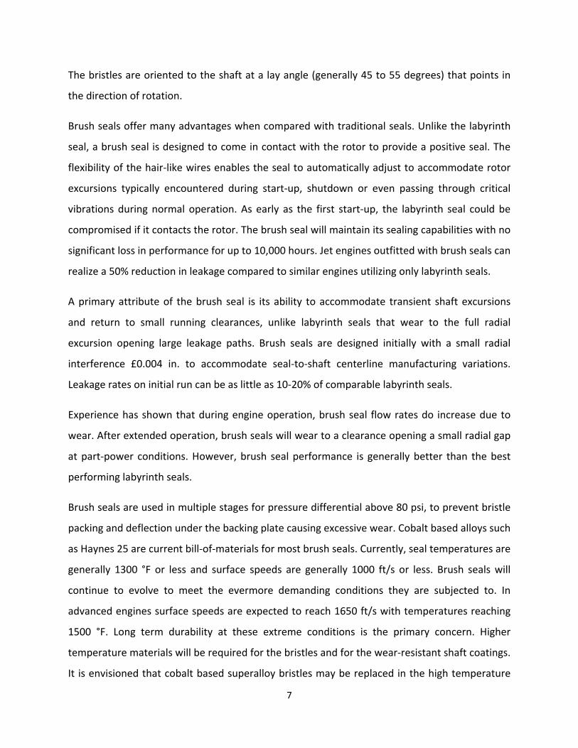
The bristles are oriented to the shaft at a lay angle (generally 45 to 55 degrees) that points in
the direction of rotation.
Brush seals offer many advantages when compared with traditional seals. Unlike the labyrinth
seal, a brush seal is designed to come in contact with the rotor to provide a positive seal. The
flexibility of the hair‐like wires enables the seal to automatically adjust to accommodate rotor
excursions typically encountered during start‐up, shutdown or even passing through critical
vibrations during normal operation. As early as the first start‐up, the labyrinth seal could be
compromised if it contacts the rotor. The brush seal will maintain its sealing capabilities with no
significant loss in performance for up to 10,000 hours. Jet engines outfitted with brush seals can
realize a 50% reduction in leakage compared to similar engines utilizing only labyrinth seals.
A primary attribute of the brush seal is its ability to accommodate transient shaft excursions
and return to small running clearances, unlike labyrinth seals that wear to the full radial
excursion opening large leakage paths. Brush seals are designed initially with a small radial
interference £0.004 in. to accommodate seal‐to‐shaft centerline manufacturing variations.
Leakage rates on initial run can be as little as 10‐20% of comparable labyrinth seals.
Experience has shown that during engine operation, brush seal flow rates do increase due to
wear. After extended operation, brush seals will wear to a clearance opening a small radial gap
at part‐power conditions. However, brush seal performance is generally better than the best
performing labyrinth seals.
Brush seals are used in multiple stages for pressure differential above 80 psi, to prevent bristle
packing and deflection under the backing plate causing excessive wear. Cobalt based alloys such
as Haynes 25 are current bill‐of‐materials for most brush seals. Currently, seal temperatures are
generally 1300 °F or less and surface speeds are generally 1000 ft/s or less. Brush seals will
continue to evolve to meet the evermore demanding conditions they are subjected to. In
advanced engines surface speeds are expected to reach 1650 ft/s with temperatures reaching
1500 °F. Long term durability at these extreme conditions is the primary concern. Higher
temperature materials will be required for the bristles and for the wear‐resistant shaft coatings.
It is envisioned that cobalt based superalloy bristles may be replaced in the high temperature

(up to 15
tenaciou
Under th
wear are
generate
investiga
not yet p
wear live
3.2So
Inherent
frictional
themselv
hysteresi
determin
500 °F) loca
s oxide, with
Fi
hese extrem
e highly des
ed during op
ated. Cerami
proven, hard
es.
olvethefric
flexibility o
l interaction
ves, brush se
is affects se
ning heat ge
ations. Nicke
h lower frict
igure 3.2: Br
e conditions
sirable. Rese
peration can
ic brush sea
d ceramic b
ctionprobl
of brush sea
n between t
eals are kno
eal perform
eneration a
el based sup
ion at highe
rush seals us
s, designs th
earchers are
aid in redu
als are being
ristles may
lemofBrus
als allows fi
the fibers a
own to exhib
ance after
nd seal wea
8
peralloys, su
r temperatu
sed in the PW
hat would sig
e investigati
cing wear. O
g investigate
be more we
shSealsby
bers to com
and the bac
bit pressure
a rotor exc
ar during h
uch as Hayne
ures.
W4000 aircra
gnificantly li
ng whether
Other propri
ed by a num
ear resistant
yfiniteelem
mpact under
cking plate a
stiffness an
ursion, pres
ard rubs. T
es 214, form
aft engine
imit the irre
r the small
ietary desig
mber of rese
t and may o
mentmetho
r pressure l
as well as w
d hysteresis
ssure stiffen
Typically bru
m a more st
ecoverable b
bristle lift f
ns are also b
earchers. Th
offer longer
od
oad. Due to
within the f
s behavior. W
ning is critic
ush‐rotor co
table,
bristle
orces
being
hough
term
o the
fibers
While
cal in
ontact
occurs at
extreme
stiffness
the effec
finite ele
3.2.1F
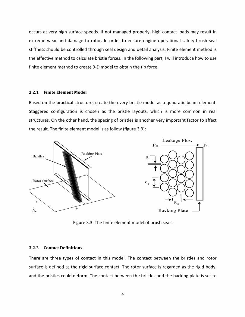
Based on
Staggere
structure
the resul
3.2.2C
There ar
surface i
and the b
t very high s
wear and d
should be c
ctive method
ment metho
FiniteEleme
n the practic
d configura
es. On the ot
t. The finite
ContactDefin
re three typ
s defined as
bristles coul
surface spee
damage to r
ontrolled th
d to calculate
od to create
ntModel
cal structure
ation is cho
ther hand, t
element mo
Figure 3.3
nitions
pes of conta
s the rigid su
d deform. T
eds. If not m
rotor. In ord
hrough seal d
e bristle forc
3‐D model t
e, create the
osen as the
the spacing o
odel is as fol
3: The finite
act in this m
urface conta
The contact
9
managed pro
der to ensur
design and d
ces. In the fo
to obtain the
e every brist
e bristle lay
of bristles is
low (figure 3
element mo
model. The c
act. The roto
between the
operly, high
re engine o
detail analys
ollowing par
e tip force.
tle model as
youts, which
s another ve
3.3):
odel of brush
contact betw
or surface is
e bristles an
contact loa
perational s
sis. Finite ele
rt, I will intro
s a quadratic
h is more c
ery importan
h seals
ween the b
s regarded a
nd the backi
ads may res
safety brush
ement meth
oduce how t
c beam elem
common in
nt factor to a
bristles and
as the rigid b
ng plate is s
ult in
h seal
hod is
o use
ment.
n real
affect
rotor
body,
set to

10
the softened contact, which is defined in the ABAQUS. And the slide line contact is used to
model the interaction among the bristles.
3.2.3FrictionDefinitions
The friction is defined as coulomb friction for all the contacts of the seal model. The friction
coefficient for Haynes 25 is 0.28 which is obtained by Crudgington et al [2].
3.2.4BoundaryConditions
The backing plate limits the axial motion of the bristles. Because the bristles are always stuck
together, we could assume the load just transfer between the first bristle and the last bristle
without considering the effect of the bristles between them. And rotor surface also should
have the velocity along the circumferential direction to simulate the actual operating status.
There exists an axial pressure drop with brush seals. The pressure distribution along the axial
direction is already given by Bayley et al. [3] and Braun et al. [4]. And the radial pressure
distribution is provided by Bayley et al. [3] and Turner et al. [5].
3.2.5Results
Based on the simulation result, the deformation of the cross‐section of the brush seals and
bristle tip force under different pressure are already given by Mahmut F, Aksit [6]. The result
will be shown in the picture 3.4 and 3.5. From the result, we could find out the magnitudes of
the bristle tip force are decided by the pressure load. Using this method, we could simulate the
operating status of the brush seal and obtain the contact pressure to predict the degree of
wear.

Figure 3.4
Figur
4: Modeled s
re 3.5: Conta
seal behavio
act force und
11
or under diffe
der different
erent pressu
t pressure lo
ure load (Ref
oad (Ref. [6]
f. [6]).
).
4 Mec
4.1 F
An end f
simply a
mechani
interface
The elem
maintain
4.1.1 B
Balance r
taken to
pressure
pressuriz
area ove
hanicalFa
undament
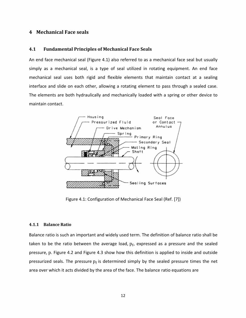
face mechan
s a mechan
cal seal use
e and slide o
ments are bo
n contact.
Fi
BalanceRati
ratio is such
be the rati
, p. Figure 4
zed seals. Th
r which it ac
aceseals
alPrinciple
nical seal (Fig
nical seal, is
es both rigi
on each oth
oth hydrauli
gure 4.1: Co
o
an importan
io between
4.2 and Figur
he pressure
cts divided b
esofMecha
gure 4.1) als
s a type of
id and flexi
er, allowing
cally and m
onfiguration
nt and wide
the average
re 4.3 show
p is determ
y the area o
12
anicalFace
so referred
seal utilize
ible elemen
g a rotating
echanically
of Mechanic
ly used term
e load,p , e
how this de
mined simpl
of the face. T
eSeals
to as a mec
ed in rotatin
nts that ma
element to
loaded with
cal Face Sea
m. The defini
expressed as
efinition is a
y by the se
The balance
chanical face
ng equipme
aintain cont
pass throug
h a spring or
l (Ref. [7])
ition of bala
s a pressure
applied to in
aled pressu
ratio equati
e seal but us
ent. An end
tact at a se
gh a sealed
r other devi
nce ratio sha
e and the se
nside and ou
re times the
ons are
sually
face
ealing
case.
ce to
all be
ealed
utside
e net

Fi
4.1.2 P
PV produ
relative
criterion
4.1.3 L
Seals ma
case, sea
fluid pre
small.
The mixe
operatio
gure 4.2: Ou
VParamete
uct is the pr
surface velo
used in the
ubricationR
y operate in
als develop a
ssure. In suc
ed friction is
n for many s
pπ r r
B B
pπ r r
B B
utside pressu
er
roduct of th
ocity betwe
design of se
Regimes
n any one of
a significant
ch cases, alm
s shown in
seals at least
r p π r
r p π r
urized seal
e nominal c
een the loa
eals is an exp
the three lu
t film thickn
most no tou
the second
t during part
13
r
outsidepr
r
insidepre
F
contact pres
ad‐bearing m
pression of t
ubrication re
ess such tha
uching occur
case. This i
t of their live
ressurizeds
essurizedse
Figure 4.3: In
ssure on a lo
material and
the limit of m
egimes descr
at the entire
rs, friction is
s probably t
es. Mixed fr
seal
eal
nside pressu
oad‐bearing
d its count
mild adhesiv
ribed in figur
e load is bei
s low, and w
the more co
iction is cha
urized seal
g surface and
erface. It is
e wear.
re 4.4. In the
ing supporte
wear will be
ommon mod
racterized b
(4.1)
(4.2)
(4.3)
(4.4)
d the
s the
e first
ed by
e very
de of
by the
14
fact that a part of the load is carried by actual mechanical contact even though most of the load
may be carried by fluid pressure. The small amount of mechanical contact that does occur may
be responsible for most of the total friction. Thus, in mixed friction the fraction of load
supported by mechanical contact becomes very important as to the level of friction developed
and consequently both friction heating and wear. The other important feature about the mixed
friction regime is that the film thickness is nearly as low as it can be because even a very small
decrease in nominal film thickness will radically increase the fraction of contact. Thus, leakage is
about as low as it can be in this regime.
The third part illustrates the boundary friction. Boundary lubrication is characterized by the
situation where either speeds are so low that fluid pressures have not developed or that the
quantity of lubricant present is so small that fluid pressures cannot develop. Even in this case
some small fraction of the load may be carried by fluid pressure if more than just a surface layer
of lubricant is present. However, the high friction developed by the mechanical contact will
cause high friction and high wear. While it is likely that boundary‐type lubrication may occur in
seals during some types of operation, ordinary high‐speed seals simply would not survive if
boundary lubrication only were operable. Friction heating and wear would be too high for most
materials to survive very long.
The likely situation occurring in many seals is that both mixed lubrication and full film
lubrication are occurring in different parts of the seal at the same time. Thus, some of the seal
may be in the mixed lubrication regime where leakage flow is small. Other parts may be
gapping open somewhat where leakage is high, but such regions may be act as a source of
liquid lubricant for the mixed lubrication part of the seal.
It can be simply stated that a mechanical face seal must have an adequate state of lubrication
relative to its environment and materials to operate successfully. An adequate state does not
mean that the condition of lubrication must be full film. Mixed lubrication with only a small
fraction of the load supported by contact will satisfy in most cases. What is absolutely essential,
however, is that this satisfactory state of lubrication not deteriorates for any reason into
predominantly boundary lubrication. If the satisfactory state of lubrication is lost, the seal will

wear ou
checking
film regim
4.1.4 L
Seal leak
paramete
may be c
mixed lu
order of
estimate
regions t
controlle
t excessivel
. If the state
me with the
eakage
kage is det
er is the film
calculated. I
brication re
magnitude
d using this
the seal gap
ed by the gap
y fast or be
e of lubricat
average film
Figur
ermined pr
m thickness.
If a seal has
gime. In this
of the com
s value. If a
p may be s
p in the seal
ecome dest
tion become
m thickness
re 4.4: Lubri
rimarily by
If the film th
s low leakag
s regime the
mbined mea
seal leaks
several time
, which in tu
15
troyed by so
es too good
being too la
cation Regim
the average
hickness ove
ge, most like
e effective v
an‐to‐peak r
excessively,
es the avera
urn is contro
ome therm
, such that
rge, then it
mes (Ref. [7]
e gap in th
er the entire
ely it is ope
value of the
roughness h
, them it is
age peak ro
olled by lubri
al mechanis
the seal op
may fail by l
])
he seal. The
e seal is know
erating pred
fluid film th
heights and
likely that
oughness he
ication.
sm such as
erates in th
leaking too m
e predomin
wn, then lea
ominately in
hickness is o
leakage ma
at least in s
eight. Leaka
heat
e full
much.
nating
akage
n the
of the
ay be
some
age is

4.2 S
4.2.1 Su
Figure 4.
on the la
carbon s
equal he
types of
roughnes
load bea
4.2.2 D
Height o
concepti
take a su
spaced p
be a pro
ordinate
heights.
ealingSurf
urfaceProfi
5 shows sur
apped carbo
urface is no
eight surrou
information
ss measures
ring curves.
Figu
Distribution
f a surface
on can be a
urface profil
points taken
obability de
density fun
faceDefinit
iles
rface profile
on. The profi
w more pro
nded by de
that can be
s, characteris
ure 4.5: Surfa
ofSurfaceH
is usually co
pplied. Rath
e of sufficie
from the pr
nsity functio
nction to di
tionandM
s obtained f
ile shows ho
operly charac
epressions a
e obtained fr
stic length m
ace Profile o
Heights
onsidered to
her than pic
nt length an
ofile as show
on of surfa
istinguish it
16
easuremen
for actual se
ow the aspe
cterized as c
nd valleys.
rom such pro
measures an
of a Worn Ca
o be a rando
king random
nd then mak
wn in Figure
ce height. T
from dens
nt
eal materials
erity tips hav
consisting of
There are m
ofiles. These
nd autocorre
arbon Surfac
om variable
m locations t
ke a histogra
4.6. The res
This functio
ity function
s. It shows th
ve been wor
f flat‐topped
many differe
e include he
elation, aspe
ce (Ref. [7]).
e. Figure 4.6
to measure
am of the h
sulting curve
on is referre
ns of peak h
he effect of
rn off. In fac
d regions of
ent features
ight distribu
erity tip radii
6 shows how
height, one
heights of eq
e is consider
ed to as th
heights or v
wear
ct the
f near
s and
utions,
i, and
w this
e may
qually
red to
e all‐
valley

There ar
surface h
on the cl
The seco
4.2.3 Su
There are
most com
Figure 4.6
re two very
heights or fro
ass. First, th
ond paramet
urfaceRoug
e many roug
mmon
6: A surface
important m
om the dens
e mean valu
∑
er is the sta
∑
ghness
ghness param
∑
profile and
measures th
sity function
ue is given by
ndard devia
∑
meters in us
∑ | |
17
its all‐ordina
hat can be d
n itself. Ther
y
tion
e. Arithmeti
|
ate density f
derived eith
re two param
ical mean ro
function (Re
her from hav
meters are a
oughness (Ra
f. [7])
ving a samp
already desc
a) is by far th
ple of
ribed
(4.5)
(4.6)
(4.7)
(4.8)
he
(4.9)

18
| | (4.10)
Root Mean Square or RMS Roughness is another averaging measurement
∑ (4.11)
(4.12)
4.2.4 NormalDistribution
The “normal distribution” is given by a particular density function, the Gaussian curve, which
has certain important mathematical features. It happens that data from many natural physical
phenomena fit the normal distribution curve. Many other mathematical curves can also be
used to fit such data equally well, but the normal distribution function is used because of its
early origins and because it provides certain mathematical conveniences. One should always
recognize that the normal distribution is the approximation of a physical phenomenon and
provides no deeper meaning. In fact the use of such an idealization may be quite misleading.
For example, the normal distribution, when fitted to a density function for a surface, predicts
the existence asperities of infinite height and valleys of infinite depth, clearly not physically true.
Density function shapes for real surfaces do vary considerably. In fact this variation from the
Gaussian curve is very useful in characterizing the surface. Yet, for many analyzes and
discussions, surfaces are considered to be “normal”. There are several reasons. The first is that
many surfaces can be well approximated by the normal distribution function. Second, it is often
more important to be able to use a mathematically convenient function for analysis and
discussion than it is to avoid the errors that might be introduced by making such an assumption.
Third, even though the entire surface may not be normal, it is likely that the interactive part of
the surface, which is the region at and just below the peaks, does behave as a normal function.
Finally, since most engineers are familiar with the normal distribution but not other
distributions, use of the normal distribution approximation simply makes discussing surfaces in

19
terms of their statistical properties easier to understand. Thus, this distribution is always
selected to be a approximation to the distribution of surface heights for seal surfaces.
4.3 TribologicalProperties
While many of the physical and mechanical properties do affect tribological behavior, there are
nevertheless some material‐specific tribological properties that one does not find included as
material properties. Three such properties of importance are friction coefficient, wear rate, and
the PV (pressure times velocity) limit. While some might debate that these are properties
because the values depend strongly on nonmaterial factors that are difficult to control or
undefined, there is nevertheless a strong relationship between the properties mentioned and
material type. Data for these properties is very useful.
Friction coefficient in seals is specific to the system consisting of the two face materials, their
precise geometry, the fluid, the speed, the pressure, and so forth. In fact, it is well known that
by designing different experiments for seals, one can measure a wide range of friction
coefficients. Thus, reported values of friction coefficients are specific to the exact conditions
under which the measurements were taken and have limited value in another context.
The second type of tribological data of interest is wear rate. This data may not repeat from seal
design to seal design because the condition of lubrication may be totally different. To use the
wear coefficient data, the wear coefficient K is defined as is described by Johnson and
Schoenherr (1980):
(4.13)
where the hardness H must be defined in the same units as pressure. Thus, for hardness values
expressed by a Brinell number or by the Vicker’s hardness number, which are both in (kg/mm2).
The wear coefficient K is consistent with adhesive wear theory (See Halling, 1978). Ideally, if

20
one knows the hardness H, the wear coefficient is used as K/H such that one obtains a wear
coefficient for a given material pair of given hardness.
The pressure times velocity limit, which is commonly known as the PV limit, can be considered
as a material property even though just like friction coefficient, it can be influenced by many
other factors of design. PV limit does have a very strong material dependence. The question
that arises in relation to the PV limit is what limit one is talking about. In some seal tests PV is
given its limiting value based on limiting wear rate to satisfactory levels.
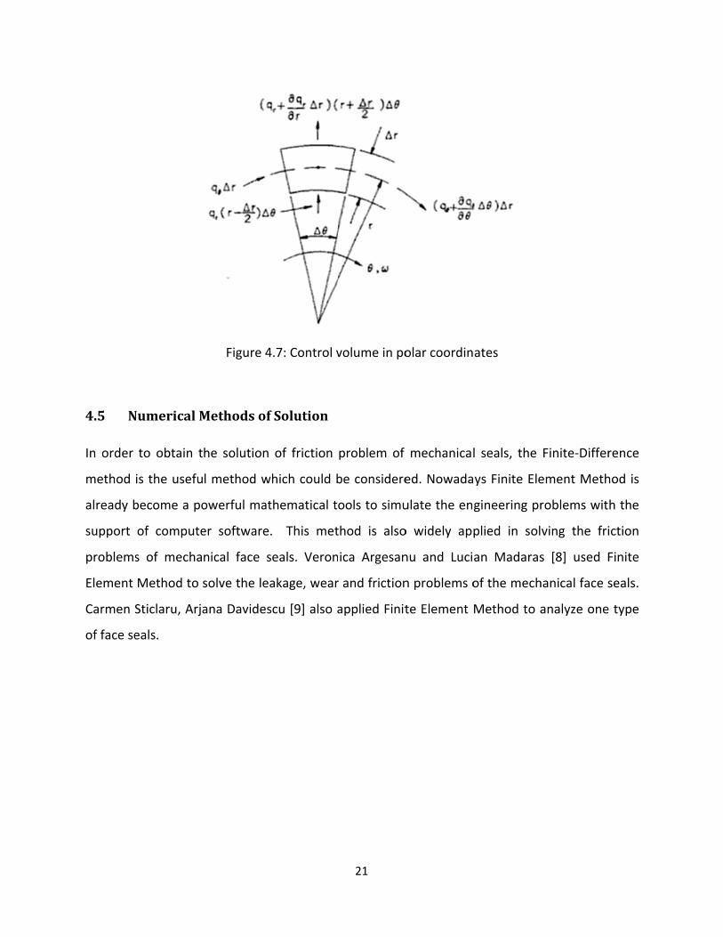
4.4 FluidPressureDistribution
In order to analyze the friction of the mechanical seals, the fluid pressure distribution is also
need to be considered. It is more convenient to use the Reynolds equation in its polar
coordinate form. With reference to the polar coordinate system shown in Figure 4.7, we could
obtain
(4.14)
(4.15)
With reference to Figure 4.7 the net sum of the volume rate of flow into the control volume can
be obtained by summing the flows shown. Thus, neglecting the squeeze film effects as before,
continuity requires that
0 (4.16)
Upon substitution of equations 4.14 and 4.15 into equation 4.16, the Reynolds equation in
polar coordinates is given by
(4.17)
4.5 N
In order
method
already b
support
problems
Element
Carmen S
of face se
NumericalM
to obtain t
is the usefu
become a po
of compute
s of mecha
Method to
Sticlaru, Arja
eals.
Figure 4
Methodsof
he solution
l method w
owerful mat
er software.
nical face s
solve the lea
ana Davides
4.7: Control v
fSolution
of friction
which could b
thematical t
. This met
seals. Veron
akage, wear
scu [9] also a
21
volume in po
problem of
be considere
ools to simu
thod is also
ica Argesan
r and friction
applied Finit
olar coordin
mechanical
ed. Nowada
ulate the en
o widely app
nu and Luci
n problems o
te Element
ates
l seals, the
ys Finite Ele
gineering pr
plied in sol
an Madaras
of the mech
Method to a
Finite‐Differ
ement Meth
roblems wit
ving the fri
s [8] used F
hanical face s
analyze one
rence
hod is
h the
iction
Finite
seals.
type

22
5 Conclusion
From the above description and analysis, it is obvious that the three kinds of seals which are
widely applied in modern aircraft engines have the close relation with the tribology theory,
although there are great differences among the principles and the structures of three kinds of
seals. Labyrinth seals are a kind of non‐contact seals. During the stable operating status, the
surface roughness also has the impact on the performance of the seals. When the working
status of Labyrinth seals becomes stable, several powerful methods are used to deal with
friction problems causing by the undesirable contact. For brush seals, contact forces between
the tip of bristles and rotor surface is the very important factor to affect the performance and
the friction ratio of the brush seals. The friction problems of the interface also need to be
solved with the help of the tribology theory. The mechanical face seals could be treated as the
friction problem between two faces, and a lot of existing tribology models and theories could
be applied to solve this problem. From these cases, we could find out the importance of the
tribology theory during the design process of seals. With the development of the research and
the improvement of the calculate method, more detailed and more deep problem will be
considered, and it will have an important meaning to promoting the efficiency and extending
the service life of the modern aircraft engine.

23
Bibliography
[1] H. L. Stocker, D. M. Cox, G. F. Holle. Aerodynamic Performance of Conventional and
Advanced Design Labyrinth Seals with Solid‐smooth, Abradable, and Honeycomb Lands.
National Aeronautics and Space Administration, NAS 2‐20056, 1977.
[2] Crugington, P. F, and Bowsher, A, Brush Seal Pack Hysteresis, 2002, AIAA Paper No. AIAA‐
2002‐3794.
[3] Bayley, F.J., and Long, C.A., A Combined Experimental and Theoretical Study of Flow and
Pressure Distributions in a Brush Seal, ASME J. Eng. Gas Turbines Power, 115, No.2 (1993) 404‐
410.
[4] Braun, M. J., Hendricks, R. C., and Canacci, V., Flow Visualization in a Simulated Brush Seals,
ASME Paper No. 90‐GT‐217, 1990.
[5] Turner M. T., Chew, J. W., and Long, C.A., Experimental Investigation and Mathematical
Modeling of Clearance Brush Seals, ASME J. Eng. Gas Turbines Power, 120, No.3, 1998, 573‐579.
[6] Mahmut F. Aksit*. 3‐D Analysis of High Density Brush Stiffness with Friction‐Pressure
Coupling, Sabanci University, Istanbul, Turkey, 34956.
[7] Alan O. Lebeck, Principles and Design of Mechanical Face Seals, 1991 byJohn Wiley & Sons,
Inc.
[8] Veronica Argesanu, Lucian Madaras, Leakage, Wear and Friction in the Mechanical Face
Seals Analyzed by FEM, The Annals of University, FASCICLE VIII, Tribology, 2003 ISSN 1221‐4590.
[9] Carmen Sticlaru, Arjana Davidescu, Studies by Finite Element Method Applied on Face Seal,
Mechanical Engineering Vol. 2, No 1, 2004, pp. 59‐68.