Embed Size (px)
Citation preview

Power Factor Correction
APPLICATION OF POWER FACTORCORRECTION CAPACITORS
Understanding Power Factor
As with any equipment, an electrical system handles its job to some degree of efficiency ranging from poor to excellent. The measure of electrical efficiency is known as Power Factor.
The motors and other inductive equipment in a plant require two kinds of electric power. One type is working power, measured by the kilowatt (kW). This is what actually powers the equipment and performs useful work. Secondly, inductive equipment needs magnetizing power to produce the flux necessary for the operation of inductive devices. The unit of measurement of magnetizing or reactive power is the kilovar (kVAR). The working power (kW) and reactive power (kVAR) together make up apparent power which is measured in kilovoltamperes(kVA).
Most AC power systems require both kW (kilowatts) and kVAR (kilovars).Capacitors installed near the loads in a plant are the most economical and efficient way of supplying these kilovars. Low voltage capacitors are traditionally a high reliability maintenance-free device.
On the spot delivery of magnetizing current provided by capacitors means that kilovars do not have to be sent all the way from the utility generator to you. This relieves both you and your utility of the cost of carrying this extra kilovar load. The utility charges you for this reactive power in the form of a direct, or indirect power factor penalty charge. In addition, you'll gain system capacity, improve voltage and reduce your power losses.
How Capacitors Work
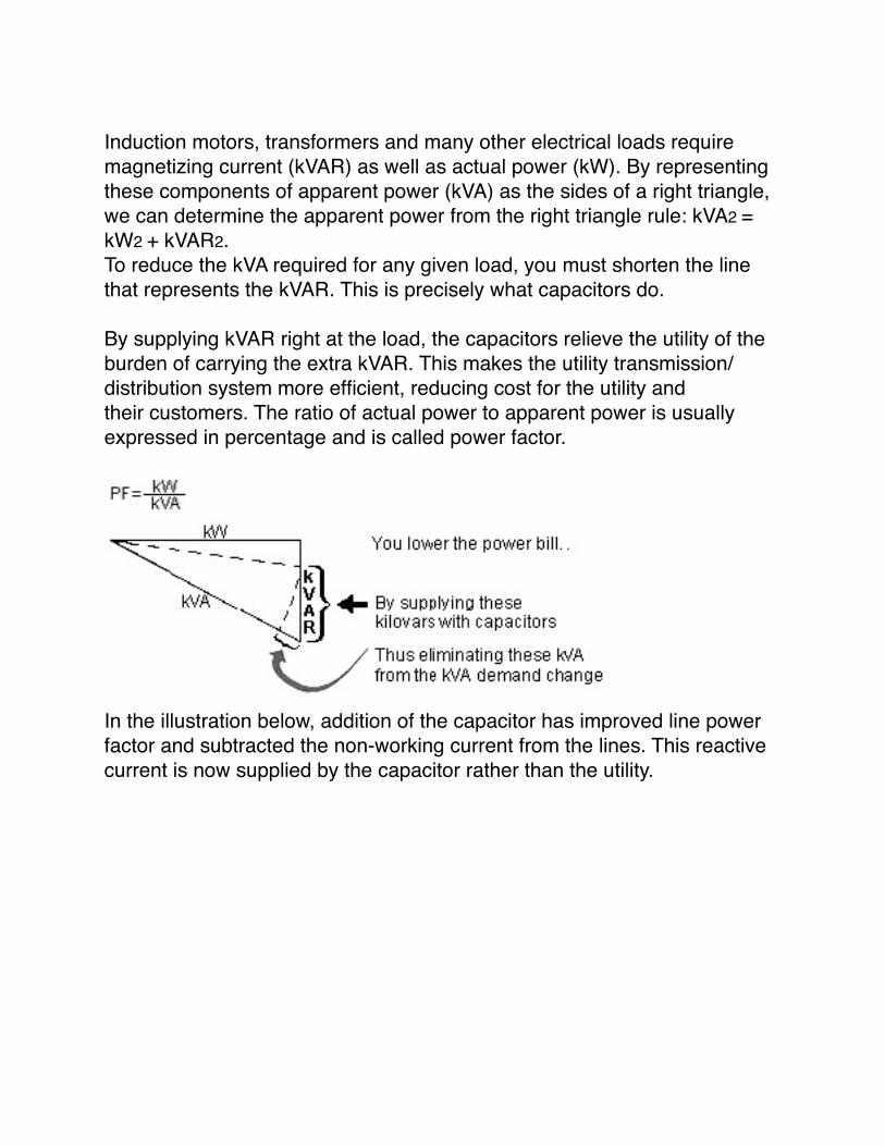
Induction motors, transformers and many other electrical loads requiremagnetizing current (kVAR) as well as actual power (kW). By representing these components of apparent power (kVA) as the sides of a right triangle, we can determine the apparent power from the right triangle rule: kVA2 = kW2 + kVAR2.To reduce the kVA required for any given load, you must shorten the line that represents the kVAR. This is precisely what capacitors do.
By supplying kVAR right at the load, the capacitors relieve the utility of theburden of carrying the extra kVAR. This makes the utility transmission/distribution system more efficient, reducing cost for the utility andtheir customers. The ratio of actual power to apparent power is usually expressed in percentage and is called power factor.
In the illustration below, addition of the capacitor has improved line power factor and subtracted the non-working current from the lines. This reactive current is now supplied by the capacitor rather than the utility.
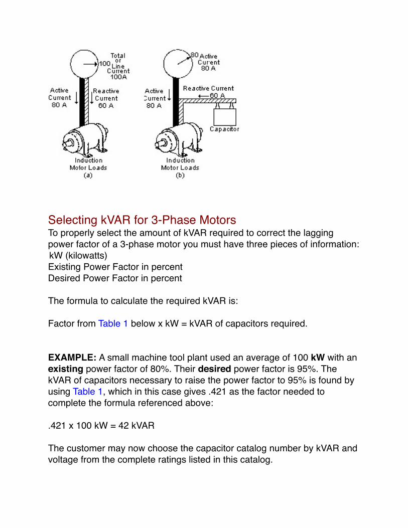
Selecting kVAR for 3-Phase MotorsTo properly select the amount of kVAR required to correct the lagging power factor of a 3-phase motor you must have three pieces of information: kW (kilowatts)Existing Power Factor in percentDesired Power Factor in percent
The formula to calculate the required kVAR is:
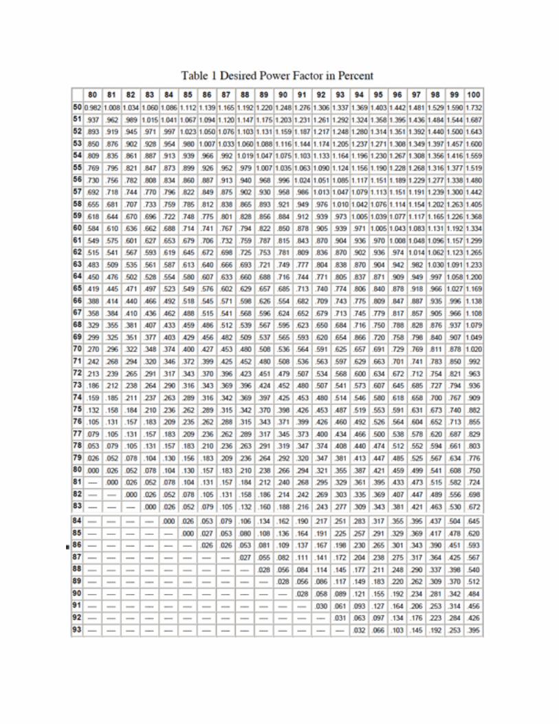
Factor from Table 1 below x kW = kVAR of capacitors required.
EXAMPLE: A small machine tool plant used an average of 100 kW with anexisting power factor of 80%. Their desired power factor is 95%. The kVAR of capacitors necessary to raise the power factor to 95% is found by using Table 1, which in this case gives .421 as the factor needed to complete the formula referenced above:
.421 x 100 kW = 42 kVAR
The customer may now choose the capacitor catalog number by kVAR andvoltage from the complete ratings listed in this catalog.

If kW or Present Power Factor are not known you can calculate from thefollowing formulas to get the three basic pieces of information required tocalculate kVAR:
WHEREI = full load current in ampsE = voltage of motorPF = Present power factor as a decimal (80% = .80)HP = rated horsepower of motoreff = rated efficiency of motor as a decimal (83% = .83)
If Desired Power Factor is not provided, 95% is a good economical power factor for calculation purposes.
Benefits of Power Factor Correction CapacitorsThe application of shunt capacitors to industrial power systems has several benefits. Among these are:
Benefit 1 - Reduce Power BillsIn areas where a kVA demand clause or some other form of low power factor penalty is incorporated in the electric utility's power rate structure, capacitors reduce power bills by reducing the kVA or kVAR demand.
EXAMPLE: kVAR Demand ChargeA plant with a demand of 1800 kVA, 1350 kW and 1200 kVAR has a contract for power factor which includes an energy charge for kWH, a demand charge based on kW, and another demand charge based on kVAR. The kVAR demand can be eliminated by the addition of capacitors.

In our example, the kVAR charge is $1.50 per month for each kVAR of demand in excess of 1/3 of the kW demand.
Step 1 ) Calculate kVAR demand in excess of 1/3 of the kW demand.
(capacitors can supply this kVAR)
Step 2) Estimated annual power bill savings.$1.50 demand charge x 750 kVAR x12 months = $13,500 savings
Step 3) Estimate the cost of 750 kVAR of capacitors. (On a 480 volt systeminstalled capacitor cost is approximately $15/kVAR)750 kVAR x $15 = $11,250 capacitor cost
$13,500 annual savings vs. $11,250 capacitor investment. Capacitors will pay for themselves in 10 months, and continue to produce savings thereafter.
EXAMPLE: kW Demand ChargeA plant with a demand of 1000 kW has an 80% power factor. The serving utility has a target power factor of 85'%o and a kW demand charge. This example will show how the power factor of the plant load helps determine the kW billing charge. Therefore, the kW billing can be reduced by improving the plant power factor to the targeted 85%.
The utility in our example has a kW demand charge of $9.00 and a target power factor of 85%. The monthly kW billing is determined by the ratio of target power factor to the existing power factor times kW demand.
Step 1) Calculate amount of monthly kW billing. (as specified by Utility)
$9.00 kW demand charge x 1062 kW = $9,558 billing.

Step 2) Now determine the amount of kVAR required to improve the power factor to 85%. Simply multiply the kW by the factor obtained from Table 1. The factor to calculate from .80 to .85 power factor is .130.
.130 x l000 kW = 130 kVAR (required kVAR to meet 85% target pf).
Step 3) Estimate the cost of 130 kVAR of capacitors. (On a 480 volt system, installed capacitor cost is approximately $15/kVAR)
130 kVAR x $15 = $1,950 (capacitor investment)
Step 4) Calculate amount of kW billing with new power factor.
$9.00 kW demand charge x 1000 kW = $9,000 billing.
Step 5) Compare both kW billing charges.80% pf kW billing $9,55885% pf kW billing $9,000$ 558 Savings
A monthly power bill savings of $558 with a 3 1/2 month payback on thecapacitor investment and continued savings thereafter.
EXAMPLE: kVA Demand ChargeAnother plant with 400 kW and 520 kVA demand has a power contract which calls for a demand charge based on kVA. This kVA demand can be reduced if the power factor is raised.
The demand charge in our example is $3.00 per kVA per month. The amount of capacitor kVAR to be added can be determined by checking the savings which can be realized after power factor improvement. Often 95% is a good economical power factor.

Step 1) The Present Power Factor =
(a low power factor)
Step 2) Let's assume that we install enough capacitors to raise the power factor to 95%. This would reduce the present 520 kVA demand down to 421 kVA.Calculated as follows:
Step 3) Since the local power rate includes a monthly $3.00/kVA demand charge, you would calculate the savings in demand charge as follows:
Present kVA—Reduced kVA = kVA SavedkVA Saved x kVA Demand Charge = $ Savings
or
520 - 421 = 99
99 x $3.00 = $297.00 savings per month
If annualized, the savings would be $3564 per year.
Step 4) Now calculate the kVAR size of capacitors required to accomplish the 95% desired power factor. By referring to Table 1, we find that the multiplier to go from 77% to 95% is 0.500. Thus:kW x Factor from Table 1 = kVARor400 x .500 = 200 kVAR
Step 5) Assuming $ 15 a kVAR as a complete installed cost of 480-volt system capacitors, the 200 kVAR would cost about $3000. Therefore, the 200 kVAR will pay for themselves in 10 months, and keep right on saving.
Benefit 2 - Gains in System CapacityIn thermally-limited equipment, such as transformers or cable, capacitors release capacity and thus allow a greater payload. By furnishing the necessary magnetizing current for induction motors and transformers, capacitors reduce the current drawn from the power supply. Less current means less load on transformers and feeder circuits. If a system has an existing overload, the capacitors may eliminate it. If the system is not overloaded, capacitors can release capacity and postpone or avoid an investment in more expensive transformers, switchgear and cable, otherwise required to serve additional loads.
EXAMPLE:There are four steps to follow to calculate the gain in system capacity:
1 ) Determine how much load increase is required.Let's assume that 20% more load is expected in the plant.
2) From monthly power bills, determine the present kW demand and powerfactor.As shown in Benefit 1, the monthly power bill shows a 400 kW demand, 520 kVA demand and a power factor of 77% (power factor = kW demand divided by kVA demand).
3) Determine how high the power factor must be raised to gain the capacity required.In our example, we want 20% additional capacity. The vertical axis on the graph below represents released system capacity percentages. Follow the horizontal line for 20% to the right until you reach the original power factor of .77. Then follow down to the corrected power factor line which shows approximately 95%. This is the new power factor required to gain the targeted increase in system capacity.
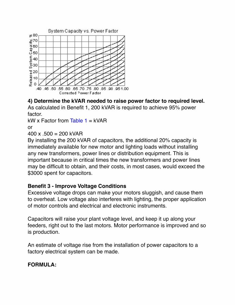
4) Determine the kVAR needed to raise power factor to required level.As calculated in Benefit 1, 200 kVAR is required to achieve 95% power factor.kW x Factor from Table 1 = kVARor400 x .500 = 200 kVARBy installing the 200 kVAR of capacitors, the additional 20% capacity isimmediately available for new motor and lighting loads without installing any new transformers, power lines or distribution equipment. This is important because in critical times the new transformers and power lines may be difficult to obtain, and their costs, in most cases, would exceed the $3000 spent for capacitors.
Benefit 3 - Improve Voltage ConditionsExcessive voltage drops can make your motors sluggish, and cause them to overheat. Low voltage also interferes with lighting, the proper application of motor controls and electrical and electronic instruments.
Capacitors will raise your plant voltage level, and keep it up along your feeders, right out to the last motors. Motor performance is improved and so is production.
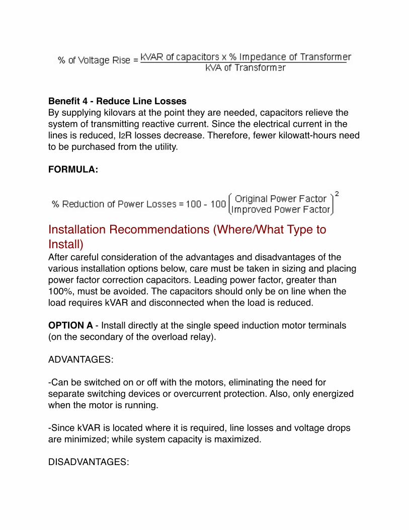
An estimate of voltage rise from the installation of power capacitors to a factory electrical system can be made.
FORMULA:
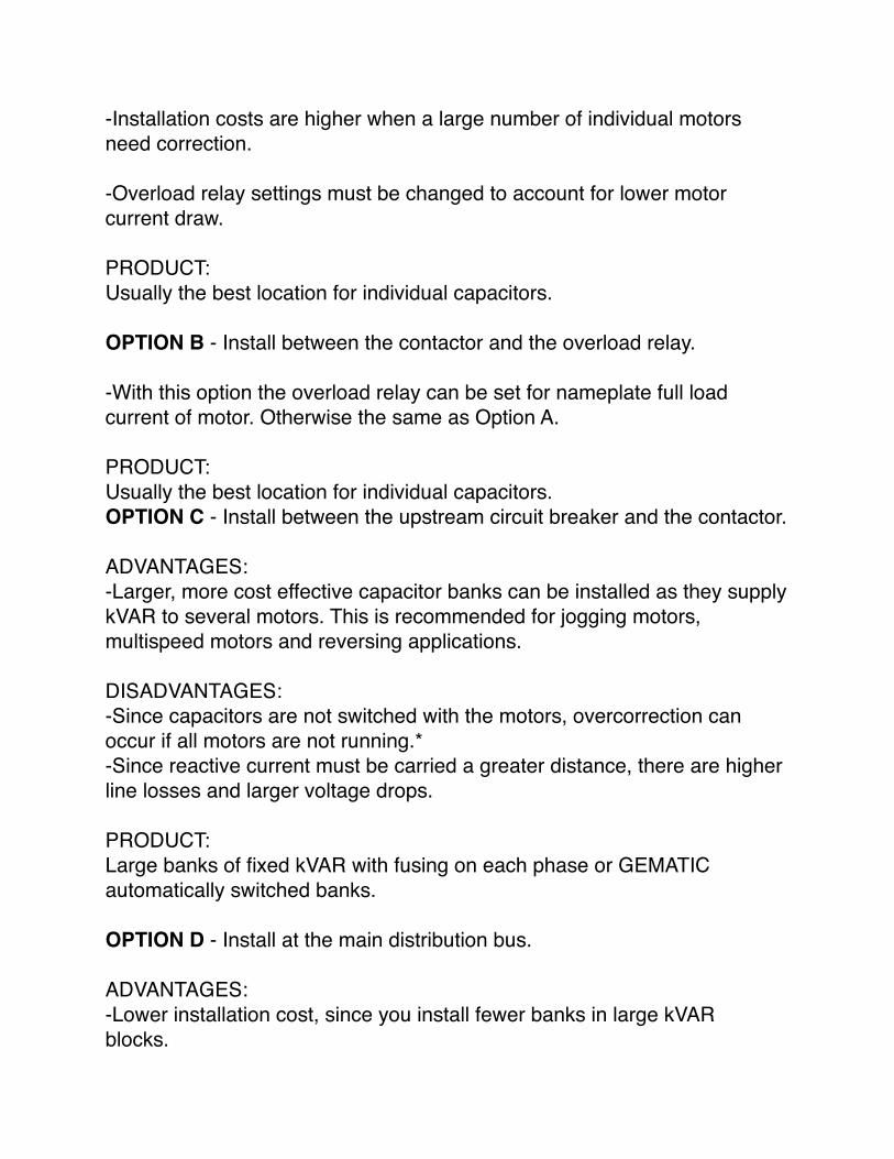
Benefit 4 - Reduce Line LossesBy supplying kilovars at the point they are needed, capacitors relieve the system of transmitting reactive current. Since the electrical current in the lines is reduced, I2R losses decrease. Therefore, fewer kilowatt-hours need to be purchased from the utility.
FORMULA:
Installation Recommendations (Where/What Type to Install)After careful consideration of the advantages and disadvantages of the various installation options below, care must be taken in sizing and placing power factor correction capacitors. Leading power factor, greater than 100%, must be avoided. The capacitors should only be on line when the load requires kVAR and disconnected when the load is reduced.
OPTION A - Install directly at the single speed induction motor terminals (on the secondary of the overload relay).
ADVANTAGES:
-Can be switched on or off with the motors, eliminating the need forseparate switching devices or overcurrent protection. Also, only energizedwhen the motor is running.
-Since kVAR is located where it is required, line losses and voltage dropsare minimized; while system capacity is maximized.
DISADVANTAGES:
-Installation costs are higher when a large number of individual motors need correction.
-Overload relay settings must be changed to account for lower motor current draw.
PRODUCT:Usually the best location for individual capacitors.
OPTION B - Install between the contactor and the overload relay.
-With this option the overload relay can be set for nameplate full loadcurrent of motor. Otherwise the same as Option A.
PRODUCT:Usually the best location for individual capacitors.OPTION C - Install between the upstream circuit breaker and the contactor.
ADVANTAGES:-Larger, more cost effective capacitor banks can be installed as they supplykVAR to several motors. This is recommended for jogging motors, multispeed motors and reversing applications.
DISADVANTAGES:-Since capacitors are not switched with the motors, overcorrection can occur if all motors are not running.*-Since reactive current must be carried a greater distance, there are higherline losses and larger voltage drops.
PRODUCT:Large banks of fixed kVAR with fusing on each phase or GEMATICautomatically switched banks.
OPTION D - Install at the main distribution bus.
ADVANTAGES:-Lower installation cost, since you install fewer banks in large kVARblocks.
DISADVANTAGES:-Overcorrection can occur under lightly loaded conditions. *-A separate disconnect switch and overcurrent protection is required.
PRODUCT:Large banks of fixed kVAR with fusing on each phase or GEMATICautomatically switched banks.
*This condition can be compensated for by using GEMATIC automaticallyswitched banks.
Special Applications
Power Factor Correction Capacitors on Reduced Voltage Motors and Multi-Speed MotorsThe following shows capacitor connections for typical starting circuits for reduced voltage and multi-speed motors. Variations to these circuits do exist. Make sure that your circuit exactly matches the circuit shown here before applying capacitors. Failure to do so may result in damage to the motor. The main contacts, illustrated in the diagrams below as M1, M2, M3, reference the contacts that must be closed to start or run the motor. Capacitors should be connected on the motor side of the main contacts.

Consider Harmonics When Applying CapacitorsSystem harmonics should be considered when applying power factor correction capacitors. Although capacitors do not generate harmonics, under certain conditions they can amplify existing harmonics. Harmonics are generated when non-linear loads are applied to power systems. These non-linear loads include: adjustable speed drives, programmable

controllers, induction furnaces, computers, and uninterruptible power supplies. Capacitors can be used successfully with nonlinearloads when harmonic resonant conditions are avoided.
To minimize the occurrence of harmonic resonance, the resonant harmonic of the system including the capacitor should be estimated. The resonant frequency can be calculated by:
whereh = calculated system harmonickVAsc = short circuit power of the systemkVAR = rating of the capacitorHarmonic values of 5, 7, 11, and 1 3 should be avoided as they correspond to the characteristic harmonics of non-linear loads. The harmonic value of 3 should also be avoided as it coincides with harmonics produced during transformer energization and/or operation of the transformer above rated voltage.Once identified the resonant harmonics can be avoided in several ways.
1. Change the applied kVAR to avoid unwanted harmonics.
Although this is the least expensive way to avoid resonant harmonics, it isnot always successful because typically some portion of the applied kVARis switched on and off as load conditions require. The calculation of systemharmonics should be repeated for each level of compensation. Adjustingthe size of the capacitor(s) may be necessary to avoid the harmonic values.
2. Add harmonic filters.
In order to filter harmonics at a specific site, tuned harmonic filters can beapplied. A capacitor is connected in series with an inductor such that theresonant frequency of the filter equals the harmonic to be eliminated.Tuned filters should never be applied without a detailed analysis of thesystem. The currents expected to flow in the filter are difficult to predict
and are a complex function of the system and load characteristics.
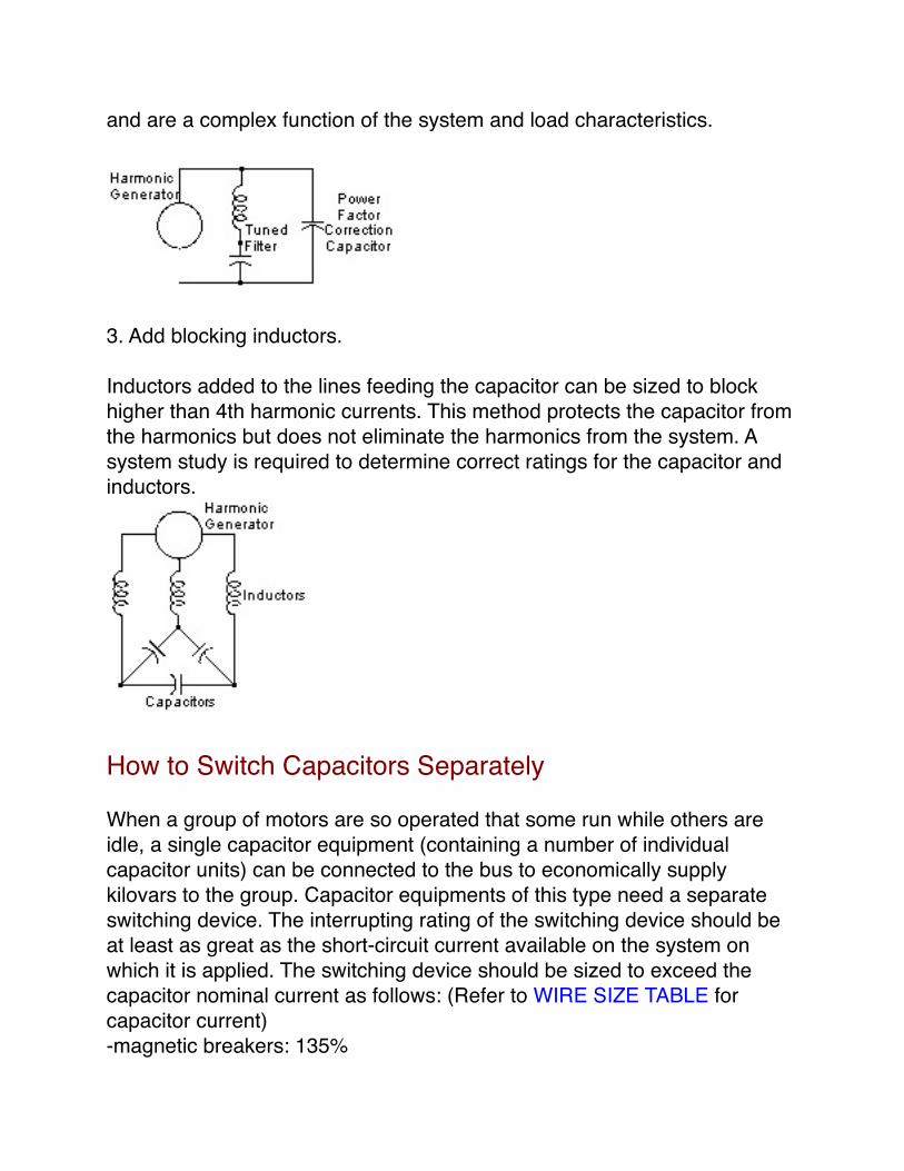
3. Add blocking inductors.
Inductors added to the lines feeding the capacitor can be sized to blockhigher than 4th harmonic currents. This method protects the capacitor fromthe harmonics but does not eliminate the harmonics from the system. Asystem study is required to determine correct ratings for the capacitor andinductors.
How to Switch Capacitors Separately
When a group of motors are so operated that some run while others are idle, a single capacitor equipment (containing a number of individual capacitor units) can be connected to the bus to economically supply kilovars to the group. Capacitor equipments of this type need a separate switching device. The interrupting rating of the switching device should be at least as great as the short-circuit current available on the system on which it is applied. The switching device should be sized to exceed the capacitor nominal current as follows: (Refer to WIRE SIZE TABLE for capacitor current) -magnetic breakers: 135%

-fusible switches: 165%-molded case breakers: 150%
For small capacitors, a separate wall-mounted switch or air circuit breaker of the enclosed type can be used. For large capacitors, the breaker or switch can be housed with the capacitors. When connected through metal-clad switchgear, capacitors should be treated as any other load and the breaker added to the existing switchgear.
If a large number of switching operations is expected, a solenoid-operatedcontactor may be used in place of a circuit breaker. The contactor offers a much longer expected life when switching normal load current. However, it does not provide short-circuit protection, so fuses must be added for this purpose where contactors are used.
Table 1 Desired Power Factor in Percent