Embed Size (px)
Citation preview

ICSBE2016-262
The 7th International Conference on Sustainable Built Environment, Earl’s Regency Hotel, Kandy, Sri Lanka from 16th to 18th December 2016
APPLICATION OF POST TENSIONS IN HIGH RISE BUILDING CONSTRUCTION IN SRI LANKA
S.H.M.A.P.K De Silva1*, Sudhira De Silva2 and P.B.R. Disanayake3
1Charted Structural Engineer, Colombo, Sri Lanka2Senior Lecturer, Faculty of Engineering, University of Ruhuna, Galle, Sri Lanka
3Professor, University of Peradeniya, Kandy, Sri Lanka*E-Mail: shm.anuradha @ gmail.com, TP: +94772932745
Abstract: The world is changing; the economy is changing; and Architectural practice is changing. Therefore, there is a definite trend towards the irregular shapes with large spans in buildings due to the fact that there is now more emphasis on providing largeuninterrupted floor space which can result in higher rental returns. Today the building industry is taking the next step in concrete technologies by introducing post-tensionsystems to slab construction with the use of system formwork and high strength concrete. Post-tensioned concrete has proven to be a preferred method of construction for commercial and office buildings, residential apartments, high-rise condominiums, parking structures, and mixed-use facilities such as hotels and entertainments. The main benefits over conventionally reinforced concrete being its ability to span greater distances without resorting to thick slabs and beams (and the consequent loss of head height), reduce deflection and cracking, Reduction in overall building mass, which is important in zones of high seismicity and superior performance of diaphragm action at building irregularities. There are also some associated labour and time savings. The objective of this paper is to introduce the post tension slab system to Sri Lankan construction industry. This study willdiscuss the benefits of having post tension in building industry, challengers encounter in PT designs and quality controlling process during construction.
Keywords: high rise; parking structures; span; deflection and cracking; building mass;seismicity; diaphragm action; PT slabs;
1. Introduction
Over the last 20 years, many buildings with post-tensioned floor slabs have been successfully constructed in the USA, Middle East, South East Asia, with corresponding increases in both steelwork prices and delivery times due to rapid growth in global economy. However, with the rapid growth of industry, the demands for labour force and constructions time play a major role at cost of construction. As a result of economic growth in Sri Lanka, above factors generate significant interest in post tensioned floor constructions. Pre tension and Post tensioning Systems have been available in Sri Lanka since 1960s but, it was limited to pre-cast, pre tensioned / post tension beams and slab elements in bridge and slab constructions.
Post-tensioned floors are totally of cast in-situ concrete. They can be designed as two-
way or one way spanning flat slabs, one-way spanning ribbed slabs, waffle or as banded beam & slabs. There are a number of publications that highlight the suitability of in-situ reinforced concrete frames for both economy and speed of construction in high-rise buildings. Post-tensioned concrete will not always be the most suitable, but it should be properly evaluated while considering other most familiar techniques.
a soleHowever, Engineers haveresponsibility to overview all available construction methods to their clients.
The benefits of the post tension slab systems could be categorized as follows.
Rapid construction with minimal labour
requirement
Minimum storey heights by satisfying
Construction, servicing and operational
requirements
Architectural Flexibility

ICSBE2016-262
The 7th International Conference on Sustainable Built Environment, Earl’s Regency Hotel, Kandy, Sri Lanka from 16th to 18th December 2016
Design and Performance
Joint and crack-free construction
Optimum clear spans with Controlled
deflections.
Post tension flat slab floor systems, maximizes the ceiling zone available for horizontal services, minimizes the self-weight and foundation loads, and keeps down the overall height of the building. Thus, minimum story height is achieved. As a result, the story height of a building with post tension slab system can be less than that of a steel-framed or conventional RC building by as much as 300 mm per floor. This can give an extra story in a ten-story building. Alternatively, it minimizes the exterior surface area to be enclosed, as well as the vertical runs of mechanical and electrical systems. The reduced building volume will save on cladding costs and may reduce running costs of HVAC systems. Further to this, Rapid construction is readily achieved in multi-story buildings as pre-stressing leads to less congested slab construction (having minimal labour requirement) and early stressing enables forms to be stripped quickly and moved to the next floor. Introduction of system formwork (table forms or equivalent) will further speed the construction cycle.
Structural flexibility of the design and detailing can cope with irregular grids leaving more freedom to architectural designs, and services as tendons (with the use of corrugated flat ducts, Figure 09) can easily be deflected horizontally to suit the building’s geometry or curves at the openings.
In PT design, the depth of flat slab is usually controlled by deflection requirements, by the punching shear capacity around the column or by the tensile stress on top and bottom surface of the floor slab. Further, Post-tensioning improves control of deflections (by volume balance due to tendon profile) and enhances shear capacity mainly due to pre compression (P/A) and vertical component of pre stressing force by curvature of the tendons. Future flexibility is provided as knockout zones can be
identified for future service penetrations. Further, Appropriate details may also be incorporated to reduce the effects of restraint, which may otherwise lead to cracking (Figure 05-07). Crack-free construction is often exploited in car parks, water tanks etc. where, concrete surfaces exposed to an aggressive environment.
Having considered all above aspects Post tension floor slab construction will produce cost effective solutions to Sri Lankan construction industry. The objective of this publication is to introduce the post tension slab systems to Sri Lankan construction industry. This study will discuss the benefits to both the developers and designer of having post tension in building industry, challenges encountered in PT designs and quality controlling process during construction.
2. Challenges of post-tensioning in Sri Lankan construction industry
For most multi-story buildings there are several suitable concrete floor framing systems, e.g. conventional RC floors, steel composite floor systems, post tension floors and precast pre tension floor systems. For spans greater than 6.0 m or where building floor arrangement is highly irregular, post-tension slabs start to become cost-effective. It can be used alone or combined with reinforced concrete to provide a competitive cost effective solution to a variety of available in-situ concrete floor systems.
In the past, Sri Lankan construction industry basically followed the conventional RC systems with conventional formwork systems for any type of building construction except in few projects where pre cast pre tension floor beams; steel composite floor systems and system formwork were used. Pre cast pre tension systems were highly promoted during the period of 1960-2000 with the pioneering efforts of Dr A. N. S Kulasinghe [16-17]. Though it was cheaper, it was not practical for high-rise building where complicated loading behaviours to be considered and also due to construction difficulties (storage and handling). Even though concept of post

ICSBE2016-262
The 7th International Conference on Sustainable Built Environment, Earl’s Regency Hotel, Kandy, Sri Lanka from 16th to 18th December 2016
tension is almost similar with the pre tension, it took decades to introduce post tension systems to Sri Lanka due to unavailability of specialized sub-contractors, confusions with pre tension systems, myths about post tension, unavailability of cost comparisons and lack of exposure to international cods such as ACI318[1,2], Technical report 43[3] etc.
As most of the clients, contractor’s wants to know the cost saving rather than time saving. Cost comparison was done considering height gain, concrete, formwork, reinforcement, architectural finishes (ceiling, painting and facade etc.) and additional revenue. Following case studies will show the cost benefits to the client.
Case Study 1
As a first step of major expectations, author got a rare chance to introduce the post tension floor systems to the Sri Lankan construction industry through Platinum tower project where there were lots of constrains making conventional reinforced floor systems highly uneconomical. General guidelines were available in several reports [2, 3] and cost comparison and initial estimations are shown in Table 1 and Figure 01.
Figure 01: Cost comparison
Platinum tower project is a more specific project. It has been casted up to its 4th floor and left along for few decades. Ground & first floor is been functioned for several years and rest of the partly constructed floor were occupied with unauthorized slum people. With the higher economic demand
Table 01: Initial estimation of slab thickness
in country, Developer wanted to start the rest of building up to 17th floors. To achieve the developer’s expectations, consultant has to investigate the overall building stability and structural adequacy of structural elements been constructed and left along for decades. With the rigorous investigations and analysis done by consultant, it was found that, existing columns has to strengthen and existing raft foundations could bear about 300kN/m2 of allowable soil bearing pressure. In additions to structural requirements, to achieve the developers required number of apartments and required circulations with in apartments, few of existing columns have to terminate at the 5th floor and slab has to project 2-3m outside the column grid making 2-3m cantilever projections at either sides of the floor slab.
Having considering all constrains, author had done a cost comparison with the use of authors’ past experience and presented it to the client. Specific details are tabulated in Table 2-4.
Section type
Total imposed loading
(kN/m2)
Span/depth ratios 6m≤L≤13m
So
lid
flat
sla
b
2.5 40*/45**
5.0 36*/40**
10.0 30*/36**
Sla
b
wit
h
dro
p
pan
els 2.5 44*/48**
5.0 40*/45**
10.0 34*/40
Sla
b w
ith
ban
d
bea
ms*
slab beam
2.5 45*/48** 25*/35**
5.0 40*/45** 22*/30**
10.0 35*/40** 18*/25**
Sla
b w
ith
lon
g s
pan
bea
m
slab beam
2.5 45*/48** 20*/25**
5.0 40*/45** 16*/20**
10.0 35*/40** 13*/15**

ICSBE2016-262
The 7th International Conference on Sustainable Built Environment, Earl’s Regency Hotel, Kandy, Sri Lanka from 16th to 18th December 2016
Des
crip
tio
n
Costing of Araliya Green City /(RS/m2) % saving
Concr
ete
Rei
nf
Form
work
PT
Cei
ling
Par
titi
on
Tota
l
w.r
.t T
ota
l co
st o
f a
floor
w.r
.t c
ost
of
slab
only
Tota
l sa
vin
g/
Cost
of
slab
only
PT Flat
Slab 4877 4217 1338 1558 2250 2873 17113 22 17 34
RC Flat
Slab 6230 13442 1353
2250 2895 26170 -19 -46 -28
Conventi
onal 4041 8191 2195 4500 3142 22069
Table 02: Cost comparison of Platinum Tower, Colombo 03
Table 03: Weight Comparison of Platinum Tower, Colombo 03
Case Study 2
Araliya Green City is a Hotel projects in the heart of the Nuwaraeliya. It has a basement, ground and 5 stories hotel with a roof top swimming pool supported on pile foundation. As this is in the heart of Nuwaraeliya, there was height limitation and this restricts the client investment. And other basic information’s of the building are 200 Number of hotel room including suites, 2 and 3 bed room hotel rooms in a 19100m2 of floor area.
During the soil investigation, it was found that, underneath sub soil conditions is too weak and depth to rock is varying from 25-60m. Client had a very stringer time target to complete the project before New Year 2017. Therefore, there was need of high tech solutions in constructions.
As client was not getting facilities from contractor and also not familiar with the PT works and highly QA/QC procedures, initially, cost benefits, time savings and labour demand was explained in details to convince client. With the greater effort, project structural works was completed with 10-day cycle.
Following tables (Table 4 and 6) illustrate the cost benefits gain through PT works.
Table 04: Cost comparison of Araliya Green city, Nuwaraeliya
Des
crip
tio
n
Costing of Platinum Tower Project /(RS/m2) % saving
Concr
ete
Rei
nf
Form
work
PT
Cla
ddin
g
Par
titi
on
Tota
l
w.r
.t T
ota
l co
st o
f a
floor
w.r
.t c
ost
of
slab
only
Tota
l sa
vin
g/
Cost
of
slab
only
PT Flat
Slab 6001 7204 1333 1080 5167 2180 22729 17 18 25
RC Flat
Slab 7185 11934 1342
5250 2180 27891 -1 -7 -2
Conventi
onal 5640 11230 2276 6000 2405 27532
Slab Option
weight
of
slab/kg
weight of
partitions
Total
Weight/kg
% mass
increase
PT Flat Slab 259350 80085 610035 -18
RC Flat Slab 341250 132240 757620 2
Conventional 257503 174387 744658
ICSBE2016-262
The 7th International Conference on Sustainable Built Environment, Earl’s Regency Hotel, Kandy, Sri Lanka from 16th to 18th December 2016
Slab Option
weight
of
slab/kg
weight of
partitions
Total
Weight/kg
% mass
increase
PT Flat Slab 240000 306680 1148180 -32
RC Flat Slab 387000 315700 1529763 -8
Conventional 756000 348848 1656323
Table 06: Weight Comparison of Araliya Green city, Nuwaraeliya
3. Constructions sequence and QA/QC requirements followed in Sri Lanka
Many of the major specialist contractors have experience with post-tensioned construction, and are aware of how it differs from using reinforced concrete and the benefits it offer. Those less familiar contractors may worry as there is definitely a learning curve to be climbed in the early stages of a project. However, experience shows that once in their stride, all contractors can achieve exceptional floor cycles with post-tensioned construction. Author believes that it will be followed in Sri Lankan construction industry as well with the qualified major local contractors
There are guidelines to be followed during construction of Post tension slab systems and they will be forwarded to the main contractor in a document called method statement [14] for post tension works. It will basically follow the following steps in a sequential manner.
Fixing of bottom mat reinforcement.
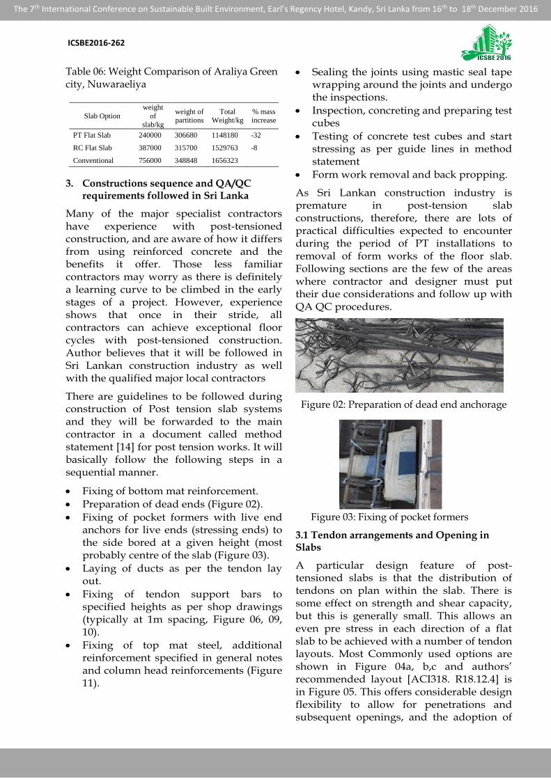
Preparation of dead ends (Figure 02).
Fixing of pocket formers with live end anchors for live ends (stressing ends) to the side bored at a given height (most probably centre of the slab (Figure 03).
Laying of ducts as per the tendon lay out.
Fixing of tendon support bars to specified heights as per shop drawings (typically at 1m spacing, Figure 06, 09, 10).
Fixing of top mat steel, additional reinforcement specified in general notes and column head reinforcements (Figure 11).
Sealing the joints using mastic seal tape wrapping around the joints and undergo the inspections.
Inspection, concreting and preparing test cubes
Testing of concrete test cubes and start stressing as per guide lines in method statement
Form work removal and back propping.
As Sri Lankan construction industry is premature in post-tension slab constructions, therefore, there are lots of practical difficulties expected to encounter during the period of PT installations to removal of form works of the floor slab. Following sections are the few of the areas where contractor and designer must put their due considerations and follow up with QA QC procedures.
Figure 02: Preparation of dead end anchorage
Figure 03: Fixing of pocket formers
3.1 Tendon arrangements and Opening in Slabs
A particular design feature of post-tensioned slabs is that the distribution of tendons on plan within the slab. There is some effect on strength and shear capacity, but this is generally small. This allows an even pre stress in each direction of a flat slab to be achieved with a number of tendon layouts. Most Commonly used options are shown in Figure 04a, b,c and authors’ recommended layout [ACI318. R18.12.4] is in Figure 05. This offers considerable design flexibility to allow for penetrations and subsequent openings, and the adoption of

ICSBE2016-262
The 7th International Conference on Sustainable Built Environment, Earl’s Regency Hotel, Kandy, Sri Lanka from 16th to 18th December 2016
differing slab profiles, e.g. from solid slabs through to ribbed and waffle construction.
Holes through pre stressed slabs can be accommodated easily if they are identified at the design stage. Small penetrations (less than 300 mm x 300 mm) can generally be positioned anywhere on the slab, between tendons, without any special requirements. Larger slab penetrations are accommodated by locally displacing the continuous tendons around the hole. It is good detailing practice to overlap any stopped off (or ‘dead-ended’) tendons towards the corners of the holes in order to eliminate any cracking at the corners. Holes are more difficult to accommodate once the slab has been cast. They can, however, be carefully cut if the tendon positions have been accurately recorded or can be identified. A better approach is to identify the possible zones where further penetrations may be required at the design stage itself. These zones can then be clearly marked on the soffit of the slab.
a. Band Only b. Uniformly distributed
c. 50% band and 50% distribution
Figure 04 a,b,c: Possible Tendon arrangements -Technical report 43 [3]
Figure 05: Band and distribution arrangement of tendons-ACI 318[2] & Technical report 43 [3]
3.2 Installation of tendons
To enhance the laying of tendons, contractor/ designer has to submit a method statement along with shop drawing for each and every tendon (Figure 06, 07). Contractor has to make sure that, given method statement is followed perfectly to overcome unwanted delays by readjustment of tendons and removal of reinforcements etc. Most probably, practical difficulties encounter over the column heads or mid spans where band and distribution tendons are crossing each other.
Figure 06: Tendon shop Drawings
3.3 Provisions for construction joints (to control restrain effects)
There are three types of construction joints (closure strips, wall infill strips or temporary release) that can be used between areas of slab. When used they are typically positioned in the vicinity of a quarter or third points of the span. The most commonly used joint is the infill or closure strip, as this is an ideal method of resolving problems of restraint, and it also provides inboard access for stressing, removing the need for perimeter access from formwork or scaffolding. Concreting in bays were introduced in Platinum Tower project in Sri Lanka to overcome difficulties arise due to lack of scaffoldings for formwork supports
a. Tendon marking

ICSBE2016-262
The 7th International Conference on Sustainable Built Environment, Earl’s Regency Hotel, Kandy, Sri Lanka from 16th to 18th December 2016
Tendon layout
b. Detailing of tendons
Figure 07 a,b,c: Tendon Layout and detail Drawings
and concreting difficulties during peak hours and at the night and also to control the restrain effects of the central core. Further, to eliminate the restrain effects at the unfavourable wall locations, temporary wall infill or column block out had to be introduced. However, in another project (Colombo tower Figure 13, 15) closer strip along the rigid central core up to level 7 was proposed to eliminate the restrain effects and gain the easy access for stressing of tendons. Following quality measures should
be whenever required in the construction of closure strips.
Figure 08 Insert tendons into ducts
Figure 09 adjusting the tendon profiles
Figure 10 Fixing of bursting reinforcements
Figure 11: Arrangement of additional reinforcements at the opening
Retain shoring until concrete in closure strip reaches specified concrete strength
Closure strip to be filled with non-shrink concrete
Roughen, clean joints and wet prior to placing concrete
Eliminate accidental misalignment between edges of slabs that are to be joined with a closure strip. Use

ICSBE2016-262
The 7th International Conference on Sustainable Built Environment, Earl’s Regency Hotel, Kandy, Sri Lanka from 16th to 18th December 2016
mechanical methods such as jacking if necessary
Provide waterproofing membrane if required for water tightness
If closure strip will be in an aggressive environment, seal anchorage pockets as per the project specifications and caulk joint all the way around with flexible sealant
Contractor shall note, that there are special shoring conditions on either side of the closure strip, especially for multi-story structures
Figure 13: Closure Strip details
Figure 14: Closure Strip within slab
Figure 15: Closure Strip at wall slab junction
3.4 Placing un-tension reinforcements
Laing of un-tension reinforcement should be done as per method statement to minimize the repetitive works. Normal practice is to lay the bottom layer first. And after installing the tendons in place, lay the top reinforcement as per reinforcement layout and general notes.
3.5 Concrete placing, curing and maximum pour size of concrete
While concreting is in progress, Care must be taken to prevent displacing of tendons and blockage of ducts (pass compress air into the ducts through one of went pipe to insure that there is no concrete leakage into the ducts), although it is easier than concreting of conventional reinforced slab as there is no reinforcement congestion. However, both the placing and curing of the concrete is similar to that of a reinforced slab. Concrete cubes are taken and cured close to the slab to enable the strength gain of the concrete to be monitored. The cubes are taken during the pour and crushed at daily intervals to monitor the strength gain of the concrete. Large pour areas are possible in post-tensioned slabs, as the application of an early initial pre stress (partial pre stressing), at a concrete strength of typically 12.5 N/mm2 (if needed only), can help to control restraint stresses due to early thermal and shrinkage (most probably due to high wind and use of high strength concrete). There are economical limits on the length of tendons used in a slab, and these can be used as a guide to estimate the maximum pour size. Typically these are 35 m for tendons stressed from one end only and 70 m for tendons stressed from both ends.
3.6 Stressing, back propping and grouting
The tendon is stressed with a hydraulic jack and the resulting force is locked into the tendon by means of a split wedge located in the barrel of the recessed anchor. At about 4 days after concreting, after achieving 28N/mm2 cube strength, (The concrete strength and tendon force will vary depending on post tension system), slab can be fully stressed in a sequence manner given in method statement, enabling the slab to be self-supporting so that formwork can be removed. While stressing is in progress, hydraulic jack is locked to predetermined force (typically 15 Tons) and resultant elongations is checked with computed elongation indicated in shop drawings (Figure 06). Care should be taken while stressing the tendons, where expected

ICSBE2016-262
The 7th International Conference on Sustainable Built Environment, Earl’s Regency Hotel, Kandy, Sri Lanka from 16th to 18th December 2016
Table 7 performance specification of grouts
Grout Performance
characteristics Test Method Acceptance Criteria
Bleed and
Segregation of grout
Inclined Tube test
,and Wick -
Induced Bleed test
Bleed water <0.3%1)
Air void :< 0.3%1)
Segregation :No
significant segregation
visible to the naked eye
Of Original Grout
Volume
Flow Time of grout Flow cone
according to EN
445
Initial Flow time :<25
Seconds
Change of flow time in
45 minutes<3 Seconds
Sedimentation of
grout Sedimentation test
variation Of density
:<5%
Corrosiveness of
grout
Chemical analysis
of grout by
qualified
laboratory
Chloride content
:<0.1%2) Of Cement
weight
Toxicity of grout
Declaration of
materiala or
chemical analysis
by qualified
laboratory
Grout shall not contain
toxic materials
Strength of grout Test According to
EN 445 Compressive strength at
7 days :> 30MPa
Volume Change of
grout Test According to
EN 445
Volume Change At 24
Hours :-0.5%to +1 1 Of
original grout volume
Setting time of
grout
Measurement of
heat of hydration
by qualified
laboratory
Start Of Setting :>3
hours
Declaration of start
,Peak ,end of setting
Water/Cement ratio
Of grout
Weight
measurement of
constituents
including liquid in
admixtures
Declaration Of water
/cement ratio of grout
Density Of grout
Volume and
weight
measurement of
grout
Declaration of density of
grout
Frost Resistance of Testing by Declaration of frost
Table 6 code provisions
Property EN 447 PTI Test
Method/Specimen
Flowability ≤25
seconds
11 to 30
seconds
Flow cone(Ø10 or
12.7mm)
Volume change 1% to
+5%
0% to
+0.1%
Plastic cylinder(100-
200mm high)
Bleed ≤2% 0% Plastic cylinder(100-
200mm high)
Strength
at 7
days
≥
27MPa ≥ 21MPa
Cube or cylinder(50-
100mm) at 28
days
≥
30MPa ≥ 35MPa
elongations could not be achieved (expected elongations is well below or above with the achieved elongation for the corresponding the jacking force). Fortunately, so far in Sri Lanka, none of the tendons were broken/ slip/blocked during the stressing (this gives an evidence that it is easily increased the jacking force up to 80% in the near future as used in other countries and ACI318.18.5.1). After Appling the pre stressing forces, close observations is required at the jacking ends for few days to ensure seating of the pre stressing tendons. It is recommended that, as soon as the formwork has been removed a secondary propping system (if required) is used until the next slab is fully stressed. However, this will be included in initial design checks/ pre stress transfer condition on the frame by taking account of the reduced concrete strength during the design process.
Figure 16: Stressing in progress
In the bonding systems, durability of PT strands, bonding between PT strand and concrete/ ducts is achieved by grouts. As bonding systems do not allow provisions for maintenance of PT strands, grouting play a major role. These grouts has a high water cementious material ratio (>0.45), resulting in low strength and high shrinkage. There is a tendency for the solids to settle, leaving a layer of water on the top. Therefore, special ingredients or treatments are needed to improve these characteristics [6]. In order to assure the quality, following proper inspection, procedures and testing (listed in table 7, 8) are essential.
Table 8 Code provisions and testing for Grouts

ICSBE2016-262
The 7th International Conference on Sustainable Built Environment, Earl’s Regency Hotel, Kandy, Sri Lanka from 16th to 18th December 2016
4. Conclusions
In the recent past, First Building in Sri Lanka (Platinum 1) with the application of Post Tension was done successfully with expected time targets and cost. During the first few floors were casted; there was a time to learn about the QA/QC procedures and detailing which were not familiar to Sri Lankan contractors. All ways contractors’ first priority was for reinforcements, but in PT slabs it is for tendons. With greater effort, the contractor was successfully trained to achieve the specific targets. Today, there are few projects already completed with the post tension slabs and few of other buildings are yet to incorporate the technology. However, Post Tension Flat slab constructions were done by specialist subcontractors in overseas countries.
References
[1]. American Concrete Institute (2005), “Building Code Requirements for Structural Concrete (ACI 318-05) and Commentary (ACI 318-05)”, 2005, Chapter 18, pp263-288.
[2]. Portland cement Association (2002), “Notes on ACI 318-02 Building Code Requirements for Structural Concrete with Design Applications”. 2002
[3]. Technical Report No.43 “Post-tensioned Concrete Floors – Design Handbook (1994)”, 2nd Edition, The concrete society, Surrey, 2005.
[4]. Sami K, Martin W (1995), “Post tension Concrete Floors”, First Edition, Hartnolls Limited, Cormwall, 1995.
[5]. BSCP115 (1969), “The structural use of pre-stressed concrete in buildings”, British Standard House, London, 1969.
[6]. Post-Tensioning Institute (2006), “Post-Tensioning Manual”, Sixth Edition, PCI, Illinois, 2006.
[7]. Bijan O Alami, “Structural Design of Post-Tension Floors”, American concrete institute, pp 31-36, 2001
[8]. Bijan O Alami, “Design of Concrete Floors with Particular Reference to Post-Tensioning”, pti technical notes, Arizona, Issue 11, 2001
[9]. Bijan O Alami, “Structural Modeling of Post-Tensioned Members”, Jounal of Structural Engineering, Vol 126, No 2, 2000.
[10]. Bijan O Alami, “Crack Mitigation Design of a post tension multi story building”, TN243, ADAPT coporation, California.
[11]. Bijan O Alami and Allan Bommer (1999), “Design Fundamentals of Post-Tensioned Concrete Floors”, Post tensioning institute, Arizona, 1999
[12]. Bijan O Alami (2001), “Nonprestressed Bonded Reinforcement in Post-Tensioned Building Design”, ADAPT Technical Publication, Issue P2-01, 2001
[13]. ADAPT - PT User Manual, Adapt Corporation, 2006.
[14]. PBL Group Thailand, Method statements
[15]. PBL group Thailand, Technical broachers
[16]. A. N. S Kulasinghe (1972), Pre Stressed concrete in industrial Buildings in Sri Lanka, Silver Jubilee of Institute of Engineers Sri Lanka, 1972
[17]. www. Kulasinghe.com.