Embed Size (px)
Citation preview

Vinod Patel is a Chief Technical Advisor,Machinery Technology, for KBR, inHouston, Texas. In his assignment, he isresponsible in the preparation and auditingof specifications, equipment evaluation,engineering coordination, and testing andinstallation startup of rotating and specialequipment. He has worked in variousapplications of rotating machinery in thepetrochemical and refinery processes
including ammonia, LNG, olefins, cat-cracking, and hydrotreatingfor domestic and international projects.Mr. Patel received B.S. and M.S. degrees (Mechanical and
Metallurgical Engineering) from Maharaja Sarajirao Universityand Youngstown University, respectively. He is a registeredProfessional Engineer in the State of Texas.
Jeffrey Feng is a Process Engineer withKBR, in Houston, Texas. He has been withKBR since 1995. He has applied dynamicsimulation in LNG, refining, olefins,ammonia, and offshore in domestic andinternational projects.Dr. Feng graduated from Texas A&M
University with a Ph.D. degree (ChemicalEngineering, 1995).
Surajit Dasgupta is the Manager ofAdvanced Process Automation and ChemicalEngineering Technology with KBR, inHouston, Texas. In his current position, hehas the supervisory responsibilities for allprojects in the area of dynamic simulation,advanced process control, operator-trainingsimulators, and real-time optimization.Dr. Dasgupta graduated from Columbia
University, in New York, with a Doctoraldegree (Engineering and Science, 1977).
ABSTRACT
Dynamic simulation with rigorous mathematical models allowsfor evaluation of compressor performance under nonsteady-stateconditions. It has become a powerful tool in the design ofcompressor antisurge protection, evaluation of operation envelope,driver size selection, field support, and troubleshooting. Recentdevelopments in the simulator technology make it possible todevelop large-scale dynamic simulation models and use them inthe entire project life-cycle.This paper discusses the basic scope of dynamic simulation,
typical application areas, and several case studies. The case studiesare based on a wide range of applications, including conceptualfeasibility study, detailed engineering, equipment specification,precommissioning, and field support. These case studies coverdifferent compressor lineups, such as axial and centrifugalcompressors and parallel operations. One example shows how adynamic model was used to identify critical design issues at theearly stage of engineering phase to avoid design or field problemsat a later date. Other examples show how dynamic simulation wasused to evaluate design alternatives and ultimately improve overallcompressor operation and protection.
INTRODUCTION
The specification of a compressor system during the designphase is often based on a set of predicted operating points fromsteady-state heat and material balance. However, a compressorsystem can experience various transient operations when it is inservice, including startup, shutdown, turndown and equipmentfailure. These operations are dynamic in nature, so a steady-statemodel may not be adequate to address issues associated withtransient operations, such as startup capability, compressor surgeprotection, and stability of operation during turndown. In thepast these issues were addressed by experience. As the industryprogresses and plant scale continues to grow, there are compellingneeds for dynamic simulation to provide a more accurate andconsistent analysis to address these issues. This is particularlyimportant for the specification of recycle loop configuration forcompressor protection because underdesign can lead to inadequateflow (surge) while overdesign can lead to excess flow (stonewall).Dynamic simulation is a tool to simulate and study process
phenomena and equipment behavior that are typically characterized
95
APPLICATION OF DYNAMIC SIMULATION IN THE DESIGN,OPERATION,AND TROUBLESHOOTING OF COMPRESSOR SYSTEMS
byVinod Patel
Chief Technical Advisor
Jeffrey FengTechnical Advisor
Surajit DasguptaSenior Technology Manager
Prakash RamdossTechnical Professional Leader
andJihongWu
Technical Advisor
KBR
Houston, Texas

by dynamics rather than steady-state. It is a critical link betweendesign and safe operation. When applied to a compressor system,dynamic simulation allows for a detailed understanding of theactual operating characteristics of the compressor over the fullrange of operation. Another area of interest is plant expansionwhere dynamic simulation can be used to identify bottlenecks inthe compressor system by simulating the performance of theexisting compressors after plant throughput changes.Before the 90s, many dynamic models were programmed in
FORTRAN, which required considerable maintenance. There werealso limitations on the numerical methods available and the abilityto link the model to a thermophysical database. Therefore, themodels were generally limited to flowsheets with a relatively smallnumber of equipment units. In addition, because the modelcomponents were developed in-house and generally considered tobe proprietary, the use of dynamic simulation in the industry wasrather infrequent at that time. In the early 90s, simulators such asSPEEDUP and OTISS became readily available, which provided aplatform to solve the basic dynamic equations and build unitoperation blocks in a more efficient, consistent way. Using thesesimulators, case studies were done for complex units (Cassata, etal., 1993). Since then, it has become a common practice in theindustry to use dynamic simulation to analyze large-scale, complexsystems where multiple compressors are closely integrated withother processing units. Examples are liquefied natural gas (LNG)refrigeration compressors and offshore gas reinjection trains.Recent advancements in simulator technology provide the userswith off-the-shelf model components for common processequipment, rigorous thermophysical database, ability to transferthe design information from a steady-state to dynamic model,utilities for graphing and tabulating results, and user-friendlyinterfaces. All these advancements have contributed to the wideruse of dynamic simulation in recent years and dynamic simulationbecoming integral to the engineering work process (Omori, et al.,2001), field support, and other stages of the plant life cycle(Valappil, et al., 2005). Table 1 lists some of the previous applicationsof dynamic simulation in the chemical process industry.
Table 1. Some of the Applications of Dynamic Simulation inthe Industry.
BASIC EQUATIONS
The core of dynamic simulation is a mathematical model thatsimulates the detailed transient behavior of equipment based onthe heat and material balance and the performance characteristics
of each equipment (Botros, et al., 1991). There are importantdistinctions between steady-state and dynamic modeling, assummarized below:
• In a steady-state model, the pressure and flow in the flowsheetare estimated based on strict heat and material balance. Therefore,in steady-state, the total mass inflow to a unit will be equal to thetotal mass outflow from the unit.
• In a dynamic model, the pressure of a unit is estimated based onaccumulation. The flow between units is estimated based onpressure-flow relationship. For example, in dynamics, the totaloutflow from a drum can be smaller than the total inflow, in whichcase the pressure of the drum starts to rise. This occurs during acompressor trip when the discharge flow is recycled back to thesuction and pressurizes the suction drum.
• When applied to process simulation, a dynamic model can predictthe intermediate process conditions when a plant is in transition fromone operating condition to another. On the other hand, a steady-statemodel can only provide a snapshot of the starting and end conditions,and cannot show the plant behavior during the transition.
APPLICATION OF DYNAMIC SIMULATIONIN COMPRESSOR PROTECTION
For a compressor, the operating characteristics are often shownin the form of a map of operating envelopes. Figure 1 is a typicalcompressor map with defined operating boundaries. The compressormanufacturer recommends a minimum flow, i.e., surge limit line(SLL) on the operating map, and generally performs a surge test atsupplier shop and in some instances retest at site to verify the surgelimit line. If the compressor suction flow falls under the SLL, surgecan occur, which is characterized by fast flow reversals that can bedetrimental to compressor components. Therefore, surge preventionis one of the key aspects of compressor protection (White, 1972).Providing a recycle valve is a common measure to maintainadequate flow, and there are general requirements on the recyclevalves in terms of capacity and stroke rate (Wilson and Sheldon,2006). For large-scale compression systems, it is now imperative touse dynamic simulation to size the recycle valves based on variousdynamic scenarios, such as startup, feed variation, turndown, andshutdown, to ensure that sizing criteria cover the most severeoperating condition rather than by experience.
Figure 1. Typical Compressor Operating Map. For Safe Operation,the Operating Points Should Be Between the Surge andStonewall Lines.
In addition to the surge limit line, the compressor manufactureroften recommends a high-flow limit on the right-hand side of theoperating map, as shown in the previous Figure 1. Excessive flowacross the compressor, referred to as stonewall, can cause vibrationand fatigue failure that can damage the entire compressor over
PROCEEDINGS OF THE THIRTY-SIXTH TURBOMACHINERY SYMPOSIUM • 200796

time. Again, dynamic simulation can be used to predict theoperating point trajectory under various transient scenarios andevaluate measures that can reduce the risk of stonewall. Forlong-term operations, the most effective means of avoidingstonewall is by fine-tuning the operating conditions to reduce theexcess inflow to the compressor. For short-term operations, forinstance after fail-open of a recycle valve, high-flow alarm and tripare often used as protection against stonewall.Another important application of dynamic simulation is to
determine the design parameters of a compressor for stable androbust operation. One of the key parameters is head-rise-to-surge.Notice that the compressor performance curves in the previousFigure 1 become nearly flat as the SLL is approached. If thecompressor curve is flat, i.e., a small head-rise-to-surge, even arelatively small disturbance can drive the compressor quicklytoward surge when the operating points are close to the SLL.Dynamic simulation can be used to analyze the sensitivity ofcompressor behavior with respect to the shape of operating curvesand determine the margin required between the operating point andthe SLL. This is discussed in more detail in one of the case studiesin this paper. Generally speaking, for a large-scale centrifugalcompressor that is used in the LNG refrigeration system, a 6 to 10percent head-rise-to-surge above a single design guarantee point isneeded for robust operation, which is also achievable based onprevious site testing results. Note that if the compressor hasmultiple design guarantee points, it is possible to have a smallerhead-rise-to-surge for some of the design points, in which case thecontrol system must be more robust to provide adequate protection.
SIMULATION MODEL
Figure 2 shows a typical single-stage compressor line-up thatincludes a suction drum, an aftercooler, and a set of recycle valves.Figure 3 shows a screenshot of dynamic model for the sameflowsheet. The simulation flowsheet, graph (showing compressorspeed in this example), and model components can be seen fromthe user interface.
Figure 2. Equipment Units in a Compressor System. TheCompressor Had a Recycle Valve CV101 to Maintain AdequateFlow During Normal Operation and a Hot Gas Bypass ValveXV101 for Additional Protection Against Surge on Coastdown.
Figure 3. Snapshot of a Compressor Simulation Model and theUser Interface.
Table 2 lists the key input data for a dynamic model of thecompression system. Notice that the list includes components suchas pipe segments, location of check valves, and instrument lags inmeasuring the process conditions. These components may not beimportant in a steady-state model since they do not affect theoverall heat and material balance, but are critical to the dynamicbehavior of the overall process.
Table 2. Key Input Data of a Compressor Dynamic Simulation Model.
Once it is developed, the dynamic model should be validatedbefore it is used for analysis. There are two aspects to validation:steady-state and transient. General guidelines on the modelacceptance criteria are provided in ANSI/ISA-S77.20 (1993). Forsteady-state, the model prediction should be within 2 percent of themeasuring instrument range for critical parameters such as flow andpressure, and for transient operations, the overall system transientcharacteristics’ time should be within 20 percent of the plantresponses. Industrial experience shows that steady-state design datacan be very closely matched with accurate dynamic models (Dukleand Narayanan, 2003). In general, steady-state validation is arequirement for all the dynamic simulation studies to verify themodel input data and the starting points of dynamic analysis.Validation under transient conditions is less frequent since it
generally requires considerable efforts in gathering data from theplant; however the authors’ experience shows that accuratedynamic models can also match good, reconciled plant data veryclosely. For example, in a recent study, a dynamic model wasdeveloped for a three-stage propane compressor that has been inoperation for several years (Figure 4). A startup case wasperformed with the model, and the results closely matched theplant data that were recorded at five-second intervals (Figure 5). Inthis example, the facility was to be expanded, and the dynamicmodel was used for analyzing the proposed design modificationsof the compressor circuit. Validating these models under thesteady-state and dynamic conditions has provided further confidenceon the validity of the model results.
Figure 4. The Startup Circuit of a Three-Stage Compressor. TheCompressor Was Started up in Total Recycle with All Three ValvesFully Open.
APPLICATION OF DYNAMIC SIMULATION IN THE DESIGN,OPERATION,AND TROUBLESHOOTING OF COMPRESSOR SYSTEMS 97

Figure 5. Comparison of Model Results with Plant Data. The ModelResults Are Shown as Curves and Plant Data Are Shown as Symbols.
STUDY APPROACH
Case Definition and Input Data
The simulation cases to be performed for a specific projectdepend on the project development stage, available input data, andproject-specific issues. Generally speaking, for a conceptual studyat the early phase of a project, dynamic simulation is used toaddress issues such as driver size and selection (Hori and Konishi,2004) and overall process configuration (e.g., single versus paralleltrains). As the project progresses to the engineering phase,additional cases are required to size recycle valves and recyclecoolers, determine startup power requirements, and evaluaterobustness of the control system. Finally, for field support andtroubleshooting, the cases are defined based on field events, oftento evaluate potential system modifications before they areimplemented at site and/or diagnose specific plant problems.Although the basic layout of the simulation flowsheet may remainthe same, the input data should be updated when more definitivedesign and operating information becomes available as the projectprogresses. Table 3 provides a summary of the input data andtypical simulation cases for different stages of the project.
Table 3. Compressor Simulation at Different Stages of ProjectLife-Cycle.
Initial Conditions
The starting conditions of dynamic simulation should be basedon the equipment design conditions or preferably the actualperformance data if they can be obtained. The initial conditionsshould cover a full range of operation with different combinationsof maximum/minimum plant throughput, cold/hot temperature,and heaviest/lightest gas composition.
CASE STUDIES
Five case studies are presented in this paper. They are selectedfrom a wide range of applications where dynamic simulation hasproved to be a useful tool. The case studies are organized based onproject life-cycle, starting from conceptual feasibility study,
through detailed engineering, and finally to field troubleshooting.Table 4 is a list of these case studies.
Table 4. List of Case Studies.
Several case studies made reference to a helper/starter motor.Figure 6 shows a typical compressor line-up where a helper/startermotor is used. In this example, two compressors are driven by aFrame 7 gas turbine. Because the standard Frame 7 gas turbine haslimited starting capacity (breakaway torque) for applications suchas for the compressor train, an electric motor or similar driver isused for startup during the acceleration phase. The motor can alsobe used during normal operation to provide additional power forthe compressors when required.
Figure 6. A Typical Compressor Lineup with Gas Turbine Driverand Helper/Starter Motor.
It is important to note that the results and conclusions from eachcase study were based on the design and operation data for aspecific application. They should not be considered as generaldesign criteria for other applications.
CASE STUDY 1—FEASIBILITY STUDY OF PARALLELREFRIGERATION COMPRESSORS
In a recent study, parallel compressor trains were proposed for alarge-scale refrigeration compression system. Due to the significantamount of capital investment involved, a feasibility study wasperformed at an early stage of the project to confirm the feasibilityof the proposed design and identify critical design issues thatshould be addressed on a priority basis.Figure 7 is a schematic diagram of the parallel compressor
trains. Each train consisted of two compressors in series, and wasdriven by a Frame-7 gas turbine and a helper/starter motor. One ofthe concerns with parallel operation was the interaction betweenthe two trains, particularly the ability to start and maintain stableoperation when the plant throughput changed or when one of thetrains tripped or restarted.
PROCEEDINGS OF THE THIRTY-SIXTH TURBOMACHINERY SYMPOSIUM • 200798

Figure 7. Parallel Refrigeration Compressor Trains. Each TrainConsisted of a Single-Stage and a Two-Stage CentrifugalCompressor, and Was Driven by a Gas Turbine and aHelper/Starter Motor.
Overview of Model
A dynamic simulation model was developed for the process. Thecompressor performance curves were based on the single-traincompressors that were in operation and of similar size. Althoughthe two trains were duplicates, it was expected that there would bedifferences in the actual performance between the trains.Therefore, deviations were imposed on the performance curves ofthe individual trains in the simulation model.
Deviations in Individual Performance Curvesand the Effects on Parallel Operation
Simulation results showed that because the two trains shared thesame suction and discharge, the overall head (i.e., pressure rise)across each train was more or less equal, but the flow distributionbetween the two trains was different due to the deviations inperformance curves (Figure 8). If the curve of compressor B (shownas curve B1) was close to that of compressor A, the difference in loadbetween the trains would be small, and both compressors wouldoperate at the same distance from the surge limit. On the other hand,if the performance curve for compressor B had a lower head and asmaller head-rise-to-surge (shown as curve B2), compressor B wouldoperate closer to the surge limit.
Figure 8. Deviation of Compressor Operating Points in ParallelTrains. If the Deviation in Individual Performance Curves WasSmall (Curves A and B1), the Operating Points of the Two TrainsWould Be Closed to Each Other. If the Deviation Was Large(Curves A and B2), the Operating Points Would Be Further Apart,with Compressor B Closer to the Surge Limit.
Typical load-sharing capability (Staroselsky and Ladin,1986; Nisenfeld and Cho, 1978) was expected to overcomesome of the differences between individual curves. However,for this application, simulations showed that there wasadditional challenge in load sharing due to the limited speedrange of 95 to 101 percent for the Frame-7 gas turbine driver.To quantify the impact of deviation in individual curves on theoverall performance of parallel train system, sensitivity caseswere performed assuming different levels of deviationsbetween the two trains. Table 5 is a summary of the sensitivitycases, and shows that the deviations in individual curves shouldbe less than 5 percent and preferably less than 2 percent toensure stable parallel operation with some operational flexibility.It is important to note that these observations are based on thisconfiguration and project-specific design data, and should notbe considered to be general conclusions that can be applieddirectly to other situations.
Table 5. Impact of Deviations in Individual Compressor Curves onParallel Operation.
Based on these results, the proposed process configuration wasfeasible if the deviations between the two compressor trains weresmall. The authors analyzed the performance data for severalfacilities currently in operation, and found that the differences inthe head curves between duplicate compressors were generally lessthan 1 to 2 percent. Therefore, it was concluded that the proposedparallel-train configuration was feasible based on the experiencewith duplicate compressors.When the project progresses beyond the conceptual phase, more
in-depth discussions are expected with the compressor manufactureron the compressor specifications, particularly deviation toleranceand expected head-rise-to-surge. The simulation model will then beupdated for design verification.
Operation Flexibility
Another objective of this study was to determine whether itwas possible to keep one compressor train running after theother train was tripped. Simulations showed that withoutcorrective actions, the remaining train could be stalled andeventually tripped due to the driver overload. Figure 9 showsthat after compressor A was tripped (curve A), the load wasinitially shifted to compressor B (curve B). This was caused bythe increase of compressor suction pressure when the forwardflow to Train A stopped after the trip. As a result, compressor Bwas not able to stay online when its gas turbine driver could notmeet the higher power demand and subsequently tripped on lowspeed. One proposed solution based on simulation results wasto install a quick closing valve at the suction of each compressortrain, so when a train was tripped the isolation valve to thattrain quickly closed to prevent overloading the remaining train.Since fast-closing isolation valves of that size have been inservice for years, the proposed solution was considered tobe feasible.
APPLICATION OF DYNAMIC SIMULATION IN THE DESIGN,OPERATION,AND TROUBLESHOOTING OF COMPRESSOR SYSTEMS 99

Figure 9. Response of Parallel Trains When One Train Is Tripped.After a Compressor Was Tripped (Curve “A”), the RemainingCompressor Could Experience a Higher Load (Curve “B”).
Driver Configuration
The final driver selection for the project was two Frame-7 gasturbines. Other configurations were considered, as shown in Figure10. Alternate 1 is using two variable speed drivers. Alternate 2 isthe final selection as shown in detail in the previous Figure 7, witheach compressor driven by its designated Frame 7 gas turbinedriver with very narrow speed variation. Alternate 3 is with bothcompressors driven by a common Frame 7 gas turbine driver withnarrow speed margin.
Figure 10. Different Driver Configurations for Parallel Operation.
Alternate 2 has been discussed previously in this paper. ForAlternate 1, simulations show that the variable speed driverprovides additional flexibility in load sharing. Therefore, thedeviation tolerance between parallel compressors can be lessstringent for Alternate 1 as compared with Alternate 2.Alternate 3 presents considerable challenges in parallel operation.
Because both compressors are on the same string, load sharingcannot be achieved by adjusting individual compressor speed.Instead, suction throttling valves have to be considered to balance theflow to each train. Using throttling valves will result in an increase in
energy consumption, which should be considered in the cost-benefitanalysis for driver selection. Increasing the margin betweenoperating points and surge limit can minimize the use of throttlingvalves in normal operation, which may be achieved by shifting theload from one section of the plant to another. One example is theLNG refrigeration system where the refrigeration load between themixed refrigerant (MR) and propane circuits can be balanced so thatall compressors are operated away from the boundary.Figure 11 summarizes the design considerations for different
driver selections. In general, driver selections can be more flexibleif there is a large head-rise to surge. In other words, the operatingconditions are further away from the operating limit (surge). Also,the deviation tolerance becomes more stringent for fixed-speeddrivers or parallel trains on a common string, which may requireshop-testing of duplicate compressors. This will have impact on theoverall schedule and economics of the project.
Figure 11. Design Considerations for Different Driver Selections.
For all three configurations discussed previously, a fast closingvalve is required for each suction and side stream to isolate atripped compressor from the remaining string. These valves alsogive field engineers a means to test and adjust the compressoroperating conditions after installation.
Overall
This case study showed a successful use of dynamic models toevaluate the feasibility of a conceptual design. In addition, criticaldesign issues were identified at an early stage of the project, sothey could be addressed promptly as the project progressed.In this case study, the dynamic simulation was completed over a
short period of time and simulation results were available forreview in a timely manner. This would not have been possible in the80s and early 90s when simulation was more resource-intensive.
CASE STUDY 2—LNG PLANTCOMPRESSORS OPERATING PROCEDUREAND ANTISURGE PROTECTION
This case study is a dynamic study performed during thedetailed engineering phase of an LNG project. The focus of thestudy was a four-stage centrifugal compressor as the main part ofthe propane refrigeration compression system (shown in Figure12). The compressor train was driven by a Frame-7 gas turbineand a helper/starter motor. The objective of the study was toverify the compressor protection system, including recycle loopconfiguration, recycle valve size, control system responsiveness,and implementation of operational procedures.
PROCEEDINGS OF THE THIRTY-SIXTH TURBOMACHINERY SYMPOSIUM • 2007100

Figure 12. Configuration of Antisurge Protection System. EachStage Had an Antisurge Valve for Protection During NormalOperation, and a Hot Gas Bypass for Protection AgainstCoastdown Surge. The LP Stage Had an Additional Bypass Valvefor Defrost Gas Startup.
Case Definitions
Below show the scenarios studied to cover all criticaloperational aspects:
• Compressor train initial startup and restart after trip• Compressor trip or emergency shut down• Failure of equipment such as loss of cooling, trip of motor, andline blockages
For each scenario, different starting conditions were usedbased on combinations of maximum/normal/minimum plantthroughput and cold/average/hot ambient temperature. Thisensured that the most critical operating case was identified.In all, over 50 simulation cases were performed as part ofthe study.
Train Startup
One of the design requirements was to use different gasmedia other than the normal gas during the initial compressorstartup. Data provided by the compressor and recycle valvemanufacturers showed that the compressor performance curvesand recycle valve capacity varied considerably as a result of thechange of gas composition. To adequately size the recyclesystem for all startup gases, a number of simulation cases wereperformed as shown below:
• Study Cases for Train Startup—• Variation of startup gas—propane, nitrogen, and defrost gas
(defrost gas is mainly methane with a small quantity of nitrogenand ethane)
• Single recycle valve for each stage• Parallel valve for the first low pressure (LP) stage• Varying valve sizes
Figure 13 shows the simulation results for variation of startupgas. When the compressor was started up with propane, the recyclevalve for the LP stage required a capacity (Cv) of 2000. However,when the compressor was started up with defrost gas with amolecular weight of 16, the recycle valve for the LP stage requireda Cv of 5000.
Figure 13. Compressor Startup with Different Gas. Startup withDefrost Gas Required a Larger Capacity in the Recycle Valve. ThisAdditional Capacity Was Provided by a Bypass Valve.
Based on the simulation results and inputs from recycle valveand control system suppliers, a parallel bypass valve for the lowpressure stage was added and final valve sizes were determinedaccordingly. The final configuration was shown in the previousFigure 12.
Emergency Shutdown
Compressor trip in the event of an emergency is a criticalscenario that requires a series of instant actions to protect thecompressor from surge during coastdown. Equipment placement,recycle line take-off and tie-in points, recycle valve size andresponsiveness, and control logics are all dynamic variables thatdetermine the effectiveness of the antisurge system. The dynamicmodel is required to precisely model the system variables as wellas the operating sequences. For this study, in the case ofemergency shutdown, a trip signal would initiate the followingactions/responses:
• Trip of helper motor• Trip of gas turbine, with the decay of turbine output as a functionof fuel valve closure rate
• Energizing the actuators for the recycle valves and then openingof the recycle valves
• Closure of isolation valves at the compressor suction anddischarge based on the valve stroke time
From the study, due to the constraints on equipment placement,there was a large system volume in the compressor discharge. Itwas found that the original configuration with single recycle loopfrom the compressor recycle cooler was unable to depressure thecompressor discharge quickly enough to prevent coastdown surge.Based on the dynamic study results and consultation with thecompressor and control system suppliers, hot gas recycle valveswere added. These hot gas bypass valves were connected directlyto the compressor discharge line and provided an additional recycleloop to depressure the compressor discharge quickly. The finalconfiguration was shown in the previous Figure 12.
Surge Protection from Equipment Failure
After the configuration of antisurge circuit was determined basedon startup and shutdown requirements, additional simulation caseswere performed to evaluate the effectiveness of the protection schemefor other transient events, such as loss of air coolers and blockage ofone of the lines connected to the compressor. The simulation resultswere reviewed by the compressor and control system suppliers, and itwas concluded that the combination of cold and hot recycle valves asproposed was adequate for the transient cases identified.
APPLICATION OF DYNAMIC SIMULATION IN THE DESIGN,OPERATION,AND TROUBLESHOOTING OF COMPRESSOR SYSTEMS 101

Site Observations
The plant has been in operation for over two years. Site feedbackindicated that the compressor protection scheme as determinedbased on the dynamic study results was effective in protecting thecompressor for the full range of operation.
CASE STUDY 3—RESTART OF COMPRESSORS
Restarting a compressor in a safe, efficient way is important inminimizing the downtime of a facility. There are issues specific tocompressor restart, such as power and torque capability of thestarter motor and permissible system restart pressure. A typicalrestart curve is shown in Figure 14. The top curve is the torquegenerated by the motor, whereas the bottom curve is the loadtorque from the compressor train during the acceleration phase.The motor torque must be greater than the load torque with somemargins; otherwise the motor may stall before the final speed isreached. Notice that the closest approach between the curves isoften at an intermediate speed. To confirm the ability to restart thecompressor, dynamic simulation is often used to predict the loadtorque curve for the entire acceleration phase.
Figure 14. Startup Curves of Compressor with Starter Motor. TheCircle Shows the Closest Approach Between the Two Curves at anIntermediate Speed.
Power and Startup Pressure
In this case study, the restart of a propane refrigerationcompressor was analyzed. The configuration of the compressorsystem was shown in the previous Figure 12. As required, a startermotor was used for restart. Simulations showed that the powerrequirement of the motor was a function of the initial systempressure, and a motor of greater than 55 MW would be needed torestart from the settle-out pressure of 10 bara (Figure 15).
Figure 15. Increase of Power Requirement with Higher StartupPressure. The Curve Shows the Motor Power as a Function ofStartup Pressure Based on Simulation Results. To Restart theCompressor Without Depressuring (Full-Pressure Restart)Required a Starter Motor of Greater than 55 MW.
Economic Considerations
For similar propane compressors currently in operation, themotor size is less than 20 MW, so the system must be depressuredprior to the restart. Depressurization results in a loss of refrigerant
that is of high value and limited supply, as well as an extendedshutdown of the system. The results of this case study show that byincreasing the motor size to over 55 MW, it is possible to restart thecompressor without depressurization. Economic analysis shouldbe done, case-by-case, to determine whether the increase in unitrun-time and reduction in loss of refrigerant can offset the cost ofa larger motor and the upgrade of power generation. For this casestudy, it was concluded that the large motor size could be justifiedbased on the overall cost matrix.This case study demonstrated that dynamic simulation was able
to provide valuable information to address issues associated withthe compressor restart and assist in the specifications of compressordriver. It is important to note that these simulation results werebased on design information specific to this project and should beverified on a case-by-case basis for other systems.
Other Issues in Compressor Restart
Besides power requirement, another important issue is theability to restart the compressor without surging during the entireacceleration phase. The previous Case Study 2 has shown the useof dynamic model to size the recycle valve for startup. Wherepractical, the simulation should be extended to cover the entirerestart procedure, including initial acceleration, commissioning ofantisurge control, pressurization, establishing forward flow, andfinal compressor loading.
CASE STUDY 4—CONTROL SYSTEM CHECK-OUTBEFORE COMMISSIONING
This case study was based on a recent project where an offshoreoil platform was constructed and commissioned. Figure 16 is aschematic diagram of the processing units on the platform, withdetails on the gas reinjection compressor trains. The incoming fluidto the platform was a mixture of gas, oil, and water from differentproduction wells. The gas was separated from oil and water in twoparallel separators, and then compressed from 10 bara to 200 baraby two parallel reinjection compressor trains. Each train had threecompression stages and was driven by a variable-speed gas turbine.The high-pressure gas was eventually reinjected back to the wellsto maintain reservoir pressure.
Figure 16. Offshore Gas Reinjection Compressor Trains. AllInstrumentations (PI, TI and FI) Shown on the Graph AreConnected to the Antisurge and Capacity Controllers. The OverallSystem Included Antisurge Control, Capacity Control, LoadSharing, and Pressure Override.
For this facility, a stable pressure at the separators was importantin minimizing the slugging in the subsea flowlines betweenproduction wells and platform. Slugging is a phenomenoncharacterized by alternating plugs of liquid and gas bubbles, whichis a common occurrence in multiphase pipelines and often causesoperational problems such as pressure surge in the process system.In the control system that was originally proposed in the designphase, the separator pressure was maintained by varying the speedof the gas turbines. For instance, if the output from the productionwells went down and caused a reduction in the separator pressure,the gas turbines would slow down and the compressor trains wouldoperate at a low speed until the separator pressure recovered.
PROCEEDINGS OF THE THIRTY-SIXTH TURBOMACHINERY SYMPOSIUM • 2007102

Potential Risk of Unstable Operation
The contractor that built the facility was required to demonstratestable, uninterrupted operation for a sustained period of timeduring the commissioning phase. The contractor considered thereinjection compressors to be the critical element in achievinguninterrupted operation, because:
• A trip of reinjection compressor was common based on pastexperience, and
• A shutdown of the compressor trains would automatically stopthe production from the platform.
Further analysis identified several risk factors in maintaining stableoperation of compressor trains, as listed below:
• The operating conditions differed from the design conditionsduring the commissioning. The facility would be operated at about 50percent of the design throughput since all the production wells werenot yet connected. It was not clear whether the parallel compressortrains would operate in a stable manner at a low throughput.
• The gas flow to the platform could be unstable during thecommissioning, since the wells were being tested and the numberof wells that were connected to the platform could change at anygiven time. It was not clear whether the control system as proposedwould be able to maintain a stable separator pressure while someof the wells were disconnected from the platform for testing.
• The gas compositions to the two parallel trains were differentdue to the alignment of wells and the asymmetry in pipe routingon the platform. This presented additional challenges in parallelcompressor operation.
Enhancement of Control Scheme
To evaluate these risk factors and identify improvement to thecontrol system that would mitigate the risks, the contractor performeda dynamic simulation for the entire platform, with emphasis on theoperation and protection of the reinjection compressor trains. One ofthe simulation cases was a shutdown of half of the production wells.Figure 17 shows that, based on the original control scheme where thepressure was maintained by varying the compressor speed, theseparator pressure could drop to 8 bara after a sudden reduction in gasthroughput. The pressure of 8 bara would result in a low-pressurealarm, which presented a risk of compressor trip on low-pressure. Theresults were reviewed by the supplier of the control system, and withtheir collaboration a pressure override control (POC) was added to thecontrol system. The POC would open the recycle valves of the firstcompressor stage when the separator pressure started to decrease. Asconfirmed by simulation results shown in Figure 17, the POCminimized the pressure fluctuation in the separator and reduced therisk of compressor trip on low-pressure.
Figure 17. Minimizing Pressure Fluctuation with Override Control(POC). The POC Opened the First Stage Recycle Valves When thePressure Started to Drop.
Load Sharing
Dynamic simulation was also used to fine-tune the loadsharing scheme. Simulation showed that after a reduction of gasthroughput, the compressor trains would operate in partial recycle.Without load sharing, it was possible that the opening of recyclevalves differed considerably between the parallel trains due toasymmetry in piping and gas feed. This can be seen in Figure 18:Without load sharing, the recycle valve on Train A was almost fullyopen whereas the one for Train B was almost closed. As a result,Train A would be vulnerable to surge if the gas throughput wasfurther reduced. Figure 18 also showed that if load sharing was used,the opening of recycle valves of the two trains would be about equal,so both recycle valves had additional capacity to handle furtherdisturbance. The effect of load sharing can also be observed in Figure19 where the compressor operating points predicted by the simulationmodel were plotted: Both compressors initially operated near thenormal speed. After a reduction of throughput, both compressorsmoved to a lower speed. Without load sharing, the operating pointsbetween the two parallel compressors were far apart, with compressorA near the operating boundary. On the other hand, if load sharing wasused, the operating points of the two trains were closer, and bothtrains had room to accommodate further reduction in the gasthroughput. The simulation results were given to the control systemsupplier for their use in configuring the load sharing scheme.
Figure 18. Improving Compressor Protection with LoadingSharing. After a Reduction in Gas Feed, Both Compressors WereOperated in Recycle. Without Load Sharing, the Recycle Valve forCompressor AWas Close to Full Open, So the Compressor BecameVulnerable to Surge If There Was Further Reduction in Gas Feed.
Figure 19. Improvement of Parallel Compressor Operation withLoad Sharing. With Load Sharing, the Operating Points of BothCompressors Were Away from the Operating Boundaries, WhichProvided Additional Operation Flexibility.
Pretuning Controllers
In addition to the control system for the compressor trains,dynamic simulation was used in pretuning the controllers in otherunits to minimize the risk of unstable operation. Simulation resultsshowed that pretuning the controllers for the separators reduced thefeed fluctuation to the gas compressors and helped achieve stable,uninterrupted operation.
APPLICATION OF DYNAMIC SIMULATION IN THE DESIGN,OPERATION,AND TROUBLESHOOTING OF COMPRESSOR SYSTEMS 103
Overall
With the assistance of dynamic simulation, potential risk factorswere evaluated prior to the commissioning and solutions weredeveloped to mitigate risk. The facility was successfully started up,and turned over to the owner shortly after the startup.
CASE STUDY 5—FINE-TUNING COMPRESSORANTISURGE CONTROL
Recently, dynamic simulation was used to address issues associatedwith compressor services on separate line-up and drivers. Figure20 is a schematic diagram of the MR compressor train in a facilitythat was recently constructed. MR is a mixture of methane, ethane,propane, and nitrogen. The compression system included three MRcompressors in series (K-001, K-002, and K-003). There wereantisurge controllers and recycle valves for each compressor.One key feature in the configuration was that the LP MR andmedium-pressure (MP) MR compressors were on one string with agas turbine, but the high-pressure (HP) MR compressor K-003 wason another string with the propane compressor K-004 and anothergas turbine. As a result, there were considerable interactionsbetween the two rotating assemblies.
Figure 20. Compressor Line-Up with the High-PressureCompressor K-003 Tied to the Propane Compressor K-004. WhenK-004 was Tripped, the Recycle Valve for K-003Was Tripped FullyOpen, Which Resulted in a Reduction in Flow to K-001 and K-002over a Short Period of Time.
Field Observations
The design intent was to keep the LP and MP MR compressors(K-001 and K-002) in recycle if the HP MR compressor andpropane compressors (K-003 and K-004) were shut down.However, shortly after the plant was started up, it was reportedthat when the propane compressor tripped, the LP and MP MRcompressors quickly approached surge and were subsequentlytripped on surge count. Further analysis of site data showedthat the flow across the LP and MP MR compressors (K-001 andK-002) was reduced quickly when the recycle valve for the HPMR compressor (K-003) was tripped open. Due to the delays inthe actuator response and valve stroke, the original surgedetection and prevention measures were not adequate.Considering that the compressors could be damaged by a smallnumber of surge events, there was a compelling need fordeveloping an improved control solution.
Modifications
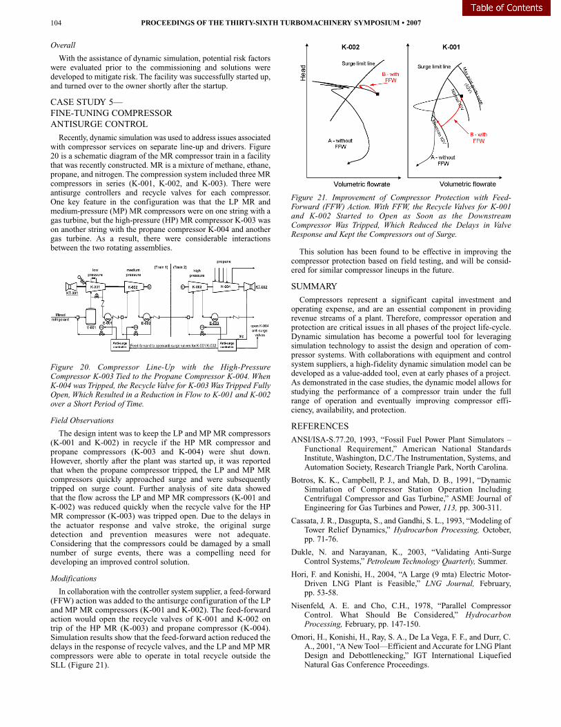
In collaboration with the controller system supplier, a feed-forward(FFW) action was added to the antisurge configuration of the LPand MP MR compressors (K-001 and K-002). The feed-forwardaction would open the recycle valves of K-001 and K-002 ontrip of the HP MR (K-003) and propane compressor (K-004).Simulation results show that the feed-forward action reduced thedelays in the response of recycle valves, and the LP and MP MRcompressors were able to operate in total recycle outside theSLL (Figure 21).
Figure 21. Improvement of Compressor Protection with Feed-Forward (FFW) Action. With FFW, the Recycle Valves for K-001and K-002 Started to Open as Soon as the DownstreamCompressor Was Tripped, Which Reduced the Delays in ValveResponse and Kept the Compressors out of Surge.
This solution has been found to be effective in improving thecompressor protection based on field testing, and will be consid-ered for similar compressor lineups in the future.
SUMMARY
Compressors represent a significant capital investment andoperating expense, and are an essential component in providingrevenue streams of a plant. Therefore, compressor operation andprotection are critical issues in all phases of the project life-cycle.Dynamic simulation has become a powerful tool for leveragingsimulation technology to assist the design and operation of com-pressor systems. With collaborations with equipment and controlsystem suppliers, a high-fidelity dynamic simulation model can bedeveloped as a value-added tool, even at early phases of a project.As demonstrated in the case studies, the dynamic model allows forstudying the performance of a compressor train under the fullrange of operation and eventually improving compressor effi-ciency, availability, and protection.
REFERENCES
ANSI/ISA-S.77.20, 1993, “Fossil Fuel Power Plant Simulators –Functional Requirement,” American National StandardsInstitute, Washington, D.C./The Instrumentation, Systems, andAutomation Society, Research Triangle Park, North Carolina.
Botros, K. K., Campbell, P. J., and Mah, D. B., 1991, “DynamicSimulation of Compressor Station Operation IncludingCentrifugal Compressor and Gas Turbine,” ASME Journal ofEngineering for Gas Turbines and Power, 113, pp. 300-311.
Cassata, J. R., Dasgupta, S., and Gandhi, S. L., 1993, “Modeling ofTower Relief Dynamics,” Hydrocarbon Processing, October,pp. 71-76.
Dukle, N. and Narayanan, K., 2003, “Validating Anti-SurgeControl Systems,” Petroleum Technology Quarterly, Summer.
Hori, F. and Konishi, H., 2004, “A Large (9 mta) Electric Motor-Driven LNG Plant is Feasible,” LNG Journal, February,pp. 53-58.
Nisenfeld, A. E. and Cho, C.H., 1978, “Parallel CompressorControl. What Should Be Considered,” HydrocarbonProcessing, February, pp. 147-150.
Omori, H., Konishi, H., Ray, S. A., De La Vega, F. F., and Durr, C.A., 2001, “A NewTool—Efficient andAccurate for LNG PlantDesign and Debottlenecking,” IGT International LiquefiedNatural Gas Conference Proceedings.
PROCEEDINGS OF THE THIRTY-SIXTH TURBOMACHINERY SYMPOSIUM • 2007104

Staroselsky, N. and Ladin, L., 1986, “More Effective Control forCentrifugal Gas Compressors Operating in Parallel,”Presentation at the International Gas Turbine Conference andExhibit, Germany.
Valappil, J., Messersmith, D., and Mehrotra, V., 2005, “LNGLifecycle Simulation,” Hydrocarbon Engineering, October,pp. 27-34.
White, M. H., 1972, “Surge Control for Centrifugal Compressors,”Chemical Engineering, December, pp. 54-62.
Wilson, J. and Sheldon, A., 2006, “Matching Antisurge ControlValve Performance with Integrated Turbomachinery ControlSystem,” Hydrocarbon Processing, August, pp. 55-58.
BIBLIOGRAPHY
Henderson, P., Hazlett, J., and Schindler, H., 2003, “FortuneTeller,” Hydrocarbon Engineering, May, pp. 103-106.
ACKNOWLEDGEMENT
The authors would like to thank David Coyle, of KBR, for histechnical review and insights, as well as many individuals withinthe company whose contributions in various dynamic simulationprojects made this paper possible. The authors would also like tothank John Dugas, Jr., of the Turbomachinery SymposiumAdvisory Committee, who was the monitor for this paper.
APPLICATION OF DYNAMIC SIMULATION IN THE DESIGN,OPERATION,AND TROUBLESHOOTING OF COMPRESSOR SYSTEMS 105

PROCEEDINGS OF THE THIRTY-SIXTH TURBOMACHINERY SYMPOSIUM • 2007106