Embed Size (px)
Citation preview

10th International Conference on Concrete Block Paving Shanghai, Peoples Republic of China, November 24-26, 2012
1
Application of Concrete Block Paving in Urban Light Rail Transit – Problem & Solutions Case Study
Prof. Ilan Ishai
Dept. of Civil & Environmental Engineering, Technion, Haifa 32000, Israel Tel: +972-52-2539668, Fax: +972-9-7714198, E-mail: [email protected]
Eng. Adar Tsubery
Design Manager, Ashtom – Jerusalem Light Rail Transit (JLRT) Tel: +972-54-3394509, Fax: +972-3-5326414, E-mail: [email protected]
Mr. Dan Tamir
Inspection Manager Area 5 - Jerusalem Light Rail Transit (JLRT) Tel:+372- 5474831 , E-mail: [email protected]
SUMMARY
As a part of the Transportation Master Plan for the city of Jerusalem, a network of Light Rail Transit (JLRT) lines is planned. The first line is now in its first year of service. It is 13.8 km. long, and it contains 23 stations and 4 "Park and Ride" facilities. Among the different solutions for the upper pavement structure inside the Swept Path this JLRT line, the Concrete Block Paving (CBP) technology was selected for most of the length. The following pavement structure was suggested for the JLRT sections: 8 cm of Concrete Block Pavers, 3 cm of Sand Bedding Layer, 7 cm of Controlled Low Strength Material (CLSM) and 40 cm of concrete Slabs (as also designed to support the rail tracks). As for the confinement and lateral support of the CBP structure against the rails, a modular confining element was installed to "encapsulate" the track rails, and to provide the proper confining and supporting unit. This element is made from a "Filler Block" dense-rigid rubber. Due to the uniqueness of this application, and in order to validate the vertical and horizontal stability and sustainability of the CBP structure, an experimental test track was constructed. Several in-situ non-destructive tests are being performed, such as: Loading bearing test; Heavy Weight Deflectometer test; and stress-deformation measurements under actual vehicle movements, using pre-installed pressure cells and strain gauges. In general all test results have indicated high stability of the CBP structure. This verified the design assumptions that were further preserved during construction. This was presented during the 9th International CBP Conference in Argentina. After the construction of the swept path structure, the condition of the track and its pavement support was tested by intensive movements of pre-loaded actual trains at variable speeds. Surprisingly, it was found that in at different sections, especially at curved tracks, the first raw of blocks, adjacent to the rails, was tilted and up heaved from the paver surface. This distress mode was carefully studied and several solutions to the problem were suggested. These solutions were tested both in one-to-one laboratory scale dynamic tests and also under actual train rides. This paper summarize and outlines in details the essence of the problem, the measurement of track and CBP response under train traffic, the proposed solutions, the results of the dynamic

10th International Conference on Concrete Block Paving Shanghai, Peoples Republic of China, November 24-26, 2012
2
laboratory track testing, and the selection of the best solution that was successfully implemented along the track line.
Keywords: Light Rail Transit, Swept Path, CBP Solution, Blocks Upheaval, Dynamic Testing, Pavement Instrumentation THE JERUSALEM LIGH RAIL TRANSIT (JLRT) As a part of the Transportation Master Plan for the city of Jerusalem, a network of Light Rail Transit (LRT) lines is planned. The first line, stretches from "Pizgat Zeev" in the north to "Mount Herzl" in south, was just recently constructed.. This LRT line is 13.8 km. long, and it contains 23 stations and 4 "Park and Ride" facilities. The Concessionaire was chosen in 2002 – the "CityPass Consortium", comprised of Connex Transport AB (from the international Vivendi Group), and the renowned French train manufacturer Alstom; and two Israeli companies: Ashtrom Construction and Infrastructures, and Pollar Investments. CityPass undertook to build the first line, and to operate it for a period of 30 years in accordance with the terms defined in the agreement with the government. Work by the Concessionaire was started in 2005, experimental train ride were started in April 2010, and the inaugural of the first commercial trip along the JLRT system was taken place in August 2011 (see Figure 1):
Figure 1: Light Train in operation one month after opening to service (September 2011)

10th International Conference on Concrete Block Paving Shanghai, Peoples Republic of China, November 24-26, 2012
3
Among the different solutions for the upper pavement structure inside the Swept Path of the JLRT line, the Concrete Block Paving (CBP) technology was selected for most of the line length. Other surface solutions, like decorative natural stone flags, are adopted in the old section of Jaffa Street. BASIC PRELIMINARY CBP STRUCTURE DESIGN As presented in the 9th International conference on Concrete Block Paving and before (Refs. 1,2), the basic preliminary design of the upper Concrete Block Pavement (CBP) structure inside the Swept Path was set in July 2007. According to traffic forecasts along the JLRT line, and based on the "Guidelines for the Design of Urban Streets" set by the Ministry of Housing and Construction (3), the design traffic loading were set between "Medium Light" and "Heavy" Traffic Categories. These categories are equivalent to 3.6x10⁵ – 1.5x10⁷ coverages of 18,000 lbs Standard Axle Load in the critical lane for a 20 years design period. Accordingly, the following pavement structure was suggested for the JLRT sections that are to be paved with CBP :
Concrete Block Pavers - 8 cm. Sand Bedding Layer - 3 cm. CLSM - 7 cm.
Concrete Slabs - 40 cm. Type A Subbase Layers - Varies According to Subgrade properties
A typical cross section of the JLRT pavement structure is presented in Figure 2:
Concrete B 40
Foundation Slab
Track Slab
Subgrade
Type A Subbase Layers
Concrete Pavers Bedding Sand
CLSM 3-7 MPa
Figure 2: Typical cross section of the JLRT pavement structure
Rail, Bolts & Caps
Rail Rubber Encapsulation

10th International Conference on Concrete Block Paving Shanghai, Peoples Republic of China, November 24-26, 2012
4
In the design documents it was clearly specified that the materials & construction of the CBP structure above the CLSM (Controlled Law Strength Concrete) layer should be fully comply with the Israeli Standards: I.S. 1571, and I.S. 8 (4,5). ORIGINAL AND MODIFIED LAYING PATTERNS As originally designed, the first two sections of the JLRT line were paved using 20x10x8 surface "splitter pavers" in a herringbone pattern, confined by a "piano" pattern of 13x10x6 or 20x10x6 edge pavers near the rails. It should be mentioned that due to the rail bolts and plastic cover caps constraint, the edge piano pavers were 6 cm. thick, while the inner herringbone pavers were 8 cm. thick. This creates severe construction difficulties due to the two thickness levels of both the pavers and the bedding sand, and also to the weak support created by the bolt cover caps. At a later stage, a proper solution was found to modify the plastic caps for lower coverage of the rail bolts. Under this solution it was possible to install 8 cm. blocks above the caps, even with a minimal thickness of sand layer. Therefore, the modified final CBP structure was composed of a complete herringbone laying pattern between the rails in the entire width of the Swept Path (with 20x10, 10x10, and 16x10 cm blocks), using a uniform block thickness of 8 cm., as shown in Figure 3:
* 16x10x8 cm blocks
Rail Rubber Encapsulation
Figure 3: The final modified laying pattern solution for CBP in the JLRT Swept Path

10th International Conference on Concrete Block Paving Shanghai, Peoples Republic of China, November 24-26, 2012
5
VALIDATION BY MECHANICAL FIELD TESTING Background Due to the weakness point that may be created above the bolt cover caps in any of the CBP thicknesses and laying pattern solutions, and in order to validate the sustainability of the rail encapsulation confinement solution (see Figures 2 and 3), it was decided to perform mechanical repeated loading tests on actual test tracks that will be constructed according to the final recommended solution. The mechanical tests were designed to simulate the repeated passes of vehicle wheels under actual range of traffic loading. Generally, the tests performed on old constructed JLRT line sections as well as on an experimental test tracks that were constructed to simulate the entire width of the Swept Path, with a length of about 150 meters. Each test and measurements were performed on at least three typical points: Adjacent to the rail - Above a cover cap and between caps, and in the middle of the track between caps. Mechanical Testing Performed The following tests were outlined and performed: • Static Plate Loading Bearing Test: This test is designed to evaluate the static bearing
capacity of the CBP and its confinement system for restraining both vertical and horizontal displacements. Generally, the 20 cm. diameter plate was loaded at intervals with recovery after initial intervals and at the end of the test, up to a contact stress of about 7 kg/cm2 (0.7 MPa).
• Falling Weight Deflectometer (FWD): This test provided a tool for evaluating the dynamic response of the CBP structure by measuring the elastic deflections resulting from a drop of a heavy weight on the pavement surface. Deflection monitoring at several offset points provides a mean for characterizing the lateral deflection-basin beneath the pavement. The test was performed using a 30 cm diameter plate. The falling weights were dropped at increasing loading (combinations of heights and dead loads) intervals, until reaching a dynamic load of 7,500 kgf (as standard in Israel for FWD tests on top of the asphaltic surface course in highways).
• Direct Stress Measurements (using pressure cells) under intervals of repeated movements of actual vehicles, at variable loading levels (a private car and a heavy truck). This enabled the determination of the mechanical response of the CBP system in 1:1 scale under actual loading conditions.
• Visual inspection of repeated moving truck loading (38-40 tons) up to 60 coverages along 40 meters path. Loading configuration was: Left wheels path - adjacent to the rail above bolts and caps; Right wheels path - in the middle between the two tracks.
The performance of a typical mechanical field tests (FWD) is described in Figure 4:
Figure 4: Performing the Falling Weight Deflectometer Test (FWD) on JLRT CBP surface

10th International Conference on Concrete Block Paving Shanghai, Peoples Republic of China, November 24-26, 2012
6
The conclusions drawn from the analysis of the mechanical field testing, is that the CBP structure in the JLRT Swept Path possesses relatively high bearing capacity, and it is very well supported by the lower structure as well as by the special confinement of the unique rigid rubber encapsulation system. The tests also confirmed that the bolt cap does not create any weak area in the CBP structure. The very weak strip created by a perforated drainage pipe was very well located. This drainage system was replaced by a better structural solution. In general, it is expected that the early life low mutual vertical load transfer of the CBP structure, will be overcame by the time and traffic-related "lock-up" process of the CBP structure. In any case, the early life vertical load transfer between the blocks and the encapsulation system was found to be quite sound and solid. It was found to be quite comparable to, and in several cases even stronger than, that in the center between the rails. BLOCKS TILTING INSIDE THE RAIL TRACKS In April 2010, after the completion of several track segments along the JLRT line, specially loaded trains were operated daily at different speeds and under different braking conditions. This was aimed to verify the stability of the tracks and their support system. Two months later, rotational movement and upheaval (lift-up) of edge blocks near the rails were observed. In details, the following were occurred (see Figures 5 and 6): • The edge blocks (both parallel and perpendicular to the rail) inside the test track were
moved upward by a rotational tilt distortion. Blocks were rotated and lifted up to 1-3 cm at their far edges. No blocks movement or distortion was observed in the middle of the track. This phenomenon was intensified in curved tracks as compared to straight ones.
• No movement, or any distortion, was observed in the edge blocks adjacent to the same rails outside the test track.
Figure 5: Rotational movement and upheaval of edge blocks near the rails inside the tracks - in a straight line
RAIL
BITUMEN PLUGS

10th International Conference on Concrete Block Paving Shanghai, Peoples Republic of China, November 24-26, 2012
7
Several distorted blocks were carefully removed and the condition of the bedding layer and joint sand were examined. The following was found: • The top surface of the bedding sand was found leveled and very stable. • Sufficient joint sand was found in the interface between the blocks and the rigid rubber
rail encapsulation, and also in the joints between the blocks. Due to the repeated rotational vibrations some of the joint sand dropped down on the bedding surface. This means that continuous block-to-block, and block-to-edge contacts were existed between the track rails.
DYNAMIC RAIL RESPONSE UNDER ACTUAL TRAIN MOVEMENT General Description In order to find the magnitude of the actual dynamic response of the track-wheel system during train movement, specially designed test series were performed during November 2010 in order to measure the actual rail deformations and strains (horizontal and vertical) generated by the riding and braking of fully loaded trains (6,8). Horizontal deformations were also measured in exposed vertical surfaces of the rubber encapsulation and first adjacent blocks. Measurements were made at four locations (A to D), either near the anchoring bolts of the rail or between two anchoring bolts. The measurements were performed under complete stop, under three train velocities – 20, 40 and 60 km/hr, and under regular and emergency braking.
Figure 5: Rotational movement and upheaval of edge blocks near the rails inside the tracks - in a curved line
RAIL
BITUMEN PLUGS

10th International Conference on Concrete Block Paving Shanghai, Peoples Republic of China, November 24-26, 2012
8
The deformations were measured by electronic transducers and the strains by electronic strain gages. All data were monitored and collected by an electronic data logger system. Typical Measurement Configuration Horizontal deformations were measured at the top of the rail, in both sides. Vertical deformations were measured at the foot of the rail, in both sides, as illustrated in Figure 6A. Vertical strains were measured at the vertical support of the rail, in both sides. Horizontal strains along the direction of the track were measured at the horizontal foot of the rail, in both sides, as illustrated in Figure 6B.
Typical track instrumentations and monitoring process are shown in Figures 7 and 8:
A
Inside the track
Outside the track
Vertical rail
support B
Figure 6: Configuration of deformation and strain measuring points in the rail
Figure 7: Final installation of deformation transducers and strain gages in a measuring location

10th International Conference on Concrete Block Paving Shanghai, Peoples Republic of China, November 24-26, 2012
9
Typical Results and Interpretation Figure 9 illustrates the static deformations measured at location A, directly under the train wheels at stop. Figure 10 illustrates the maximum dynamic deformations measured as a function of train velocity in the measuring location (see also Figure 6):
Pictures 8: Actual simultaneous monitoring of strains and deformations with the data logger in measuring location A under train movement
Figure 9: Static deformations measured at location A directly under the train wheels at stop

10th International Conference on Concrete Block Paving Shanghai, Peoples Republic of China, November 24-26, 2012
10
Figure 11 illustrates the static strains measured at location A, directly under the train wheels at stop. Positive values mean tension condition at the measurement surface, and negative values mean compression.
The results obtained at locations B, C and D usually follow the same trends as measured and illustrated above for point A. It should be also stressed that, based on a precise measurement of the center of the loading wheel path of the trains (as clearly marked on the top of the rail, see Figure 12), it was found that there exists an asymmetric loading and eccentricity of 2.5 cm with respect to the axis of the vertical rail support, as also shown in Figure 12.
Point A.Displacement vs Velocity
-0.80
-0.60
-0.40
-0.20
0.00
0.20
0.40
0.60
20 40 60
Velocity, km/h
Dis
plac
emen
t,mm
Ch1-maxCh4-maxCh2-maxCh3-max
Figure 10: Maximum dynamic deformations measured as a function of train velocity in location A
Figure 11: Static strains measured at location A directly under the train wheels at stop
10th International Conference on Concrete Block Paving Shanghai, Peoples Republic of China, November 24-26, 2012
11
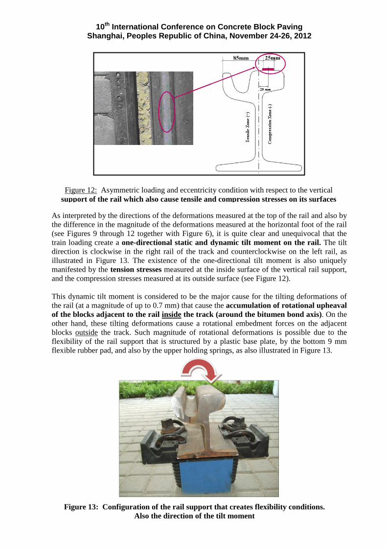
As interpreted by the directions of the deformations measured at the top of the rail and also by the difference in the magnitude of the deformations measured at the horizontal foot of the rail (see Figures 9 through 12 together with Figure 6), it is quite clear and unequivocal that the train loading create a one-directional static and dynamic tilt moment on the rail. The tilt direction is clockwise in the right rail of the track and counterclockwise on the left rail, as illustrated in Figure 13. The existence of the one-directional tilt moment is also uniquely manifested by the tension stresses measured at the inside surface of the vertical rail support, and the compression stresses measured at its outside surface (see Figure 12). This dynamic tilt moment is considered to be the major cause for the tilting deformations of the rail (at a magnitude of up to 0.7 mm) that cause the accumulation of rotational upheaval of the blocks adjacent to the rail inside the track (around the bitumen bond axis). On the other hand, these tilting deformations cause a rotational embedment forces on the adjacent blocks outside the track. Such magnitude of rotational deformations is possible due to the flexibility of the rail support that is structured by a plastic base plate, by the bottom 9 mm flexible rubber pad, and also by the upper holding springs, as also illustrated in Figure 13.
Figure 12: Asymmetric loading and eccentricity condition with respect to the vertical support of the rail which also cause tensile and compression stresses on its surfaces
Figure 13: Configuration of the rail support that creates flexibility conditions. Also the direction of the tilt moment

10th International Conference on Concrete Block Paving Shanghai, Peoples Republic of China, November 24-26, 2012
12
PROPOSED DAMAGE MECHANISM AND SUGGESTED SOLUTIOS
Based on many visual observation and the actual field testing and measurements under moving trains, a rational mechanism was adopted for the tilting and lift-up of blocks, as described in the following Figure 14. This mechanism can be described as follows:
Due to the eccentricity of the applied wheel load on the rail, and the horizontal forces and deformations generated by the train wheels (especially in curved tracks), a tilting moment is developed. Transferred by the rigid rubber encapsulation (filler block), the vertical and horizontal rail deformations that developed (in a magnitude between 1-2 mm) cause an upward tilting force on the first row of block adjacent to the rail inside the track . Since the upper corner of the block is strongly glued to the rail by the bitumen plug, this joint serve as a rotation axis for the block. With the repeated wheel loading and tilting moment, the other side of the block starts to lift up (while pushing and bulging the bitumen plug to the rail), without the ability to descend down back due to the joint sand that seeped down by the vibration, and also due to the contact friction with adjacent blocks. Under these conditions the accumulative tilt and lift up of the first row of blocks is quite imminent. This mechanism is intensified in curved tracks, where the horizontal rail deformations are much larger.
Accordingly, several solutions ("Bench Tests"). were suggested and tried in actual JLRT line sections under the pre-service experimental train rides Among them were: applications of several liquid strong glues, isolation between the bitumen plug and the first block by metal strips or by durable lubricants, and total removal of the bitumen plug. The Bench Tests results
INNER TRACK
PUSING AND BULGING THE BITUMEN PLUG
OUTER TRACK
TILTED BLOCK
PUSING BY THE ENCAPSULATION
ECCENTRIC LOADING
ROTATION AXIS
CONCRETE
CONCRETE
SAND
CONCRETE TILTING
MOMENT
SEEPED JOINT SAND
Figure 14: Suggested mechanism for the block tilting and lift-up
FRICTION
BLOCKS
Horizontal Forces generated by the wheels especially in Curved Tracks
BITUMEN PLUGS
RUBBER ENCAPSULATION
10th International Conference on Concrete Block Paving Shanghai, Peoples Republic of China, November 24-26, 2012
13
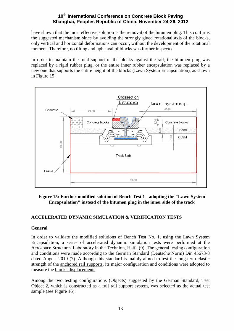
have shown that the most effective solution is the removal of the bitumen plug. This confirms the suggested mechanism since by avoiding the strongly glued rotational axis of the blocks, only vertical and horizontal deformations can occur, without the development of the rotational moment. Therefore, no tilting and upheaval of blocks was further inspected. In order to maintain the total support of the blocks against the rail, the bitumen plug was replaced by a rigid rubber plug, or the entire inner rubber encapsulation was replaced by a new one that supports the entire height of the blocks (Lawn System Encapsulation), as shown in Figure 15:
ACCELERATED DYNAMIC SIMULATION & VERIFICATION TESTS General In order to validate the modified solutions of Bench Test No. 1, using the Lawn System Encapsulation, a series of accelerated dynamic simulation tests were performed at the Aerospace Structures Laboratory in the Technion, Haifa (9). The general testing configuration and conditions were made according to the German Standard (Deutsche Norm) Din 45673-8 dated August 2010 (7). Although this standard is mainly aimed to test the long-term elastic strength of the anchored rail supports, its major configuration and conditions were adopted to measure the blocks displacements Among the two testing configurations (Objects) suggested by the German Standard, Test Object 2, which is constructed as a full rail support system, was selected as the actual test sample (see Figure 16):
Figure 15: Further modified solution of Bench Test 1 - adopting the "Lawn System Encapsulation" instead of the bitumen plug in the inner side of the track

10th International Conference on Concrete Block Paving Shanghai, Peoples Republic of China, November 24-26, 2012
14
The Actual Paved Test Sample (Object) and Loading Assembly Accordingly, the technical team of ASHTROM JLRT Design Department has designed and erected a prototype paved test sample (object) which simulates the actual Rail-Pavers supporting system applied in the JLRT line. It consists of metal confining frame, concrete track slab, anchored rail supports, rail, and paved area (CLSM, bedding sand and pavers). This prototype has been modified and improved during and after the two pilot tests, as will be described later. The rail was loaded at its thick upper part (under the train wheels), both vertically and also in variable inclined angles - for simulating the horizontal forces developed especially in curved tracks. Dimensional details of the paved test sample, the loading location and the tested area on the paver surface inside the track, are presented in Figure 17. The structure of the test sample (including frame, concrete slab and supported rail) was prepared at the JLRT workshop in Jerusalem. After concrete curing it was transported to the Technion in Haifa, were the final block paving was done before the dynamic loading tests. Five test samples have been prepared. Some of them were repaved for different paving patterns and loading configurations. Four variations of Block laying patterns and rail-paver systems were used:
1. Typical herringbone laying pattern and rail-paver system as used in the actual JLRT line (including the bitumen plug).
2. Typical herringbone laying pattern with the Lawn System Encapsulation. 3. "Piano" and "Brick" laying patterns with a glued rigid rubber strip replacing the
bitumen plug. 4. "Piano" 6 cm. thick blocks and "Herringbone" 8 cm. thick blocks laying pattern with
the Lawn System Encapsulation.
Figure 16: Configuration of "Test Object 2" according to the German Standard DIN 45673-8 (6)

10th International Conference on Concrete Block Paving Shanghai, Peoples Republic of China, November 24-26, 2012
15
Several dynamic test assemblies were developed and tried. After two pilot ones, the selected assembly is as follows: The test sample was placed horizontally on the solid floor under the loading-frame, loaded by variable inclined angles (19, 29 and 38.6 degrees), see Figure 18. It should be mentioned that the inclined angle of 38.6o is recommended in the DIN 45673-8 (Ref. 7) for simulating curved tracks.
Figure 17: Plan view and cross section of the paved test sample
Figure 18: Test sample placed horizontally on solid floor under the loading-frame, loaded by variable incline angles (19o in the picture)

10th International Conference on Concrete Block Paving Shanghai, Peoples Republic of China, November 24-26, 2012
16
Actual Dynamic Tests Performed Two pilot tests and six full actual dynamic tests, with the different test samples and loading assemblies, were performed at the Technion - Aerospace Structures Laboratory during the period between June 2011 and January 2012 (9,10). The tests were performed at frequencies ranged between 2-4 Hz. Table 1 summarizes the characteristics of each test:
Table 1: Characteristics of the dynamic tests performed
Test No.
Test Type
Loading Angle and max. force
Block Laying Pattern
Encap- sulation
Type
Bitumen Plug Remarks
I pilot 0o
(vertical) 5.2 tons
Regular 8 cm. Regular yes
Only after significant number of cycles (about 400,00) only minor tilt was observed (didn't simulate site tilting)
II pilot 38.6o
Inclined test sample 6.5 tons
Regular 8 cm.
regular yes The test was failed due to excessive
structure deformation and downward sand seepage in the inclined sample
IIIa actual 19o 5.5 tons
Regular 8 cm.
regular yes Same conditions for the variable inclined loading assembly and horizontal test sample
IIIb actual 29o 5.9 tons
Regular 8 cm.
regular yes
IIIc actual 38.6o 6.5 tons
Regular 8 cm.
regular yes
IV actual 29o 5.9 tons
Regular 8 cm. lawn removed Continuous vertical encapsulation
from bottom to top
V actual 38.6o 6.5 tons
Piano 8 cm.
with top rubber strip
removed The top rubber strip was glued to the rail and to the bottom encapsulation rubber but not to the blocks
VI actual 38.6o 6.5 tons
Piano 6 cm. Lawn removed Old laying pattern in Herzel Str. –
Piano 6 cm. and Herringbone 8 cm.
It should be noted that according to Din 45673-8 Standard (7), three millions loading cycles at maximum load, are specified to simulate 25-30 years of track service. Under this recommendation it was assessed that one million cycles will simulate 10 years of service of the JLRT. Also, as specified in that standard, the horizontal forces that arise when negotiating curved tracks are adequately simulated using a testing inclined angle of 38.6o. Deformations Measurement and Results In each test, static deformations (Horizontal and vertical) of the loaded rail, at the start and between loading cycles, were measured by LVDT's mounted on an isolated bridge. The accumulating values of lift-up or settlement deformations, developed in designated blocks

10th International Conference on Concrete Block Paving Shanghai, Peoples Republic of China, November 24-26, 2012
17
adjacent to the loading point, were continuously measured (at intervals) by a caliper at 0.1 mm accuracy. For each test, the most tilted and deformed block in the loading zone (the "critical block") was chosen to represent the dynamic fatigue behavior of the test sample under the specific condition of the test. Figure 19 summarizes the entire test program by presenting the lift-up deformation vs. number of loading cycles of the critical block in tests III through VI:
It should be mentioned that in Tests IV and V, in most of the blocks, a settlement in the order of few tenths of a millimeter was recorded instead of lift-up deformation. In Test V the small lift-up deformation in the "Piano" block was measured adjacent to the rail and not in the far side of the block, as usually occurred in Test series III with the bitumen plug. Also, in Test VI no lift-up deformation was observed in all measuring points in both sides of the rail. At the beginning of each test, a static load to its maximum magnitude was applied on the rail. Vertical and horizontal rail deformations were measured. For all six actual tests, the vertical static deformation ranged between 0.58-1.05 mm, while the horizontal deformations – between 0.63-2.15 mm. The higher static deformations occurred in the variations of test III. SUMMARY AND CONCLUSIONS Based on the extensive engineering and technological effort made by ASHTROM JLRT in analyzing the severe phenomenon of block tilting and lift-up during train movement
Figure 19: Summary of the entire test program by presenting the lift-up deformation vs. number of loading cycles of the critical block in tests III through VI:
0
2
4
6
8
10
12
1000 10000 100000 1000000
Test IIIa - Regular Laying, Bitumen, 19 Inclination
Test IIIb - Regular Laying, Bitumen, 29 Inclination
Test IIIc - Regular Laying, Bitumen, 38.6 Inclination
Test IV - Regular Laying, Lawn Encapsulation, 29
Test V -`Piano` Laying, Cover Strip Encapsulation, 38.6
Test VI -`Piano`6 cm Lawn, Encapsulation, 38.6
LIFT
-UP
DEFO
RMAT
ION
OF
CRIT
ICAL
BLO
CK (m
m)
LOADING CYCLES

10th International Conference on Concrete Block Paving Shanghai, Peoples Republic of China, November 24-26, 2012
18
(including many field trial, testing and measurements), a final dynamic simulation tests have been designed and performed at the Technion, Haifa. These tests were aimed to validate the suggested basic failure mechanism, and to predict the long-term fatigue behavior of the paving blocks with respect to the tilting and lift-up effect of recent selected solutions. The following is a set of conclusions and recommendations drawn so far: 1. The suggested block tilting mechanism is the basis of adopting Bench Test 1, which was
designed and tested in different versions. The essence of this Bench Test is the validated fact that the bitumen plug is the "Achilles Heel" of the rail-paver interface, and a major reason for the block tilting and lift-up. In all field experiments it was unequivocally proven that when the bitumen plug is just removed, or substituted by other material that does not bind the blocks to the rail, the sever tilting and lift-up is substantially restrained. The last version of Bench Test 1, with the installation of the Lawn System Encapsulation, or upper rigid rubber strip, was found to be the best solution since it both eliminates the rotational axis created by the bitumen plug bonding, and also provides an additional lateral and confining support for the blocks.
2. Generally, the accelerated dynamic tests performed at the Technion on realistic one-to-one scale test samples, were found to be a very powerful technological tool for assessing and predicting the block tilting and lift-up phenomenon under variable conditions associated with loading assembly, block laying pattern and rail-paver interface. Operating the dynamic loading cycles, at 2-4 Hz frequency for few days, can provide up to one million cycles, which is equivalent to about 10 years of train movement in the JLRT line.
3. The results of Test III series (control tests) provide a validation to the real behavior of the
paved track at the regular design conditions, including the bitumen plug. The rate of block tilting with time (about 8-10 millimeters lift-up after about 40,000 cycles (at 29-38.6o inclination) was quite similar to that occurred under real train movement between 4-5 months of train service, as seen in the following Figure 20. Also, by increasing the inclined angle of loading direction, the tilting rate intensified substantially. This simulates the same condition as occurred when decreasing the radius of curved tracks.
Figure 20: Tilting with lift-up deformation of inner blocks adjacent to the rail under
regular conditions with the bitumen plug (Test No. IIIc 38.6o inclination)

10th International Conference on Concrete Block Paving Shanghai, Peoples Republic of China, November 24-26, 2012
19
4. As also shown in Figure 19, a substantial difference does exist between the lift-up rate of the blocks measured in Test III, and that obtained in Tests IV through VI. It can be seen that even at the highest inclined loading direction (that simulate small radius curved tracks), very low lift-up deformations, in the order of 1 mm and down, was developed when the bitumen plug was replaced by a rigid rubber filler block. These very low lift-up deformations were kept constant up to about 1 million cycles of load application, that simulate about ten years of train service.
5. The results of Tests V and VI also demonstrate the structural soundness of the "Piano"
laying pattern (both in 6 and 8 cm. blocks) that was applied in the early stages of the JLRT construction in Herzl Street. A lift-up deformation up to 1 millimeter for a service life of about 10 years, indicates a long-term sustainability of the rail-paver system. This coincides with the actual current performance of the 6 cm "Piano" sections.
6. Accordingly, it can be concluded that the simulation dynamic tests, up to 1 million
cycles, produce a sound indication about the better solution for the long-term restraining of the tilting and lift-up deformation. Tests IV through VI demonstrated that the replacement of the bitumen plug by a rigid rubber filler block (either by the Lawn System Encapsulation or by the rubber strip) provide a sound long-term solution against the blocks tilting. It should be mentioned that the rubber strip solution strongly withstand the full term dynamic loading under the largest inclination angle of 38.6o and at 75 cm distance between the rail supports. It is therefore recommended to further try these two combinations of replacing the bitumen plug under real conditions in curved track sections along the JLRT line.
REFERENCES 1. Ishai, I., "Concrete Block Paving for the Swept Path in the Jerusalem Light Rail Transit
Project (JLRT) - Summary of Deign and Recommendations". Final Report, Prepared for ASHTROM, JLRT, Fourth Version, January 2009.
2. Ishai, I., Leviathan, E. and Liskevitch, G., "Application and Testing of Concrete Block Paving in Urban Light Rail Transit Lines", Proceedings, 9th International Conference on Concrete Block Paving, Buenos Aires, October 2009.
3. Israel Ministry of Housing and Construction – MHC, "Design Guidelines for Urban
Streets – Roads, Aprons and Sidewalk Pavements", Volume 3, August 2000. 4. Israel Standard Institute – ISI "Concrete Block Pavements", Israeli Standard I.S. 1571.
Approved 1998. 5. Israel Standard Institute – ISI "Prefabricated Concrete Products for Paving", Israeli
Standard I.S. 8. Approved 2000.
6. ISOTOP Ltd. "Measurement of Displacements and Strains during Train Movements in the Jerusalem Light Train Line". Final Report – Work No. GEF-09/10-2679. Prepared for ASHTROM, JLRT, December 2010.
7. German Standard (Deutsche Norm) "DIN 45673-8: "Mechanical Vibration – Resilient
Elements used in Railway Tracks – Part 8: Laboratory Test Procedures for continuous Elastic Rail supports" (English translation), August 2010.

10th International Conference on Concrete Block Paving Shanghai, Peoples Republic of China, November 24-26, 2012
20
8. Ishai, I., "Concrete Block Paving for the Swept Path in the Jerusalem Light Rail Transit Project, Blocks Tilting Adjacent to the Rails – Outcome and Implementation of Bench Tests No. 1 & 2 and Preliminary Recommendations for Application". Final Report, Prepared for ASHTROM, JLRT, March 2011.
9. Technion Faculty of Aerospace Engineering, Aerospace Structures Laboratory,
"Performance of Dynamic Tests on Part of a Rail + Paving" Prepared for Ashtrom –JLRT, September 2011.
10. Ishai, I. "Blocks Tilting Adjacent to the Rails in the JLRT Project – Summary of
Dynamic Simulation Tests for Predicting Fatigue Life of Selected Solutions for Rail-Pavers Systems", Final Report, February 2012.
ACKNOWLEDGEMENTS This paper was prepared within the framework of Pavement Consulting Services provided to Ashtrom JLRT and CityPass Consortium. The authors wish to thank these companies for their sponsorship and help in this challenging project. Acknowledgment is also due to Eng. Moshe Benjo for his daily assistance and support. The equipment and dynamic tests were installed and performed by the Aerospace Structures Laboratory, Faculty of Aerospace Engineering, Technion Haifa. Special thanks are rendered to Prof. Haim Abramovich and to Mr. Ariel Greenwald for the superb work.