Embed Size (px)
Citation preview

Lightning / Surge Protection for RadioRA® 2, HomeWorks® QS, and HomeWorks® Devices
Application Note #97Revision G
December 2014
1 Technical Support — 800.523.9466
Table of Contents
Overview ............................................................................................................................................ 2
Recommendations ............................................................................................................................ 3
Surge Protection Equipment ........................................................................................................... 4
Breaker Panel Protection ................................................................................................................. 4
RS-232 Protection ........................................................................................................................... 4
RS-485 Protection ........................................................................................................................... 5
H48/D48 Interface Protection (HomeWorks® QS and HomeWorks® only) ........................................ 5
Line Voltage Protection .................................................................................................................... 6
Breaker Panel Equipment Placement ............................................................................................... 6
Breaker Panel Wiring Detail ............................................................................................................. 6
Dimming Module Equipment Placement .......................................................................................... 7
Dimming Module Wiring Detail ......................................................................................................... 7
RadioRA® 2 ........................................................................................................................................ 8
RS-232 Equipment Placement .................................................................................................... 8, 9
RS-232 Component Wiring Detail ................................................................................................ 8, 9
RS-485 Equipment Placement ................................................................................................ 10, 11
RS-485 Component Wiring Detail ............................................................................................ 10, 11
HomeWorks® QS ............................................................................................................................. 12
RS-485 Equipment Placement. ............................................................................................... 12, 14
RS-485 Component Wiring Detail ............................................................................................ 13, 15
HomeWorks® ................................................................................................................................... 16
RS-232 Equipment Placement. ............................................................................................... 16, 17
RS-232 Component Wiring Detail ............................................................................................ 16, 17
RS-485 Equipment Placement ................................................................................................ 18, 20
RS-485 Component Wiring Detail ............................................................................................ 19, 20
H48/D48 Equipment Placement .............................................................................................. 21, 23
H48/D48 Component Wiring Detail.......................................................................................... 22, 24
Combination RS-485 and H48/D48 Component Wiring Detail ....................................................... 24
Lightning Strike Information .......................................................................................................... 25
Contact Information ....................................................................................................................... 26

2 www.lutron.com
Application Note #97
Overview
Lightning strikes may cause permanent damage to household electrical equipment, including LutronR System components. Lightning strike-damaged equipment is not covered by the LutronR Warranty and should be reported to the homeowner’s insurance company.
All LutronR products are designed with integrated surge suppression devices. (Lutron follows the IEEE C62.41-1991 recommended practice on Surge Voltages in Low Voltage AC Power Circuits.) These integrated suppression devices are effective for preventing damage in most installations. Despite this fact, high-risk homes that are located in lightning-prone locations may experience surge levels that are capable of damaging LutronR devices, particularly in the case of a direct lightning strike on the property. (For additional information on lightning-prone areas of the U.S. and abroad, see the maps at the end of this application note.) Although this type of damage is typically covered by the homeowner’s insurance, there is inconvenience involved in getting equipment replaced and / or having non-functional products. Many installers and homeowners are interested in adding additional protection hardware to their systems to minimize the risk of this sort of disruption. This application note was written to address these interests.
The devices recommended in this document are some of the most rugged and cost-effective protection devices available. Although installing these devices will provide an added degree of protection, in the most extreme circumstances damage is still a possibility. The likelihood of damage occurring will be greatly reduced when surge protection is used. This application note covers surge protection of low voltage links and the high voltage side of the installation with use of AC panel mount surge suppression with filtering. This may require additional solutions including: lightning rods, grounding methods, and local (near to a component) surge suppression, etc. High voltage surge suppression requires expertise (consider consultants if this is not internal to your organization) and up-front planning / design.
Our customers often ask why Lutron doesn’t integrate the surge protection provided by the external devices directly into our products. The primary reason is that over time (many surges) or given a surge with sufficient energy the suppression devices can / will fail. When they fail they tend to fail “shorted” to ground. This failure mode is “good” in the respect that it continues to protect the LutronR equipment, although communications on the link will no longer work. External surge protection devices can be replaced easily, at low cost, with no reprogramming. If the devices were built into the LutronR product, the entire product would have to be replaced. We may have delayed the product replacement but we haven’t prevented it.
Other benefits of external protection are:
• For maximum protection, it is best to have surge energy shunted away before it gets into the LutronR equipment
• The physical space required is impractical to implement in many products
• Not every customer needs to “pay” (in terms of size or cost) for this protection (for example, per the lightning strike maps, someone in the Northwest with a single building install, no integration connected,...)

3 www.lutron.com
Application Note #97
Recommendations
Installation Based Recommendations
• Protect all electrical breaker panels feeding dimmers, processors, and dimming panels. A panelmounted surge suppression unit with enhanced filtering will protect equipment from catastrophicevents, clean the power, and suppress internally generated transients that can lockup electronics,necessitate reprogramming of controls, and gradually deteriorate sensitive electronics. See Section3.4.3, IEEE Std.1100-2005.
• Protect all RS-232 ports with permanently connected third party equipment (typically otherprocessors that are part of integration systems). While RS-232 communication wire runs arethemselves short, all of the equipment and wire runs that are connected to the third-partyequipment provide an electrical path to conduct damaging surges. Damage most often occursbecause the ground referencing between the two systems can become separated during a surge.This creates high voltages that damage the RS-232 ports, and is the most common type of portfailure.
• Protect any link or bus that travels between buildings regardless of geographical location.Again damage may occur because the ground referencing between buildings can becomeseparated during a lightning strike. Lutron recommends using fiber optic communication betweenbuildings. Using fiber cable breaks the electrical connection (by using light rather than currentcarrying conductors) and will minimize damage if one building gets struck. Refer to “RS-485
Communication Using Fiber Optics Modem FAQ” on the HomeWorksR Resource Website.
• Protect Links/Busses that have wire runs over 500 ft (152.4 m) long even if they are containedwithin a single building. A long wire run is susceptible to high levels of capacitively coupledsurge energy as it travels alongside other wires and through the structure and mechanicals of thebuilding.
Geographical Based Recommendations
Refer to the lightning strike maps at the end of this document.
• Protect all breaker panels feeding lighting system from internal and external surges.
• Protect 120 V~ outputs from dimming modules which go outside (such as to landscape lighting)in areas that are determined to be at high risk, such as those at high elevations, and those in closeproximity to water.
• Protect all links / busses for installations in orange and red areas. In the US, for example, thiswould include Florida, the Southeast, and portions of the Midwest.
• Protect all links / busses for installations in areas that are determined to be at high risk, such asthose at high elevations, and those in close proximity to water.
Note: The lightning strike maps in this application note are best viewed in color. Please view on acomputer or print out in color.

4 www.lutron.com
Application Note #97
Surge Protection Equipment
The following surge protection equipment may be used to protect lighting panels and all dimming controls. The following suppression units will protect the electrical system from external transients entering the system through the power lines. The filtering part of the units will clean the power, and suppress internally generated transients that can lockup electronics, necessitate reprogramming of controls, and gradually deteriorate sensitive electronics. See Section 3.4.3, IEEE Std.1100-2005.
Breaker Panel Protection
1. Total Protection Solutions Breaker
Panel Protection
Manufacturer: Total Protection Solutions, LLC.Model Number: TK-TTLP-1S240-FLWebsite: www.TPSsurge.com
Photo
gra
ph c
ourt
esy o
f
Tota
l P
rote
ction S
olu
tions
RS-232 Surge Protection
The following surge protection equipment may be used to protect RS-232 ports
1. Total Protection Solutions RS-232
Surge Protection
Manufacturer: Total Protection Solutions, LLCModel Number: TK-CT2-DB9-DIN2Website: www.TPSsurge.com P
hoto
gra
ph c
ourt
esy o
f
Tota
l P
rote
ction S
olu
tions

5 www.lutron.com
Application Note #97
Surge Protection Equipment (continued)
RS-485 Protection
The surge protection equipment listed below may be used to protect the RS-485 links.
1. Total Protection Solutions RS-485Surge ProtectionManufacturer: Total Protection Solutions, LLC.Model Number: TK-CT2-24LIT24Model Number: TK-CT2-24LIT12Model Number: TK-CT2-24LIT4Website: www.TPSsurge.com
Note: 24-Terminal (12-pair), 12-terminal (6-pair), and 4-terminal (2-pair) devices are available. Choose model based on the
number of RS-485 links and H48/D48 dimming busses to be protected. Same unit can be used for both dimming busses and links.
Photo
gra
ph c
ourt
esy o
f
Tota
l P
rote
ction S
olu
tions
TK-CT2-24LIT24 (12 pair) TK-CT2-24LIT12 (6 pair) TK-CT2-24LIT4 (2 pair)
1. Total Protection Solutions H48 / D48 Surge ProtectionManufacturer: Total Protection Solutions, LLC.Model Number: TK-CT2-24LIT24Model Number: TK-CT2-24LIT12
Website: www.TPSsurge.comNote: 24-Terminal (12-pair) and 12-terminal (6-pair) devices
are available. Choose model based on the number of RS-485 links and H48/D48 dimming busses to be protected. Same unit can be used for both dimming busses and links.
Photo
gra
ph c
ourt
esy o
f
Tota
l P
rote
ction S
olu
tions
H48 / D48 dimming interface Protection (HomeWorksR and HomeWorksR QS only)
The surge protection equipment listed below may be used to protect the H48/D48 dimming interface.
TK-CT2-24LIT24 (12 pair) TK-CT2-24LIT12 (6 pair)

6 www.lutron.com
Application Note #97
Line Voltage Protection
Breaker Panel Equipment Placement – Using Total Protection Solutions
Example: Connection to breaker panel.
Locate and install one TK-TTLP-1S240-FL at each breaker panel feeding HomeworksR processors, dimming modules and remote module interface.
Remote Module Interface
Dimming Panel
HomeWorksR ProcessorTK-TTLP-1S240-FL
Power/ Breaker Panel
120 V~Circuits Protect Power to Equipment
Install white and green wires to the Neutral/ground bus
Install two black wires to a 2 Pole 20 A or 30 A Circuit Breaker
TK-TTLP-1S240-FL
120/240 V~ split phase breaker panel
Breaker Panel Wiring Detail – Using Total Protection Solutions Installation Based Recommendations
Install on all breaker panels powering LutronR equipment.

7 www.lutron.com
Application Note #97
Example: Connection to 120 V~ landscape lighting
Line Voltage Protection (continued)Dimming Module Equipment Placement – Using Total Protection Solutions
TK-LT120-20A-DIN2
Protect Dimming ModulesMay require an additional enclosure
to house surge protectionsTo landscape lighting.
Note: Surge suppressor must be grounded to a common point ground which is tied to the AC ground of the processor.
Dimming Module Wiring Detail – Using Total Protection Solutions
Total Protection Solutions Installation Based Recommendations
From DimmingModules
To LandscapeLighting
HotNeutralGround
HotNeutralGround
TK-LT120-20A-DIN2

8 www.lutron.com
Application Note #97
RadioRAR 2
RS-232 Equipment Placement – Using Total Protection Solutions
Example: Total Protection Solutions Model # TK-CT2-DB9-DIN2 Connection to Third Party RS-232 Equipment
Patch Cable
RadioRAR 2 Main Repeater
Patch Cable
RS-232 Cable
Third-party RS-232 Equipment
RS-232 Component Wiring Detail – Using Total Protection Solutions
Total Protection Solutions Model # TK-CT2-DB9-DIN2 with third-party RS-232 equipment
Total Protection SolutionsModel #TK-CT2-DB9-DIN2
Note: Surge suppressor must be grounded to a common point ground which is tied to the AC ground of the processor.
Note: An adapter cable is required. The length of the adapter cable depends on the enclosure being used and where the suppressor is being located.
Main Repeater
To third-party RS-232 Equipment
Integrate
RS232
Program/Integrate
Ethernet
TK-CT2-DB9-DIN2

9 www.lutron.com
Application Note #97
Setup
WiredRF
Communication
Repeater Status1 3 42 M
AddTest
USB
Integrate Program / Integrate
RS232 Ethernet
Main Repeater
Setup
WiredRF
Communication
Repeater Status1 3 42 M
Power Repeater LinkCO
M� �
1
� / C
MU
�
MU
�
2 3 4
AddTest
Auxiliary RepeaterSetup
WiredRFRFFFRFRFRFFRFRRF
Communication
eRRRepeaterpRRepRepepepeRReRepeeppeaRReeeeppppeeeeeppppeeppp Statusuussstuuusssuusssuuuss11 33 3 422MMMMMMMMM
AAAddddAAAAdddTTTeTeesstTTTT sstt
USB
Integrate Program / Integrate
RS232 Ethernet
Main RMainMainMain RMain RMain RMain Rain Rain RMain RMain RM iMain RMai RRRMainMMMainMMaaaaininnnMain RMain Rn RRRMainMMainaainn RRRMMain Raaiinnn RMain Ra eeepeateeeeeeee r
Setupppp
WiredRF
Communication
Repeater Status1 3 42M
PowerPPoower RRRepeater LRRR inkCO
MM�� ��
11
� / CC
MU
��
MU
��
222 333 444
AddddddTesTesttTeesstt
AuxiliAuxiliary Reary peatereaa
TK-CT2-24LIT24
Main Repeater
Wired Link
Auxiliary Repeater
RS-485 Equipment Placement – Using Total Protection Solutions
RadioRA® 2 (continued)
RS-485 Component Wiring Detail – Using Total Protection Solutions
_
Common
MUX
Earth ground¹
Field wiring
Wired Link
To a TK-CT2-24LIT24 or Auxillary Repeater
TK-CT2-24LIT24
+24V²
EQUI
P
CABL
E
1 2 3 4

10 www.lutron.com
Application Note #97
RS-485 Equipment Placement – Using Total Protection Solutions
Example: HomeWorks systems with low-voltage wire runs outside or between buildings using Total Protection Solutions
HomeWorks® QS (continued)
HomeWorksR QSProcessorTK-CT2-24LIT24
TK-CT2-24LIT24
QS Link
Hybrid Repeater
GRAFIC EyeR QS unit
TK-CT2-24LIT24
Keypad
Keypad
HomeWorksR QSProcessor
TK-CT2-24LIT4TK-CT2-24LIT24
Module InterfaceWiring distance greater
than 500 ft (152.4 m)
Example: System components that are wired greater than 500 ft (152.4 m) from the processor:
Protect Processor and Interface

11 www.lutron.com
Application Note #97
HomeWorks® QS (continued)
RS-485 Component Wiring Detail – Using Total Protection Solutions
Total Protection Solutions TK-CT2-24LIT24 with Inter-Processor Link, Module Interface Link, GRAFIK Eye® Link, Shade Interface or Dimmer Interface not powered by Processor
Earth Ground1
LutronR Processor
Link or Module
Interface
LutronR Processor
Link or Module
Interface
EQUI
P
CABL
E
EQUI
P
CABL
E
Common
MUX
N/C Field wiring
MUX
Common
MUX
+24 V2
MUX
To a TK-CT2-24LIT24, Keypads or Hybrid Repeaters
To a TK-CT2-24LIT24, or HomeWorksR Device
Field wiring
TK-CT2-24LIT24
TK-CT2-24LIT24
Earth Ground1
1 2 3 4
1 2 3 4Total Protection Solutions TK-CT2-24LIT24 with Keypad Link, Hybrid Repeater Link
NOTES:1 A good connection must be made between the TK-CT2-24LIT24 and earth
ground. This can be done with the terminal post on the top of the unit2 Connect +24 V terminal only if the keypads or Hybrid Repeater is being powered
form the link and not from an external power supply or local transformer.3 The TK-CT2-24LIT24, TK-CT2-24LIT12 and the TK-CT2-24LIT4 can be used on
both dimming busses and RS-485 links.
12 www.lutron.com
Application Note #97
Third-party RS-232 Equipment
RS-232 Cable
Protect Power to EquipmentHomeWorksR Processor
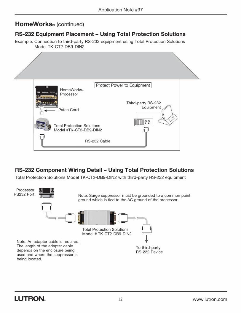
To third-party RS-232 Device
Total Protection Solutions Model # TK-CT2-DB9-DIN2
Note: Surge suppressor must be grounded to a common point ground which is tied to the AC ground of the processor.
Note: An adapter cable is required. The length of the adapter cable depends on the enclosure being used and where the suppressor is being located.
ProcessorRS232 Port
HomeWorks® (continued)
RS-232 Equipment Placement – Using Total Protection Solutions
Example: Connection to third-party RS-232 equipment using Total Protection Solutions Model TK-CT2-DB9-DIN2
RS-232 Component Wiring Detail – Using Total Protection Solutions
Total Protection Solutions Model TK-CT2-DB9-DIN2 with third-party RS-232 equipment
Patch Cord
Total Protection Solutions Model #TK-CT2-DB9-DIN2

13 www.lutron.com
Application Note #97
Keypad
HomeWorksR Processor
TK-CT2-24LIT4TK-CT2-24LIT24
Module InterfaceWiring distance greater
than 500 ft (152.4 m)
RS-485 Equipment Placement – Using Total Protection Solutions
Example: System components that are wired greater than 500 ft (152.4 m) from the processor:
HomeWorks® (continued)
Protect Processor and Interface
RS-485 Component Wiring Detail – Using Total Protection Solutions
Total Protection Solutions Model TK-CT2-24LIT24 with Inter-Processor Link, Module Interface Link, GRAFIK Eye® Link, Shade Interface, Dimmer Interface not powered by processor
Earth Ground1
LutronR Processor
Link or Module
Interface
LutronR Processor
Link or Module
Interface
EQUI
P
CABL
E
EQUI
P
CABL
E
Common
MUX
N/C Field wiring
MUX
Common
MUX
+24 V2
MUX
To a TK-CT2-24LIT24, Keypads or Hybrid Repeaters
To a TK-CT2-24LIT24, or HomeWorksR Device
Field wiring
TK-CT2-24LIT24
TK-CT2-24LIT24
Earth Ground1
1 2 3 4
1 2 3 4Total Protection Solutions Model TK-CT2-24LIT24 with Keypad Link, Hybrid Repeater Link
NOTES:1 A good connection must be made between the TK-CT2-24LIT24 and earth
ground. This can be done with the terminal post on the top of the unit2 Connect +15 V terminal only if the keypads or Hybrid Repeater is being powered
form the link and not from an external power supply or local transformer.3 The TK-CT2-24LIT24, TK-CT2-24LIT12 and the TK-CT2-24LIT4 can be used on
both dimming busses and RS-485 links.

14 www.lutron.com
Application Note #97
H48/D48 Equipment Placement – Using Total Protection Solutions
Example: HomeWorks systems with low-voltage wire runs outside or between buildings using Total Protection Solutions
HomeWorks® (continued)
Protect H48/D48 Dimmer Interface
HomeWorksR Processor
Wiring from H48/D48 to Dimmers
Wiring from H48/D48 to Dimmers
Main House
TK-CT2-24LIT24

15 www.lutron.com
Application Note #97
H48/D48 Component Wiring Detail – Using Total Protection Solutions
Total Protection Solutions Model TK-CT2-24LIT12 with H48 Dimmer Busses
H48 Dimmer Bus 1/2/3/4
Terminals
Total Protection Solutions Model TK-CT2-24LIT12 with Keypad Link, Hybrid Repeater Link
To Bus 1 DimmersTo Bus 2 Dimmers
To Bus 3 DimmersTo Bus 4 Dimmers
Earth
Ground
Earth Ground1
Maximum wire run distance is not affected by surge protection.EQ
UIP
CABL
E
To Bus 1 DimmersTo Bus 2 Dimmers
To Bus 3 DimmersTo Bus 4 Dimmers
TTTTTTTTTTTTTTTTTTTTTTTTTT
TTTTTTTTTTTTTTTTTTTTTTTTTTTTT
Earth
Ground
Earth Ground1
Maximum wire run distance is not affected by surge protection.EQ
UIP
CABL
E
H48 Dimmer Bus 1/2/3/4
Terminals
Notes: 1 A good connection must be made between the TK-CT2-24LIT12 and earth ground. This can be done with the terminal
post on the top of the unit. 2 To protect an entire H48 Interface use (1) TK-CT2-24LIT12 or use (1) TK-CT2-24LIT24 for both dimming busses and
RS-485 links.3 To protect an entire D48 Interface use (1) TK-CT2-24LIT24 or use (2) TK-CT2-24LIT12.4 The TK-CT2-24LIT24, TK-CT2-24LIT12 and the TK-CT2-24LIT4 can be used on both dimming busses and RS-485 links.
Combination RS-485 and H48/D48 Component Wiring Detail
Total Protection Solutions Model TK-CT2-24LIT24 with Inter-Processor Link, Module Interface Link, GRAFIK Eye® Link, Shade Interface, Dimmer Interface, Keypad Link & Hybrid Repeater Link
Note: The TK-CT2-24LIT24, TK-CT2-24LIT12 and the TK-CT2-24LIT4 can be used on both dimming busses and RS-485 links.
HomeWorks® (continued)

16 www.lutron.com
Application Note #97
Lightning Strike InformationLightning Protection Resources:National Lightning Safety Institute: www.lightningsafety.com | Lightning Protection Institute: www.lightning.org
Global lightning distribution map
U.S. lightning distribution map

Lutron Electronics Co., Inc.7200 Suter RoadCoopersburg, PA 18036-1299 U.S.A.P/N 048097 Rev. G 12/2014
Application Note #97
17
Contact Information
Total Protection Solutions, LLC Parts List Breaker Panel ProtectionTK-TTLP-1S240-FL Unlimited Amperage
Dimming Module ProtectionTK-LT120-20A-DIN2 Max 20 A CircuitTK-LT120-15A-DIN2 Max 15 A Circuit
RS232 ProtectionTK-CT2-DB9-DIN2 RS232 DB9 Connection
RS-485 & H48/D48 Dimmer Interface Protection
TK-CT2-24LIT24 24 Wire (12 pair)TK-CT2-24LIT12 12 Wire (6 pair)TK-CT2-24LIT4 4 Wire (2 pair)
Total Protection Solutions, LLCPO Box 3760Winter Park, FL 32790-3760Phone: +1.800.448.4087Fax: +1.407.951.5887Web: www.TPSsurge.comSales Email: [email protected] Support: [email protected]
Lutron Contact Numbers
Lutron, HomeWorks QS, HomeWorks, RadioRA are registered trademarks and RadioRA 2 is a trademark of Lutron Electronics Co., Inc.
WORLD HEADQUARTERS USA
Lutron Electronics Co., Inc. 7200 Suter Road Coopersburg, PA 18036-1299 TEL: +1.610.282.3800 FAX: +1.610.282.1243 Toll-Free: 1.888.LUTRON1 Technical Support: 1.800.523.9466
North & South America Technical Hotlines
USA, Canada, Caribbean: 1.800.523.9466 Mexico: +1.888.235.2910 Central/South America: +1.610.282.6701
EUROPEAN HEADQUARTERS United Kingdom
Lutron EA Ltd. 6 Sovereign Close London, E1W 3JF United Kingdom TEL: +44.(0)20.7702.0657 FAX: +44.(0)20.7480.6899 FREEPHONE (UK): 0800.282.107 Technical Support: +44.(0)20.7680.4481
ASIAN HEADQUARTERS Singapore
Lutron GL Ltd. 15 Hoe Chiang Road #07-03, Tower 15 Singapore 089316 TEL: +65.6220.4666 FAX: +65.6220.4333 Technical Support: 800.120.4491
Asia Technical HotlinesNorthern China: 10.800.712.1536 Southern China: 10.800.120.1536 Hong Kong: 800.901.849 Indonesia: 001.803.011.3994 Japan: +81.3.5575.8411 Macau: 0800.401 Taiwan: 00.801.137.737 Thailand: 001.800.120.665853 Other Countries: +65.6220.4666
Parts List