Embed Size (px)
Citation preview

Danfoss Scroll for Refrigeration MLM/MLZ116
50Hz - R404A - R22
Application guidelines
http://cc.danfoss.com


Content
Single compressors .............................................................................................................4
Manifold compressors .......................................................................................................39
3FRCC.PC.035.A5.02
Application Guidelines
Features ................................................................................................................................ 6
Scroll compression principle .............................................................................................. 7The scroll compression process.............................................................................................................................................................7
Compressor model designation ......................................................................................... 8Nomenclature ..............................................................................................................................................................................................8Label ................................................................................................................................................................................................................8Serial number...............................................................................................................................................................................................8
Technical specifications ...................................................................................................... 950 Hz ...............................................................................................................................................................................................................9
Dimensions ........................................................................................................................ 10MLM/MLZ116 ............................................................................................................................................................................................ 10Suction and discharge connections ................................................................................................................................................. 11
Electrical data, connections and wiring ........................................................................... 12Motor voltage ........................................................................................................................................................................................... 12Wiring connections ................................................................................................................................................................................. 12IP rating ....................................................................................................................................................................................................... 12Terminal box temperature ................................................................................................................................................................... 12Three phase electrical characteristics .............................................................................................................................................. 13Suggested wiring diagrams logic ...................................................................................................................................................... 15
Approvals and certifications ............................................................................................. 17Internal free volume ............................................................................................................................................................................... 17
Operating conditions ........................................................................................................ 18Refrigerant and lubricants.................................................................................................................................................................... 18Motor supply ............................................................................................................................................................................................. 19Compressor ambient temperature ................................................................................................................................................... 19Application envelope ............................................................................................................................................................................. 19Maximum discharge gas temperature ............................................................................................................................................ 21High and low pressure protection..................................................................................................................................................... 22On/off cycling (cycle rate limit) .......................................................................................................................................................... 22Defrost cycle .............................................................................................................................................................................................. 22
System design recommendations .................................................................................... 23General ........................................................................................................................................................................................................ 23Essential piping design considerations ........................................................................................................................................... 23Refrigerant charge limit ....................................................................................................................................................................... 24Off-cycle migration ................................................................................................................................................................................. 24Liquid flood back ..................................................................................................................................................................................... 26
Specific application recommendations ........................................................................... 27Low ambient application ...................................................................................................................................................................... 27Scroll and reciprocating ........................................................................................................................................................................ 27Low load operations ............................................................................................................................................................................... 28Brazed plate heat exchangers ............................................................................................................................................................. 28Water utilising systems .......................................................................................................................................................................... 28
Sound and vibration management .................................................................................. 29Starting sound level................................................................................................................................................................................ 29Running sound level .............................................................................................................................................................................. 29Stopping sound level ............................................................................................................................................................................. 29Sound generation in a refrigeration system .................................................................................................................................. 29Compressor sound radiation ............................................................................................................................................................... 29Mechanical vibrations ............................................................................................................................................................................ 30Gas pulsation ............................................................................................................................................................................................ 30
Content
4 FRCC.PC.035.A5.02
Application Guidelines Single compressors

Installation ......................................................................................................................... 31System cleanliness .................................................................................................................................................................................. 31Compressor handling and storage.................................................................................................................................................... 31Compressor mounting .......................................................................................................................................................................... 32Compressor holding charge ................................................................................................................................................................ 32Tube brazing procedure ........................................................................................................................................................................ 32Brazing material ....................................................................................................................................................................................... 32Vacuum evacuation and moisture removal ................................................................................................................................... 33Liquid line filter driers ............................................................................................................................................................................ 33Refrigerant charging .............................................................................................................................................................................. 34Insulation resistance and dielectric strength ................................................................................................................................ 34
Ordering information and packaging .............................................................................. 35Packaging ................................................................................................................................................................................................... 35Packaging details ..................................................................................................................................................................................... 35Industrial pack .......................................................................................................................................................................................... 35
Spare parts & accessories .................................................................................................. 36
Content
5FRCC.PC.035.A5.02
Application Guidelines Single compressors

Features
With its unique scroll design and manufacturing process flexibility, the new Danfoss scroll for refrigeration, MLZ/MLM116 offers a highly efficient solution for demanding refrigeration applications.
This new medium-temperature scroll compressor is designed for commercial refrigeration applications and extends Danfoss’ refrigeration compressors to 26.8 kW (15 HP) at common voltage and with a common refrigerant (R404A-R22).
Thanks to its dedicated refrigeration design, the MLZ/MLM scroll compressor delivers a number of powerful advantages. With its high-efficiency motor and optimized scroll design, it reduces
energy cost in normal operating conditions and delivers high capacity and an optimized pressure ratio for refrigeration applications.
6 FRCC.PC.035.A5.02
Application Guidelines Single compressors
Scroll compression principle
Danfoss scroll compressors are manufactured using the most advanced machining, assembly and process control techniques. In the design of both the compressor and the factory, very
high standards of reliability and process control were first priority. The result is a highly efficient product with the highest reliability obtainable, and a low sound level.
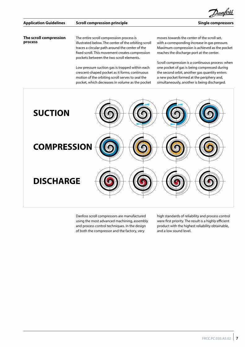
The entire scroll compression process is illustrated below. The center of the orbiting scroll traces a circular path around the center of the fixed scroll. This movement creates compression pockets between the two scroll elements.
Low pressure suction gas is trapped within each crescent-shaped pocket as it forms; continuous motion of the orbiting scroll serves to seal the pocket, which decreases in volume as the pocket
moves towards the center of the scroll set, with a corresponding increase in gas pressure. Maximum compression is achieved as the pocket reaches the discharge port at the center.
Scroll compression is a continuous process: when one pocket of gas is being compressed during the second orbit, another gas quantity enters a new pocket formed at the periphery and, simultaneously, another is being discharged.
The scroll compression process
SUCTION
COMPRESSION
DISCHARGE
7FRCC.PC.035.A5.02
Application Guidelines Single compressors

Compressor model designation
Label
Serial number
Nomenclature
Type FeaturesMotorSize
M LZ C 5T 4 B116Application
M: medium temperature refrigeration
Family, Refrigerant & lubricantLZ: R404A, PVE lubricant (160HV)LM: R22, mineral lubricant
Nominal capacityIn thousand Btu/h at 60 Hz,ARI, MBP conditions
Model variationT: design optimized for refrigeration
Motor protectionB: Electronic, 230 V
Tubing and electrical connectionsC: brazed connections, screw terminalsQ: rotolock connections, screw terminals
Motor voltage code4: 380-415 V/3 ph/50 Hz
Other features
Oil sight glass
Oil equali-zation
Oil drain
LP gauge port
Gas equali-zation port
5 Threaded Schrader Schrader NoneThreaded
A 1234567825 B
Plant assembly line code
Month code
Year code8 digit serial number
8 FRCC.PC.035.A5.02
Application Guidelines Single compressors

Technical specifications
50 Hz
Model HP
Nominalcooling capacity
Powerinput
EfficiencySwept volume Displacement Oil charge Net weight
(with oil)COP EER
W Btu/h kW W/W Btu/h/W cm3/rev m3/h Litres kg
MLM116 15 24451 83427 10789 2.27 7.73 249.9 43.5 6.7 100
MLZ116 15 26865 91664 12127 2.22 7.56 249.9 43.5 6.7 100
Note: EN12900 conditions: To= -10°C, Tc= 45°C, RGT= 20°C, SC= 0K
9FRCC.PC.035.A5.02
Application Guidelines Single compressors

Dimensions
MLM/MLZ116
Grommet
All dimensions in mm
Terminal box
Refer to section “Ordering information and packaging” for overview of shipped mounting accessories
Ø 266
Ø 257.4
Discharge1"1/8
Suction1"5/8
652617
188
214
301.5
531±1.2
92.576.6
Ø 318
4x Ø 19.43
(29.5)/Without compression
(28.0)/With compression
Oil sight glass
345
195
171
428
212
371304.8
181
279.4
60°
90°
90°
30°
Discharge1"1/8
Ø 266
Ø 257.4Suction1"5/8
188617
652
214
301.5
76.6
Ø 318(29.5)/Without compression
(28.0)/With compression
531±1.2
345
279.4
183
157
4x Ø 19.43
30°
428
212
90°
371
304.8
60°181
Black Blue Brown
Faston 1/4" tabs
Power supply
Sump heater
Modulepower supply
M1-M2control circuit
HM 8 boltLock washer
Flat washer
Steel mounting sleeve
Rubber grommet
Nut
28 mm
Compressorbase plate
Rotolock connection-MLZ/MLM116 T4QC5Brazed connection-MLZ/MLM116 T4BC5
10 FRCC.PC.035.A5.02
Application Guidelines Single compressors

Dimensions
MLZ/MLM scroll compressors could deliver either braze connection or rotolock connections.
Dedicated Rotolock adaptors and adaptor sets are available as accessories.
Suction and discharge connections
Compressor models
Brazed version Rotolock version
Connection sizeRotolock adaptor set
(Adaptor, Gasket, Sleeve, Nut)Rotolock adaptor(Adaptor only)
Rotolock Solder sleeve ODF Code Number Code Number
MLM/MLZ116Suction 1"5/8 2"1/4 1”5/8
7765028120Z0432
Discharge 1"1/8 1"3/4 1"1/8 120Z0364
Connection detailsMLM/MLZ116
Suction and discharge connections Brazed / Rotolock
Oil sight glass Threaded
Oil equalization connection Rotolock 2"1/4
Oil drain connection 1/4’’ flare
Low pressure gauge port (Schrader) 1/4’’ flare
Oil drain connection
Oil sight glass Danfoss MLZ/MLM116 scroll compressors come equipped with a sight glass (1"1/8 - 18 UNF) which may be used to determine the amount and condition of the oil contained within the sump.
The oil fill connection and gauge port is a 1/4" male flare connector incorporating a Schrader valve.
MLM/MLZ116: 2”1/4 Rotolock connector allowing the use of 2”1/4 - 1”3/8. This connection must be used to mount an oil equalization line when two compressors are mounted in parallel.
The oil drain connection allows oil to be removed from the sump for changing, testing, etc. The fitting contains an extension tube into the oil sump to more effectively remove the oil. The connection is a female 1/4" flare fitting incorporating a Schrader valve and is mounted on MLM/MLZ116 models.
Schrader
Oil equalization connection
Oil fill connection and gauge port
Oil drain connection
11FRCC.PC.035.A5.02
Application Guidelines Single compressors

Electrical data, connections and wiring
MLZ/MLZ116 compressors are available only in code 4.Motor voltage
The compressor terminal box according to IEC529 is IP54 for all models when correctly sized IP54 rated cable glands are used.
First numeral, level of protection against contact and foreign objects5 - Dust protectedSecond numeral, level of protection against water4 - Protection against water splashing
The temperature inside the terminal box may not exceed 70°C. Consequently, if the compressor is installed in an enclosure, precautions must be taken to avoid the temperature around the compressor and in the terminal box from rising too much. The installation of ventilation on the enclosure panels may be necessary. If not, the
electronic protection module may not operate properly. Any compressor damage related to this will not be covered by the Danfoss warranty. In the same manner, cables must be selected in a way to ensure that terminal box temperature does not exceed 70°C.
IP rating
Terminal box temperature
Electrical power is connected to the compressor terminals by Ø 4.8 mm (3/16”) screws.
The maximum tightening torque is 3 Nm. Use a 1/4’’ ring terminal on the power leads.
Wiring connections
Motor voltage code 4
Nominal voltage 50 Hz 380-415 - 3ph
Voltage range 50 Hz 340-457 V
The terminal box is provided with 2 triple knockouts and 1 single knockout for power supply and 4 double knockouts for the safety control circuit.
The 3 power supply knockouts accommodate the following diameters:• Ø 50.8 mm (UL 1"1/2 conduit) and Ø 43.7
mm (UL 1"1/4 conduit) and Ø 34.5 mm (UL 1" conduit)
• Ø 40.5 mm (ISO40) and Ø 32.2 mm (ISO32) and Ø 25.5 mm (ISO25)
• Ø 25.5 mm (ISO25)
The 4 others knockouts are as follows:• Ø 22.5 mm (PG16) (UL 1/2") and Ø 16.5 mm
(ISO16) (x2) • 20.7 mm (ISO20 or PG13.5) (x2)
MLM/MLZ116
Black Blue Brown
Faston 1/4" tabs
Power supply
Sump heater
Modulepower supply
M1-M2control circuit
The motor protection module comes preinstalled within the terminal box. Phase sequence protection connections and thermistor connections are pre-wired. The module must be connected to a power supply of the appropriate voltage. The module terminals are 6.3 mm size Faston type.
L N S1 S2 M1 M2
L1 L2 L3Black Blue Brown
Phase sequence input
Internal control contact
SafetycircuitThermistor
connectionModule power
L N M1 M2
Note: please make sure M1/M2 is connected to OEM controller and L/N is connected to outside power supply, otherwise, there will be no motor protection.
12 FRCC.PC.035.A5.02
Application Guidelines Single compressors

Electrical data, connections and wiring
Three phase electrical characteristics
Compressor model LRA MCC Max. operating current Winding resistanceA A A Ω
Motor voltage code 4 380-415 V/3 ph/50 Hz MLZ/MLM116 175 39 35 0.914
Locked Rotor Amp value is the higher average current as measured on mechanically blocked compressor tested under nominal voltage. The LRA value can be used as rough estimation for
the starting current. However in most cases, the real starting current will be lower. A soft starter can be applied to reduce starting current.
LRA (Locked rotor amp)
The MCC is the current at which the motor protection trips under maximum load and low voltage conditions. This MCC value is the maximum at which the compressor can be
operated in transient conditions and out of the application envelope. Above this value, the electronic module will cut out the compressor to protect the motor.
MCC (Maximum continuous current)
The max. operating current is the current when the compressor operates at maximum load conditions and 10% below nominal voltage. Max Oper. A can be used to select cables and contactors.
In normal operation, the compressor current consumption is always less than the Max Oper. A. value.
Max. operating current
Winding resistance is the resistance between phases at 25°C (resistance value +/- 7%).Winding resistance is generally low and it requires adapted tools for precise measurement. Use a digital ohm meter, a "4 wires" method and measure under stabilized ambient temperature. Winding resistance varies strongly with winding temperature. If the compressor is stabilized at a different value than 25°C, the measured resistance must be corrected using following formula:
a + tamb
Rtamb = R25°C _______ a + t25°C
t25°C : reference temperature = 25°Ctamb: temperature during measurement (°C)R25°C: winding resistance at 25°CRamb: winding resistance at tambCoefficient a = 234.5
Winding resistance
The inrush current for the Danfoss MLM/MLM116 compressors with motor code 4 380-415 V/3 ph/50 Hz can be reduced using the Danfoss soft starter. MCI soft starters are designed to reduce the starting current of
3-phase AC motors; they can reduce the inrush current by up to 40%, thereby eliminating the detrimental effects of high-starting torque surges and costly demand charges from the resultant current spike.
Danfoss MCI soft-start controller
Upon starting, the controller gradually increases the voltage supplied to the motor until full-line voltage has been reached.
For MCI50M, all settings such as initial torque, ramp-up time (less than 0.5 sec) and ramp-down time are preset and do not require any modification.
Initial torque
ramp-upramp-down
Time
U
Compressor model Soft start referenceAmbient max. 40°C
Soft start referenceAmbient max. 55°C
MLM/MLZ116 MCI50CM MCI50CM ** by-pass contactor K1 is required
13FRCC.PC.035.A5.02
Application Guidelines Single compressors

Electrical data, connections and wiring
When the control voltage is applied to A1 - A2, the MCI soft starter will start the motor, according to the settings of the ramp-up time and initial torque adjustments. When the control voltage is switched off, the motor will switch off instantaneously.
Input controlled soft start
By means of the built-in auxiliary contact (23-24) the by pass function is easily achieved, see wiring diagram opposite.
No heat is generated from the MCI. As the contactor always switches in no-load condition it can be selected on the basis of the thermal current (AC-1).
MCI with by pass contactor
General wiring information
The wiring diagrams below are examples for safe and reliable compressor wiring. In case an alternative wiring logic is chosen, it is imperative to respect the following rules:
When a safety switch trips, the compressor must stop immediately and must not re-start until the tripping condition is back to normal and the safety switch is closed again. This applies to the LP safety switch, the HP safety switch, the discharge gas thermostat and the motor safety thermostat.
In specific situations, such as winter start operation, an eventual LP control for pump-down cycles may be temporarily bypassed to
allow the system to build pressure. But it remains mandatory for compressor protection to apply an LP safety switch. The LP safety switch must never be bypassed.
Pressure settings for the LP and HP safety switch and pump-down listed in table from section "Low pressure".
When ever possible (i.e. PLC control), it is recommended to limit the possibilities of compressor auto restart to less than 3 to 5 times during a period of 12 hours when caused by motor protection or LP safety switch tripping. This control must be managed as a manual reset device.
14 FRCC.PC.035.A5.02
Application Guidelines Single compressors

Electrical data, connections and wiring
Fuses ..................................................................................................F1Compressor contactor ................................................................. KMControl relay ................................................................................... KASafety lock out relay .......................................................................KSOptional short cycle timer (3 mins) ......................................180 sExternal overload protection .......................................................F2Pump-down pressure switch .......................................................LPHigh-pressure safety switch ........................................................HPControl device ................................................................................. TH
Liquid line solenoid valve ........................................................ LLSVDischarge gas thermostat/thermistor................................... DGTFused disconnect ...........................................................................Q1Motor safety thermostat ............................................................thMCompressor motor ..........................................................................MMotor protection module ........................................................MPMThermistor chain............................................................................... SSafety pressure switch .................................................................LPS
Legend
MLM/MLZ116
A1
A3
A2
MPM
S
LPS
Wiring diagram with pump-down cycle
LP
A1A3
A2
MPM
SKS
Wiring diagram without pump-down cycle
LPS
Suggested wiring diagrams logic
Motor protection
Compressor model Overheating protection
Over current protection
Locked rotor protection Phase reversal protection
MLM/MLZ116 Electronic module located in terminal box
Compressor models MLM/MLZ116 are delivered with a pre-installed motor protection module inside the terminal box. This device provides for efficient and reliable protection against overheating/overloading/phase loss/reversal.
The motor protector comprises a control module and PTC sensors embedded in the motor winding. The close contact between thermistors and windings ensures a very low level of thermal inertia.
The motor temperature is being constantly measured by a PTC thermistor loop connected on S1-S2. If any thermistor exceeds its response temperature, its resistance increases above the trip level (4,500 Ω) and the output relay then trips – i.e. contacts M1-M2 are open. After cooling to below the response temperature (resistance < 2,750 Ω), a 5-minute time delay is activated.
After this delay has elapsed, the relay is once again pulled in – i.e. contacts M1-M2 are closed. The time delay may be cancelled by means of resetting the mains (L-N -disconnect) for approximately 5 sec.
A red/green twin LED is visible on the module. A solid green LED denotes a fault-free condition. A blinking red LED indicates an identifiable fault condition:
PTC overheat
Appr. 1 second
Delay timer active (after PTC over temp.)
Appr. 1 second
15FRCC.PC.035.A5.02
Application Guidelines Single compressors

Electrical data, connections and wiring
Use a phase meter to establish the phase orders and connect line phases L1, L2 and L3 to terminals T1, T2 and T3, respectively. The compressor will only operate properly in a single
direction, and the motor is wound so that if the connections are correct, the rotation will also be correct.
Phase sequence and reverse rotation protection
The lockout may be cancelled by resetting the power mains (disconnect L-N) for approximately 5 seconds.
Compressor models MLM/MLZ116 are delivered with an electronic module which provides protection against phase reversal and phase loss at start-up. Apply the recommended wiring diagrams from section "Suggested wiring diagram logic". The circuit should be thoroughly checked in order to determine the cause of the phase problem before re energizing the control circuit.
The phase sequencing and phase loss monitoring functions are active during a 5-sec window 1 second after compressor start-up (power on L1-L2-L3).
Compressor
start
Phase monitoring 0 1 s 6 s
Phase sequence module logic
Should one of these parameters be incorrect, the relay would lock out (contact M1-M2 open). The red led on the module will show the following blink code:
In case of phase reverse error:
Appr. 1 second
In case of phase loss error:
Appr. 1 second
Vavg = Mean voltage of phases 1, 2, 3.
V1-2 = Voltage between phases 1 and 2.
V1-3 = Voltage between phases 1 and 3.
V2-3 = Voltage between phases 2 and 3.
| Vavg - V1-2 | + | Vavg - V1-3 | + | Vavg - V2-3 |
2 x Vavg% voltage imbalance = x 100
The operating voltage limits are shown in the table section "Motor voltage". The voltage applied to the motor terminals must lie within these table limits during both start-up and normal operations. The maximum allowable voltage
imbalance is 2%. Voltage imbalance causes high amperage over one or several phases, which in turn leads to overheating and possible motor damage. Voltage imbalance is given by the formula:
Voltage imbalance
16 FRCC.PC.035.A5.02
Application Guidelines Single compressors

Approvals and certifications
Internal free volumeProducts Internal free volume at LP side without oil (liter) Internal free volume at LP side with oil (liter)
MLM/MLZ116 28.8 22.1
17FRCC.PC.035.A5.02
Application Guidelines Single compressors

Operating conditions
The scroll compressor application range is influenced by several parameters which need to be monitored for a safe and reliable operation.These parameters and the main recommendations for good practice and safety devices are explained hereunder.
• Refrigerant and lubricants• Motor supply• Compressor ambient temperature• Application envelope (evaporating
temperature, condensing temperature, return gas temperature)
General information
Refrigerant and lubricants
When choosing a refrigerant, different aspects must be taken into consideration:• Legislation (now and in the future)• Safety• Application envelope in relation to expected
running conditions• Compressor capacity and efficiency• Compressor manufacturer recommendations &
guidelines
Additional points could influence the final choice:• Environmental considerations• Standardization of refrigerants and lubricants• Refrigerant cost• Refrigerant availability
R22 R22 is an HCFC refrigerant and is still a wide use today. It has a low ODP (Ozone depletion potential) and therefore it will be phased out in the future. Check local legislation.
When R22 is applied in refrigeration applications it can lead to high discharge temperature. Carefully check all other parameters that can influence the discharge temperature.
R404A
PVE
R404A is an HFC refrigerant. R404A has zero ozone depletion potential (ODP = 0). R404A is especially suitable for low evaporating temperature applications but it can also be applied to medium evaporating temperature applications. R404A is a mixture and has a very
small temperature glide, and therefore must be charged in its liquid phase, but for most other aspects this small glide can be neglected. Because of the small glide, R404A is often called a near-azeotropic mixture.
Polyvinyl ether (PVE) is an innovative refrigeration lubricant for HFC refrigerant systems. PVE is as hygroscopic as existing polyolester lubricants (POE), but PVE doesn’t chemically react with water; no acids are formed and compressor evacuation is easier.
The compressor technology applied in MLZ compressors in combination with PVE lubricant provides the best possible result in terms of reliability and compressor lifetime.
Mineral oil Mineral oil can be applied in system using HCFC refrigerant because it has a good miscibility with HCFC and oil that leave the compressor with refrigerant may not be trapped in lines or
exchangers. The chlorine contained in HCFCs improves lubricity in bearings used with mineral oil. Mineral oil has a very low hygroscopicity but may chemically react with water and form acids.
18 FRCC.PC.035.A5.02
Application Guidelines Single compressors

Operating conditions
Motor supply MLZ/MLM scroll compressors can be operated at nominal voltages as indicated in the table in the section “Motor voltage”. Under-voltage and over-voltage operation is allowed within the indicated
voltage ranges. In case of risk of under-voltage operation, special attention must be paid to current draw.
The operating envelopes for MLZ/MLM scroll compressors are given in the figures below, where the condensing and evaporating temperatures represent the range for steady-state operation. Under transient conditions, such as start-up and defrost, the compressor may operate outside this envelope for short periods.
The figures below show the operating envelopes for MLZ/MLM compressors with refrigerants R404A and R22. The operating limits serve
to define the envelope within which reliable operations of the compressor are guaranteed:• Maximum discharge gas temperature: +135°C.• Minimum suction superheat should be above
5 K due to the risk of liquid flood-back.• Attention to suction line insulation to reduce
unuseful superheat.• Minimum and maximum evaporating and
condensing temperatures as per the operating envelopes.
MLZ/MLM compressors can be applied from -35°C to 55°C ambient temperature. The compressors are designed as 100% suction gas
cooled without need for additional fan cooling. Ambient temperature has very little effect on the compressor performance.
In case of enclosed fitting and high ambient temperature it’s recommend to check the temperature of power wires and conformity to their insulation specification.
In case of safe tripping by the internal compressor overload protection the compressor must cool down to about 60°C before the overload will reset. A high ambient temperature can strongly delay this cool-down process.
Although the compressor itself can withstand low ambient temperature, the system may require specific design features to ensure safe
and reliable operation. See section ‘Specific application recommendations’.
Application envelope
Compressor ambient temperature
High ambient temperature
Low ambient temperature
MLZ116 - R404A
RGT: +20°C
Superheat: 10 K
Cond
ensi
ng te
mpe
ratu
re (°
C)
Evaporating temperature (°C)
-35 -30 -25 -20 -15 -10 -5 0 5 10 15
5
10
15
20
25
30
35
40
45
50
55
60
65
19FRCC.PC.035.A5.02
Application Guidelines Single compressors

Operating conditions
RGT: 20°C
Superheat: 10 K
MLM 116 - R22
10
15
20
25
30
35
40
45
50
55
60
65
70
75
-35 -30 -25 -20 -15 -10 -5 0 5 10 15 20
Evaporating temperature (°C)
Con
dens
ing
tem
pera
ture
(°C
)
20 FRCC.PC.035.A5.02
Application Guidelines Single compressors

Operating conditions
Discharge gas temperature protection (DGT)
DGT protection is required if the high and low pressure switch settings do not protect the compressor against operations beyond its specific application envelope. Please refer to the examples below, which illustrate where DGT protection is required (n°1) and where it is not (n°2).
The compressor must not be allowed to cycle on the discharge gas thermostat. Continuous operations beyond the compressor’s operating range will cause serious damage to the compressor!
A DGT accessory is available from Danfoss: refer to section “Spare parts & accessories”.
The discharge temperature depends mainly on the combination of evaporating temperature, condensing temperature and suction gas superheat. Discharge gas temperature should be controlled with an isolated thermocouple or
thermostat attached to the discharge line 15 cm (6 inches) from the compressor shell. Maximum discharge gas temperature must not exceed 135°C (275°F) when the compressor is running within the approved operating envelope.
Maximum discharge gas temperature
MLZ116
RGT: +20°C Example 2
Example 1
Superheat: 10 K
Cond
ensi
ng te
mpe
ratu
re (°
C)
Evaporating temperature (°C)
-35 -30 -25 -20 -15 -10 -5 0 5 10 15
5
10
15
20
25
30
35
40
45
50
55
60
65
HP1
HP2
LP1 LP2
Example 1 (R22, SH = 10 K) LP switch setting: LP1 = 1 bar (g) (-25°C) HP switch setting: HP1 = 21.8 bar (g) (58°C) The LP and HP switches don't protect sufficiently from opera-tion outside the envelope. A DGT protection is required to avoid operation in the hatched area.
Example 2 (R22, SH = 10 K) LP switch setting: LP2 = 2.5 bar (g) (-10°C) HP switch setting: HP2 = 18 bar (g) (49°C) The LP and HP switches protect from operation outside the envelope. No DGT protection required.
Discharge line
Insulation
Bracket
Thermostat
21FRCC.PC.035.A5.02
Application Guidelines Single compressors

Operating conditions
A low pressure (LP) safety switch is recommended. MLZ/MLM scroll compressors exhibit high volumetric efficiency and may draw very low vacuum levels, which could induce scroll instability and electrical arcing at the internal cluster. The minimum low-pressure safety switch setting is given in the above table. For systems
without pump-down, the LP safety switch must either be a manual lockout device or an automatic switch wired into an electrical lockout circuit. The LP switch tolerance must not allow for vacuum operations of the compressor. LP switch settings for pump-down cycles with automatic reset are also listed in the table above.
Low pressure
On/off cycling (cycle rate limit)
Depending on the application, a number higher than 12 starts per hour can reduce the service life of the motor-compressor unit. A one-minute time out is recommended.
The system must be designed in a way that provides a minimum compressor running time
of 3 minutes so as to provide for sufficient motor cooling after start-up along with proper oil return. Note that the oil return may vary since it depends upon system design.
Danfoss recommends a restart delay timer to limit compressor cycling.
R22 R404A
Working pressure range high side bar (g) 7.1 - 26 9.9 - 27.7
Working pressure range low side bar (g) 0.7 - 6.2 1.0 - 6.6
Maximum high pressure safety switch setting bar (g) 27.1 29
Minimum low pressure safety switch setting bar (g) 0.5 0.7
Recommended pump-down switch settings 1.5 bar below nominal evaporating pressure
Minimum low pressure pump-down switch setting bar (g) 0.6 0.9
LP safety switch shall never have time delay.
For MLZ/MLZ116, a high pressure switch is required to shut down the compressor should the discharge pressure exceed the values shown in the table above.
The high-pressure switch can be set to lower values depending on the application and
ambient conditions. The HP switch must either be placed in a lockout circuit or consist of a manual reset device to prevent cycling around the high-pressure limit. If a discharge valve is used, the HP switch must be connected to the service valve gauge port, which must not be isolated.
High pressure
High and low pressure protection
Defrost cycle In refrigeration system applications, there are different defrost methods, such as electric heating defrost, hot gas bypass defrost, reversible defrost etc. For the system which use hot gas bypass or reversible defrost method, suction accumulator is necessary as a result of the possibility of a substantial quantity of liquid refrigerant remaining in the evaporator,
this liquid refrigerant can then return to the compressor, either flooding the sump or as a dynamic liquid slug when the cycle switch back to normal cooling operations. Sustained and repeated liquid slugging and flooding can seriously impair the oil’s ability to lubricate the compressor bearings. In such cases a suction accumulator is a must.
22 FRCC.PC.035.A5.02
Application Guidelines Single compressors
System design recommendations
Essential piping design considerations
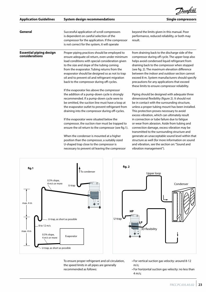
Proper piping practices should be employed to ensure adequate oil return, even under minimum load conditions with special consideration given to the size and slope of the tubing coming from the evaporator. Tubing returns from the evaporator should be designed so as not to trap oil and to prevent oil and refrigerant migration back to the compressor during off-cycles.
If the evaporator lies above the compressor the addition of a pump-down cycle is strongly recommended. If a pump-down cycle were to be omitted, the suction line must have a loop at the evaporator outlet to prevent refrigerant from draining into the compressor during off-cycles.
If the evaporator were situated below the compressor, the suction riser must be trapped to ensure the oil return to the compressor (see fig.1).
When the condenser is mounted at a higher position than the compressor, a suitably sized U-shaped trap close to the compressor is necessary to prevent oil leaving the compressor
from draining back to the discharge side of the compressor during off cycle. The upper loop also helps avoid condensed liquid refrigerant from draining back to the compressor when stopped (see fig. 2). The maximum elevation difference between the indoor and outdoor section cannot exceed 8 m. System manufacturers should specify precautions for any applications that exceed these limits to ensure compressor reliability.
Piping should be designed with adequate three dimensional flexibility (figure 2). It should not be in contact with the surrounding structure, unless a proper tubing mount has been installed. This protection proves necessary to avoid excess vibration, which can ultimately result in connection or tube failure due to fatigue or wear from abrasion. Aside from tubing and connection damage, excess vibration may be transmitted to the surrounding structure and generate an unacceptable sound level within that structure as well (for more information on sound and vibration, see the section on: “Sound and vibration management”).
General Successful application of scroll compressors is dependent on careful selection of the compressor for the application. If the compressor is not correct for the system, it will operate
beyond the limits given in this manual. Poor performance, reduced reliability, or both may result.
0.5% slope,4 m/s or more
0.5% slope,4 m/s or more
U-trap
U-trap, as short as possible
U-trap, as short as possible
max. 4 m
�g.1
max. 4 m
8 to 12 m/s
To condenser
Evaporator
Condenser
HP
U-trap
3D flexibility
Upper loop
LP
fig. 2
To ensure proper refrigerant and oil circulation, the speed limits in all pipes are generally recommended as follows:
• For vertical suction gas velocity: around 8-12 m/s;
• For horizontal suction gas velocity: no less than 4 m/s;
23FRCC.PC.035.A5.02
Application Guidelines Single compressors

System design recommendations
Refrigerant charge limit MLZ/MLM scroll compressors can tolerate liquid refrigerant up to a certain extend without major problems. However, excessive liquid refrigerant in the compressor is always unfavorable for service life. Besides, the installation cooling capacity may be reduced because of the evaporation taking place in the compressor and/or the suction line instead of the evaporator. System design must be such that the amount of liquid refrigerant in the compressor is limited. In this respect, follow the guidelines given in the section: “essential piping
design recommendations” in priority.Use the tables below to quickly evaluate the required compressor protection in relation with the system charge and the application. More detailed information can be found in the paragraphs hereafter. If refrigerant charge exceeds the limit, a liquid receiver and suction accumulator will be essential to ensure that the system runs reliably. Please contact Danfoss for any deviation from these guidelines.
Model Refrigerant charge limit (kg)MLM/MLZ116 13.5
Off-cycle migration Off-cycle refrigerant migration is likely to occur when the compressor is located at the coldest part of the installation, when the system uses a bleed-type expansion device, or if liquid could migrate from the evaporator into the compressor sump by gravity. If too much liquid refrigerant accumulates in the sump it will saturate the oil and lead to a flooded start: when the compressor starts, the refrigerant evaporates abruptly
under the sudden decrease of the bottom shell pressure, causing the oil to foam. In extreme situations, this might result in too much oil leaving the compressor, which must be avoided as it causes irreversible damages due to possible lack of lubrication. MLZ/MLM scroll compressors can tolerate occasional flooded starts as long as the system has been evaluated.
A suitable test to evaluate the risk of off-cycle migration is the following:• Stabilize the non-running system at 5°C
ambient temperature.• Raise the ambient temperature to 20°C and
maintain it for 10 minutes.• Start the compressor and monitor sump
temperature, sight glass indication and sound level.
The presence of liquid in the crankcase can be easily detected by checking the sump level through the oil sight glass. Foam in the oil sump indicates a flooded start.A noisy start, oil loss from the sump and sump cool down are indications for migration. Depending on the amount of migration graduate measures shall be taken:• Sump heater• Liquid line solenoid valve• Pump down cycle (mandatory for
refrigeration application)
Note: for special conditions such as low ambient temperature, low load operation or brazed plate heat exchangers please refer to corresponding sections
Recommended Required No test or additional safeties requiredREQREC
BELOW charge limit ABOVE charge limit
Packaged units No test or additional safeties requiredOff cycle migration test
Liquid flood back test
System with remote heat exchanger Off cycle migration testOff cycle migration test Liquid flood back test
RECREQ
REQREQ
REQ
Depending on test results, crankcase heaters, Liquid Line Solenoid Valve, pump down or suction accumulator must be applied see below.
Sump heater The surface sump heaters are designed to protect the compressor against off-cycle migration of refrigerant.
When the compressor is idle, the oil temperature in the sump of the compressor must be maintained at no lower than 10 K above the saturation temperature of the refrigerant on the low-pressure side. This requirement ensures that the liquid refrigerant is not accumulating in the sump. A sump heater is only effective if capable
of sustaining this level of temperature difference. Tests must be conducted to ensure that the appropriate oil temperature is maintained under all ambient conditions (temperature and wind). Note that below -5°C ambient temperature and a wind speed of above 5 m/second, we recommend that the heaters be thermally insulated in order to limit the surrounding energy losses. Since the total system charge may be undefined, a sump heater is recommended on all stand-alone compressors and split systems.
24 FRCC.PC.035.A5.02
Application Guidelines Single compressors

System design recommendations
Pump-down cycle: Once the system has reached its set point and is about to shut off, the LLSV on the liquid line closes. The compressor then pumps the majority of the refrigerant charge into the high pressure side before the system stops on the low pressure pump-down switch. This step reduces the amount of charge on the low side in order to prevent off-cycle migration.
A pump-down cycle represents one of the most effective ways to protect against the off-cycle migration of refrigerant; however it is only convenient to apply on application with thermostatic control.
For MLM/MLZ116, pump down cycle is mandatory to use.
Rack application with pressostatic control can use timer delay to empty the evaporators before the stop. Time should be carefully set to not interfere with the low safety pressure switch.
For low pressure pump-down switch settings, refer to section "High and low pressure protection". For suggested wiring diagrams, please see section "Electrical data".
Under certain conditions, the internal valve may not completely seal, and due to the refrigerant back flow the compressor might restart during pump-down applications. Repeated short cycling can result in a compressor breakdown.
Tests for pump down cycle approval:• As the pump-down switch setting is inside the
application envelope, tests should be carried out to check unexpected cut-out during transient conditions (i.e. defrost – cold starting). When unwanted cut-outs occur, the low pressure pump-down switch can be delayed. In this case a low pressure safety switch without any delay timer is mandatory.
• While the thermostat is off, the number of pressure switch resets should be limited to avoid short cycling of the compressor. Use dedicated wiring and an additional relay which allows for one shot pump-down.
The pump-down allows stroage of all the refrigerant in the high pressure side circuit. On unitary or close-coupled systems, where the system refrigerant charge is expected to be both correct and definable the entire system charge
Liquid line solenoid valve (LLSV): This feature is very convenient and can be used on all types of applications.An LLSV is used to isolate the liquid charge in the high pressure side, thereby preventing against
charge transfer or excessive migration to the compressor during off-cycles. The quantity of refrigerant remaining in the low-pressure side of the system can be further reduced by using a pump-down cycle in association with the LLSV.
In addition, any system containing a refrigerant charge in excess of the maximum recommended system charge for compressors requires a sump heater.
At initial start-up or after power shortage, it is recommended to energize surface sump heater to remove refrigerant 6 hours in advance. A quicker start-up is possible by "jogging" the compressor to evacuate refrigerant in the compressor. Start the compressor for 1 second, then wait for 1 to 2 minutes. This operation must be repeated for each compressor individually:
Compressor 1
Compressor 2
Compressor 3
After 3 or 4 jogs the compressor can be started.
The heater must be energized whenever the compressor is off to avoid liquid refrigerant entering the compressor.
Provide separate electrical supply for the heaters so that they remain energized even when the machine is out of service (e.g. seasonal shutdown).Surface sump heater accessories are available from Danfoss (see section "Accessories").
on
off
on
off
on
off
25FRCC.PC.035.A5.02
Application Guidelines Single compressors

System design recommendations
Suction accumulator: a suction accumulator offers protection against refrigerant flood back at start-up, during operations or defrosting by trapping the liquid refrigerant upstream from the compressor. The suction accumulator also protects against off-cycle migration by providing additional internal free volume to the low side of the system. For MLZ/MLM116 application, suction accumulator is mandatory to use.
A suction accumulator must be carefully dimensioned, taking into account the refrigerant charge as well as the gas velocity in the suction line. Depending on the operating conditions it may happen that the recommended connections of the accumulator are one size smaller than the suction line.
Selection of a suction line accumulator should be made on the basis of the following three capabilities:
1. The accumulator should have an adequate liquid-holding capacity that can vary with the system. Normally this should not be less than 50% of the system charge. If possible, this value should be checked based on actual tests.2. The accumulator should perform without adding excessive pressure drop to the system.3. An accumulator should have the capability of returning oil at the proper rate and under a range of load conditions.
Guideline of suction accumulator needs to be respected in making a selection.
Liquid flood back During normal operation, refrigerant enters the compressor as a superheated vapor. Liquid flood back occurs when a part of the refrigerant entering the compressor is still in liquid state.
A continuous liquid flood back will cause oil dilution and, in extreme situations lead to lack of lubrication and high rate of oil leaving the compressor.
Liquid flood back test - Repetitive liquid flood back testing must be carried out under TXV threshold operating conditions: a high pressure ratio and minimum evaporator load, along with the measurement of suction superheat, oil sump temperature and discharge gas temperature.
During operations, liquid flood back may be detected by measuring either the oil sump temperature or the discharge gas temperature. If at any time during operations, the oil sump temperature drops to within 10 K or less above the saturated suction temperature, or should
the discharge gas temperature be less than 35 K above the saturated discharge temperature, this indicates liquid flood back.
Continuous liquid flood back can occur with a wrong dimensioning, a wrong setting or malfunction of the expansion device or in case of evaporator fan failure or blocked air filters.
A suction accumulator providing additional protection as explained hereunder can be used to solve light continuous liquid flood back.
may be stored in the condenser during pump-down if all components have been properly sized.
Other application needs a liquid receiver to store the refrigerant.
Receiver dimensioning requires special attention. The receiver shall be large enough to contain part of the system refrigerant charge but it shall not be dimensioned too large. A large receiver easily leads to refrigerant overcharging during maintenance operation.
26 FRCC.PC.035.A5.02
Application Guidelines Single compressors

Specific application recommendations
Low ambient application
Low ambient operations It is recommended that the unit be tested and monitored at minimum load and low ambient conditions as well. The following considerations should be taken into account to ensure proper system operating characteristics.
The expansion device should be sized to ensure proper control of the refrigerant flow into the evaporator. An oversized valve may result in erratic control. This consideration is especially important in manifolded units where low load conditions may require the frequent cycling of compressors. This can lead to liquid refrigerant entering the compressor if the expansion valve does not provide stable refrigerant super-heat control under varying loads.
The superheat setting of the expansion device should be sufficient to ensure proper superheat levels during low loading periods. A minimum of 5 K stable superheat is required.
Head pressure control under low ambient conditions: Several possible solutions are available to prevent the risk of compressor to vacuum and low pressure differential between the suction and discharge pressures.
In air-cooled machines, cycling the fans with a head pressure controller will ensure that the fans remain off until the condensing pressure has reached a satisfactory level. Variable speed fans can also be used to control the condensing pressure. In water-cooled units, the same can be performed using a water regulator valve that is also operated by head pressure, thereby ensuring that the water valve does not open until the condensing pressure reaches a satisfactory level.The minimum condensing pressure must be set at the minimum saturated condensing temperature shown in the application envelopes.
Under very low ambient conditions, in which testing has revealed that the above procedures might not ensure satisfactory condensing and suction pressures, the use of a head pressure control valve is recommended. Note: This solution requires extra refrigerant charge, which can introduce other problems. A non-return valve in the discharge line is recommended and special care should be taken when designing the discharge line.
For further information, please contact Danfoss.
Low ambient start-up Under cold ambient conditions (<0°C), upon start-up the pressure in the condenser may be so low that a sufficient pressure differential across the expansion device cannot be developed to properly feed the evaporator.
As a result, the compressor may go into a deep vacuum, which can lead to compressor failure due to internal arcing and instability in the scroll wraps. Under no circumstances should the compressor be allowed to operate under vacuum. The low-pressure control must be set in accordance with the table in the section ”high and low pressure protection” in order to prevent this from happening.
Early feeding of the evaporator and management of the discharge pressure could help to attenuate these effects.
Low pressure differentials can also cause the expansion device to “hunt” erratically, which might cause surging conditions within the evaporator, with liquid spillover into the compressor. This effect is most pronounced during low load conditions, which frequently occur during low ambient conditions.
Unlike the reciprocating compressor, a scroll doesn’t have dead volume. Neither does it have a suction valve causing pressure drop. As a result a scroll compressor has a high volumetric efficiency even at low suction pressure. In systems such as ice makers and milk cooling tanks this high capacity at low temperature shortens the cooling time.
When moving from a reciprocating compressor to a scroll compressor, the selection shall always be made based on cooling capacity at the application rating point. Never make a selection based on equivalent displacement.
Scroll and reciprocating
27FRCC.PC.035.A5.02
Application Guidelines Single compressors

Specific application recommendations
Low load operations The compressor should be run for a minimum period to ensure that the oil has sufficient time to properly return to the compressor sump and
that the motor receives enough cooling under conditions of lowest refrigerant mass flow.
Brazed plate heat exchangers
A brazed plate heat exchanger needs very little internal volume to satisfy the heat transfer requirements. Consequently, the heat exchanger offers very little internal volume for the compressor to draw vapor from the suction side. The compressor can then quickly enter into a vacuum condition. It is therefore important that the expansion device be sized correctly and that a sufficient pressure differential across the expansion device be available to ensure adequate refrigerant feed into the evaporator. This aspect is of special concern when operating the unit under low ambient and load conditions. For further information on these conditions, please refer to the previous sections.
Due to the small volume of the brazed plate heat exchanger, no pump-down cycle is normally required. The suction line running from the heat exchanger to the compressor must be trapped to avoid refrigerant migration to the compressor.
When using a brazed plate condenser heat exchanger, a sufficient free volume for the discharge gas to accumulate is required in order to avoid excess pressure build-up. At least 1 meter of discharge line is necessary to generate this volume. To help reduce the discharge gas volume immediately after start-up, the supply of cooling water to the heat exchanger may be opened before the compressor starts, to remove superheat and condense the incoming discharge gas more quickly.
Water utilising systems Apart from residual moisture in the system after commissioning, water could also enter the refrigeration circuit during operation. Water in the system shall always be avoided. Not only because it can shortly lead to electrical failure, sludge in sump and corrosion but in particular because it can cause serious safety risks.
Common causes for water leaks are corrosion and freezing.
Corrosion: Materials in the system shall be compliant with water and protected against corrosion.
Freezing: When water freezes into ice its volume expands which can damage heat exchanger walls and cause leaks. During off periods water inside heat exchangers could start freezing when ambient temperature is lower than 0°C. During on periods ice banking could occur when the circuit is running continuously at too low load. Both situations should be avoided by connecting a pressure and thermostat switch in the safety line.
28 FRCC.PC.035.A5.02
Application Guidelines Single compressors

Sound and vibration management
Running sound level
Stopping sound level
Sound generation in a refrigeration system
Compressor sound radiation
MLZ/MLM are designed with features to reduce the sound level when a compressor is running.
Sound levels are at rated (medium temperature) conditions.
MLZ/MLM have a unique discharge valve design that minimizes stopping noise. This results in very low shutdown sound.
Typical sound and vibration in refrigeration systems encountered by design and service engineers may be broken down into the following three source categories.Sound radiation: This generally takes an airborne path.
Mechanical vibrations: These generally extend along the parts of the unit and structure.Gas pulsation: This tends to travel through the cooling medium, i.e. the refrigerant.
The following sections will focus on the causes and methods of mitigation for each of the above sources.
For sound radiating from the compressor, the emission path is airborne and the sound waves are travelling directly from the machine in all directions.
The MLZ/MLM scroll compressors are designed to be quiet and the frequency of the sound generated is pushed into the higher ranges, which not only are easier to reduce but also do not generate the penetrating power of lower frequency sound.
Use of sound-insulation materials on the inside of unit panels is an effective means of substantially reducing the sound being transmitted to the outside. Ensure that no components capable of transmitting sound/vibration within the unit come into direct contact with any non insulated parts on the walls of the unit.Because of the unique design of a full-suction gas & oil cooled motor, compressor body insulation across its entire operating range is possible.
During start-up transients it is natural for the compressor sound level to be slightly higher than during normal running. MLZ/MLM scroll compressors exhibit very little increased start-up transient sound. If a 3-phase model is miswired, the compressor will run in reverse. Reverse
compressor rotation is characterized by an objectionable sound. To correct reverse rotation, disconnect power and switch any two of the three power leads at the unit contactor. Never switch leads at the compressor terminals.
Starting sound level
Model50 Hz
Sound power (dBA)
MLM116 82
MLZ116 84
29FRCC.PC.035.A5.02
Application Guidelines Single compressors
Sound and vibration management
Mechanical vibrations Vibration isolation constitutes the primary method for controlling structural vibration. MLZ/MLM scroll compressors are designed to produce minimal vibration during operations. The use of rubber isolators on the compressor base plate or on the frame of a manifolded unit is very effective in reducing vibration being transmitted from the compressor(s) to the unit. Rubber grommets are supplied with all MLZ/MLM compressors. Once the supplied rubber grommets have been properly mounted, vibration transmitted from the compressor base plate to the unit are held to a strict minimum.
In addition, it is extremely important that the frame supporting the mounted compressor be of sufficient mass and stiffness to help dampen any residual vibration potentially transmitted to the frame. The tubing should be designed so as to both reduce the transmission of vibrations to other structures and withstand vibration without incurring any damage. Tubing should also be designed for three-dimensional flexibility. For more information on piping design, please see the section entitled "Essential piping design considerations".
Gas pulsation The MLZ/MLM scroll compressors have been designed and tested to ensure that gas pulsation has been minimized for the most commonly encountered refrigeration pressure ratio. On installations where the pressure ratio lies beyond the typical range, testing should be conducted under all expected conditions and operating
configurations to ensure that minimum gas pulsation is present. If an unacceptable level is identified, a discharge muffler with the appropriate resonant volume and mass should be installed. This information can be obtained from the component manufacturer.
30 FRCC.PC.035.A5.02
Application Guidelines Single compressors

Installation
Each MLZ/MLM compressor is shipped with printed Instructions for installation. These Instructions can also be downloaded from our web site
www.danfoss.com or directly from:http://instructions.cc.danfoss.com
Compressor handling and storage
System cleanliness The refrigeration system, regardless of the type of compressor used, will only provide high efficiency and good reliability, along with a long operating life, if the system contains solely the refrigerant and oil it was designed for. Any other substances within the system will not improve performance and, in most cases, will be highly detrimental to system operations.
The presence of non-condensable substances and system contaminants, such as metal shavings, solder and flux, have a negative impact on compressor service life. Many of these contaminants are small enough to pass through a
mesh screen and can cause considerable damage within a bearing assembly. The use of highly hygroscopic PVE oil in MLZ compressors requires that the oil be exposed to the atmosphere just as little as possible.
During the manufacturing process, circuit contamination may be caused by:• Brazing and welding oxides,• Filings and particles from the removal of burrs in pipe-work,• Brazing flux,• Moisture and air.
Each Danfoss MLM/MLZ116 scroll compressor is equipped with two lift rings on the top shell. Always use both these rings when lifting the compressor. Use lifting equipment rated and certified for the weight of the compressor. A spreader bar rated for the weight of the compressor is highly recommended to ensure a better load distribution. The use of lifting hooks closed with a clasp and certified to lift the weight of the compressor is also highly recommended. Always respect the appropriate rules concerning lifting objects of the type and weight of these compressors. Maintain the compressor in an upright position during all handling manoeuvres (maximum of 15° from vertical).
Never use only one lifting lug to lift the compressor. The compressor is too heavy for the single lug to handle, and the risk is run that the lug could separate from the compressor with extensive damage and possible personal injury as a result.
Store the compressor not exposed to rain, corrosive or flammable atmosphere and between -35°C and 50°C when charged with nitrogen.
When the compressor is mounted as part of an installation, never use the lift rings on the compressor to lift the installation. The risk is run that the lugs could separate from the compressor or that the compressor could separate from the base frame with extensive damage and possible personal injury as a result.
Never apply force to the terminal box with the intention of moving the compressor, as the force placed upon the terminal box can cause extensive damage to both the box and the components contained inside.
HEAVY
do not liftmanually
31FRCC.PC.035.A5.02
Application Guidelines Single compressors

Installation
Compressor holding charge
Compressor mounting Maximum inclination from the vertical plane, while operating must not exceed 7 degrees. All compressors are delivered with 4 rubber grommets and metal sleeves. Compressors
must always be mounted with these grommets. Recommended torque for mounting bolts: 21 Nm (±1 Nm).
Brazing material For copper suction and discharge fittings, use copper-phosphorus brazing material. Sil-Fos® and other silver brazing materials are also acceptable.
If flux is required for the brazing operation, use coated rod or flux core wire. To avoid system contamination, do not brush flux on.
Tube brazing procedure Do not bend the compressor discharge or suction lines or force system piping into the compressor connections, because this will increase
stresses that are a potential cause of failure. Recommended brazing procedures and material, are described on following page.
Each compressor is shipped with a nominal dry nitrogen holding charge between 0.3 and 0.7 bar and is sealed with elastomer plugs.
Before the suction and discharge plugs are removed, the nitrogen holding charge must be released via the suction Schrader valve to avoid an oil mist blowout. Remove the suction plug
first and the discharge plug afterwards. The plugs shall be removed only just before connecting the compressor to the installation in order to avoid moisture from entering the compressor. When the plugs are removed, it is essential to keep the compressor in an upright position so as to avoid oil spillage.
Compressor connection When brazing the compressor fittings, do not overheat the compressor shell, which could severely damage certain internal components due to excessive heating. Use of a heat shield and/or a heat-absorbent compound is highly recommended. For brazing the suction and discharge connections, the following procedure is advised:
• Make sure that no electrical wiring is connected to the compressor.• Protect the terminal box and compressor painted surfaces from torch heat damage (see diagram).• Use only clean refrigeration-grade copper tubing and clean all connections.• Purge nitrogen through the compressor in order to prevent against oxidation and flammable conditions. The compressor should not be exposed to the open air for extended periods.• Use of a double-tipped torch is recommended.• Apply heat evenly to area A until the brazing temperature is reached. Move the torch to area B and apply heat evenly until the brazing temperature has been reached there as well, and then begin adding the brazing material. Move the torch evenly around the joint, in applying only enough brazing material to flow the full circumference of the joint.• Move the torch to area C only long enough to draw the brazing material into the joint, but not into the compressor.• Remove all remaining flux once the joint has been soldered with a wire brush or a wet cloth. Remaining flux would cause corrosion of the tubing.
Ensure that no flux is allowed to enter into the tubing or compressor. Flux is acidic and can cause substantial damage to the internal parts of the system and compressor.
The PVE oil used in MLZ compressors is highly hygroscopic and will rapidly absorb moisture from the air. The compressor must therefore not be left open to the atmosphere for a long period of time. The compressor fitting plugs shall be removed just before brazing the compressor.
! Before eventual unbrazing the compressor or any system component, the refrigerant charge must be removed from both the high and low pressure sides. Failure to do so may result in serious personal injury. Pressure gauges must be used to ensure all pressures are at atmospheric level.
For more detailed information on the appropriate materials required for brazing or soldering, please contact the product manufacturer or distributor. For specific applications not covered herein, please contact Danfoss for further information.
Heat shield
C B A
32 FRCC.PC.035.A5.02
Application Guidelines Single compressors
Installation
Moisture obstructs the proper functioning of the compressor and the refrigeration system.
Air and moisture reduce service life and increase condensing pressure, and cause excessively high discharge temperatures, which can destroy the lubricating properties of the oil. Air and moisture also increase the risk of acid formation, giving rise to copper platting. All these phenomena can cause mechanical and electrical compressor failure.
For these reasons it’s important to perform a vacuum dehydration on the system to remove all residual moisture from the pipe-work after assembly;
MLZ and MLM compressors are delivered with < 100 ppm moisture level. The required moisture level in the circuit after vacuum dehydration must be < 100 ppm for systems with an MLZ and < 300 ppm for systems with an MLM compressor.
• Never use the compressor to evacuate the system.
• Connect a vacuum pump to both the LP & HP sides.
• Evacuate the system to a pressure of 500 μm Hg (0.67 mbar) absolute.
• Do not use a megohmmeter nor apply power to the compressor while it’s under vacuum as this may cause internal damage.
Vacuum evacuation and moisture removal
Liquid line filter driers The proper size & type of drier is required. Important selection criteria include the driers water content capacity, the system refrigeration capacity, and the system refrigerant charge. The drier must be able to reach and maintain a moisture level of 50 ppm end point dryness (EPD). Danfoss recommends DCL (solid core) driers for the MLM compressor (R22 with mineral oil) and DML (100% molecular sieve) driers for MLZ compressors (R404A,) with PVE oil.
For servicing of existing installations where acid formation may be present, the Danfoss DCL solid core filter drier containing activated alumina is recommended.
After burn out, remove & replace the liquid line filter drier and install a Danfoss type DAS burnout drier of the appropriate capacity. Refer to the DAS drier instructions and technical information for correct use of the burnout drier on the liquid line.
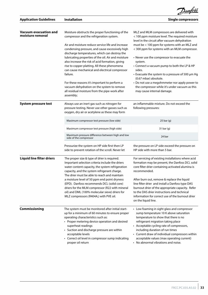
System pressure test Always use an inert gas such as nitrogen for pressure testing. Never use other gasses such as oxygen, dry air or acetylene as these may form
an inflammable mixture. Do not exceed the following pressures:
Maximum compressor test pressure (low side) 25 bar (g)
Maximum compressor test pressure (high side) 31 bar (g)
Maximum pressure difference between high and low side of the compressor 24 bar
Pressurize the system on HP side first then LP side to prevent rotation of the scroll. Never let
the pressure on LP side exceed the pressure on HP side with more than 5 bar.
The system must be monitored after initial start-up for a minimum of 60 minutes to ensure proper operating characteristics such as:• Proper metering device operation and desired
superheat readings• Suction and discharge pressure are within
acceptable levels• Correct oil level in compressor sump indicating
proper oil return
• Low foaming in sight glass and compressor sump temperature 10 K above saturation temperature to show that there is no refrigerant migration taking place
• Acceptable cycling rate of compressors, including duration of run times
• Current draw of individual compressors within acceptable values (max operating current)
• No abnormal vibrations and noise.
Commissioning
33FRCC.PC.035.A5.02
Application Guidelines Single compressors

Installation
Refrigerant charging It is recommended that system charging be done using the weighed charge method, adding refrigerant to the high side of the system. Charging the high and low sides of a system with gas simultaneously at a controlled rate is also an acceptable method. Do not exceed the recommended unit charge, and never charge liquid to the low side.
Vacuum or charge from one side can seal the scrolls and result in a non-starting compressor. When servicing, always ensure that LP/HP pressures are balanced before starting the compressor.
Be sure to follow all government regulations regarding refrigerant reclamation and storage.
Insulation resistance and dielectric strength
Insulation resistance must be higher than 1 megohm when measured with a 500 volt direct current megohm tester.
Each compressor motor is tested at the factory with a high potential voltage (hi-pot) that exceeds the UL requirement both in potential and in duration. Leakage current is less than 5 mA.
MLZ/MLM scroll compressors are configured with the pump assembly at the top of the shell, and the motor below. As a result, the motor can be partially immersed in refrigerant and oil. The presence of refrigerant around the motor windings will result in lower resistance
values to ground and higher leakage current readings. Such readings do not indicate a faulty compressor, and should not be cause for concern.
In testing insulation resistance, Danfoss recommends that the system be first operated briefly to distribute refrigerant throughout the system. Following this brief operation, retest the compressor for insulation resistance or current leakage.
Never reset a breaker or replace a fuse without first checking for a ground fault (a short circuit to ground). Be alert for sounds of arcing inside the compressor.
In installations with good oil return and line runs up to 10 m, no additional oil is required. If installation lines exceed 10 m, additional oil may be needed. 3 or 4% of the total system refrigerant charge (in weight) can be used to roughly define the required oil top-up quantity but in any case the oil charge has to be adjusted based on the oil level in the compressor sight glass. When the compressor is running under stabilized conditions the oil level must be visible in the sight glass.
The oil level can also be checked a few minutes after the compressor stops.When the compressor is off, the level in the
sight glass can be influenced by the presence of refrigerant in the oil.Top-up the oil while the compressor is idle. Use the Schrader connector or any other accessible connector on the compressor suction line and a suitable pump. See News bulletin "Lubricants filling in instructions for Danfoss Commercial Compressors".
MLZ116 is factory charged with PVE32, when topping up the compressor, customer could also use PVE68 lubricant. Danfoss supply PVE68 as accessory. There will be no reliability risks even MLZ116 is with 100% PVE68.
Oil level checking and top-up
34 FRCC.PC.035.A5.02
Application Guidelines Single compressors

Ordering information and packaging
Industrial pack Compressors are not packed individually but are shipped all together on one pallet. They can be ordered in quantities of full pallets only, multiples of 6 compressors, according below table.
Each industrial pack pallet contains following accessories:
• 4 grommets per compressor• 4 sleeves per compressor
Packaging
Packaging details
Compressors MLZ116/MLM116
Pack type Industrial pack
Compressors per pallet 6
Static stacking of pallets ** 2
Ship
ped
acce
ssor
ies 4 bolts per compressor Included
4 washers per compressor Included
4 grommets per compressor Included
4 extra sleeves per compressor Included
Additional accessories for rotolock version: 2 gasket Included
Industrial pack
Compressors Model variation Connections Features Voltage code 4
Danfoss pallet
MLM116 B C 5 120H1118
MLM116 B Q 5 120H1231
MLZ116 B C 5 120H1117
MLZ116 B Q 5 120H1230
35FRCC.PC.035.A5.02
Application Guidelines Single compressors

Spare parts & accessories
Solder sleeve adapter set
Type Code n° Description Application Packaging Pack size
7765028 Rotolock adaptor set (2"1/4 ~ 1"5/8) , (1"3/4 ~ 1"1/8) MLM/MLZ116 Multipack 6
* diameter restriction
Rotolock adapter
Type Code n° Description Application Packaging Pack size
120Z0432 Adaptor (2"1/4 Rotolock - 1"5/8 ODS) Models with 1"5/8 ODF Multipack 10
120Z0364 Adaptor (1"3/4 Rotolock - 1"1/8 ODS) Models with 1"1/8 ODF Multipack 10
Gaskets
Type Code n° Description Application Packaging Pack size
G07 8156132 Gasket, 1"3/4 Models with 1"3/4 rotolock connection Multipack 10
G07 7956003 Gasket, 1"3/4 Models with 1"3/4 rotolock connection Industry pack 50
G08 8156133 Gasket, 2"1/4 Models with 2"1/4 rotolock connection Multipack 10
G08 7956004 Gasket, 2"1/4 Models with 2"1/4 rotolock connection Industry pack 50
Solder sleeve
Type Code n° Description Application Packaging Pack size
P02 8153004 Solder sleeve P02 (1"3/4 Rotolock - 1"1/8 ODF) Models with 1"3/4 rotolock connection Multipack 10
P03 8153006 Solder sleeve P03 (2"1/4 Rotolock - 1"5/8 ODF) Models with 2"1/4 rotolock connection Multipack 10
36 FRCC.PC.035.A5.02
Application Guidelines Single compressors

Spare parts & accessories
Rotolock nut
Type Code n° Description Application Packaging Pack size
8153124 Rotolock nut,1"3/4 Models with 1-3/4” rotolock connection Multipack 10
8153126 Rotolock nut,2"1/4 Models with 2-1/4” rotolock connection Multipack 10
3-phase soft start equipment
Type Code n° Description Application Packaging Pack size
MCI 50 CM 7705009 Electronic soft start kit, MCI 50 C MLM/MLZ116 Single pack 1
Motor protection modules
Type Code n° Description Application Packaging Pack size
120Z0585 Electronic motor protection module, 110-240 V MLM/MLZ116 Single pack 1
Surface sump heaters
Code no. Accessory description Application Packaging Pack size
120Z0377 56W 400V surface sump heater + bottom insulation, CE and UL MLM/MLZ116 Multipack 6
37FRCC.PC.035.A5.02
Application Guidelines Single compressors

Spare parts & accessories
Discharge temperature protection
Type Code No Description Application Packaging Pack Size
7750009 Discharge thermostat kit MLM/MLZ116 Multipack 10
7973008 Discharge thermostat kit MLM/MLZ116 Industry pack 50
Mounting hardware
Type Code No Description Application Packaging Pack Size
8156138Mounting kit for scroll compressors. Grommets, sleeves, bolts, washers
MLM/MLZ116 Single pack 1
7777045Mounting kit for 1 scroll compressors including 4 hexagon rigid spacer, 4 sleeves, 4 bolts, 4 washers
MLZ/MLM116 in parallel installation Single pack 1
Terminal boxes, covers and T-block connectors
Type Code No Description Application Packaging Pack Size
8173021 T block connector 60 x 75 mm MLM/MLZ116 Multipack 10
120Z0458 Terminal box 210 x 190 mm, incl. cover MLM/MLZ116 Single pack 1
120Z0462 Terminal box 210 x 190, incl. cover and module wiring for 258 x 208 and 186 x 198 terminal box replacement MLM/MLZ116 Single pack 1
* except code 3
Lubricant
Miscellaneous
Type Code No Description Application Packaging Pack Size
160P 7754001 Mineral oil, 160P, 2 litre can MLM116 Multipack 8
160P 7754002 Mineral oil, 160P, 5 litre can MLM116 Multipack 4
320HV 120Z5034 PVE 68 Lubricant, 2 litre can MLZ116 Multipack 12
Type Code No Description Application Packaging Pack Size
8156019 Sight glass with gaskets (black and white) All models Multipack 4
8156129 Gasket for oil sight glass, 1"1/8 (white teflon) All models Multipack 10
7956005 Gasket for oil sight glass, 1"1/8 (white teflon) All models Multipack 50
8154001 Danfoss Commercial Compressors blue spray paint All models Single pack 1
38 FRCC.PC.035.A5.02
Application Guidelines Single compressors

General overview ............................................................................................................... 40Scope ........................................................................................................................................................................................................... 40Benefits........................................................................................................................................................................................................ 40
Oil management concept .................................................................................................. 41Active systems .......................................................................................................................................................................................... 41Passive systems ........................................................................................................................................................................................ 42
Operating conditions ........................................................................................................ 44Power supply ............................................................................................................................................................................................. 44Compressor ambient temperature ................................................................................................................................................... 44Operating envelope................................................................................................................................................................................ 44Refrigerants and lubricants .................................................................................................................................................................. 44Discharge temperature protection ................................................................................................................................................... 44High and low pressure protection..................................................................................................................................................... 44Cycle rate limit .......................................................................................................................................................................................... 44Defrost cycle .............................................................................................................................................................................................. 45Sump dilution control ............................................................................................................................................................................ 45
System design recommendations .................................................................................... 46Essential piping design considerations ........................................................................................................................................... 46Expansion device ..................................................................................................................................................................................... 47Suction accumulator .............................................................................................................................................................................. 47Suction header ......................................................................................................................................................................................... 47Oil level regulator .................................................................................................................................................................................... 48Oil separator / oil reservoir ................................................................................................................................................................... 48Oil separator for active system ........................................................................................................................................................... 49
Installation and service ..................................................................................................... 50Piping design ............................................................................................................................................................................................ 50Wiring and rotation direction ............................................................................................................................................................. 50Failure analysis .......................................................................................................................................................................................... 50
Ordering information ........................................................................................................ 51
Tandem unit MLM/MLZ116 ............................................................................................... 52Operating principle ................................................................................................................................................................................ 52Composition of MLM/MLZ116 tandem ........................................................................................................................................... 52Compressor mounting .......................................................................................................................................................................... 53Oil equalisation connection................................................................................................................................................................. 53
Trio unit MLM/MLZ116 ...................................................................................................... 54Operating principle ................................................................................................................................................................................ 54Composition of MLM/MLZ116 trio .................................................................................................................................................... 54Compressor mounting .......................................................................................................................................................................... 55
Quadro unit MLZ/MLZ116 ................................................................................................ 56Operating principle ................................................................................................................................................................................ 56Composition of MLM/MLZ116 quadro ............................................................................................................................................ 56Compressor mounting .......................................................................................................................................................................... 57
Content
39FRCC.PC.035.A4.02
Application Guidelines Manifold compressors

General overview
The application guidelines describe the operating characteristics, design features and application requirements for MLM/MLZ116 parallel compressors in medium temperature refrigeration applications.
To ensure proper parallel installation and running conditions, the following recommendations must be followed:
• It is essential to follow all the instructions given in these guidelines, the instruction leaflet delivered with each compressor and the Application Guidelines for single compressors.
• For additional system components related to specific application requirements, the supplier's recommendations must always be followed.
Parallel compressor installation refers to a system of interconnected compressors with a common suction line and common discharge line. The technique of mounting compressors in parallel is also referred to as manifolding. In a system with only two compressors, this is referred to as a tandem configuration.
The main reason for manifolding is reduced operating cost through greater control of capacity and power consumption. This is achieved by staggering the compressor switch on sequences that allow the parallel system to match its power with the capacity needed.
A second reason for manifolding is improved part load efficiency. In a parallel installation the individual compressor(s) can be switched off while the other compressor(s) keep operating at 100% load. Therefore the part load efficiency is very near the full load efficiency. Conventional fixed-speed compressor unloading methods impose a serious penalty on part load efficiency, mainly at low load conditions.
Scope
Benefits
40 FRCC.PC.035.A4.02
Application Guidelines Manifold compressors

Oil management concept
Suction gas in a hermetic scroll compressor flows via the oil sump, which makes it more difficult to maintain equal pressure in the sumps of parallel compressors. Since oil equalization usually depends on equal sump pressures, this is a point of special attention. Danfoss Commercial Compressors have developed specially adapted oil management systems which ensure proper
oil balancing between the compressors, but it is always recommended to carry out some tests to validate oil balancing in the system.
To ensure suitable oil distribution, both passive and active types of systems are introduced into MLZ/MLM116 compressors.
Active systems
An active system can offer more flexible and efficient oil management. It is highly recommended for manifolding since this positive system increases the reliability of the manifolding configuration. Oil management will be secured mainly by the oil level regulator and the oil separator, which can supply the oil when required. The active system can thus accommodate itself to various oil conditions.
Danfoss has qualified tandem/trio/quadro composition for active systems.
Each compressor will equip the oil level regulator to facilitate the oil level balance.
To avoid refrigerant back flow from high pressure, it is always recommended to have a non-return valve on the discharge line of each compressor, and it is necessary to have one non-return valve on the outlet of the oil separator in the system to prevent refrigerant migration.
For more details on the oil separator/reservoir and oil level regulator please refer to the “System design recommendation” in this guideline.
High pressure
Low pressure
Non-return valve
Suctionheader
Non-return valve
Non-return valve
Non-return valve
Combined oil separator/reservoir
Oil �lter
Non-return valve
Compressor 1
Oil level regulator Oil level regulator Oil level regulator Oil level regulator
Compressor 2 Compressor 3 Compressor 4
41FRCC.PC.035.A4.02
Application Guidelines Manifold compressors

Oil management concept
Passive systems
Compressor 1 Compressor 2
Suction header
From evaporator
To condenser
Oil equalization line
Non-return valve
Non-return valve
Oil separator with�oating-ball valve
Oil �lter
A passive system is an oil management system without any measurement or control devices such as oil level regulators and oil controllers. By contrast, a solution equipped with such measurement or control devices is called an active system.
Danfoss has qualified only the even tandem (two same compressors) for passive solutions.
42 FRCC.PC.035.A4.02
Application Guidelines Manifold compressors

Oil management concept
This is one of the simplest and cheapest ways of manifolding compressors. It is very popular in air conditioning applications, but in refrigeration this kind of system needs to be paid special attention due to severe operating conditions.
Danfoss has qualified only the even tandem (two same compressors) for passive solutions. Compressor sumps and low-pressure shells are interconnected. An interconnecting pipe on the lower part of the compressor (installed on the oil equalization port) ensures oil balancing. The suction header design is critical, as it ensures a pressure drop balancing and an equal distribution of oil returning from the system when both compressors are running.
The success of such a system relies very much on the sizing and design of the pipe work, as small differences in sump pressure can result in significant oil level variations. This system needs perfect suction tube balancing.
For an MLM/MLZ116 even tandem, oil return can be secured by an oil separator with float ball valve, which will return the oil to the main suction line. The oil equalization line goes through the oil equalization port with an adaptor on the compressor. To avoid refrigerant back flow from high pressure, it is always recommended to have a non-return valve on the discharge line of each compressor, as well as one non-return valve on the outlet of the oil separator in the system to prevent refrigerant migration.
The following are recommendations from Danfoss application engineering using an oil equalization line system without active control:
• An adequately (generously) sized suction header is needed to provide for equal distribution of returning refrigerant gas and oil to each individual compressor; also the suction header should be installed horizontally.
• To secure sufficient oil return to the compressor, Danfoss suggests below dimension requirement of the oil injection position: H>5D or H>111 mm.
Main suction line
Oil injection portH
D
• The oil equalization tube is recommended to have an outer diameter of 1"3/8.
• If the unit runs in a very cold situation, both compressors need to be switched on after a period of single running for better oil circulation, especially in low load conditions.
• Care must be taken to mount all the compressors on the same horizontal level and also to provide adequate liquid flood back protection when using this method.
Danfoss could provide piping drawings for even tandem passive system, please contact Danfoss for more information.
43FRCC.PC.035.A4.02
Application Guidelines Manifold compressors
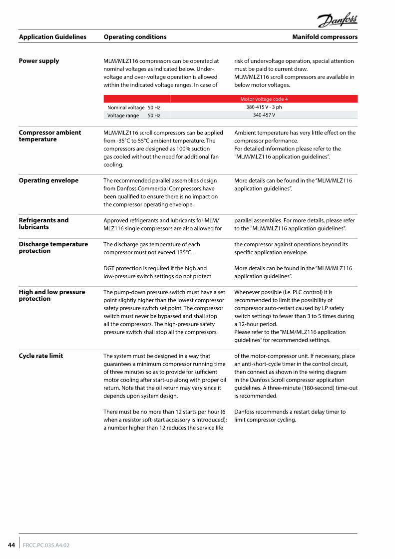
Operating conditions
MLM/MLZ116 compressors can be operated at nominal voltages as indicated below. Under-voltage and over-voltage operation is allowed within the indicated voltage ranges. In case of
risk of undervoltage operation, special attention must be paid to current draw. MLM/MLZ116 scroll compressors are available in below motor voltages.
The recommended parallel assemblies design from Danfoss Commercial Compressors have been qualified to ensure there is no impact on the compressor operating envelope.
More details can be found in the “MLM/MLZ116 application guidelines”.
Power supply
Compressor ambient temperature
Operating envelope
Discharge temperature protection
Refrigerants and lubricants
MLM/MLZ116 scroll compressors can be applied from -35°C to 55°C ambient temperature. The compressors are designed as 100% suction gas cooled without the need for additional fan cooling.
Ambient temperature has very little effect on the compressor performance.For detailed information please refer to the "MLM/MLZ116 application guidelines”.
The discharge gas temperature of each compressor must not exceed 135°C.
DGT protection is required if the high and low-pressure switch settings do not protect
the compressor against operations beyond its specific application envelope.
More details can be found in the “MLM/MLZ116 application guidelines”.
Approved refrigerants and lubricants for MLM/MLZ116 single compressors are also allowed for
parallel assemblies. For more details, please refer to the "MLM/MLZ116 application guidelines".
The pump-down pressure switch must have a set point slightly higher than the lowest compressor safety pressure switch set point. The compressor switch must never be bypassed and shall stop all the compressors. The high-pressure safety pressure switch shall stop all the compressors.
Whenever possible (i.e. PLC control) it is recommended to limit the possibility of compressor auto-restart caused by LP safety switch settings to fewer than 3 to 5 times during a 12-hour period.Please refer to the “MLM/MLZ116 application guidelines” for recommended settings.
High and low pressure protection
Cycle rate limit The system must be designed in a way that guarantees a minimum compressor running time of three minutes so as to provide for sufficient motor cooling after start-up along with proper oil return. Note that the oil return may vary since it depends upon system design.
There must be no more than 12 starts per hour (6 when a resistor soft-start accessory is introduced); a number higher than 12 reduces the service life
of the motor-compressor unit. If necessary, place an anti-short-cycle timer in the control circuit, then connect as shown in the wiring diagram in the Danfoss Scroll compressor application guidelines. A three-minute (180-second) time-out is recommended.
Danfoss recommends a restart delay timer to limit compressor cycling.
Motor voltage code 4
Nominal voltage 50 Hz 380-415 V - 3 ph
Voltage range 50 Hz 340-457 V
44 FRCC.PC.035.A4.02
Application Guidelines Manifold compressors

Operating conditions
Sump dilution control To avoid refrigerant migration to idle compressor or oil dilution in oil sump, sump superheat must be maintained at above10 K. Depending on the amount of migration below, measures shall be taken:
- add a sump heater, recommendations on sump heater are the same as single compressor guide under section “off cycle migration.”
- keep enough suction superheat, minimum suction superheat should be above 5 K.
- the idle compressor should keep running time to time.
Defrost cycle In refrigeration system applications, there are different defrost methods, such as electric heating defrost, hot gas bypass defrost, reversible defrost etc. For the system which use hot gas bypass or reversible defrost method, suction accumulator is necessary as a result of the possibility of a substantial quantity of liquid refrigerant remaining in the evaporator, this liquid refrigerant can then return to the compressor, either flooding the sump or as
a dynamic liquid slug when the cycle switch back to normal cooling operations. Sustained and repeated liquid slugging and flooding can seriously impair the oil’s ability to lubricate the compressor bearings. In such cases a suction accumulator is a must. For system using reversible defrost, it is highly recommended that both compressor should keep running or both stop during 4-way valve switch.
45FRCC.PC.035.A4.02
Application Guidelines Manifold compressors

System design recommendations
To ensure proper refrigerant and oil circulation, the speed limits in all pipes are generally recommended as follows:• For horizontal/vertical discharge gas velocity: no more than 15 m/s;• For vertical suction gas velocity: no less than 7.6 m/s;
• For horizontal suction gas velocity: no less than 3.6 m/s;• For horizontal/vertical liquid velocity: around 1.5 m/s;• For suction header gas velocity: no more than4 m/s.
Note: Suction accumulator and Oil separator etc. are not shown in this illustration, but those are necessary for the system. The graph above is only for piping design considerations.
Essential piping design considerations
Proper piping practices should be employed to ensure adequate oil return, even under minimum load conditions, with special consideration given to the size and slope of the tubing coming from the evaporator. Tubing returns from the evaporator should be designed so as not to trap oil and to prevent oil and refrigerant migration back to the compressor during off-cycles.
If the evaporator lies above the compressor, the addition of a pump-down cycle is strongly recommended. If a pump-down cycle were to be omitted, the suction line must have a loop at the evaporator outlet to prevent refrigerant from draining into the compressor during off-cycles.
If the evaporator is situated below the compressor, the suction riser must be trapped to ensure the oil return to the compressor (see fig.1).
When the condenser is mounted at a higher position than the compressor, a suitably sized U-shaped trap close to the compressor is necessary to prevent oil leaving the compressor
from draining back to the discharge side of the compressor during off-cycle. The upper loop also helps avoid condensed liquid refrigerant from draining back to the compressor when stopped (see fig. 2). The maximum elevation difference between the indoor and outdoor section cannot exceed 8 m. System manufacturers should specify precautions for any applications that exceed these limits to ensure compressor reliability.
Piping should be designed with adequate three-dimensional flexibility (figure 2). It should not be in contact with the surrounding structure, unless a proper tubing mount has been installed. This protection proves necessary to avoid excess vibration, which can ultimately result in connection or tube failure due to fatigue or wear from abrasion. Aside from tubing and connection damage, excess vibration may be transmitted to the surrounding structure and generate an unacceptable sound level within that structure as well (for more information on sound and vibration, see the section on “Sound and vibration management”).
HP
LP
>3.6 m/s
<15 m/s
0.5% >
max. 4 m
U-trap
>3.6m/sEvaporator
>7.6 m/s
max. 4 m
HP
LP
Condenser
fig1 fig2
46 FRCC.PC.035.A4.02
Application Guidelines Manifold compressors

System design recommendations
Expansion device When the parallel installation is serving a single evaporator system, the dimensioning of the expansion device (thermostatic or electronic) becomes critical and must be made in relation to both minimum and maximum capacity. This will ensure correct superheat control in all situations, with a minimum of 5 K superheat at the compressor suction. The expansion device should be sized to ensure proper control of the refrigerant flow into the evaporator. An oversized valve may result in erratic control. Proper selection could imply a slightly undersized expansion valve at full load. This consideration is especially important in manifolded units
where low load conditions may require the frequent cycling of compressors. This can lead to liquid refrigerant entering the compressor if the expansion valve does not provide stable refrigerant superheat control under varying loads. The superheat setting of the expansion device should be sufficient to ensure proper superheat levels during low loading periods. A minimum of 5 K stable superheat is required. In addition, the refrigerant charge should be sufficient to ensure proper subcooling within the condenser so as to avoid the risk of flashing in the liquid line before the expansion device.
The refrigeration compressor is designed to compress vapor only. A suction line accumulator prevents compressor damage from a sudden surge of liquid refrigerant and oil that could enter the compressor from the suction line. For low temperature application, suction accumulator is a must unless approved by careful tests under different operating conditions. If the system use hot gas bypass or reversible defrost method, suction accumulator is necessary.
Selection of a suction line accumulator should be made on the basis of the following three capabilities:
1. The accumulator should have an adequate liquid-holding capacity that can vary with the system. Normally this should not be less than 50% of the system charge. If possible, this value should be checked based on actual tests.
2. The accumulator should perform without adding excessive pressure drop to the system.
3. An accumulator should have the capability of returning oil at the proper rate and under a range of load conditions.
Guideline of suction accumulator needs to be respected in making a selection.
For efficient oil management in parallel systems the oil should return to the compressor at approximately the same rate as it leaves so that an appropriate oil level can always be maintained.
Danfoss recommends an adequately sized suction header which provides equal distribution of returning refrigerant and oil to each individual
compressor. The suction lines from the header towards each individual compressor must be fitted into the suction header. This configuration will result in a higher gas velocity at the pick-up tube inlet and proper oil return when the oil level in the suction header rises. The compressor suction lines must always enter the suction header on the topside. A recommended suction header design is shown below.
Suction accumulator
Suction header
Main suction line
Oil injection portH
D
Suction gas Suction gas to compressor
47FRCC.PC.035.A4.02
Application Guidelines Manifold compressors

System design recommendations
Oil level regulator Oil level regulator monitors the oil level and controls oil injection by switching the solenoid valve on and off to maintain an acceptable oil level in the compressor crankcase. When crankcase oil level cannot be restored within a period of time (setting value), the alarm contactor will be activated and stop the compressor to protect it from damage (some oil level regulator do not have an alarm function).
According to the function, there are three types of oil level regulator: electronic, electromechanical and mechanical. For a high-pressure oil reservoir system, Danfoss recommends individual electronic oil control regulators rather than the mechanical float ball oil regulator system for effective oil regulation.
To ensure ideal pressure equalization, the suction header must be symmetrical and the lines from the suction header to each compressor must be short and identical. These recommendations are not so critical when using an active system.
Danfoss recommends the following as necessary for secure a suction header installation:
• The suction header should be adequately sized for equal distribution of returning refrigerant gas and oil to each individual compressor; also the suction header should be installed horizontally.
• The gas velocity in the suction header must be a maximum of 4 m/s.
• The suction line and the suction header must be insulated to limit suction gas superheat.
Passive system
Oil separator / oil reservoir
Oil separator for passive system
The role of the oil separator is to intercept the mixed oil from the compressed refrigerant gas and returns it back to the compressor to assure efficient lubrication of its moving parts, and also to improve the system’s heat exchangers’ efficiency. In our manifolding system, the oil separator is necessary and is recommend to be installed in the compressor discharge line as shown below.
No oil separator category is included in this guidelines. For more details, please refer to the manufacture’s guidelines.
Regarding passive solutions, it is recommended to use an oil separator with a floating-ball valve. The floating-ball valve can control the oil flow and act as a capillary in the oil return line; therefore, there is no need to install an oil capillary in the system.
Compressor 1 Compressor 2
Suction header
From evaporator
To condenser
Oil equalization line
Non-return valve
Non-return valve
Oil separator with�oating-ball valve
Oil �lter
48 FRCC.PC.035.A4.02
Application Guidelines Manifold compressors

System design recommendations
Active system
Oil separator and reservior for active system
When an active system is adopted by the customer, the oil separator is always considered together with oil reservoir.
Due to system design, loads and defrost cycles, etc., there will be varying amounts of oil returning to the oil separator. Because of this, a safety reserve of oil is required for successful operation of the active system.
High pressure
Low pressure
Non-return valve
Suctionheader
Non-return valve
Non-return valve
Non-return valve
Combined oil separator/reservoir
Oil �lter
Non-return valve
Compressor 1
Oil level regulator Oil level regulator Oil level regulator Oil level regulator
Compressor 2 Compressor 3 Compressor 4
Danfoss recommends that high-pressure systems (oil separator installed in high pressure side) are configured in active solutions. These systems store the oil in a common oil separator/reservoir at compressor discharge pressure (see the figure below). The advantage is that these systems do not need a separated oil reservoir but make use of a combined oil separator/reservoir arrangement ,which normally results in a cost saving over traditional low-pressure systems (additional oil separator and oil reservoir installed in low pressure side). From an application point
of view, high-pressure systems are more critical than traditional low pressure systems and care must be taken to make sure that the separator/reservoir installed is of sufficient size and oil content (as per manufacturer’s recommendation) so that there is always oil stored. And pay special attention to avoid discharge gas entering the compressor oil sump, which could lead to some negative effects such as higher discharge and oil temperatures, less lubrication capability and the loss of efficiency due to hot gas bypass.
49FRCC.PC.035.A4.02
Application Guidelines Manifold compressors

Installation and service
Piping design
Wiring and rotation direction
Failure analysis
For each tandem configuration specific outline drawings are available as indicated on the following pages. These drawings must always be followed.
No changes shall be made to the indicated tubing diameter and fitting types. As for passive
systems, the oil equalization line shall be made of copper tube and assembled in such a way so that it does not extend above the connection height and must be horizontal so as not to trap oil.
Please contact Danfoss Sales for specific drawings.
All compressors in a manifolding unit must be electrically wired individually.
Compressors should run with the correct rotation direction. This can be achieved by having the correct phase sequence on each compressor motor terminal (L1-T1, L2-T2, L3-T3).
When one compressor in a parallel system fails, the chance of foreign particles entering other compressors is greatly increased. Therefore a
failure analysis must be done quickly to ensure further proper running conditions for the overall installation (i.e.: oil analysis).
50 FRCC.PC.035.A4.02
Application Guidelines Manifold compressors

Ordering information
To build a complete tandem, one must order the 2 compressors and 1 manifolding kit 7777041 plus 2 mounting kit 7777045.To build a trio, one must order 3 compressors and 1 trio manifolding kit 7777049 plus 3 mounting kit 7777045.
To build a quadro, one must order 4 compressors and 2 manifolding kit 7777041 plus 4 mounting kit 7777045. For mounting kit 7777045, please refer to guideline section “spare parts & accessories” mounting hardware.
Manifolding compressorsCombination
Manifolding kit code number Ordering number Mounting kit code
number Ordering number
Even tandem with passive system7777041 1
7777045 2Even tandem with active system 7777045 2Even trio with active system 7777049 1 7777045 3Even quadro with active system 7777041 2 7777045 4
Kit code number 7777041
Kit code number 7777049
Designation Qty
Grommet Sleeves M 6
Flat Washers LL10Z 6
Washers 6
Washer for tandem/quadro 6
Grommets 6
Sleeve 2"1/4 Rotolock - 1"3/8 ODF 2
Teflon seal Φ 50.8 mm 2
Designation Qty
Grommet Sleeves M 8
Flat Washers LL10Z 8
Washers 8
Washer for trio 8
Grommets 8
Sleeve 2"1/4 Rotolock - 1"5/8 ODF 3
Teflon seal Φ 50.8 mm 3
Note: for kit 7777041, item 6-7 are not needed for active manifolding. please leave these when assemble.
Note: for kit 7777049, items 6-7 are not needed for active manifolding. Please leave these when assembling.
51FRCC.PC.035.A4.02
Application Guidelines Manifold compressors
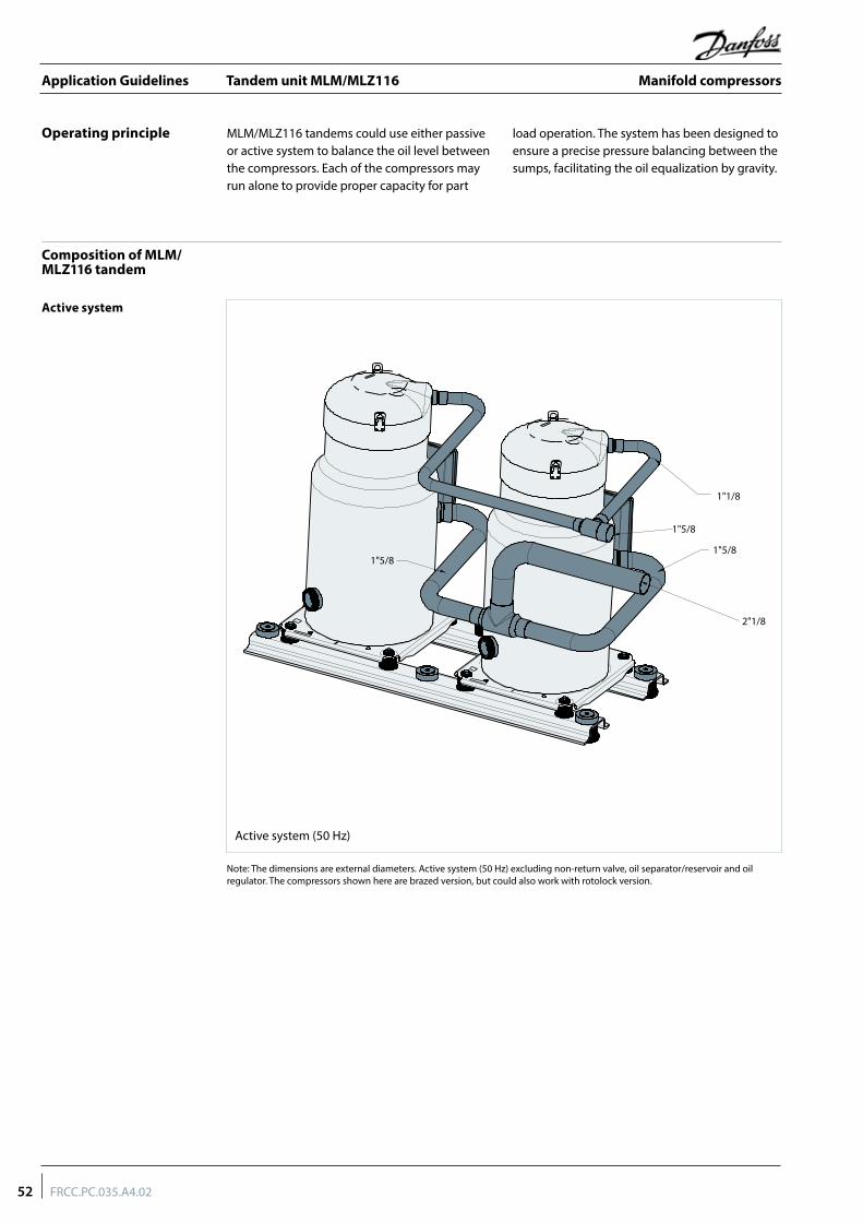
Tandem unit MLM/MLZ116
Operating principle
Composition of MLM/MLZ116 tandem
MLM/MLZ116 tandems could use either passive or active system to balance the oil level between the compressors. Each of the compressors may run alone to provide proper capacity for part
load operation. The system has been designed to ensure a precise pressure balancing between the sumps, facilitating the oil equalization by gravity.
Active system
Active system (50 Hz)
1"1/8
1"5/8
1"5/81"5/8
2"1/8
Note: The dimensions are external diameters. Active system (50 Hz) excluding non-return valve, oil separator/reservoir and oil regulator. The compressors shown here are brazed version, but could also work with rotolock version.
52 FRCC.PC.035.A4.02
Application Guidelines Manifold compressors

Tandem unit MLM/MLZ116
Passive system
Compressor mounting
Passive system (50 Hz)
Note: the dimensions are external diameters .The compressors shown here are brazed version, but could also work with rotolock version.
1"1/8
1"5/8
1"5/8(2x)
1"1/8
4"1/8
The tandem is fixed on the frame by using grommet sleeves , flat washers , washers and and the grommets , provided in kit 7777041.
HM10 x 100
Ø 25 Ø 10
Supplied with the kit 7777045
Included in kit 7777041
Not supplied
The level of oil naturally balances by a pipe of 1”3/8. To fix this oil connection equalization Rotolock, the adaptor sleeves : 2”1/4 - 1”3/8 and Teflon seals , included in kit 7777041 must be used.
Oil equalization connection
Tighteningtorque 145 Nm
53FRCC.PC.035.A4.02
Application Guidelines Manifold compressors
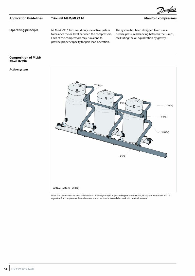
Trio unit MLM/MLZ116
Operating principle
Composition of MLM/MLZ116 trio
MLM/MLZ116 trios could only use active system to balance the oil level between the compressors. Each of the compressors may run alone to provide proper capacity for part load operation.
The system has been designed to ensure a precise pressure balancing between the sumps, facilitating the oil equalization by gravity.
Active system
Active system (50 Hz)
1"1/8 (2x)
1"5/8
1"5/8 (3x)
2"5/8
1"1/8
1"3/8
Note: The dimensions are external diameters. Active system (50 Hz) excluding non-return valve, oil separator/reservoir and oil regulator. The compressors shown here are brazed version, but could also work with rotolock version.
54 FRCC.PC.035.A4.02
Application Guidelines Manifold compressors

Trio unit MLM/MLZ116
The Trio is fixed on the frame by using grommet sleeves , flat washers , washers and and grommets , provided in kit 7777040.
Compressor mounting
HM10 x 100
Ø 25 Ø 10
Supplied with kit 7777045
Included in kit 7777049
Not supplied
55FRCC.PC.035.A4.02
Application Guidelines Manifold compressors
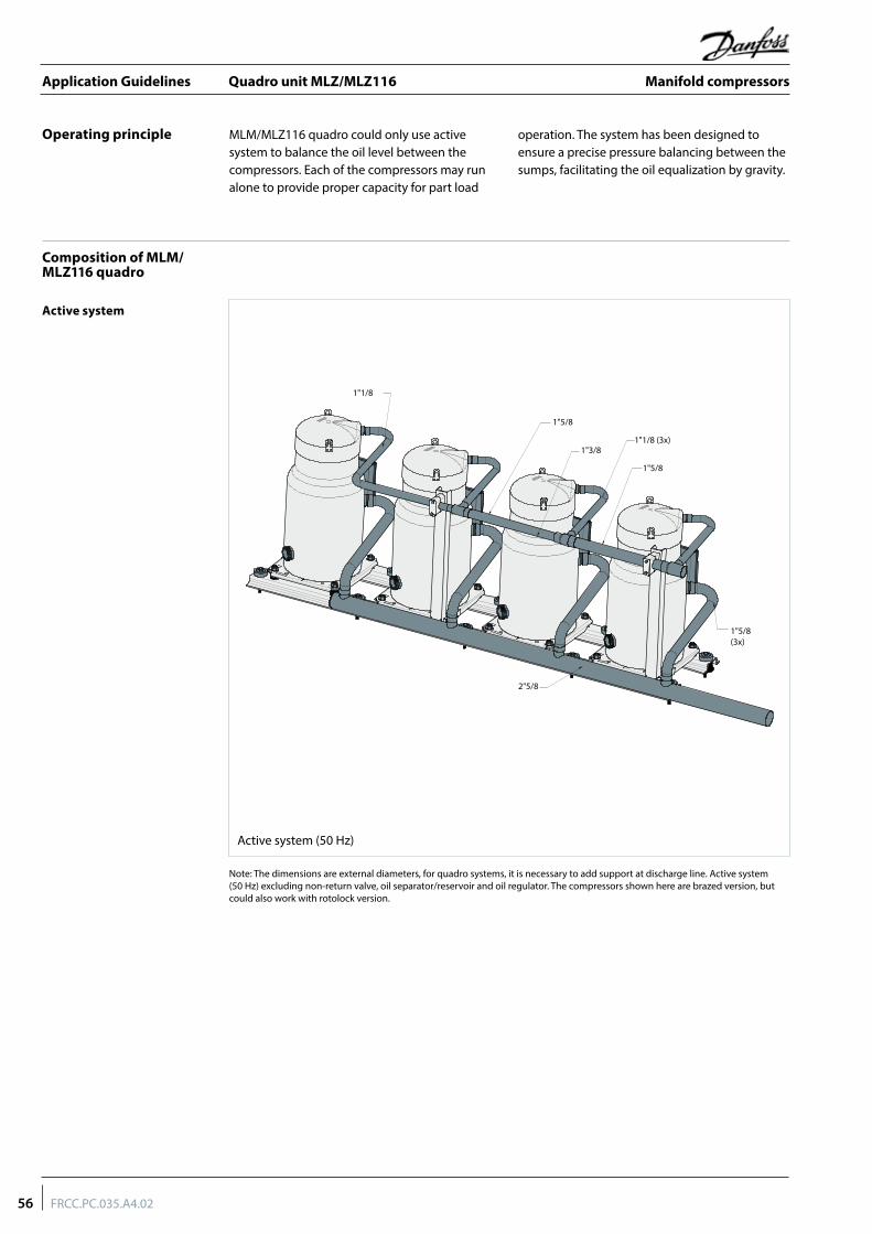
Quadro unit MLZ/MLZ116
Operating principle
Composition of MLM/MLZ116 quadro
MLM/MLZ116 quadro could only use active system to balance the oil level between the compressors. Each of the compressors may run alone to provide proper capacity for part load
operation. The system has been designed to ensure a precise pressure balancing between the sumps, facilitating the oil equalization by gravity.
Active system
Active system (50 Hz)
1"5/8
1"3/81"1/8 (3x)
1"5/8
1"1/8
1"5/8 (3x)
2"5/8
Note: The dimensions are external diameters, for quadro systems, it is necessary to add support at discharge line. Active system (50 Hz) excluding non-return valve, oil separator/reservoir and oil regulator. The compressors shown here are brazed version, but could also work with rotolock version.
56 FRCC.PC.035.A4.02
Application Guidelines Manifold compressors

Quadro unit MLZ/MLZ116
The tandem is fixed on the frame by using grommet sleeves , flat washers , washers and and the grommets , provided in kit 7777041.
Compressor mounting
HM10 x 100
Ø 25 Ø 10
Supplied with kit 7777045
Included in kit 7777041
Not supplied
57FRCC.PC.035.A4.02
Application Guidelines Manifold compressors


Danfoss Commercial Compressors is a worldwide manufacturer of compressors and condensing units for refrigeration and HVAC applications. With a wide range of high quality and innovative products we help your company to find the best possible energy efficient solution that respects the environment and reduces total life cycle costs.
We have 40 years of experience within the development of hermetic compressors which has brought us amongst the global leaders in our business, and positioned us as distinct variable speed technology specialists. Today we operate from engineering and manufacturing facilities spanning across three continents.
FRCC.PC.035.A5.02 © Danfoss | DCS (CC) | 2017.07
Our products can be found in a variety of applications such as rooftops, chillers, residential air conditioners, heatpumps, coldrooms, supermarkets, milk tank cooling and industrial cooling processes.
http://cc.danfoss.com
Danfoss Inverter Scrolls
Danfoss Turbocor Compressors
Danfoss Scrolls
Danfoss Optyma Condensing Units
Danfoss Maneurop Reciprocating Compressors
Danfoss Commercial Compressors, BP 331, 01603 Trévoux Cedex, France | +334 74 00 28 29
Danfoss Light Commercial RefrigerationCompressors