Embed Size (px)
Citation preview

SAFETY WARNINGOnly qualified personnel should install and service the equipment. The installation, starting up, and servicing of heating, ventilating, and air-conditioning equipment can be hazardous and requires specific knowledge and training. Improperly installed, adjusted or altered equipment by an unqualified person could result in death or serious injury. When working on the equipment, observe all precautions in the literature and on the tags, stickers, and labels that are attached to the equipment.
Tube Size and Component Selection
RAUJ Split Systems (20-120 Tons)R-410A RefrigerantMicrochannel Condensers
March 2012 SS-APG012-EN
Application Guide


Warnings, Cautions and Notices
Warnings, Cautions and Notices. Note that warnings, cautions and notices appear at appropriate intervals throughout this manual. Warnings are provided to alert installing contractors to potential hazards that could result in death or personal injury. Cautions are designed to alert personnel to hazardous situations that could result in personal injury, while notices indicate a situation that could result in equipment or property-damage-only accidents.
Your personal safety and the proper operation of this machine depend upon the strict observance of these precautions.
Read this manual thoroughly before operating or servicing this unit.
Important Environmental Concerns!
Scientific research has shown that certain man-made chemicals can affect the earth’s naturally occurring stratospheric ozone layer when released to the atmosphere. In particular, several of the identified chemicals that may affect the ozone layer are refrigerants that contain Chlorine, Fluorine and Carbon (CFCs) and those containing Hydrogen, Chlorine, Fluorine and Carbon (HCFCs). Not all refrigerants containing these compounds have the same potential impact to the environment. Trane advocates the responsible handling of all refrigerants—including industry replacements for CFCs such as HCFCs and HFCs.
Responsible Refrigerant Practices!
Trane believes that responsible refrigerant practices are important to the environment, our customers, and the air conditioning industry. All technicians who handle refrigerants must be certified. The Federal Clean Air Act (Section 608) sets forth the requirements for the handling, reclaiming, recovering and recycling of certain refrigerants and the equipment that is used in these service procedures. In addition, some states or municipalities may have additional requirements that must also be adhered to for responsible management of refrigerants. Know the applicable laws and follow them.
ATTENTION: Warnings, Cautions and Notices appear at appropriate sections throughout this literature. Read these carefully:
WARNING Indicates a potentially hazardous situation which, if not avoided, could result in death or serious injury.
CAUTIONsIndicates a potentially hazardous situation which, if not avoided, could result in minor or moderate injury. It could also be used to alert against unsafe practices.
NOTICE: Indicates a situation that could result in equipment or property-damage only accidents.
WARNING
Proper Field Wiring and Grounding Required!
All field wiring MUST be performed by qualified personnel. Improperly installed and grounded field wiring poses FIRE and ELECTROCUTION hazards. To avoid these hazards, you MUST follow requirements for field wiring installation and grounding as described in NEC and your local/state electrical codes. Failure to follow code could result in death or serious injury.
© 2012 Trane All rights reserved SS-APG012-EN

Warnings, Cautions and Notices
Trademarks
Trane, Frostat and the Trane logo are trademarks of Trane in the United States and other countries. All trademarks referenced in this document are the trademarks of their respective owners.
WARNING
Personal Protective Equipment (PPE) Required!
Installing/servicing this unit could result in exposure to electrical, mechanical and chemical hazards.
• Before installing/servicing this unit, technicians MUST put on all Personal Protective
Equipment (PPE) recommended for the work being undertaken. ALWAYS refer to appropriate
MSDS sheets and OSHA guidelines for proper PPE.
• When working with or around hazardous chemicals, ALWAYS refer to the appropriate MSDS
sheets and OSHA guidelines for information on allowable personal exposure levels, proper
respiratory protection and handling recommendations.
• If there is a risk of arc or flash, technicians MUST put on all Personal Protective Equipment
(PPE) in accordance with NFPA 70E or other country-specific requirements for arc flash
protection, PRIOR to servicing the unit.
Failure to follow recommendations could result in death or serious injury.
WARNING
R-410A Refrigerant under Higher Pressure than R-22!
The units described in this manual use R-410A refrigerant which operates at higher pressures than R-22 refrigerant. Use ONLY R-410A rated service equipment or components with these units. For specific handling concerns with R-410A, please contact your local Trane representative. Failure to use R-410A rated service equipment or components could result in equipment exploding under R-410A high pressures which could result in death, serious injury, or equipment damage.
ii SS-APG012-EN

Table of Contents
SS-APG012-EN iii
Overview . . . . . . . . . . . . . . . . . . . . . . . . . . . . . . . . . . . . . . . . . . . . . . . . . . . . . . . . . . . . . . 1
Background . . . . . . . . . . . . . . . . . . . . . . . . . . . . . . . . . . . . . . . . . . . . . . . . . . . . . . . 1
Updated Guidelines . . . . . . . . . . . . . . . . . . . . . . . . . . . . . . . . . . . . . . . . . . . . . . . . 2Liquid Lines . . . . . . . . . . . . . . . . . . . . . . . . . . . . . . . . . . . . . . . . . . . . . . . . . . 2Suction Lines . . . . . . . . . . . . . . . . . . . . . . . . . . . . . . . . . . . . . . . . . . . . . . . . . 2Equipment Placement . . . . . . . . . . . . . . . . . . . . . . . . . . . . . . . . . . . . . . . . . . 3
Line Sizing, Routing, and Component Selection . . . . . . . . . . . . . . . . . . . . . . . . . . . 4
Liquid Lines . . . . . . . . . . . . . . . . . . . . . . . . . . . . . . . . . . . . . . . . . . . . . . . . . . . . . . . 4Line Sizing . . . . . . . . . . . . . . . . . . . . . . . . . . . . . . . . . . . . . . . . . . . . . . . . . . . 4Routing . . . . . . . . . . . . . . . . . . . . . . . . . . . . . . . . . . . . . . . . . . . . . . . . . . . . . . 4Insulation . . . . . . . . . . . . . . . . . . . . . . . . . . . . . . . . . . . . . . . . . . . . . . . . . . . . 5Components . . . . . . . . . . . . . . . . . . . . . . . . . . . . . . . . . . . . . . . . . . . . . . . . . 5
Suction Lines . . . . . . . . . . . . . . . . . . . . . . . . . . . . . . . . . . . . . . . . . . . . . . . . . . . . . . 6Line Sizing . . . . . . . . . . . . . . . . . . . . . . . . . . . . . . . . . . . . . . . . . . . . . . . . . . . 6Routing . . . . . . . . . . . . . . . . . . . . . . . . . . . . . . . . . . . . . . . . . . . . . . . . . . . . . . 6Insulation . . . . . . . . . . . . . . . . . . . . . . . . . . . . . . . . . . . . . . . . . . . . . . . . . . . . 6Components . . . . . . . . . . . . . . . . . . . . . . . . . . . . . . . . . . . . . . . . . . . . . . . . . 7
Expansion Valves . . . . . . . . . . . . . . . . . . . . . . . . . . . . . . . . . . . . . . . . . . . . . . . . . . . . . . . 8
Controls . . . . . . . . . . . . . . . . . . . . . . . . . . . . . . . . . . . . . . . . . . . . . . . . . . . . . . . . . . . . . . . 9
Hot Gas Bypass . . . . . . . . . . . . . . . . . . . . . . . . . . . . . . . . . . . . . . . . . . . . . . . . . . . . . . . 10
Remodel, Retrofit, or Replacement . . . . . . . . . . . . . . . . . . . . . . . . . . . . . . . . . . . . . . 11
Microchannel Heat Exchanger Condensers . . . . . . . . . . . . . . . . . . . . . . . . . . . . . . 13
Examples of Field-Installed Evaporator Piping . . . . . . . . . . . . . . . . . . . . . . . . . . . . 14
Single-Circuit RAUJs . . . . . . . . . . . . . . . . . . . . . . . . . . . . . . . . . . . . . . . . . . . . . . 14
Dual-Circuit RAUJs . . . . . . . . . . . . . . . . . . . . . . . . . . . . . . . . . . . . . . . . . . . . . . . . 16
RAUJ With Braze Plate Chilled-Water Heat Exchanger . . . . . . . . . . . . . . . . . 19
Parts . . . . . . . . . . . . . . . . . . . . . . . . . . . . . . . . . . . . . . . . . . . . . . . . . . . . . . . . . . . . . . . . . 20
iv SS-APG012-EN

Overview
Trane’s RAUJ 20- through 120-ton condensing unit product line has been designed for use only with R-410A and POE oil. R-410A is a high-pressure refrigerant that requires the other components of the system, including the evaporator, to be rated for R-410A pressures. For compressor lubrication, the refrigerant requires POE oil.
Traditionally, refrigerant piping practices were guided by four principles:
• Return the oil to the compressor.
• Maintain a column of liquid at the expansion valve.
• Minimize the loss of capacity.
• Minimize the refrigerant charge in the system.
These piping practices are similar for R-410A and POE oil. However, because of the different mass flows and pressures, the line diameter required to carry the oil and refrigerant may not be the same as a similar tonnage R-22 unit. Also, the allowable pressure drop may be greater for R-410A than R-22.
Evidence accumulated over years of observation demonstrates that the lower the refrigerant charge, the more reliably a split air-conditioning system performs. Any amount of refrigerant in excess of the minimum design charge becomes difficult to manage. The excess refrigerant tends to collect in areas that can interfere with proper operation and eventually shortens the service life of the system.
To successfully minimize the system refrigerant charge, the correct line size should be used and the line length must be kept to a minimum.
Background
In a split air-conditioning system, the four major components of the refrigeration system are connected by field-assembled refrigerant piping (Figure 1). A suction line connects the evaporator to the compressor, the discharge line connects the compressor to the condenser, and the liquid line connects the condenser to the expansion device, which is located near the evaporator inlet. Operational problems can occur if these refrigerant lines are designed or installed improperly. .
microchannel condenser(outdoor coil)
liquid line
expansiondevice
evaporator (indoor coil)
compressor
suctionline
dischargeline
Figure 1. Interconnecting refrigerant lines in a typical split air-conditioning system
SS-APG012-EN 1

Overview
The origin of the requirements for equivalent line lengths of components, line pressure drop, and minimum and maximum refrigerant velocities is uncertain. It appears likely that at least some of the supporting data was derived from measurements and/or equations involving water. Some resource materials even show water components when illustrating refrigerant piping requirements.
Subsequent reviews of analytical and empirical data for refrigerant piping resulted in the publication of two research papers: Pressure Losses in Tubing, Pipe, and Fittings by R.J.S. Pigott and Refrigerant Piping Systems — Refrigerants 12, 22, 500 by the American Society of Refrigeration Engineers (ASRE). In his paper, Pigott described his use of refrigerant as the fluid and his direct measurement of pressure drops. His findings indicated that the pressure drop of many line components is small and difficult to measure. For these components, he used experimental data to derive a formula relating the geometry of the component to its pressure drop. Overall, his calculated pressure loss of the components was less than originally determined.
The conclusion of the ASRE research paper stated that the minimum required velocity to maintain oil entrainment in vertical risers and horizontal lines will vary with the diameter of the tube and with the saturation temperature of the suction gas. In other words, the minimum required velocity for oil entrainment is not constant.
Updated Guidelines
Liquid Lines
Historically, liquid lines were sized to minimize the pressure losses within the piping circuit. Oil movement through the piping wasn’t a concern (nor is it today) because oil is miscible in liquid refrigerant at normal liquid-line temperatures. The historic and traditional 6 psid liquid line pressure drop had the unintended consequence of requiring line sizes with large internal refrigerant volumes. Since our objective is also to minimize the refrigerant charge to make the most reliable systems, we increased the allowable liquid pressure drop to 35 psid (R-22), which allows for the selection of a smaller liquid line while still maintaining refrigeration operation. With R-410A refrigerant and POE oil, this pressure drop can be as high as 50 psid. Within these guidelines, refrigeration operation is maintained while minimizing the refrigerant charge. It is still required to limit the liquid line velocity to 600 ft/min to help avoid issues with water hammer.
Suction Lines
R-410A is a high-pressure refrigerant and allows higher-pressure drops in the suction lines. With R-22, a 2°F loss in the suction line means a pressure drop of 3 psi. With R-410A refrigerant, that same 2°F loss is a 5 psi drop. Additional pressure drop may be tolerated in certain applications.
R-410A refrigerant suction lines must be sized to maintain oil-entrainment velocities in both the horizontal and vertical risers. Oil entrainment for R-410A is based on suction temperature as well as tube diameter. At the time of this writing, no known direct oil-entrainment tests have been conducted. Trane has used ASHRAE data to create equation-based formulas to predict the entrainment velocities of R-410A refrigerant and POE oil. These minimum velocities are reflected in the line sizes listed in the component selection summary (Table 1, p. 20).
2 SS-APG012-EN

Overview
Equipment Placement
Minimize Distance Between Components
For a split air-conditioning system to perform as reliably and inexpensively as possible, the refrigerant charge must be kept to a minimum. To help accomplish this design goal:
• Site the outdoor unit as close to the indoor unit as possible.
• Route each interconnecting refrigerant line by the shortest and most direct path so that line lengths and riser heights are no longer than absolutely necessary.
• Use only horizontal and vertical piping configurations.
• Determine whether the total length of each refrigerant line requires Trane review. Be sure to account for the difference in elevations of the indoor and outdoor units when calculating the total line length.
Interconnecting lines of 150 lineal ft (45.7 m) or less do not require Trane review, but only a limited amount may be in a riser (see Figure 2 and Figure 3).
.
RAUJ
Acceptable suction-riser height
based on total suction-line length
(RAUJ above indoor unit)
Figure 2. Allowable elevation difference: Cooling-only RAUJ above indoor unit
RAUJ
Acceptable liquid-riser height
based on total liquid-line length
(RAUJ below indoor unit)
Figure 3. Allowable elevation difference: Cooling-only RAUJ below indoor unit
SS-APG012-EN 3

Line Sizing, Routing, and Component Selection
Figure 4 illustrates an example of an RAUJ split-system component arrangement. Use it to determine the proper, relative sequence of the components in the refrigerant lines that connect the RAUJ condensing unit to an evaporator coil. Refer to “Examples of Field-Installed Evaporator Piping,” p. 14, for more detailed schematics of evaporator piping. The RAUJ units are R-410A machines, and all the selected components installed in the field must also be rated for use with R-410A.
Liquid Lines
Line Sizing
Properly sizing the liquid line is critical to a reliable split-system application. Table 1, p. 20 shows the recommended liquid-line sizing for each RAUJ model based on its nominal capacity. Using the preselected tube diameter to uniformly size the liquid line will maintain operating requirements and is the line size around which the RAUJ installation literature charging charts were generated. Increasing the line size will not increase the allowable line length.
Routing
Install the liquid line with a slight slope in the direction of flow so that it can be routed with the suction line.
A height limitation exists for liquid lines that include a liquid riser because of the loss of subcooling that accompanies the pressure loss in the height of the liquid column. Figure 3, p. 3, depicts the permissible rise in the liquid line (without excessive loss of subcooling). Again, system designs outside the application envelope of the RAUJ unit require Trane review.
The RAUJ unit design includes a liquid line check/relief assembly at the outlet of the subcooler to prevent liquid refrigerant from being drawn back to the compressor during the off cycle. The relief
Figure 4. Example of placement for split-system components
suction line
expansionvalves
moisture-indicatingsight glass
solenoidvalve filter drier
withaccess port
manualball valve
accessport
access port
distributor
coil module
Frostat™control
manual ball valve
condensing unit
compressors
dischargeline
manualangle valves
manualball valve
liquid line
accessport
manualball valve
check/relief valve
evap
ora
tor
coil
con
den
ser
and
su
bco
ole
r co
il
filter
access port
king valve access port
4 SS-APG012-EN
Line Sizing, Routing, and Component Selection
valve discharges to the condenser to prevent excessive pressures from developing in the liquid line during the off cycle, due to a temperature change of the trapped column of liquid between the solenoid valve and check valve.
Insulation
The liquid line is generally warmer than the surrounding air, so it does not require insulation. In fact, heat loss from the liquid line improves system capacity because it provides additional subcooling. However, if the liquid line is routed through a high-temperature area, such as an attic or a mechanical room, insulation would be required.
Components
Liquid-line refrigerant components necessary for a successful job include a filter drier, access port, solenoid valve, moisture-indicating sight glass, expansion valve(s), and ball shutoff valves. Figure 4, p. 4 illustrates how to sequence the components properly in the liquid line. Position the components as close to the evaporator as possible. Table 1, p. 20, identifies suitable components, by part number, for each RAUJ model. Note that there are two access ports: one located at the RAUJ and one located at the evaporator. Tables 2 through 4 (pp. 21-22) list suitable expansion valves.
Liquid Filter Drier
There is no substitute for cleanliness during system installation. The liquid filter drier prevents residual contaminants, introduced during installation, from entering the expansion valve and solenoid valve. If choosing a filter other than the one listed in Table 1, make sure its volume, filtering, and moisture-absorbing characteristics are equivalent, and that it is the replaceable core type.
Access Port
The access port located at the RAUJ allows the unit to be charged with liquid refrigerant and is used to determine charge level. This port is usually a Schraeder valve with a core.
Solenoid Valve
In RAUJ split systems with MCHE, solenoid valves isolate the refrigerant from the evaporator during the off cycles. Trim solenoids cannot be used with MCHE (refer to “Microchannel Heat Exchanger Condensers,” p. 13).
Note: RAUJ units with MCHE no longer employ pump-down, but isolation solenoids are required. The suggested solenoid uses a 120-volt service and requires code-compliant wiring to the RAUJ condensing unit. For more information, see “Microchannel Heat Exchanger Condensers,” p. 13.
Moisture-Indicating Sight Glass
Be sure to install one moisture-indicating sight glass in the main liquid line.
Note: The sole value of the glass is its moisture-indicating ability. Use the Installation manual charging curves—not the sight glass—to determine proper charge levels. A properly charged RAUJ unit may show bubbles in the sight glass.
Expansion Valve
The expansion valve is the throttling device that meters the refrigerant into the evaporator coil. Metering too much refrigerant floods the compressor; metering too little elevates the compressor temperature. Choosing the correct size and type of expansion valve is critical to ensure that it will correctly meter refrigerant into the evaporator coil throughout the entire operating envelope of the system. Correct refrigerant distribution into the coil requires an expansion valve for each distributor.
SS-APG012-EN 5

Line Sizing, Routing, and Component Selection
For improved modulation, choose expansion valves with balanced port construction and external equalization. Tables 2 through 4 (pp. 21-22) identify the part numbers of the valves suggested for commercial RAUJ MCHE systems.
The tonnage of the valve should represent the tonnage of the portion of coil that the TXV/distributor will feed. Systems with microchannel condenser coils with fin and tube evaporators require a TXV with a bleed port to prevent high-pressure control trips.
Ball Shutoff Valves
Adding manual, ball-type shutoff valves upstream and downstream of the filter simplifies replacement of the filter core. As a matter of practicality, Table 1, p. 20, lists only one of the numerous manufacturers of these valves. If you choose a valve by another manufacturer, ensure that its specifications are equivalent to the valve identified in this guide.
Suction Lines
Line Sizing
Proper line sizing is required to guarantee that the oil returns to the compressor throughout the system’s operating envelope. At the same time, the line must be sized so that the pressure drop does not excessively affect capacity or efficiency. To accomplish both objectives, it may be necessary to use two different line diameters: one for the horizontal run and for the vertical drops, and another for the vertical lifts (risers).
Note: Preselected suction-line diameters shown in Table 1 are independent of total line length for properly charged 20-120 ton RAUJ units in normal air-conditioning applications.
Routing
To prevent residual or condensed refrigerant from “free-flowing” toward the compressor during the off cycle, install the suction line so that it slopes by ¼ to 1 inch per 10 feet of run (1 cm per 3 m) toward the evaporator.
When the application includes a suction riser, oil must be forced to travel the height of the riser. Riser traps are unnecessary in the suction line. They will add pressure drop. Double risers must not be used. They not only add pressure drop but can hold great amounts of oil—oil better used in the compressor.
All 20- through 120-ton RAUJ units unload such that a single line size, preselected in Table 1, provides sufficient lift to entrain oil up the permissible riser height. To ensure proper oil movement, the permissible unit separation is 150 ft (45.7 m), including a maximum vertical suction rise of 50 ft (15 m). System designs outside this application envelope require Trane review.
Note: If a suction riser is properly sized, oil will return to the compressor regardless of whether a trap is present. If a suction riser is oversized, adding a trap will not restore proper oil entrainment.
Avoid Underground Refrigerant Lines
Refrigerant condensation during the off cycle, installation debris inside the line (including condensed ambient moisture), service access, and abrasion/corrosion can quickly impair reliability.
Insulation
Any heat that transfers from the surrounding air to the cooler suction lines increases the load on the condenser (reducing the system’s air-conditioning capacity) and promotes condensate formation. After operating the system and testing all fittings and joints to verify that the system is leak-free, insulate suction lines to prevent heat gain and unwanted condensation.
6 SS-APG012-EN
Line Sizing, Routing, and Component Selection
Components
The suction line requires field installation of these components: a filter1, access port, Frostat™ control for coil frost protection2, and ball shutoff valve. Position them as close to the compressor as possible. Table 1, p. 20, identifies suitable components by part number for each RAUJ model.
Note: Placement of the Frostat control is illustrated in Figure 4, p. 4.
Filter
The suction filter prevents contaminants, introduced during installation, from entering the compressor. For this reason, the suction filter should be the replaceable-core type, and a clean core should be installed after the system is cleaned up.
To prevent oil logging, ensure the filter is oriented to free drain.
As a matter of practicality, Table 1 lists only one of the many manufacturers of suction-line filters. If you choose a filter by another manufacturer, ensure that its capability and volume are equivalent to the suction filter identified in this guide.
Access Port
The access port is used to determine suction pressure. This port is usually a Schraeder valve with a core.
Frostat™ DX Fin Tube Coil Frost Protection
The Frostat control is the preferred method for protecting the evaporator coils from freezing on typical comfort cooling applications. It senses the suction-line temperature and temporarily disables mechanical cooling if it detects frost conditions. The control is mechanically attached to the outside of the refrigerant line, near the evaporator, and wired to the unit control panel.
Ball Shutoff Valve
Adding manual, ball-type shutoff valves upstream and downstream of the filter simplifies replacement of the filter core.
As a matter of practicality, Table 1 lists only one of the numerous manufacturers of these valves. If you choose a valve by another manufacturer, ensure that its specifications are equivalent to the valve identified in this guide.
1 Unit in excess of 80’; > 10 fittings; or a portion underground (underground lines should be avoided)2 Optional by application
SS-APG012-EN 7

8 SS-APG012-EN
Expansion Valves
Expansion valves meter refrigerant into the evaporator under controlled conditions. If there is too much refrigerant, the refrigerant will not completely vaporize and the remaining liquid will slug the compressor. If there is too little refrigerant, there may not be enough cooling for the compressor.
There are two types of valves:
• Standard valves are used on the RAUJ MCHE systems with braze plate chilled-water evaporators.
• Bleed port valves are used on RAUJ MCHE systems with fin tube DX evaporators. They have an internal port that shunts the refrigerant around the modulating portion of the valve.
Tables 2 through 4 (pp. 21-22) list expansion valves. Each evaporator distributor requires a dedicated expansion valve in order to maintain proper coil distribution. The expansion valve should be selected to match the capacity of the coil that the distributor feeds.
Example 1: 20-ton coil with two equal distributors
20 / 2 = 10
Each TXV should be selected for 10 tons.
Example 2: 30-ton coil with two distributors and a 60/40 coil split
30 x .6 = 18 and 30 x .4 = 12
One TXV should be sized for 18 tons, and one TXV should be sized for 12 tons.
If the coil or distributors have a difference of only one circuit tube, the difference should be ignored.
The proper balance for feeding refrigerant for an RAUJ system is to provide 18°F of superheat—the difference between the saturated and actual refrigerant temperature leaving the evaporator. On bleed port valves, the expansion valve superheat is set high from the manufacturer. These valves will need to be adjusted to 18°F superheat.

SS-APG012-EN 9
Controls
The RAUJ unit is available with different control options depending on unit tonnage. These control options include VAV operation, CV operation, chilled-water operation and a “no controls” option. The no controls option is often selected when a controls contractor wants to stage the RAUJ compressors.
It is important to understand that when the staging of compressors is turned over to a third party, the compressor protection, provided through system stability, is also turned over to the third party. Simply stated, this means that when a compressor turns on, it shouldn’t turn off until the expansion valve comes under control. And, once the compressor turns off, it should be allowed to stay off until the crank case heater has warmed up.
There are timers in the RAUJ unit compressor staging; however, they are not meant to accomplish system stability. System stability must be programmed in the system controls. To accomplish this, the system controls must incorporate a 5-minute-on, a 5-minute-off, and a 5-minute-interstage differential on each compressor stage.
Comment About Evaporator Chillers
Special consideration must be given to RAUJ units with evaporator chillers. Controls must provide the stability described above, but they must also prevent the chiller from freezing. It is recommended that the standard Trane control be used or that Trane’s local building automation controls department control the chiller.

10 SS-APG012-EN
Hot Gas Bypass
Many years ago, hot gas bypass (HGBP) was successfully added to HVAC systems to correct a number of operational problems. Hoping to avoid such problems altogether, it eventually became common practice for designers to specify hot gas bypass in new systems. Unfortunately, the practice often degraded rather than improved reliability.
Hot gas bypass increases the minimum refrigerant charge; it also inflates the first cost of the system. Besides adding more paths for potential refrigerant leaks, hot gas bypass increases the likelihood of refrigerant distribution problems. Finally, hot gas bypass uses excessive amounts of energy by preventing the compressors from cycling with fluctuating loads.
Trane now has more than 15 years experience in the successful use of packaged rooftop equipment without hot gas bypass in commercial comfort-cooling applications. To prevent evaporator freeze-up, our equipment typically includes Trane® Frostat™ coil frost protection.
Like hot gas bypass, the Frostat system protects the coil from freezing, but it does so by turning off compressors when a sensor detects the formation of frost on the evaporator coil. The compressor is released to operate when the coil temperature rises a few degrees above the frost threshold. The Frostat control strategy reduces the overall energy consumption of the system while maintaining system control.
Systems should be designed to avoid HGBP whenever possible.
Chilled-Water Systems
Chilled-water systems may require HGBP because of widely and quickly varying loads. Chilled-water comfort cooling applications, however, seldom need HGBP.
One way to mitigate the necessity of HGBP is to include a supply tank that has 5-minute storage. In all cases, the loop time1of the system should be 5 minutes.
Additional Resource
• For more information about HGBP, refer to the Engineers Newsletter, “Hot Gas Bypass – Blessing or a Curse?” (ADM-APN007-EN).
1
gal/min
water in the system, gal

Remodel, Retrofit, or Replacement
Inevitably, older condensing units and evaporator systems will need to be replaced or retrofitted. Due to the phase-out of many of these older refrigerants, the major components for those older units or systems may no longer be available. The only option will be to convert the system to R-410A, POE oil, and R-410A components.
When upgrading an existing refrigerant split system due to remodel, retrofit, or replacement, the entire system must be reviewed for compatibility with R-410A and POE oil. Each and every part of the split HVAC system MUST be compatible with the properties of R-410A refrigerant and POE oil. In addition, ensure the existing electrical service is adequate for the product being installed.
Every part of an existing split system needs to be analyzed to determine if it can be reused in an R-410A and POE oil system:
• R-22 condensing units will not work with R-410A; they must be replaced.
• Most older evaporator coils were not pressure- and cycle-rated for R-410A pressures. If they weren’t, they will need to be replaced. If they were properly pressure-rated for R-410A, existing coils must be modeled to determine if they will meet capacity requirements, are properly circuited, have correctly sized distributor tubes, and employ acceptable distributors and orifices.
• The required R-410A line sizes may be different than the existing line sizes. The lines need to be re-sized and compared to existing lines for reusability.
• Suction lines 2-5/8 OD and smaller of type L copper are suitable for use with R-410A. Suction lines 3-1/8 OD must use type K or thicker wall.
• Discharge lines, liquid lines, heat pump vapor lines, and hot gas bypass lines 1-3/8 OD and smaller of type L copper are suitable for use with R-410A. These same lines sized at 1-5/8 OD or 2-1/8 OD must use type K or thicker wall.
• Expansion valves need to be reselected. Expansion valves are refrigerant specific.
• Any gasket or o-ring should be replaced. Shrinkage of the original seal may occur after an HFC conversion, potentially causing a refrigerant leak. Components commonly affected are Schraeder cores, solenoid valves, ball valves, and flange seals. But all external seals in contact with refrigerant should be viewed as potential leak sources after a retrofit.
• All other valves, filters, valve packing, pressure controls, and refrigeration accessories must be researched through their manufacturer for compatibility with the pressures of an R-410A system, and for their compatibility with the newer POE oil.
• For the best performance and operation, the original mineral oil should be removed from the components of the system that are not being replaced. Any component of the system that is suspected of trapping oil (piping, traps, and coil), should be dismantled, drained, and reassembled. After all components have been drained, the amount of residual mineral oil will have a negligible effect on performance and reliability.
New with MCHE • Trim solenoid valves cannot be used.
• RAUJ MCHE units must have an isolation solenoid but will not pump down.
WARNING
R-410A Refrigerant under Higher Pressure than R-22!
The units described in this manual use R-410A refrigerant which operates at higher pressures than R-22 refrigerant. Use ONLY R-410A rated service equipment or components with these units. For specific handling concerns with R-410A, please contact your local Trane representative. Failure to use R-410A rated service equipment or components could result in equipment exploding under R-410A high pressures which could result in death, serious injury, or equipment damage.
SS-APG012-EN 11

Remodel, Retrofit, or Replacement
All Codes take precedence over anything written here.
NOTICE:
Compressor Damage!
POE oil is hygroscopic – it absorbs water directly from the air. This water is nearly impossible to remove from the compressor oil and can cause compressor failures. For this reason, the system should not be open for longer than necessary, dry nitrogen should flow in the system while brazing, and only new containers of oil should be used for service and maintenance.
12 SS-APG012-EN

SS-APG012-EN 13
Microchannel Heat Exchanger Condensers
The microchannel heat exchanger (MCHE) condenser design is quite similar to the design of an automobile radiator. Refrigerant is distributed to very small channels in a thin plate. There are any number of thin plates, one above the other, separated by fins (Figure 5).
This design improves heat transfer and the refrigerant that enters the coil quickly turns to liquid. The MCHE tube volume holds very little refrigerant, so the refrigerant charge of the system is reduced. However, the tube volume is so small that if the flow of refrigerant out of the MCHE condenser is slowed much more than the flow of refrigerant into the MCHE condenser, the condenser may quickly fill with liquid and cause a high-pressure control trip. To avoid this condition, three system design changes have been made on the RAUJ unit with MCHE:
1. No pump-down: The storage capacity of the MCHE won’t support pump-down. A liquid solenoid is still required and closes simultaneously as the circuit cooling shuts off.
2. No trim solenoid: The storage capacity of the MCHE won’t support partial shut-off of the evaporator coil.
3. Bleed port TXVs: As the TXV hunts to find the proper superheat, the liquid restriction caused by the natural closing of a non-bleed TXV can excessively slow the refrigerant leaving the condenser. At this condition, the bleed port TXV allows enough refrigerant to pass through the bleed port of the valve to prevent high-pressure issues.
Exception: The RAUJ unit that uses braze plate chilled-water evaporators does not need a bleed port TXV. This type evaporator doesn’t hold enough refrigerant to cause the high-pressure issue described. Because of the low refrigerant volume, the control system does not need to pump down but will still require a liquid line solenoid for charge isolation.
Figure 5. MCHE condenser
fins
microchannel flat tube
header (top removed)

Examples of Field-Installed Evaporator Piping
Single-Circuit RAUJs
Figure 6. Type UF evaporator coil with one distributor
Figure 7. Type UF evaporator coil with two distributors
thermalexpansionvalve (TXV)
liquidline
filter drierisolationsolenoid
valve
sightglass
distributor
suction line
Evaporator Coil with
Standard Circuiting
1. Pitch the liquid line slightly — 1 in. / 10 ft (1 cm / 3 m) — so that the refrigerant drains toward the evaporator.
2. Provide one expansion valve per distributor.
3. Slightly pitch the outlet line from the suction header toward the suction riser — that is, 1 in. / 10 ft (1 cm / 3 m) in the direction of flow. Use the tube diameter that matches the suction-header connection.
4. Use the tube diameter recommended for a vertical rise in Table 1, p. 20. Ensure that the top of the riser is higher than the evaporator coil.
5. Pitch the suction line slightly — 1 in. / 10 ft (1 cm / 3 m) — so that the refrigerant drains toward the evaporator.
6. Insulate the suction line.
Evaporator Coil
with Horizontal-Split
(Standard) Circuiting
thermalexpansionvalve (TXV)
liquidline
filter drierisolationsolenoid
valve
sightglass
distributor
suction lineEvaporator Coil with
Intertwined Circuiting
thermalexpansionvalve (TXV)
liquidline
filter drier
sightglass
distributor
suction line
isolationsolenoid
valve
1. Pitch the liquid line slightly — 1 in. / 10 ft (1 cm / 3 m) — so that the refrigerant drains toward the evaporator.
2. Provide one expansion valve per distributor.
3. Slightly pitch the outlet line from the suction header toward the suction riser — that is, 1 in. / 10 ft (1 cm / 3 m) in the direction of flow. Use the tube diameter that matches the suction-header connection. Use a double-elbow configuration to isolate the TXV bulb from other suction headers.
4. This looks like a trap, but is actually due to the requirement that the refrigerant gas leaving the coil flows downward, past the lowest suction-header outlet, before turning upward.
5. Use the “horizontal” tube diameter identified in Table 1, p. 20.
6. Use the tube diameter recommended for a vertical rise in Table 1. Ensure that the top of the riser is higher than the evaporator coil.
7. Pitch the suction line slightly — 1 in. / 10 ft (1 cm / 3 m) — so that the refrigerant drains toward the evaporator.
8. Insulate the suction line.
9. Install a single isolation solenoid valve between the liquid-line filter drier and the sight glass.
Note: Due to reduced Microchannel condenser volumes, do not use “trim” solenoid valves.
14 SS-APG012-EN

Examples of Field-Installed Evaporator Piping
Figure 8. Type UF evaporator coil with four distributors
thermal expansionvalves (TXV)
liquidline
filter drierisolationsolenoid
valve
sightglass
distributor
suction line
Evaporator Coil
with Horizontal-Split
(Standard) Circuiting
thermal expansionvalves (TXV)
liquidline
filter drier
sightglass
distributor
suction line Evaporator Coil with
Intertwined Circuiting
isolationsolenoid
valve
1. Pitch the liquid line slightly — 1 in. / 10 ft (1 cm / 3 m) — so that the refrigerant drains toward the evaporator.
2. Provide one expansion valve per distributor.
3. Slightly pitch the outlet line from the suction header toward the suction riser — that is, 1 in. / 10 ft (1 cm / 3 m) in the direction of flow. Use the tube diameter that matches the suction-header connection.
4. This looks like a trap, but is actually due to the requirement that the refrigerant gas leaving the coil flows downward, past the lowest suction-header outlet, before turning upward. Use a double-elbow configuration to isolate the TXV bulb from other suction headers.
5. Use the “horizontal” tube diameter identified in Table 1, p. 20.
6. Use the tube diameter recommended for a vertical rise in Table 1. Ensure that the top of the riser is higher than the evaporator coil.
7. Pitch the suction line slightly — 1 in. / 10 ft (1 cm / 3 m) — so that the refrigerant drains toward the evaporator.
8. Insulate the suction line.
9. Install a single isolation solenoid valve between the liquid-line filter drier and the sight glass.
Note: Due to reduced Microchannel condenser volumes, do not use “trim” solenoid valves.
SS-APG012-EN 15
Examples of Field-Installed Evaporator Piping
Dual-Circuit RAUJs
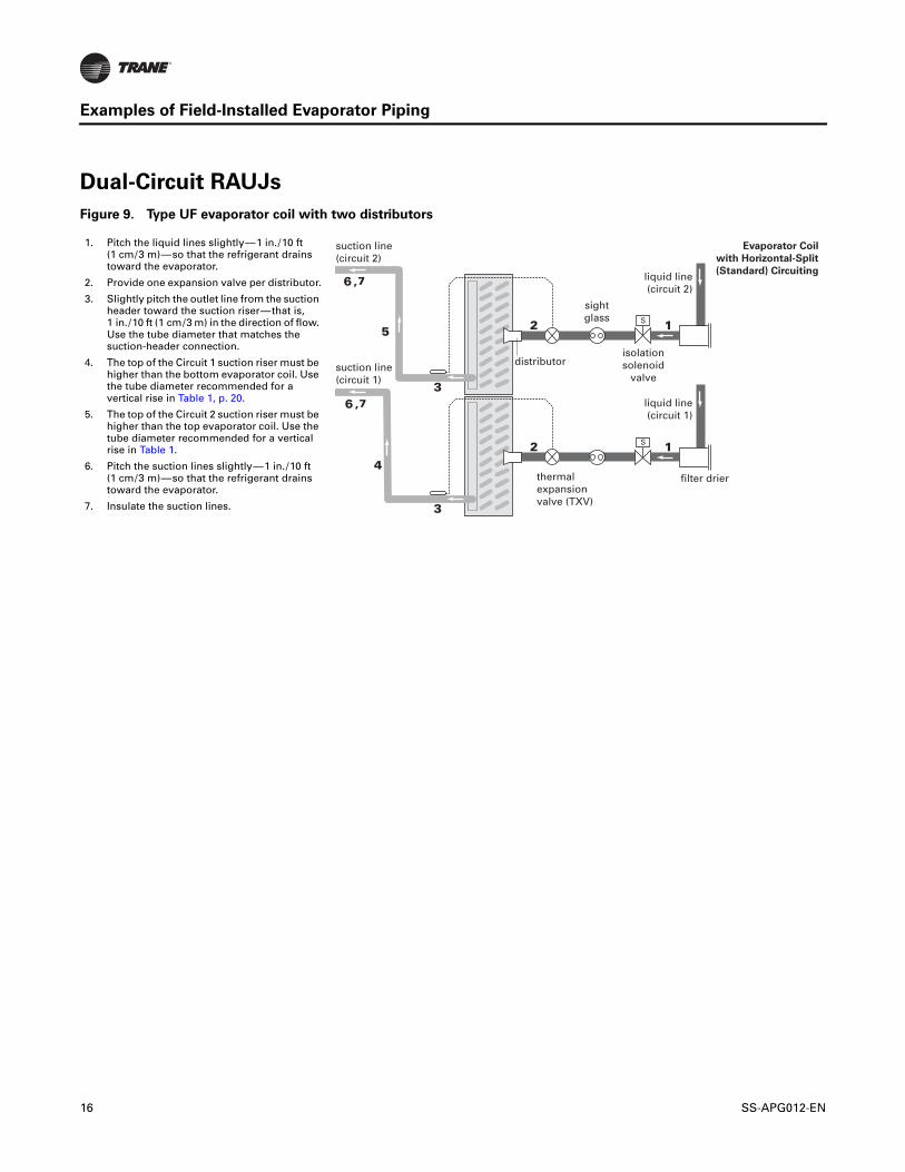
Figure 9. Type UF evaporator coil with two distributors
liquid line(circuit 2)
isolationsolenoid
valve
sightglass
suction line(circuit 2)
thermalexpansionvalve (TXV)
liquid line(circuit 1)
distributorsuction line(circuit 1)
Evaporator Coil
with Horizontal-Split
(Standard) Circuiting
filter drier
1. Pitch the liquid lines slightly — 1 in. / 10 ft (1 cm / 3 m) — so that the refrigerant drains toward the evaporator.
2. Provide one expansion valve per distributor.
3. Slightly pitch the outlet line from the suction header toward the suction riser — that is, 1 in. / 10 ft (1 cm / 3 m) in the direction of flow. Use the tube diameter that matches the suction-header connection.
4. The top of the Circuit 1 suction riser must be higher than the bottom evaporator coil. Use the tube diameter recommended for a vertical rise in Table 1, p. 20.
5. The top of the Circuit 2 suction riser must be higher than the top evaporator coil. Use the tube diameter recommended for a vertical rise in Table 1.
6. Pitch the suction lines slightly — 1 in. / 10 ft (1 cm / 3 m) — so that the refrigerant drains toward the evaporator.
7. Insulate the suction lines.
16 SS-APG012-EN
Examples of Field-Installed Evaporator Piping
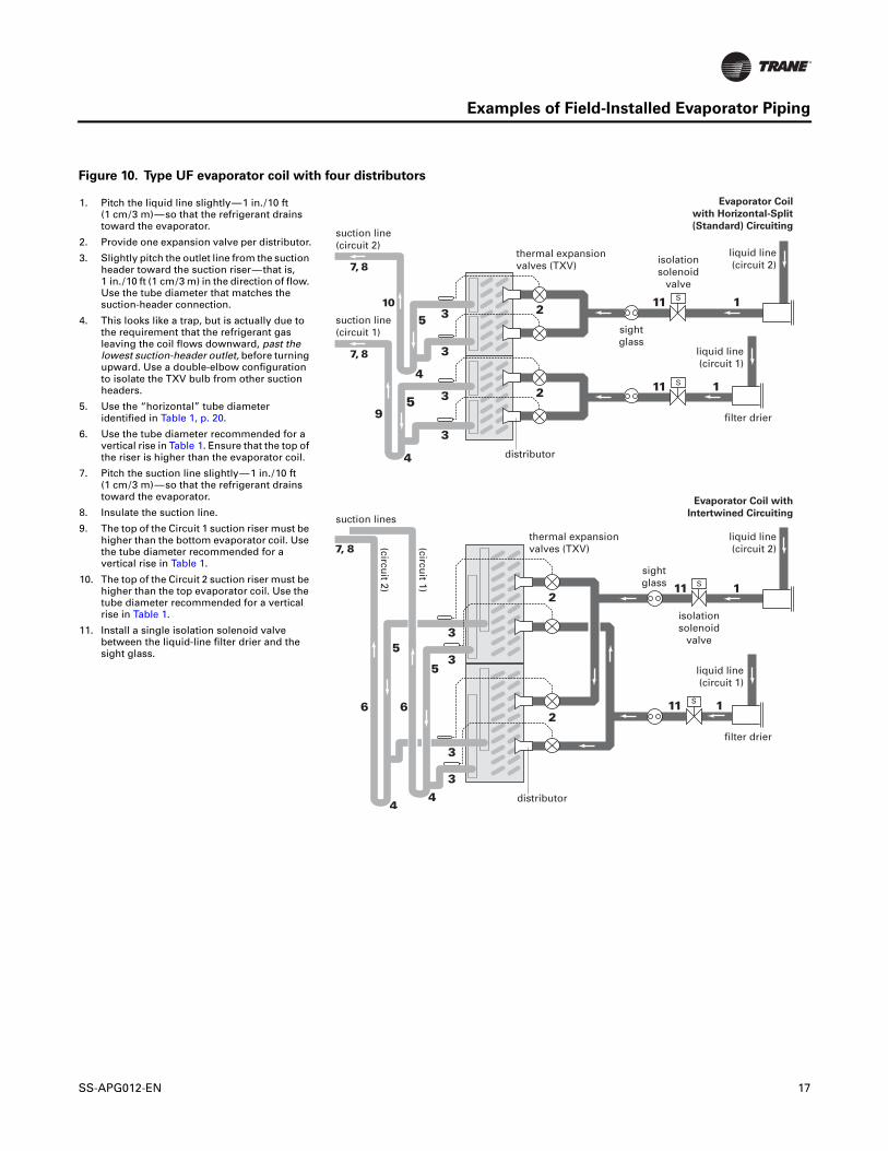
Figure 10. Type UF evaporator coil with four distributors
liquid line(circuit 1)
filter drier
thermal expansionvalves (TXV)
liquid line(circuit 2)
distributor
isolationsolenoid
valve
sightglass
Evaporator Coil
with Horizontal-Split
(Standard) Circuiting
thermal expansionvalves (TXV)
distributor
suction lines
Evaporator Coil with
Intertwined Circuiting
suction line(circuit 2)
suction line(circuit 1)
liquid line(circuit 1)
filter drier
liquid line(circuit 2)
isolationsolenoid
valve
sightglass
(circuit 1)
(circuit 2)
1. Pitch the liquid line slightly — 1 in. / 10 ft (1 cm / 3 m) — so that the refrigerant drains toward the evaporator.
2. Provide one expansion valve per distributor.
3. Slightly pitch the outlet line from the suction header toward the suction riser — that is, 1 in. / 10 ft (1 cm / 3 m) in the direction of flow. Use the tube diameter that matches the suction-header connection.
4. This looks like a trap, but is actually due to the requirement that the refrigerant gas leaving the coil flows downward, past the lowest suction-header outlet, before turning upward. Use a double-elbow configuration to isolate the TXV bulb from other suction headers.
5. Use the “horizontal” tube diameter identified in Table 1, p. 20.
6. Use the tube diameter recommended for a vertical rise in Table 1. Ensure that the top of the riser is higher than the evaporator coil.
7. Pitch the suction line slightly — 1 in. / 10 ft (1 cm / 3 m) — so that the refrigerant drains toward the evaporator.
8. Insulate the suction line.
9. The top of the Circuit 1 suction riser must be higher than the bottom evaporator coil. Use the tube diameter recommended for a vertical rise in Table 1.
10. The top of the Circuit 2 suction riser must be higher than the top evaporator coil. Use the tube diameter recommended for a vertical rise in Table 1.
11. Install a single isolation solenoid valve between the liquid-line filter drier and the sight glass.
SS-APG012-EN 17
Examples of Field-Installed Evaporator Piping
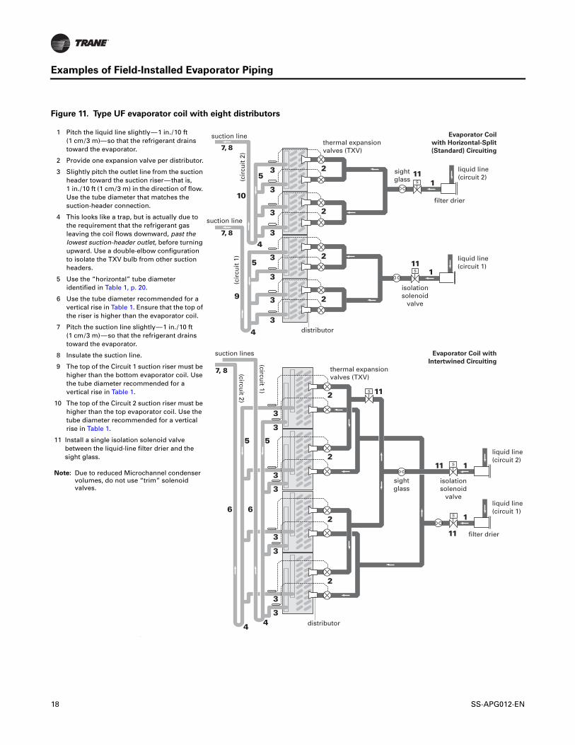
Figure 11. Type UF evaporator coil with eight distributors
‘
liquid line(circuit 1)
thermal expansionvalves (TXV)
distributor
Evaporator Coil
with Horizontal-Split
(Standard) Circuiting
thermal expansionvalves (TXV)
distributor
Evaporator Coil with
Intertwined Circuiting(circuit 1)
(circuit 2)
filter drier
liquid line(circuit 2)
sightglass
suction line
(cir
cuit
1)
(cir
cuit
2)
suction line
liquid line(circuit 1)
filter drier
liquid line(circuit 2)
sightglass
suction lines
isolationsolenoid
valve
isolationsolenoid
valve
1 Pitch the liquid line slightly — 1 in. / 10 ft (1 cm / 3 m)— so that the refrigerant drains toward the evaporator.
2 Provide one expansion valve per distributor.
3 Slightly pitch the outlet line from the suction header toward the suction riser — that is, 1 in. / 10 ft (1 cm / 3 m) in the direction of flow. Use the tube diameter that matches the suction-header connection.
4 This looks like a trap, but is actually due to the requirement that the refrigerant gas leaving the coil flows downward, past the lowest suction-header outlet, before turning upward. Use a double-elbow configuration to isolate the TXV bulb from other suction headers.
5 Use the “horizontal” tube diameter identified in Table 1, p. 20.
6 Use the tube diameter recommended for a vertical rise in Table 1. Ensure that the top of the riser is higher than the evaporator coil.
7 Pitch the suction line slightly — 1 in. / 10 ft (1 cm / 3 m) — so that the refrigerant drains toward the evaporator.
8 Insulate the suction line.
9 The top of the Circuit 1 suction riser must be higher than the bottom evaporator coil. Use the tube diameter recommended for a vertical rise in Table 1.
10 The top of the Circuit 2 suction riser must be higher than the top evaporator coil. Use the tube diameter recommended for a vertical rise in Table 1.
11 Install a single isolation solenoid valve between the liquid-line filter drier and the sight glass.
Note: Due to reduced Microchannel condenser volumes, do not use “trim” solenoid valves.
18 SS-APG012-EN

Examples of Field-Installed Evaporator Piping
RAUJ With Braze Plate Chilled-Water Heat Exchanger
Figure 12. Evaporator (EVP) chiller, typical refrigerant piping (2 circuit system)
Figure 13. EVP chiller, typical water piping
GAUGE PORTS &SUPERHEAT ADJUSTMENT PORT
#1 SUCTION LINE
#2 SUCTION LINE
#1 LIQUID LINE
CHARGING PORT
EXPANSION VALVE
MOISTURE INDICATOR
SOLENOID VALVE(MIGRATION ONLY)
#2 LIQUID LINE
REQUIRES FIELDPROVIDED 1/2”X14 NPTESTAINLESS STEELOR PVC PLUG
FILTER DRIER
TXV for Remote Chiller
Piping between the TXV and chiller, a braze plate heat exchanger (BPHE), must be 8-12” long and the same size as BPHE inlet ID. Field supplied reducer(s) may be required at TXV. A bleed port valve is not required with brazed plate heat exchanger applications.
Note: If necessary, install reducers at the TXV outlet. Do not install reducers at the braze plate evaporator.
PIPE CONNECTIONS
WATER STRAINER (< 1 mm)
AIR VENTS
PRESSURE GAUGE
UNIONSVIBRATION ELIMINATORS
THERMOMETERS
GATE VALVES
RETURN LINE (INLET)(SEE NOTE 1)
SUPPLY LINE OUTLET
FLOW SWITCH
AIR VENTS
SHUTOFF VALVES
UNIONS
VIBRATION ELIMINATORS
BALANCING VALVE
GATE VALVES
SUPPLY LINE OUTLET
Notes:
1. Shutoff valves are required for evaporator servicing.
2. Evaporator is shown for illustration purposes only.
3. Water inlet and outlet diameter and dimensional locations depends on unit size.
4. Water connections at the evaporator are grooved.
5. Field supplied 1/2” x 14 NPTE stainless steel or PVC plug required.
6. Locate freezestat and discharge temperature sensors close to the water outlet.
7. Install drain with shutoff valve at low point in leaving piping before system valve.
SS-APG012-EN 19

Parts
Table 1. Component selection summary
UNIT RAUJC20 RAUJC25 RAUJC30 RAUJC40 RAUJC50 RAUJC60 RAUJC80 RAUJD100 RAUJD120
Refrigerant ckts 1 1 1 2 2 2 2 2 2
Minimum step (tons) 10 10 15 10 11.7 15 15 15 20
SUCTION LINE SUCTION LINE
Tube diameter (in.)
Horizontal (& drops) 1 5/8 2 1/8 2 1/8 1 5/8 2 1/8 2 1/8 2 1/8 2 5/8 2 5/8
Vertical (up) 1 5/8 1 5/8 2 1/8 1 5/8 1 5/8 2 1/8 2 1/8 2 1/8 2 1/8
Filter shell 1/ckt DHY01086 FLR06122 FLR06122 DHY01086 FLR06122 FLR06122 FLR06123 FLR06124 FLR06124
Filter core per shell ELM03572 ELM03572 ELM03572 ELM03572 ELM03572 ELM03572 ELM03572 ELM03572 ELM03572
Access port 3/ckt(a)
(a) Valve body VAL01483, valve core COR00006, valve cap CAP00072
Schraeder valve w/core
Schraeder valve w/core
Schraeder valve w/core
Schraeder valve w/core
Schraeder valve w/core
Schraeder valve w/core
Schraeder valve w/core
Schraeder valve w/core
Schraeder valve w/core
Frostat™ control KIT01387 KIT01387 KIT01387 KIT01387 KIT01387 KIT01387 KIT01387 KIT01387 KIT01387
Ball valve 2/ckt (in.) VAL09077 VAL09078 VAL09078 VAL09077 VAL09078 VAL09078 VAL09078 VAL06647 VAL06647
LIQUID LINE LIQUID LINE
Tube diameter (in.) 5/8 7/8 7/8 5/8 7/8 7/8 1 1/8 1 1/8 1 1/8
Filter shell 1/ckt(b)
(b) 7/8” connection size
DHY01263 DHY01263 DHY01263 DHY01263 DHY01263 DHY01263 DHY01151 DHY01151 DHY01151
Filter core per shell COR00102 COR00102 COR00102 COR00102 COR00102 COR00102 COR00102 (QTY 2)
COR00102 (QTY 2)
COR00102 (QTY 2)
Solenoid valve, coil 1/ckt(c)
(c) For outdoor application, request junction box conduit boss, NEMA 4 watertight.
VAL09133COL01884
VAL09133COL01884
VAL09100COL01884
VAL09133COL01884
VAL09133COL01884
VAL09100COL01884
VAL09135COL01884
VAL09135COL01884
VAL09485COL12786
Sight glass 1/ckt GLS00830 GLS00831 GLS00831 GLS00830 GLS00831 GLS00831 GLS00832 GLS00832 GLS00832
Access port 2/ckt(a)Schraeder valve w/
core
Schraeder valve w/core
Schraeder valve w/core
Schraeder valve w/core
Schraeder valve w/core
Schraeder valve w/core
Schraeder valve w/core
Schraeder valve w/core
Schraeder valve w/core
Ball valve 2/ckt (in.) VAL07197 VAL07198 VAL07198 VAL07197 VAL07198 VAL07198 VAL07337 VAL07337 VAL07337
RAUJC20 RAUJC25 RAUJC30 RAUJC40 RAUJC50 RAUJC60 RAUJC80 RAUJD100 RAUJD120
20 SS-APG012-EN

Parts
Table 2. Expansion valves for 20-60T MCHE (30% bleed)
Table 3. Expansion valves for 80-120T MCHE (15% bleed)
Refrigerant Manufacturer Tonnage Range Model Number Trane PartR-410A Sporlan 2-3 ERZE-1-1/2-ZGA (BP/30) VAL10487
R-410A Sporlan 2.5-3.5 ERZE-2-ZGA (BP/30) VAL10488
R-410A Sporlan 3.5-5 ERZE-3-ZGA (BP/30) VAL10489
R-410A Sporlan 4.5-7 ERZE-4-ZGA (BP/30) VAL10490
R-410A Sporlan 6-8.5 ERZE-5-ZGA (BP/30) VAL10491
R-410A Sporlan 7-10 ERZE-6-ZGA (BP/30) VAL10492
R-410A Sporlan 8-13.5 ERZE-8-ZGA (BP/30) VAL10493
R-410A Sporlan 11-17.5 ERZE-12-1/2-ZGA (BP/30) VAL10494
R-410A Sporlan 14-21.5 ERZE-15-ZGA (BP/30) VAL10495
R-410A Sporlan 17-28.5 OZE-20-ZGA (BP/30) VAL10496
R-410A Sporlan 22-30 OZE-25-ZGA (BP/40) VAL10497
Refrigerant Manufacturer Tonnage Range Model Number Trane PartR-410A Sporlan 2-2.5 ERZE-1-1/2-ZGA (BP/15) N/A
R-410A Sporlan 2.5-3 ERZE-2-ZGA (BP/15) N/A
R-410A Sporlan 3-4.5 ERZE-3-ZGA (BP/15) N/A
R-410A Sporlan 4-6 ERZE-4-ZGA (BP/15) N/A
R-410A Sporlan 5-7.5 ERZE-5-ZGA (BP/15) VAL10579
R-410A Sporlan 6-9 ERZE-6-ZGA (BP/15) VAL10580
R-410A Sporlan 7-12 ERZE-8-ZGA (BP/15) VAL10581
R-410A Sporlan 9.5-15.5 ERZE-12-1/2-ZGA (BP/15) VAL10582
R-410A Sporlan 12.5-19 ERZE-15-ZGA (BP/15) VAL10583
R-410A Sporlan 15-25 OZE-20-ZGA (BP/15) VAL10584
R-410A Sporlan 19.5-30 OZE-25-ZGA (BP/15) VAL10585
R-410A Sporlan 23.5-45 OZE-35-ZGA (BP/15) VAL10586
R-410A Sporlan 35-68 OZE-50-ZGA (BP/15) VAL10587
R-410A Sporlan 52.5-70 OZE-60-ZGA (BP/15) VAL10588
SS-APG012-EN 21
Parts
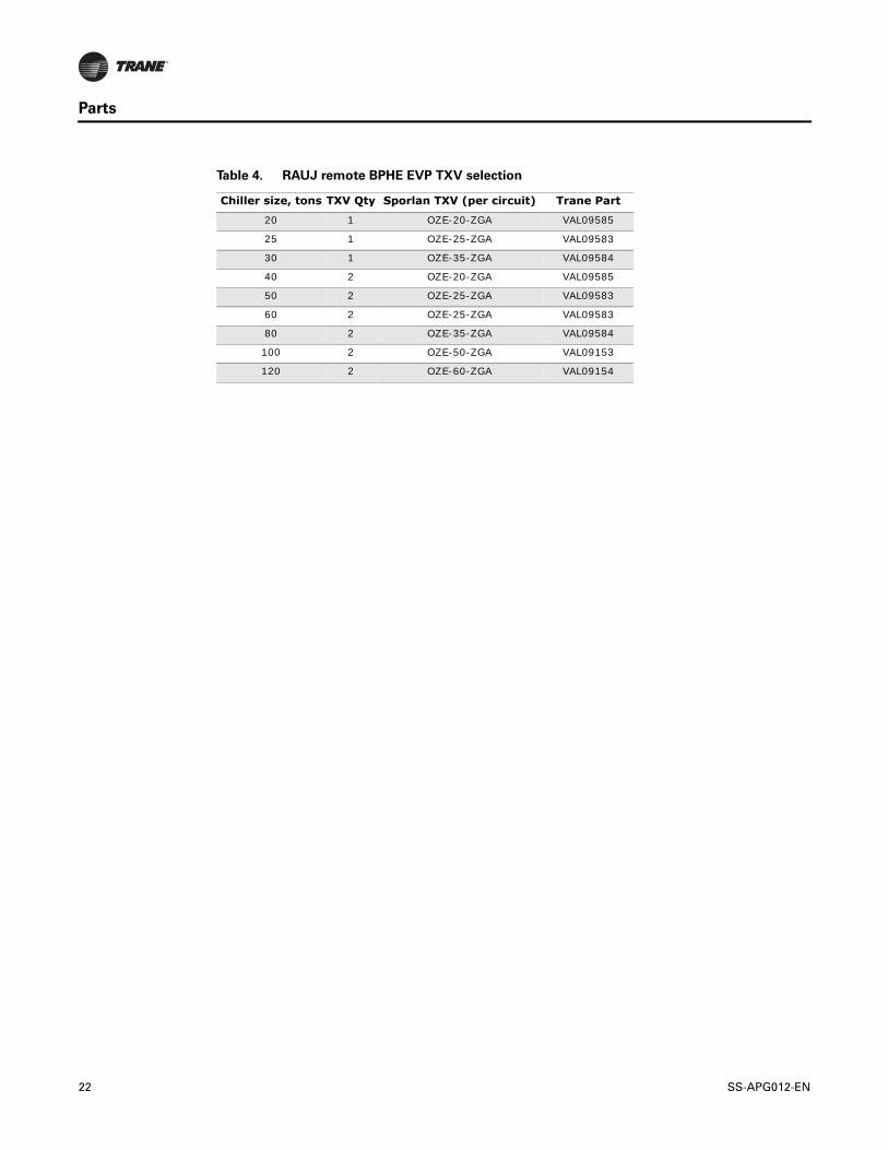
Table 4. RAUJ remote BPHE EVP TXV selection
Chiller size, tons TXV Qty Sporlan TXV (per circuit) Trane Part
20 1 OZE-20-ZGA VAL09585
25 1 OZE-25-ZGA VAL09583
30 1 OZE-35-ZGA VAL09584
40 2 OZE-20-ZGA VAL09585
50 2 OZE-25-ZGA VAL09583
60 2 OZE-25-ZGA VAL09583
80 2 OZE-35-ZGA VAL09584
100 2 OZE-50-ZGA VAL09153
120 2 OZE-60-ZGA VAL09154
22 SS-APG012-EN


Trane optimizes the performance of homes and buildings around the world. A business of Ingersoll Rand, the leader in creating and sustaining safe, comfortable and energy efficient environments, Trane offers a broad portfolio of advanced controls and HVAC systems, comprehensive building services, and parts. For more information, visit www.Trane.com.
Trane has a policy of continuous product and product data improvement and reserves the right to change design and specifications without notice.
We are committed to using environmentally
conscious print practices that reduce waste.
© 2012 Trane All rights reserved
SS-APG012-EN 19 Mar 2012