Embed Size (px)
Citation preview

http://support.automation.siemens.com/WW/view/en/103528928
Application Description � 11/2014
Communication of a SIMATICMV400, S7-1500 and a HMIvia PROFINET/IESIMATIC MV400
Warranty and Liability
MV400 PROFINET/IEEntry ID: 103528928, V1.0, 11/2014 2
ãS
iem
ens
AG
2014
All
right
sre
serv
ed
Warranty and LiabilityNote The Application Examples are not binding and do not claim to be complete with
regard to configuration, equipment or any contingencies. The ApplicationExamples do not represent customer-specific solutions. They are only intendedto provide support for typical applications. You are responsible for the correctoperation of the described products. These Application Examples do not relieveyou of the responsibility of safely and professionally using, installing, operatingand servicing equipment. When using these Application Examples, yourecognize that we cannot be made liable for any damage/claims beyond theliability clause described. We reserve the right to make changes to theseApplication Examples at any time and without prior notice. If there are anydeviations between the recommendations provided in this Application Exampleand other Siemens publications – e.g. catalogs – the contents of the otherdocuments have priority.
We do not accept any liability for the information contained in this document.Any claims against us – based on whatever legal reason – resulting from the use ofthe examples, information, programs, engineering and performance data etc.,described in this Application Example will be excluded. Such an exclusion will notapply in the case of mandatory liability, e.g. under the German Product Liability Act(“Produkthaftungsgesetz”), in case of intent, gross negligence, or injury of life, bodyor health, guarantee for the quality of a product, fraudulent concealment of adeficiency or breach of a condition which goes to the root of the contract(“wesentliche Vertragspflichten”). The compensation for damages due to a breachof a fundamental contractual obligation is, however, limited to the foreseeabledamage, typical for the type of contract, except in the event of intent or grossnegligence or injury to life, body or health. The above provisions do not imply achange of the burden of proof to your detriment.Any form of duplication or distribution of these Application Examples or excerptshereof is prohibited without the expressed consent of Siemens Industry Sector.
Securityinforma-
tion
Siemens provides products and solutions with industrial security functions thatsupport the secure operation of plants, solutions, machines, equipment and/ornetworks. They are important components in a holistic industrial securityconcept. With this in mind, Siemens’ products and solutions undergo continuousdevelopment. Siemens recommends strongly that you regularly check forproduct updates.
For the secure operation of Siemens products and solutions, it is necessary totake suitable preventive action (e.g. cell protection concept) and integrate eachcomponent into a holistic, state-of-the-art industrial security concept. Third-partyproducts that may be in use should also be considered. For more informationabout industrial security, visit http://www.siemens.com/industrialsecurity.
To stay informed about product updates as they occur, sign up for a product-specific newsletter. For more information, visithttp://support.automation.siemens.com.
Table of Contents
MV400 PROFINET/IEEntry ID: 103528928, V1.0, 11/2014 3
ãS
iem
ens
AG
2014
All
right
sre
serv
ed
Table of ContentsWarranty and Liability .............................................................................................. 21 Task................................................................................................................. 4
1.1 Overview ........................................................................................... 41.2 Requirements .................................................................................... 5
2 Solution........................................................................................................... 6
2.1 Overview ........................................................................................... 62.2 Description of the core functionality .................................................... 82.3 Hardware and software components ................................................ 102.3.1 Validity ............................................................................................ 102.3.2 Components used ........................................................................... 10
3 Mode of Operation ........................................................................................ 123.1 General principle of operation .......................................................... 123.2 Control program............................................................................... 133.2.1 Program details of FB “MV_Write_Requests” ................................... 143.2.2 Program details of FB “MV_Read_Requests” ................................... 153.2.3 Program details of FC “Trigger_Simulation” ..................................... 173.2.4 Program details of the library blocks ................................................ 173.3 Functionality of user-defined interface .............................................. 183.4 Functionality of the remote client ...................................................... 18
4 Configuration and Settings .......................................................................... 20
4.1 STEP 7 V13..................................................................................... 204.2 Setup support of the code reader ..................................................... 23
5 Installation and Commissioning .................................................................. 27
5.1 Installing the hardware ..................................................................... 275.2 Installing the software ...................................................................... 285.3 Installing the STEP 7 V13 project ..................................................... 285.4 Commissioning ................................................................................ 28
6 Operating the Application ............................................................................ 32
6.1 Menu navigation of the HMI user interface ....................................... 326.2 Menu item “Overview” ...................................................................... 346.3 Menu item “Code reader” ................................................................. 356.3.1 Reset/program change .................................................................... 376.3.2 Changing match string ..................................................................... 386.3.3 Displaying diagnostic screens .......................................................... 396.3.4 User-defined interface ..................................................................... 396.3.5 Saving/loading device configuration ................................................. 41
7 Further Tips and Tricks ................................................................................ 428 References .................................................................................................... 439 History .......................................................................................................... 43
1 Task
MV400 PROFINET/IEEntry ID: 103528928, V1.0, 11/2014 4
ãS
iem
ens
AG
2014
All
right
sre
serv
ed
1 Task1.1 Overview
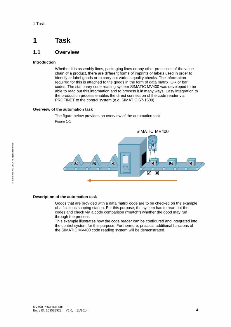
IntroductionWhether it is assembly lines, packaging lines or any other processes of the valuechain of a product, there are different forms of imprints or labels used in order toidentify or label goods or to carry out various quality checks. The informationrequired for this is attached to the goods in the form of data matrix, QR or barcodes. The stationary code reading system SIMATIC MV400 was developed to beable to read out this information and to process it in many ways. Easy integration tothe production process enables the direct connection of the code reader viaPROFINET to the control system (e.g. SIMATIC S7-1500).
Overview of the automation taskThe figure below provides an overview of the automation task.Figure 1-1
SIMATIC MV400
þ ý
Description of the automation taskGoods that are provided with a data matrix code are to be checked on the exampleof a fictitious shaping station. For this purpose, the system has to read out thecodes and check via a code comparison (“match”) whether the good may runthrough the process.This example illustrates how the code reader can be configured and integrated intothe control system for this purpose. Furthermore, practical additional functions ofthe SIMATIC MV400 code reading system will be demonstrated.
1 Task
MV400 PROFINET/IEEntry ID: 103528928, V1.0, 11/2014 5
ãS
iem
ens
AG
2014
All
right
sre
serv
ed
1.2 Requirements
The application requires the following prerequisites:· The code reader is to be connected via PROFINET to a SIMATIC S7-1500
controller which controls the example scenario.· The user-defined interface (CustomGUI) of the coder reader which can be
called via web browser, is to be demonstrated and explained (call fromSIMATIC HMI).
· The configuration of the code reader is to be loaded/saved via web browser(remote client function).
· The example scenario is to be operated and monitored from the user viaSIMATIC HMI.
· Diagnostic screens of the code reader are to be visualized via HMI.
2 Solution
MV400 PROFINET/IEEntry ID: 103528928, V1.0, 11/2014 6
ãS
iem
ens
AG
2014
All
right
sre
serv
ed
2 Solution2.1 Overview
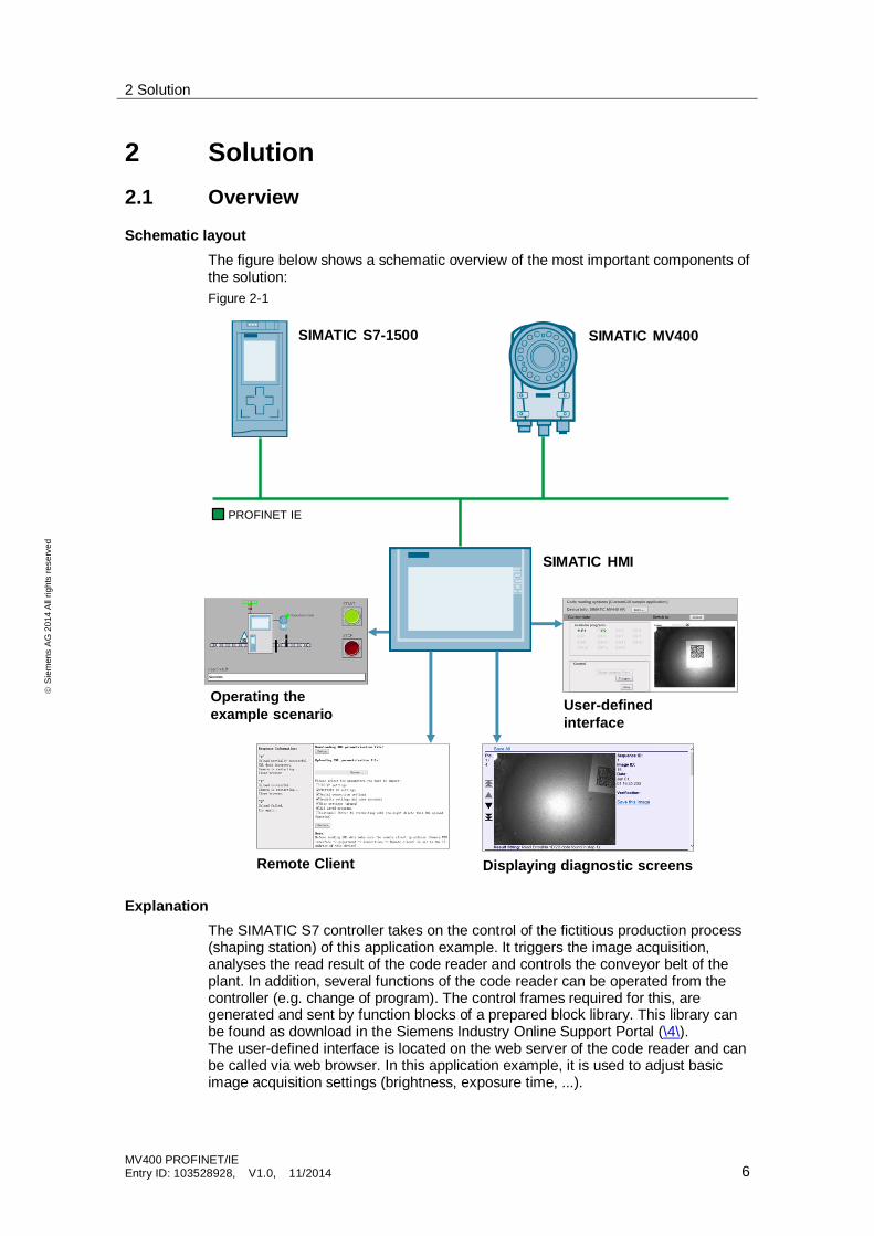
Schematic layoutThe figure below shows a schematic overview of the most important components ofthe solution:Figure 2-1
PROFINET IE
SIMATIC S7-1500
SIMATIC HMI
SIMATIC MV400
Operating theexample scenario User-defined
interface
Remote Client Displaying diagnostic screens
ExplanationThe SIMATIC S7 controller takes on the control of the fictitious production process(shaping station) of this application example. It triggers the image acquisition,analyses the read result of the code reader and controls the conveyor belt of theplant. In addition, several functions of the code reader can be operated from thecontroller (e.g. change of program). The control frames required for this, aregenerated and sent by function blocks of a prepared block library. This library canbe found as download in the Siemens Industry Online Support Portal (\4\).The user-defined interface is located on the web server of the code reader and canbe called via web browser. In this application example, it is used to adjust basicimage acquisition settings (brightness, exposure time, ...).
2 Solution
MV400 PROFINET/IEEntry ID: 103528928, V1.0, 11/2014 7
ãS
iem
ens
AG
2014
All
right
sre
serv
ed
The remote client, based on a HTTP interface, is implemented via an HMTLcommand in this application. The web page that has been created for this purposeis also located on the web server of the code reader and can be called via webbrowser.In order to display diagnostic screens of the coder reader, there is a web pagewhich is especially optimized for HMIs on the reader and that can be viewed viaweb browser.Two prepared programs for image acquisition are supplied with this application forthe code reader:· Program 1: Reading of data matrix code (DMC) and comparison with
predefined match string· Program 2: Reading of bar codes without match string comparison
AdvantagesThe solution presented here offers you the following advantages:· Easy and fast integration into your SIMATIC S7 automation system· Communication of the S7 CPU via simple interface to the code reader
(prepared block library)· Flexible expandability, for example, of read code types· The SIMATIC MV400 code reading system can be conveniently configured via
web interface (setup support)· Demonstration of different innovative functions of the SIMATIC MV400 code
reading system on a practical example
DelimitationThis application does not contain a description of:· Handling of STEP 7 and WinCC in TIA Portal· Industrial Ethernet and PROFINET· Basics of SIMATIC automation systemsBasic knowledge of these topics is assumed.
2 Solution
MV400 PROFINET/IEEntry ID: 103528928, V1.0, 11/2014 8
ãS
iem
ens
AG
2014
All
right
sre
serv
ed
2.2 Description of the core functionality
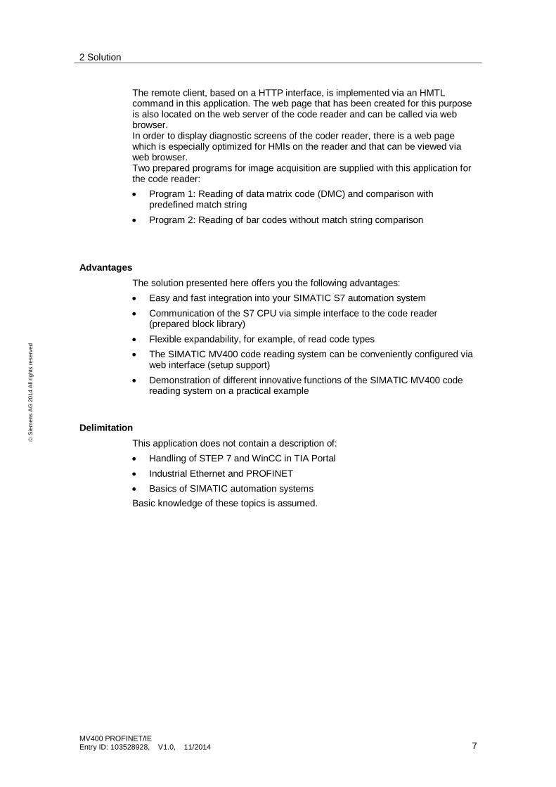
Overview and description of the user interfaceFigure 2-2
Table 2-1
No. Description of the control elements
1. Plant START2. Plant STOP3. Status display of the plant (traffic light)4. Status display of the code reader5. Output of the read result6. Menu navigation7. Conveyor belt (simulation)8. Light barrier (simulation)9. Change language
Note The light barrier is only simulated in this application example and is not made upof real hardware.
1
2
3 4
5
6
9
78
2 Solution
MV400 PROFINET/IEEntry ID: 103528928, V1.0, 11/2014 9
ãS
iem
ens
AG
2014
All
right
sre
serv
ed
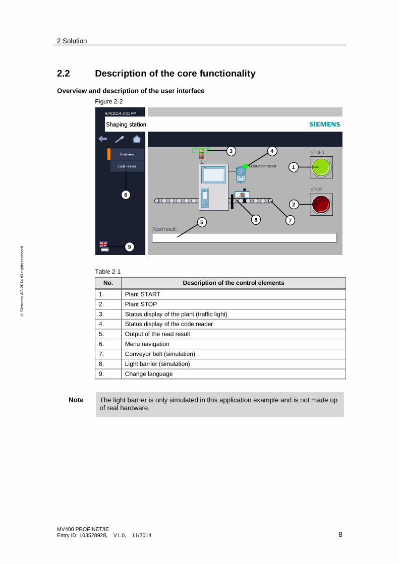
Sequence of the core functionalityTable 2-2
No. Explanation
1. Once the plant is up and running, the coder reader has to be switched toprocessing mode with a program number specification (see chap. 6.3.1). Thestatus display of the code reader (4) lights up green.
2. The production process can only be started via the START button (1). The buttonand the status display of the plant (3) lights up green.
3. The simulated conveyor belt (7) starts to shift and moves goods (rectangles) inthe direction of the shaping station.
4. When a good passes the simulated light barrier (8), the S7 controller sends acommand frame for image acquisition to the code reader.
5. The code reader takes a picture and analyzes the result.The analysis depends on the program number specification.Program 1:
· Analysis after read error· Analysis after match error
Program 2:· Analysis after read error
6. Once the images have been analyzed, the code reader generates the resultstring:
· Read OK: The result string includes the read code.· Read NOK: The result string includes the error message belonging
to the error that occurred (see step 5).7. The result string is sent to the S7 controller and displayed in the read result field
of the HMI (5).8. The S7 controller analyses the result string. If the string includes an error
message, the entire plant goes to STOP. The status display of the plant (3) andthe STOP button lights up red.If there is no error message in the result string, the goods can go through theshaping process and leave as triangles.
9. The whole process starts automatically again from the beginning.
Note If the plant goes to STOP in step 8, the user can continue the process bymanually entering a code into the read result field (5).
By clicking the START button (1) again, the user can let the process start againfrom the beginning.
2 Solution
MV400 PROFINET/IEEntry ID: 103528928, V1.0, 11/2014 10
ãS
iem
ens
AG
2014
All
right
sre
serv
ed
2.3 Hardware and software components
2.3.1 Validity
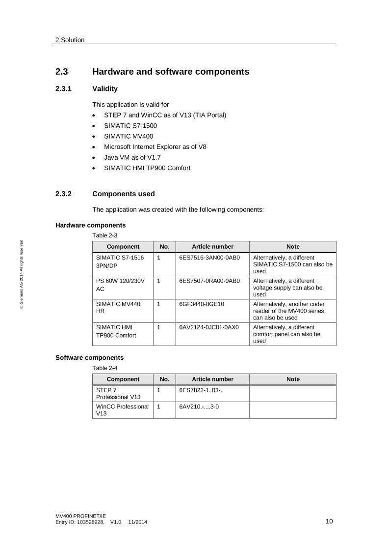
This application is valid for· STEP 7 and WinCC as of V13 (TIA Portal)· SIMATIC S7-1500· SIMATIC MV400· Microsoft Internet Explorer as of V8· Java VM as of V1.7· SIMATIC HMI TP900 Comfort
2.3.2 Components used
The application was created with the following components:
Hardware componentsTable 2-3
Component No. Article number Note
SIMATIC S7-15163PN/DP
1 6ES7516-3AN00-0AB0 Alternatively, a differentSIMATIC S7-1500 can also beused
PS 60W 120/230VAC
1 6ES7507-0RA00-0AB0 Alternatively, a differentvoltage supply can also beused
SIMATIC MV440HR
1 6GF3440-0GE10 Alternatively, another coderreader of the MV400 seriescan also be used
SIMATIC HMITP900 Comfort
1 6AV2124-0JC01-0AX0 Alternatively, a differentcomfort panel can also beused
Software componentsTable 2-4
Component No. Article number Note
STEP 7Professional V13
1 6ES7822-1..03-..
WinCC ProfessionalV13
1 6AV210.-....3-0
2 Solution
MV400 PROFINET/IEEntry ID: 103528928, V1.0, 11/2014 11
ãS
iem
ens
AG
2014
All
right
sre
serv
ed
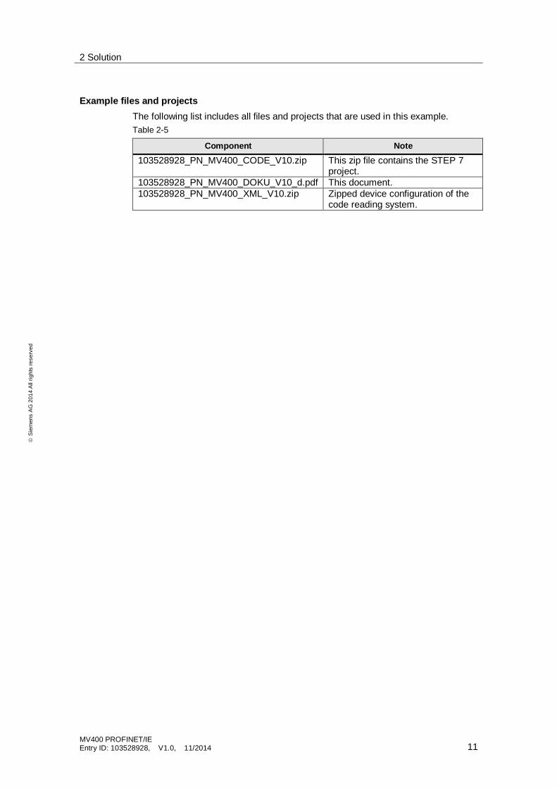
Example files and projectsThe following list includes all files and projects that are used in this example.Table 2-5
Component Note103528928_PN_MV400_CODE_V10.zip This zip file contains the STEP 7
project.103528928_PN_MV400_DOKU_V10_d.pdf This document.103528928_PN_MV400_XML_V10.zip Zipped device configuration of the
code reading system.
3 Mode of Operation
MV400 PROFINET/IEEntry ID: 103528928, V1.0, 11/2014 12
ãS
iem
ens
AG
2014
All
right
sre
serv
ed
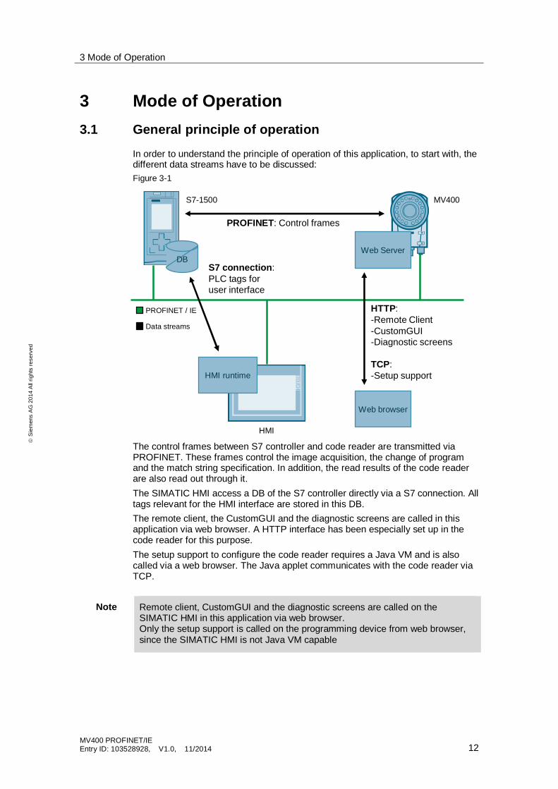
3 Mode of Operation3.1 General principle of operation
In order to understand the principle of operation of this application, to start with, thedifferent data streams have to be discussed:Figure 3-1
DB
PROFINET / IE
Data streams
PROFINET: Control frames
HMI runtime
Web browser
S7 connection:PLC tags foruser interface
HTTP:-Remote Client-CustomGUI-Diagnostic screens
TCP:-Setup support
Web Server
S7-1500 MV400
HMI
The control frames between S7 controller and code reader are transmitted viaPROFINET. These frames control the image acquisition, the change of programand the match string specification. In addition, the read results of the code readerare also read out through it.The SIMATIC HMI access a DB of the S7 controller directly via a S7 connection. Alltags relevant for the HMI interface are stored in this DB.The remote client, the CustomGUI and the diagnostic screens are called in thisapplication via web browser. A HTTP interface has been especially set up in thecode reader for this purpose.The setup support to configure the code reader requires a Java VM and is alsocalled via a web browser. The Java applet communicates with the code reader viaTCP.
Note Remote client, CustomGUI and the diagnostic screens are called on theSIMATIC HMI in this application via web browser.Only the setup support is called on the programming device from web browser,since the SIMATIC HMI is not Java VM capable
3 Mode of Operation
MV400 PROFINET/IEEntry ID: 103528928, V1.0, 11/2014 13
ãS
iem
ens
AG
2014
All
right
sre
serv
ed
3.2 Control program
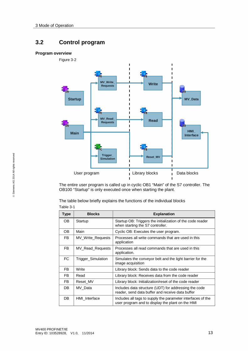
Program overviewFigure 3-2
Startup
MV_Write_Requests
MV_Read_Requests
Trigger_Simulation
Main
Reset_MV
Read
Write
MV_Data
HMI_Interface
User program Library blocks Data blocks
The entire user program is called up in cyclic OB1 “Main” of the S7 controller. TheOB100 “Startup” is only executed once when starting the plant.
The table below briefly explains the functions of the individual blocksTable 3-1
Type Blocks Explanation
OB Startup Startup OB: Triggers the initialization of the code readerwhen starting the S7 controller.
OB Main Cyclic OB: Executes the user program.FB MV_Write_Requests Processes all write commands that are used in this
applicationFB MV_Read_Requests Processes all read commands that are used in this
application.FC Trigger_Simulation Simulates the conveyor belt and the light barrier for the
image acquisitionFB Write Library block: Sends data to the code readerFB Read Library block: Receives data from the code readerFB Reset_MV Library block: Initialization/reset of the code readerDB MV_Data Includes data structure (UDT) for addressing the code
reader, send data buffer and receive data bufferDB HMI_Interface Includes all tags to supply the parameter interfaces of the
user program and to display the plant on the HMI
3 Mode of Operation
MV400 PROFINET/IEEntry ID: 103528928, V1.0, 11/2014 14
ãS
iem
ens
AG
2014
All
right
sre
serv
ed
3.2.1 Program details of FB “MV_Write_Requests”
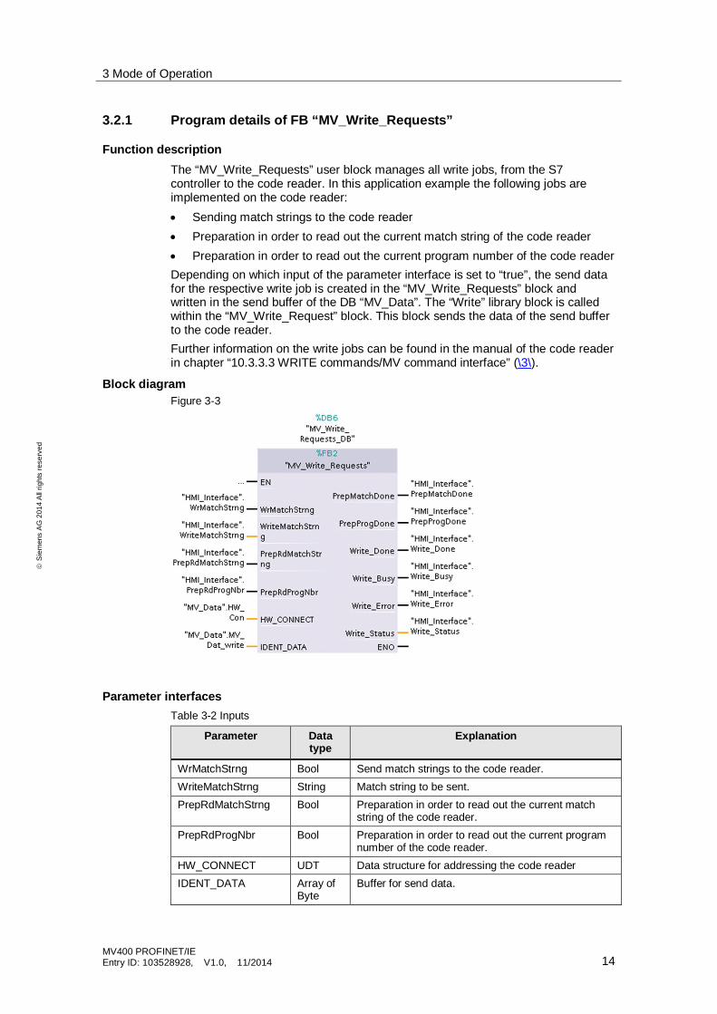
Function descriptionThe “MV_Write_Requests” user block manages all write jobs, from the S7controller to the code reader. In this application example the following jobs areimplemented on the code reader:· Sending match strings to the code reader· Preparation in order to read out the current match string of the code reader· Preparation in order to read out the current program number of the code readerDepending on which input of the parameter interface is set to “true”, the send datafor the respective write job is created in the “MV_Write_Requests” block andwritten in the send buffer of the DB “MV_Data”. The “Write” library block is calledwithin the “MV_Write_Request” block. This block sends the data of the send bufferto the code reader.Further information on the write jobs can be found in the manual of the code readerin chapter “10.3.3.3 WRITE commands/MV command interface” (\3\).
Block diagramFigure 3-3
Parameter interfacesTable 3-2 Inputs
Parameter Datatype
Explanation
WrMatchStrng Bool Send match strings to the code reader.WriteMatchStrng String Match string to be sent.PrepRdMatchStrng Bool Preparation in order to read out the current match
string of the code reader.PrepRdProgNbr Bool Preparation in order to read out the current program
number of the code reader.HW_CONNECT UDT Data structure for addressing the code readerIDENT_DATA Array of
ByteBuffer for send data.
3 Mode of Operation
MV400 PROFINET/IEEntry ID: 103528928, V1.0, 11/2014 15
ãS
iem
ens
AG
2014
All
right
sre
serv
ed
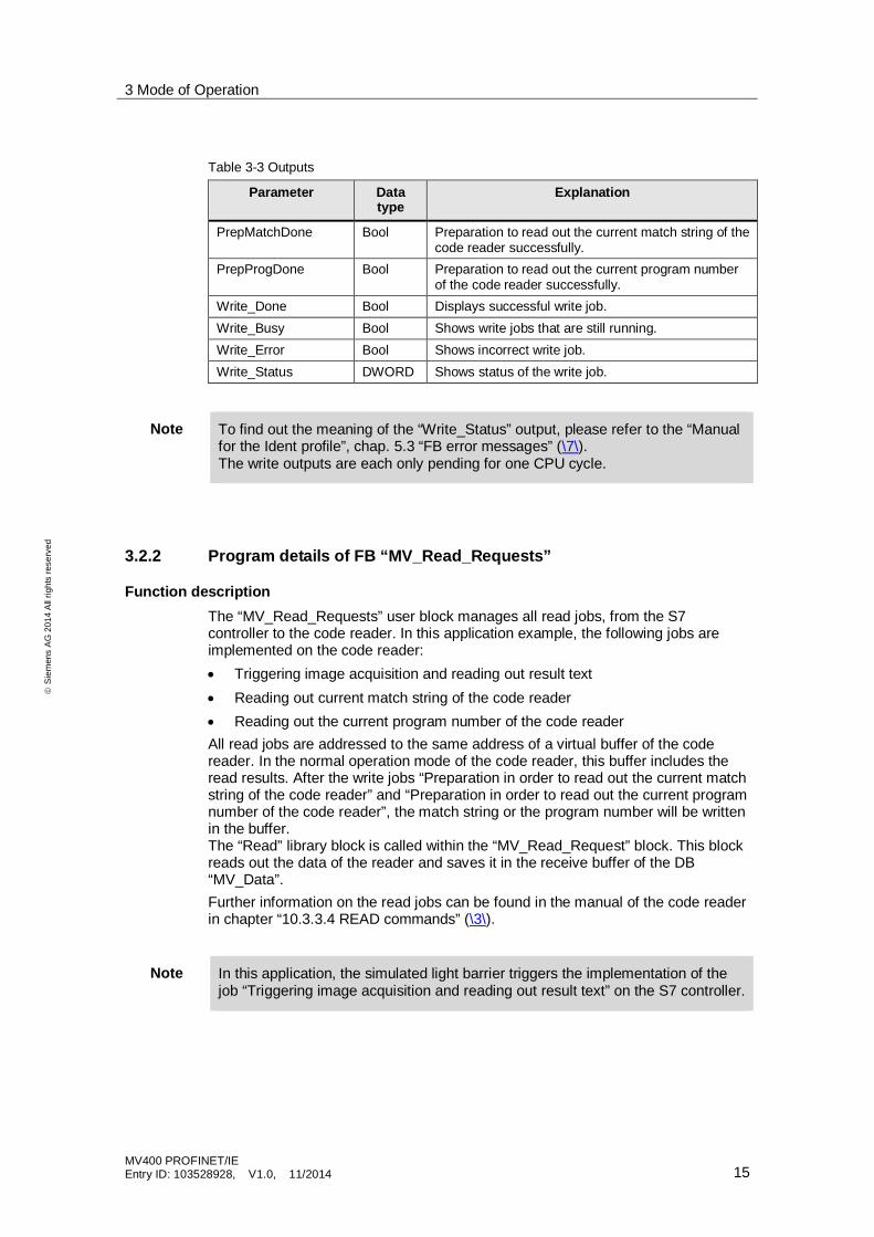
Table 3-3 Outputs
Parameter Datatype
Explanation
PrepMatchDone Bool Preparation to read out the current match string of thecode reader successfully.
PrepProgDone Bool Preparation to read out the current program numberof the code reader successfully.
Write_Done Bool Displays successful write job.Write_Busy Bool Shows write jobs that are still running.Write_Error Bool Shows incorrect write job.Write_Status DWORD Shows status of the write job.
Note To find out the meaning of the “Write_Status” output, please refer to the “Manualfor the Ident profile”, chap. 5.3 “FB error messages” (\7\).The write outputs are each only pending for one CPU cycle.
3.2.2 Program details of FB “MV_Read_Requests”
Function descriptionThe “MV_Read_Requests” user block manages all read jobs, from the S7controller to the code reader. In this application example, the following jobs areimplemented on the code reader:· Triggering image acquisition and reading out result text· Reading out current match string of the code reader· Reading out the current program number of the code readerAll read jobs are addressed to the same address of a virtual buffer of the codereader. In the normal operation mode of the code reader, this buffer includes theread results. After the write jobs “Preparation in order to read out the current matchstring of the code reader” and “Preparation in order to read out the current programnumber of the code reader”, the match string or the program number will be writtenin the buffer.The “Read” library block is called within the “MV_Read_Request” block. This blockreads out the data of the reader and saves it in the receive buffer of the DB“MV_Data”.Further information on the read jobs can be found in the manual of the code readerin chapter “10.3.3.4 READ commands” (\3\).
Note In this application, the simulated light barrier triggers the implementation of thejob “Triggering image acquisition and reading out result text” on the S7 controller.
3 Mode of Operation
MV400 PROFINET/IEEntry ID: 103528928, V1.0, 11/2014 16
ãS
iem
ens
AG
2014
All
right
sre
serv
ed
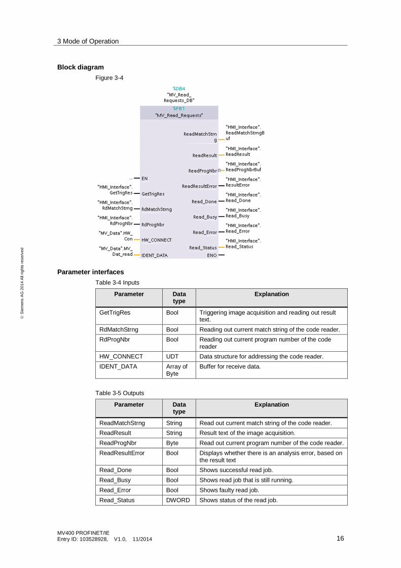
Block diagramFigure 3-4
Parameter interfacesTable 3-4 Inputs
Parameter Datatype
Explanation
GetTrigRes Bool Triggering image acquisition and reading out resulttext.
RdMatchStrng Bool Reading out current match string of the code reader.RdProgNbr Bool Reading out current program number of the code
readerHW_CONNECT UDT Data structure for addressing the code reader.IDENT_DATA Array of
ByteBuffer for receive data.
Table 3-5 Outputs
Parameter Datatype
Explanation
ReadMatchStrng String Read out current match string of the code reader.ReadResult String Result text of the image acquisition.ReadProgNbr Byte Read out current program number of the code reader.ReadResultError Bool Displays whether there is an analysis error, based on
the result textRead_Done Bool Shows successful read job.Read_Busy Bool Shows read job that is still running.Read_Error Bool Shows faulty read job.Read_Status DWORD Shows status of the read job.
3 Mode of Operation
MV400 PROFINET/IEEntry ID: 103528928, V1.0, 11/2014 17
ãS
iem
ens
AG
2014
All
right
sre
serv
ed
Note To find out the meaning of the “Read_Status” output, please refer to the “Manualfor the Ident profile”, chap. 5.3 “FB error messages” (\7\).The read outputs are each only pending for one CPU cycle.
3.2.3 Program details of FC “Trigger_Simulation”
Function descriptionThe “Trigger_Simulation” function simulates the conveyor belt of the fictitiousshaping station and the light barrier for triggering the image acquisition(“MV_Read_Requests”, “GetTrigRes” parameter interface, see chapter 3.2.2).
3.2.4 Program details of the library blocks
Function descriptionThe PROFINET communication between S7 controller and the code reader ismanaged by the function blocks of the “Identification” block library. In thisapplication example, the blocks “Reset_MV”, “Read” and “Write” of the library areused.For further information on the library blocks, see \7\.
3 Mode of Operation
MV400 PROFINET/IEEntry ID: 103528928, V1.0, 11/2014 18
ãS
iem
ens
AG
2014
All
right
sre
serv
ed
3.3 Functionality of user-defined interface
General explanationsThe user-defined interface (CustomGUI) is a web interface that can be freelyadjusted by the user. It can be called via web browser and is stored in a web serverof the code reader. Via the setup support, the CustomGUI can be downloaded oruploaded (“Maintain” > “CustomGUI”). The files have to be stored there in form of aZIP archive.The CustomGUI of this application example is only an adjustment of the exemplaryinterface, supplied with the code reader, in order to demonstrate this CustomGUIon a SIMATIC HMI.The adjustments refer to the restricted display options of the internet browser of theSIMATIC HMI touch panel. The CustomGUI included, consists of HTML and Javascript elements.
InterfaceThe CustomGUI is located on the web server of the code reader as static webpage. In order for the web page or other programs to be able to poll information ofthe code reader, there is a CGI (Common Gateway Interface) on the server pagewhich can be addressed via HTTP commands.
Note A precise description of the CGI is not part of this application.
FunctionsThe setting options have been realized via the user-defined interface in thisapplication:· Information on the code reading device used· Changing camera program· Starting/stopping processing mode· Changing acquisition settings (exposure time, brightness, format, ...)The example interface which is supplied with this application can be called inhttp://<IP address or the reader>/cgui/CGUISample.html.
3.4 Functionality of the remote client
The remote client is only used to load the configuration of the code reader or tosave it.In this application example, the remote client function of the code reading systemMV400 is used by another HTML page stored on the web server of the codereader. The solution introduced here is optimal for HMIs with restricted operatingsystem, since the methods HTTP post and GET are integrated in the HTMLstandard and therefore only require a standard Internet browser.Just as for the CustomGUI, there is a CGI for the remote client function which canbe triggered via HTTP commands.The remote client example which is included supplied with this application can becalled in http://<IP address or the reader>/cgui/POSTSample.html.

3 Mode of Operation
MV400 PROFINET/IEEntry ID: 103528928, V1.0, 11/2014 19
ãS
iem
ens
AG
2014
All
right
sre
serv
ed
Note In order to be able to use the remote client function introduced here, the deviceconfiguration included this application has to be loaded into the code reader. Theremote client IP address stored in the code reader has to correspond to that ofthe HMI.
For further information, please refer to the “SINAMICS MV420/ MV440 operatinginstruction” in chap. “10.8 Remote client” (\3\).
4 Configuration and Settings
MV400 PROFINET/IEEntry ID: 103528928, V1.0, 11/2014 20
ãS
iem
ens
AG
2014
All
right
sre
serv
ed
4 Configuration and Settings
Note If you are using alternative hardware, please follow the instructions in thischapter.If the hardware is identical these settings do not have to be made, they arealready included in the project. Continue with chap. 5.
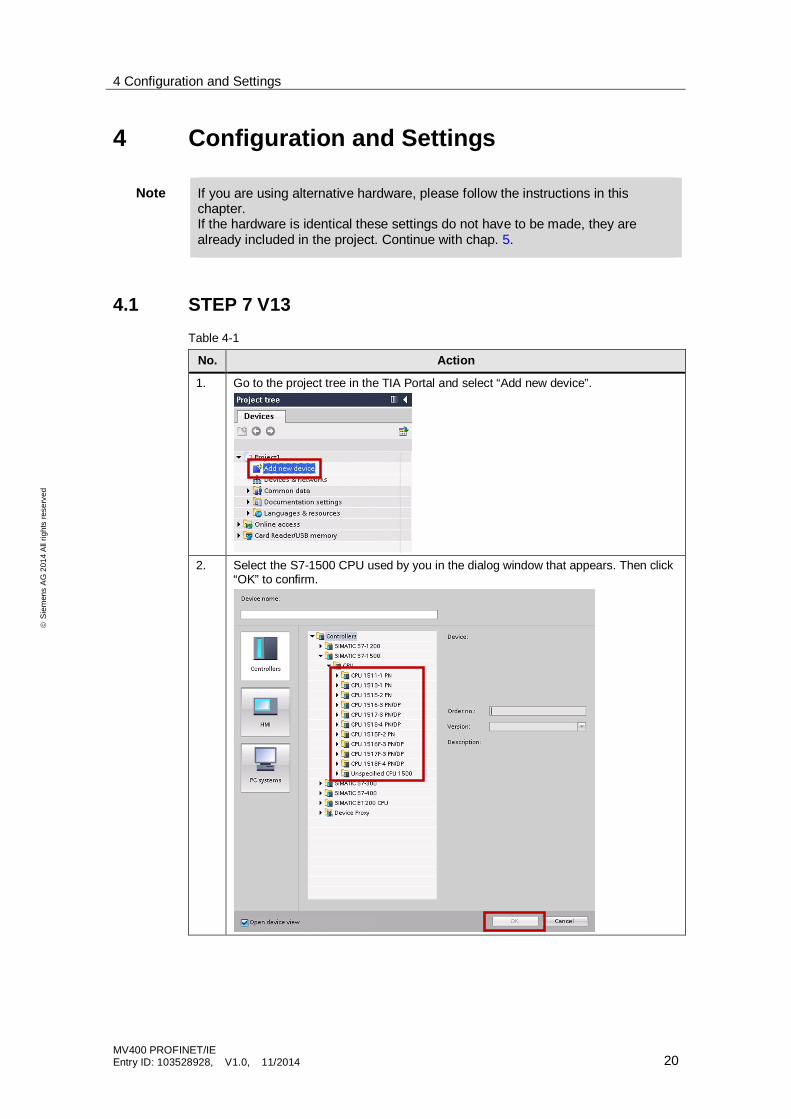
4.1 STEP 7 V13Table 4-1
No. Action
1. Go to the project tree in the TIA Portal and select “Add new device”.
2. Select the S7-1500 CPU used by you in the dialog window that appears. Then click“OK” to confirm.
4 Configuration and Settings
MV400 PROFINET/IEEntry ID: 103528928, V1.0, 11/2014 21
ãS
iem
ens
AG
2014
All
right
sre
serv
ed
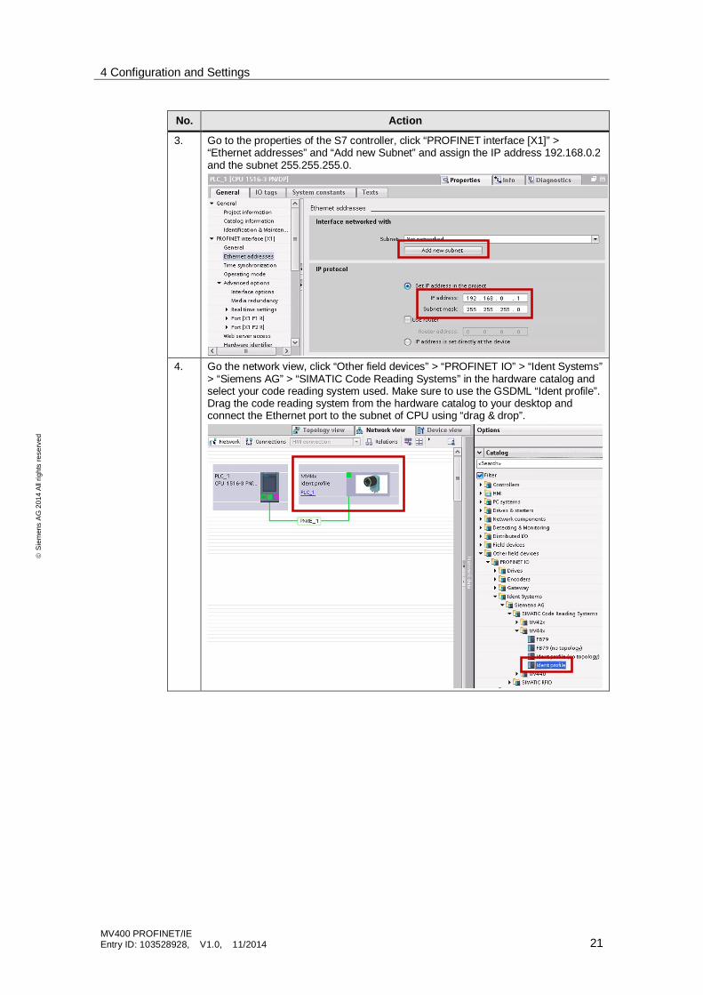
No. Action
3. Go to the properties of the S7 controller, click “PROFINET interface [X1]” >“Ethernet addresses” and “Add new Subnet” and assign the IP address 192.168.0.2and the subnet 255.255.255.0.
4. Go the network view, click “Other field devices” > “PROFINET IO” > “Ident Systems”> “Siemens AG” > “SIMATIC Code Reading Systems” in the hardware catalog andselect your code reading system used. Make sure to use the GSDML “Ident profile”.Drag the code reading system from the hardware catalog to your desktop andconnect the Ethernet port to the subnet of CPU using “drag & drop”.
4 Configuration and Settings
MV400 PROFINET/IEEntry ID: 103528928, V1.0, 11/2014 22
ãS
iem
ens
AG
2014
All
right
sre
serv
ed
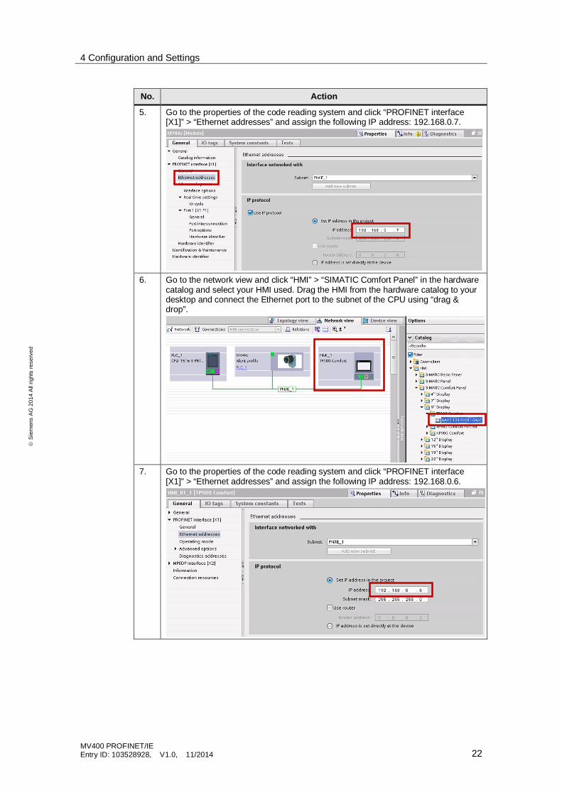
No. Action
5. Go to the properties of the code reading system and click “PROFINET interface[X1]” > “Ethernet addresses” and assign the following IP address: 192.168.0.7.
6. Go to the network view and click “HMI” > “SIMATIC Comfort Panel” in the hardwarecatalog and select your HMI used. Drag the HMI from the hardware catalog to yourdesktop and connect the Ethernet port to the subnet of the CPU using “drag &drop”.
7. Go to the properties of the code reading system and click “PROFINET interface[X1]” > “Ethernet addresses” and assign the following IP address: 192.168.0.6.
4 Configuration and Settings
MV400 PROFINET/IEEntry ID: 103528928, V1.0, 11/2014 23
ãS
iem
ens
AG
2014
All
right
sre
serv
ed
No. Action
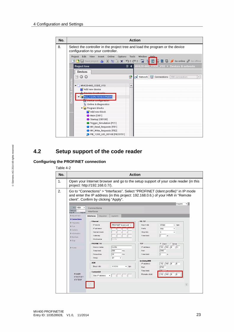
8. Select the controller in the project tree and load the program or the deviceconfiguration to your controller.
4.2 Setup support of the code reader
Configuring the PROFINET connectionTable 4-2
No. Action
1. Open your Internet browser and go to the setup support of your code reader (in thisproject: http://192.168.0.7/).
2. Go to “Connections” > “Interfaces”. Select “PROFINET (Ident profile)” in IP modeand enter the IP address (in this project: 192.168.0.6.) of your HMI in “Remoteclient”. Confirm by clicking “Apply“.
4 Configuration and Settings
MV400 PROFINET/IEEntry ID: 103528928, V1.0, 11/2014 24
ãS
iem
ens
AG
2014
All
right
sre
serv
ed
No. Action
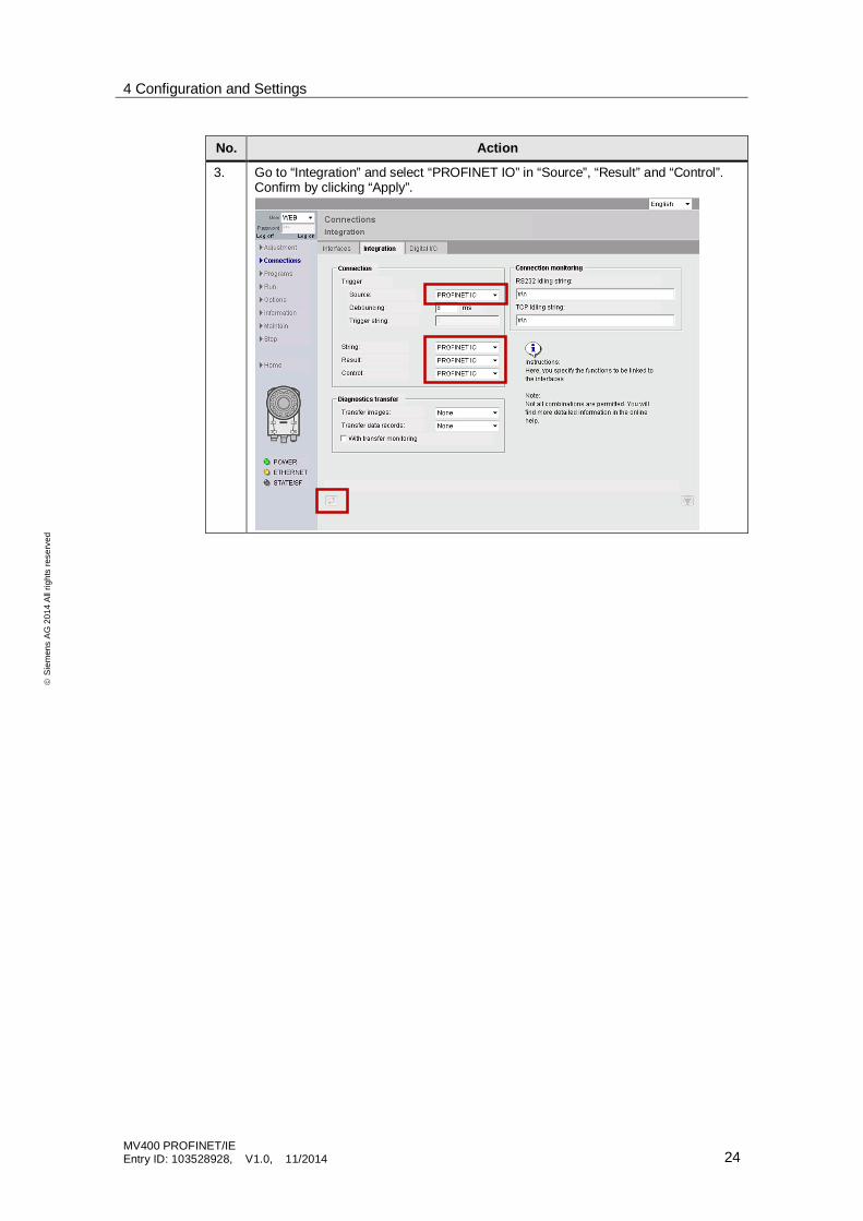
3. Go to “Integration” and select “PROFINET IO” in “Source”, “Result” and “Control”.Confirm by clicking “Apply”.
4 Configuration and Settings
MV400 PROFINET/IEEntry ID: 103528928, V1.0, 11/2014 25
ãS
iem
ens
AG
2014
All
right
sre
serv
ed
Creating programTable 4-3
No. Action
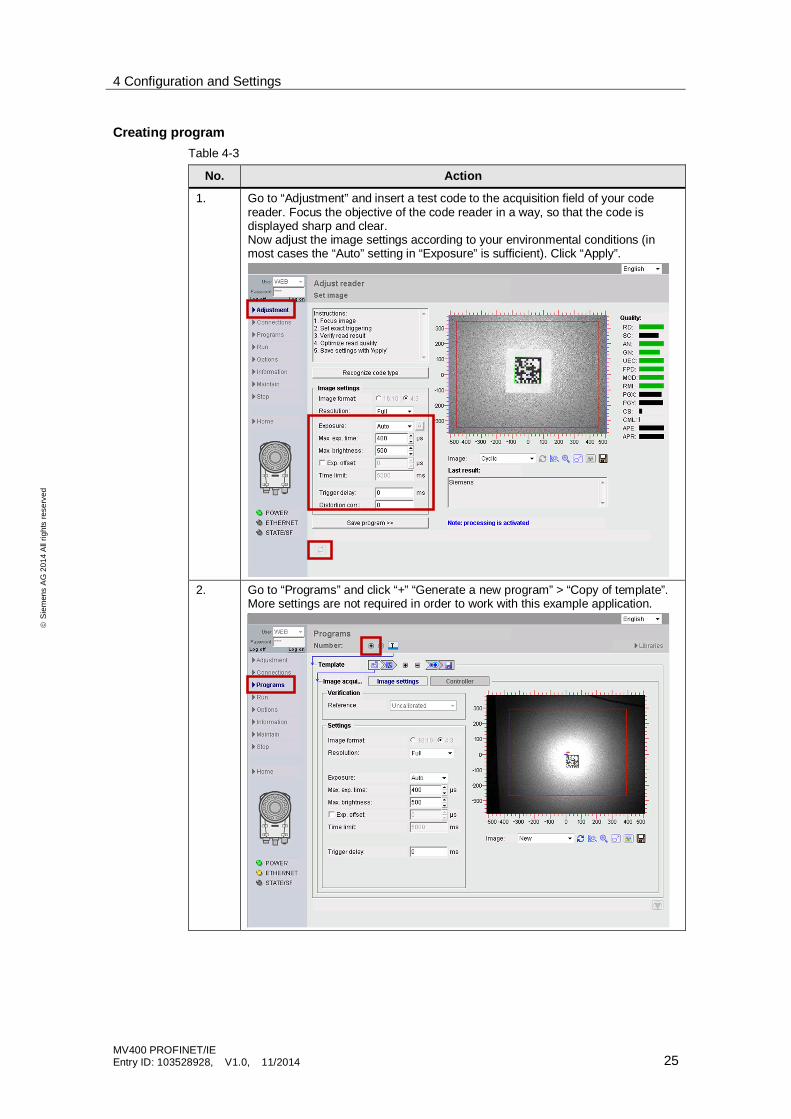
1. Go to “Adjustment” and insert a test code to the acquisition field of your codereader. Focus the objective of the code reader in a way, so that the code isdisplayed sharp and clear.Now adjust the image settings according to your environmental conditions (inmost cases the “Auto” setting in “Exposure” is sufficient). Click “Apply”.
2. Go to “Programs” and click “+” “Generate a new program” > “Copy of template”.More settings are not required in order to work with this example application.

4 Configuration and Settings
MV400 PROFINET/IEEntry ID: 103528928, V1.0, 11/2014 26
ãS
iem
ens
AG
2014
All
right
sre
serv
ed
No. Action
3. Go to “Save”, enter a name and a number click “Save now”. From the HMI youcan now start the processing mode of the code reader with the program numberspecified by you.
Note The program creation described here, only deals with the part required for thisapplication.For further information on the program creation, please refer to the “SINAMICSMV420/ MV440 operating instructions” (\3\).
5 Installation and Commissioning
MV400 PROFINET/IEEntry ID: 103528928, V1.0, 11/2014 27
ãS
iem
ens
AG
2014
All
right
sre
serv
ed
5 Installation and Commissioning
5.1 Installing the hardware
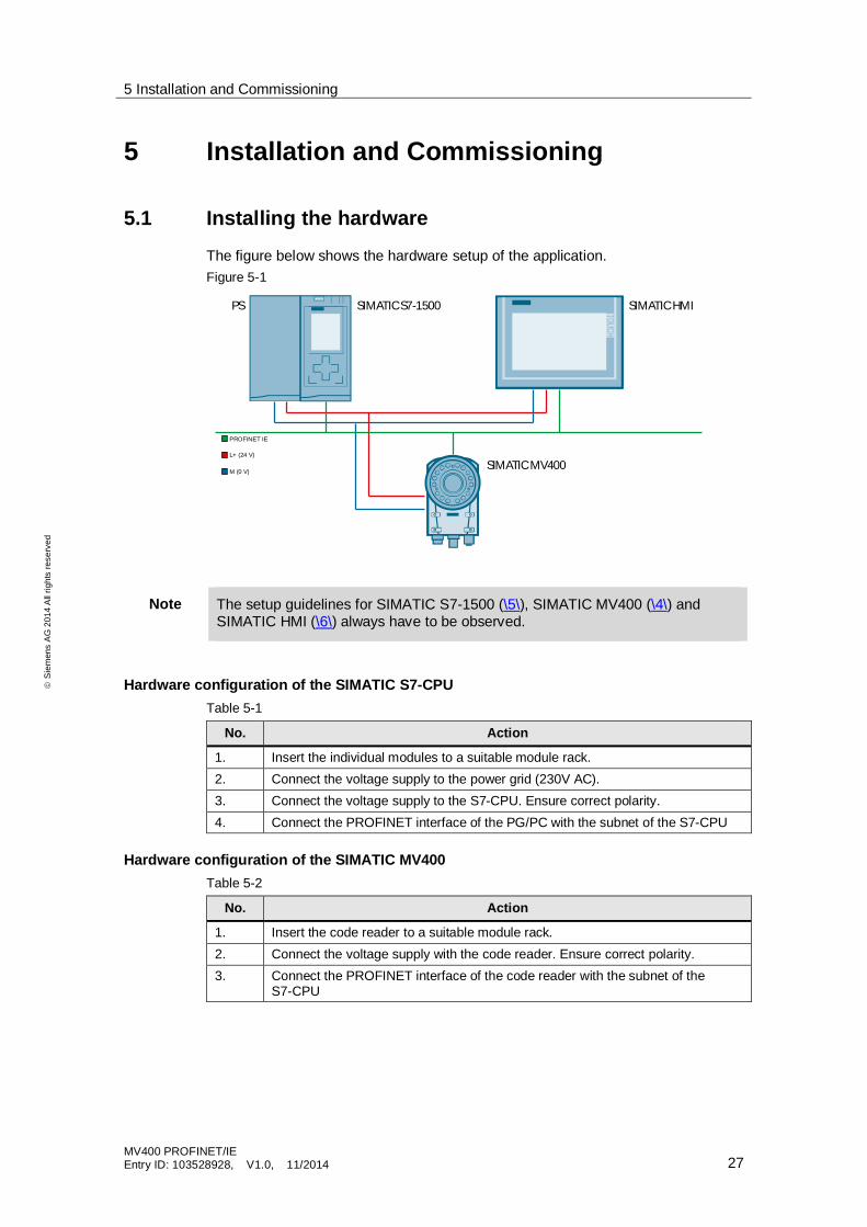
The figure below shows the hardware setup of the application.Figure 5-1
PROFINET IE
SIMATIC S7-1500 SIMATIC HMI
SIMATIC MV400M (0 V)
L+ (24 V)
PS
Note The setup guidelines for SIMATIC S7-1500 (\5\), SIMATIC MV400 (\4\) andSIMATIC HMI (\6\) always have to be observed.
Hardware configuration of the SIMATIC S7-CPUTable 5-1
No. Action
1. Insert the individual modules to a suitable module rack.2. Connect the voltage supply to the power grid (230V AC).3. Connect the voltage supply to the S7-CPU. Ensure correct polarity.4. Connect the PROFINET interface of the PG/PC with the subnet of the S7-CPU
Hardware configuration of the SIMATIC MV400Table 5-2
No. Action
1. Insert the code reader to a suitable module rack.2. Connect the voltage supply with the code reader. Ensure correct polarity.3. Connect the PROFINET interface of the code reader with the subnet of the
S7-CPU
5 Installation and Commissioning
MV400 PROFINET/IEEntry ID: 103528928, V1.0, 11/2014 28
ãS
iem
ens
AG
2014
All
right
sre
serv
ed
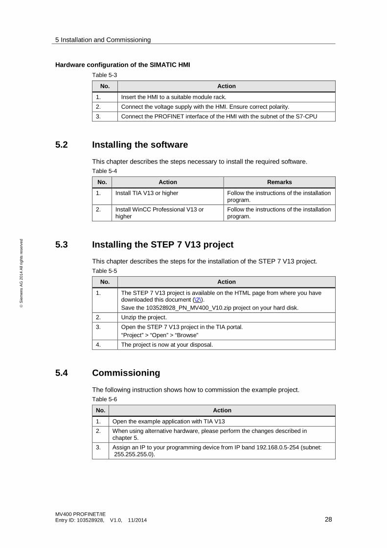
Hardware configuration of the SIMATIC HMITable 5-3
No. Action
1. Insert the HMI to a suitable module rack.2. Connect the voltage supply with the HMI. Ensure correct polarity.3. Connect the PROFINET interface of the HMI with the subnet of the S7-CPU
5.2 Installing the software
This chapter describes the steps necessary to install the required software.Table 5-4
No. Action Remarks
1. Install TIA V13 or higher Follow the instructions of the installationprogram.
2. Install WinCC Professional V13 orhigher
Follow the instructions of the installationprogram.
5.3 Installing the STEP 7 V13 project
This chapter describes the steps for the installation of the STEP 7 V13 project.Table 5-5
No. Action
1. The STEP 7 V13 project is available on the HTML page from where you havedownloaded this document (\2\).Save the 103528928_PN_MV400_V10.zip project on your hard disk.
2. Unzip the project.3. Open the STEP 7 V13 project in the TIA portal.
“Project” > “Open” > “Browse”4. The project is now at your disposal.
5.4 Commissioning
The following instruction shows how to commission the example project.Table 5-6
No. Action
1. Open the example application with TIA V132. When using alternative hardware, please perform the changes described in
chapter 5.3. Assign an IP to your programming device from IP band 192.168.0.5-254 (subnet:
255.255.255.0).
5 Installation and Commissioning
MV400 PROFINET/IEEntry ID: 103528928, V1.0, 11/2014 29
ãS
iem
ens
AG
2014
All
right
sre
serv
ed
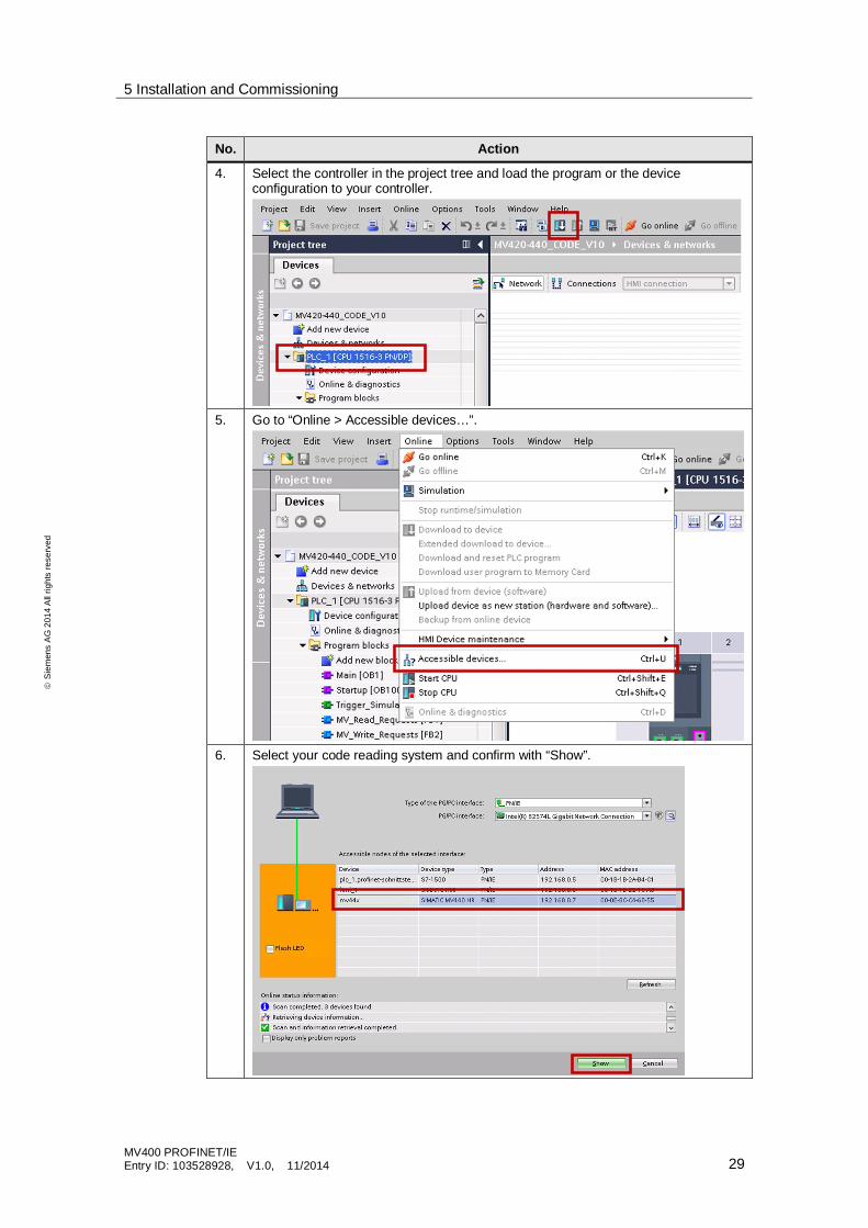
No. Action
4. Select the controller in the project tree and load the program or the deviceconfiguration to your controller.
5. Go to “Online > Accessible devices…”.
6. Select your code reading system and confirm with “Show”.
5 Installation and Commissioning
MV400 PROFINET/IEEntry ID: 103528928, V1.0, 11/2014 30
ãS
iem
ens
AG
2014
All
right
sre
serv
ed
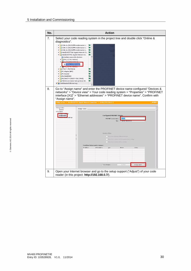
No. Action
7. Select your code reading system in the project tree and double click “Online &diagnostics”.
8. Go to “Assign name” and enter the PROFINET device name configured “Devices &networks” > “Device view” > Your code reading system > “Properties” > “PROFINETinterface [X1]” > “Ethernet addresses” > “PROFINET device name”. Confirm with“Assign name”.
9. Open your Internet browser and go to the setup support (“Adjust”) of your codereader (in this project: http://192.168.0.7/).
5 Installation and Commissioning
MV400 PROFINET/IEEntry ID: 103528928, V1.0, 11/2014 31
ãS
iem
ens
AG
2014
All
right
sre
serv
ed
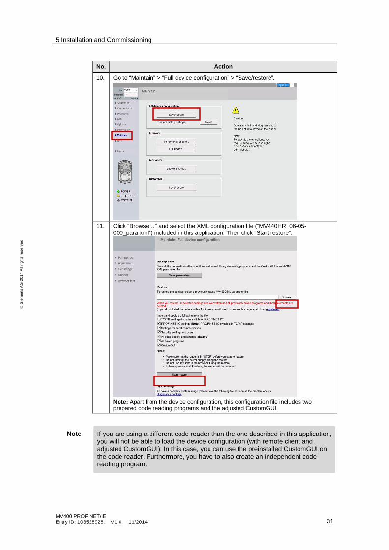
No. Action
10. Go to “Maintain” > “Full device configuration” > “Save/restore”.
11. Click “Browse…” and select the XML configuration file (“MV440HR_06-05-000_para.xml”) included in this application. Then click “Start restore”.
Note: Apart from the device configuration, this configuration file includes twoprepared code reading programs and the adjusted CustomGUI.
Note If you are using a different code reader than the one described in this application,you will not be able to load the device configuration (with remote client andadjusted CustomGUI). In this case, you can use the preinstalled CustomGUI onthe code reader. Furthermore, you have to also create an independent codereading program.
6 Operating the Application
MV400 PROFINET/IEEntry ID: 103528928, V1.0, 11/2014 32
ãS
iem
ens
AG
2014
All
right
sre
serv
ed
6 Operating the Application
6.1 Menu navigation of the HMI user interface
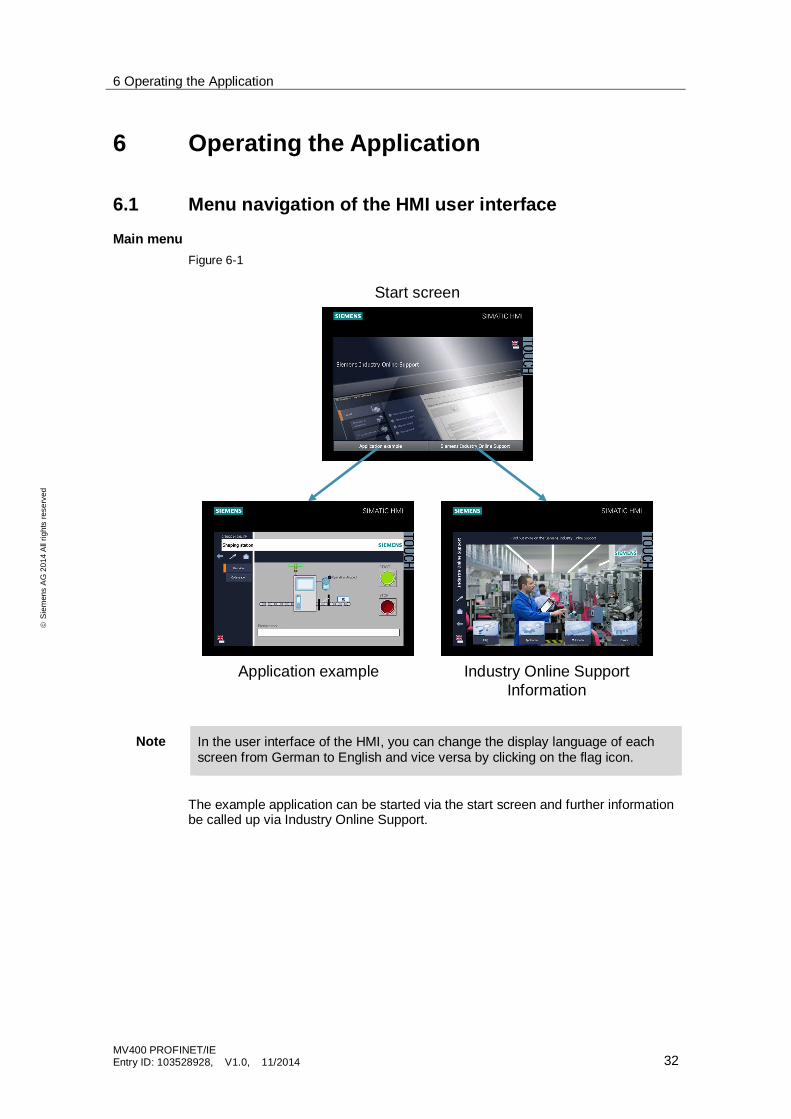
Main menuFigure 6-1
Start screen
Application example Industry Online SupportInformation
Note In the user interface of the HMI, you can change the display language of eachscreen from German to English and vice versa by clicking on the flag icon.
The example application can be started via the start screen and further informationbe called up via Industry Online Support.
6 Operating the Application
MV400 PROFINET/IEEntry ID: 103528928, V1.0, 11/2014 33
ãS
iem
ens
AG
2014
All
right
sre
serv
ed
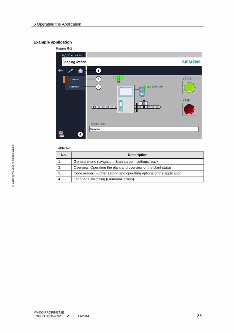
Example applicationFigure 6-2
Table 6-1
No. Description
1. General menu navigation: Start screen, settings, back2. Overview: Operating the plant and overview of the plant status3. Code reader: Further setting and operating options of the application4. Language switching (German/English)
1
2
3
4
6 Operating the Application
MV400 PROFINET/IEEntry ID: 103528928, V1.0, 11/2014 34
ãS
iem
ens
AG
2014
All
right
sre
serv
ed
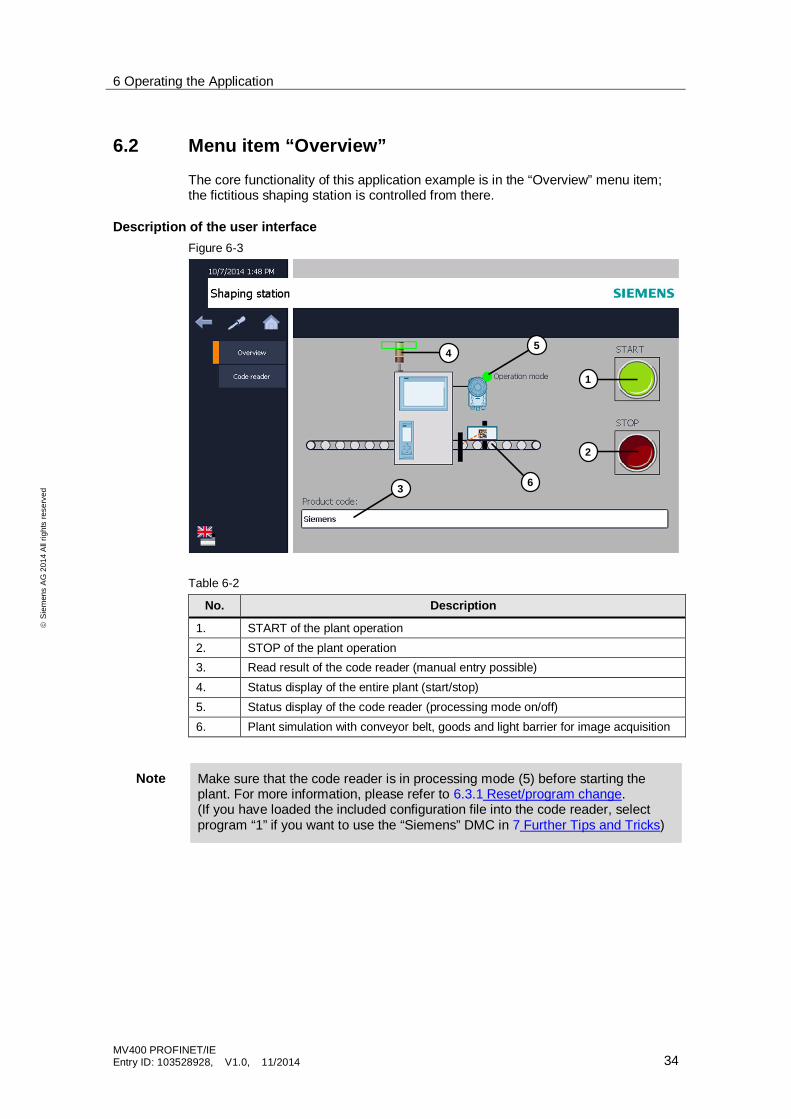
6.2 Menu item “Overview”
The core functionality of this application example is in the “Overview” menu item;the fictitious shaping station is controlled from there.
Description of the user interfaceFigure 6-3
Table 6-2
No. Description
1. START of the plant operation2. STOP of the plant operation3. Read result of the code reader (manual entry possible)4. Status display of the entire plant (start/stop)5. Status display of the code reader (processing mode on/off)6. Plant simulation with conveyor belt, goods and light barrier for image acquisition
Note Make sure that the code reader is in processing mode (5) before starting theplant. For more information, please refer to 6.3.1 Reset/program change.(If you have loaded the included configuration file into the code reader, selectprogram “1” if you want to use the “Siemens” DMC in 7 Further Tips and Tricks)
1
2
3
45
6
6 Operating the Application
MV400 PROFINET/IEEntry ID: 103528928, V1.0, 11/2014 35
ãS
iem
ens
AG
2014
All
right
sre
serv
ed
Operating the plantTable 6-3
No. Action
1. Place the code under the code reader (for program1: DMC; for program 2: barcode; see chap. 7). Start the plant (1).
2. The conveyor belt moves the goods (rectangle) with the printed data matrix codein the direction of the shaping converter station. If goods pass the light barrier,the image acquisition of the code reader (6) is triggered automatically.
3. The captured image is analyzed and output in the result string (3).4. If there is no error (“Match error” or “Read error”), the goods can pass the
shaping station and leave it as triangles.If an error occurs (match error), the error is displayed instead of the result text (3)and the plant goes to STOP.
5. As long as the plant in ON, the procedure will start again automatically.
Note If an error occurs the plant automatically goes to STOP.
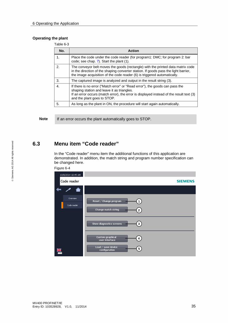
6.3 Menu item “Code reader”
In the “Code reader” menu item the additional functions of this application aredemonstrated. In addition, the match string and program number specification canbe changed here.Figure 6-4
1
2
3
4
5
6 Operating the Application
MV400 PROFINET/IEEntry ID: 103528928, V1.0, 11/2014 36
ãS
iem
ens
AG
2014
All
right
sre
serv
ed
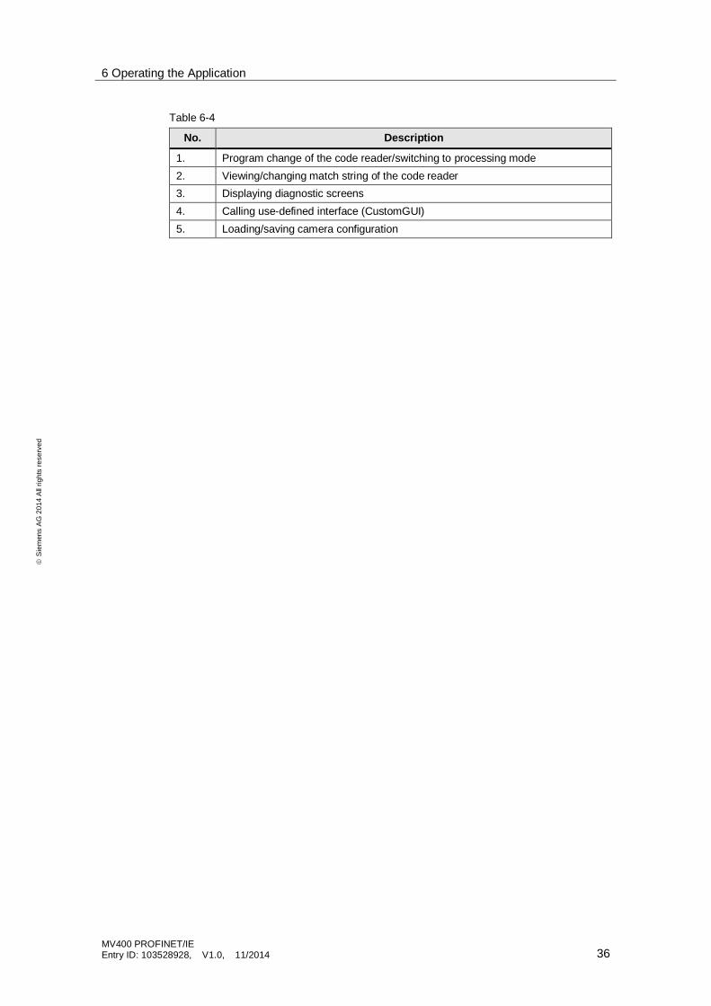
Table 6-4
No. Description
1. Program change of the code reader/switching to processing mode2. Viewing/changing match string of the code reader3. Displaying diagnostic screens4. Calling use-defined interface (CustomGUI)5. Loading/saving camera configuration
6 Operating the Application
MV400 PROFINET/IEEntry ID: 103528928, V1.0, 11/2014 37
ãS
iem
ens
AG
2014
All
right
sre
serv
ed
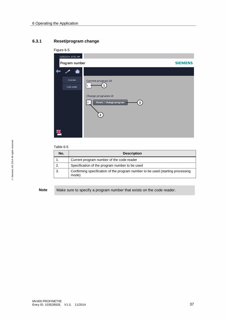
6.3.1 Reset/program change
Figure 6-5
Table 6-5
No. Description
1. Current program number of the code reader2. Specification of the program number to be used3. Confirming specification of the program number to be used (starting processing
mode)
Note Make sure to specify a program number that exists on the code reader.
1
2
3
6 Operating the Application
MV400 PROFINET/IEEntry ID: 103528928, V1.0, 11/2014 38
ãS
iem
ens
AG
2014
All
right
sre
serv
ed
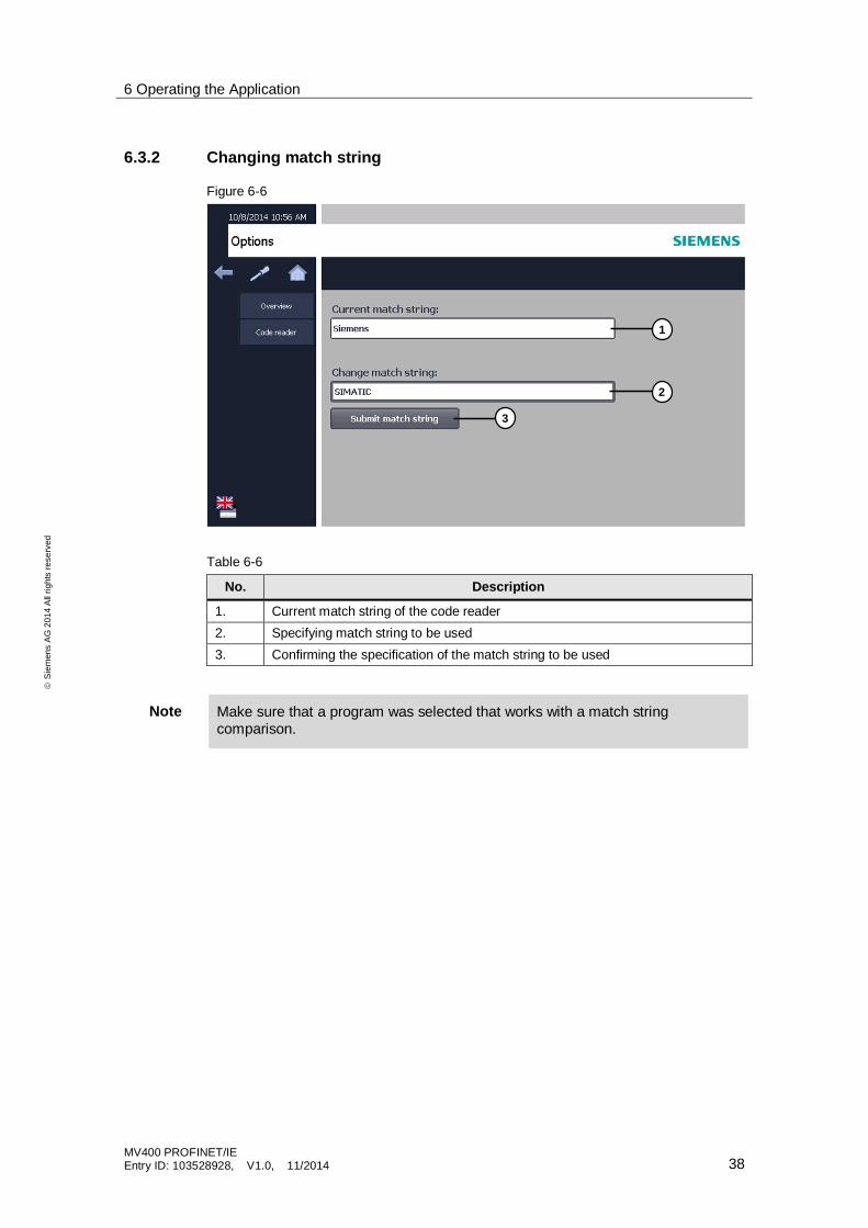
6.3.2 Changing match string
Figure 6-6
Table 6-6
No. Description
1. Current match string of the code reader2. Specifying match string to be used3. Confirming the specification of the match string to be used
Note Make sure that a program was selected that works with a match stringcomparison.
1
2
3
6 Operating the Application
MV400 PROFINET/IEEntry ID: 103528928, V1.0, 11/2014 39
ãS
iem
ens
AG
2014
All
right
sre
serv
ed
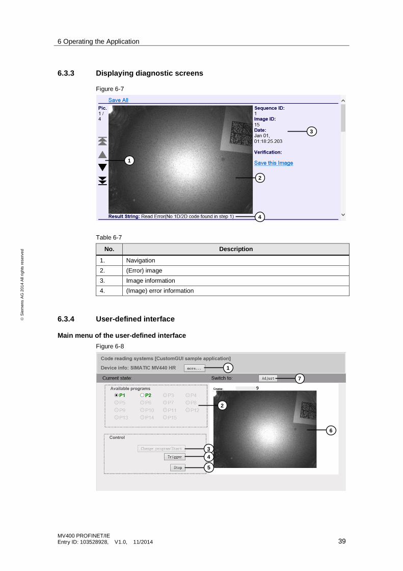
6.3.3 Displaying diagnostic screens
Figure 6-7
Table 6-7
No. Description
1. Navigation2. (Error) image3. Image information4. (Image) error information
6.3.4 User-defined interface
Main menu of the user-defined interfaceFigure 6-8
1
2
3
4
1
2
34
5
6
7
6 Operating the Application
MV400 PROFINET/IEEntry ID: 103528928, V1.0, 11/2014 40
ãS
iem
ens
AG
2014
All
right
sre
serv
ed
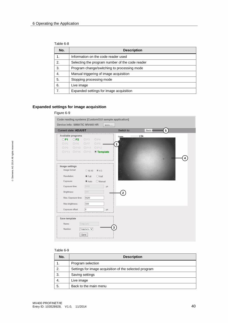
Table 6-8
No. Description
1. Information on the code reader used2. Selecting the program number of the code reader3. Program change/switching to processing mode4. Manual triggering of image acquisition5. Stopping processing mode6. Live image7. Expanded settings for image acquisition
Expanded settings for image acquisitionFigure 6-9
Table 6-9
No. Description
1. Program selection2. Settings for image acquisition of the selected program3. Saving settings4. Live image5. Back to the main menu
1
2
3
4
5
6 Operating the Application
MV400 PROFINET/IEEntry ID: 103528928, V1.0, 11/2014 41
ãS
iem
ens
AG
2014
All
right
sre
serv
ed
Note The processing mode of the code reader is stopped, when you go to the settingsof the image acquisition.
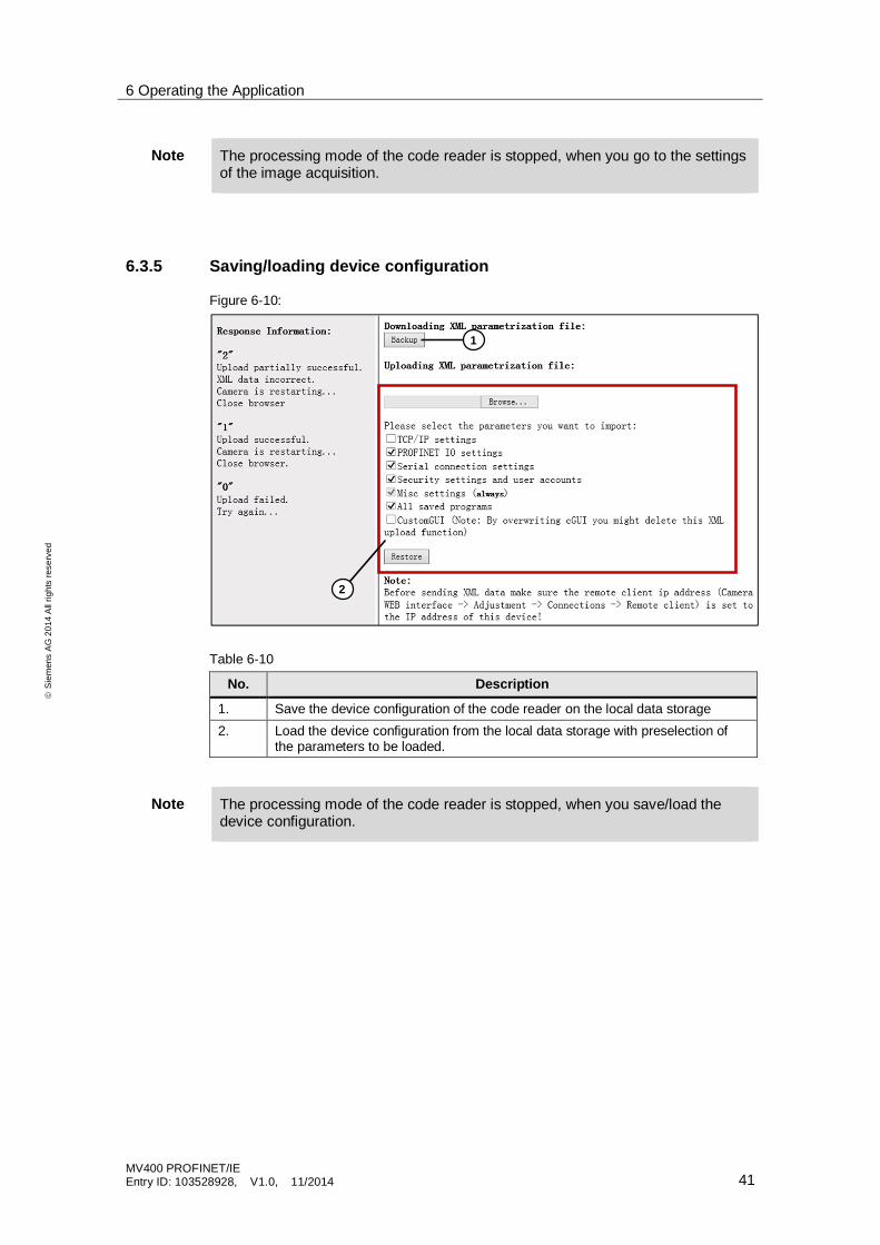
6.3.5 Saving/loading device configuration
Figure 6-10:
Table 6-10
No. Description
1. Save the device configuration of the code reader on the local data storage2. Load the device configuration from the local data storage with preselection of
the parameters to be loaded.
Note The processing mode of the code reader is stopped, when you save/load thedevice configuration.
1
2
7 Further Tips and Tricks
MV400 PROFINET/IEEntry ID: 103528928, V1.0, 11/2014 42
ãS
iem
ens
AG
2014
All
right
sre
serv
ed
7 Further Tips and Tricks
Manual entry by SIMATIC MV300 manual readerAlternatively to the manual entry function of this application, you can also use thefollowing manual readers, in order to read the codesTable 7-1
Component Article number
SIMATIC MV320 6GF3320-0HT01SIMATIC MV325 6GF3325-0HT01SIMATIC MV340 6GF3340-0HT01
For this purpose, connect the code reader via USB directly to your HMI and selectthe field of the read result (chap. 6.3), in order to send the codes directly via themanual readers to the controller.
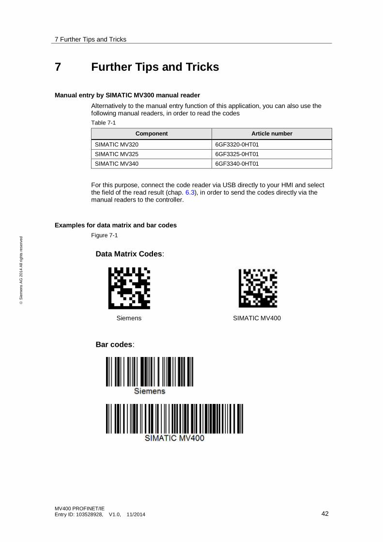
Examples for data matrix and bar codesFigure 7-1
Siemens SIMATIC MV400
Data Matrix Codes:
Bar codes:
8 References
MV400 PROFINET/IEEntry ID: 103528928, V1.0, 11/2014 43
ãS
iem
ens
AG
2014
All
right
sre
serv
ed
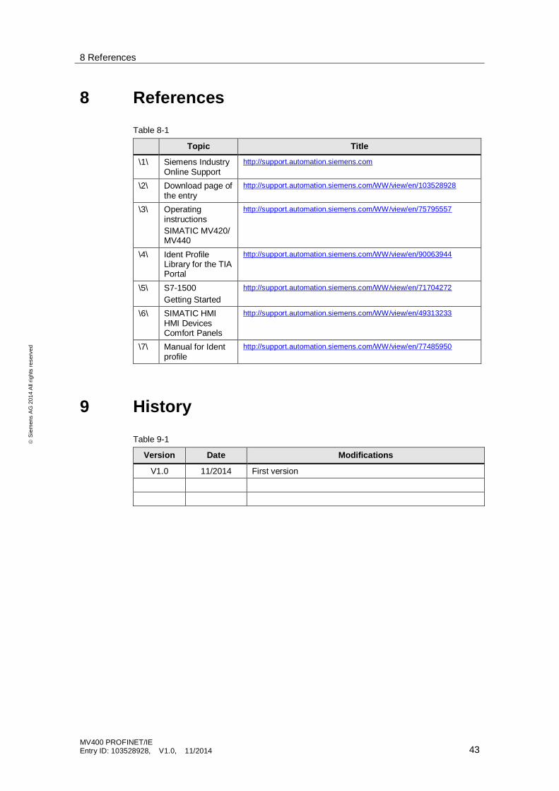
8 References
Table 8-1
Topic Title
\1\ Siemens IndustryOnline Support
http://support.automation.siemens.com
\2\ Download page ofthe entry
http://support.automation.siemens.com/WW/view/en/103528928
\3\ OperatinginstructionsSIMATIC MV420/MV440
http://support.automation.siemens.com/WW/view/en/75795557
\4\ Ident ProfileLibrary for the TIAPortal
http://support.automation.siemens.com/WW/view/en/90063944
\5\ S7-1500Getting Started
http://support.automation.siemens.com/WW/view/en/71704272
\6\ SIMATIC HMIHMI DevicesComfort Panels
http://support.automation.siemens.com/WW/view/en/49313233
\7\ Manual for Identprofile
http://support.automation.siemens.com/WW/view/en/77485950
9 History
Table 9-1
Version Date Modifications
V1.0 11/2014 First version