Embed Size (px)
Citation preview

https://support.industry.siemens.com/cs/ww/en/view/109476801
Application Description 08/2015
Controlling a Fan (ebm-papst) via Modbus RTU SIMATIC S7-1200

Warranty and Liability
Controlling a fan (ebm-papst) via Modbus RTU Entry-ID: 109476801, 1.0, 08/2015 2
S
iem
en
s A
G 2
01
5 A
ll ri
gh
ts r
ese
rve
d
Warranty and Liability
Note The Application Examples are not binding and do not claim to be complete regarding the circuits shown, equipping and any eventuality. The Application Examples do not represent customer-specific solutions. They are only intended to provide support for typical applications. You are responsible for ensuring that the described products are used correctly. These application examples do not relieve you of the responsibility to use safe practices in application, installation, operation and maintenance. When using these Application Examples, you recognize that we cannot be made liable for any damage/claims beyond the liability clause described. We reserve the right to make changes to these Application Examples at any time without prior notice. If there are any deviations between the recommendations provided in these application examples and other Siemens publications – e.g. Catalogs – the contents of the other documents have priority.
We do not accept any liability for the information contained in this document.
Any claims against us – based on whatever legal reason – resulting from the use of the examples, information, programs, engineering and performance data etc., described in this Application Example shall be excluded. Such an exclusion shall not apply in the case of mandatory liability, e.g. under the German Product Liability Act (“Produkthaftungsgesetz”), in case of intent, gross negligence, or injury of life, body or health, guarantee for the quality of a product, fraudulent concealment of a deficiency or breach of a condition which goes to the root of the contract (“wesentliche Vertragspflichten”). The damages for a breach of a substantial contractual obligation are, however, limited to the foreseeable damage, typical for the type of contract, except in the event of intent or gross negligence or injury to life, body or health. The above provisions do not imply a change of the burden of proof to your detriment.
Any form of duplication or distribution of these Application Examples or excerpts hereof is prohibited without the expressed consent of the Siemens AG.
Security informa-tion
Siemens provides products and solutions with industrial security functions that support the secure operation of plants, solutions, machines, equipment and/or networks. They are important components in a holistic industrial security concept. With this in mind, Siemens’ products and solutions undergo continuous development. Siemens recommends strongly that you regularly check for product updates.
For the secure operation of Siemens products and solutions, it is necessary to take suitable preventive action (e.g. cell protection concept) and integrate each component into a holistic, state-of-the-art industrial security concept. Third-party products that may be in use should also be considered. For more information about industrial security, visit http://www.siemens.com/industrialsecurity.
To stay informed about product updates as they occur, sign up for a product-specific newsletter. For more information, visit https://support.industry.siemens.com.

Table of Contents
Controlling a fan (ebm-papst) via Modbus RTU Entry-ID: 109476801, 1.0, 08/2015 3
S
iem
en
s A
G 2
01
5 A
ll ri
gh
ts r
ese
rve
d
Table of Contents Warranty and Liability ................................................................................................. 2
1 Task ..................................................................................................................... 5
1.1 Overview............................................................................................... 5
2 Solution............................................................................................................... 6
2.1 Solution overview ................................................................................. 6 2.2 Description of the core functions .......................................................... 7 2.3 Hardware and software components ................................................... 9 2.3.1 Validity .................................................................................................. 9 2.3.2 Used components ................................................................................ 9
3 Function Mechanisms ..................................................................................... 11
3.1 General overview ............................................................................... 11 3.2 Register .............................................................................................. 12 3.2.1 Holding register .................................................................................. 12 3.2.2 Input register ...................................................................................... 13 3.3 PLC data types ................................................................................... 14 3.3.1 “typeProductionData” ......................................................................... 14 3.3.2 “typeRead” .......................................................................................... 14 3.3.3 “typeData” ........................................................................................... 14 3.3.4 “typeWrite” .......................................................................................... 15 3.3.5 “typeCyclic” ......................................................................................... 15 3.3.6 “typeManual” ...................................................................................... 15 3.3.7 “typeHMI” ............................................................................................ 16 3.4 FB “EbmPapst” ................................................................................... 17 3.5 FC “ReadWrite” .................................................................................. 21 3.5.1 Function mechanisms ........................................................................ 23 3.5.2 Sequential call of FC “ReadWrite” ...................................................... 25
4 Installation and Startup ................................................................................... 27
4.1 Installation of the hardware ................................................................ 27 4.2 Network connections .......................................................................... 28 4.2.1 Setting the PG/PC interface ............................................................... 29 4.3 Configuration instructions ................................................................... 29 4.3.1 Adjusting the device configuration ..................................................... 29 4.3.2 Downloading the controller project part .............................................. 30 4.4 HMI project part .................................................................................. 31 4.4.1 Configuring the HMI ........................................................................... 31
Downloading the HMI project part into the KTP900 Basic ................. 32 Starting the PC runtime ...................................................................... 33
5 Operation of the Application .......................................................................... 34
5.1 Overview (start screen) ...................................................................... 34 5.2 Recurrent display elements ................................................................ 36 5.2.1 Cyclically retrieved values (input registers) ........................................ 36 5.2.2 Writing to the holding registers ........................................................... 36
Default settings to operate the application ......................................... 37 5.2.3 Status evaluation ................................................................................ 38 5.3 Trend view .......................................................................................... 39 5.4 All parameters .................................................................................... 40 5.5 Alarm buffer ........................................................................................ 41 5.6 System diagnostics ............................................................................ 42 5.7 Settings............................................................................................... 43 5.7.1 System time/PLC ................................................................................ 43
System time ........................................................................................ 43

Table of Contents
Controlling a fan (ebm-papst) via Modbus RTU Entry-ID: 109476801, 1.0, 08/2015 4
S
iem
en
s A
G 2
01
5 A
ll ri
gh
ts r
ese
rve
d
PLC ............................................................................................ 44 FB “EbmPapst” ................................................................................... 44
5.7.2 Brightness .......................................................................................... 44 5.7.3 User display ........................................................................................ 45 5.7.4 System................................................................................................ 45
6 Related Literature ............................................................................................ 46
7 Contact.............................................................................................................. 47
8 History............................................................................................................... 47

1 Task
1.1 Overview
Controlling a fan (ebm-papst) via Modbus RTU Entry-ID: 109476801, 1.0, 08/2015 5
S
iem
en
s A
G 2
01
5 A
ll ri
gh
ts r
ese
rve
d
1 Task
1.1 Overview
Introduction
ebm-papst offers fans with an integrated RS485 interface that can be controlled via the Modbus RTU protocol.
These fans are to be connected to a SIMATIC PLC, monitored and controlled.
Overview of the automation task
The figure below provides an overview of the automation task.
Figure 1-1
ebm-papst
Modbus fan
SIMATIC PLC
SIMATIC
Basic Panel
Modbus RTU
Description of the automation task
The application has to satisfy the following requirements:
Communication between the SIMATIC PLC and the ebm-papst fan (reading and writing the parameters) via Modbus RTU.
Operation and monitoring of the motor parameters via HMI

2 Solution
2.1 Solution overview
Controlling a fan (ebm-papst) via Modbus RTU Entry-ID: 109476801, 1.0, 08/2015 6
S
iem
en
s A
G 2
01
5 A
ll ri
gh
ts r
ese
rve
d
2 Solution
2.1 Solution overview
Display
The following figure shows the most important components of the solution:
Figure 2-1
ebm-papst
Modbus fan
SIMATIC
S7-1200SIMATIC HMI
KTP900 BASIC
PROFINET IE
MODBUS RTU
CB 1241
RS485
Setup
A SIMATIC S7-1200 CPU with firmware V4.1.1 is used as the controller. It exchanges the motor data with the ebm-papst fan using the serial communication board CB 1241 RS485 via the Modbus RTU data protocol.
To operate and monitor the motor data, a SIMATIC HMI KTP900 BASIC (or its simulation in the TIA Portal) is used.
Configuration was performed with STEP 7 V13 SP1.
NOTE Instead of the CB 1241 RS485 the CM 1241 RS422/485 with 9-pin D-sub connector (6ES7241-1CH32-0XB0) may be used alternatively (\3\).
However, the CB 1241 RS485 is better suited for direct wiring of the fan (without D-sub connector).
2 Solution
2.2 Description of the core functions
Controlling a fan (ebm-papst) via Modbus RTU Entry-ID: 109476801, 1.0, 08/2015 7
S
iem
en
s A
G 2
01
5 A
ll ri
gh
ts r
ese
rve
d
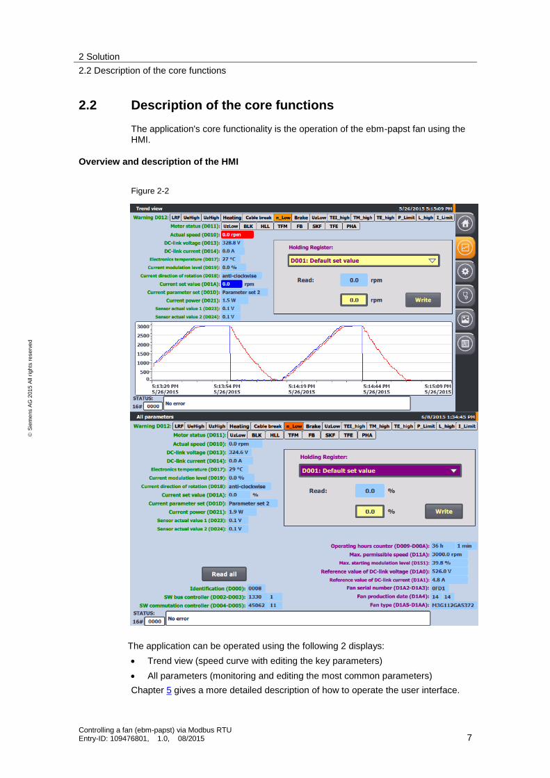
2.2 Description of the core functions
The application's core functionality is the operation of the ebm-papst fan using the HMI.
Overview and description of the HMI
Figure 2-2
The application can be operated using the following 2 displays:
Trend view (speed curve with editing the key parameters)
All parameters (monitoring and editing the most common parameters)
Chapter 5 gives a more detailed description of how to operate the user interface.

2 Solution
2.2 Description of the core functions
Controlling a fan (ebm-papst) via Modbus RTU Entry-ID: 109476801, 1.0, 08/2015 8
S
iem
en
s A
G 2
01
5 A
ll ri
gh
ts r
ese
rve
d
Advantages
In addition to the cyclic reading of the most important input registers of the ebm-papst fan, the application allows you to edit the most common holding registers and to read fan-specific (non-writable) parameters upon request.
This application offers you the following advantages:
Input and output of the parameters with the correct unit and meaning through the KTP900 Basic PN operator panel
Cyclic reading of the key input registers
Curve progress of actual and set speed values
Automatic reading of the most common holding registers after selection and subsequent editing
Collective reading of device-specific input registers and non-writable holding registers upon request
Access to all registers via the control program
Delimitation
This application establishes the direct communication between the S7-1200 and a ebm-papst Modbus fan by means of Modbus RTU.
The selected registers are converted to the correct unit according to their meaning in line with the MODBUS parameter specification for “ebm-papst series 84 / 112 / 150 / 200” V5.00 and output.
To safely operate your ebm-papst fan, you have to familiarize yourself with this specification.
This specification does not provide a detailed description of the parameters.
Using this application you can also access other registers from the control program (in addition to the ones selected in chapter 3.2). However, the conversion into the
correct unit is not implemented for these registers.
NOTE The MODBUS parameter specification for “ebm-papst series 84 / 112 / 150 / 200” V5.00 is provided by ebm-papst when purchasing a fan/motor of this series and upon request (see chapter 7).
Required knowledge
Basic knowledge and experience with the following subjects are required for this application:
SIMATIC S7-1200 controller family
TIA Portal engineering interface
MODBUS-RTU communication protocol

2 Solution
2.3 Hardware and software components
Controlling a fan (ebm-papst) via Modbus RTU Entry-ID: 109476801, 1.0, 08/2015 9
S
iem
en
s A
G 2
01
5 A
ll ri
gh
ts r
ese
rve
d
2.3 Hardware and software components
2.3.1 Validity
This application example is valid for
STEP 7 from V13 SP1 (TIA Portal)
SIMATIC S7-1200 for firmware V4.1.1 and higher
2.3.2 Used components
The application was generated with the following components:
Hardware components
Table 2-1
Component Qty Article number Note
POWER SUPPLY S7-1200 PM1207
1 6EP1332-1SH71
COMPACT SWITCH MODULE CSM 1277
1 6GK7277-1AA10-0AA0
CPU 1214C, DC/DC/RELAY, 6DI/4DO/2AI
1 6ES7214-1HG40-0XB0 Firmware V4.1.1 (\6\)
COMMUNICATION BOARD CB 1241, RS485
1 6ES7241-1CH30-1XB0 Alternatively, you can use the COMMUNICATION MODULE CM 1241, RS422/485 with 9-PIN D-SUB CONNECTOR (6ES7241-1CH32-0XB0) (\3\)
SIMATIC HMI KTP900 BASIC
1 6AV2123-2JB03-0AX0 Optional (can also be simulated in WinCC Basic V13 SP1)
Ethernet cable
TP CORD RJ45/RJ45 2M
3 6XV1870-3QH20
Standard rail 1 6ES5 710-8MA11 35 mm
Ebm-papst Modbus fan 1 Type: VarioDrive C M3G112-GA53-72
Manufacturer: ebm-papst (\10\ and \11\)
Standard software components
Table 2-2
Component Qty Article number Note
SIMATIC STEP 7 BASIC V13 SP1
1 6ES7822-0AA03-0YA5 Includes WinCC Basic V13 SP1;
With update 2 (\5\)
SIMATIC STEP 7 BASIC UPGRADE V13 SP1
1 6ES7822-0AA03-0YE5 (optional) only to upgrade STEP 7 Basic V11 or V12

2 Solution
2.3 Hardware and software components
Controlling a fan (ebm-papst) via Modbus RTU Entry-ID: 109476801, 1.0, 08/2015 10
S
iem
en
s A
G 2
01
5 A
ll ri
gh
ts r
ese
rve
d
Sample files and projects
The following list includes all files and projects that are used in this example.
Table 2-3
Component Note
109476801_S7-1200_ebmpapst_CODE_v1d0.zip This zip file contains the STEP 7 project.
109476801_S7-1200_ebmpapst_DOKU_v1d0_en.pdf This document.

3 Function Mechanisms
3.1 General overview
Controlling a fan (ebm-papst) via Modbus RTU Entry-ID: 109476801, 1.0, 08/2015 11
S
iem
en
s A
G 2
01
5 A
ll ri
gh
ts r
ese
rve
d
3 Function Mechanisms
3.1 General overview
Figure 3-1 shows the time sequence of the block calls in the control part of the application project.
Figure 3-1
User program System blocks Data blocks
EbmPapst
Register
MAIN
[OB 1]
Receive_Config[FB612]
SERIALIZE
[FC890]
Tags
Send_Config
[FB611]
Receive_P2P
[FB614]
Receive_Reset
[FB617]
Send_P2P
[FB613]
Modbus_C
omm_Load
[FB640]
Modbus_Master[FB641]
ReadWrite
The core functionality includes the function block “EbmPapst”. This block is called in the cyclic organization block “Main”. The interfaces of FB “EbmPapst” are fed from the data blocks
“Register” (this DB contains the register structure and the order of the data to be read) and
“Tags” (this DB contains the variables to parameterize and operator the FB “EbmPapst”).
The following system blocks are called in the FB “EbmPapst”:
“Modbus_Comm_Load” [FB640] to initialize the Modbus RTU communication

3 Function Mechanisms
3.2 Register
Controlling a fan (ebm-papst) via Modbus RTU Entry-ID: 109476801, 1.0, 08/2015 12
S
iem
en
s A
G 2
01
5 A
ll ri
gh
ts r
ese
rve
d
“Modbus_Master” [FB641] for data exchange of the S7-1200 as the master with the ebm-papst fan as the slave
“SERIALIZE” [FB890] to convert words into an array of bytes and subsequent output as a string
The actual values of the function blocks are stored as a multi-instance in the instance data block of the FB “EbmPapst”.
The FC “ReadWrite” serves to access additional registers which are not listed in the following chapter. It is called in the cyclic organization block “Main”. It has an interface to the FB “EbmPapst” and is fed by the data blocks “Register” and “Tags”.
3.2 Register
3.2.1 Holding register
This application allows you to access the following holding registers through the HMI:
Table 3-1
Address Length Designation Write Reset required
Password required
hex. dec.
D000 53248 1 Reset X - -
D001 53249 1 Default set value X - -
D002 53250 3 Password X - -
D005 53253 1 Control default setting X - X
D009 53257 1 Operating hours counter - - -
D00A 53258 1 Operating minutes counter - - -
D100 53504 1 Fan address X X -
D101 53505 1 Set value source X X -
D102 53506 1 Preferred running direction X - -
D103 53507 1 Save set value X X -
D104 53508 1 Source parameter set X X -
D105 53509 1 Internal parameter set X - -
D106 53510 1 Control mode (parameter set 1) X X -
D107 53511 1 Control mode (parameter set 2) X X -
D112 53522 1 Motor stop enable (parameter set 1) X X -
D113 53523 1 Motor stop enable (parameter set 2) X X -
D114 53524 1 Set value (parameter set 1) - - -
D115 53525 1 Set value (parameter set 2) - - -
D119 53529 1 Maximum speed X X X
D11A 53530 1 Max. permissible speed - - -
D11F 53535 1 Ramp-up time X X -
D120 53536 1 Ramp-down time X X -
D145 53573 1 Ceiling speed for speed monitoring X X X
D148 53576 1 Source direction of rotation X X -
D149 53577 1 Transfer rate X X X
D14A 53578 1 Parity configuration X X X
3 Function Mechanisms
3.2 Register
Controlling a fan (ebm-papst) via Modbus RTU Entry-ID: 109476801, 1.0, 08/2015 13
S
iem
en
s A
G 2
01
5 A
ll ri
gh
ts r
ese
rve
d
Address Length Designation Write Reset required
Password required
hex. dec.
D150 53584 1 Shedding function X X X
D151 53585 1 Max. starting modulation level - - -
D152 53586 1 Number of start attempts X X X
D153 53587 1 Relay drop-out delay X X -
D15B 53595 1 Emergency operation running direction
X X X
D15C 53596 1 Emergency operation function on/off X X X
D15D 53597 1 Set value for emergency operation X X X
D15E 53598 1 Emergency operation time lag X X X
D1A0 53664 1 Reference value of DC-link voltage - - -
D1A1 53665 1 Reference value of DC-link current - - -
D1A2 53666 2 Fan serial number - - -
D1A4 53668 1 Fan production date - - -
D1A5 53669 6 Fan type - - -
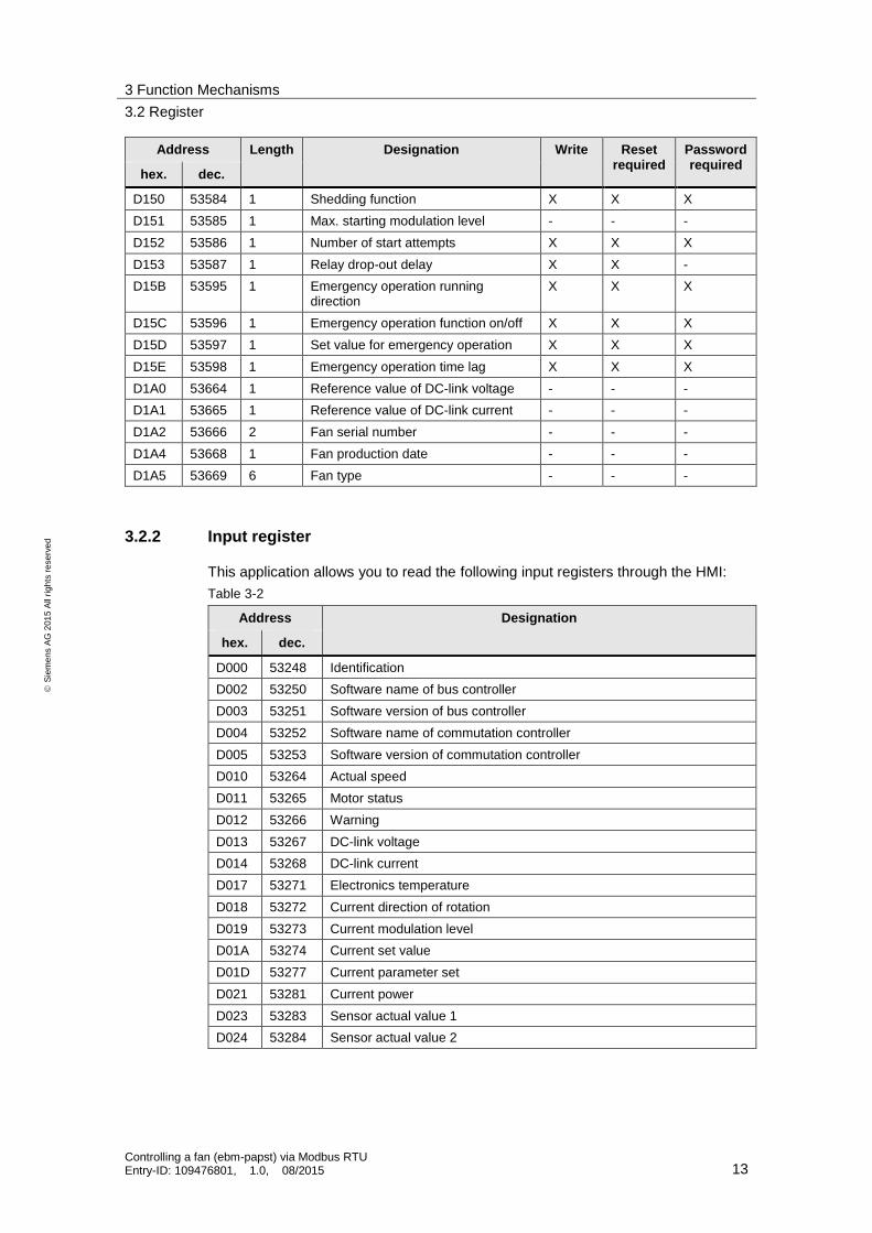
3.2.2 Input register
This application allows you to read the following input registers through the HMI:
Table 3-2
Address Designation
hex. dec.
D000 53248 Identification
D002 53250 Software name of bus controller
D003 53251 Software version of bus controller
D004 53252 Software name of commutation controller
D005 53253 Software version of commutation controller
D010 53264 Actual speed
D011 53265 Motor status
D012 53266 Warning
D013 53267 DC-link voltage
D014 53268 DC-link current
D017 53271 Electronics temperature
D018 53272 Current direction of rotation
D019 53273 Current modulation level
D01A 53274 Current set value
D01D 53277 Current parameter set
D021 53281 Current power
D023 53283 Sensor actual value 1
D024 53284 Sensor actual value 2

3 Function Mechanisms
3.3 PLC data types
Controlling a fan (ebm-papst) via Modbus RTU Entry-ID: 109476801, 1.0, 08/2015 14
S
iem
en
s A
G 2
01
5 A
ll ri
gh
ts r
ese
rve
d
3.3 PLC data types
3.3.1 “typeProductionData”
The PLC data type “typeProductionData” includes the fan's manufacturing data.
Table 3-3
Name Data type Description
serialNumber String[4] Fan serial number (consecutive number)
productionDate “typeProductionDate” PLC data type with the fan's production date (year/week)
fanType String[12] Fan type (designation)
3.3.2 “typeRead”
The PLC data type “typeRead” includes the placeholder to read registers.
Table 3-4
Name Data type Description
req Bool Request to read a register
data “typeData” PLC data type with the read parameters
uint Uint Read data value
3.3.3 “typeData”
The PLC data type “typeData” includes the parameters for reading and writing to the registers.
Table 3-5
Name Data type Description
mode USInt Mode selection: Defines the type of request [read (0 for holding registers; 104 for input registers) or write(1)]
addr UDInt Start address in the slave: Defines the start address of the data to access:
453249 through 453675 (16#D000 through 16#D1AA) for reading (mode = 0) and writing holding registers (mode = 1)
53248 through 53286 (16#D000 through 16#D026) for reading input registers (mode = 104)
len Uint Data length: Defines the number of words which this request should access (max. 9 words possible due to slave).

3 Function Mechanisms
3.3 PLC data types
Controlling a fan (ebm-papst) via Modbus RTU Entry-ID: 109476801, 1.0, 08/2015 15
S
iem
en
s A
G 2
01
5 A
ll ri
gh
ts r
ese
rve
d
3.3.4 “typeWrite”
The PLC data type “typeWrite” includes the placeholder to read registers.
Table 3-6
Name Data type Description
req Bool Request to write to registers
data “typeData” PLC data type with the write parameters
uint Array[0..2] of Uint
Data values to write in the “Uint” data format
minUint Uint Lower input limit value for the HMI input field for the “Uint” data format
maxUint Uint Upper input limit value for the HMI input field for the “Uint” data format
real Real Data value to write in the “Real” data format
maxReal Real Upper input limit value for the HMI input field for the “Real” data format
3.3.5 “typeCyclic”
The PLC data type “typeCyclic” includes the order of the data to be exchanged.
Table 3-7
Name Data type Description
last Int Last field element to be edited
data Array[0..9] of “typeData”
Order of the data to exchange
3.3.6 “typeManual”
The PLC data type “typeManual” contains the information for exchanging data between the FB “EbmPapst” and the FC “ReadWrite”.
Table 3-8
Name Data type Description
step USInt Step counter for FC “ReadWrite”
req Bool Request of manual access via FC “ReadWrite”
data “typeData” Contains the information which data to read
dataPtr Array[0..8] of UInt Data buffer with the values to read or write
busy Bool FC “ReadWrite” is being edited
done Bool FC “ReadWrite” was completed without errors (active for one cycle)
error Bool FC “ReadWrite” was completed with errors (active for one cycle)
errorStatus Word Status evaluation (error code) of FC “ReadWrite”

3 Function Mechanisms
3.3 PLC data types
Controlling a fan (ebm-papst) via Modbus RTU Entry-ID: 109476801, 1.0, 08/2015 16
S
iem
en
s A
G 2
01
5 A
ll ri
gh
ts r
ese
rve
d
3.3.7 “typeHMI”
The PLC data type “typeHMI” contains information about the visibility display in the HMI.
Table 3-9
Name Data type Description
unit “typeUnit” Includes information about the correct representation of the setpoint unit (“1/min” or “%”)
writeInvisible Bool Hides the write request
readAllBusy Bool Is TRUE for as long as the “Read all registers” job is executed
3 Function Mechanisms
3.4 FB “EbmPapst”
Controlling a fan (ebm-papst) via Modbus RTU Entry-ID: 109476801, 1.0, 08/2015 17
S
iem
en
s A
G 2
01
5 A
ll ri
gh
ts r
ese
rve
d
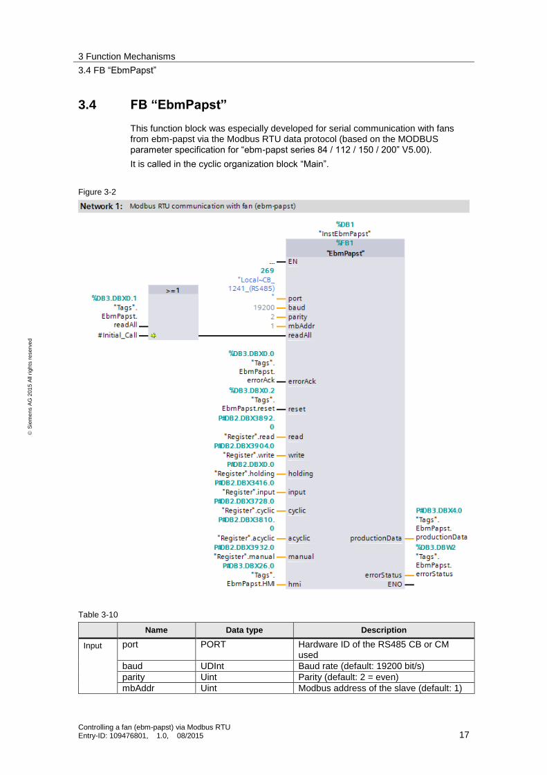
3.4 FB “EbmPapst”
This function block was especially developed for serial communication with fans from ebm-papst via the Modbus RTU data protocol (based on the MODBUS parameter specification for “ebm-papst series 84 / 112 / 150 / 200” V5.00).
It is called in the cyclic organization block “Main”.
Figure 3-2
Table 3-10
Name Data type Description
Input port PORT Hardware ID of the RS485 CB or CM used
baud UDInt Baud rate (default: 19200 bit/s)
parity Uint Parity (default: 2 = even)
mbAddr Uint Modbus address of the slave (default: 1)

3 Function Mechanisms
3.4 FB “EbmPapst”
Controlling a fan (ebm-papst) via Modbus RTU Entry-ID: 109476801, 1.0, 08/2015 18
S
iem
en
s A
G 2
01
5 A
ll ri
gh
ts r
ese
rve
d
Name Data type Description
readAll Bool Request to read all predefined registers (in the project OR operation from HMI variable “Tags.EbmPapst.readAll “and initial pass of OB1 “Inital_Call”)
errorAck Bool Acknowledgment of the pending error message (“status”)
reset Bool Reset, restart block
Output productionData “typeProductionData” Fan production data
errorStatus Word Status evaluation (error code)
InOut read “typeRead” PLC data type to read a register
write “typeWrite” PLC data type to write holding registers
holding Array[53248..53674] of “typeRegister”
Memory buffer of holding registers (16#D000 through 16#D1AA)
input Array[53248..53286] of “typeRegister”
Memory buffer of input registers (16#D000 through 16#D026)
cyclic “typeCyclic” PLC data type with the order of the data to be exchanged cyclically
acyclic “typeCyclic” PLC data type with the order of the data to be exchanged acyclically
manual “typeManual” PLC data type to exchange data with the FC “ReadWrite”
hmi “typeHMI” PLC data type with display information for the HMI
The FB “EbmPapst” includes the calls of the system blocks “Modbus_Comm_Load” and “Modbus_Master”.
The “Modbus_Master” only allows blocks to be handed to the parameter “DATA_PTR” in which the attribute property “optimized block access” is not enabled. No block of this application (FB or DB) has the property “optimized block access”. This prevents cycle time increases due to recopying optimized DBs in non-optimized DBs.
NOTE For a more detailed description of the communication instructions “Modbus_Comm_Load” and “Modbus_Master”, see the STEP 7 V13 SP1 online help or the chapter “Modbus RTU” in the S7-1200 system manual (\8\).

3 Function Mechanisms
3.4 FB “EbmPapst”
Controlling a fan (ebm-papst) via Modbus RTU Entry-ID: 109476801, 1.0, 08/2015 19
S
iem
en
s A
G 2
01
5 A
ll ri
gh
ts r
ese
rve
d
The FB “EbmPapst” reads the most important input registers of the ebm-papst fans in cyclic intervals of approximately 500 ms. Additionally, you can retrieve and write to predefined holding registers in connection with the configured HMI (see chapter 3.2).
The FC “ReadWrite” enables you to access further registers in the control program part (see chapter 3.5).
Program workflow
Figure 3-3 shows the schematic structure of the FB “EbmPapst”.
Figure 3-3
read
write
readAll
Index
Acyclic
Index
Cyclic
Index
Indexwrite
mode = 0
mode = 104
write read
Register
Index
The sequence for reading the input registers is processed cyclically as a function of the running index “IndexCyclic”. The information (access mode “mode”, register address “addr” and register length “len”) are provided as start values in the interface parameter “cyclic” in the field 0 to 7.
The following is written into the last field (“cyclic.last”) via the HMI depending on the request (“read”, “readAll” or “write”):
the holding register to read (provided in the interface parameter “read”)
the sequence for reading the acyclic registers as a function of the running index “IndexAcyclic” (provided in the interface parameter “acyclic”)
the holding register to write to (provided in the interface parameter “write”)
The field (“cyclic.last”) is only processed if the data length “len” is greater than zero.

3 Function Mechanisms
3.4 FB “EbmPapst”
Controlling a fan (ebm-papst) via Modbus RTU Entry-ID: 109476801, 1.0, 08/2015 20
S
iem
en
s A
G 2
01
5 A
ll ri
gh
ts r
ese
rve
d
Based on the running index “IndexCyclic”, the information is transferred to the static placeholder “statDataAct” and handed to the communication block “Modbus_Master”.
The system block “Modbus_Master” provides the interface for exchanging data with the ebm-papst fan via Modbus RTU. The 9-word field “dataPtr” in the static parameter “statModbusMaster” functions as a data buffer for the read values/the values to write. It is limited to 9 words due to the permitted maximum telegram length of the fan.
With read access, the read data are successively (“RegisterIndex”) written into the corresponding register file (“Index”) depending on the access mode:
Interface parameter “holding” for the holding registers (“mode” = 0)
Interface parameter “input” for the input registers (“mode” = 104)
If necessary, the read value (“uint”) is subsequently converted into the corresponding floating point value (“real”) depending on the calculation instruction (“calc”).
With write access (“write.req”), the entered floating point value (“real”) is converted into the corresponding data value in the format “Uint” if necessary and subsequently transmitted into the data buffer “dataPtr” of the Modbus_Master and executed for the holding register to write based on the calculation instruction (“calc”).
As the only exception, the holding register “Password” to write to has a length of 3 words (see Table 3-1). Here, the first and additionally the two following field elements are transmitted (“dataPtr [0..2] = uint [0..2]”).
3 Function Mechanisms
3.5 FC “ReadWrite”
Controlling a fan (ebm-papst) via Modbus RTU Entry-ID: 109476801, 1.0, 08/2015 21
S
iem
en
s A
G 2
01
5 A
ll ri
gh
ts r
ese
rve
d
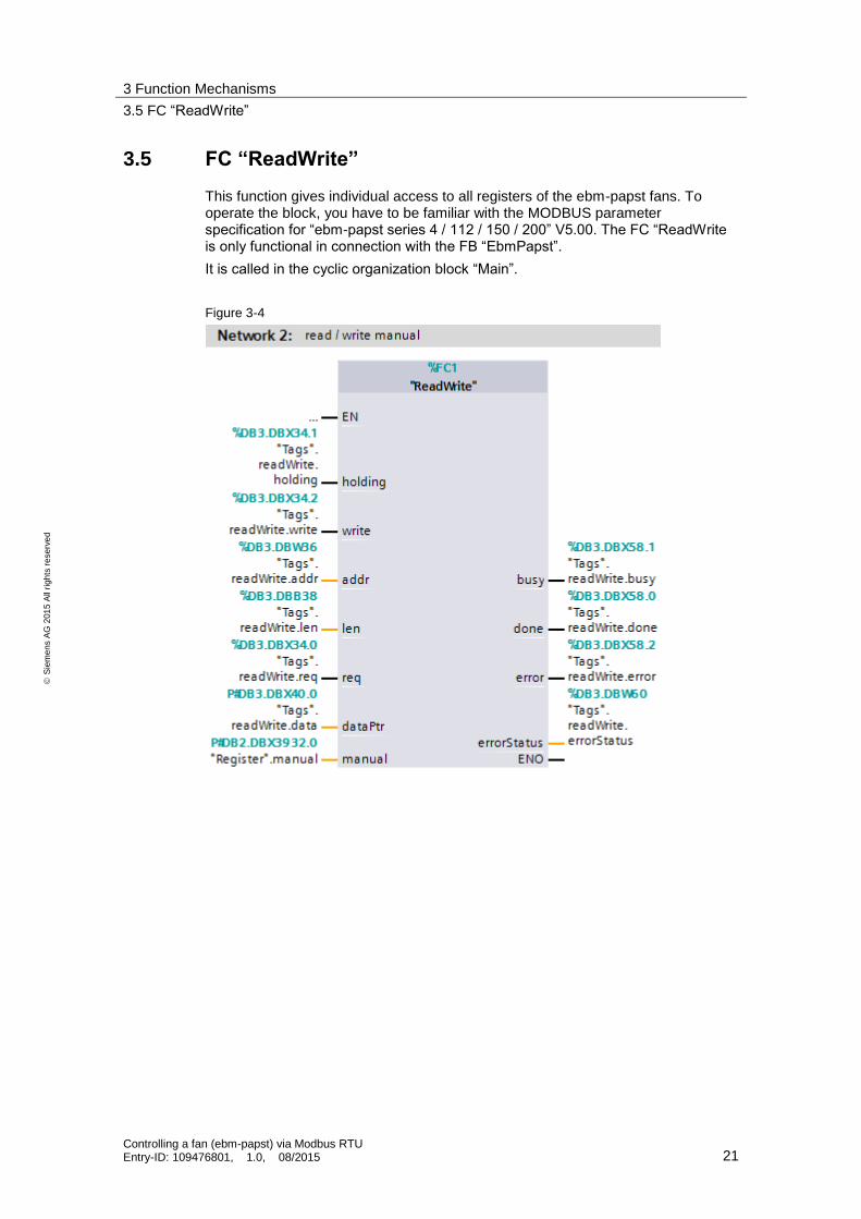
3.5 FC “ReadWrite”
This function gives individual access to all registers of the ebm-papst fans. To operate the block, you have to be familiar with the MODBUS parameter specification for “ebm-papst series 4 / 112 / 150 / 200” V5.00. The FC “ReadWrite is only functional in connection with the FB “EbmPapst”.
It is called in the cyclic organization block “Main”.
Figure 3-4
3 Function Mechanisms
3.5 FC “ReadWrite”
Controlling a fan (ebm-papst) via Modbus RTU Entry-ID: 109476801, 1.0, 08/2015 22
S
iem
en
s A
G 2
01
5 A
ll ri
gh
ts r
ese
rve
d
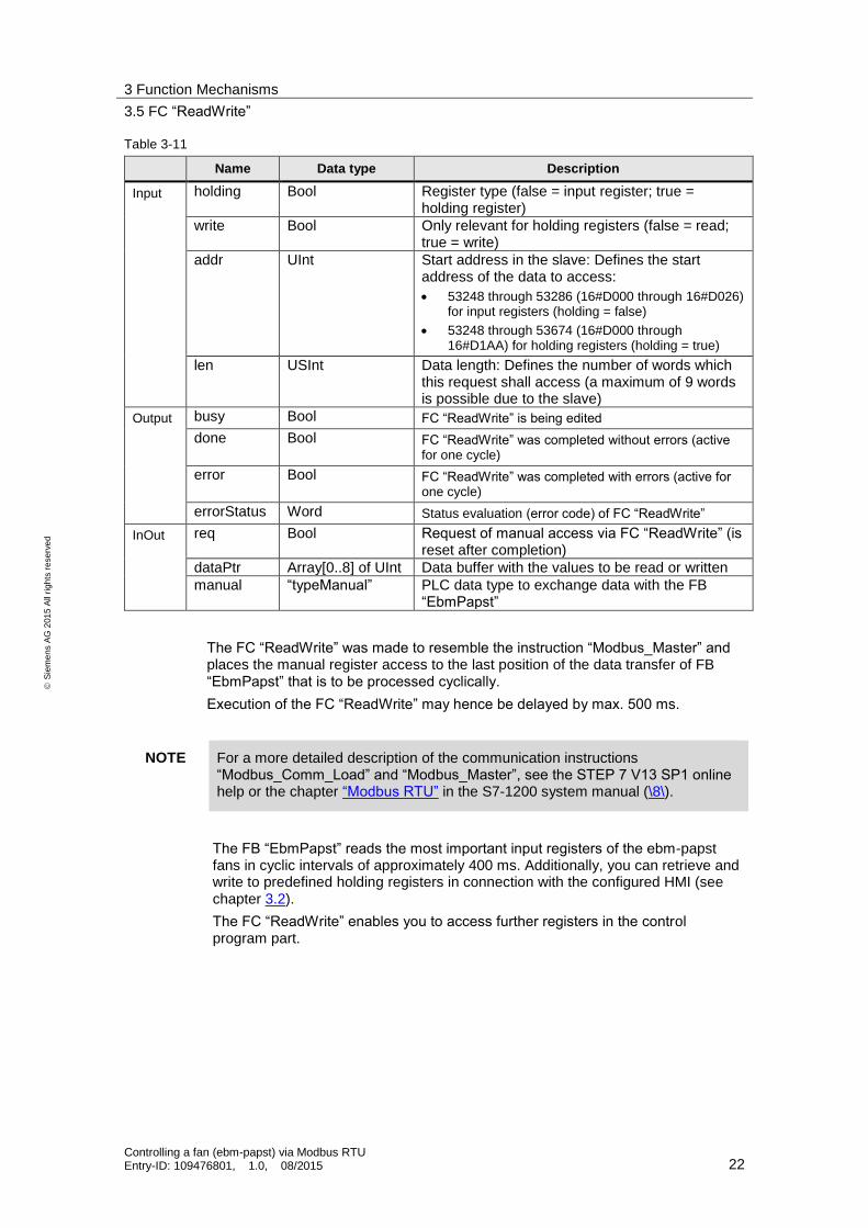
Table 3-11
Name Data type Description
Input holding Bool Register type (false = input register; true = holding register)
write Bool Only relevant for holding registers (false = read; true = write)
addr UInt Start address in the slave: Defines the start address of the data to access:
53248 through 53286 (16#D000 through 16#D026) for input registers (holding = false)
53248 through 53674 (16#D000 through 16#D1AA) for holding registers (holding = true)
len USInt Data length: Defines the number of words which this request shall access (a maximum of 9 words is possible due to the slave)
Output busy Bool FC “ReadWrite” is being edited
done Bool FC “ReadWrite” was completed without errors (active for one cycle)
error Bool FC “ReadWrite” was completed with errors (active for one cycle)
errorStatus Word Status evaluation (error code) of FC “ReadWrite”
InOut req Bool Request of manual access via FC “ReadWrite” (is reset after completion)
dataPtr Array[0..8] of UInt Data buffer with the values to be read or written
manual “typeManual” PLC data type to exchange data with the FB “EbmPapst”
The FC “ReadWrite” was made to resemble the instruction “Modbus_Master” and places the manual register access to the last position of the data transfer of FB “EbmPapst” that is to be processed cyclically.
Execution of the FC “ReadWrite” may hence be delayed by max. 500 ms.
NOTE For a more detailed description of the communication instructions “Modbus_Comm_Load” and “Modbus_Master”, see the STEP 7 V13 SP1 online help or the chapter “Modbus RTU” in the S7-1200 system manual (\8\).
The FB “EbmPapst” reads the most important input registers of the ebm-papst fans in cyclic intervals of approximately 400 ms. Additionally, you can retrieve and write to predefined holding registers in connection with the configured HMI (see chapter 3.2).
The FC “ReadWrite” enables you to access further registers in the control program part.

3 Function Mechanisms
3.5 FC “ReadWrite”
Controlling a fan (ebm-papst) via Modbus RTU Entry-ID: 109476801, 1.0, 08/2015 23
S
iem
en
s A
G 2
01
5 A
ll ri
gh
ts r
ese
rve
d
3.5.1 Function mechanisms
The function mechanism is demonstrated at the example of “reading the 6 holding registers starting from address 16#D108” in Figure 3-5.
Figure 3-5
v
req
done
Index
Cyclic
FB „EbmPapst“
InOut „manual“
FC „ReadWrite“
v
The task is transmitted to the FC “ReadWrite” via the following input parameters:
“holding” = “TRUE” (register type: holding register)
“write” = “FALSE” (access type: read)
“addr” = 53512 (corresponds to 16#D108)
“len” = 6 (6 words are to be read)
The FC “ReadWrite” converts this information for the request “req” into the parameter in the PLC data type “typeData” which the instruction “Modbus_Master” understands:
“mode” = 0 (corresponds to: “read holding register”)
“addr” = 453513 (= holding register offset 400001 + x)
“len” = 6 (6 words are to be read)
This data type is transferred “manually” to the FB “EbmPapst” by means of the input/output data and written into the last field (“cyclic.last”) of the data transfer jobs (“cyclic”) to be processed cyclically.
If the running index “IndexCyclic” equals “cyclic.last”, the information is transmitted to the static placeholder “statDataAct” and handed to the communication block “Modbus_Master”.

3 Function Mechanisms
3.5 FC “ReadWrite”
Controlling a fan (ebm-papst) via Modbus RTU Entry-ID: 109476801, 1.0, 08/2015 24
S
iem
en
s A
G 2
01
5 A
ll ri
gh
ts r
ese
rve
d
The system block “Modbus_Master” receives the read data and writes it into the data buffer “dataPtr” in the input/output data “manual” and transmits it to the FC “ReadWrite” in case of successful transmission “done”.
The output “done” is only active for one cycle and resets the request bit “req”.
Only the data to be transmitted is valid respectively (defined by the data length “len”). Before the FC “ReadWrite” is called again, the data has to be processed or it will be overwritten.
The read registers (“holding” or “input”) are also written to the correct field in the DB “Register”.
Besides the example “Reading holding registers” already described you can also read input registers or write to holding registers.
If errors occur, the output bit “error” is set for one cycle. The status “errorStatus” delivers the corresponding error code (remains pending).
NOTE For a detailed list of the error codes for the “Modbus_Master” instruction, refer to the online help of the TIA Portal using F1.
You can check the function of the FC “ReadWrite” using the watch table “ReadWrite”:
Figure 3-6
3 Function Mechanisms
3.5 FC “ReadWrite”
Controlling a fan (ebm-papst) via Modbus RTU Entry-ID: 109476801, 1.0, 08/2015 25
S
iem
en
s A
G 2
01
5 A
ll ri
gh
ts r
ese
rve
d
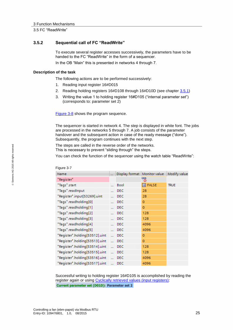
3.5.2 Sequential call of FC “ReadWrite”
To execute several register accesses successively, the parameters have to be handed to the FC “ReadWrite” in the form of a sequencer.
In the OB “Main” this is presented in networks 4 through 7.
Description of the task
The following actions are to be performed successively:
1. Reading input register 16#D015
2. Reading holding registers 16#D108 through 16#D10D (see chapter 3.5.1)
3. Writing the value 1 to holding register 16#D105 (“internal parameter set”) (corresponds to: parameter set 2)
Figure 3-8 shows the program sequence.
The sequencer is started in network 4. The step is displayed in white font. The jobs are processed in the networks 5 through 7. A job consists of the parameter handover and the subsequent action in case of the ready message (“done”). Subsequently, the program continues with the next step.
The steps are called in the reverse order of the networks. This is necessary to prevent “sliding through” the steps.
You can check the function of the sequencer using the watch table “ReadWrite”:
Figure 3-7
Successful writing to holding register 16#D105 is accomplished by reading the register again or using Cyclically retrieved values (input registers):

3 Function Mechanisms
3.5 FC “ReadWrite”
Controlling a fan (ebm-papst) via Modbus RTU Entry-ID: 109476801, 1.0, 08/2015 26
S
iem
en
s A
G 2
01
5 A
ll ri
gh
ts r
ese
rve
d
Figure 3-8
1holding := FALSE
write := FALSEaddr := 16#D015
len := 1Req := TRUE
0Start/Stop
done
start
Processing received data
2holding := TRUEwrite := FALSE
addr := 16#D108len := 6
Req := TRUE
done
Processing received data
3holding := TRUE
write := TRUEaddr := 16#D106
len := 6data[0] := 1
Req := TRUE
done
Start := FALSE
Network 7
Network 6
Network 5
Network 4

4 Installation and Startup
4.1 Installation of the hardware
Controlling a fan (ebm-papst) via Modbus RTU Entry-ID: 109476801, 1.0, 08/2015 27
S
iem
en
s A
G 2
01
5 A
ll ri
gh
ts r
ese
rve
d
4 Installation and Startup The application was set up using a CPU 1214C and a 1241 RS485 communication board. If you are using a different CPU, please follow the instructions in chapter 4.3.1.
Instead of the CB 1241 RS485 communication board you can also use the CM 1241 RS422/485 communication module to communicate with the ebm-papst Modbus fan (here: “VarioDrive C”) (\3\).
4.1 Installation of the hardware
The figure below shows the hardware configuration of the application:
Figure 4-1
L1N
PE+24V
M
L+ M PE
PN
M L+ PN
Ebm-papst
VarioDrive CSIMATIC Panel
KTP900
SIMATIC S7
CPU 1214C
SIMATIC S7
CB 1241 RS485
M TA T/RA T/RB TB
N
(1.2)L1
(1.1)
PE
RSA
(3.1)RSB
(3.2)
GND
(3.3)
L+ M PE
SIMATIC S7
CSM 1277
L1 N PE L+ M
SIMATIC S7
PM 1207
P1 P2 P3
PC / PG
192.168.0.242
192.168.0.2
192.168.0.1
Shielding
Table 4-1
No. Action Remarks
1. Install all required S7-1200 components on a top hat rail.
See Table 2-1
2. Wire and connect all required components as described.
Pay special attention to the crossed communication link between CB 1241 RS485 and fan (T/RA – RSB and T/RB – RSA).
See S7-1200 manual (\8\) Chapter A “Technical Data” and #operating instructions for ebm-papst motor (\11\)

4 Installation and Startup
4.2 Network connections
Controlling a fan (ebm-papst) via Modbus RTU Entry-ID: 109476801, 1.0, 08/2015 28
S
iem
en
s A
G 2
01
5 A
ll ri
gh
ts r
ese
rve
d
No. Action Remarks
3. Finally, connect the fan (here: “VarioDrive C”) and the SIMATIC PM 1207 power supply to the AC power system (230 V).
4.2 Network connections
To configure the controller and the HMI, the LAN network card of the programming unit needs a static IP address. The configuration of the LAN connection is described in the following.
Table 4-2
No. Action Remarks
1. Click “Start > Control Panel > Network and Sharing Center > Change adapter settings” to open the network connections.
Select your network connection.
Right-click to open the properties.
2. Select the option “Internet Protocol Version 4 (TCP/Ipv4)” and open its properties.

4 Installation and Startup
4.3 Configuration instructions
Controlling a fan (ebm-papst) via Modbus RTU Entry-ID: 109476801, 1.0, 08/2015 29
S
iem
en
s A
G 2
01
5 A
ll ri
gh
ts r
ese
rve
d
No. Action Remarks
3. Choose “Use the following IP address”.
Select an IP address in the CPU's subnet mask.
Confirm the settings with “OK” and “Close”.
4.2.1 Setting the PG/PC interface
Table 4-3
No. Action Remarks
1. Open the PG/PC interface settings via “Start > Control Panel” to set the correct access path for STEP 7 V13.
Select “S7ONLINE (STEP 7)” as the application's access point.
Select your network card with “(Parameter assignment of your NDIS CP with TCP/IP protocol (RFC-1006))” as the interface parameterization used.
Confirm the settings with “OK”.
4.3 Configuration instructions
4.3.1 Adjusting the device configuration
Table 4-4
No. Action Remarks
1. Network the S7-1200 controller with your programming unit. Assign the IP addresses specified in Figure 4-1 for this purpose.
Configuring the CPU for communication:
S7-1200 manual (\8\)→ Chapter 6.8

4 Installation and Startup
4.3 Configuration instructions
Controlling a fan (ebm-papst) via Modbus RTU Entry-ID: 109476801, 1.0, 08/2015 30
S
iem
en
s A
G 2
01
5 A
ll ri
gh
ts r
ese
rve
d
No. Action Remarks
2. Use STEP 7 V13 SP1 to open the project file (ap13).
See Table 2-3
3. Open the device configuration of the controller “PLC_1”.
4. If necessary, adjust the CPU configured in the project to the real CPU by selecting the configured CPU and clicking the right mouse button to choose “Change device…” (S7-1200 manual (\8\)→ chapter 6.5).
4.3.2 Downloading the controller project part
Table 4-5
No. Action Remarks
1. Save the project if you have changed CPUs.
Select the program folder of the S7-1200 and transfer the program into the controller by clicking the “Download to device” option.
Select the option “Stop all” in the “Load preview” under “Stop modules”.
Select the option “Start all” in the “Load results” under “Start modules” and complete the loading process.
See S7-1200 manual (\8\)→ chapter 15.2

4 Installation and Startup
4.4 HMI project part
Controlling a fan (ebm-papst) via Modbus RTU Entry-ID: 109476801, 1.0, 08/2015 31
S
iem
en
s A
G 2
01
5 A
ll ri
gh
ts r
ese
rve
d
4.4 HMI project part
4.4.1 Configuring the HMI
When using the KTP900 Basic as operator panel, the project-specific IP address (see Figure 4-1) has to be set.
Table 4-6
No. Action Remarks
1. Connect the KTP900 Basic to the power supply voltage.
Access the settings by clicking the “Settings” button in the “Start Center”.
2. Next open the settings of the network interface by clicking the “Network interface” button.
4 Installation and Startup
4.4 HMI project part
Controlling a fan (ebm-papst) via Modbus RTU Entry-ID: 109476801, 1.0, 08/2015 32
S
iem
en
s A
G 2
01
5 A
ll ri
gh
ts r
ese
rve
d
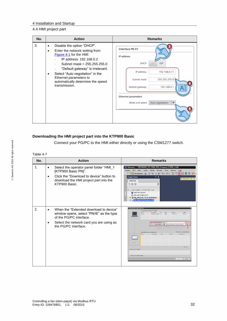
No. Action Remarks
3. Disable the option “DHCP”.
Enter the network setting from Figure 4-1 for the HMI:
– IP address: 192.168.0.2
– Subnet mask = 255.255.255.0
– “Default gateway” is irrelevant.
Select “Auto negotiation” in the Ethernet parameters to automatically determine the speed transmission.
Downloading the HMI project part into the KTP900 Basic
Connect your PG/PC to the HMI either directly or using the CSM1277 switch.
Table 4-7
No. Action Remarks
1. Select the operator panel folder “HMI_1 [KTP900 Basic PN]”.
Click the “Download to device” button to download the HMI project part into the KTP900 Basic.
2. When the “Extended download to device” window opens, select “PN/IE” as the type of the PG/PC interface.
Select the network card you are using as the PG/PC interface.

4 Installation and Startup
4.4 HMI project part
Controlling a fan (ebm-papst) via Modbus RTU Entry-ID: 109476801, 1.0, 08/2015 33
S
iem
en
s A
G 2
01
5 A
ll ri
gh
ts r
ese
rve
d
No. Action Remarks
3. If necessary, activate the option “Overwrite all”.
Click the “Load” button.
4. Depending on the operator panel settings, you may have to trigger the transfer by clicking the “Transfer” button in the Start Center of the KTP900 Basic.
Starting the PC runtime
If you want to use the PG/PC as the operator panel, start the PC runtime as follows:
Table 4-8
No. Action Remarks
1. Select the operator panel folder “PID_HMI [KTP900 Basic PN]”.
Click the “Start simulation” button.

5 Operation of the Application
5.1 Overview (start screen)
Controlling a fan (ebm-papst) via Modbus RTU Entry-ID: 109476801, 1.0, 08/2015 34
S
iem
en
s A
G 2
01
5 A
ll ri
gh
ts r
ese
rve
d
5 Operation of the Application
Overview and description of the HMI
Figure 5-1
Alarm buffer
Trend view
All parameters
Diagnostics
Overview
(Start screen)
System-
functions
The user interface consists of 6 menus:
Overview (start display)
Trend view
All parameters
Alarm buffer
System diagnostics
Settings
5.1 Overview (start screen)
The overview provides information about the current topic. It presents the connection of a fan from ebm-papst to the SIMATIC S7-1200 product family using Modbus-RTU. The integrated system functions “Modbus_Comm_Load” and “Modbus_Master” are available in the SIMATIC S7-1200 controller from CPU firmware V4.1.1 in connection with STEP 7 (TIA Portal) from version V13 SP1 (\3\).
Additionally, operation of the right menu bar is explained. This bar is available on each display.

5 Operation of the Application
5.1 Overview (start screen)
Controlling a fan (ebm-papst) via Modbus RTU Entry-ID: 109476801, 1.0, 08/2015 35
S
iem
en
s A
G 2
01
5 A
ll ri
gh
ts r
ese
rve
d
Figure 5-2
takes you to the “Overview” (the picture above).
takes you to the “Trend view” (Figure 5-6).
takes you to the “All parameters” overview (Figure 5-8).
takes you to the “Alarm buffer” display (Figure 5-10).
takes you to the “System diagnostics” display (Figure 5-11).
takes you to the “Settings” display (Figure 5-12).
The F8 key can be used to switch between German and English.
The currently selected menu is highlighted by the orange background of the icon,
e.g. (for the overview) and in the title in header (left): .
In the right section of the header you can see the current date and time:
The header is also visible in all displays.

5 Operation of the Application
5.2 Recurrent display elements
Controlling a fan (ebm-papst) via Modbus RTU Entry-ID: 109476801, 1.0, 08/2015 36
S
iem
en
s A
G 2
01
5 A
ll ri
gh
ts r
ese
rve
d
5.2 Recurrent display elements
The following subchapters describe the recurrent display elements available both in the “Trend view” display and in the “All parameters” display:
5.2.1 Cyclically retrieved values (input registers)
The upper part of the display shows the most important input registers (in green) which are read cyclically.
These values are available both in the “Trend view” display and in the “All parameters” display (with the difference that the “Actual speed” and the “Current set value” have the same background color as the lines in the “Trend view”).
Figure 5-3
All registers are displayed numerically or as text.
The statuses for “Motor status (D011)” and “Warnings” (D012) are displayed in color.
These messages are also listed in the alarm buffer in text form (chapter 5.5).
Additionally, the motor statuses are also displayed globally as current alarm states in the lower section:
This display has to be closed using (before operation of the HMI using the touch function is possible again).
5.2.2 Writing to the holding registers
The holding registers (purple font) are written according to the selection of the corresponding register in the drop-down menu. Depending on the selected display, you can access all writable registers from Table 3-1 in the “All parameters” display and only the following registers in the “Trend view” display:
D001: Default set value
D102: Preferred running direction
D105: Internal parameter set

5 Operation of the Application
5.2 Recurrent display elements
Controlling a fan (ebm-papst) via Modbus RTU Entry-ID: 109476801, 1.0, 08/2015 37
S
iem
en
s A
G 2
01
5 A
ll ri
gh
ts r
ese
rve
d
Figure 5-4
If the register to be written changes, it will be read automatically (blue background) and the read value is taken over from the input/output field (yellow background) to be written. You can now edit the value within the specified limits and transfer the value to the fan using the “Write” button. Subsequently, the selected register is automatically read again. If the transfer has been successful, the read value corresponds to the written value.
Certain holding registers (see Table 3-1) are first written to the fan's EEPROM and in order to be transferred to the RAM, they require the “Param.” function to be executed in the “Reset” (D000) holding register. These parameters have the edit
value field displayed with an orange background:
If the register access requires authorization of a password (see Table 3-1) that has not been transferred yet, error code 16#8388 (“Error in the response of the slave to write request”) occurs in the status evaluation.
Default settings to operate the application
Starting from the factory settings of the interface parameter settings,
Table 5-1
Address Designation Value
D100 Fan address 1
D149 Transfer rate 19200 bit/sec
D14A Parity configuration 8E1
the following default settings of the holding registers have to be made for the application to run smoothly:
Table 5-2
Address Designation Value
D101 Set value source RS485
D104 Source parameter set “Internal parameter set”
D148 Source direction of rotation “Preferred running direction”

5 Operation of the Application
5.2 Recurrent display elements
Controlling a fan (ebm-papst) via Modbus RTU Entry-ID: 109476801, 1.0, 08/2015 38
S
iem
en
s A
G 2
01
5 A
ll ri
gh
ts r
ese
rve
d
All 3 parameter defaults are written to the fan's EEPROM. To be applied, the values have to be copied into the RAM. This is accomplished by executing (write) the “Param.” function in the “Reset” (D000) holding register.
NOTE You can restore the factory settings using the “Control default setting” (D005) holding register by executing the function “W -> D”. For this purpose, you need a 12-digit hexadecimal password which you have to write into the “Password” (D002) holding register first. This password is available from ebm-papst.
5.2.3 Status evaluation
At the bottom edge of the display, you see a status display of the data exchange with the fan.
Figure 5-5
During error-free operation, the status is marked with hexadecimal code 16#0000 (“No error”). When errors occur, the error code in connection with the plain text output provides information about the error that has occurred.
The following table lists the most frequent errors:
Table 5-3
Code Text Cause
16#80C8 The slave does not respond within the set time
Disturbed connection to the fan (e.g. missing voltage supply of fan)
16#8388 Error in the response of the slave to a write request
Missing password authorization to write the selected holding register
NOTE Further conditional codes are provided in the chapter “Modus RTU Instructions” in the S7-1200 system manual (\8\).
Errors that occur remain pending. The error display is only reset after the error has
been acknowledged using the button (provided that the error no longer applies).

5 Operation of the Application
5.3 Trend view
Controlling a fan (ebm-papst) via Modbus RTU Entry-ID: 109476801, 1.0, 08/2015 39
S
iem
en
s A
G 2
01
5 A
ll ri
gh
ts r
ese
rve
d
5.3 Trend view
The “Trend view” display shows the progress over a period of 100 seconds
of the current set value /
of the actual speed
Figure 5-6
Depending on which operating mode is set (holding register D106/D107), the current set value is displayed in the unit “1/min” for speed control and in “%” for control. Accordingly, the display of the curve will vary. In the operating mode “speed control”, the reference scale for set and actual values is located on the left. In the operating mode “control”, the reference scale for the set value is located left (in “%”) and the reference scale for the actual value right (in “1/min”).
Figure 5-7

5 Operation of the Application
5.4 All parameters
Controlling a fan (ebm-papst) via Modbus RTU Entry-ID: 109476801, 1.0, 08/2015 40
S
iem
en
s A
G 2
01
5 A
ll ri
gh
ts r
ese
rve
d
5.4 All parameters
The “All parameters” display gives access to the recurrent display elements (chapter 5.2) and also to all registers (see chapter 3.2).
Figure 5-8
The drop-down menu in the dialog for writing to the holding registers provides access to all writable holding registers (see Table 3-1).
Additionally, you can read all other non-writable registers (blue background) using
the button:
Device-specific input registers (green font)
Non-writable holding registers (purple font)
Figure 5-9
While all other parameters are being read, the button disappears.
Reading of the other parameters is a snapshot. For an update, the action has to be repeated (for example for the operating hours counter: holding register D009 / D00A).

5 Operation of the Application
5.5 Alarm buffer
Controlling a fan (ebm-papst) via Modbus RTU Entry-ID: 109476801, 1.0, 08/2015 41
S
iem
en
s A
G 2
01
5 A
ll ri
gh
ts r
ese
rve
d
NOTE In order to control the fan via Modbus RTU without any problems, certain holding registers need to have the corresponding default settings (see chapter 5.2.2).
5.5 Alarm buffer
This display lists the following alarm messages including time stamp and status in text form as alarm buffer:
System alarms (marked by a prefixed “$”)
Motor status (input register D011 – marked by a prefixed “!” – red background)
Warnings (input register D012 – orange background)
Both the incoming event (status “I”) and the outgoing event (status “IO”) are recorded.
Figure 5-10
NOTE For more information about the input registers D011 (motor status) and D012 (warning), see chapter 5.2.1 and the MODBUS parameter specification for “ebm-papst series 84 / 112 / 150 / 200” V5.00 (see chapter 7).

5 Operation of the Application
5.6 System diagnostics
Controlling a fan (ebm-papst) via Modbus RTU Entry-ID: 109476801, 1.0, 08/2015 42
S
iem
en
s A
G 2
01
5 A
ll ri
gh
ts r
ese
rve
d
5.6 System diagnostics
The “System diagnostics” display shows the system diagnostics buffer of the S7-1200 controller.
Figure 5-11

5 Operation of the Application
5.7 Settings
Controlling a fan (ebm-papst) via Modbus RTU Entry-ID: 109476801, 1.0, 08/2015 43
S
iem
en
s A
G 2
01
5 A
ll ri
gh
ts r
ese
rve
d
5.7 Settings
The settings menu contains the dialogs:
System time / PLC
Brightness
User view
System
Figure 5-12
When a user logs on, the name is displayed:
Click to select “German” as the display language.
Click to select “English” as the display language.
Click to exit the HMI runtime.
5.7.1 System time/PLC
System time
The application has a time synchronization between PLC and HMI.
allows you to edit the date and to edit the time.
Click to apply the settings and adjust the CPU system time.

5 Operation of the Application
5.7 Settings
Controlling a fan (ebm-papst) via Modbus RTU Entry-ID: 109476801, 1.0, 08/2015 44
S
iem
en
s A
G 2
01
5 A
ll ri
gh
ts r
ese
rve
d
PLC
shows the current PLC mode.
Click to switch the PLC to “RUN” mode.
Click to switch the PLC to “STOP” mode.
In the PLC mode , the header and side bar alternately flash orange:
FB “EbmPapst”
Click the button to reset the sequencer of the function block “EbmPapst”.
5.7.2 Brightness
allows you to regulate the brightness in percent (setting range: 30 to 100%) of the operator panel (only possible when using a real HMI).
5 Operation of the Application
5.7 Settings
Controlling a fan (ebm-papst) via Modbus RTU Entry-ID: 109476801, 1.0, 08/2015 45
S
iem
en
s A
G 2
01
5 A
ll ri
gh
ts r
ese
rve
d
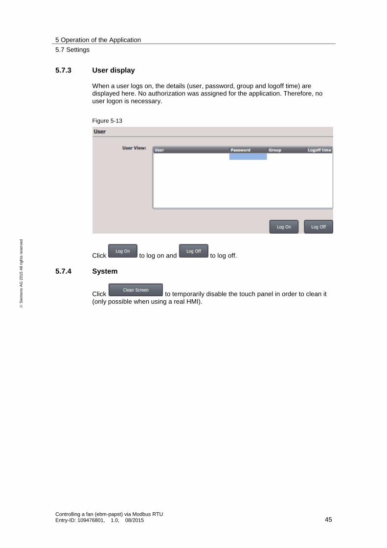
5.7.3 User display
When a user logs on, the details (user, password, group and logoff time) are displayed here. No authorization was assigned for the application. Therefore, no user logon is necessary.
Figure 5-13
Click to log on and to log off.
5.7.4 System
Click to temporarily disable the touch panel in order to clean it (only possible when using a real HMI).

6 Related Literature
Controlling a fan (ebm-papst) via Modbus RTU Entry-ID: 109476801, 1.0, 08/2015 46
S
iem
en
s A
G 2
01
5 A
ll ri
gh
ts r
ese
rve
d
6 Related Literature
Table 6-1
Topic Title / Link
\1\ Siemens Industry Online Support
http://support.industry.siemens.com
\2\ Download page of this entry
https://support.industry.siemens.com/cs/ww/en/view/109476801
\3\ How can you read input words in the address range from 9999 to 65535 with the SIMATIC S7-1200 via Modbus RTU?
https://support.industry.siemens.com/cs/ww/en/view/109474481
\4\ Service Pack 1 for SIMATIC STEP 7 V13 incl. PLCSIM (TIA Portal)
https://support.industry.siemens.com/cs/ww/en/view/105825934
\5\ Updates for STEP 7 V13 SP1 and WinCC V13 SP1
https://support.industry.siemens.com/cs/ww/en/view/109311724
\6\ Firmware updates for SIMATIC S7-1200 CPUs
https://support.industry.siemens.com/cs/ww/en/ps/13685/dl
\7\ Firmware update V2.1.0 for CM 1241
https://support.industry.siemens.com/cs/ww/en/view/108819199
\8\ Manual: SIMATIC S7 S7-1200 Programmable controller
https://support.industry.siemens.com/cs/ww/en/view/107623221
\9\ Manual: STEP 7 Basic V13 SP1
https://support.industry.siemens.com/cs/ww/en/view/109054417
\10\ Ebm-papst website http://www.ebmpapst.com/en/index.php
\11\ Operating instructions M3G112GA5271
img.ebmpapst.com/products/manuals/M3G112GA5271-BA-ENG.pdf

7 Contact
Controlling a fan (ebm-papst) via Modbus RTU Entry-ID: 109476801, 1.0, 08/2015 47
S
iem
en
s A
G 2
01
5 A
ll ri
gh
ts r
ese
rve
d
7 Contact If you have questions regarding compatible fans (e.g.
MODBUS parameter specification for “ebm-papst series 84 / 112 / 150 / 200” V5.00 or
passwords required to write protected holding registers),
please contact:
ebm-papst Mulfingen GmbH & Co. KG Bachmühle 2 D - 74673 Mulfingen Telephone: +49 7938 81-0
mailto: [email protected]
8 History
Table 8-1
Version Date Modifications
V1.0 08/2015 First version


