Embed Size (px)
Citation preview

APPLICANT: Alcatel-Lucent EXHIBIT 11 AS5ONEBTS-27
Page 1 of 17
EXHIBIT 11
TEST REPORT
This test report presents the measurement data required by the Commission for certifying the Class II
Permissive Change of the Alcatel-Lucent 1900 RRH 2x60 Distributed Base Station, subject of this
application, for LTE application and operation in the domestic PCS A, B, C, D, E and F bands (1930-
1990MHz), E-UTRAN Band II, under AS5ONEBTS-27.
As stated before, the distributed wireless RRH base station system is comprised of two separate modules 1)
the BBU and 2) the RRH. These two modules are interconnected by CPRI though optic fiber or metallic
coax cables. All RF functionality is contained in the RRH, including transceiver, power amplifier and
transmitting and receiving filters. The BBU provides the digital I and Q baseband signals, plus the timing
reference signal to the RRH. The BBU and RRH units can be co-located or remotely located.
The 1900 LTE RRH 2x60W has two antenna ports and supports transmit diversity and/or 2x2 MIMO
operation. The 1900 LTE RRH 2x60W can provide up to 60 Watts (47.8dBm) per LTE carrier (5MHz or
10MHz bandwidth carriers), 60 Watts (47.8dBm) per port and 120 Watts (50.8dBm) per RRH at the base
station transmitting antenna terminals. The 1900 LTE RRH 2x60W is powered by -48VDC and available in
indoor and outdoor versions.
As stated before, the hardware of the 1900 LTE RRH is identical to that of the 1900 UMTS RRH. In 1900
LTE RRH, there are no modifications in the transmitting and receiving frequency ranges, the basic carrier
frequency determining circuitry, the basic modulation circuit, the network interface circuitry and the major
RF components (transmitter and power amplifier) which were certified under AS5ONEBTS-27 for the
1900 UMTS RRH. Therefore, only the characteristics impacted by LTE technology were evaluated.
All testing results submitted in this report were performed on the -48VDC 1900 2x60W LTE RRH during
the period of November 30~ December 7, 2012. The above 1900 2x60W LTE RRH passed FCC Part 15
Class A radiated emissions requirements.
The measurement results have demonstrated that Alcatel-Lucent 1900 2x60W LTE RRH is in full
compliance with the Rules of the Commission.

APPLICANT: Alcatel-Lucent EXHIBIT 11 AS5ONEBTS-27
Page 2 of 17
SUBEXHIBIT 11.1
Section 2.1033 (c)(14) REQUIRED MEASUREMENT DATA
The required measurement data is presented in the following exhibits as follows:
SUBEXHIBIT 11.2 Section 2.1046 Measurements Required: RF Power Output
SUBEXHIBIT 11.3 Section 2.1047 Modulation Characteristics
SUBEXHIBIT 11.4 Section 2.1049, 24.238 Measurements Required: Occupied Bandwidth
and Out-of-Band Emissions
SUBEXHIBIT 11.5 Sections 2.1051, 24.238 Measurements Required: Spurious Emissions at
Antenna Terminals
SUBEXHIBIT 11.6 Sections 2.1053, 24.238 Measurements Required: Field Strength of
Spurious Radiation
SUBEXHIBIT 11.8 Section 2.947 List of Test Equipment Used

APPLICANT: Alcatel-Lucent EXHIBIT 11 AS5ONEBTS-27
Page 3 of 17
SUBEXHIBIT 11.2
Section 2.1046 MEASUREMENT REQUIRED: RF POWER OUTPUT
This test is a measurement of the total RF power level transmitted at the antenna-transmitting terminal (J4),
as shown in the accompanying test set-up diagram. The radio was tuned to a channel which is transmitting
in the 1930-1990 MHz frequency band. The power level of the base station was calibrated to allow the base
station to operate at the manufacturer’s maximum rated mean power level, i.e., +47.8dBm (60W) per
carrier for LTE and +47.8 dBm (60W) per port at the antenna-transmitting terminal.
For LTE, the RF power output with QPSK, 16QAM and 64QAM modulation were measured respectively.
Power measurements were made with a Power Meter in the average mode. The test set-up for conducting
the RF power output measurement is shown in the following figure. Before the testing was started, the Base
Station was given a sufficient “warm-up” period as required.
The maximum rated mean power at the antenna transmitting terminal was measured for a single carrier
(both 5MHz and 10MHz bandwidth) with LTE technology across the PCS band 1930-1990MHz. The RF
power output measured for each configuration was shown as “Ref Lvl” in the plots provided in SubExhibit
11.4.
For 5MHz bandwidth carrier, two carriers which correspond to the lowest and highest carriers in each A, B
and C bands and one carrier in each D, E and F bands were measured with QPSK, 16QAM and 64QAM
modulations, respectively.
For 10MHz bandwidth carrier, two carriers which are near the low band edge and the high band edge in
each A, B and C bands were measured with QPSK, 16QAM and 64QAM modulations, respectively.
The Peak-to-Average Power Ratio (PAPR) has also been evaluated as well per KDB 971168 for both
5MHz bandwidth carrier and 10MHz bandwidth carrier with QPSK, 16QAM and 64QAM modulations,
respectively. The PAPR values of all carriers measured are below 13dB.
Results:
The maximum rated mean RF power outputs of the Alcatel-Lucent LTE 2x60W 1900 RRH at its antenna
transmitting terminals across the PCS frequency band 1930 – 1990 MHz measured are 60W (+47.8 dBm)
per carrier and 60W (+47.8 dBm) per port, within ±1dB derivation, and are in full compliance with the
Rules of the Commission.

APPLICANT: Alcatel-Lucent EXHIBIT 11 AS5ONEBTS-27
Page 4 of 17
FIGURE 11.2.1 TEST SET-UP FOR MEASUREMENT OF
RADIO FREQUENCY POWER OUTPUT
I/Q, Timing
Signal
Digital Base Band Unit
Power Meter
with Power Sensor
and RF Directional
Coupler and RF
Attenuator
Transceiver
LTE 1900
2x60W RRH
Power Amplifier
Tx/Rx Filter

APPLICANT: Alcatel-Lucent EXHIBIT 11 AS5ONEBTS-27
Page 5 of 17
SUBEXHIBIT 11.3
Section 2.1047 MEASUREMENT REQUIRED: MODULATION CHARACTERISTICS
The 1900 2x60W LTE RRH supports LTE technology. The LTE utilizes Orthogonal Frequency Division
Multiplex (OFDM) modulation technique, where the data is distributed over a large number of closely
spaced orthogonal subcarriers. The subcarriers are modulated with conventional modulation scheme, such
as QPSK, 16QAM and 64QAM.
In LTE, the modulation characteristics for QPSK, 16QAM and 64QAM modulations are measured.
The measurement was performed for QPSK, 16QAM and 64QAM, respectively, where the carrier power
level was adjusted to the rated maximum mean power +47.8dBm (60W) at the output terminal,
The measurements were performed at the antenna transmitting terminal of the base station system with an
Agilent N9020A MXA Signal Analyzer which was calibrated in accordance with ISO 9001 process.
The test set-up diagram is given in the Figure 11.3.1, where the Agilent N9020A MXA used the external
signals from the base station as its trigger source and time reference.
Results:
Figure 11.3.2 shows three representative screen plots of the modulation measurement at 1987.5MHz C
band for a 5MHz LTE carrier, in QPSK, 16QAM and 64QAM modulations, respectively. Figure 11.3.3
shows three representative screen plots of the modulation measurement at 1985MHz C band for a 10MHz
LTE carrier, in QPSK, 16QAM and 64QAM modulations, respectively. They are in compliance with the
Rules of the Commission for measurement requirement for modulation characteristics of the LTE 1900
2x60W RRH.

APPLICANT: Alcatel-Lucent EXHIBIT 11 AS5ONEBTS-27
Page 6 of 17
FIGURE 11.3.1 TEST SET-UP FOR MEASUREMENT OF MODULATION ACCURACY,
OCCUPIED BANDWIDTH AND OUT-OF-BAND EMISSIONS
RF Tx/Rx Filter
&
Power Amplifier
BBU
Signal Analyzer and RF
Attenuators and/or RF
High Pass Filter
1900 RRH
Timing Signal
I/Q
Transceiver EXT REF
Trigger

APPLICANT: Alcatel-Lucent EXHIBIT 11 AS5ONEBTS-27
Page 7 of 17
FIGURE 11.3.2 SCREEN PLOTS OF MODULATION MEASUREMENT AT 1987.50 MHZ, C
BAND, 5MHZ LTE WITH QPSK, 16QAM AND 64QAM MODULATIONS

APPLICANT: Alcatel-Lucent EXHIBIT 11 AS5ONEBTS-27
Page 8 of 17
FIGURE 11.3.3 SCREEN PLOTS OF MODULATION MEASUREMENT AT 1985 MHZ, C BAND,
10MHZ LTE WITH QPSK, 16QAM AND 64QAM MODULATIONS

APPLICANT: Alcatel-Lucent EXHIBIT 11 AS5ONEBTS-27
Page 9 of 17

APPLICANT: Alcatel-Lucent EXHIBIT 11 AS5ONEBTS-27
Page 10 of 17
SUBEXHIBIT 11.4
Section 2.1049 MEASUREMENT REQUIRED: OCCUPIED BANDWIDTH AND OUT-OF-BAND
EMISSIONS
The 1900 LTE 2x60W RRH transmits in the domestic 1900 Band (Tx: 1930-1990 MHz and Rx: 1850-1910
MHz) with LTE and 2x60W.
The two 60MHz bandwidth PCS spectrum is divided into 6 blocks (A, B, C, D, E and F) as shown in the
following table.
Table 11.4.1 PCS Bands
PCS Blocks Tx Frequency
(MHz)
Rx Frequency
(MHz)
Bandwidth
(MHz)
A 1930 - 1945 1850 - 1865 15
B 1950 - 1965 1870 - 1885 15
C 1975 - 1990 1895 - 1910 15
D 1945 - 1950 1865 - 1870 5
E 1965 - 1970 1885 - 1890 5
F 1970 - 1975 1890 - 1895 5
The 1900 LTE RRH 2x60W Distributed Base station system supports one-carrier and multiple-carrier
configurations per transmitting path with LTE technology. However, the current software release supports
one 5MHz or one 10MHz LTE single carrier per transmitting path only.
The occupied bandwidth and out-of-band emissions measurements were made at the antenna transmitting
terminal (J4) for one 5 MHz LTE carrier on the two channels which correspond to the lowest and highest
available LTE channels in each of the PCS A, B and C frequency bands with QPSK, 16QAM and 64QAM
modulations, respectively. At each of the carrier frequencies, the carrier power level at the antenna terminal
was adjusted to the maximum rated mean power +47.8 dBm (60W).
The minimum emission requirements and the setting of measurement equipment for the occupied
bandwidth measurement of a 1900 carrier were specified in FCC Part 24.238. The FCC’s requirements are
tabulated in the following table, where MIMO requirement/margin is not included.
Table 11.4.2 FCC Part 24.238 Transmitter Unwanted Emission Limits
Frequency Required Minimum
Attenuation below the Mean
Carrier Power P
Minimum Resolution
Bandwidth of Spectrum
Analyzer
1MHz Bands Immediately
Outside the Transmitting
Frequency Band
(43 + P dBW) dBc 50kHz for 5MHz
carrier and 100kHz for
10MHz carrier
Outside the above Frequency
Range
(43 + P dBW) dBc 1 MHz
The requirement of FCC Part 24.238 was used as the required emission limit mask in the LTE
measurement.
The measurements were performed with a Rohde & Schwarz EMI Receiver, which was calibrated in
accordance with ISO 9001 process. The test set-up diagram is same as the one shown in the Figure 11.3.1.

APPLICANT: Alcatel-Lucent EXHIBIT 11 AS5ONEBTS-27
Page 11 of 17
For the 99% occupied bandwidth measurement, the spectrum analyzer was set with a 200 kHz resolution
bandwidth and 20 MHz span.
For the out-of-band emissions measurement, the spectrum analyzer was set with a 40MHz span. The
emissions outside the above span were evaluated in Measurement Required: Out-of-block Spurious
Conducted Emissions.
For a 5MHz LTE carrier measurement, the spectrum analyzer was set with a 50 kHz resolution bandwidth
as shown in the plot of the occupied bandwidth measurement attached in the following pages. The top of
the spectrum analyzer display reticule, i.e., Ref Lvl, was set to the maximum mean output power of the
LTE carrier if measured with a resolution bandwidth greater than the carrier bandwidth 5 MHz. Thus the
maximum mean output power of the LTE carrier, measured with a 50 kHz resolution bandwidth, aligns
with the top of the spectrum analyzer display reticule (Ref Lvl) minus 20dB for a 5MHz carrier. The 20 dB
offset for a 5MHz LTE carrier was due to the fact that 10 log (50kHz/5MHz) = -20 dB.
For a 10MHz LTE carrier measurement, the spectrum analyzer was set with a 100 kHz resolution
bandwidth as shown in the plots of the occupied bandwidth measurement attached in the following pages.
The top of the spectrum analyzer display reticule, i.e., Ref Lvl, was set to the maximum mean output power
of the LTE carrier if measured with a resolution bandwidth greater than the carrier bandwidth 10 MHz.
Thus the maximum mean output power of the LTE carrier, measured with a 100 kHz resolution bandwidth,
aligns with the top of the spectrum analyzer display reticule (Ref Lvl) minus 20dB for a 10MHz carrier.
The 20 dB offset for a 10MHz LTE carrier was due to the fact that 10 log (100kHz/10MHz) = -20 dB.
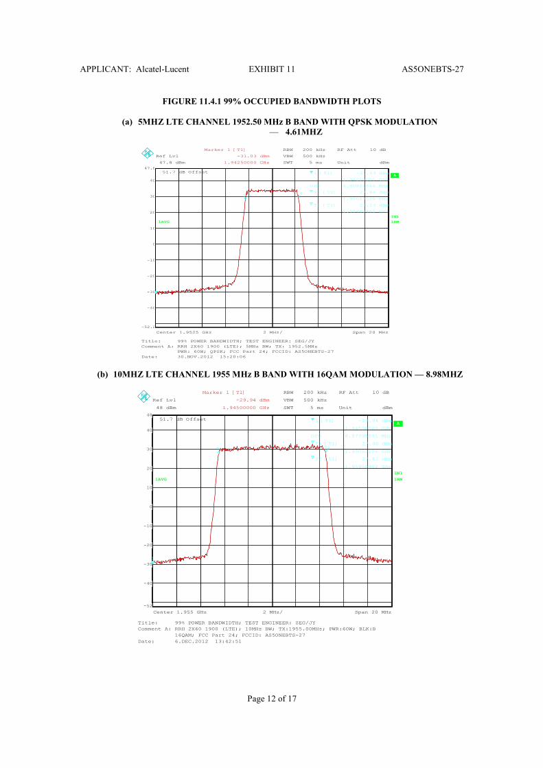
Two 99% Occupied Bandwidth plots were submitted which have the largest bandwidth among all the
modulations QPSK, 16QAM and 64 QAM evaluated for a 5MHz LTE carrier and a 10MHz LTE carrier,
respectively.
One emission plot is submitted for each 5MHz carrier and 10MHz carrier, respectively, which has the least
margin among all PCS channels evaluated with QPSK, 16QAM or 64QAM modulations. The limits
specified in FCC Part 24.238 are displayed in the plots.
Results:
From the occupied bandwidth and out-of-band plots attached in the following, it can be seen that all the
waveforms are under the required FCC emission mask with more than 3dB margin. The measurement
results demonstrate the full compliance with the Rules of the Commission at the lowest, middle and highest
channels of PCS band.
APPLICANT: Alcatel-Lucent EXHIBIT 11 AS5ONEBTS-27
Page 12 of 17
FIGURE 11.4.1 99% OCCUPIED BANDWIDTH PLOTS
(a) 5MHZ LTE CHANNEL 1952.50 MHz B BAND WITH QPSK MODULATION
— 4.61MHZ
RBW 200 kHz
VBW 500 kHz
SWT 5 ms
51.7 dB Offset A
IN1
1RM
Unit dBm
1RM1AVG
Center 1.9525 GHz Span 20 MHz2 MHz/
Ref Lvl
47.8 dBm
Ref Lvl
47.8 dBm
RF Att 10 dB
-40
-30
-20
-10
0
10
20
30
40
-52.2
47.8
1
T1T2
Marker 1 [T1]
-31.03 dBm
1.94250000 GHz
1 [T1] -31.03 dBm
1.94250000 GHz
OPB 4.60921844 MHz
T1 [T1] 27.84 dBm
1.95019539 GHz
T2 [T1] 29.13 dBm
1.95480461 GHz
Title: 99% POWER BANDWIDTH; TEST ENGINEER: SEG/JY
Comment A: RRH 2X60 1900 (LTE); 5MHz BW; TX: 1952.5MHz
PWR: 60W; QPSK; FCC Part 24; FCCID: AS5ONEBTS-27
Date: 30.NOV.2012 15:20:06
(b) 10MHZ LTE CHANNEL 1955 MHz B BAND WITH 16QAM MODULATION — 8.98MHZ
RBW 200 kHz
VBW 500 kHz
SWT 5 ms
51.7 dB Offset A
IN1
1RM
Unit dBm
1RM
RF Att 10 dB
1AVG
Ref Lvl
48 dBm
Ref Lvl
48 dBm
2 MHz/Center 1.955 GHz Span 20 MHz
-40
-30
-20
-10
0
10
20
30
40
-52
48
1
T1 T2
Marker 1 [T1]
-29.94 dBm
1.94500000 GHz
1 [T1] -29.94 dBm
1.94500000 GHz
OPB 8.97795591 MHz
T1 [T1] 27.40 dBm
1.95053106 GHz
T2 [T1] 27.82 dBm
1.95950902 GHz
Title: 99% POWER BANDWIDTH; TEST ENGINEER: SEG/JY
Comment A: RRH 2X60 1900 (LTE); 10MHz BW; TX:1955.00MHz; PWR:60W; BLK:B
16QAM; FCC Part 24; FCCID: AS5ONEBTS-27
Date: 6.DEC.2012 13:42:51

APPLICANT: Alcatel-Lucent EXHIBIT 11 AS5ONEBTS-27
Page 13 of 17
FIGURE 11.4.2 OCCUPIED BANDWIDTH AND OUT-OF-BAND EMISSIONS PLOTS
(a) LTE, B BAND, 1952.50MHZ, 5MHZ, 60W/C, 16QAM
RBW 50 kHz
VBW 300 kHz
SWT 40 ms
51.7 dB Offset A
IN1
1RM
Unit dBm
1RM
Center 1.9525 GHz Span 40 MHz4 MHz/
Ref Lvl
47.8 dBm
Ref Lvl
47.8 dBm
RF Att 10 dB
1AVG
-40
-30
-20
-10
0
10
20
30
40
-52.2
47.8
LIMIT CHECK : PASSED
D1 27.8 dBm
1900
Title: OCCUPIED BANDWIDTH; TEST ENGINEER: SEG/JY
Comment A: RRH 2X60 1900 (LTE); 5MHz BW; TX: 1952.5MHz
PWR: 60W; 16QAM; FCC Part 24; FCCID: AS5ONEBTS-27
Date: 30.NOV.2012 15:43:00
(b) LTE, C BAND, 1985.0MHZ, 10MHZ, 60W/C, 64QAM
RBW 100 kHz
VBW 300 kHz
SWT 10 ms
51.7 dB Offset A
IN1
1RM
Unit dBm
Center 1.985 GHz Span 40 MHz4 MHz/
Ref Lvl
48 dBm
Ref Lvl
48 dBm
RF Att 10 dB
1RM1AVG
-40
-30
-20
-10
0
10
20
30
40
-52
48
LIMIT CHECK : PASSED
D1 28 dBm
190010M
Title: OCCUPIED BANDWIDTH; TEST ENGINEER: SEG/JY
Comment A: RRH 2X60 1900 (LTE); 10MHz BW; TX: 1985.00MHz PWR:60W; BLK:C
64QAM; FCC Part 24; FCCID: AS5ONEBTS-27
Date: 6.DEC.2012 17:18:58

APPLICANT: Alcatel-Lucent EXHIBIT 11 AS5ONEBTS-27
Page 14 of 17
SUBEXHIBIT 11.5
Section 2.1051 MEASUREMENT REQUIRED: SPURIOUS EMISSIONS AT THE ANTENNA
TERMINALS
The out-of-block spurious emissions at the antenna transmitting terminal were investigated from 10 MHz to
the 10th harmonic of the carrier or 20 GHz, per Section 2.1057(a)(1).
The carrier setup and configurations are same as in Sub-exhibit 11.4.
The emission limitations and the setting of measurement equipment for the unwanted emissions
measurement of 5MHz or 10MHz LTE carrier were specified in 24.238 and provided in Sub-exhibit 11.4.
For the mean output power of +47.8 dBm (60 W) at J4, the required spurious emissions attenuation per (43
+ P dBW) dBc, is 60.8dBc. FCC CFR 47, Sections 2.1051 and 2.1057(c) specify that the spurious
emissions attenuated more than 20 dB below the permissible value need not be reported. So the reportable
limit is –80.8 dBc.
The measurements were performed with a Rohde & Schwarz EMI Receiver, which was calibrated in
accordance with ISO 9001 process. The test set-up diagram is given in the Figure 11.3.1.
The carrier power level at the antenna transmitting terminal was calibrated before the conducted spurious
emissions testing for each test.
The spectrum analyzer was set to a 1MHz resolution bandwidth. The r.m.s detector was used.
The spurious emissions in the frequency range of 10MHz to 20GHz are well under the required emission
limit with more than 23dB margins for all QPSK, 16QAM and 64QAM modulations evaluated. Therefore,
there are no reportable emissions.
Results:
The out-of-block spurious emissions of the Alcatel-Lucent LTE 1900 RRH2x60W in the entire spectrum
investigated (10MHz to 20GHz) are under the required emission limit with sufficient margins. The
measurement results demonstrate that the subject of the application is in full compliance with the Rules of
the Commission.

APPLICANT: Alcatel-Lucent EXHIBIT 11 AS5ONEBTS-27
Page 15 of 17
SUBEXHIBIT 11.6
Section 2.1053 MEASUREMENT REQUIRED: FIELD STRENGTH OF SPURIOUS RADIATION
The field strength measurements of radiated spurious emissions were made in a FCC (Site Registration
Number: 515091) and IC (Filing Number: 6933F-5) registered three meter semi-anechoic chamber AR-5
which is maintained by Alcatel-Lucent in Murray Hill, New Jersey.
The -48VDC LTE 1900 2x60W RRH was investigated from 30 MHz to the 10th harmonic of the carrier or
20 GHz, per Section 2.1057(a)(1). The equipment under test (EUT) was configured as in the normal mode
of the installation and operation. The recommendations of ANSI C63.4–2009 were followed for EUT
testing setup and cabling.
The base station was configured to transmit one 5MHz LTE carrier on each Tx1 and Tx2 with the
maximum mean power of 60W each. The test models used for configuring LTE carriers were described in
Sub-exhibit 11.4. All carriers were transmitting to non-radiating 50 Ω resistive loads.
The emission limitations and the setting of measurement equipment for the conducted spurious emissions
measurement of a 1900 carrier were specified in 24.238 and shown in Sub-Exhibit 11.4.
By using the relation between the electric field strength of an ideal dipole and its excitation power given in
Reference Data for Radio Engineers, page 676, 4th edition, ITT Corp., the emission limit calculated equals
Frequency of Emission
(MHz)
Separation Distance
(m)
E
(dBµµµµV/m)
Detector/RBW
10-20,000 3 84.1 Average/1MHz
The field strength of radiated spurious emissions measured was determined by
E (dBµV/m) = Vmeas (dBµV) + Cable Loss (dB) + Antenna Factor (dB1/m).
Sections 2.1051 and 2.1057(c) specify that the spurious emissions attenuated more than 20 dB below the
permissible value need not be reported. Therefore, the reportable limit plus 3dB for MIMO operation at 3
meter is 61.1 dBµV/m.
All the measurement equipment used, including antennas, was calibrated in accordance with ISO 9001
process. The EUT setup diagram is given in the Figure 11.6.1.
The spurious emissions evaluated are well under the required reportable emissions limit specified in
Section 24.238 for all QPSK, 16QAM and 64QAM modulations evaluated. Therefore, there are no
reportable emissions.
Results:
Over the frequency spectrum investigated (30MHz to 20GHz), no reportable radiated spurious emissions
were detected. The measurement results of the Alcatel-Lucent LTE 1900 2x60W RRH, subject of this
application, demonstrate the full compliance with the Rules of the Commission.

APPLICANT: Alcatel-Lucent EXHIBIT 11 AS5ONEBTS-27
Page 16 of 17
FIGURE 11.6.1 EUT FOR MEASUREMENT OF RADIATED SPURIOUS EMISSIONS
Chamber
50 Ω Load
RF Tx/Rx Filters
&
Power Amplifier
BBU
RRH
Timing
and
I/Q
Signals
Transceiver

APPLICANT: Alcatel-Lucent EXHIBIT 11 AS5ONEBTS-27
Page 17 of 17
SUBEXHIBIT 11.7
Section 2.947 LISTING OF TEST EQUIPMENT USED
Equipment Manufacturer Model Serial No. Calibrated
Date
Due Cal.
Date
Power Meter HP 437B 3125U21135 10/2/2012 10/2/2013
Power Sensor HP 8481A US372994629 9/5/2012 9/5/2013
EMI Test Receiver
(20Hz to 40 GHz)
Rohde &
Schwarz
ESIB40 100101 5/23/2012 5/23/2013
EMI Test Receiver
(20Hz to 40 GHz)
Rohde &
Schwarz
ESIB40 100100 3/28/2012 3/28/2013
MXA Agilent N9020A MY50510383 4/07/2011 4/07/2013
Spectrum Analyzer 9kHz-
26.5GHz
Agilent E7405A MY45110440 3/2/2012 3/2/2013
Attenuator 5dB (5W) Weinschel 2-6 BX3432 1/23/2012 1/23/2013
Attenuator (100 W) Weinschel 47-30-34, E796 BX1061 9/27/2012 9/27/2013
Attenuator (150W) Weinschel 66-20-34, E 816 BW7319 9/27/2012 9/27/2013
PCS High Pass Filter Trilithic 5HC2850/1805
0-1.8-KK
200113078 NA NA
Directional Coupler HP 778D, E372 18300 N/A N/A
Bilogical Antenna 25-
2000MHz
A.H. Systems SAS-521-2 458 12/27/2011 12/27/2012
Double Ridged Horn Ant. 1-
18GHz
EMCO 3115 9909-5914 9/12/2012 9/12/2014
Double Ridged Horn Ant.
18-40GHz
EMC Test
System
3116 2537 9/27/2011 12/27/2012
Pre-amplifier 1-26.5GHz Hewlett-Packard 8449B 3008A01267 7/23/2012 7/23/2013
Pre-amplifier 9kHz-1GHz Sonoma
Instrument
310N 186750 7/23/2012 7/23/2013