Embed Size (px)
DESCRIPTION
service manual
Citation preview
Service Source
K
LaserWriter 8500

Service Source
K
Overview
LaserWriter 8500
Overview About This Overview - 1
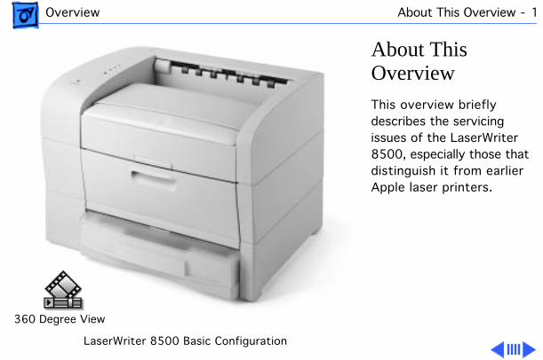
About This Overview
This overview briefly describes the servicing issues of the LaserWriter 8500, especially those that distinguish it from earlier Apple laser printers.
LaserWriter 8500 Basic Configuration
360 Degree View
Overview General - 2
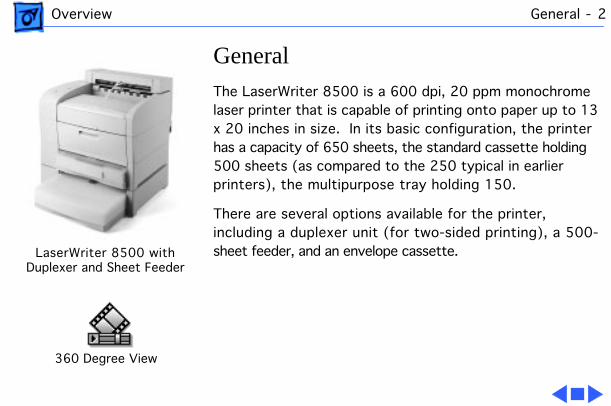
General
The LaserWriter 8500 is a 600 dpi, 20 ppm monochrome laser printer that is capable of printing onto paper up to 13 x 20 inches in size. In its basic configuration, the printer has a capacity of 650 sheets, the standard cassette holding 500 sheets (as compared to the 250 typical in earlier printers), the multipurpose tray holding 150.
There are several options available for the printer, including a duplexer unit (for two-sided printing), a 500-sheet feeder, and an envelope cassette.
360 Degree View
LaserWriter 8500 withDuplexer and Sheet Feeder
Overview Duplexer - 3
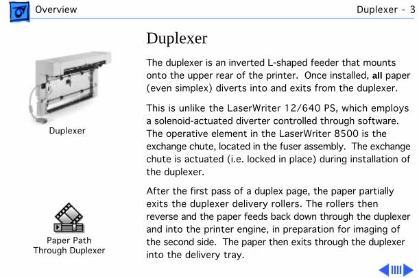
Duplexer
The duplexer is an inverted L-shaped feeder that mounts onto the upper rear of the printer. Once installed,
all
paper (even simplex) diverts into and exits from the duplexer.
This is unlike the LaserWriter 12/640 PS, which employs a solenoid-actuated diverter controlled through software. The operative element in the LaserWriter 8500 is the exchange chute, located in the fuser assembly. The exchange chute is actuated (i.e. locked in place) during installation of the duplexer.
After the first pass of a duplex page, the paper partially exits the duplexer delivery rollers. The rollers then reverse and the paper feeds back down through the duplexer and into the printer engine, in preparation for imaging of the second side. The paper then exits through the duplexer into the delivery tray.
Duplexer
Paper PathThrough Duplexer
Overview Paper Path - 4
The duplexer derives its power from the printer engine but has its own motor to generate mechanical drive.
Offset Function
The duplexer has a job separation feature that allows print jobs to be stacked offset (i.e. staggered left-to-right) in the delivery tray. Job separation is set in the Apple Printer Utility.
Note
: Due to cost considerations, the offset function has been incorporated into the duplexer instead of the printer engine. Offsetting and duplex printing are otherwise unrelated to one another.
The offset motor in the duplexer generates the mechanical drive for offsetting paper.

Overview Sheet Feeder - 5
Sheet Feeder
As with the LaserWriter 16/600 PS and LaserWriter 12/640 PS designs, the sheet feeder fits squarely beneath the printer to form a dual front-loading cassette arrangement. Unlike those models, however, you can stack two feeders beneath the printer, for a total auxiliary capacity of 1000 sheets. Also unlike those models, the sheet feeder and the engine use identical cassettes in the LaserWriter 8500.
The sheet feeder derives its power and mechanical drive from the printer engine.
Sheet Feeder
Overview Form Factor - 6
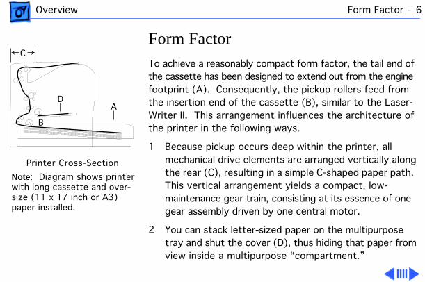
Form Factor
To achieve a reasonably compact form factor, the tail end of the cassette has been designed to extend out from the engine footprint (A). Consequently, the pickup rollers feed from the insertion end of the cassette (B), similar to the Laser-Writer II. This arrangement influences the architecture of the printer in the following ways.
1 Because pickup occurs deep within the printer, all mechanical drive elements are arranged vertically along the rear (C), resulting in a simple C-shaped paper path. This vertical arrangement yields a compact, low-maintenance gear train, consisting at its essence of one gear assembly driven by one central motor.
2 You can stack letter-sized paper on the multipurpose tray and shut the cover (D), thus hiding that paper from view inside a multipurpose “compartment.”
A
B
D
C
Printer Cross-Section
Note : Diagram shows printerwith long cassette and over-size (11 x 17 inch or A3)paper installed.
Overview Form Factor - 7
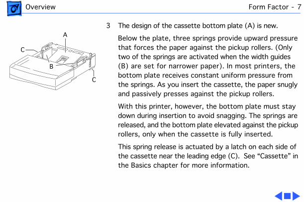
3 The design of the cassette bottom plate (A) is new.
Below the plate, three springs provide upward pressure that forces the paper against the pickup rollers. (Only two of the springs are activated when the width guides (B) are set for narrower paper). In most printers, the bottom plate receives constant uniform pressure from the springs. As you insert the cassette, the paper snugly and passively presses against the pickup rollers.
With this printer, however, the bottom plate must stay down during insertion to avoid snagging. The springs are released, and the bottom plate elevated against the pickup rollers, only when the cassette is fully inserted.
This spring release is actuated by a latch on each side of the cassette near the leading edge (C). See “Cassette” in the Basics chapter for more information.
A
C
C
B
Overview Paper Orientation - 8
Paper Orientation
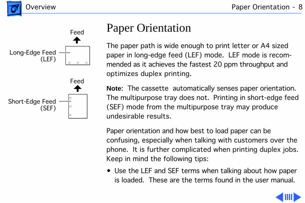
The paper path is wide enough to print letter or A4 sized paper in long-edge feed (LEF) mode. LEF mode is recom-mended as it achieves the fastest 20 ppm throughput and optimizes duplex printing.
Note
: The cassette automatically senses paper orientation. The multipurpose tray does not. Printing in short-edge feed (SEF) mode from the multipurpose tray may produce undesirable results.
Paper orientation and how best to load paper can be confusing, especially when talking with customers over the phone. It is further complicated when printing duplex jobs. Keep in mind the following tips:
• Use the LEF and SEF terms when talking about how paper is loaded. These are the terms found in the user manual.
Short-Edge Feed(SEF)
Long-Edge Feed(LEF)
Feed
Feed
Overview Paper Orientation - 9
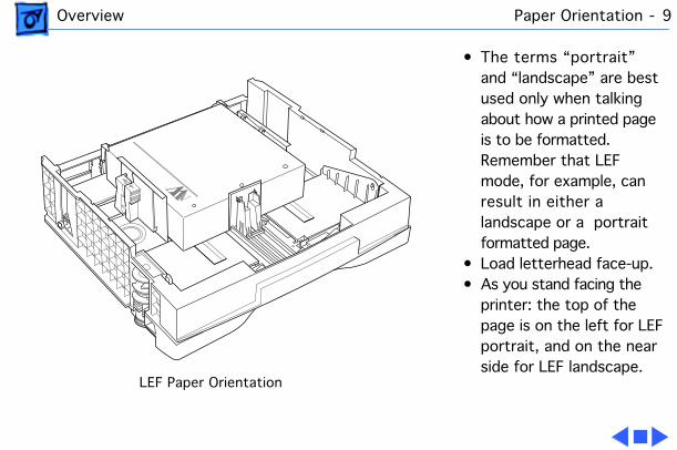
• The terms “portrait” and “landscape” are best used only when talking about how a printed page is to be formatted. Remember that LEF mode, for example, can result in either a landscape or a portrait formatted page.
• Load letterhead face-up.• As you stand facing the
printer: the top of the page is on the left for LEF portrait, and on the near side for LEF landscape.
LEF Paper Orientation
Overview Service Test Page - 10
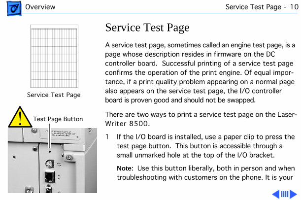
Service Test Page
A service test page, sometimes called an engine test page, is a page whose description resides in firmware on the DC controller board. Successful printing of a service test page confirms the operation of the print engine. Of equal impor-tance, if a print quality problem appearing on a normal page also appears on the service test page, the I/O controller board is proven good and should not be swapped.
There are two ways to print a service test page on the Laser-Writer 8500.
1 If the I/O board is installed, use a paper clip to press the test page button. This button is accessible through a small unmarked hole at the top of the I/O bracket.
Note
: Use this button liberally, both in person and when troubleshooting with customers on the phone. It is your
Service Test Page
Test Page Button
Overview Service Test Page - 11
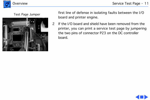
first line of defense in isolating faults between the I/O board and printer engine.
2 If the I/O board and shield have been removed from the printer, you can print a service test page by jumpering the two pins of connector P23 on the DC controller board.
Test Page Jumper
Overview RAM Memory - 12
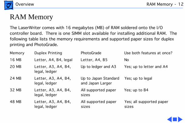
RAM Memory
The LaserWriter comes with 16 megabytes (MB) of RAM soldered onto the I/O controller board. There is one SIMM slot available for installing additional RAM. The following table lists the memory requirements and supported paper sizes for duplex printing and PhotoGrade.
Memory Duplex Printing PhotoGrade Use both features at once?
16 MB Letter, A4, B4, legal Letter, A4, B5 No
20 MB Letter, A3, A4, B4, Up to ledger and A3 Yes; up to letter and A4legal, ledger
24 MB Letter, A3, A4, B4, Up to Japan Standard Yes; up to legal legal, ledger and Japan Larger
32 MB Letter, A3, A4, B4, All supported paper Yes; up to B4 legal, ledger sizes
48 MB Letter, A3, A4, B4, All supported paper Yes; all supported paperlegal, ledger sizes sizes
Overview SIMM Sizes and Speeds - 13
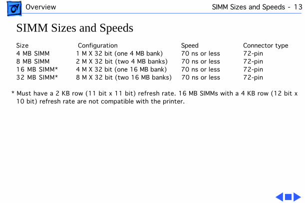
SIMM Sizes and Speeds
Size Configuration Speed Connector type4 MB SIMM 1 M X 32 bit (one 4 MB bank) 70 ns or less 72-pin8 MB SIMM 2 M X 32 bit (two 4 MB banks) 70 ns or less 72-pin16 MB SIMM* 4 M X 32 bit (one 16 MB bank) 70 ns or less 72-pin32 MB SIMM* 8 M X 32 bit (two 16 MB banks) 70 ns or less 72-pin
* Must have a 2 KB row (11 bit x 11 bit) refresh rate. 16 MB SIMMs with a 4 KB row (12 bit x 10 bit) refresh rate are not compatible with the printer.
Overview Miscellaneous - 14
Miscellaneous
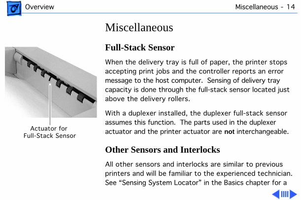
Full-Stack Sensor
When the delivery tray is full of paper, the printer stops accepting print jobs and the controller reports an error message to the host computer. Sensing of delivery tray capacity is done through the full-stack sensor located just above the delivery rollers.
With a duplexer installed, the duplexer full-stack sensor assumes this function. The parts used in the duplexer actuator and the printer actuator are
not
interchangeable.
Other Sensors and Interlocks
All other sensors and interlocks are similar to previous printers and will be familiar to the experienced technician. See “Sensing System Locator” in the Basics chapter for a
Actuator for Full-Stack Sensor
Overview Miscellaneous - 15
comprehensive diagram.
There is also a mechanical interlock that disengages the fuser assembly drive train when the top cover is open (to facilitate removal of paper jams). See “Top Housing and Xerographics” in the Basics chapter.
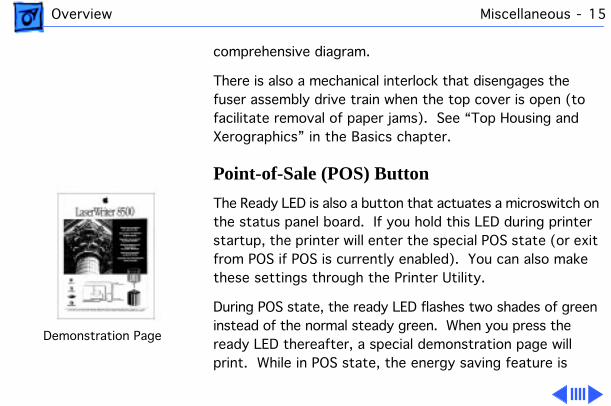
Point-of-Sale (POS) Button
The Ready LED is also a button that actuates a microswitch on the status panel board. If you hold this LED during printer startup, the printer will enter the special POS state (or exit from POS if POS is currently enabled). You can also make these settings through the Printer Utility.
During POS state, the ready LED flashes two shades of green instead of the normal steady green. When you press the ready LED thereafter, a special demonstration page will print. While in POS state, the energy saving feature is
Demonstration Page
Overview Miscellaneous - 16
disabled, but in all other ways, the printer is network-aware and will perform just as it does in ready state.
Voltage-Specific Parts
Four parts in the printer are available in both 110V and 220V versions:
• Power supply• Fuser assembly• Transport chute assembly• DC controller board
Note
: The DC controller board, though universal in previous printers, is not in the LaserWriter 8500.
The second version of this board satisfies European Economic Community requirements and has made possible some localization of controller board firmware (default paper size for the multipurpose tray, for example).
Overview Miscellaneous - 17
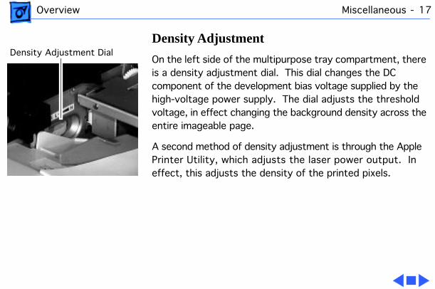
Density Adjustment
On the left side of the multipurpose tray compartment, there is a density adjustment dial. This dial changes the DC component of the development bias voltage supplied by the high-voltage power supply. The dial adjusts the threshold voltage, in effect changing the background density across the entire imageable page.
A second method of density adjustment is through the Apple Printer Utility, which adjusts the laser power output. In effect, this adjusts the density of the printed pixels.
Density Adjustment Dial
Service Source
K
Basics
LaserWriter 8500
Basics Function of Main Components - 1
Function of Main Components
This topic describes the function of the following components of the LaserWriter 8500.•Cassette•Cassette Feed Components•Manual Feed Components•Paper Transportation•Fusing and Paper Exit•Frame and Drive•Top Cover and Xerographics•Electrical
Cassette
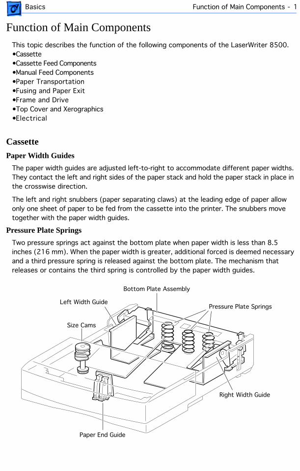
Paper Width Guides
The paper width guides are adjusted left-to-right to accommodate different paper widths. They contact the left and right sides of the paper stack and hold the paper stack in place in the crosswise direction.
The left and right snubbers (paper separating claws) at the leading edge of paper allow only one sheet of paper to be fed from the cassette into the printer. The snubbers move together with the paper width guides.
Pressure Plate Springs
Two pressure springs act against the bottom plate when paper width is less than 8.5 inches (216 mm). When the paper width is greater, additional forced is deemed necessary and a third pressure spring is released against the bottom plate. The mechanism that releases or contains the third spring is controlled by the paper width guides.
Bottom Plate Assembly
Left Width Guide
Right Width Guide
Size Cams
Pressure Plate Springs
Paper End Guide
Basics Function of Main Components - 2
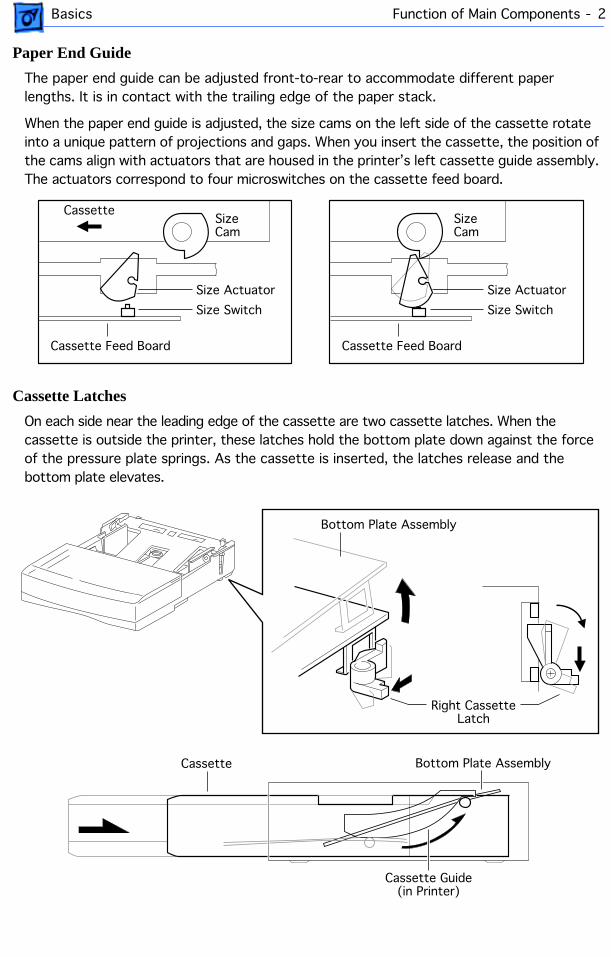
Paper End Guide
The paper end guide can be adjusted front-to-rear to accommodate different paper lengths. It is in contact with the trailing edge of the paper stack.
When the paper end guide is adjusted, the size cams on the left side of the cassette rotate into a unique pattern of projections and gaps. When you insert the cassette, the position of the cams align with actuators that are housed in the printer’s left cassette guide assembly. The actuators correspond to four microswitches on the cassette feed board.
Cassette Latches
On each side near the leading edge of the cassette are two cassette latches. When the cassette is outside the printer, these latches hold the bottom plate down against the force of the pressure plate springs. As the cassette is inserted, the latches release and the bottom plate elevates.
Size Actuator
Size Switch
Cassette Feed Board
Cassette
Size Actuator
Size Switch
Cassette Feed Board
Size Cam
Size Cam
Bottom Plate Assembly
Right Cassette Latch
Bottom Plate AssemblyCassette
Cassette Guide(in Printer)
Basics Function of Main Components - 3
Cassette Feed Components
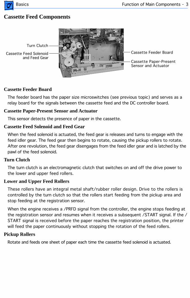
Cassette Feeder Board
The feeder board has the paper size microswitches (see previous topic) and serves as a relay board for the signals between the cassette feed and the DC controller board.
Cassette Paper-Present Sensor and Actuator
This sensor detects the presence of paper in the cassette.
Cassette Feed Solenoid and Feed Gear
When the feed solenoid is actuated, the feed gear is releases and turns to engage with the feed idler gear. The feed gear then begins to rotate, causing the pickup rollers to rotate. After one revolution, the feed gear disengages from the feed idler gear and is latched by the pawl of the feed solenoid.
Turn Clutch
The turn clutch is an electromagnetic clutch that switches on and off the drive power to the lower and upper feed rollers.
Lower and Upper Feed Rollers
These rollers have an integral metal shaft/rubber roller design. Drive to the rollers is controlled by the turn clutch so that the rollers start feeding from the pickup area and stop feeding at the registration sensor.
When the engine receives a /PRFD signal from the controller, the engine stops feeding at the registration sensor and resumes when it receives a subsequent /START signal. If the /START signal is received before the paper reaches the registration position, the printer will feed the paper continuously without stopping the rotation of the feed rollers.
Pickup Rollers
Rotate and feeds one sheet of paper each time the cassette feed solenoid is actuated.
Cassette Feeder Board
Turn Clutch
Cassette Feed Solenoid
Cassette Paper-Present Sensor and Actuator
and Feed Gear
Basics Function of Main Components - 4
Manual Feed Components
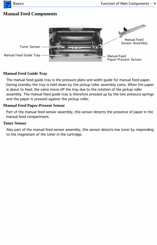
Manual Feed Guide Tray
The manual feed guide tray is the pressure plate and width guide for manual feed paper. During standby the tray is held down by the pickup roller assembly cams. When the paper is about to feed, the cams move off the tray due to the rotation of the pickup roller assembly. The manual feed guide tray is therefore pressed up by the two pressure springs and the paper is pressed against the pickup roller.
Manual Feed Paper-Present Sensor
Part of the manual feed sensor assembly, this sensor detects the presence of paper in the manual feed compartment.
Toner Sensor
Also part of the manual feed sensor assembly, this sensor detects low toner by responding to the magnetism of the toner in the cartridge.
Manual Feed
Manual Feed Guide Tray
Sensor AssemblyToner Sensor
Manual FeedPaper-Present Sensor
Basics Function of Main Components - 5
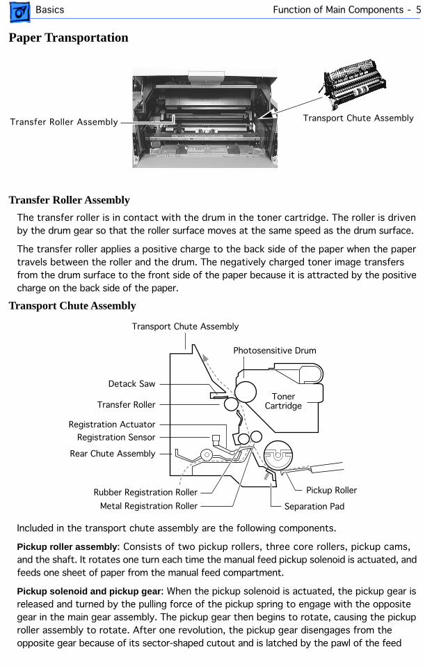
Paper Transportation
Transfer Roller Assembly
The transfer roller is in contact with the drum in the toner cartridge. The roller is driven by the drum gear so that the roller surface moves at the same speed as the drum surface.
The transfer roller applies a positive charge to the back side of the paper when the paper travels between the roller and the drum. The negatively charged toner image transfers from the drum surface to the front side of the paper because it is attracted by the positive charge on the back side of the paper.
Transport Chute Assembly
Included in the transport chute assembly are the following components.
Pickup roller assembly
: Consists of two pickup rollers, three core rollers, pickup cams, and the shaft. It rotates one turn each time the manual feed pickup solenoid is actuated, and feeds one sheet of paper from the manual feed compartment.
Pickup solenoid and pickup gear
: When the pickup solenoid is actuated, the pickup gear is released and turned by the pulling force of the pickup spring to engage with the opposite gear in the main gear assembly. The pickup gear then begins to rotate, causing the pickup roller assembly to rotate. After one revolution, the pickup gear disengages from the opposite gear because of its sector-shaped cutout and is latched by the pawl of the feed
Transfer Roller Assembly Transport Chute Assembly
Rubber Registration Roller
Rear Chute Assembly
Metal Registration Roller Separation Pad
Pickup Roller
TonerCartridge
Photosensitive Drum
Transport Chute Assembly
Detack Saw
Transfer Roller
Registration Sensor
Registration Actuator
Basics Function of Main Components - 6
solenoid.
Separation pad assembly
: Prevents extra sheets of paper from being fed by the friction between the paper and the rubber of the separation pad.
Rear chute assembly
: Guides the paper fed from the cassette between the metal and rubber registration rollers.
Metal registration roller and rubber registration roller
: The rotation of these rollers is controlled by means of the registration clutch assembly so as to register the paper with the image on the drum.
Registration sensor
: Detects the arrival and departure of the paper at the registration position.
Transfer roller bearing
: Applies the transfer voltage from the high-voltage power supply to the transfer roller assembly.
Detack saw
: Imparts a negative charge to the back side of the paper, partially neutralizing the positive charges, so that the paper can peel off the drum.
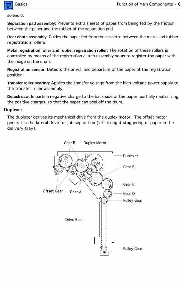
Duplexer
The duplexer derives its mechanical drive from the duplex motor. The offset motor generates the lateral drive for job separation (left-to-right staggering of paper in the delivery tray).
Duplex Motor
Duplexer
Gear B
Gear B
Gear C
Gear D
Pulley Gear
Offset Gear Gear A
Pulley Gear
Drive Belt
Basics Function of Main Components - 7
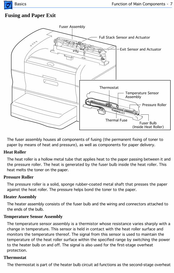
Fusing and Paper Exit
The fuser assembly houses all components of fusing (the permanent fixing of toner to paper by means of heat and pressure), as well as components for paper delivery.
Heat Roller
The heat roller is a hollow metal tube that applies heat to the paper passing between it and the pressure roller. The heat is generated by the fuser bulb inside the heat roller. This heat melts the toner on the paper.
Pressure Roller
The pressure roller is a solid, sponge rubber-coated metal shaft that presses the paper against the heat roller. The pressure helps bond the toner to the paper.
Heater Assembly
The heater assembly consists of the fuser bulb and the wiring and connectors attached to the ends of the bulb.
Temperature Sensor Assembly
The temperature sensor assembly is a thermistor whose resistance varies sharply with a change in temperature. This sensor is held in contact with the heat roller surface and monitors the temperature thereof. The signal from this sensor is used to maintain the temperature of the heat roller surface within the specified range by switching the power to the heater bulb on and off. The signal is also used for the first-stage overheat protection.
Thermostat
The thermostat is part of the heater bulb circuit ad functions as the second-stage overheat
Full Stack Sensor and Actuator
Exit Sensor and Actuator
Thermostat
Temperature Sensor Assembly
Fuser Bulb(Inside Heat Roller)
Thermal Fuse
Pressure Roller
Fuser Assembly
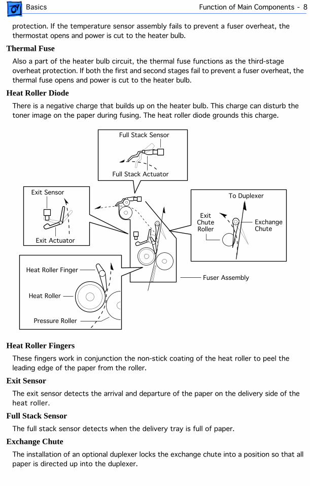
Basics Function of Main Components - 8
protection. If the temperature sensor assembly fails to prevent a fuser overheat, the thermostat opens and power is cut to the heater bulb.
Thermal Fuse
Also a part of the heater bulb circuit, the thermal fuse functions as the third-stage overheat protection. If both the first and second stages fail to prevent a fuser overheat, the thermal fuse opens and power is cut to the heater bulb.
Heat Roller Diode
There is a negative charge that builds up on the heater bulb. This charge can disturb the toner image on the paper during fusing. The heat roller diode grounds this charge.
Heat Roller Fingers
These fingers work in conjunction the non-stick coating of the heat roller to peel the leading edge of the paper from the roller.
Exit Sensor
The exit sensor detects the arrival and departure of the paper on the delivery side of the heat roller.
Full Stack Sensor
The full stack sensor detects when the delivery tray is full of paper.
Exchange Chute
The installation of an optional duplexer locks the exchange chute into a position so that all paper is directed up into the duplexer.
Exit Sensor
Exit Actuator
ExchangeChute
ExitChuteRoller
Full Stack Sensor
Full Stack Actuator
To Duplexer
Heat Roller
Pressure Roller
Heat Roller FingerFuser Assembly

Basics Function of Main Components - 9
Frame and Drive
Main Motor
Generates all the drive power for the printer and optional sheet feeder.
Main Gear Assembly
Distributes drive power from the main motor to the fuser assembly, toner cartridge, paper handling gear assembly, registration clutch assembly, and pickup gear.
Paper Handling Gear Assembly
Transfers the drive power from the main gear assembly to the feed idler gear and to a second gear within the main gear assembly.
Registration Clutch Assembly
An electromagnetic clutch that switches the drive power on and off to the two registration rollers at a specified time after the registration sensor has detected the arrival of the paper. This clutch actuates momentarily after the paper arrives at the registration rollers to allow the feed rollers to remove any skew induced during paper feed.
Main Motor
Main Gear Assembly
Paper-Handling Gear Assembly
Registration ClutchAssembly
Basics Function of Main Components - 10
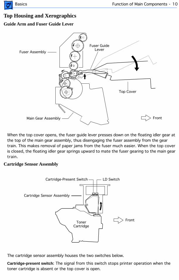
Top Housing and Xerographics
Guide Arm and Fuser Guide Lever
When the top cover opens, the fuser guide lever presses down on the floating idler gear at the top of the main gear assembly, thus disengaging the fuser assembly from the gear train. This makes removal of paper jams from the fuser much easier. When the top cover is closed, the floating idler gear springs upward to mate the fuser gearing to the main gear train.
Cartridge Sensor Assembly
The cartridge sensor assembly houses the two switches below.
Cartridge-present switch
: The signal from this switch stops printer operation when the toner cartridge is absent or the top cover is open.
Main Gear Assembly
Fuser Assembly
Fuser GuideLever
Top Cover
Front
Cartridge-Present Switch LD Switch
Cartridge Sensor Assembly
TonerCartridge
Front
Basics Function of Main Components - 11
Laser-diode (LD) switch
: This switch opens the laser diode circuit when the toner cartridge is absent or the top cover is open. The LD switch protects users against exposure to the laser light.
Toner Cartridge
The toner cartridge consists of five major components.
Photosensitive drum
: An aluminum cylinder with a surface coating of photoconductive material. The photoconductive coating holds an electrical charge, and allows the charge to flow through the thickness when exposed to light.
Bias charge roller (BCR)
: Places a uniform electrical charge on the drum surface, erasing any charging patterns remaining from the previous cycle.
Magnetic roller
: Holds a thin layer of toner on its surface and transports it to the gap between the drum and the magnet roller. Toner is supplied to the magnetic roller by two agitators inside the toner compartment.
Charging and metering (CM) blade
: Spreads a thin layer of toner on the magnetic roll and gives toner a negative charge.
Cleaning blade
: Scrapes the toner off the drum surface that is remaining after the transfer stage.
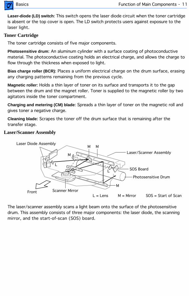
Laser/Scanner Assembly
The laser/scanner assembly scans a light beam onto the surface of the photosensitive drum. This assembly consists of three major components: the laser diode, the scanning mirror, and the start-of-scan (SOS) board.
SOS = Start of Scan
SOS Board
M = Mirror
M
M M
M
L
L
L = LensFront
Laser Diode Assembly
Photosensitive Drum
Scanner Mirror
Laser/Scanner Assembly
Basics Function of Main Components - 12
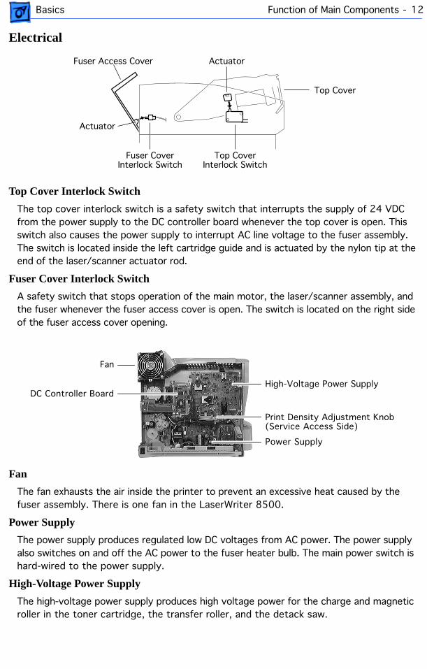
Electrical
Top Cover Interlock Switch
The top cover interlock switch is a safety switch that interrupts the supply of 24 VDC from the power supply to the DC controller board whenever the top cover is open. This switch also causes the power supply to interrupt AC line voltage to the fuser assembly. The switch is located inside the left cartridge guide and is actuated by the nylon tip at the end of the laser/scanner actuator rod.
Fuser Cover Interlock Switch
A safety switch that stops operation of the main motor, the laser/scanner assembly, and the fuser whenever the fuser access cover is open. The switch is located on the right side of the fuser access cover opening.
Fan
The fan exhausts the air inside the printer to prevent an excessive heat caused by the fuser assembly. There is one fan in the LaserWriter 8500.
Power Supply
The power supply produces regulated low DC voltages from AC power. The power supply also switches on and off the AC power to the fuser heater bulb. The main power switch is hard-wired to the power supply.
High-Voltage Power Supply
The high-voltage power supply produces high voltage power for the charge and magnetic roller in the toner cartridge, the transfer roller, and the detack saw.
Fuser Access Cover
Top Cover
Actuator
Actuator
Top CoverInterlock Switch
Fuser CoverInterlock Switch
Fan
Power Supply
High-Voltage Power SupplyDC Controller Board
Print Density Adjustment Knob(Service Access Side)

Basics Function of Main Components - 13
DC Controller Board
The DC controller board controls all printer operations. It has the following six major functions.
1. Communicates with the I/O board.
2. Communicates with the optional duplexer.
3. Receives information from the printer sensors and switches.
4. Controls the laser/scanner, fuser, and main motor.
5. Controls the printing process.
6. Distributes DC power from the power supply to other printer components.
Print Density Adjustment Knob
This knob adjusts the print density by changing the DC component of the developing bias voltage supplied by the high-voltage power supply. Turning this knob clockwise increases the print density. Turning this knob counterclockwise decreases the print density.
Print Density Adjustment Knob(User Accessible Side)
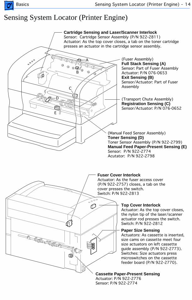
Basics Sensing System Locator (Printer Engine) - 14
Sensing System Locator (Printer Engine)
B
C
A (Fuser Assembly)Full Stack Sensing (A)Sensor: Part of Fuser AssemblyActuator: P/N 076-0653Exit Sensing (B)Sensor/Actuator: Part of Fuser Assembly
(Transport Chute Assembly)Registration Sensing (C)Sensor/Actuator: P/N 076-0652
(Manual Feed Sensor Assembly)Toner Sensing (D)Toner Sensor Assembly (P/N 922-2799)Manual Feed Paper-Present Sensing (E)Sensor: P/N 922-2774Acutator: P/N 922-2798
Cartridge Sensing and Laser/Scanner InterlockSensor: Cartridge Sensor Assembly (P/N 922-2811)Actuator: As the top cover closes, a tab on the toner cartridgepresses an actuator in the cartridge sensor assembly.
D
E
Top Cover Interlock Actuator: As the top cover closes, the nylon tip of the laser/scanner actuator rod presses the switch.Switch: P/N 922-2812
Cassette Paper-Present SensingActuator: P/N 922-2776Sensor: P/N 922-2774
Paper Size SensingActuators: As cassette is inserted, size cams on cassette meet four size actuators on left cassette guide assembly (P/N 922-2773).Switches: Size actuators press microswitches on the cassette feeder board (P/N 922-2770).
Fuser Cover Interlock Actuator: As the fuser access cover (P/N 922-2757) closes, a tab on the cover presses the switch.Switch: P/N 922-2813
Basics Sensing System Locator (Duplexer) - 15
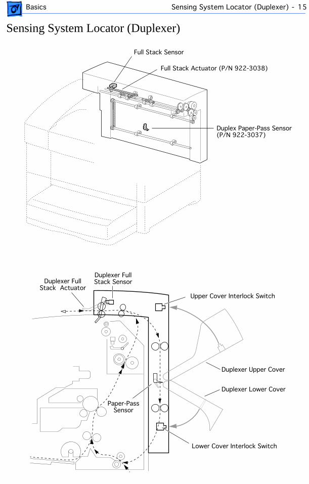
Sensing System Locator (Duplexer)
Full Stack Actuator (P/N 922-3038)
Duplex Paper-Pass Sensor(P/N 922-3037)
Full Stack Sensor
Paper-PassSensor
Duplexer Lower Cover
Duplexer Upper Cover
Upper Cover Interlock Switch
Lower Cover Interlock Switch
Duplexer Full Stack SensorDuplexer Full
Stack Actuator
Basics Wiring Diagram - 16
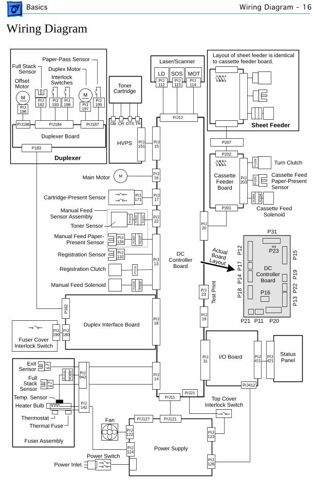
Wiring Diagram
DCController
Board
OffsetMotor
Paper-Pass Sensor
Duplex Motor
InterlockSwitches
Duplexer Board
Cassette FeederBoard
HVPS
TonerCartridge
Full Stack Sensor
Laser/Scanner
LD SOS MOT
StatusPanel
I/O Board
Test
Prin
t
Top CoverInterlock Switch
Power SupplyPower Switch
Power Inlet
Fuser Assembly
Duplex Interface Board
Manual Feed Solenoid
Manual Feed Paper-Present Sensor
Registration Sensor
Toner Sensor
Cartridge-Present Sensor
Main Motor
Fuser CoverInterlock Switch
Fan
ExitSensor
FullStack
Sensor
Temp. Sensor
Thermostat
Heater Bulb
Thermal Fuse
Registration Clutch
Manual FeedSensor Assembly
Cassette FeedPaper-PresentSensor
Cassette FeedSolenoid
P31
P21 P11 P20
P12
P17
P14
P18
P13
P22
P19
P15
Turn Clutch
Layout of sheet feeder is identical to cassette feeder board.
Duplexer
Sheet Feeder
P23ActualBoardLayout
P16
DCController
Board
P/J127 P/J121
P/J126
P/J122
P/J124
P/J14
P/J23
P/J31
P/J411
P/J123
P/J21
P/J412
P/J11
P/J421
P/J18
P/J19
P/J13
P/J134
P/J132
P/J171
P/J17
P/J16
P/J22
P/J20
P201
P202
P/J203
P207
P/J
206
P/J
205
P/J
904
P/J
204
P/J142
P/J942
P/J190
P/J180
P18
2
P/J15
P/J151
P/J112
P/J113
P/J114
P/J12
P/J187P/J184P/J186
P/J196
P/J192
P/J193
P/J198 P/J
197
P/J195
P/J
935
P/J
135
P/J
131
P/J
137
P/J
937
P/J
222
P/J
922
P/J
221
M
DB CR DTS TR
P183
Service Source
K
Specifications
LaserWriter 8500
Specifications Engine - 1
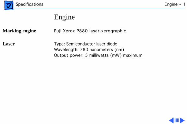
Engine
Marking engine
Fuji Xerox P880 laser-xerographic
Laser
Type: Semiconductor laser diodeWavelength: 780 nanometers (nm)Output power: 5 milliwatts (mW) maximum

Specifications Controller - 2
Controller
Microprocessor
AMD Am29040 30/60-MHz RISC microprocessor
ROM
8 megabytes (MB) of ROM (including 136 fonts)
RAM
16 MB of RAM (expandable to 48 MB). See “RAM Memory” in the Overview chapter for more information.
I/O processor
80C186 I/O processor
EEPROM
8 kilobytes (KB) parameter EEPROM
Specifications Ports - 3
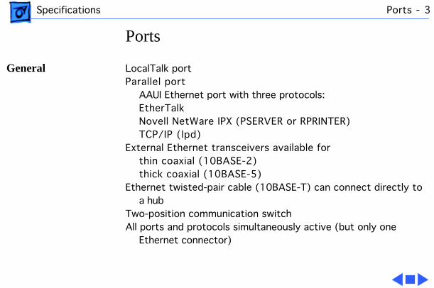
Ports
General
LocalTalk portParallel port
AAUI Ethernet port with three protocols:EtherTalkNovell NetWare IPX (PSERVER or RPRINTER)TCP/IP (lpd)
External Ethernet transceivers available forthin coaxial (10BASE-2)thick coaxial (10BASE-5)
Ethernet twisted-pair cable (10BASE-T) can connect directly to a hub
Two-position communication switchAll ports and protocols simultaneously active (but only one
Ethernet connector)
Specifications Imaging - 4
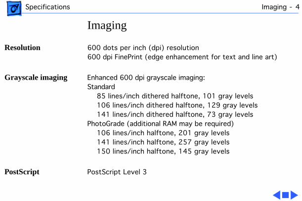
Imaging
Resolution
600 dots per inch (dpi) resolution600 dpi FinePrint (edge enhancement for text and line art)
Grayscale imaging
Enhanced 600 dpi grayscale imaging:Standard
85 lines/inch dithered halftone, 101 gray levels106 lines/inch dithered halftone, 129 gray levels141 lines/inch dithered halftone, 73 gray levels
PhotoGrade (additional RAM may be required)106 lines/inch halftone, 201 gray levels141 lines/inch halftone, 257 gray levels150 lines/inch halftone, 145 gray levels
PostScript
PostScript Level 3
Specifications Imaging - 5
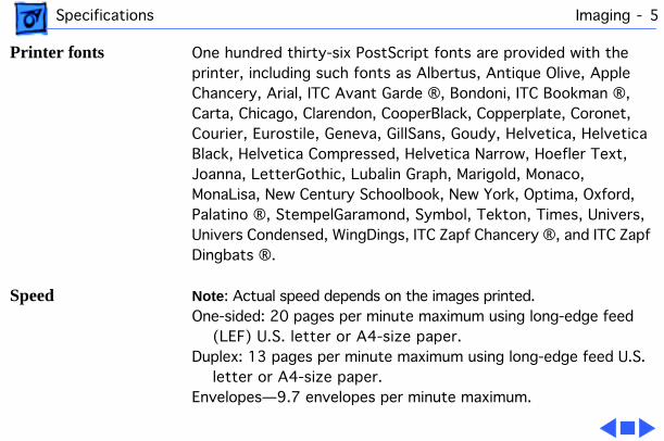
Printer fonts
One hundred thirty-six PostScript fonts are provided with the printer, including such fonts as Albertus, Antique Olive, Apple Chancery, Arial, ITC Avant Garde ®, Bondoni, ITC Bookman ®, Carta, Chicago, Clarendon, CooperBlack, Copperplate, Coronet, Courier, Eurostile, Geneva, GillSans, Goudy, Helvetica, Helvetica Black, Helvetica Compressed, Helvetica Narrow, Hoefler Text, Joanna, LetterGothic, Lubalin Graph, Marigold, Monaco, MonaLisa, New Century Schoolbook, New York, Optima, Oxford, Palatino ®, StempelGaramond, Symbol, Tekton, Times, Univers, Univers Condensed, WingDings, ITC Zapf Chancery ®, and ITC Zapf Dingbats ®.
Speed
Note
: Actual speed depends on the images printed.One-sided: 20 pages per minute maximum using long-edge feed
(LEF) U.S. letter or A4-size paper. Duplex: 13 pages per minute maximum using long-edge feed U.S.
letter or A4-size paper. Envelopes—9.7 envelopes per minute maximum.
Specifications Life Expectancy - 6
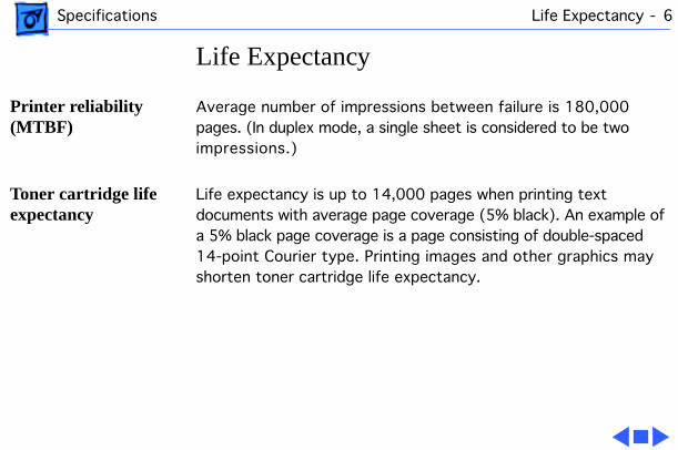
Life Expectancy
Printer reliability (MTBF)
Average number of impressions between failure is 180,000 pages. (In duplex mode, a single sheet is considered to be two impressions.)
Toner cartridge life expectancy
Life expectancy is up to 14,000 pages when printing text documents with average page coverage (5% black). An example of a 5% black page coverage is a page consisting of double-spaced 14-point Courier type. Printing images and other graphics may shorten toner cartridge life expectancy.
Specifications Printing Materials - 7
Printing Materials
Paper types
16- to 28-pound laser-quality bond (60 to 105 g/m 2 ); up to 36-pound (135 g/m 2 ) stock when fed manually through the multipurpose tray. Accepts most textured and colored stock. Accepts medium-weight photocopier transparencies and labels. Envelopes can be printed from the multipurpose tray or from the optional envelope feeder.
The paper used should not scorch, melt, transfer material, or release hazardous emissions when heated to 200° C (400° F) for 0.1 seconds.
Paper sizes and capacity
The paper cassette holds 500 sheets of 20-pound (75 g/m 2 ) paper. The multipurpose tray can hold up to 150 sheets of standard U.S. letter paper, and other paper sizes from postcard up to U.S. legal. An optional 500-sheet feeder and cassette is
Specifications Printing Materials - 8
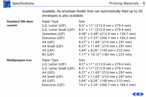
available. An envelope feeder that can automatically feed up to 50 envelopes is also available.
Standard 500-sheet cassette
Paper Type SizeU.S. Letter (LEF) 8.5" x 11" (215.9 mm x 279.4 mm)U.S. Letter Small (LEF) 8.5" x 11" (215.9 mm x 279.4 mm)Statement (LEF) 8.48" x 5.48" (215.9 mm x 139.7 mm)Executive (LEF) 10.5" x 7.25" (266.7 mm x 184.2 mm)A4 (LEF) 8.27" x 11.69" (210 mm x 297 mm)A4 Small (LEF) 8.27" x 11.69" (210 mm x 297 mm)A5 (LEF) 5.84" x 8.26" (148 mm x 210 mm)B5 (LEF) 7.17" x 10.12" (182 mm x 257 mm)
Multipurpose tray
Paper Type SizeU.S. Letter (LEF) 8.5" x 11" (215.9 mm x 279.4 mm)U.S. Letter Small (LEF) 8.5" x 11" (215.9 mm x 279.4 mm)A4 (LEF) 8.27" x 11.69" (210 mm x 297 mm)A4 Small (LEF) 8.27" x 11.69" (210 mm x 297 mm)A5 (LEF) 5.84" x 8.26" (148 mm x 210 mm)Executive (LEF) 10.5" x 7.25" (266.7 mm x 184.2 mm)
Specifications Printing Materials - 9
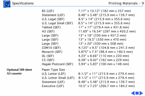
B5 (LEF) 7.17" x 10.12" (182 mm x 257 mm)Statement (LEF) 8.48" x 5.48" (215.9 mm x 139.7 mm)U.S. Legal (SEF) 8.5" x 14" (215.9 mm x 355.6 mm)U.S. Legal Small (SEF) 8.5" x 14" (215.9 mm x 355.6 mm)Tabloid (SEF) 11" x 17" (279.4 mm x 431.8 mm)A3 (SEF) 11.69" x 16.54" (297 mm x 420.2 mm)Large (SEF) 13" x 18" (330 mm x 457.2 mm)Large (SEF) 13" x 18.5" (330 mm x 470 mm)Large (SEF) 13" x 20" (330 mm x 508 mm)COM10 (SEF) 4.125" x 9.5" (104.8 mm x 241.3 mm)Monarch (SEF) 3.875" x 7.5" (98.4 mm x 190.5 mm)DL (SEF) 4.33" x 8.66" (110 mm x 220 mm)C5 (SEF) 6.38" x 9.02" (162 mm x 229 mm)Hagaki Postcard (SEF) 3.94" x 5.83" (100 mm x 148 mm)
Optional 500-sheet A3 cassette
Paper Type SizeU.S. Letter (LEF) 8-1/2" x 11" (215.9 mm x 279.4 mm)U.S. Letter Small (LEF) 8-1/2" x 11" (215.9 mm x 279.4 mm)Statement (LEF) 8.48" x 5.48" (215.9 mm x 139.7 mm)Executive (LEF) 10.5" x 7.25" (266.7 mm x 184.2 mm)
Specifications Printing Materials - 10
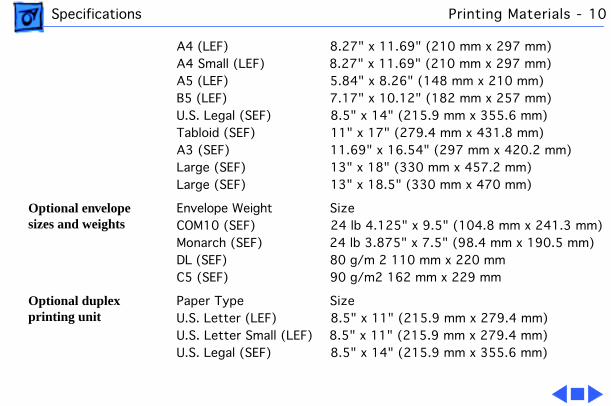
A4 (LEF) 8.27" x 11.69" (210 mm x 297 mm)A4 Small (LEF) 8.27" x 11.69" (210 mm x 297 mm)A5 (LEF) 5.84" x 8.26" (148 mm x 210 mm)B5 (LEF) 7.17" x 10.12" (182 mm x 257 mm)U.S. Legal (SEF) 8.5" x 14" (215.9 mm x 355.6 mm)Tabloid (SEF) 11" x 17" (279.4 mm x 431.8 mm)A3 (SEF) 11.69" x 16.54" (297 mm x 420.2 mm)Large (SEF) 13" x 18" (330 mm x 457.2 mm)Large (SEF) 13" x 18.5" (330 mm x 470 mm)
Optional envelope sizes and weights
Envelope Weight SizeCOM10 (SEF) 24 lb 4.125" x 9.5" (104.8 mm x 241.3 mm)Monarch (SEF) 24 lb 3.875" x 7.5" (98.4 mm x 190.5 mm)DL (SEF) 80 g/m 2 110 mm x 220 mmC5 (SEF) 90 g/m2 162 mm x 229 mm
Optional duplex printing unit
Paper Type SizeU.S. Letter (LEF) 8.5" x 11" (215.9 mm x 279.4 mm)U.S. Letter Small (LEF) 8.5" x 11" (215.9 mm x 279.4 mm)U.S. Legal (SEF) 8.5" x 14" (215.9 mm x 355.6 mm)
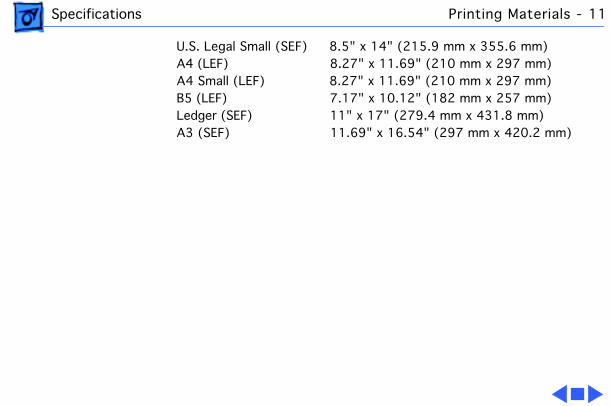
Specifications Printing Materials - 11
U.S. Legal Small (SEF) 8.5" x 14" (215.9 mm x 355.6 mm)A4 (LEF) 8.27" x 11.69" (210 mm x 297 mm)A4 Small (LEF) 8.27" x 11.69" (210 mm x 297 mm)B5 (LEF) 7.17" x 10.12" (182 mm x 257 mm)Ledger (SEF) 11" x 17" (279.4 mm x 431.8 mm)A3 (SEF) 11.69" x 16.54" (297 mm x 420.2 mm)
Specifications Dimensions - 12
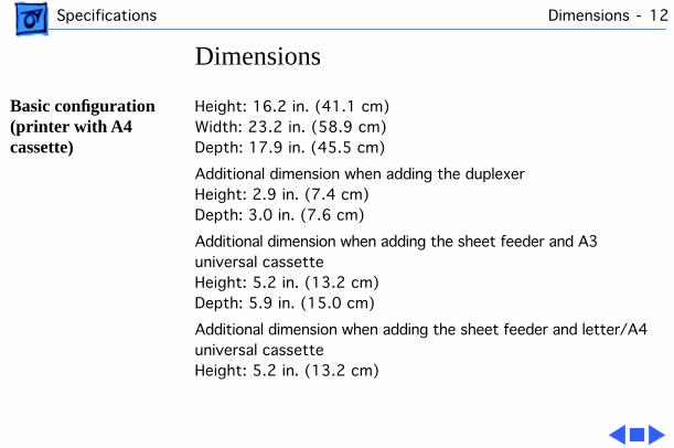
Dimensions
Basic configuration (printer with A4 cassette)
Height: 16.2 in. (41.1 cm)Width: 23.2 in. (58.9 cm)Depth: 17.9 in. (45.5 cm)
Additional dimension when adding the duplexerHeight: 2.9 in. (7.4 cm)Depth: 3.0 in. (7.6 cm)
Additional dimension when adding the sheet feeder and A3 universal cassetteHeight: 5.2 in. (13.2 cm)Depth: 5.9 in. (15.0 cm)
Additional dimension when adding the sheet feeder and letter/A4 universal cassetteHeight: 5.2 in. (13.2 cm)
Specifications Dimensions - 13
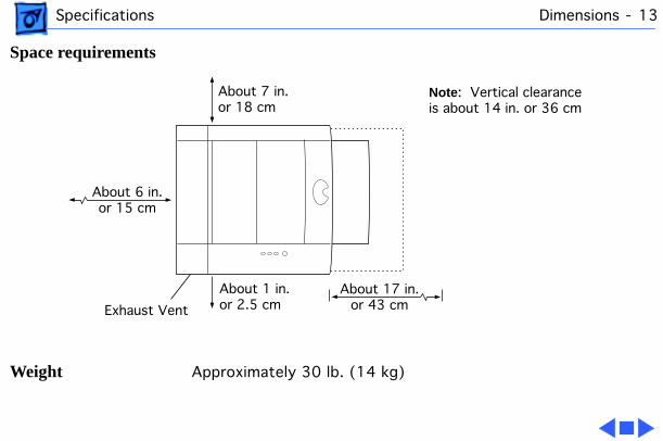
Space requirements
Weight
Approximately 30 lb. (14 kg)
About 6 in.or 15 cm
About 17 in.or 43 cm
About 7 in.or 18 cm
Exhaust Vent
Note: Vertical clearanceis about 14 in. or 36 cm
About 1 in. or 2.5 cm
Specifications Environmental - 14
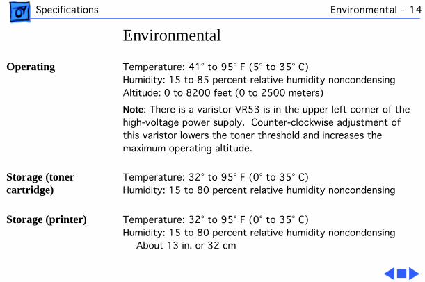
Environmental
Operating
Temperature: 41° to 95° F (5° to 35° C)Humidity: 15 to 85 percent relative humidity noncondensingAltitude: 0 to 8200 feet (0 to 2500 meters)
Note
: There is a varistor VR53 is in the upper left corner of the high-voltage power supply. Counter-clockwise adjustment of this varistor lowers the toner threshold and increases the maximum operating altitude.
Storage (toner cartridge)
Temperature: 32° to 95° F (0° to 35° C)Humidity: 15 to 80 percent relative humidity noncondensing
Storage (printer)
Temperature: 32° to 95° F (0° to 35° C)Humidity: 15 to 80 percent relative humidity noncondensing
About 13 in. or 32 cm
Specifications Environmental - 15
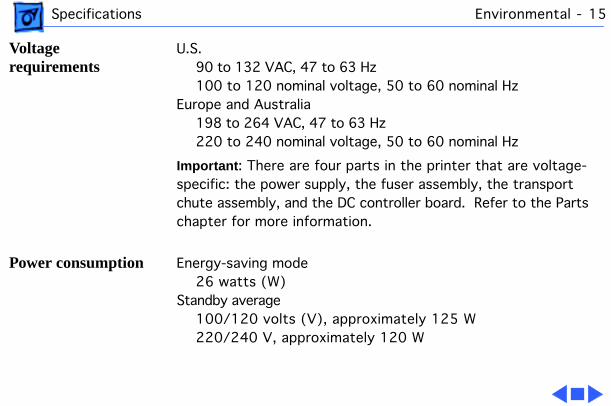
Voltage requirements
U.S.90 to 132 VAC, 47 to 63 Hz100 to 120 nominal voltage, 50 to 60 nominal Hz
Europe and Australia198 to 264 VAC, 47 to 63 Hz220 to 240 nominal voltage, 50 to 60 nominal Hz
Important
: There are four parts in the printer that are voltage-specific: the power supply, the fuser assembly, the transport chute assembly, and the DC controller board. Refer to the Parts chapter for more information.
Power consumption
Energy-saving mode26 watts (W)
Standby average100/120 volts (V), approximately 125 W220/240 V, approximately 120 W
Specifications Environmental - 16
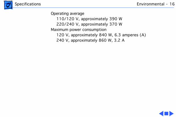
Operating average110/120 V, approximately 390 W220/240 V, approximately 370 W
Maximum power consumption120 V, approximately 840 W, 6.3 amperes (A)240 V, approximately 860 W, 3.2 A
Service Source
K
Take Apart
LaserWriter 8500
Take Apart General - 1
General
Before you begin, perform the following procedures:• Switch off power and unplug the printer• Remove duplexer and/or sheet feeder (if applicable)• Remove cassette• Remove toner cartridge
Before working on any printed circuit board, ground yourself and your equipment to an earth or building ground. Use a grounded conductive workbench mat and grounding wriststrap, and ground your equipment to the mat.
Take Apart Fuser Access Cover - 2
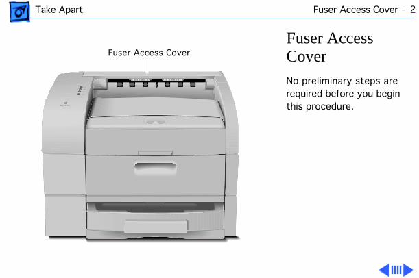
Fuser Access Cover
No preliminary steps are required before you begin this procedure.
Fuser Access Cover
Take Apart Fuser Access Cover - 3
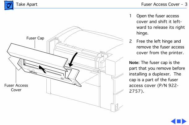
1 Open the fuser access cover and shift it left-ward to release its right hinge.
2 Free the left hinge and remove the fuser access cover from the printer.
Note
: The fuser cap is the part that you remove before installing a duplexer. The cap is a part of the fuser access cover (P/N 922-2757).
Fuser Cap
Fuser AccessCover
Take Apart Left Top Cover - 4
Left Top Cover
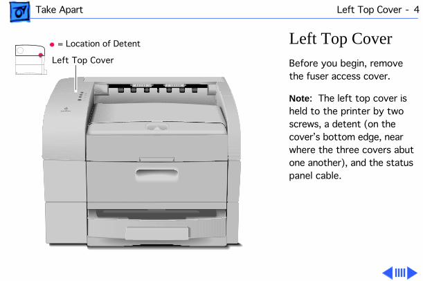
Before you begin, remove the fuser access cover.
Note
: The left top cover is held to the printer by two screws, a detent (on the cover’s bottom edge, near where the three covers abut one another), and the status panel cable.
= Location of Detent
Left Top Cover
Take Apart Left Top Cover - 5
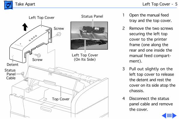
1 Open the manual feed tray and the top cover.
2 Remove the two screws securing the left top cover to the printer frame (one along the rear and one inside the manual feed compart-ment).
3 Pull out slightly on the left top cover to release the detent and rest the cover on its side atop the chassis.
4 Disconnect the status panel cable and remove the cover.
Left Top Cover
Top Cover
Screw
ScrewDetent
StatusPanelCable
Status Panel
Left Top Cover(On Its Side)
Take Apart Left Top Cover - 6
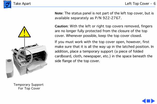
Note
: The status panel is not part of the left top cover, but is available separately as P/N 922-2767.
Caution
: With the left or right top covers removed, fingers are no longer fully protected from the closure of the top cover. Whenever possible, keep the top cover closed.
If you must work with the top cover open, however, first make sure that it is all the way up in the latched position. In addition, place a temporary support (a piece of folded cardboard, cloth, newspaper, etc.) in the space beneath the side flange of the top cover.
Temporary SupportFor Top Cover
Take Apart Left Cover Assembly - 7
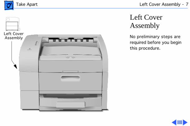
Left Cover Assembly
No preliminary steps are required before you begin this procedure.
Left Cover Assembly
Take Apart Left Cover Assembly - 8
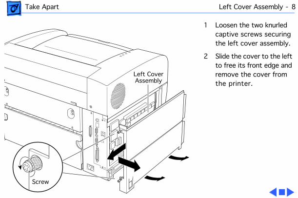
1 Loosen the two knurled captive screws securing the left cover assembly.
2 Slide the cover to the left to free its front edge and remove the cover from the printer.
Screw
Left CoverAssembly
Take Apart Front Left Cover - 9
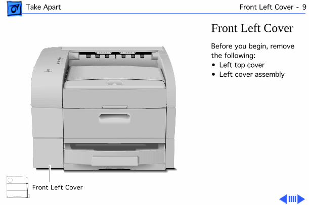
Front Left Cover
Before you begin, remove the following:• Left top cover• Left cover assembly
Front Left Cover
Take Apart Front Left Cover - 10
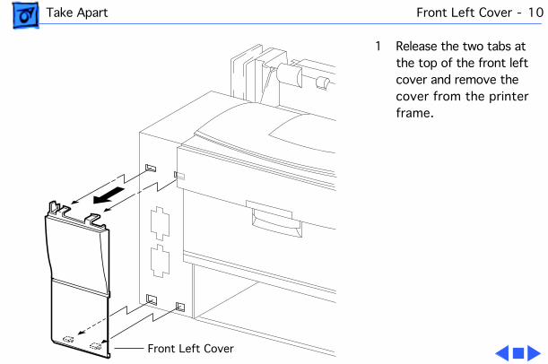
1 Release the two tabs at the top of the front left cover and remove the cover from the printer frame.
Front Left Cover
Take Apart Left Lower Cover - 11
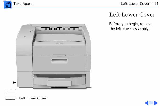
Left Lower Cover
Before you begin, remove the left cover assembly.
Left Lower Cover
Take Apart Left Lower Cover - 12
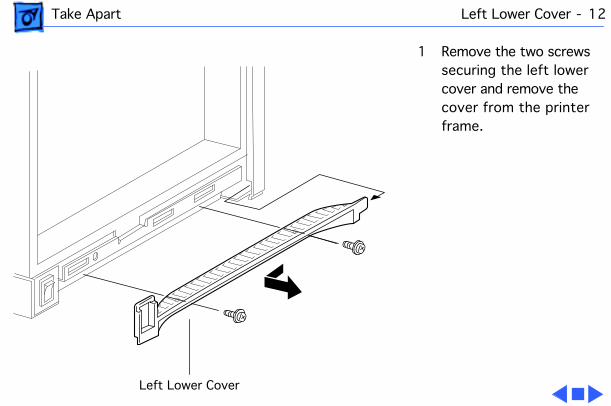
1 Remove the two screws securing the left lower cover and remove the cover from the printer frame.
Left Lower Cover
Take Apart Right Top Cover - 13
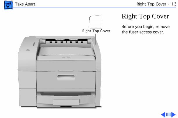
Right Top Cover
Before you begin, remove the fuser access cover.Right Top Cover
Take Apart Right Top Cover - 14
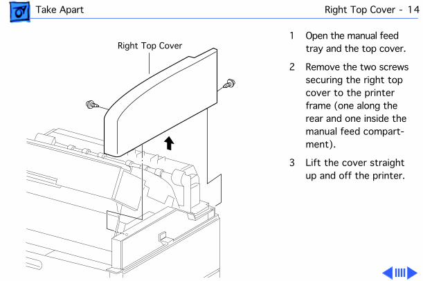
1 Open the manual feed tray and the top cover.
2 Remove the two screws securing the right top cover to the printer frame (one along the rear and one inside the manual feed compart-ment).
3 Lift the cover straight up and off the printer.
Right Top Cover
Take Apart Right Top Cover - 15
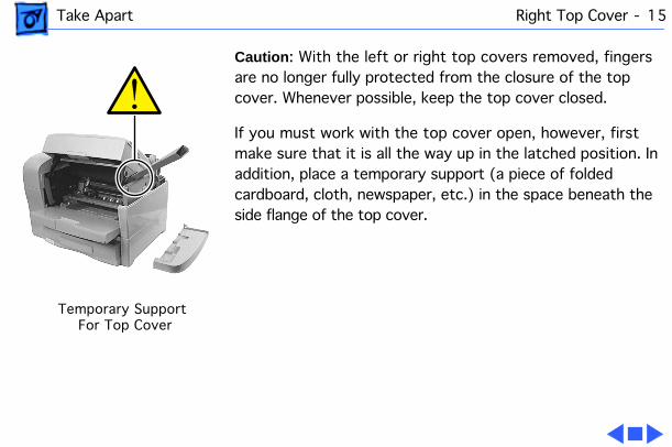
Caution
: With the left or right top covers removed, fingers are no longer fully protected from the closure of the top cover. Whenever possible, keep the top cover closed.
If you must work with the top cover open, however, first make sure that it is all the way up in the latched position. In addition, place a temporary support (a piece of folded cardboard, cloth, newspaper, etc.) in the space beneath the side flange of the top cover.
Temporary SupportFor Top Cover
Take Apart Right Cover - 16
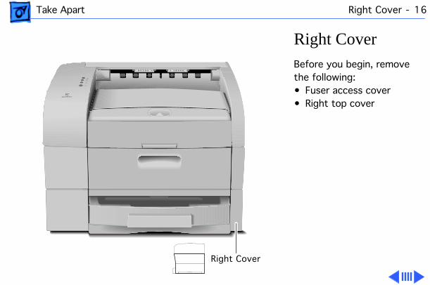
Right Cover
Before you begin, remove the following:• Fuser access cover• Right top cover
Right Cover
Take Apart Right Cover - 17
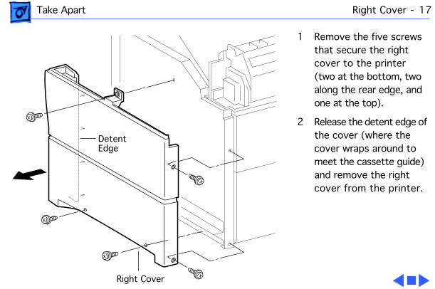
1 Remove the five screws that secure the right cover to the printer (two at the bottom, two along the rear edge, and one at the top).
2 Release the detent edge of the cover (where the cover wraps around to meet the cassette guide) and remove the right cover from the printer.
Right Cover
DetentEdge
Take Apart Exit Cover - 18
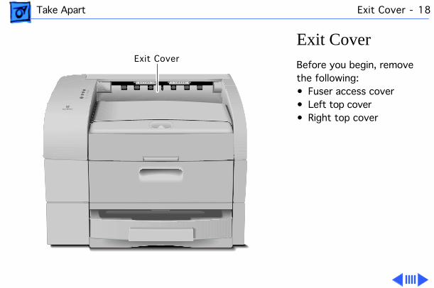
Exit Cover
Before you begin, remove the following:• Fuser access cover• Left top cover• Right top cover
Exit Cover
Take Apart Exit Cover - 19
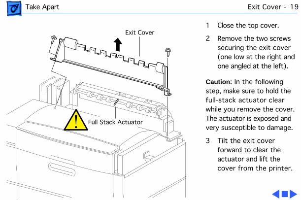
1 Close the top cover.
2 Remove the two screws securing the exit cover (one low at the right and one angled at the left).
Caution
: In the following step, make sure to hold the full-stack actuator clear while you remove the cover. The actuator is exposed and very susceptible to damage.
3 Tilt the exit cover forward to clear the actuator and lift the cover from the printer.
Exit Cover
Full Stack Actuator
Take Apart Top Cover - 20
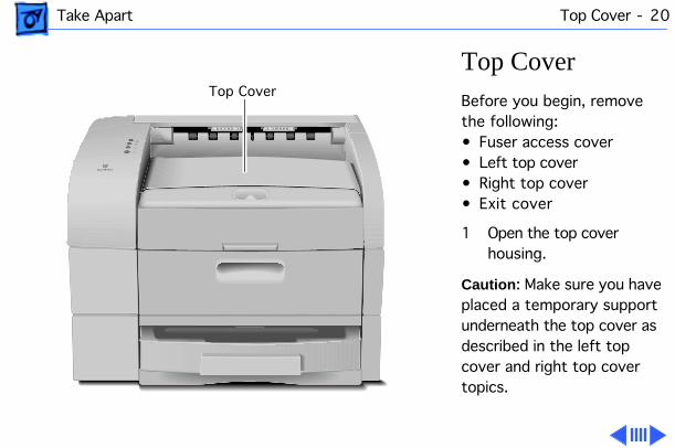
Top Cover
Before you begin, remove the following:• Fuser access cover• Left top cover• Right top cover• Exit cover
1 Open the top cover housing.
Caution
: Make sure you have placed a temporary support underneath the top cover as described in the left top cover and right top cover topics.
Top Cover
Take Apart Top Cover - 21
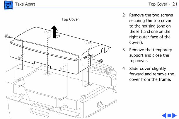
2 Remove the two screws securing the top cover to the housing (one on the left and one on the right outer face of the cover).
3 Remove the temporary support and close the top cover.
4 Slide cover slightly forward and remove the cover from the frame.
Top Cover
Take Apart Front Cover - 22
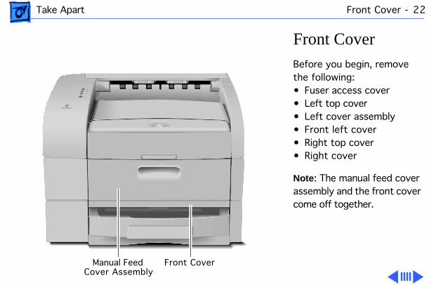
Front Cover
Before you begin, remove the following:• Fuser access cover• Left top cover• Left cover assembly• Front left cover• Right top cover• Right cover
Note
: The manual feed cover assembly and the front cover come off together.
Front CoverManual FeedCover Assembly
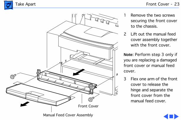
Take Apart Front Cover - 23
1 Remove the two screws securing the front cover to the chassis.
2 Lift out the manual feed cover assembly together with the front cover.
Note
: Perform step 3 only if you are replacing a damaged front cover or manual feed cover.
3 Flex one arm of the front cover to release the hinge and separate the front cover from the manual feed cover.
Front Cover
Manual Feed Cover Assembly
Take Apart Turn-In Chute - 24
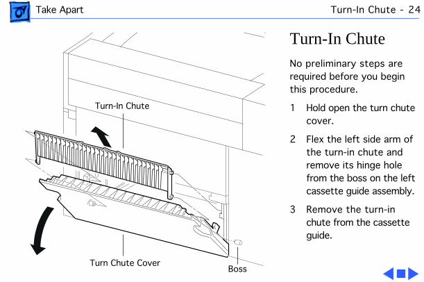
Turn-In Chute
No preliminary steps are required before you begin this procedure.
1 Hold open the turn chute cover.
2 Flex the left side arm of the turn-in chute and remove its hinge hole from the boss on the left cassette guide assembly.
3 Remove the turn-in chute from the cassette guide.
Turn-In Chute
Turn Chute CoverBoss
Take Apart Turn Chute Cover - 25
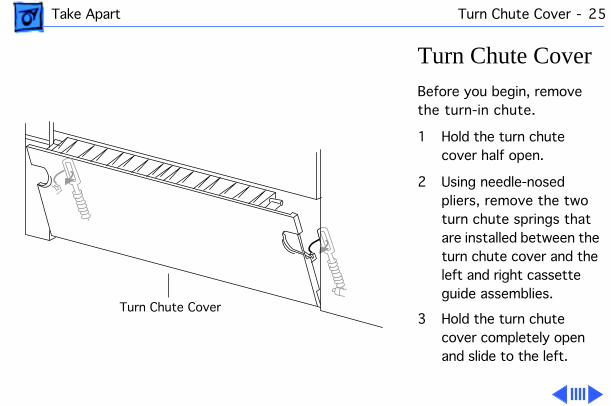
Turn Chute Cover
Before you begin, remove the turn-in chute.
1 Hold the turn chute cover half open.
2 Using needle-nosed pliers, remove the two turn chute springs that are installed between the turn chute cover and the left and right cassette guide assemblies.
3 Hold the turn chute cover completely open and slide to the left.
Turn Chute Cover
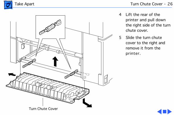
Take Apart Turn Chute Cover - 26
4 Lift the rear of the printer and pull down the right side of the turn chute cover.
5 Slide the turn chute cover to the right and remove it from the printer.
Turn Chute Cover
Take Apart Fuser Assembly - 27
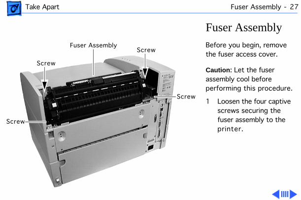
Fuser Assembly
Before you begin, remove the fuser access cover.
Caution
: Let the fuser assembly cool before performing this procedure.
1 Loosen the four captive screws securing the fuser assembly to the printer.
Screw
Screw
Screw
Fuser AssemblyScrew
Take Apart Fuser Assembly - 28
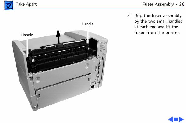
2 Grip the fuser assembly by the two small handles at each end and lift the fuser from the printer.
Handle
Handle
Take Apart I/O Board - 29
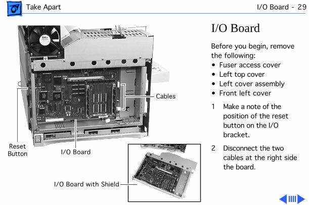
I/O Board
Before you begin, remove the following:• Fuser access cover• Left top cover• Left cover assembly• Front left cover
1 Make a note of the position of the reset button on the I/O bracket.
2 Disconnect the two cables at the right side the board.
I/O Board with Shield
I/O Board
Cables
ResetButton
Take Apart I/O Board - 30
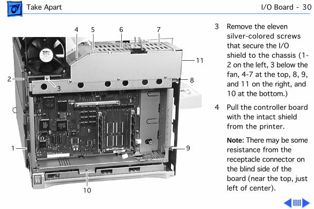
3 Remove the eleven silver-colored screws that secure the I/O shield to the chassis (1-2 on the left, 3 below the fan, 4-7 at the top, 8, 9, and 11 on the right, and 10 at the bottom.)
4 Pull the controller board with the intact shield from the printer.
Note
: There may be some resistance from the receptacle connector on the blind side of the board (near the top, just left of center).
2
1
10
9
8
7654
3
11
Take Apart I/O Board - 31
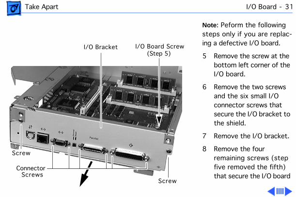
Note
: Peform the following steps only if you are replac-ing a defective I/O board.
5 Remove the screw at the bottom left corner of the I/O board.
6 Remove the two screws and the six small I/O connector screws that secure the I/O bracket to the shield.
7 Remove the I/O bracket.
8 Remove the four remaining screws (step five removed the fifth) that secure the I/O board
Screw
Screw
Connector Screws
I/O Bracket I/O Board Screw(Step 5)
Take Apart I/O Board - 32
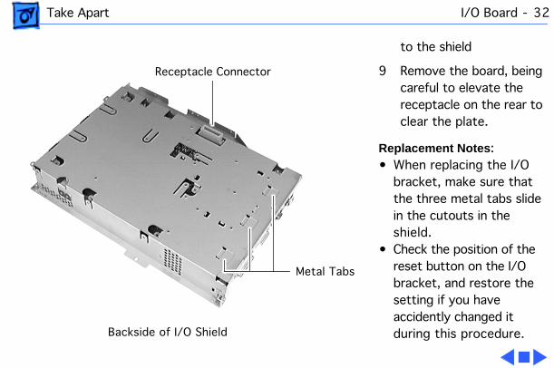
to the shield
9 Remove the board, being careful to elevate the receptacle on the rear to clear the plate.
Replacement Notes
: • When replacing the I/O
bracket, make sure that the three metal tabs slide in the cutouts in the shield.
• Check the position of the reset button on the I/O bracket, and restore the setting if you have accidently changed it during this procedure.
Receptacle Connector
Metal Tabs
Backside of I/O Shield

Take Apart Cassette Feeder Board - 33
Cassette Feeder Board
Before you begin, remove the following:• Left top cover • Left cover assembly• Front left cover • Left lower cover• I/O board
Cassette Feeder Board
Take Apart Cassette Feeder Board - 34
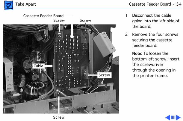
1 Disconnect the cable going into the left side of the board.
2 Remove the four screws securing the cassette feeder board.
Note
: To loosen the bottom left screw, insert the screwdriver through the opening in the printer frame.
Cassette Feeder Board Screw
Screw
Screw
Screw
Cable
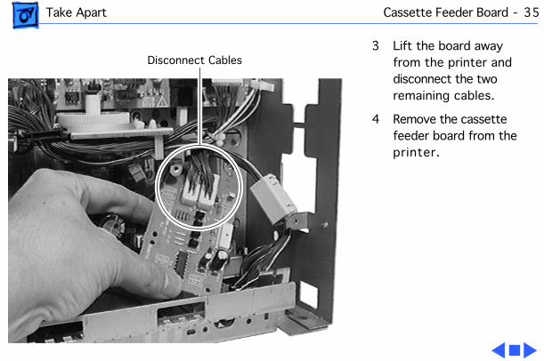
Take Apart Cassette Feeder Board - 35
3 Lift the board away from the printer and disconnect the two remaining cables.
4 Remove the cassette feeder board from the printer.
Disconnect Cables
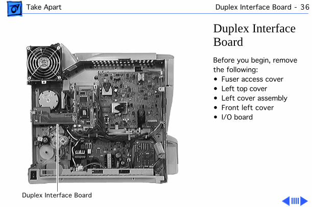
Take Apart Duplex Interface Board - 36
Duplex Interface Board
Before you begin, remove the following:• Fuser access cover• Left top cover• Left cover assembly• Front left cover• I/O board
Duplex Interface Board

Take Apart Duplex Interface Board - 37
1 Disconnect the cable on the rear face of the board.
2 Remove the two screws that secure the connector end of the board to the chassis frame.
Duplex Interface Board
Screws
Cable
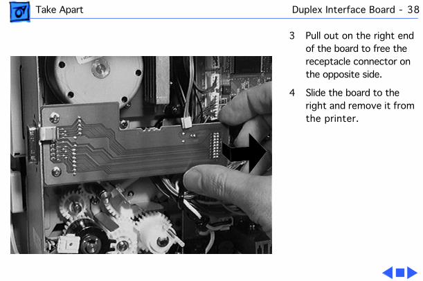
Take Apart Duplex Interface Board - 38
3 Pull out on the right end of the board to free the receptacle connector on the opposite side.
4 Slide the board to the right and remove it from the printer.

Take Apart DC Controller Board - 39
DC Controller Board
Before you begin, remove the following:• Fuser access cover• Left top cover• Left cover assembly• Front left cover• I/O board• Duplex interface board
DC Controller Board
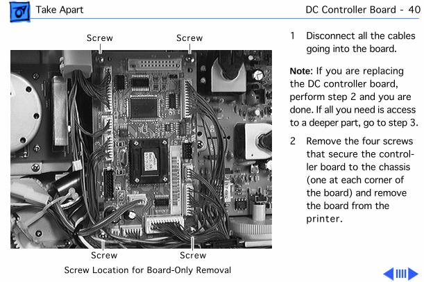
Take Apart DC Controller Board - 40
1 Disconnect all the cables going into the board.
Note
: If you are replacing the DC controller board, perform step 2 and you are done. If all you need is access to a deeper part, go to step 3.
2 Remove the four screws that secure the control-ler board to the chassis (one at each corner of the board) and remove the board from the printer.
ScrewScrew
Screw Screw
Screw Location for Board-Only Removal
Take Apart DC Controller Board - 41
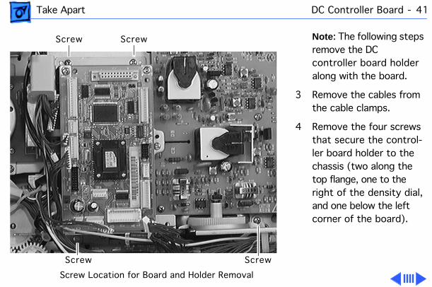
Note
: The following steps remove the DC controller board holder along with the board.
3 Remove the cables from the cable clamps.
4 Remove the four screws that secure the control-ler board holder to the chassis (two along the top flange, one to the right of the density dial, and one below the left corner of the board).
ScrewScrew
Screw Screw
Screw Location for Board and Holder Removal
Take Apart DC Controller Board - 42
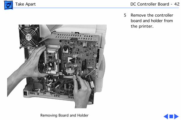
5 Remove the controller board and holder from the printer.
Removing Board and Holder
Take Apart Fan - 43
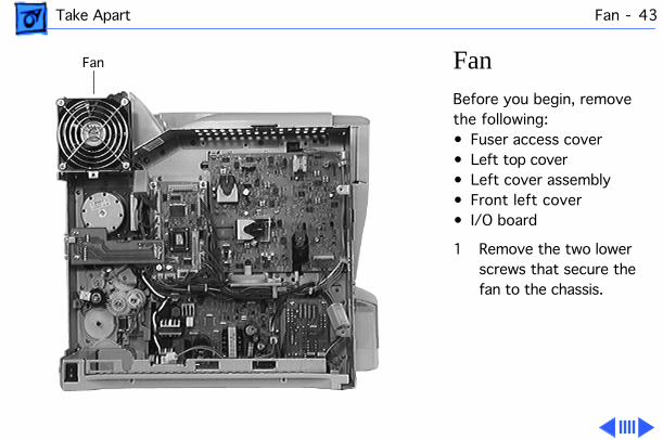
Fan
Before you begin, remove the following:• Fuser access cover• Left top cover• Left cover assembly• Front left cover• I/O board
1 Remove the two lower screws that secure the fan to the chassis.
Fan
Take Apart Fan - 44
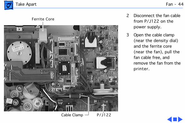
2 Disconnect the fan cable from P/J122 on the power supply.
3 Open the cable clamp (near the density dial) and the ferrite core (near the fan), pull the fan cable free, and remove the fan from the printer.
P/J122Cable Clamp
Ferrite Core
Take Apart Power Supply - 45
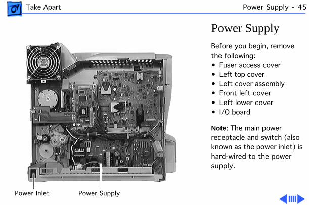
Power Supply
Before you begin, remove the following:• Fuser access cover• Left top cover• Left cover assembly• Front left cover• Left lower cover• I/O board
Note
: The main power receptacle and switch (also known as the power inlet) is hard-wired to the power supply.
Power Supply Power Inlet
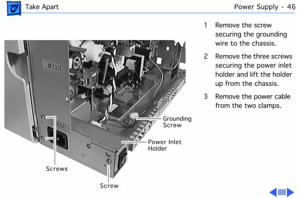
Take Apart Power Supply - 46
1 Remove the screw securing the grounding wire to the chassis.
2 Remove the three screws securing the power inlet holder and lift the holder up from the chassis.
3 Remove the power cable from the two clamps.
GroundingScrew
Screws
Screw
Power InletHolder
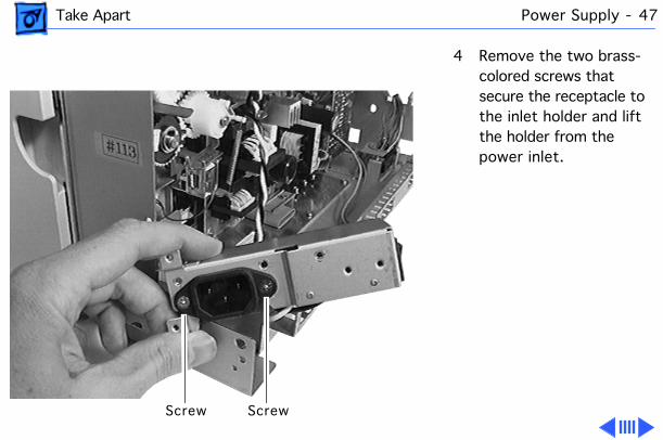
Take Apart Power Supply - 47
4 Remove the two brass-colored screws that secure the receptacle to the inlet holder and lift the holder from the power inlet.
ScrewScrew

Take Apart Power Supply - 48
5 Disconnect all the cables going into the power supply.
Replacement Note : Connector P127 is not used in this printer. The single wire orange cable goes into the P123 lead to the right of P127.
6 Remove the four screws securing the power supply to the chassis (two through the circuit board and two through the flange at the bottom).
Screw Screw
Screw ScrewPower Supply
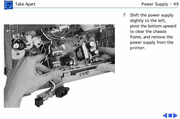
Take Apart Power Supply - 49
7 Shift the power supply slightly to the left, pivot the bottom upward to clear the chassis frame, and remove the power supply from the printer.
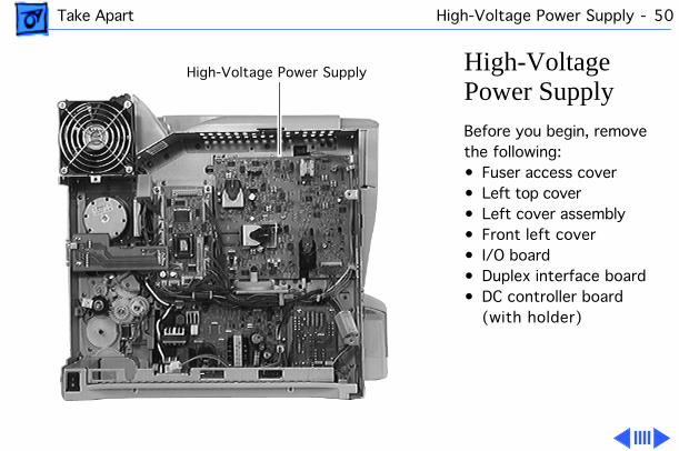
Take Apart High-Voltage Power Supply - 50
High-Voltage Power SupplyBefore you begin, remove the following:• Fuser access cover• Left top cover• Left cover assembly• Front left cover• I/O board• Duplex interface board• DC controller board
(with holder)
High-Voltage Power Supply
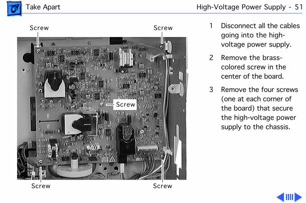
Take Apart High-Voltage Power Supply - 51
1 Disconnect all the cables going into the high-voltage power supply.
2 Remove the brass-colored screw in the center of the board.
3 Remove the four screws (one at each corner of the board) that secure the high-voltage power supply to the chassis.
Screw Screw
Screw Screw
Screw
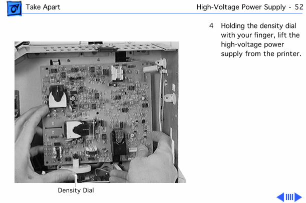
Take Apart High-Voltage Power Supply - 52
4 Holding the density dial with your finger, lift the high-voltage power supply from the printer.
Density Dial
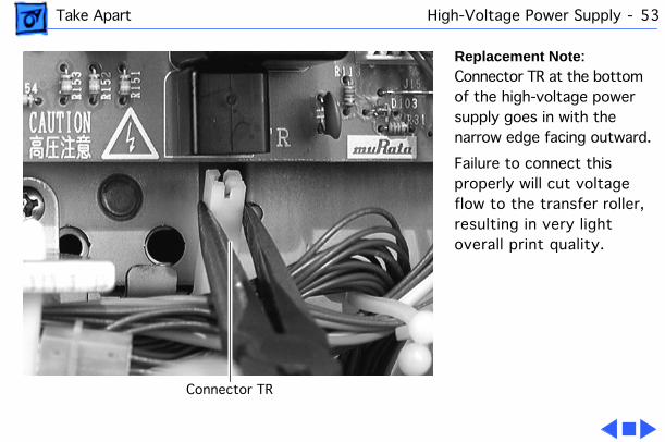
Take Apart High-Voltage Power Supply - 53
Replacement Note : Connector TR at the bottom of the high-voltage power supply goes in with the narrow edge facing outward.
Failure to connect this properly will cut voltage flow to the transfer roller, resulting in very light overall print quality.
Connector TR
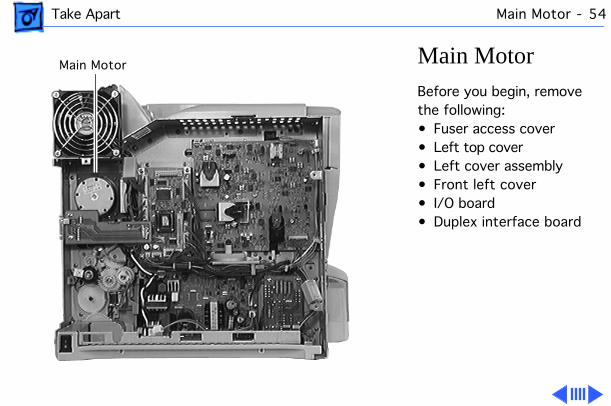
Take Apart Main Motor - 54
Main MotorBefore you begin, remove the following:• Fuser access cover• Left top cover• Left cover assembly• Front left cover• I/O board• Duplex interface board
Main Motor
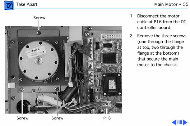
Take Apart Main Motor - 55
1 Disconnect the motor cable at P16 from the DC controller board.
2 Remove the three screws (one through the flange at top, two through the flange at the bottom) that secure the main motor to the chassis.
P16Screw Screw
Screw
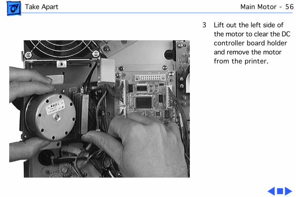
Take Apart Main Motor - 56
3 Lift out the left side of the motor to clear the DC controller board holder and remove the motor from the printer.
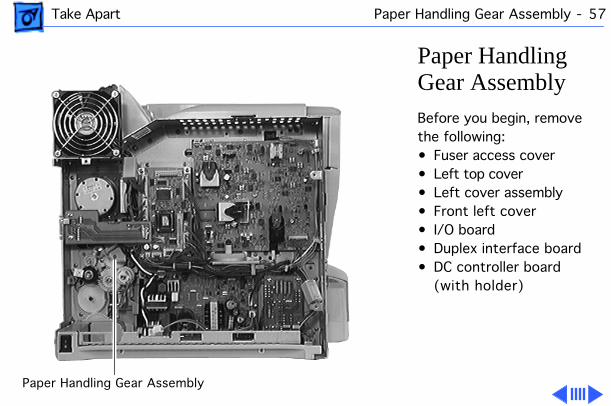
Take Apart Paper Handling Gear Assembly - 57
Paper Handling Gear AssemblyBefore you begin, remove the following:• Fuser access cover• Left top cover• Left cover assembly• Front left cover• I/O board• Duplex interface board• DC controller board
(with holder)
Paper Handling Gear Assembly
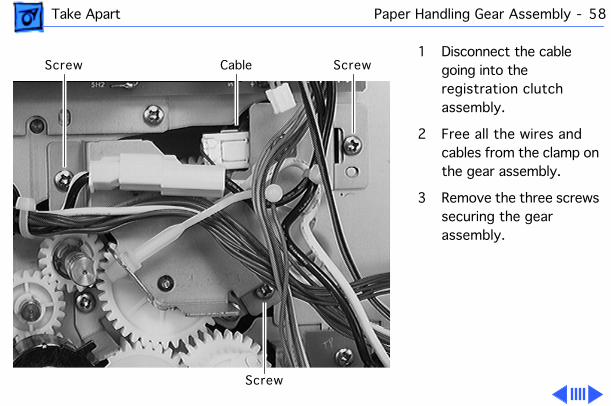
Take Apart Paper Handling Gear Assembly - 58
1 Disconnect the cable going into the registration clutch assembly.
2 Free all the wires and cables from the clamp on the gear assembly.
3 Remove the three screws securing the gear assembly.
Cable Screw
Screw
Screw
Take Apart Paper Handling Gear Assembly - 59
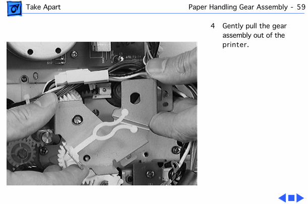
4 Gently pull the gear assembly out of the printer.
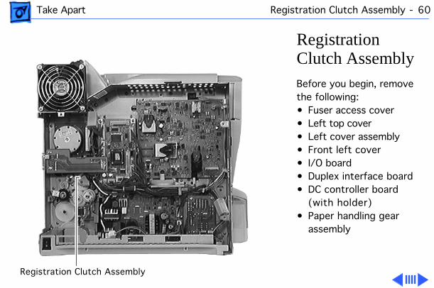
Take Apart Registration Clutch Assembly - 60
Registration Clutch AssemblyBefore you begin, remove the following:• Fuser access cover• Left top cover• Left cover assembly• Front left cover• I/O board• Duplex interface board• DC controller board
(with holder)• Paper handling gear
assembly
Registration Clutch Assembly
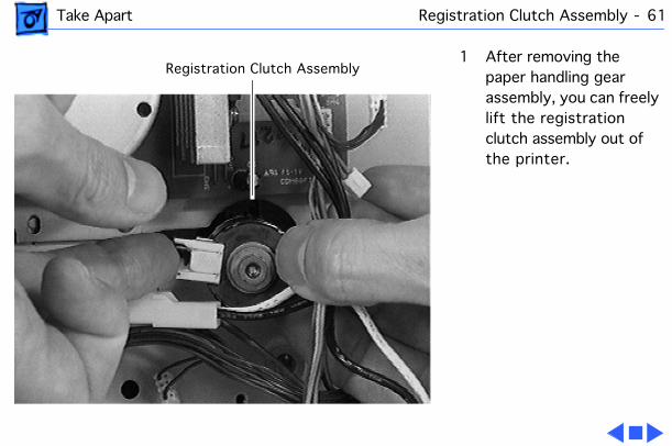
Take Apart Registration Clutch Assembly - 61
1 After removing the paper handling gear assembly, you can freely lift the registration clutch assembly out of the printer.
Registration Clutch Assembly

Take Apart Turn Clutch - 62
Turn ClutchBefore you begin, remove the following:• Fuser access cover• Left top cover• Left cover assembly• Front left cover• I/O board
Turn Clutch
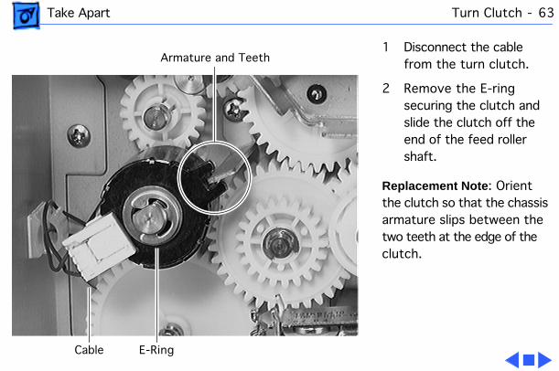
Take Apart Turn Clutch - 63
1 Disconnect the cable from the turn clutch.
2 Remove the E-ring securing the clutch and slide the clutch off the end of the feed roller shaft.
Replacement Note : Orient the clutch so that the chassis armature slips between the two teeth at the edge of the clutch.
Cable E-Ring
Armature and Teeth
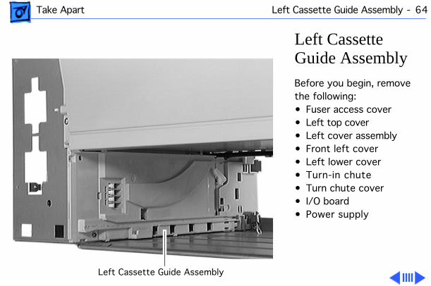
Take Apart Left Cassette Guide Assembly - 64
Left Cassette Guide AssemblyBefore you begin, remove the following:• Fuser access cover• Left top cover• Left cover assembly• Front left cover• Left lower cover• Turn-in chute• Turn chute cover• I/O board• Power supply
Left Cassette Guide Assembly
Take Apart Left Cassette Guide Assembly - 65
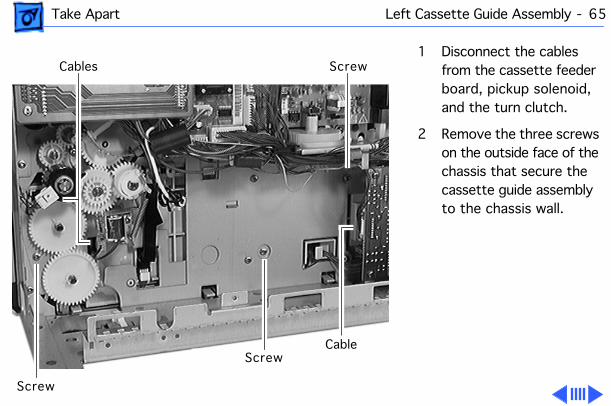
1 Disconnect the cables from the cassette feeder board, pickup solenoid, and the turn clutch.
2 Remove the three screws on the outside face of the chassis that secure the cassette guide assembly to the chassis wall.
Screw
Screw
ScrewCables
Cable
Take Apart Left Cassette Guide Assembly - 66
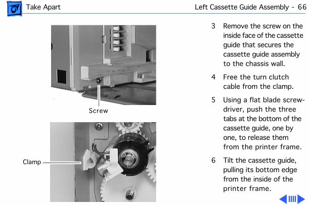
3 Remove the screw on the inside face of the cassette guide that secures the cassette guide assembly to the chassis wall.
4 Free the turn clutch cable from the clamp.
5 Using a flat blade screw-driver, push the three tabs at the bottom of the cassette guide, one by one, to release them from the printer frame.
6 Tilt the cassette guide, pulling its bottom edge from the inside of the printer frame.
Screw
Clamp
Take Apart Left Cassette Guide Assembly - 67
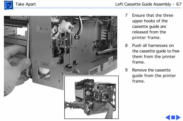
7 Ensure that the three upper hooks of the cassette guide are released from the printer frame.
8 Push all harnesses on the cassette guide to free them from the printer frame.
9 Remove the cassette guide from the printer frame.
Take Apart Cassette Paper-Present Sensor - 68
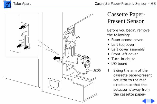
Cassette Paper-Present SensorBefore you begin, remove the following:• Fuser access cover• Left top cover• Left cover assembly• Front left cover• Turn-in chute• I/O board
1 Swing the arm of the cassette paper-present actuator to the rear direction so that the actuator is away from the cassette paper-
J205
Take Apart Cassette Paper-Present Sensor - 69
present sensor.
2 Open the turn chute cover.
3 Use a small flat blade screwdriver to release the hooks of the cassette paper-present sensor, located on the inside of the printer frame (work from the rear of the printer), from the left cassette guide assembly.
Note: Do not move the cassette paper-present sensor away, since it is connected with the feeder harness.
4 Disconnect P/J205 from the sensor.
5 Remove the sensor.
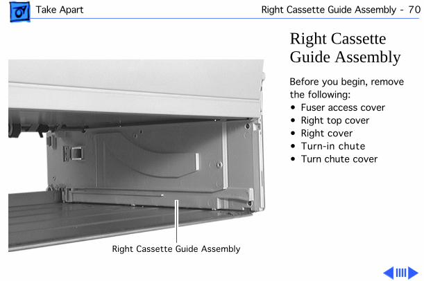
Take Apart Right Cassette Guide Assembly - 70
Right Cassette Guide AssemblyBefore you begin, remove the following:• Fuser access cover• Right top cover• Right cover• Turn-in chute• Turn chute cover
Right Cassette Guide Assembly
Take Apart Right Cassette Guide Assembly - 71
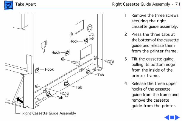
1 Remove the three screws securing the right cassette guide assembly.
2 Press the three tabs at the bottom of the cassette guide and release them from the printer frame.
3 Tilt the cassette guide, pulling its bottom edge from the inside of the printer frame.
4 Release the three upper hooks of the cassette guide from the frame and remove the cassette guide from the printer.
Tab
Hook
Hook
Hook
Right Cassette Guide Assembly
Tab
Tab
Take Apart Cassette Paper-Present Actuator - 72
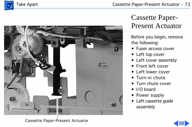
Cassette Paper-Present ActuatorBefore you begin, remove the following:• Fuser access cover• Left top cover• Left cover assembly• Front left cover• Left lower cover• Turn-in chute• Turn chute cover• I/O board• Power supply• Left cassette guide
assembly
Cassette Paper-Present Actuator
Take Apart Cassette Paper-Present Actuator - 73
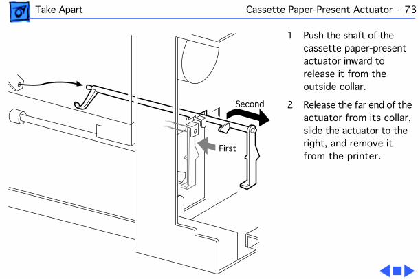
1 Push the shaft of the cassette paper-present actuator inward to release it from the outside collar.
2 Release the far end of the actuator from its collar, slide the actuator to the right, and remove it from the printer.
First
Second
Take Apart Cassette Pickup Roller(s) - 74
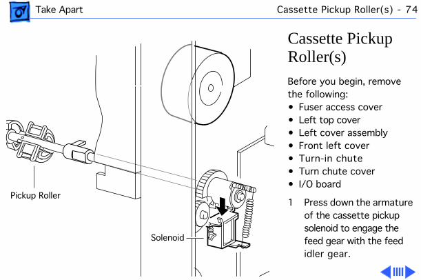
Cassette Pickup Roller(s)Before you begin, remove the following:• Fuser access cover• Left top cover• Left cover assembly• Front left cover• Turn-in chute• Turn chute cover• I/O board
1 Press down the armature of the cassette pickup solenoid to engage the feed gear with the feed idler gear.
Solenoid
Pickup Roller
Take Apart Cassette Pickup Roller(s) - 75
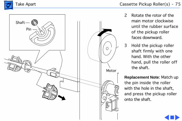
2 Rotate the rotor of the main motor clockwise until the rubber surface of the pickup roller faces downward.
3 Hold the pickup roller shaft firmly with one hand. With the other hand, pull the roller off the shaft.
Replacement Note : Match up the pin inside the roller with the hole in the shaft, and press the pickup roller onto the shaft.
Pin
Shaft
Motor

Take Apart Cassette Pickup Solenoid - 76
Cassette Pickup SolenoidBefore you begin, remove the following:• Fuser access cover• Left top cover• Left cover assembly• Front left cover• I/O board
Cassette Pickup Solenoid
Take Apart Cassette Pickup Solenoid - 77
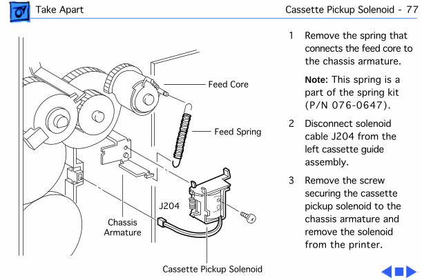
1 Remove the spring that connects the feed core to the chassis armature.
Note : This spring is a part of the spring kit (P/N 076-0647).
2 Disconnect solenoid cable J204 from the left cassette guide assembly.
3 Remove the screw securing the cassette pickup solenoid to the chassis armature and remove the solenoid from the printer.
J204
Feed Spring
Cassette Pickup Solenoid
ChassisArmature
Feed Core
Take Apart Lower Feed Roller - 78
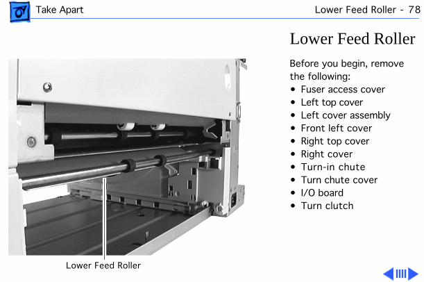
Lower Feed RollerBefore you begin, remove the following:• Fuser access cover• Left top cover• Left cover assembly• Front left cover• Right top cover• Right cover• Turn-in chute• Turn chute cover• I/O board• Turn clutch
Lower Feed Roller
Take Apart Lower Feed Roller - 79
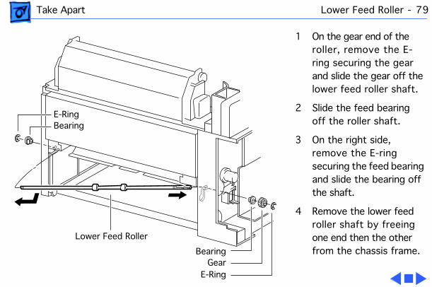
1 On the gear end of the roller, remove the E-ring securing the gear and slide the gear off the lower feed roller shaft.
2 Slide the feed bearing off the roller shaft.
3 On the right side, remove the E-ring securing the feed bearing and slide the bearing off the shaft.
4 Remove the lower feed roller shaft by freeing one end then the other from the chassis frame.
GearE-Ring
Bearing
BearingE-Ring
Lower Feed Roller
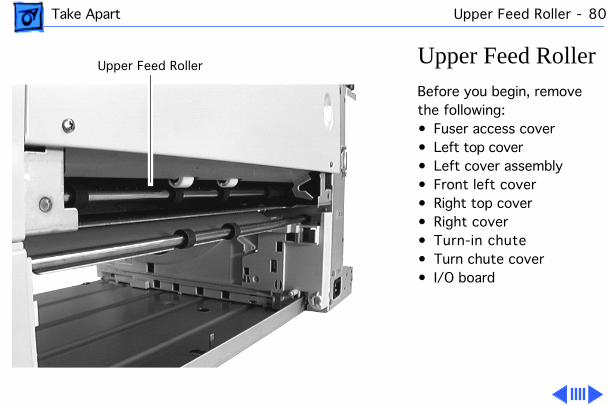
Take Apart Upper Feed Roller - 80
Upper Feed RollerBefore you begin, remove the following:• Fuser access cover• Left top cover• Left cover assembly• Front left cover• Right top cover• Right cover• Turn-in chute• Turn chute cover• I/O board
Upper Feed Roller
Take Apart Upper Feed Roller - 81
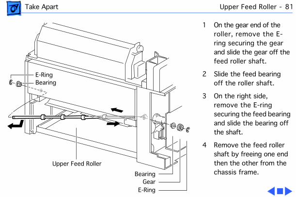
1 On the gear end of the roller, remove the E-ring securing the gear and slide the gear off the feed roller shaft.
2 Slide the feed bearing off the roller shaft.
3 On the right side, remove the E-ring securing the feed bearing and slide the bearing off the shaft.
4 Remove the feed roller shaft by freeing one end then the other from the chassis frame.
GearE-Ring
Bearing
BearingE-Ring
Upper Feed Roller
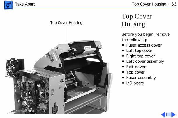
Take Apart Top Cover Housing - 82
Top Cover HousingBefore you begin, remove the following:• Fuser access cover• Left top cover• Right top cover• Left cover assembly• Exit cover• Top cover• Fuser assembly• I/O board
Top Cover Housing
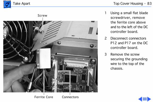
Take Apart Top Cover Housing - 83
1 Using a small flat blade screwdriver, remove the ferrite core above and to the left of the DC controller board.
2 Disconnect connectors P12 and P17 on the DC controller board.
3 Remove the screw securing the grounding wire to the top of the chassis.
Ferrite Core
Screw
Connectors
Take Apart Top Cover Housing - 84
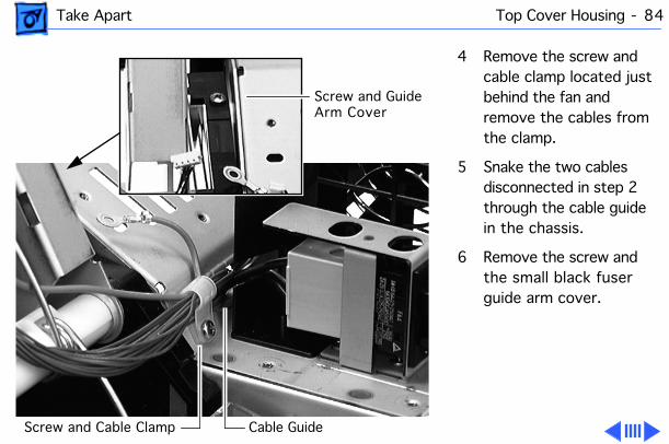
4 Remove the screw and cable clamp located just behind the fan and remove the cables from the clamp.
5 Snake the two cables disconnected in step 2 through the cable guide in the chassis.
6 Remove the screw and the small black fuser guide arm cover.
Screw and Cable Clamp Cable Guide
Screw and GuideArm Cover
Take Apart Top Cover Housing - 85
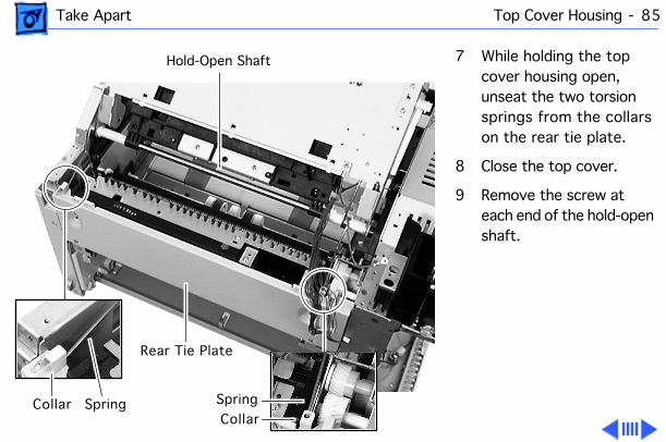
7 While holding the top cover housing open, unseat the two torsion springs from the collars on the rear tie plate.
8 Close the top cover.
9 Remove the screw at each end of the hold-open shaft.
Rear Tie Plate
Hold-Open Shaft
Collar SpringCollar
Spring
Take Apart Top Cover Housing - 86
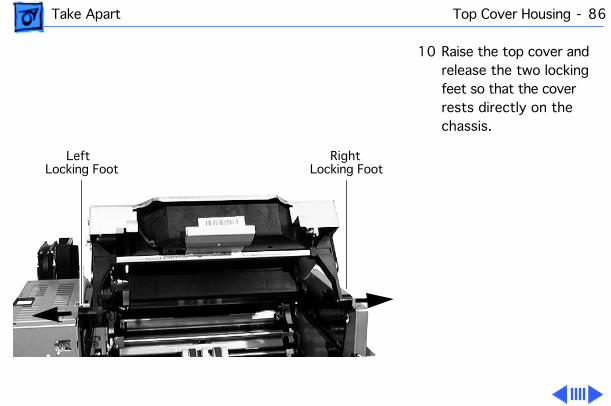
10 Raise the top cover and release the two locking feet so that the cover rests directly on the chassis.
Right Locking Foot
Left Locking Foot
Take Apart Top Cover Housing - 87
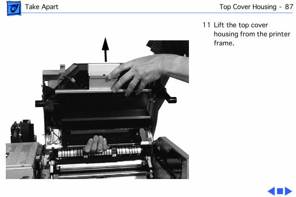
11 Lift the top cover housing from the printer frame.
Take Apart Laser/Scanner Assembly - 88
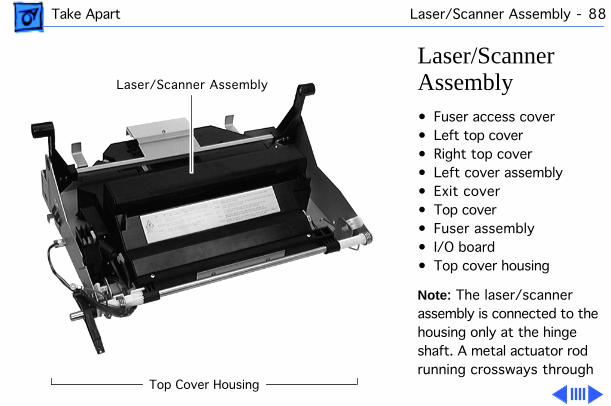
Laser/Scanner Assembly• Fuser access cover• Left top cover• Right top cover• Left cover assembly• Exit cover• Top cover• Fuser assembly• I/O board• Top cover housing
Note : The laser/scanner assembly is connected to the housing only at the hinge shaft. A metal actuator rod running crossways through
Laser/Scanner Assembly
Top Cover Housing
Take Apart Laser/Scanner Assembly - 89
the housing is also screwed to the laser/scanner assembly. Steps 1-5 below remove the rod from the housing. The remaining steps remove the laser/scanner assembly from the hinge shaft.
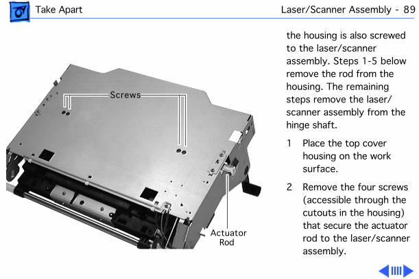
1 Place the top cover housing on the work surface.
2 Remove the four screws (accessible through the cutouts in the housing) that secure the actuator rod to the laser/scanner assembly.
Screws
ActuatorRod
Take Apart Laser/Scanner Assembly - 90
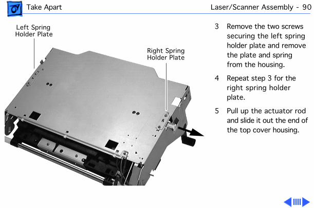
3 Remove the two screws securing the left spring holder plate and remove the plate and spring from the housing.
4 Repeat step 3 for the right spring holder plate.
5 Pull up the actuator rod and slide it out the end of the top cover housing.
Right SpringHolder Plate
Left SpringHolder Plate
Take Apart Laser/Scanner Assembly - 91
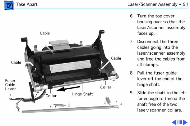
6 Turn the top cover housing over so that the laser/scanner assembly faces up.
7 Disconnect the three cables going into the laser/scanner assembly and free the cables from all clamps.
8 Pull the fuser guide lever off the end of the hinge shaft.
9 Slide the shaft to the left far enough to thread the shaft free of the two laser/scanner collars.
Fuser
Hinge Shaft
GuideLever
Cable
CableCable
Collar
Collar
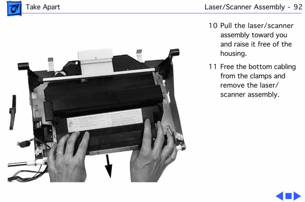
Take Apart Laser/Scanner Assembly - 92
10 Pull the laser/scanner assembly toward you and raise it free of the housing.
11 Free the bottom cabling from the clamps and remove the laser/scanner assembly.
Take Apart Cartridge Sensor Assembly - 93
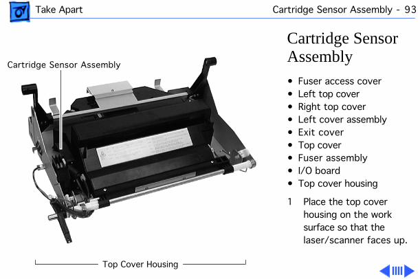
Cartridge Sensor Assembly• Fuser access cover• Left top cover• Right top cover• Left cover assembly• Exit cover• Top cover• Fuser assembly• I/O board• Top cover housing
1 Place the top cover housing on the work surface so that the laser/scanner faces up.
Cartridge Sensor Assembly
Top Cover Housing
Take Apart Cartridge Sensor Assembly - 94
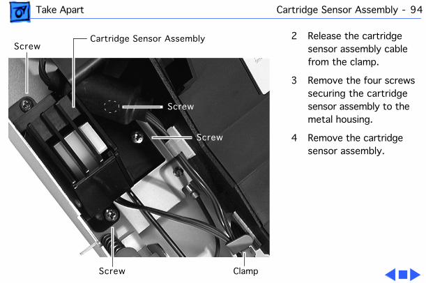
2 Release the cartridge sensor assembly cable from the clamp.
3 Remove the four screws securing the cartridge sensor assembly to the metal housing.
4 Remove the cartridge sensor assembly.
Screw
Screw
Screw
Screw
Clamp
Cartridge Sensor Assembly
Take Apart Manual Feed Sensor Assembly - 95
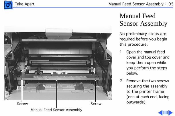
Manual Feed Sensor AssemblyNo preliminary steps are required before you begin this procedure.
1 Open the manual feed cover and top cover and keep them open while you perform the steps below.
2 Remove the two screws securing the assembly to the printer frame (one at each end, facing outwards).Screw Screw
Manual Feed Sensor Assembly
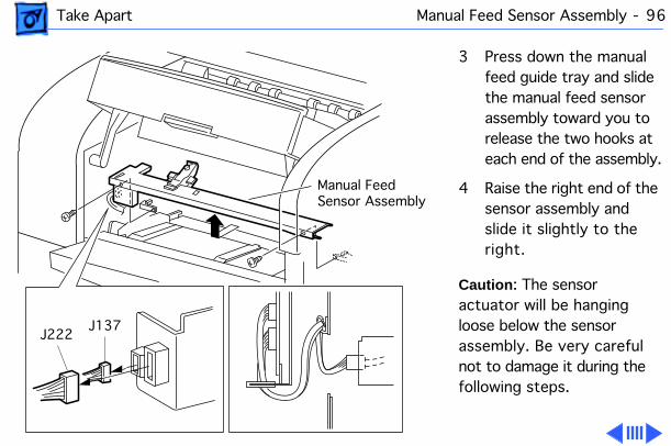
Take Apart Manual Feed Sensor Assembly - 96
3 Press down the manual feed guide tray and slide the manual feed sensor assembly toward you to release the two hooks at each end of the assembly.
4 Raise the right end of the sensor assembly and slide it slightly to the right.
Caution : The sensor actuator will be hanging loose below the sensor assembly. Be very careful not to damage it during the following steps.
J222J137
Manual FeedSensor Assembly
Take Apart Manual Feed Sensor Assembly - 97
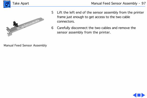
5 Lift the left end of the sensor assembly from the printer frame just enough to get access to the two cable connectors.
6 Carefully disconnect the two cables and remove the sensor assembly from the printer.
Manual Feed Sensor Assembly
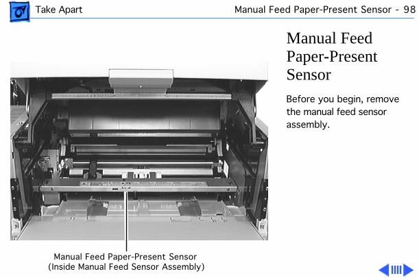
Take Apart Manual Feed Paper-Present Sensor - 98
Manual Feed Paper-Present SensorBefore you begin, remove the manual feed sensor assembly.
Manual Feed Paper-Present Sensor(Inside Manual Feed Sensor Assembly)
Take Apart Manual Feed Paper-Present Sensor - 99
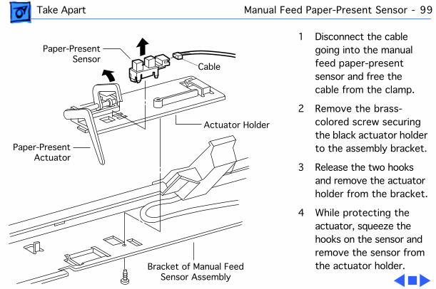
1 Disconnect the cable going into the manual feed paper-present sensor and free the cable from the clamp.
2 Remove the brass-colored screw securing the black actuator holder to the assembly bracket.
3 Release the two hooks and remove the actuator holder from the bracket.
4 While protecting the actuator, squeeze the hooks on the sensor and remove the sensor from the actuator holder.
Cable
Bracket of Manual Feed Sensor Assembly
Actuator Holder
Paper-PresentActuator
Paper-PresentSensor
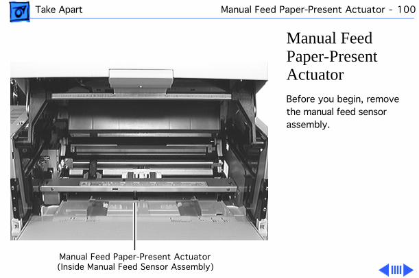
Take Apart Manual Feed Paper-Present Actuator - 100
Manual Feed Paper-Present ActuatorBefore you begin, remove the manual feed sensor assembly.
Manual Feed Paper-Present Actuator(Inside Manual Feed Sensor Assembly)
Take Apart Manual Feed Paper-Present Actuator - 101
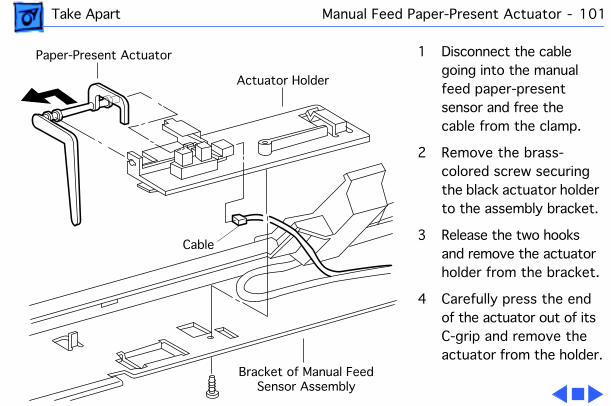
1 Disconnect the cable going into the manual feed paper-present sensor and free the cable from the clamp.
2 Remove the brass-colored screw securing the black actuator holder to the assembly bracket.
3 Release the two hooks and remove the actuator holder from the bracket.
4 Carefully press the end of the actuator out of its C-grip and remove the actuator from the holder.
Cable
Bracket of Manual Feed Sensor Assembly
Paper-Present Actuator
Actuator Holder
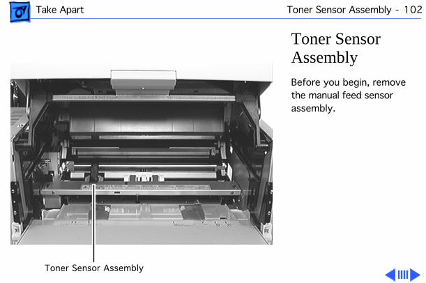
Take Apart Toner Sensor Assembly - 102
Toner Sensor AssemblyBefore you begin, remove the manual feed sensor assembly.
Toner Sensor Assembly
Take Apart Toner Sensor Assembly - 103
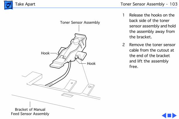
1 Release the hooks on the back side of the toner sensor assembly and hold the assembly away from the bracket.
2 Remove the toner sensor cable from the cutout at the end of the bracket and lift the assembly free.
Hook
Hook
Toner Sensor Assembly
Bracket of ManualFeed Sensor Assembly
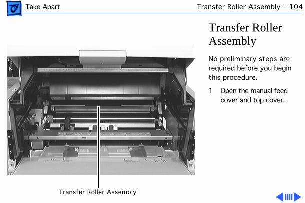
Take Apart Transfer Roller Assembly - 104
Transfer Roller AssemblyNo preliminary steps are required before you begin this procedure.
1 Open the manual feed cover and top cover.
Transfer Roller Assembly
Take Apart Transfer Roller Assembly - 105
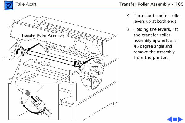
2 Turn the transfer roller levers up at both ends.
3 Holding the levers, lift the transfer roller assembly upwards at a 45 degree angle and remove the assembly from the printer.Lever
Transfer Roller Assembly
Lever
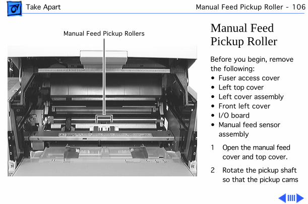
Take Apart Manual Feed Pickup Roller - 106
Manual Feed Pickup RollerBefore you begin, remove the following:• Fuser access cover• Left top cover• Left cover assembly• Front left cover• I/O board• Manual feed sensor
assembly
1 Open the manual feed cover and top cover.
2 Rotate the pickup shaft so that the pickup cams
Manual Feed Pickup Rollers
Take Apart Manual Feed Pickup Roller - 107
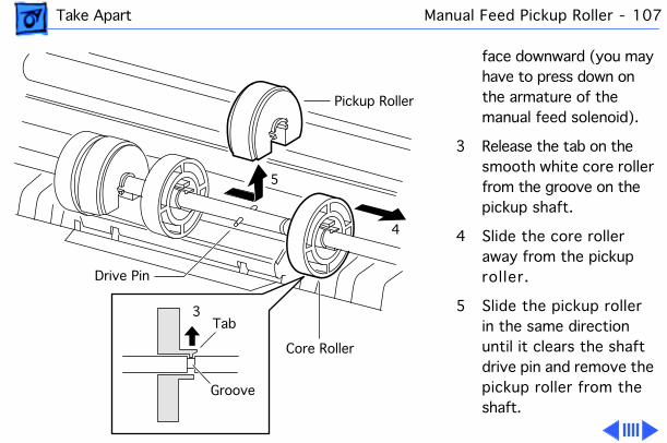
face downward (you may have to press down on the armature of the manual feed solenoid).
3 Release the tab on the smooth white core roller from the groove on the pickup shaft.
4 Slide the core roller away from the pickup roller.
5 Slide the pickup roller in the same direction until it clears the shaft drive pin and remove the pickup roller from the shaft.
Core Roller
4
3
5
Pickup Roller
Drive Pin
Tab
Groove
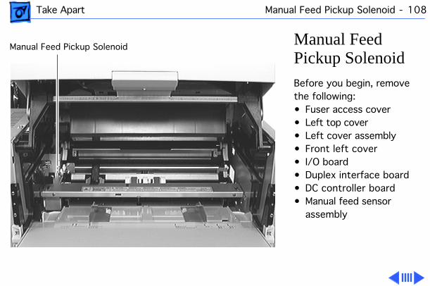
Take Apart Manual Feed Pickup Solenoid - 108
Manual Feed Pickup SolenoidBefore you begin, remove the following:• Fuser access cover• Left top cover• Left cover assembly• Front left cover• I/O board• Duplex interface board• DC controller board• Manual feed sensor
assembly
Manual Feed Pickup Solenoid
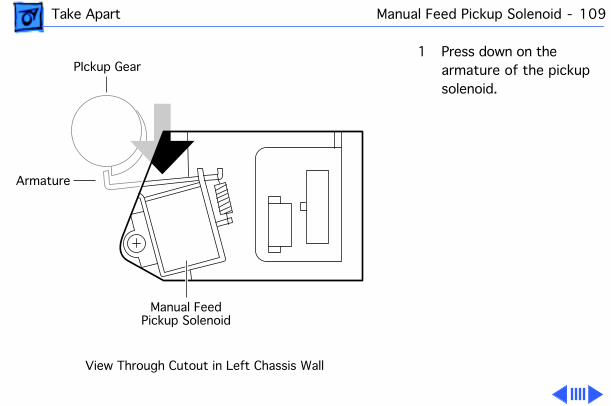
Take Apart Manual Feed Pickup Solenoid - 109
1 Press down on the armature of the pickup solenoid.
View Through Cutout in Left Chassis Wall
Manual Feed Pickup Solenoid
Armature
PIckup Gear
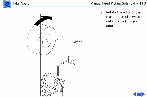
Take Apart Manual Feed Pickup Solenoid - 110
2 Rotate the rotor of the main motor clockwise until the pickup gear stops.
Motor
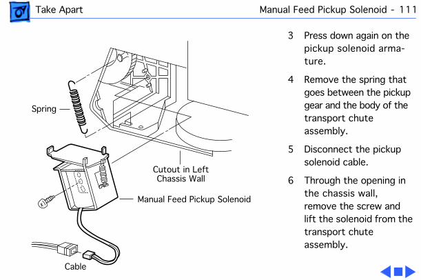
Take Apart Manual Feed Pickup Solenoid - 111
3 Press down again on the pickup solenoid arma-ture.
4 Remove the spring that goes between the pickup gear and the body of the transport chute assembly.
5 Disconnect the pickup solenoid cable.
6 Through the opening in the chassis wall, remove the screw and lift the solenoid from the transport chute assembly.
Manual Feed Pickup Solenoid
Spring
Cutout in LeftChassis Wall
Cable
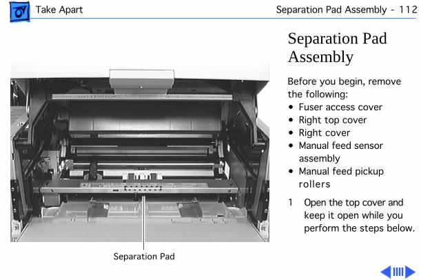
Take Apart Separation Pad Assembly - 112
Separation Pad AssemblyBefore you begin, remove the following:• Fuser access cover• Right top cover• Right cover• Manual feed sensor
assembly• Manual feed pickup
rollers
1 Open the top cover and keep it open while you perform the steps below.
Separation Pad
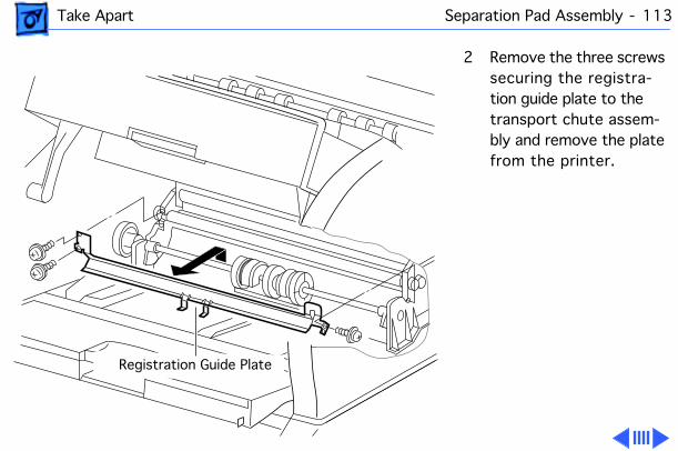
Take Apart Separation Pad Assembly - 113
2 Remove the three screws securing the registra-tion guide plate to the transport chute assem-bly and remove the plate from the printer.
Registration Guide Plate
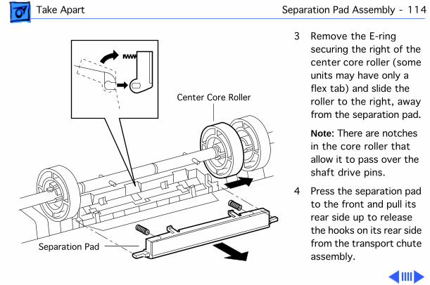
Take Apart Separation Pad Assembly - 114
3 Remove the E-ring securing the right of the center core roller (some units may have only a flex tab) and slide the roller to the right, away from the separation pad.
Note : There are notches in the core roller that allow it to pass over the shaft drive pins.
4 Press the separation pad to the front and pull its rear side up to release the hooks on its rear side from the transport chute assembly.
Center Core Roller
Separation Pad
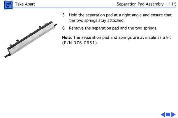
Take Apart Separation Pad Assembly - 115
5 Hold the separation pad at a right angle and ensure that the two springs stay attached.
6 Remove the separation pad and the two springs.
Note : The separation pad and springs are available as a kit (P/N 076-0651).
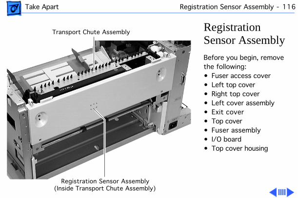
Take Apart Registration Sensor Assembly - 116
Registration Sensor AssemblyBefore you begin, remove the following:• Fuser access cover• Left top cover• Right top cover• Left cover assembly• Exit cover• Top cover• Fuser assembly• I/O board• Top cover housing
Transport Chute Assembly
Registration Sensor Assembly(Inside Transport Chute Assembly)
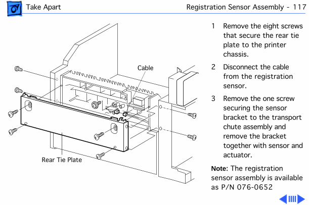
Take Apart Registration Sensor Assembly - 117
1 Remove the eight screws that secure the rear tie plate to the printer chassis.
2 Disconnect the cable from the registration sensor.
3 Remove the one screw securing the sensor bracket to the transport chute assembly and remove the bracket together with sensor and actuator.
Note : The registration sensor assembly is available as P/N 076-0652
Cable
Rear Tie Plate
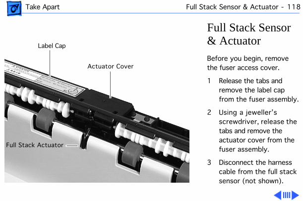
Take Apart Full Stack Sensor & Actuator - 118
Full Stack Sensor & ActuatorBefore you begin, remove the fuser access cover.
1 Release the tabs and remove the label cap from the fuser assembly.
2 Using a jeweller’s screwdriver, release the tabs and remove the actuator cover from the fuser assembly.
3 Disconnect the harness cable from the full stack sensor (not shown).
Actuator Cover
Label Cap
Full Stack Actuator
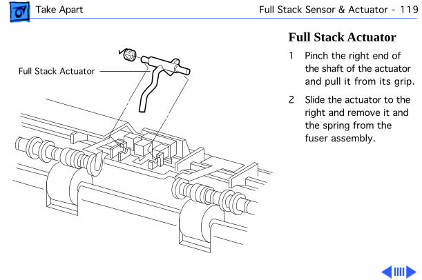
Take Apart Full Stack Sensor & Actuator - 119
Full Stack Actuator1 Pinch the right end of
the shaft of the actuator and pull it from its grip.
2 Slide the actuator to the right and remove it and the spring from the fuser assembly.
Full Stack Actuator
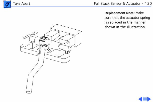
Take Apart Full Stack Sensor & Actuator - 120
Replacement Note : Make sure that the actuator spring is replaced in the manner shown in the illustration.
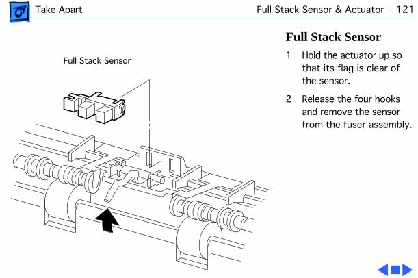
Take Apart Full Stack Sensor & Actuator - 121
Full Stack Sensor1 Hold the actuator up so
that its flag is clear of the sensor.
2 Release the four hooks and remove the sensor from the fuser assembly.
Full Stack Sensor
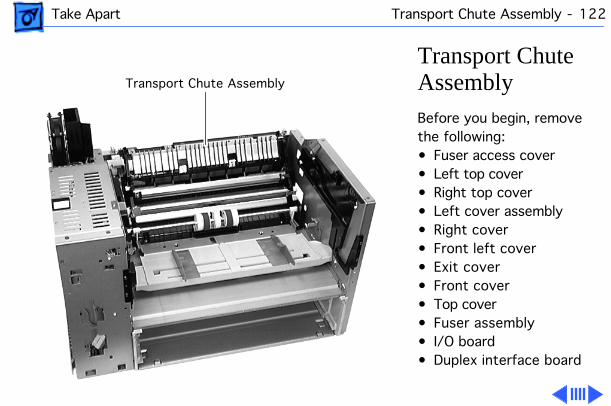
Take Apart Transport Chute Assembly - 122
Transport Chute AssemblyBefore you begin, remove the following:• Fuser access cover• Left top cover• Right top cover• Left cover assembly• Right cover• Front left cover• Exit cover• Front cover• Top cover• Fuser assembly• I/O board• Duplex interface board
Transport Chute Assembly
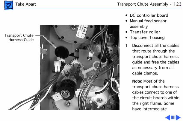
Take Apart Transport Chute Assembly - 123
• DC controller board• Manual feed sensor
assembly• Transfer roller• Top cover housing
1 Disconnect all the cables that route through the transport chute harness guide and free the cables as necessary from all cable clamps.
Note : Most of the transport chute harness cables connect to one of the circuit boards within the right frame. Some have intermediate
Transport ChuteHarness Guide
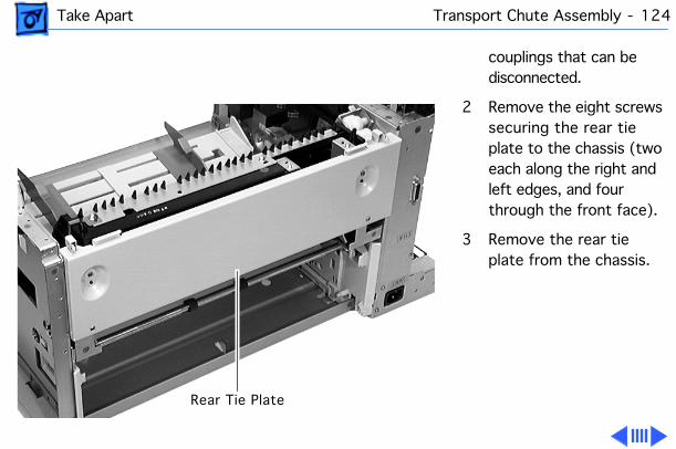
Take Apart Transport Chute Assembly - 124
couplings that can be disconnected.
2 Remove the eight screws securing the rear tie plate to the chassis (two each along the right and left edges, and four through the front face).
3 Remove the rear tie plate from the chassis.
Rear Tie Plate
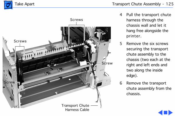
Take Apart Transport Chute Assembly - 125
4 Pull the transport chute harness through the chassis wall and let it hang free alongside the printer.
5 Remove the six screws securing the transport chute assembly to the chassis (two each at the right and left ends and two along the inside edge).
6 Remove the transport chute assembly from the chassis.
Transport ChuteHarness Cable
Screws
Screw
Screw
Screws
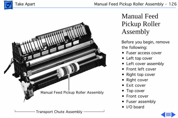
Take Apart Manual Feed Pickup Roller Assembly - 126
Manual Feed Pickup Roller AssemblyBefore you begin, remove the following:• Fuser access cover• Left top cover• Left cover assembly• Front left cover• Right top cover• Right cover• Exit cover• Top cover• Front cover• Fuser assembly• I/O board
Transport Chute Assembly
Manual Feed Pickup Roller Assembly
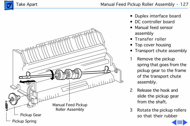
Take Apart Manual Feed Pickup Roller Assembly - 127
• Duplex interface board• DC controller board• Manual feed sensor
assembly• Transfer roller• Top cover housing• Transport chute assembly
1 Remove the pickup spring that goes from the pickup gear to the frame of the transport chute assembly.
2 Release the hook and slide the pickup gear from the shaft.
3 Rotate the pickup rollers so that their rubber
Pickup Spring
Pickup Gear
Manual Feed PickupRoller Assembly
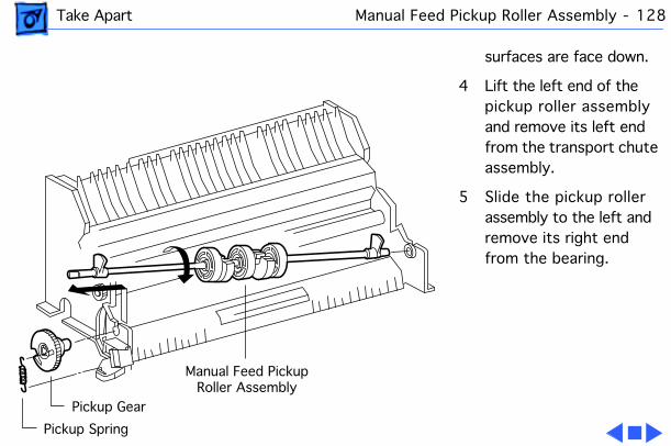
Take Apart Manual Feed Pickup Roller Assembly - 128
surfaces are face down.
4 Lift the left end of the pickup roller assembly and remove its left end from the transport chute assembly.
5 Slide the pickup roller assembly to the left and remove its right end from the bearing.
Pickup Spring
Pickup Gear
Manual Feed PickupRoller Assembly
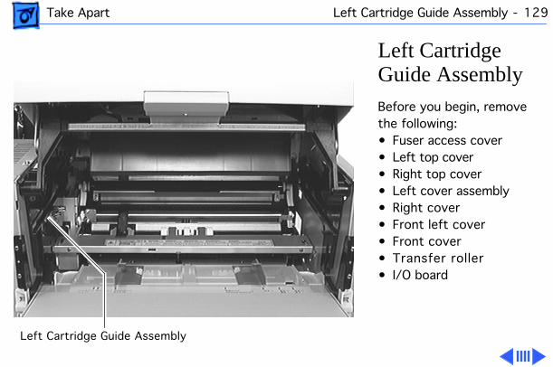
Take Apart Left Cartridge Guide Assembly - 129
Left Cartridge Guide AssemblyBefore you begin, remove the following:• Fuser access cover• Left top cover• Right top cover• Left cover assembly• Right cover• Front left cover• Front cover• Transfer roller• I/O board
Left Cartridge Guide Assembly
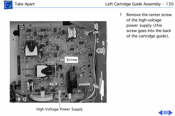
Take Apart Left Cartridge Guide Assembly - 130
1 Remove the center screw of the high-voltage power supply (this screw goes into the back of the cartridge guide).
Screw
High-Voltage Power Supply
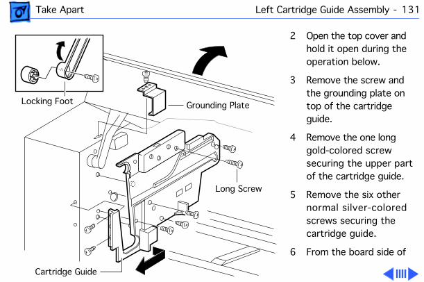
Take Apart Left Cartridge Guide Assembly - 131
2 Open the top cover and hold it open during the operation below.
3 Remove the screw and the grounding plate on top of the cartridge guide.
4 Remove the one long gold-colored screw securing the upper part of the cartridge guide.
5 Remove the six other normal silver-colored screws securing the cartridge guide.
6 From the board side of
Grounding PlateLocking Foot
Cartridge Guide
Long Screw
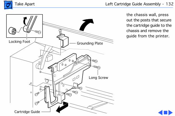
Take Apart Left Cartridge Guide Assembly - 132
the chassis wall, press out the posts that secure the cartridge guide to the chassis and remove the guide from the printer.
Grounding PlateLocking Foot
Cartridge Guide
Long Screw
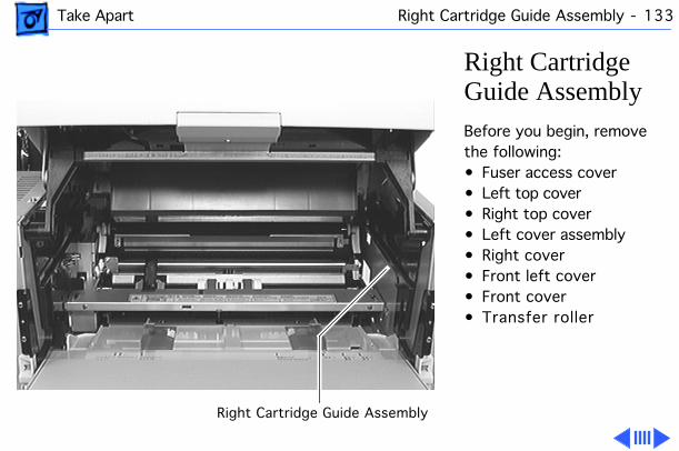
Take Apart Right Cartridge Guide Assembly - 133
Right Cartridge Guide AssemblyBefore you begin, remove the following:• Fuser access cover• Left top cover• Right top cover• Left cover assembly• Right cover• Front left cover• Front cover• Transfer roller
Right Cartridge Guide Assembly
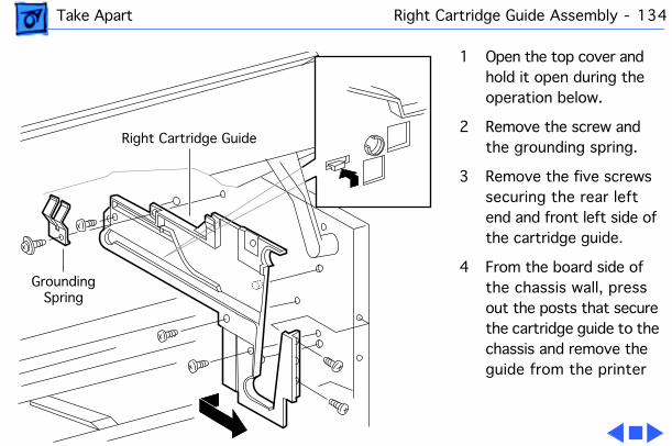
Take Apart Right Cartridge Guide Assembly - 134
1 Open the top cover and hold it open during the operation below.
2 Remove the screw and the grounding spring.
3 Remove the five screws securing the rear left end and front left side of the cartridge guide.
4 From the board side of the chassis wall, press out the posts that secure the cartridge guide to the chassis and remove the guide from the printer
GroundingSpring
Right Cartridge Guide
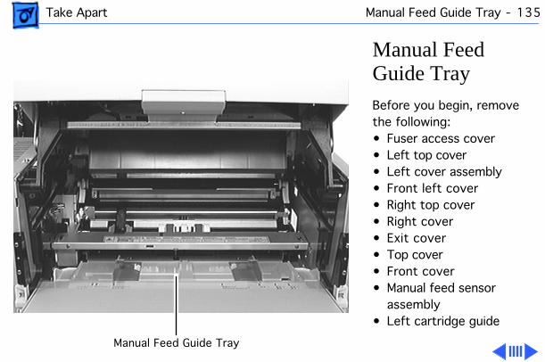
Take Apart Manual Feed Guide Tray - 135
Manual Feed Guide TrayBefore you begin, remove the following:• Fuser access cover• Left top cover• Left cover assembly• Front left cover• Right top cover• Right cover• Exit cover• Top cover• Front cover• Manual feed sensor
assembly• Left cartridge guide
Manual Feed Guide Tray
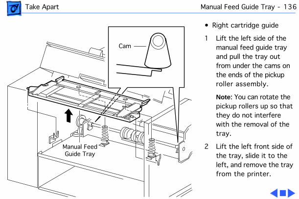
Take Apart Manual Feed Guide Tray - 136
• Right cartridge guide
1 Lift the left side of the manual feed guide tray and pull the tray out from under the cams on the ends of the pickup roller assembly.
Note : You can rotate the pickup rollers up so that they do not interfere with the removal of the tray.
2 Lift the left front side of the tray, slide it to the left, and remove the tray from the printer.
Manual FeedGuide Tray
Cam
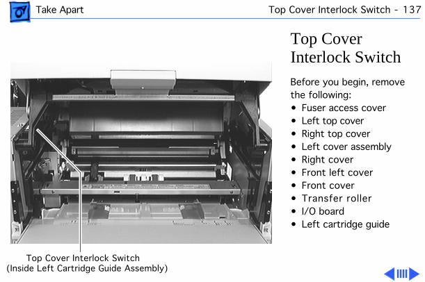
Take Apart Top Cover Interlock Switch - 137
Top Cover Interlock SwitchBefore you begin, remove the following:• Fuser access cover• Left top cover• Right top cover• Left cover assembly• Right cover• Front left cover• Front cover• Transfer roller• I/O board• Left cartridge guide
Top Cover Interlock Switch(Inside Left Cartridge Guide Assembly)
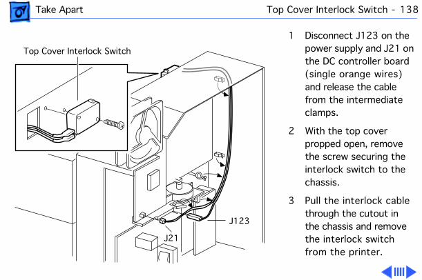
Take Apart Top Cover Interlock Switch - 138
1 Disconnect J123 on the power supply and J21 on the DC controller board (single orange wires) and release the cable from the intermediate clamps.
2 With the top cover propped open, remove the screw securing the interlock switch to the chassis.
3 Pull the interlock cable through the cutout in the chassis and remove the interlock switch from the printer.
J21
J123
Top Cover Interlock Switch
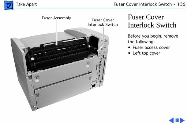
Take Apart Fuser Cover Interlock Switch - 139
Fuser Cover Interlock SwitchBefore you begin, remove the following:• Fuser access cover• Left top cover
Fuser Assembly Fuser CoverInterlock Switch
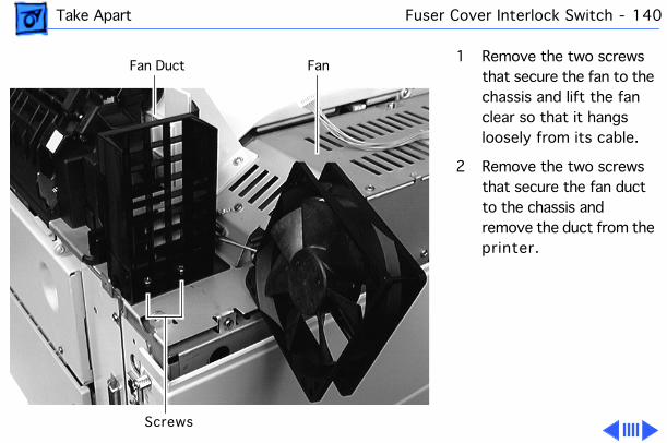
Take Apart Fuser Cover Interlock Switch - 140
1 Remove the two screws that secure the fan to the chassis and lift the fan clear so that it hangs loosely from its cable.
2 Remove the two screws that secure the fan duct to the chassis and remove the duct from the printer.
Fan
Screws
Fan Duct
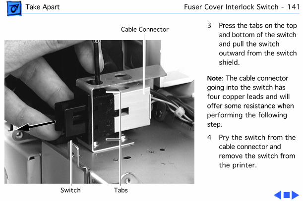
Take Apart Fuser Cover Interlock Switch - 141
3 Press the tabs on the top and bottom of the switch and pull the switch outward from the switch shield.
Note : The cable connector going into the switch has four copper leads and will offer some resistance when performing the following step.
4 Pry the switch from the cable connector and remove the switch from the printer.
Switch
Cable Connector
Tabs
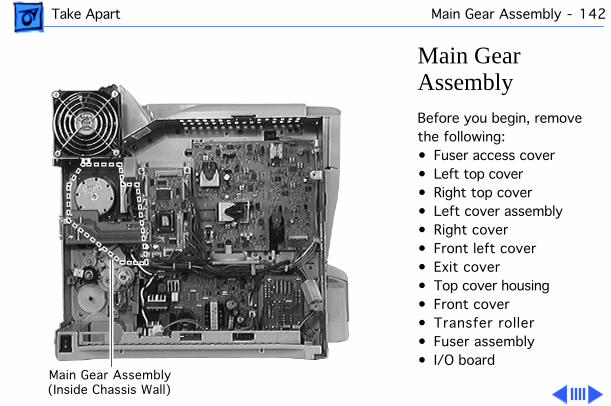
Take Apart Main Gear Assembly - 142
Main Gear AssemblyBefore you begin, remove the following:• Fuser access cover• Left top cover• Right top cover• Left cover assembly• Right cover• Front left cover• Exit cover• Top cover housing• Front cover• Transfer roller• Fuser assembly• I/O board
Main Gear Assembly(Inside Chassis Wall)
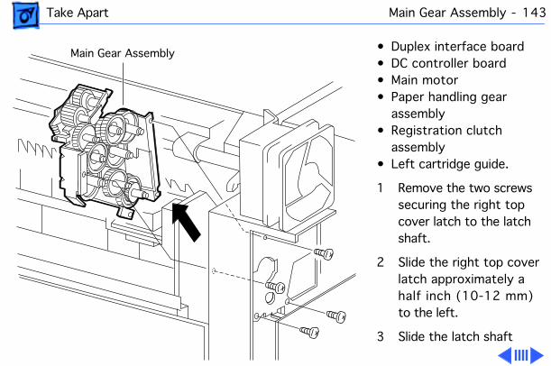
Take Apart Main Gear Assembly - 143
• Duplex interface board• DC controller board• Main motor• Paper handling gear
assembly• Registration clutch
assembly• Left cartridge guide.
1 Remove the two screws securing the right top cover latch to the latch shaft.
2 Slide the right top cover latch approximately a half inch (10-12 mm) to the left.
3 Slide the latch shaft
Main Gear Assembly
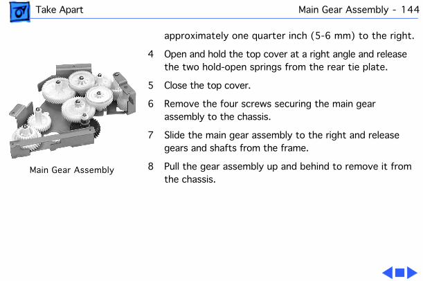
Take Apart Main Gear Assembly - 144
approximately one quarter inch (5-6 mm) to the right.
4 Open and hold the top cover at a right angle and release the two hold-open springs from the rear tie plate.
5 Close the top cover.
6 Remove the four screws securing the main gear assembly to the chassis.
7 Slide the main gear assembly to the right and release gears and shafts from the frame.
8 Pull the gear assembly up and behind to remove it from the chassis.
Main Gear Assembly
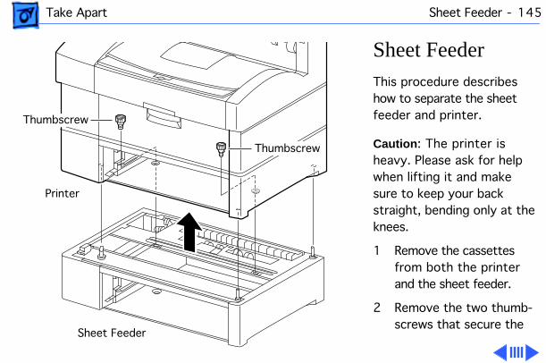
Take Apart Sheet Feeder - 145
Sheet FeederThis procedure describes how to separate the sheet feeder and printer.
Caution : The printer is heavy. Please ask for help when lifting it and make sure to keep your back straight, bending only at the knees.
1 Remove the cassettes from both the printer and the sheet feeder.
2 Remove the two thumb-screws that secure the
Sheet Feeder
Printer
Thumbscrew
Thumbscrew
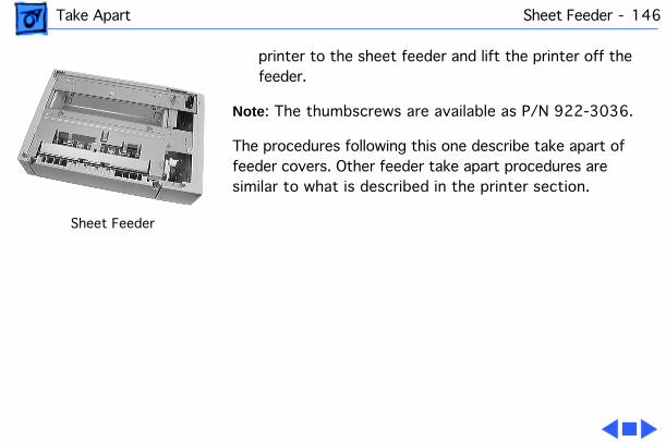
Take Apart Sheet Feeder - 146
printer to the sheet feeder and lift the printer off the feeder.
Note : The thumbscrews are available as P/N 922-3036.
The procedures following this one describe take apart of feeder covers. Other feeder take apart procedures are similar to what is described in the printer section.
Sheet Feeder
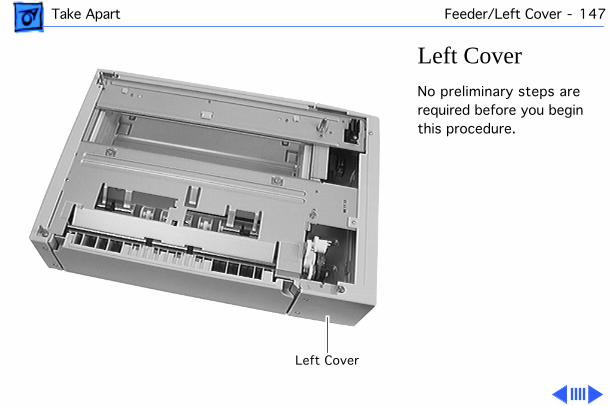
Take Apart Feeder/Left Cover - 147
Left CoverNo preliminary steps are required before you begin this procedure.
Left Cover
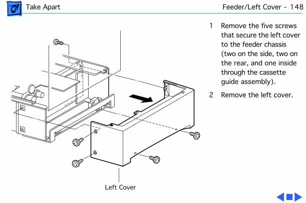
Take Apart Feeder/Left Cover - 148
1 Remove the five screws that secure the left cover to the feeder chassis (two on the side, two on the rear, and one inside through the cassette guide assembly).
2 Remove the left cover.
Left Cover
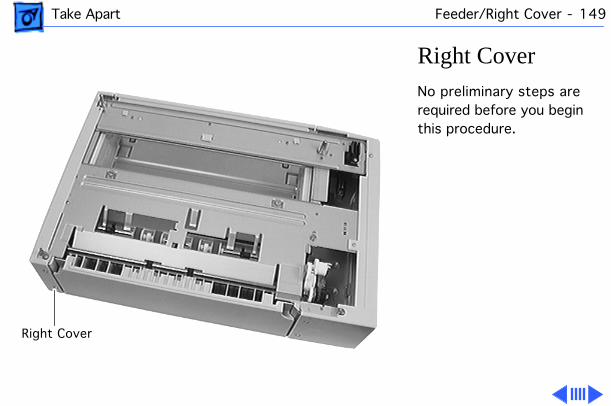
Take Apart Feeder/Right Cover - 149
Right CoverNo preliminary steps are required before you begin this procedure.
Right Cover
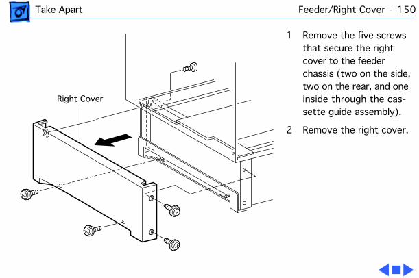
Take Apart Feeder/Right Cover - 150
1 Remove the five screws that secure the right cover to the feeder chassis (two on the side, two on the rear, and one inside through the cas-sette guide assembly).
2 Remove the right cover.
Right Cover
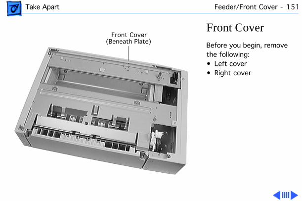
Take Apart Feeder/Front Cover - 151
Front CoverBefore you begin, remove the following:• Left cover• Right cover
Front Cover(Beneath Plate)
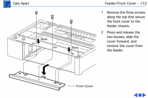
Take Apart Feeder/Front Cover - 152
1 Remove the three screws along the top that secure the front cover to the feeder chassis.
2 Press and release the two bosses, slide the cover forward, and remove the cover from the feeder.
Front Cover
Boss
Boss
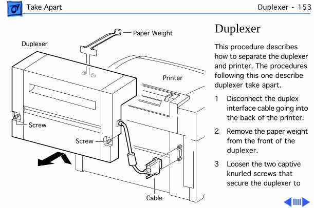
Take Apart Duplexer - 153
DuplexerThis procedure describes how to separate the duplexer and printer. The procedures following this one describe duplexer take apart.
1 Disconnect the duplex interface cable going into the back of the printer.
2 Remove the paper weight from the front of the duplexer.
3 Loosen the two captive knurled screws that secure the duplexer to
Paper Weight
Screw
Screw
Duplexer
Printer
Cable
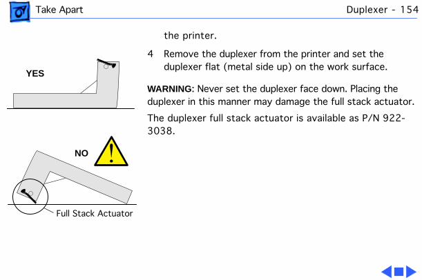
Take Apart Duplexer - 154
the printer.
4 Remove the duplexer from the printer and set the duplexer flat (metal side up) on the work surface.
WARNING: Never set the duplexer face down. Placing the duplexer in this manner may damage the full stack actuator.
The duplexer full stack actuator is available as P/N 922-3038.
Full Stack Actuator
YES
NO
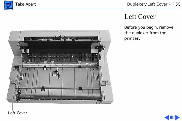
Take Apart Duplexer/Left Cover - 155
Left CoverBefore you begin, remove the duplexer from the printer.
Left Cover
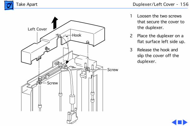
Take Apart Duplexer/Left Cover - 156
1 Loosen the two screws that secure the cover to the duplexer.
2 Place the duplexer on a flat surface left side up.
3 Release the hook and slip the cover off the duplexer.
Left Cover
Screw
Screw
Hook
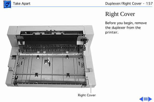
Take Apart Duplexer/Right Cover - 157
Right CoverBefore you begin, remove the duplexer from the printer.
Right Cover
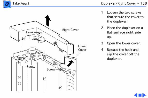
Take Apart Duplexer/Right Cover - 158
1 Loosen the two screws that secure the cover to the duplexer.
2 Place the duplexer on a flat surface right side up.
3 Open the lower cover.
4 Release the hook and slip the cover off the duplexer.
Right CoverHook
ScrewScrew
LowerCover
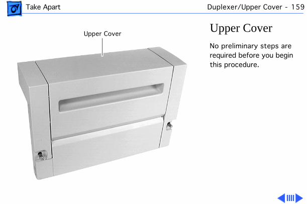
Take Apart Duplexer/Upper Cover - 159
Upper CoverNo preliminary steps are required before you begin this procedure.
Upper Cover
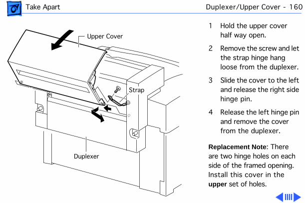
Take Apart Duplexer/Upper Cover - 160
1 Hold the upper cover half way open.
2 Remove the screw and let the strap hinge hang loose from the duplexer.
3 Slide the cover to the left and release the right side hinge pin.
4 Release the left hinge pin and remove the cover from the duplexer.
Replacement Note : There are two hinge holes on each side of the framed opening. Install this cover in the upper set of holes.
Upper Cover
Strap
Duplexer
Take Apart Duplexer/Upper Cover - 161
5 Perform the “Taping The Paper-Pass Actuator” procedure if you have also removed the lower cover.
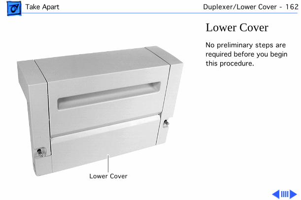
Take Apart Duplexer/Lower Cover - 162
Lower CoverNo preliminary steps are required before you begin this procedure.
Lower Cover
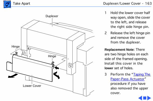
Take Apart Duplexer/Lower Cover - 163
1 Hold the lower cover half way open, slide the cover to the left, and release the right side hinge pin.
2 Release the left hinge pin and remove the cover from the duplexer.
Replacement Note : There are two hinge holes on each side of the framed opening. Install this cover in the lower set of holes.
3 Perform the “Taping The Paper-Pass Actuator” procedure if you have also removed the upper cover.
Duplexer
Lower Cover
Hinge
Hinge
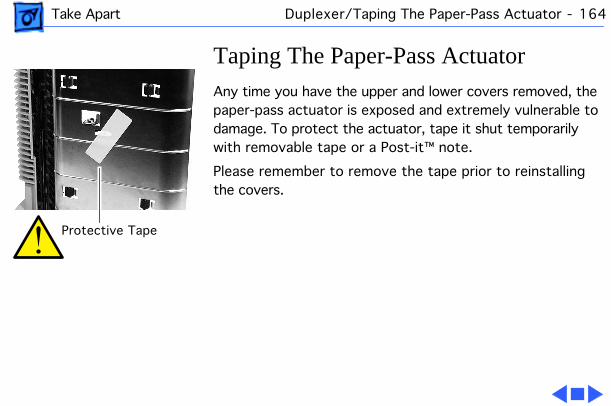
Take Apart Duplexer/Taping The Paper-Pass Actuator - 164
Taping The Paper-Pass ActuatorAny time you have the upper and lower covers removed, the paper-pass actuator is exposed and extremely vulnerable to damage. To protect the actuator, tape it shut temporarily with removable tape or a Post-it™ note.
Please remember to remove the tape prior to reinstalling the covers.
Protective Tape
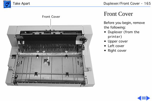
Take Apart Duplexer/Front Cover - 165
Front CoverBefore you begin, remove the following:• Duplexer (from the
printer)• Upper cover• Left cover• Right cover
Front Cover
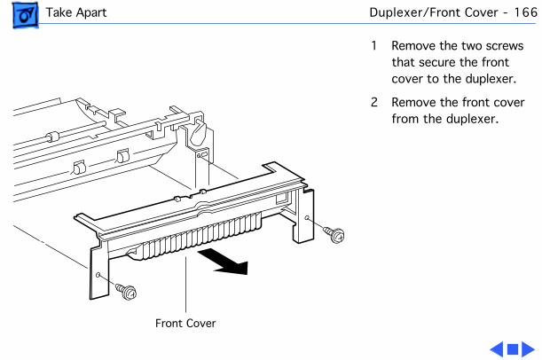
Take Apart Duplexer/Front Cover - 166
1 Remove the two screws that secure the front cover to the duplexer.
2 Remove the front cover from the duplexer.
Front Cover
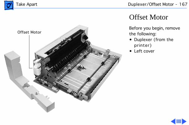
Take Apart Duplexer/Offset Motor - 167
Offset MotorBefore you begin, remove the following:• Duplexer (from the
printer)• Left cover
Offset Motor
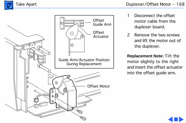
Take Apart Duplexer/Offset Motor - 168
1 Disconnect the offset motor cable from the duplexer board.
2 Remove the two screws and lift the motor out of the duplexer.
Replacement Note: Tilt the motor slightly to the right and insert the offset actuator into the offset guide arm.
Offset Motor
Offset Guide Arm
OffsetActuator
Guide Arm/Actuator PositionDuring Replacement
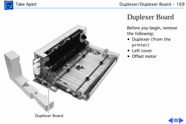
Take Apart Duplexer/Duplexer Board - 169
Duplexer BoardBefore you begin, remove the following:• Duplexer (from the
printer)• Left cover• Offset motor
Duplexer Board
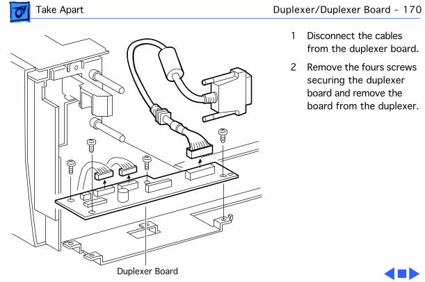
Take Apart Duplexer/Duplexer Board - 170
1 Disconnect the cables from the duplexer board.
2 Remove the fours screws securing the duplexer board and remove the board from the duplexer.
Duplexer Board
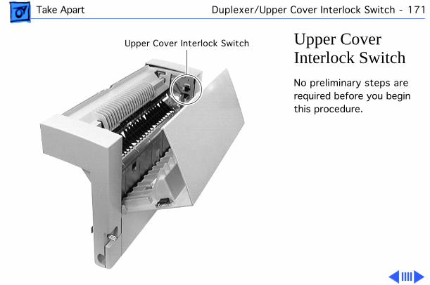
Take Apart Duplexer/Upper Cover Interlock Switch - 171
Upper Cover Interlock SwitchNo preliminary steps are required before you begin this procedure.
Upper Cover Interlock Switch
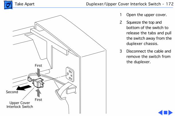
Take Apart Duplexer/Upper Cover Interlock Switch - 172
1 Open the upper cover.
2 Squeeze the top and bottom of the switch to release the tabs and pull the switch away from the duplexer chassis.
3 Disconnect the cable and remove the switch from the duplexer.
First
First
Second
Upper CoverInterlock Switch
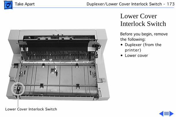
Take Apart Duplexer/Lower Cover Interlock Switch - 173
Lower Cover Interlock SwitchBefore you begin, remove the following:• Duplexer (from the
printer)• Lower cover
Lower Cover Interlock Switch
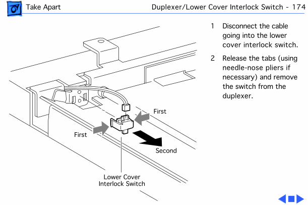
Take Apart Duplexer/Lower Cover Interlock Switch - 174
1 Disconnect the cable going into the lower cover interlock switch.
2 Release the tabs (using needle-nose pliers if necessary) and remove the switch from the duplexer.
First
First
Second
Lower CoverInterlock Switch

Take Apart Duplexer/Paper-Pass Sensor - 175
Paper-Pass SensorBefore you begin, remove the duplexer from the printer.
Paper-Pass Sensor
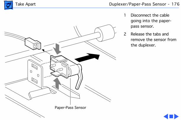
Take Apart Duplexer/Paper-Pass Sensor - 176
1 Disconnect the cable going into the paper-pass sensor.
2 Release the tabs and remove the sensor from the duplexer.
Paper-Pass Sensor
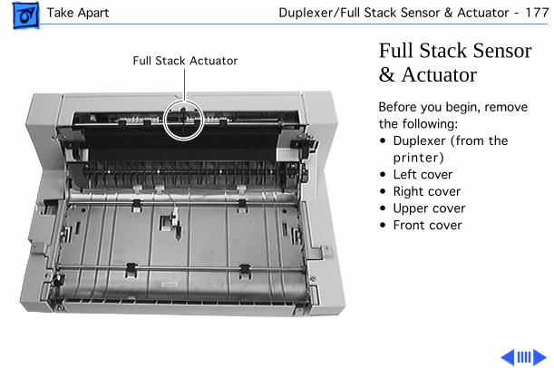
Take Apart Duplexer/Full Stack Sensor & Actuator - 177
Full Stack Sensor & ActuatorBefore you begin, remove the following:• Duplexer (from the
printer)• Left cover• Right cover• Upper cover• Front cover
Full Stack Actuator
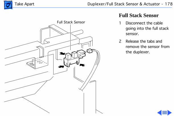
Take Apart Duplexer/Full Stack Sensor & Actuator - 178
Full Stack Sensor1 Disconnect the cable
going into the full stack sensor.
2 Release the tabs and remove the sensor from the duplexer.
Full Stack Sensor
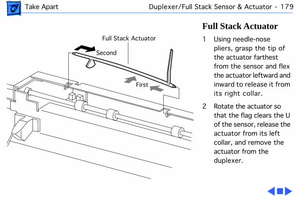
Take Apart Duplexer/Full Stack Sensor & Actuator - 179
Full Stack Actuator1 Using needle-nose
pliers, grasp the tip of the actuator farthest from the sensor and flex the actuator leftward and inward to release it from its right collar.
2 Rotate the actuator so that the flag clears the U of the sensor, release the actuator from its left collar, and remove the actuator from the duplexer.
Full Stack Actuator
First
Second

Take Apart Duplexer/Offset Guide Arm - 180
Offset Guide ArmBefore you begin, remove the following:• Duplexer (from the
printer)• Left cover
Offset Guide Arm
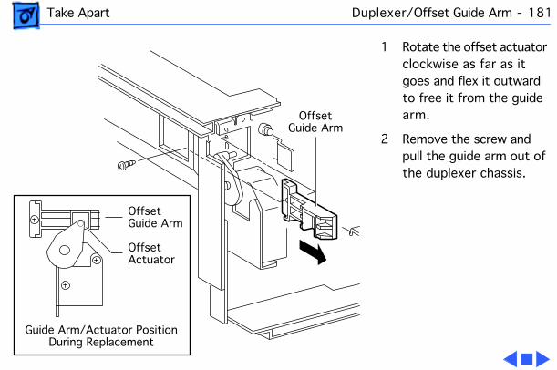
Take Apart Duplexer/Offset Guide Arm - 181
1 Rotate the offset actuator clockwise as far as it goes and flex it outward to free it from the guide arm.
2 Remove the screw and pull the guide arm out of the duplexer chassis.
Offset Guide Arm
Offset Guide Arm
OffsetActuator
Guide Arm/Actuator PositionDuring Replacement
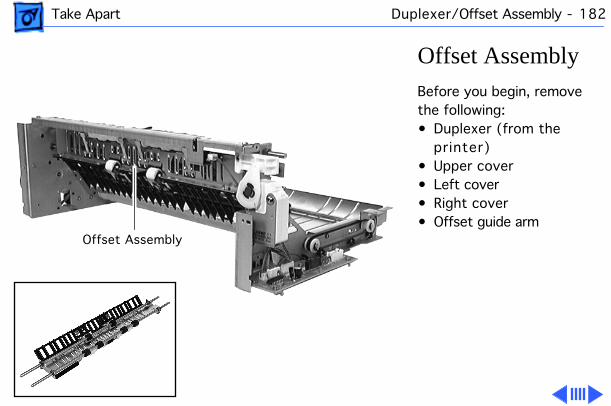
Take Apart Duplexer/Offset Assembly - 182
Offset AssemblyBefore you begin, remove the following:• Duplexer (from the
printer)• Upper cover• Left cover• Right cover• Offset guide arm
Offset Assembly
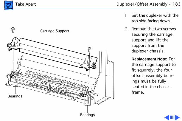
Take Apart Duplexer/Offset Assembly - 183
1 Set the duplexer with the top side facing down.
2 Remove the two screws securing the carriage support and lift the support from the duplexer chassis.
Replacement Note : For the carriage support to fit squarely, the four offset assembly bear-ings must be fully seated in the chassis frame.
Carriage Support
Bearings
Bearings
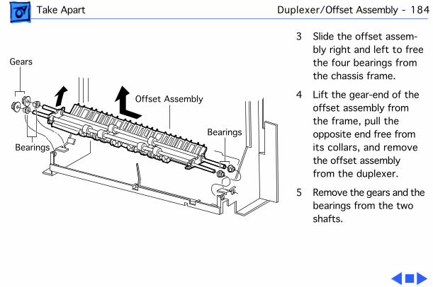
Take Apart Duplexer/Offset Assembly - 184
3 Slide the offset assem-bly right and left to free the four bearings from the chassis frame.
4 Lift the gear-end of the offset assembly from the frame, pull the opposite end free from its collars, and remove the offset assembly from the duplexer.
5 Remove the gears and the bearings from the two shafts.
Offset Assembly
Bearings
Bearings
Gears
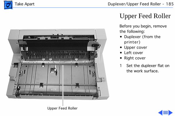
Take Apart Duplexer/Upper Feed Roller - 185
Upper Feed RollerBefore you begin, remove the following:• Duplexer (from the
printer)• Upper cover• Left cover• Right cover
1 Set the duplexer flat on the work surface.
Upper Feed Roller
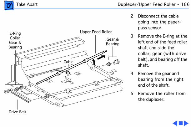
Take Apart Duplexer/Upper Feed Roller - 186
2 Disconnect the cable going into the paper-pass sensor.
3 Remove the E-ring at the left end of the feed roller shaft and slide the collar, gear (with drive belt), and bearing off the shaft.
4 Remove the gear and bearing from the right end of the shaft.
5 Remove the roller from the duplexer.
Drive Belt
Upper Feed RollerE-RingCollarGear &Bearing
Gear &Bearing
Cable

Take Apart Duplexer/Lower Feed Roller - 187
Lower Feed RollerBefore you begin, remove the following:• Duplexer (from the
printer)• Upper cover• Left cover• Right cover
1 Set the duplexer flat on the work surface.
Lower Feed Roller
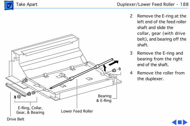
Take Apart Duplexer/Lower Feed Roller - 188
2 Remove the E-ring at the left end of the feed roller shaft and slide the collar, gear (with drive belt), and bearing off the shaft.
3 Remove the E-ring and bearing from the right end of the shaft.
4 Remove the roller from the duplexer.
Drive Belt
Bearing& E-Ring
E-Ring, Collar, Gear, & Bearing Lower Feed Roller
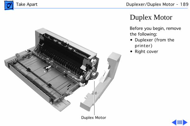
Take Apart Duplexer/Duplex Motor - 189
Duplex MotorBefore you begin, remove the following:• Duplexer (from the
printer)• Right cover
Duplex Motor
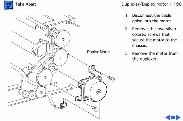
Take Apart Duplexer/Duplex Motor - 190
1 Disconnect the cable going into the motor.
2 Remove the two silver-colored screws that secure the motor to the chassis.
3 Remove the motor from the duplexer.
Duplex Motor

Table of Contents August 1997
General .............................................................................1
Fuser Access Cover ..........................................................2
Left Top Cover ...................................................................4
Left Cover Assembly .........................................................7
Front Left Cover .................................................................9
Left Lower Cover .............................................................11
Right Top Cover ...............................................................13
Right Cover .....................................................................16
Exit Cover ........................................................................18
Top Cover ........................................................................20
Front Cover ......................................................................22
Turn-In Chute ..................................................................24
Turn Chute Cover ............................................................25
Fuser Assembly ...............................................................27
I/O Board .........................................................................29
Cassette Feeder Board ...................................................33
Duplex Interface Board ....................................................36
DC Controller Board ........................................................39
Fan ..................................................................................43
Power Supply ..................................................................45
High-Voltage Power Supply .............................................50
Main Motor ......................................................................54
Paper Handling Gear Assembly ......................................57
Registration Clutch Assembly .........................................60
Turn Clutch ......................................................................62
Left Cassette Guide Assembly ........................................64
Cassette Paper-Present Sensor ......................................68
Right Cassette Guide Assembly ......................................70
Cassette Paper-Present Actuator ....................................72
Cassette Pickup Roller(s) ................................................74
Cassette Pickup Solenoid ...............................................76
Lower Feed Roller ...........................................................78
Upper Feed Roller ...........................................................80
Top Cover Housing ..........................................................82
Laser/Scanner Assembly ............................................88
Cartridge Sensor Assembly ........................................93
Manual Feed Sensor Assembly ......................................95
Manual Feed Paper-Present Sensor ...............................98
Manual Feed Paper-Present Actuator ...........................100
Toner Sensor Assembly ................................................102
Transfer Roller Assembly ...............................................104
Manual Feed Pickup Roller ...........................................106
Manual Feed Pickup Solenoid .......................................108
Separation Pad Assembly .............................................112
Registration Sensor Assembly ......................................116
Full Stack Sensor & Actuator ........................................118
Transport Chute Assembly ............................................122
Manual Feed Pickup Roller Assembly .......................... 126
Left Cartridge Guide Assembly ..................................... 129
Right Cartridge Guide Assembly .................................. 133
Manual Feed Guide Tray ............................................... 135
Top Cover Interlock Switch ........................................... 137
Fuser Cover Interlock Switch ........................................ 139
Main Gear Assembly ..................................................... 142
Sheet Feeder ................................................................ 145
Left Cover ................................................................. 147
Right Cover ............................................................... 149
Front Cover ............................................................... 151
Duplexer ........................................................................ 153
Left Cover ................................................................. 155
Right Cover ............................................................... 157
Upper Cover .............................................................. 159
Lower Cover .............................................................. 162
Taping The Paper-Pass Actuator .............................. 164
Front Cover ............................................................... 165
Offset Motor .............................................................. 167
Duplexer Board ......................................................... 169
Upper Cover Interlock Switch ................................... 171
Lower Cover Interlock Switch ................................... 173
Paper-Pass Sensor ................................................... 175
Full Stack Sensor & Actuator .................................... 177
Offset Guide Arm ...................................................... 180
Offset Assembly ........................................................ 182
Upper Feed Roller ..................................................... 185
Lower Feed Roller ..................................................... 187
Duplex Motor ............................................................. 189
Take Apart

Service Source
K
Troubleshooting
LaserWriter 8500
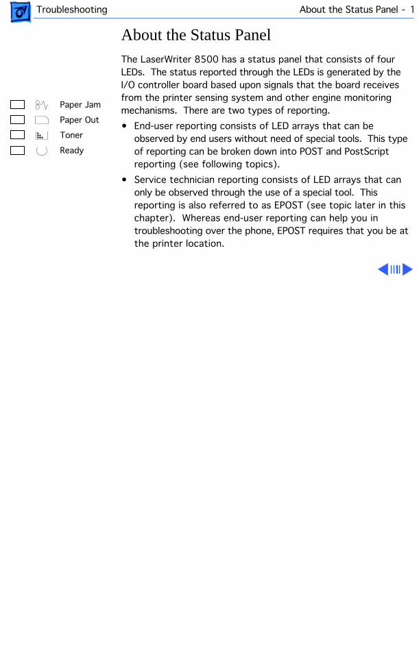
Troubleshooting About the Status Panel - 1
About the Status Panel
The LaserWriter 8500 has a status panel that consists of four LEDs. The status reported through the LEDs is generated by the I/O controller board based upon signals that the board receives from the printer sensing system and other engine monitoring mechanisms. There are two types of reporting.
• End-user reporting consists of LED arrays that can be observed by end users without need of special tools. This type of reporting can be broken down into POST and PostScript reporting (see following topics).
• Service technician reporting consists of LED arrays that can only be observed through the use of a special tool. This reporting is also referred to as EPOST (see topic later in this chapter). Whereas end-user reporting can help you in troubleshooting over the phone, EPOST requires that you be at the printer location.
Paper Jam
Paper Out
Toner
Ready

Troubleshooting POST (Power-On Self Test) - 2
POST (Power-On Self Test)
When you switch on power, all the status panel LEDs illuminate briefly. This confirms that power is getting to the status panel and that all LEDs are operational. All LEDs then extinguish and come back on. This marks the start of POST.
POST is a set of diagnostic procedures that are written into firmware on the I/O controller board. POST executes in the first 10 seconds of startup and checks the following three areas of the printer in order:
• Stage 1 I/O controller (ROM & SIMMs)
• Stage 2 I/O controller (miscellaneous circuitry)
• Stage 3 D/C controller board

Troubleshooting POST (Power-On Self Test) - 3
Stage Failure/POST
POST extinguishes the LEDs from front to back as each test stage passes. (The Ready LED is considered here to be the front LED). In a functional printer, the testing process takes about 40 seconds, after which control passes to PostScript code in ROM and the normal warmup continues (see “PostScript Reporting” in this chapter).
However, if POST detects a fault during any stage, the status panel enters an error state and flashes the paper-out and paper-jam LEDs forever. Making note of the stage from which this error array first appears can help you choose the modules to bring on a service call.
For example, suppose failure occurs during stage two (only the Ready LED had extinguished before the error array appears). This indicates an I/O board failure, so a replacement board should definitely accompany you on site.

Troubleshooting PostScript Reporting - 4
PostScript Reporting
PostScript reporting starts as soon as POST is completed. Most of the time, PostScript will report according to the literal designation of the LED. (For example, the paper-out LED illuminates when the paper cassette is empty). However, there are some instances where closer observation is critical in interpreting the status panel.
• Solid ready light: In some cases, the ready light will illuminate for as long as 15 seconds before a PostScript fault is reported. Make sure to wait this extra time for PostScript to execute before shutting down to perform further troubleshooting.
• Behavior before PostScript error: As with stage-reporting during POST, it is sometimes necessary to note what occurs
before
the error array first appears. The chart on the following page notes where this is important.
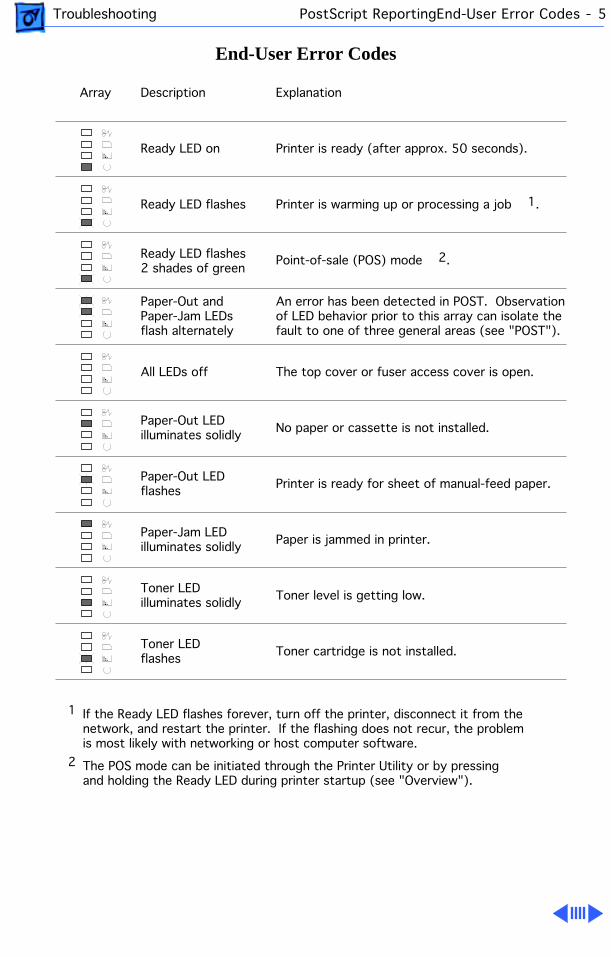
Troubleshooting PostScript ReportingEnd-User Error Codes - 5
End-User Error Codes
Ready LED on
Paper-Out and Paper-Jam LEDsflash alternately
Description Explanation
Printer is ready (after approx. 50 seconds).
An error has been detected in POST. Observationof LED behavior prior to this array can isolate thefault to one of three general areas (see "POST").
The top cover or fuser access cover is open.
Paper is jammed in printer.
No paper or cassette is not installed.
Toner level is getting low.
Array
All LEDs off
Paper-Jam LED illuminates solidly
Toner LED illuminates solidly
Paper-Out LEDilluminates solidly
1 If the Ready LED flashes forever, turn off the printer, disconnect it from the network, and restart the printer. If the flashing does not recur, the problemis most likely with networking or host computer software.
2 The POS mode can be initiated through the Printer Utility or by pressingand holding the Ready LED during printer startup (see "Overview").
Ready LED flashes Printer is warming up or processing a job 1.
Printer is ready for sheet of manual-feed paper.Paper-Out LEDflashes
Toner cartridge is not installed.Toner LED flashes
Ready LED flashes2 shades of green
Point-of-sale (POS) mode 2.

Troubleshooting EPOST (Extended Power-On Self Test) - 6
EPOST (Extended Power-On Self Test)
EPOST behaves exactly like POST in that it checks the same three areas in the same order and displays an error array if a fault is detected. However, EPOST has more extensive testing and its error arrays are completely different. When a fault is detected during EPOST, all LEDs extinguish and the status panel will loop through the following sequence until you switch off power:
•
All LEDs On
for approximately one second
•
All LEDs Off
for approximately one second
•
EPOST Error Code
for approximately one second
•
All LEDs Off
for approximately two seconds, then repeat loop
If no error is detected by EPOST, an EPOST test page will print before control is passed on to the PostScript interpreter.
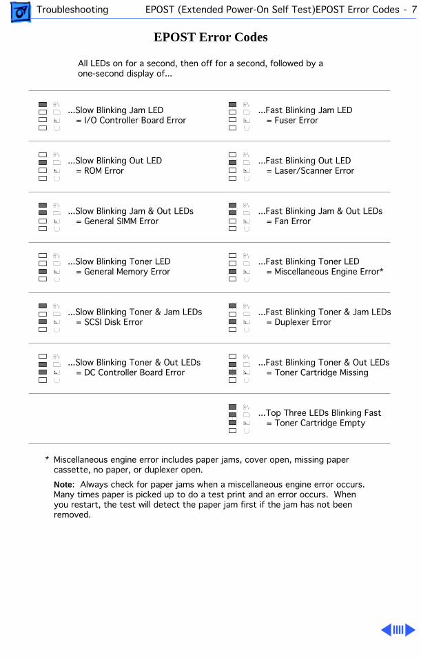
Troubleshooting EPOST (Extended Power-On Self Test)EPOST Error Codes - 7
EPOST Error Codes
All LEDs on for a second, then off for a second, followed by a one-second display of...
...Fast Blinking Jam LED = Fuser Error
...Fast Blinking Out LED = Laser/Scanner Error
...Fast Blinking Jam & Out LEDs = Fan Error
...Fast Blinking Toner LED = Miscellaneous Engine Error*
...Fast Blinking Toner & Jam LEDs = Duplexer Error
...Fast Blinking Toner & Out LEDs = Toner Cartridge Missing
...Top Three LEDs Blinking Fast = Toner Cartridge Empty
Miscellaneous engine error includes paper jams, cover open, missing papercassette, no paper, or duplexer open.
Note: Always check for paper jams when a miscellaneous engine error occurs.Many times paper is picked up to do a test print and an error occurs. Whenyou restart, the test will detect the paper jam first if the jam has not beenremoved.
*
...Slow Blinking Jam LED = I/O Controller Board Error
...Slow Blinking Out LED = ROM Error
...Slow Blinking Jam & Out LEDs = General SIMM Error
...Slow Blinking Toner LED = General Memory Error
...Slow Blinking Toner & Jam LEDs = SCSI Disk Error
...Slow Blinking Toner & Out LEDs = DC Controller Board Error

Troubleshooting EPOST (Extended Power-On Self Test)Initiating EPOST - 8
Initiating EPOST
To initiate EPOST, you must have the printer loopback test plug (P/N 922-1489). This test plug is colored bright green to differentiate it from an older version black plug. Do not use the black plug on the LaserWriter 8500. It won’t harm anything; it just won’t work.
Switch off the printer and install the test plug into the LocalTalk port on the back of the I/O controller board. Switch the printer back on.
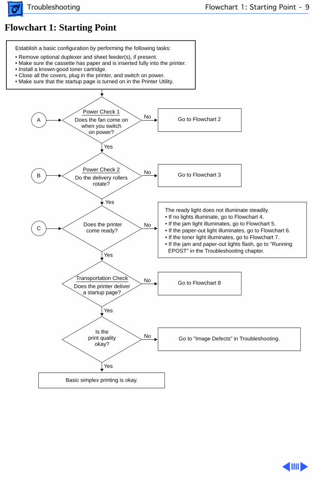
Troubleshooting Flowchart 1: Starting Point - 9
Flowchart 1: Starting Point
Establish a basic configuration by performing the following tasks:
• Remove optional duplexer and sheet feeder(s), if present.• Make sure the cassette has paper and is inserted fully into the printer.• Install a known-good toner cartridge.• Close all the covers, plug in the printer, and switch on power.• Make sure that the startup page is turned on in the Printer Utility.
Power Check 1
Does the fan come onwhen you switch
on power?
Power Check 2
Do the delivery rollersrotate?
Does the printer come ready?
The ready light does not illuminate steadily.• If no lights illuminate, go to Flowchart 4.• If the jam light illuminates, go to Flowchart 5.• If the paper-out light illuminates, go to Flowchart 6.• If the toner light illuminates, go to Flowchart 7.• If the jam and paper-out lights flash, go to "Running EPOST" in the Troubleshooting chapter.
Transportation Check
Does the printer deliver a startup page?
Is theprint quality
okay?
Basic simplex printing is okay.
Yes
No
No
No
A
No
No
Yes
Yes
Yes
Yes
Go to "Image Defects" in Troubleshooting.
Go to Flowchart 3
Go to Flowchart 8
Go to Flowchart 2
B
C
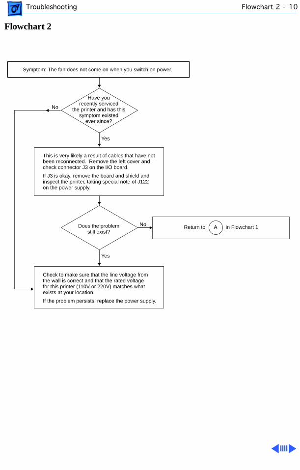
Troubleshooting Flowchart 2 - 10
Flowchart 2
Symptom: The fan does not come on when you switch on power.
This is very likely a result of cables that have notbeen reconnected. Remove the left cover and check connector J3 on the I/O board.
If J3 is okay, remove the board and shield and inspect the printer, taking special note of J122 on the power supply.
Have you recently serviced
the printer and has this symptom existed
ever since?
Does the problem still exist?
Yes
Yes
No
No
Check to make sure that the line voltage fromthe wall is correct and that the rated voltagefor this printer (110V or 220V) matches whatexists at your location.
If the problem persists, replace the power supply.
Return to A in Flowchart 1
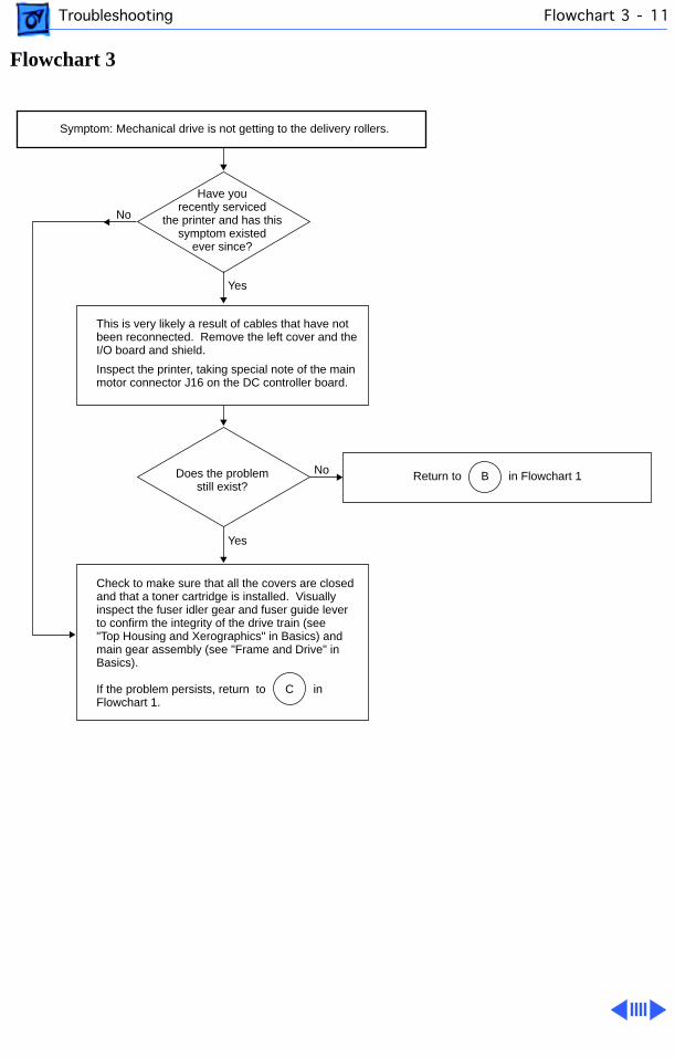
Troubleshooting Flowchart 3 - 11
Flowchart 3
Symptom: Mechanical drive is not getting to the delivery rollers.
This is very likely a result of cables that have notbeen reconnected. Remove the left cover and theI/O board and shield.
Inspect the printer, taking special note of the main motor connector J16 on the DC controller board.
Have you recently serviced
the printer and has this symptom existed
ever since?
Does the problem still exist?
Yes
Yes
No
No
Check to make sure that all the covers are closedand that a toner cartridge is installed. Visuallyinspect the fuser idler gear and fuser guide leverto confirm the integrity of the drive train (see"Top Housing and Xerographics" in Basics) andmain gear assembly (see "Frame and Drive" inBasics).
If the problem persists, return to C inFlowchart 1.
Return to B in Flowchart 1
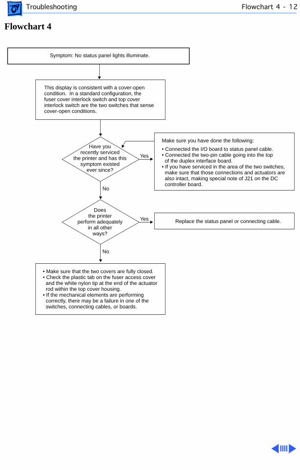
Troubleshooting Flowchart 4 - 12
Flowchart 4
Symptom: No status panel lights illuminate.
This display is consistent with a cover-opencondition. In a standard configuration, thefuser cover interlock switch and top coverinterlock switch are the two switches that sensecover-open conditions.
Have you recently serviced
the printer and has this symptom existed
ever since?
Make sure you have done the following:
• Connected the I/O board to status panel cable.• Connected the two-pin cable going into the top of the duplex interface board. • If you have serviced in the area of the two switches, make sure that those connections and actuators are also intact, making special note of J21 on the DC controller board.
Replace the status panel or connecting cable.
• Make sure that the two covers are fully closed.• Check the plastic tab on the fuser access cover and the white nylon tip at the end of the actuator rod within the top cover housing.• If the mechanical elements are performing correctly, there may be a failure in one of the switches, connecting cables, or boards.
No
Doesthe printer
perform adequatelyin all other
ways?
No
Yes
Yes
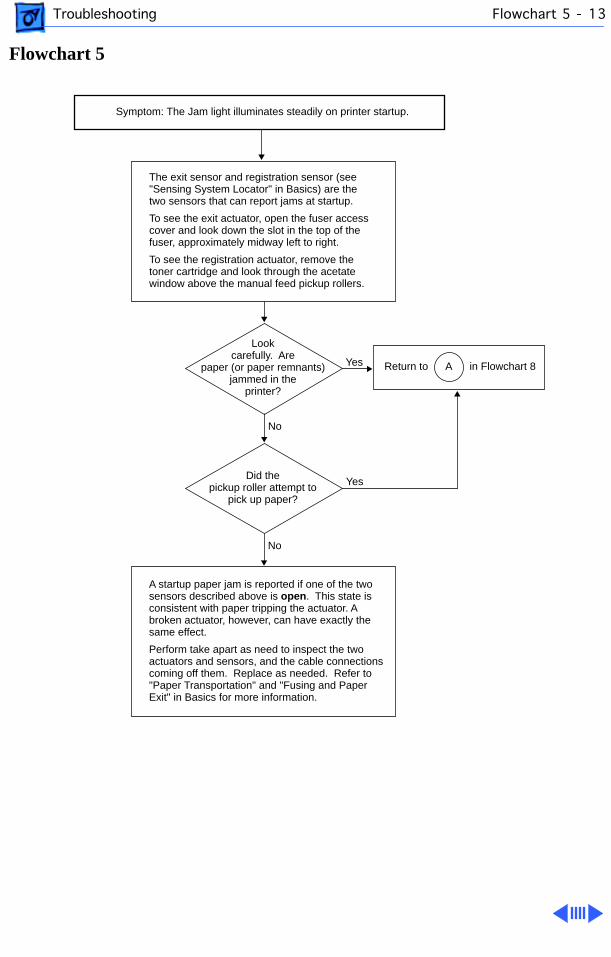
Troubleshooting Flowchart 5 - 13
Flowchart 5
Symptom: The Jam light illuminates steadily on printer startup.
The exit sensor and registration sensor (see "Sensing System Locator" in Basics) are the two sensors that can report jams at startup.
To see the exit actuator, open the fuser accesscover and look down the slot in the top of thefuser, approximately midway left to right.
To see the registration actuator, remove the toner cartridge and look through the acetatewindow above the manual feed pickup rollers.
Look carefully. Are
paper (or paper remnants) jammed in the
printer?
Did the pickup roller attempt to
pick up paper?
No
No
Yes
Yes
A startup paper jam is reported if one of the two sensors described above is open. This state is consistent with paper tripping the actuator. A broken actuator, however, can have exactly the same effect.
Perform take apart as need to inspect the twoactuators and sensors, and the cable connectionscoming off them. Replace as needed. Refer to"Paper Transportation" and "Fusing and PaperExit" in Basics for more information.
Return to A in Flowchart 8
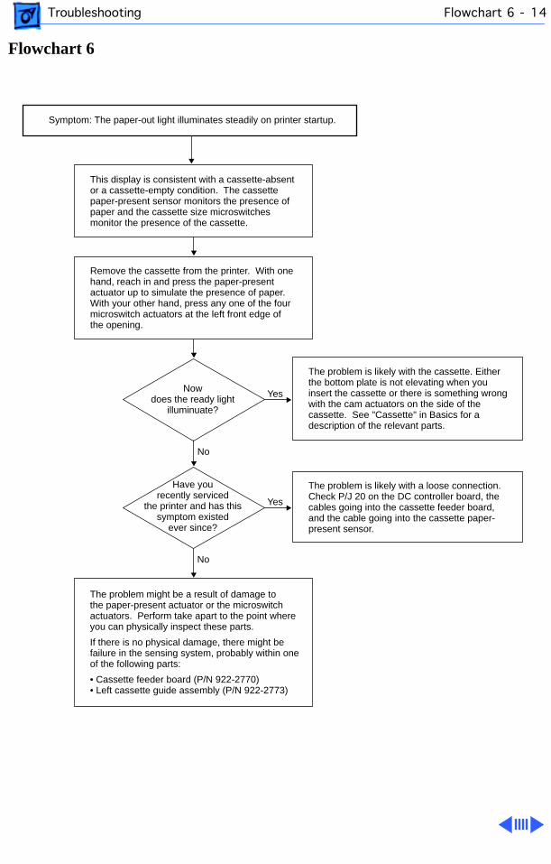
Troubleshooting Flowchart 6 - 14
Flowchart 6
Symptom: The paper-out light illuminates steadily on printer startup.
Remove the cassette from the printer. With onehand, reach in and press the paper-presentactuator up to simulate the presence of paper.With your other hand, press any one of the fourmicroswitch actuators at the left front edge ofthe opening.
Now does the ready light
illuminuate?
No
No
Yes
This display is consistent with a cassette-absentor a cassette-empty condition. The cassettepaper-present sensor monitors the presence ofpaper and the cassette size microswitchesmonitor the presence of the cassette.
The problem might be a result of damage tothe paper-present actuator or the microswitchactuators. Perform take apart to the point whereyou can physically inspect these parts.
If there is no physical damage, there might befailure in the sensing system, probably within oneof the following parts:
• Cassette feeder board (P/N 922-2770)• Left cassette guide assembly (P/N 922-2773)
The problem is likely with the cassette. Either the bottom plate is not elevating when you insert the cassette or there is something wrongwith the cam actuators on the side of the cassette. See "Cassette" in Basics for a description of the relevant parts.
Yes
The problem is likely with a loose connection.Check P/J 20 on the DC controller board, thecables going into the cassette feeder board, and the cable going into the cassette paper-present sensor.
Have you recently serviced
the printer and has this symptom existed
ever since?
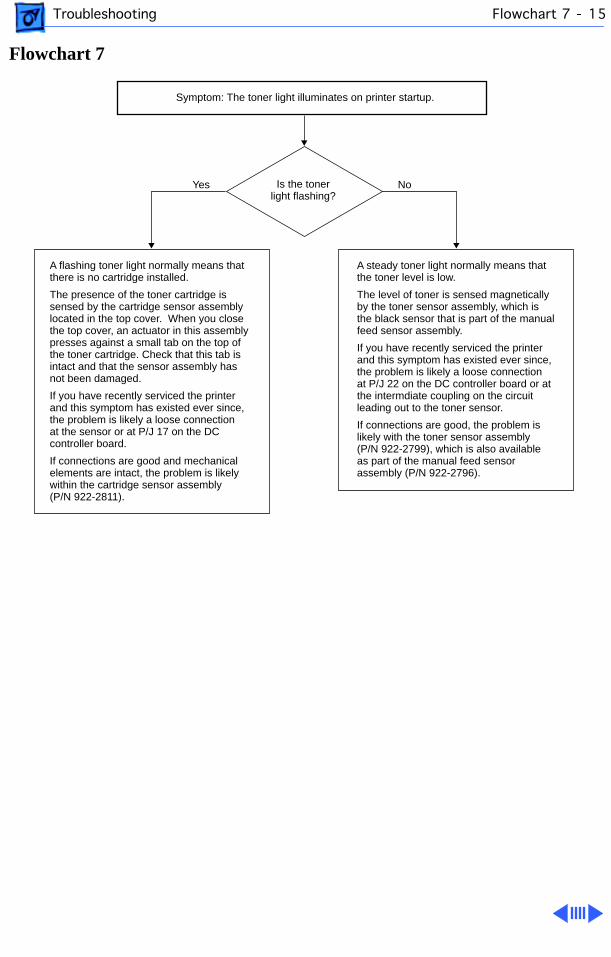
Troubleshooting Flowchart 7 - 15
Flowchart 7
Symptom: The toner light illuminates on printer startup.
A flashing toner light normally means that there is no cartridge installed.
The presence of the toner cartridge issensed by the cartridge sensor assemblylocated in the top cover. When you closethe top cover, an actuator in this assemblypresses against a small tab on the top ofthe toner cartridge. Check that this tab is intact and that the sensor assembly has not been damaged.
If you have recently serviced the printer and this symptom has existed ever since,the problem is likely a loose connectionat the sensor or at P/J 17 on the DC controller board.
If connections are good and mechanicalelements are intact, the problem is likelywithin the cartridge sensor assembly (P/N 922-2811).
A steady toner light normally means that the toner level is low.
The level of toner is sensed magneticallyby the toner sensor assembly, which isthe black sensor that is part of the manualfeed sensor assembly.
If you have recently serviced the printer and this symptom has existed ever since,the problem is likely a loose connectionat P/J 22 on the DC controller board or atthe intermdiate coupling on the circuit leading out to the toner sensor.
If connections are good, the problem islikely with the toner sensor assembly (P/N 922-2799), which is also availableas part of the manual feed sensorassembly (P/N 922-2796).
Is the toner light flashing?
Yes No
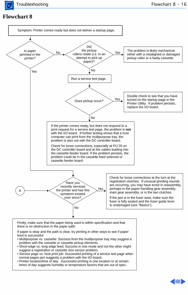
Troubleshooting Flowchart 8 - 16
Flowchart 8
Symptom: Printer comes ready but does not deliver a startup page.
Run a service test page.
If the printer comes ready, but does not respond to a print request for a service test page, the problem is not with the I/O board. If further testing shows that a host computer can print from the multipurpose tray, the problem is also not with the DC controller board.
Check for loose connections, especially at P/J 20 on the DC controller board and at the cables leading into the cassette feeder board. If the problem persists, the problem could be in the cassette feed solenoid or cassette feeder board.
The problem is likely mechanical,either with a misaligned or damaged pickup roller or a faulty cassette.
Double check to see that you haveturned on the startup page in the Printer Utility. If problem persists,replace the I/O board.
Check for loose connections at the turn at the registration clutches. If unusual grinding sounds are occurring, you may have erred in reassembly, perhaps in the paper-handling gear assembly, main gear assembly, or in the two clutches.
If the jam is in the fuser area, make sure the fuser is fully seated and the fuser guide lever is undamaged (see "Basics").
Firstly, make sure that the paper being used is within specification and that there is no obstruction in the paper path.
If paper is okay and the path is clear, try printing in other ways to see if paper feed is successful:• Multipurpose vs. cassette: Success from the multipurpose tray may suggest a problem with the cassette or cassette pickup elements.• Short-edge vs. long-edge feed: Success in one mode and not the other might suggest a registration or cassette size sensor problem.• Service page vs. host print job: Successful printing of a service test page when normal pages jam suggests a problem with the I/O board.• Printer location/time of day: Successful printing in one location or at certain times of day suggests humidity or temperature factors that are out of spec.
No Yes
Yes
Yes
Is paperjammed in the
printer?
Didthe pickup
rollers rotate (i.e. in anattempt to pick up
paper)?
Yes No
No
No
Have you recently serviced
the printer and has this symptom existed
ever since?
Does pickup occur?
A
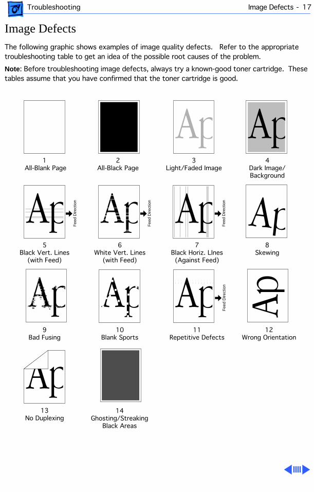
Troubleshooting Image Defects - 17
Image Defects
The following graphic shows examples of image quality defects. Refer to the appropriate troubleshooting table to get an idea of the possible root causes of the problem.
Note
: Before troubleshooting image defects, always try a known-good toner cartridge. These tables assume that you have confirmed that the toner cartridge is good.
1 All-Blank Page
5Black Vert. Lines
(with Feed)
4Dark Image/Background
6White Vert. Lines
(with Feed)
7Black Horiz. LInes(Against Feed)
9Bad Fusing
13No Duplexing
10Blank Sports
11Repetitive Defects
12Wrong Orientation
8Skewing
2All-Black Page
3Light/Faded Image
Fee
d D
irect
ion
Fee
d D
irect
ion
Fee
d D
irect
ion
Fee
d D
irect
ion
14Ghosting/Streaking
Black Areas

Troubleshooting Image Defects - 18
1 All Blank Page
This condition suggests that the laser beam is not striking the photosensitive drum.
Check for physical obstructions, especially sealing tape that has not been removed from the cartridge or something else just outside the laser/scanner assembly.
If this condition occurs only with a certain print job, make sure that some user-defined parameter such as magnification is not unintentionally placing the entire image off the area of the page.
If the problem persists, run the EPOST diagnostic.

Troubleshooting Image Defects - 19
2 All Black Page
This condition is the result of a uniform charge on the photosensitive drum at the point where toner development takes places.
This charge can either be by design (for example, a black mask within an Illustrator document that is visible only in preview mode), or because of a failure in the charging or exposure system.
First run the EPOST diagnostic. If EPOST is inconclusive, run a service test page. If the symptom disappears, the problem is likely with the I/O board. If the symptom persists, the problem is
not
with the I/O board.
If the procedures above do not solve the problem, replace the high-voltage power supply.

Troubleshooting Image Defects - 20
3 Light/Faded Image
This condition is usually the result of inadequate charge to the imaging components.
First confirm that known-good paper is being used and the density values have not been set incorrectly (see “Density Adjustment” in the Overview chapter for the two methods of density adjustment.)
If you have recently serviced the printer and this symptom has existed ever since, the problem is almost certainly a loose connection. Carefully inspect all connections, especially connector TR going into the bottom of the high-voltage power supply (see “High-Voltage Power Supply” in Take Apart for correct orientation of the connector).
Other root causes for this symptom are faulty transfer roller or high-voltage power supply.

Troubleshooting Image Defects - 21
4 Dark Image/Background
This condition is consistent with an overly high charge being imparted to the imaging components or improper grounding of the transport chute or fuser assemblies.
Confirm that known-good paper is being used and the density values have not been set incorrectly (see “Density Adjustment” in the Overview chapter for the two methods of density adjustment.)

Troubleshooting Image Defects - 22
5 Black Vertical Lines
Run a service test page. If the symptom disappears, the problem is likely with the I/O board. If the symptom persists, the problem is
not
with the I/O board.
If the symptom persists, the problem is likely with the fuser assembly or laser/scanner assembly.
Fee
d D
irect
ion

Troubleshooting Image Defects - 23
6 White Vertical Lines
This condition is consistent with an obstructed laser beam. Check to see if there is a hair or some other obstruction that could be blocking the laser beam.
Run a service test page. If the symptom disappears, the problem is likely with the I/O board. If the symptom persists, the problem is
not
with the I/O board, but probably with the laser/scanner assembly.
Fee
d D
irect
ion

Troubleshooting Image Defects - 24
7 Black Horizontal Lines
Run a service test page. If the symptom disappears, the problem is likely with the I/O board. If the symptom persists, the problem is
not
with the I/O board, but probably with the laser/scanner assembly.
Fee
d D
irect
ion

Troubleshooting Image Defects - 25
8 Skewing
Print from the multipurpose tray. If the symptom disappears, the problem is likely with the cassette. Remove the bottom cover of the cassette and inspect the small white pinion gear that engages the two toothed width racks. Replace the pinion gear if it is damaged.
If skewing occurs from both paper sources, check that the paper is within specification.

Troubleshooting Image Defects - 26
9 Bad Fusing
Run the EPOST diagnostic. If EPOST is inconclusive, check all connections going into the fuser assembly.
If connections are okay, the problem is likely with the fuser assembly or power supply.

Troubleshooting Image Defects - 27
10 Blank Spots
Make sure that the paper and environmental conditions are within specifications.

Troubleshooting Image Defects - 28
11 Repetitive Defects
Repetitive defects along the direction of the paper path is almost always a result of dirty rollers.
Interrupt a print cycle midway, and inspect the paper and drum. If the symptom is present, the problem is before the toner cartridge, probably in the registration, feed, or pickup rollers. If the symptom is not present, the problem is within the fuser assembly.
Fee
d D
irect
ion

Troubleshooting Image Defects - 29
12 Wrong Orientation
The cassette automatically senses paper orientation. The multipurpose tray does not. If you want to print short-edge feed (SEF) from the multipurpose tray, adjust the default setting in the printer utility.

Troubleshooting Image Defects - 30
13 No Duplexing
If you have an optional duplexer installed, but pages are all printed one-sided, first make sure that you have the correct printer driver installed and that you have selected two-sided printing.
Refer to “RAM Memory” in the Overview chapter. Printing in duplex mode requires a RAM upgrade, depending on paper size and PhotoGrade support. With insufficient RAM, the pages will be automatically be printed in simplex mode.
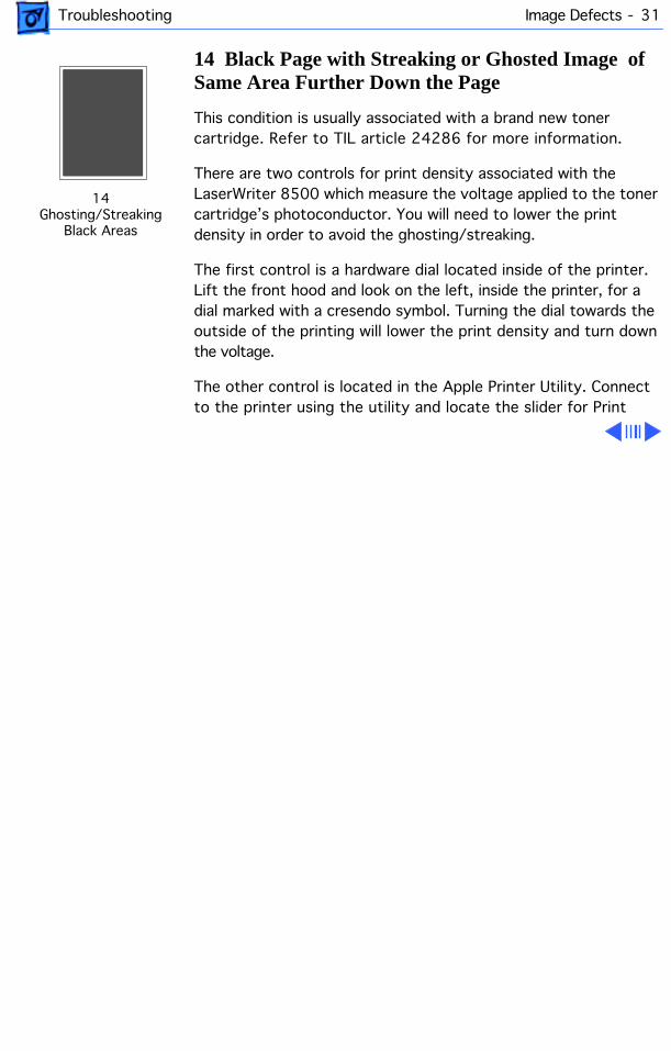
Troubleshooting Image Defects - 31
14 Black Page with Streaking or Ghosted Image of Same Area Further Down the Page
This condition is usually associated with a brand new toner cartridge. Refer to TIL article 24286 for more information.
There are two controls for print density associated with the LaserWriter 8500 which measure the voltage applied to the toner cartridge’s photoconductor. You will need to lower the print density in order to avoid the ghosting/streaking.
The first control is a hardware dial located inside of the printer. Lift the front hood and look on the left, inside the printer, for a dial marked with a cresendo symbol. Turning the dial towards the outside of the printing will lower the print density and turn down the voltage.
The other control is located in the Apple Printer Utility. Connect to the printer using the utility and locate the slider for Print
14Ghosting/Streaking
Black Areas

Troubleshooting Image Defects - 32
Density. Adjust the density down by sliding the control to the left. After adjusting the slider, send the changes to the printer by clicking th Send button at the top of the window.
.
Service Source
K
Exploded View
LaserWriter 8500
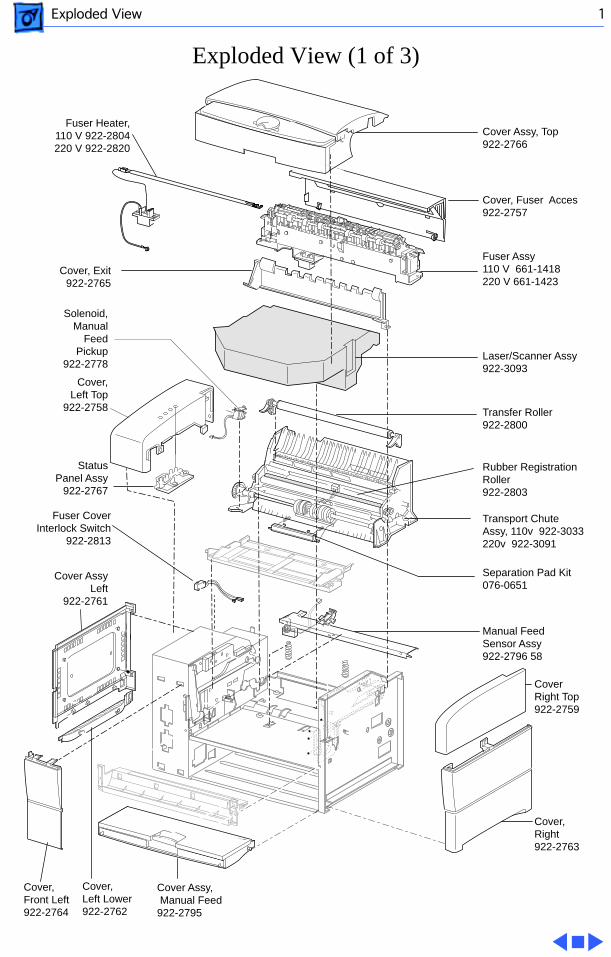
Exploded View 1
Exploded View (1 of 3)
Transport Chute Assy, 110v 922-3033 220v 922-3091
Transfer Roller 922-2800
Separation Pad Kit 076-0651
Fuser Assy 110 V 661-1418220 V 661-1423
Fuser CoverInterlock Switch
922-2813
Cover, Right 922-2763
Cover Right Top 922-2759
Cover, Fuser Acces922-2757
Cover, Exit922-2765
Cover Assy, Manual Feed 922-2795
Cover, Left Lower 922-2762
Cover, Front Left 922-2764
Manual Feed Sensor Assy 922-2796 58
Cover Assy Left
922-2761
Cover Assy, Top922-2766
Cover, Left Top
922-2758
Laser/Scanner Assy 922-3093
StatusPanel Assy
922-2767
Fuser Heater, 110 V 922-2804 220 V 922-2820
Solenoid, Manual
Feed Pickup
922-2778
Rubber RegistrationRoller 922-2803
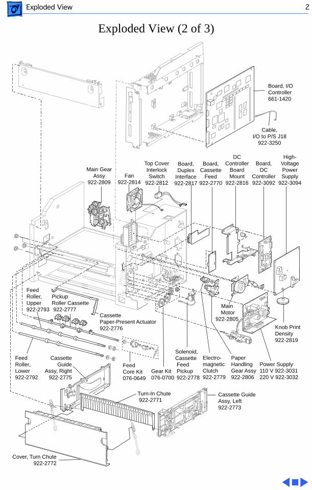
Exploded View 2
Exploded View (2 of 3)
Turn-In Chute 922-2771
Power Supply110 V 922-3031 220 V 922-3032
Knob Print Density 922-2819
High-Voltage Power Supply
922-3094
Cassette Guide Assy, Left922-2773
Cassette Guide
Assy, Right 922-2775
Cassette Paper-Present Actuator 922-2776
Electro-magneticClutch 922-2779
Paper Handling Gear Assy 922-2806
Main Motor
922-2805
DC Controller
Board Mount
922-2816 Fan
922-2814
Board, Duplex
Interface 922-2817
Board, DC
Controller 922-3092
Board, Cassette
Feed 922-2770
Feed Core Kit 076-0649
Feed Roller,Upper 922-2793
Feed Roller,Lower 922-2792
Cover, Turn Chute 922-2772
Gear Kit 076-0700
Top Cover Interlock Switch
922-2812
Main Gear Assy
922-2809
Pickup Roller Cassette 922-2777
Board, I/OController 661-1420
Solenoid, Cassette Feed Pickup 922-2778
Cable, I/O to P/S J18
922-3250
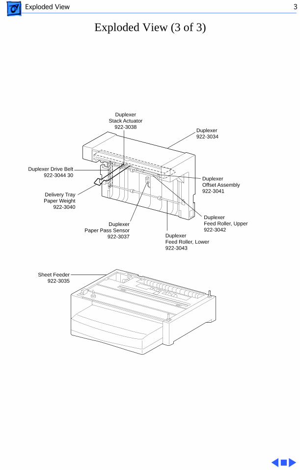
Exploded View 3
Exploded View (3 of 3)
Sheet Feeder 922-3035
Duplexer Paper Pass Sensor
922-3037
Duplexer Offset Assembly922-3041
Duplexer Feed Roller, Upper922-3042
Duplexer Feed Roller, Lower922-3043
Duplexer Drive Belt 922-3044 30
Duplexer Stack Actuator
922-3038Duplexer922-3034
Delivery Tray Paper Weight
922-3040