Embed Size (px)
Citation preview

Appendix
Technical PublicationAP-0015R2
Quick Installation Guidefor TXR Generators
HF Series Generators

HF Series Generators
Appendix -- Quick Installation Guide for TXR Generators
AP-0015R2
REVISION HISTORY
REVISION DATE REASON FOR CHANGE
0 JAN 7, 2004 First edition
1 OCT 16, 2007 General Update & Improvement
2 AGO 06, 2009 Dip--Switch configuration of HT Controller
This Document is the English original version, edited and supplied by the manufacturer.
The Revision state of this Document is indicated in the code number shown at the bottom of this page.
ADVISORY SYMBOLS
The following advisory symbols will be used throughout this manual. Theirapplication and meaning are described below.
DANGERS ADVISE OF CONDITIONS OR SITUATIONS THATIF NOT HEEDED OR AVOIDED WILL CAUSE SERIOUSPERSONAL INJURY OR DEATH.
ADVISE OF CONDITIONS OR SITUATIONS THAT IF NOTHEEDEDORAVOIDEDCOULDCAUSESERIOUSPERSONALINJURY, OR CATASTROPHIC DAMAGE OF EQUIPMENT ORDATA.
Advise of conditions or situations that if not heeded oravoidedcould causepersonal injury or damage to equipmentor data.
Note . Alert readers on pertinent facts and conditions. Notes representinformation that is important to know but which do not necessarilyrelate to possible injury or damage to equipment.

HF Series Generators
Appendix -- Quick Installation Guide for TXR Generators
AP-0015R2 i
TABLE OF CONTENTS
Section Page
1 INSTALLATION 1. . . . . . . . . . . . . . . . . . . . . . . . . . . . . . . . . . . . . . . . . . . . . . . . . . . . . . . . . .
2 CONFIGURATION 9. . . . . . . . . . . . . . . . . . . . . . . . . . . . . . . . . . . . . . . . . . . . . . . . . . . . . . .
2.1 Proper Dip Switch Selections on the ATP Console CPU Board 9. . . . . . . . . . . .
2.2 Configuring the Workstations 10. . . . . . . . . . . . . . . . . . . . . . . . . . . . . . . . . . . . . . . . .
2.3 Configuring the Tube Type 12. . . . . . . . . . . . . . . . . . . . . . . . . . . . . . . . . . . . . . . . . . .
3 CALIBRATION 15. . . . . . . . . . . . . . . . . . . . . . . . . . . . . . . . . . . . . . . . . . . . . . . . . . . . . . . . . .
3.1 Previous Tasks 15. . . . . . . . . . . . . . . . . . . . . . . . . . . . . . . . . . . . . . . . . . . . . . . . . . . . .
3.2 Digital kV Loop Open 16. . . . . . . . . . . . . . . . . . . . . . . . . . . . . . . . . . . . . . . . . . . . . . . .
3.3 Digital mA Loop Closed 17. . . . . . . . . . . . . . . . . . . . . . . . . . . . . . . . . . . . . . . . . . . . . .
3.4 Auto-calibration of Digital mA Loop Open 17. . . . . . . . . . . . . . . . . . . . . . . . . . . . . .
3.5 Final Checks 22. . . . . . . . . . . . . . . . . . . . . . . . . . . . . . . . . . . . . . . . . . . . . . . . . . . . . . .
4 APR EDITING 23. . . . . . . . . . . . . . . . . . . . . . . . . . . . . . . . . . . . . . . . . . . . . . . . . . . . . . . . . . .
5 BUCKYINTERFACECONNECTIONS. . . . . . . . . . . . . . . . . . . . . . . . . . . . . . . . . . . . . . . . . 31

HF Series Generators
Appendix -- Quick Installation Guide for TXR Generators
ii AP-0015R2

HF Series Generators
Appendix -- Quick Installation Guide for TXR Generators
AP-0015R2 1
SECTION 1 INSTALLATION
THISDOCUMENTPROVIDESASTEPBYSTEPGUIDEAND ISNOT INTENDED TO TAKE THE PLACE OF THE SERVICEMANUAL. AS STEPS ARE COMPLETED CHECK OFF THELIST TO THE LEFT OF EACH NUMBER OR PARAGRAPH.
1. Place the Power Module close to its permanent position. For easyinterconnection and calibration place the Generator Cabinet on a tableor pedestal; or mount it to the wall using the Wall Support provided.
2. Verify that wiremarked “:” on Transformer 6T2 terminal strip ismatchedto the incoming power. Identify the Generator type: Single--Phase,Three--Phase or Battery Powered.
POWER SUPPLY LINE FOR SINGLE-PHASE OR BATTERY POWERED GENERATORS
110 VAC orStand-Alone option 208 VAC 220 / 230 VAC 240 VAC
Cable-: in Transformer 6T2 TB-3 or TB-8 TB-21 TB-4 or TB-5 TB-6 or TB-7
POWER SUPPLY LINE FOR THREE-PHASE GENERATORS
220 / 230 / 240 VAC 400 VAC 415 VAC 440 VAC 480 VAC
Cable-: in Transformer 6T2 TB-4 or TB-5 TB-8 TB-7 TB-9 TB-10
6T2 Terminal Strip

HF Series Generators
Appendix -- Quick Installation Guide for TXR Generators
AP-0015R22
3. THIS POINT ONLY APPLIES TO BATTERY POWERED GENERATORS.
a. Open hinged door to access to Charger Module (Mod 1) byremoving the Allen screws.
b. Verify that wire marked “:” is connected to Transformer 2T1terminal strip -- 110 (for 110 VAC).
c. Remove plastic covers over Charger Board and Line MonitorBoard.
d. Plug J1 into the Charger Board, it is unplugged at the factory forsafety.
e. Verify Jumper SW1 connection between SW1--5 and SW1--4(110 VAC).
f. Re-install plastic covers.
6T2 Terminal Strip
Plastic Covers
J1 Connection
T1 Terminal Strip
SW1 Jumper
T1
J1
J1J1
SW1
SW1
Charger BoardLine Monitor Board

HF Series Generators
Appendix -- Quick Installation Guide for TXR Generators
AP-0015R2 3
4. TXR products require 24 VAC for locks. At top of the Generator cabineta 24 VAC Distribution Board has been added to connect these locks.
3 4 5 6 7 8
24 VACDistributionBoard
24VAC 0VAC +24VDC 0VDC +24VDC 0VDC
Terminals 1 and 2 are in coming 24VAC
Collimator is connected to terminals 3 and 4
5. Remove Allen screws that secure hinged door on MOD3 side.

HF Series Generators
Appendix -- Quick Installation Guide for TXR Generators
AP-0015R24
6. The Terminal Strip 4TS2 is located onModule 4 (back ofModule 3) of thehinged door. Connect the X-ray Tube Rotor wiring as follows:
WIRE FROM X-RAY TUBE CONNECTION IN 4TS2
BLACK 4TS2--1
RED 4TS2--2
WHITE 4TS2--3
THERMAL 4TS2--4
THERMAL 4TS2--5
GROUND * 4TS2--6
* If X-ray Tube have not a shielded Ground wire, terminal 4TS2--6 is not used.
4TS2 Terminal Strip
7. Carefully connect the J5 side of the Serial cable to the Console and thenroute the Handswitch wire. Connect the J1 side of the Serial cable fromthe Console to the Generator Cabinet.
Connection of Connection of Serial Cableat Generator Cabinet(located on upper back)
Serial Cableat Console

HF Series Generators
Appendix -- Quick Installation Guide for TXR Generators
AP-0015R2 5
8. Add insulating compound or insulating oil to both High VoltageTransformer receptacles. Connect both High Voltage cables (Anode andCathode) from the X-ray Tube to the HV Transformer receptacles.
9. TheTerminal Strip 3TS1 is locatedonModule 3 (out-sideof hingeddoor).Verify or connect a jumper between terminals 3TS1--22 and 3TS1--23 tobypass the Door Interlock.
Terminal Strip 3TS1
10. THIS POINT ONLY APPLIES TO LINE POWERED GENERATORS.
Remove the plastic cover over the Line Fuses and connect the LinePower cables to the right side of the Fuses at L1 & L2 for Single PhaseGenerators and also at L3 for Three Phase Generators.
Plastic Cover over Line Fuses
L1 Input Line
L2 Input Line
L3 Input Line
Neutral Stud
GND Stud
Input Transf. 6T2
(optional)
Single Phase
Three Phase

HF Series Generators
Appendix -- Quick Installation Guide for TXR Generators
AP-0015R26
11. THIS POINT ONLY APPLIES TO BATTERY POWERED GENERATORS.
a. Connector 6J10 on the right side of Generator Cabinet (Module 6)is unplugged for safety during transport. Plug in it.
Connector 6J10
b. Connect the Line Power cable to Line Connector (wire-1 to left,wire-2 to middle, ground wire to right). These connections arecolor coded.
Line Connector
Circuit Breaker

HF Series Generators
Appendix -- Quick Installation Guide for TXR Generators
AP-0015R2 7
c. TurnOn theCircuit Breaker.Visually check that all green lights andLED DS1 are lit on the Charger Board.
Charger Board
Row of Green LEDs
Connector J1
LED DS1
d. Visually verify that LED DL1 (yellow) is flashing on the LineMonitor Board (2A3). The MAX and MIN LEDs (red) on the LineMonitor Board check the line coming in, neither should be on.
Potentiometer POT1 is factory adjusted. If MAX or MIN LED isON, first check thatMainsVoltage is according to specifications onpage 1 of this guide. If Mains Voltage is correct, adjust POT1 (CWup, CCW lower) measuring between TP-1 and TP-2 on LineMonitor Board. Potentiometer adjustment should be:
Potentiometer = x 2.5Mains Voltage
Nominal Voltage
Potentiometer
Check Light Flashing
Max and Min Lights
Line Monitor Board

HF Series Generators
Appendix -- Quick Installation Guide for TXR Generators
AP-0015R28
This page intentionally left blank.

HF Series Generators
Appendix -- Quick Installation Guide for TXR Generators
AP-0015R2 9
SECTION 2 CONFIGURATION
2.1 PROPER DIP SWITCH SELECTIONS ON THE ATP CONSOLE CPU BOARD
The ATP Console CPU Board is located on Module 4 side of theHinged Door.
1. Locate Switches #1, #2 and #3 on the ATPConsole CPUBoard from theillustration.
G Switch #1 contains four Dip Switches.
G Switch #2 contains four Dip Switches.
G Switch #3 contains eight Dip Switches (for factory use).
ATP Console Board Swicth #1
Swicth #2
Swicth #3
2. Configuration of Switch #1.
G For use with 60 Hertz Line Supply: All four Dip Switches mustbe placed in the down (OFF) position.
G For use with 50 Hertz Line Supply: The first Dip Switch must beplaced in the up (ON) position. The second, third and fourth DipSwitches must be placed in the down (OFF) position.
3. Configuration of Switch #2. The first, third and fourth Dip Switchesmust be placed in the up (ON) position. The second Dip Switch must beplaced in the down (OFF) position.
4. Configuration of Switch #3. All eight Dip Switches must be placed inthe down (OFF) position.
Note .

HF Series Generators
Appendix -- Quick Installation Guide for TXR Generators
AP-0015R210
2.2 CONFIGURING THE WORKSTATIONS
1. With the Generator OFF, make sure Dip 3 of Switch #2 on the ATPConsoleCPUBoard (Module 4 side) is placed in the closed (ON) position(Service Mode enabled).
2. Turn ON the Line Power and then the Console power. Wait for the selftesting to finish, then enter in configurationmode bymaintaining pressedPower ON, “200” and “800” simultaneously for at least two seconds untilall of the workstations push-buttons are illuminated.
3. Results you should see:
A display of numbers will be visible on the kVp, mAs, mA and timedisplays. The visible numbers will either be 0, 1, 2, etc.
The Console is equipped to operate in five different modes(workstations). The three push-buttons at the upper-left provide a way toprogram for different operations. See the following tables for properselections.

HF Series Generators
Appendix -- Quick Installation Guide for TXR Generators
AP-0015R2 11
4. Select the firstworkstation to beconfigured (Bucky1,Bucky2,NoBucky)by pressing the respective push-button, only this push-button blinks andthe console shows one of the following values:
DISPLAY FUNCTION VALUE DESCRIPTION
0 No-configured workstation
1st Value SELECT THE TUBE 1 Tube-1
2 Tube-2
0 Direct (No Bucky)
1 Bucky-1
2nd Value SELECT THE DEVICE(WORKING MODE)
2 Bucky-2(WORKING MODE)
3 Standard Tomo *1)
4 Standard RF
0 No AEC
1 Ion Chamber-1
3rd ValueSELECT THE IONCHAMBERS BEING
USED (ONLY WITH AEC)2 Ion Chamber-2
USED (ONLY WITH AEC)3 Ion Chamber-3
4 Ion Chamber-4
Notes.-- Some values may not be configurable, depending on Generator model.*1) Only when the Tomo is controlled by the Generator.
5. Set the new value by pressing the Density “+” or “--” buttons located atthe bottom left corner of theOperatorConsole.When the first value is “0”,the second and third value are “0”.
The following table is an example of a 2 tube System with 2 Buckys andno Ion Chambers.
B tt kV A A TiButton kVp mAs mA Time
Bucky 11
(tube 1)1
(Bucky 1)0
(no Ion Chamber)0
Bucky 22
(tube 2)2
(Bucky 2)0
(no Ion Chamber)0
No Bucky1
(tube 1)0
(No Bucky)0
(no Ion Chamber)0
HF Series Generators
Appendix -- Quick Installation Guide for TXR Generators
AP-0015R212
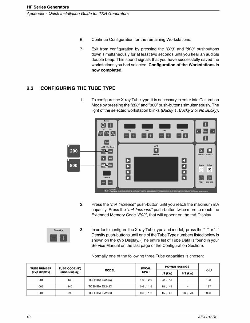
6. Continue Configuration for the remaining Workstations.
7. Exit from configuration by pressing the “200” and “800” pushbuttonsdown simultaneously for at least two seconds until you hear an audibledouble beep. This sound signals that you have successfully saved theworkstations you had selected. Configuration of the Workstations isnow completed.
2.3 CONFIGURING THE TUBE TYPE
1. To configure the X-ray Tube type, it is necessary to enter into CalibrationMode by pressing the “200” and “800” push-buttons simultaneously. Thelight of the selected workstation blinks (Bucky 1, Bucky 2 or No Bucky).
2. Press the “mA Increase” push-button until you reach the maximum mAcapacity. Press the “mA Increase” push-button twice more to reach theExtended Memory Code “E02”, that will appear on the mA Display.
3. In order to configure the X-ray Tube type and model, press the “+” or “--”Density push-buttons until one of the Tube Type numbers listed below isshown on the kVp Display. (The entire list of Tube Data is found in yourService Manual on the last page of the Configuration Section).
Normally one of the following three Tube capacities is chosen:
TUBE NUMBER TUBE CODE (ID)MODEL
FOCAL POWER RATINGSKHU
TUBE NUMBER(kVp Display)
TUBE CODE (ID)(mAs Display) MODEL
FOCALSPOT LS (kW) HS (kW)
KHU
001 139 TOSHIBA E7239X 1.0 / 2.0 22 / 45 -- 133
003 140 TOSHIBA E7242X 0.6 / 1.5 18 / 49 -- 187
004 090 TOSHIBA E7252X 0.6 / 1.2 15 / 42 26 / 73 300

HF Series Generators
Appendix -- Quick Installation Guide for TXR Generators
AP-0015R2 13
4. Verify that the Tube code (ID) shown on the mAs Display is the same asthe tube code listed in the table above or in the Tube Table of the ServiceManual.
5. Press the “Reset” Push-button to save and permanently store the X-rayTube configuration. You will once again hear an audible beep to confirmthat you have successfully saved your selection.
At this point, if your selected Bucky is still blinking, you are alreadyin Service Mode and ready for Autocalibration. If your selectedBucky is not blinking, press “200” and “800” simultaneously for atleast two seconds to enter Service Mode.
Note .

HF Series Generators
Appendix -- Quick Installation Guide for TXR Generators
AP-0015R214
This page intentionally left blank.

HF Series Generators
Appendix -- Quick Installation Guide for TXR Generators
AP-0015R2 15
SECTION 3 CALIBRATION
3.1 PREVIOUS TASKS
Before calibration, keep in mind that:
1. To calibrate and measure the kVp output, a Non-Invasive kVp Meter isneeded.
Place and center a Non-Invasive kVp Meter on the X-ray Tube output atthe required SID (refer to the Non-Invasive kVp Meter documentation).
2. To calibrate and measure the mA or mAs, a mAs Meter needs to beplugged to the banana plug connection at the top of the HV Transformer.
The cross bar (link plate) should not be connecting thebanana plug. Turn the Generator OFF to connect the mAsmeter if you did not connect one at the beginning.
Remember to re-install the cross bar between the bananaplug connections after removing the mAs meter.
Remove the cross bar (link)and plug the mAs meter here.

HF Series Generators
Appendix -- Quick Installation Guide for TXR Generators
AP-0015R216
3. Before calibration procedure, verify that the Dip Switches of Switch #2 oftheHTController Board (A3000--xx) are in the “OFF” position. This boardis located on Module 3 at the hinged door.
Switch #2 on theHT Controller Board
3.2 DIGITAL KV LOOP OPEN
Extended Memory Location E06 contains the calibration factor for Digital kVLoop Open.
TheValue inE06Memory Location is only related to theGeneratorperformance (it is not related to the X-ray Tube(s) or anothercomponents installed), this Memory Location is factoryadjusted. Only perform this procedure if the HT Controller Boardand/or HV Transformer have been replaced in the unit. For that,refer to the Service Manual -- Calibration Chapter.
Note .

HF Series Generators
Appendix -- Quick Installation Guide for TXR Generators
AP-0015R2 17
3.3 DIGITAL mA LOOP CLOSED
Extended Memory Locations E03 and E05 contain the calibration factor forDigital mA Loop Closed.
Values in E03 and E05 Memory Locations are only related to theGenerator performance (they are not related to the X-ray Tube(s)installed).TheseMemoryLocationsare factoryadjusted. Onlyperform this procedure if the HT Controller Board and/or HVTransformer have been replaced in the unit. For that, refer to theService Manual -- Calibration Chapter.
3.4 AUTO-CALIBRATION OF DIGITAL mA LOOP OPEN
To achieve the most accurate calibration, this procedure has to beautomatically performed by the Generator (Auto-calibration).
The Calibration procedure should be manually performed only ifAuto-calibration is not possible. In this case, refer to the Service Manual(Calibration Chapter -- Section “Manual Calibration of Digital mA Loop Open”).
Auto-calibration of the Filament Current Numbers is divided in two separatedprocedures related to the mA stations configured for the Small or Large FocalSpots. Start with the Small Focal Spot (first group) and continue with the LargeFocal Spot (second group).
EACH TIME THAT AUTO-CALIBRATION IS ACTIVATED IN AmA STATION (OR IN “E01” MEMORY LOCATION), ALL THEFILAMENTCURRENTNUMBERSOFTHESELECTEDFOCALSPOT ARE AUTOMATICALLY SET TO “344”. SO A NEWCOMPLETE CALIBRATION OF THE FILAMENT CURRENTNUMBERS FOR THIS FOCAL SPOT WILL BE REQUIRED.
Note .

HF Series Generators
Appendix -- Quick Installation Guide for TXR Generators
AP-0015R218
Auto-calibration starts with the minimum available mA station for theselected Focal Spot at 50 kV and follows with the other combinations ofmA stations for the selected Focal Spot at 80 kV, 120 kV and 40 kV.
1. For this procedure, set Dip Switch 4 of Switch #2 on the HT ControllerBoard back in the “ON” position (Digital mA Loop Open / FilamentCurrent Constant).
1. Select the “No Bucky” workstation (Direct).
2. Enter calibration mode by pressing the “200” and “800” push-buttonssimultaneously and select one of the configured mA stations for theSmall Focal Spot (Light will be blinking for workstation selected if youare in Service Mode).
HF Series Generators
Appendix -- Quick Installation Guide for TXR Generators
AP-0015R2 19
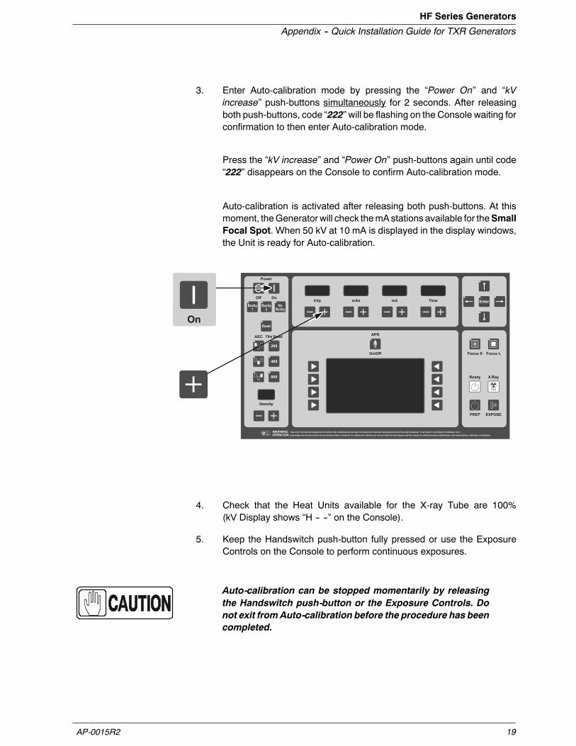
3. Enter Auto-calibration mode by pressing the “Power On” and “kVincrease” push-buttons simultaneously for 2 seconds. After releasingboth push-buttons, code “222” will be flashing on the Console waiting forconfirmation to then enter Auto-calibration mode.
Press the “kV increase” and “Power On” push-buttons again until code“222” disappears on the Console to confirm Auto-calibration mode.
Auto-calibration is activated after releasing both push-buttons. At thismoment, theGenerator will check themAstations available for theSmallFocal Spot. When 50 kV at 10 mA is displayed in the display windows,the Unit is ready for Auto-calibration.
4. Check that the Heat Units available for the X-ray Tube are 100%(kV Display shows “H -- --” on the Console).
5. Keep the Handswitch push-button fully pressed or use the ExposureControls on the Console to perform continuous exposures.
Auto-calibration can be stopped momentarily by releasingthe Handswitch push-button or the Exposure Controls. Donot exit fromAuto-calibration before the procedure has beencompleted.

HF Series Generators
Appendix -- Quick Installation Guide for TXR Generators
AP-0015R220
If the Heat Units available for the X-ray Tube are less than 40%,exposuresare inhibitedmomentarily andcode “111”will be flashedon theConsole accompanied by an alarm. In this case, release theHandswitchor Exposure Controls to stop momentarily the Auto-calibrationprocedure. The alarm will stop when the X-ray Tube begins to cool andrecovers the Heat Units capacity. Exposures can be performed againeven though code “111” is shown on the Console.
At this point, it is recommended to wait until the Heat Units available areclose to 80% of the X-ray Tube capacity without making any exposure.
The Generator will try to calibrate each kV / mA combination for ten (10)attempts (maximum). If calibration is aborted (after ten attempts), code“888” will flash on the Console until the “Power On” push-button ispressed to exit Calibration. Calibration might also abort due to spacecharge during calibration of the lowest kV at the highest mA stations forthe Focal Spot selected, so code “777” will be flashing on the Consoleuntil the “Power On” push-button is pressed.
IF AUTO-CALIBRATION IS ABORTED (CODE “888” OR“777”), CONTINUE AUTO-CALIBRATION FOR THE OTHERFOCAL SPOT. CHECK AT THE END OF AUTO-CALIBRATIONWHICH KV / MA COMBINATIONS HAVE NOT BEENAUTO-CALIBRATED FOR EACH FOCAL SPOT (THESECOMBINATIONS HAVE THE FILAMENT CURRENT NUMBERSET TO “344”). MANUALLY CALIBRATE THESE KV / MACOMBINATIONS AS EXPLAINED IN THE SERVICE MANUAL(CALIBRATION CHAPTER -- “MANUAL CALIBRATION OFDIGITAL mA LOOP OPEN”).
When Auto-calibration is successfully performed, code “999” will beflashing on the Console until press the “Power On” push-button for 2seconds to exit from Auto-calibration mode. The “999” code willdisappear when you have successfully exited Calibration.
6. To calibrate the Large Focal Spot, select one of the configured mAstations for the Large Focal Spot by pressing the mA “+” push-button.Repeat steps 2.-- 5.
Before starting the exposures, it is recommended to wait until the HeatUnits available are closed to the 80% of the X-ray Tube capacity.

HF Series Generators
Appendix -- Quick Installation Guide for TXR Generators
AP-0015R2 21
7. After performing both procedures (for Small and Large Focal Spots),select in calibrationmode each combination of the available mA stationsat the kV break points (40, 50, 80 and 120 kV). Press the “Reset”push-button to read on the kV Display the new value of the FilamentCurrent Number stored for each combination and write down the newvalues in the Data Book.
Note that the highestmA station for Small Focal Spotmay have numberslarger than the lowest mA station for Large Focal Spot. This is normal.
8. Repeat the above calibration process for the second tube.
9. Exit calibration mode.
10. SetDipSwitch 4of Switch #2on theHT Controller Boardback in the“OFF” position (Digital mA Loop Closed).
Table 3-1mA Calibration Numbers
mA STATIONFILAMENT CURRENT NUMBERS AT kV BREAK POINT
mA STATION40 50 80 120
10
12.5
16
20
25
32
40
50
64
80
100
125
160
200
250
320
400
500
640
800
Note.-- Some Generator models do not contain all the mA stations listed above.

HF Series Generators
Appendix -- Quick Installation Guide for TXR Generators
AP-0015R222
3.5 FINAL CHECKS
Verify that all Configuration and Calibration data have been properly stored inmemory.
1. Enter in calibration mode and check that the values noted for the“Filament Current Numbers” and “Extended Memory Locations” of theData Book are the same values displayed and stored in memory. Pressthe “Reset” button to read the stored values.
2. Exit from calibration mode and Service mode.
3. Turn the Generator OFF and verify position of Dip Switches of Switch #2on the HT Controller Board are:
G Dip Switch 2 in “Off” position (enables Filament and RotorInterlocks).
G Dip Switch 4 in “Off” position (Digital mA Loop Closed).
4. Set Dip Switch 3 of Switch #2 on the ATP Console CPU Board in “Off”position to place the Generator in normal operating mode.

HF Series Generators
Appendix -- Quick Installation Guide for TXR Generators
AP-0015R2 23
SECTION 4 APR EDITING
Any APR Technique may be modified to fit the operator requirements. It ispossible to change and store in memory the names (Body Region / AnatomicalView / Projection), SID, Thickness value (range and default value), selections(Workstation and AEC) and radiographic parameters related to selectedThickness value.
Creating orDeleting anBodyRegion,Anatomical View,Projectionand Thickness can only be performed from the PC APR Editor.(Refer to Section 4 of the Operating Manual).
Proceed in the following way:
1. With the APR deactivated, press simultaneously “APR ON/OFF” and“Enter” buttons. All the LEDs of the Edition Module buttons lights up.
REGION3 REGION4
REGION5 REGION6 REGION7 REGION8
REGION2
ENTER REGION
Edition Module with “Edit-Arrow”buttons and “Enter” button
REGION1
Display Selector
The EditionModule is operated with the “Edit-Arrow” buttons, the “Enter”button and the Display Selectors.
Press the “Edit-Arrow” buttons to scroll in the APR Display. Whenpressing the Display Selector on the left lower corner, the APR Displaywill showsequentially the selectedRegion /View /Projectionat theupperline.
Note .
Enter+

HF Series Generators
Appendix -- Quick Installation Guide for TXR Generators
AP-0015R224
2. Body Region. Once the desired Body Region (highlighted) is chosenwith the “Edit-Arrow” buttons, if the operator requires to modify theRegion name, go to step 3. If not, press the Display Selector close to“ENTER REGION” to go to step 4.
REGION1 REGION3 REGION4
REGION5 REGION6 REGION7 REGION8
REGION2
ENTER REGION
Enter Selection andgo to next screen
3. Modify theRegion name. Press “Enter” to edit the name of the selectedRegion. The first letter of the name is highlighted, the “Up/DownEdit-Arrow” buttons will change the letter in alphanumerical order (plusunderscore and blank), the “Right/Left Edit-Arrow” buttons will scroll intheword.Once the name iswritten, press “Enter” to save the newRegionname. If necessary, repeat this process to rename other Regions.
REGION1 REGION3 REGION4
REGION5 REGION6 REGION7 REGION8
REGION2
ENTER REGION
EGION1R
Enter Selection andgo to next screen
Edit name
Press the Display Selector close to “ENTER REGION” to go to step 4.

HF Series Generators
Appendix -- Quick Installation Guide for TXR Generators
AP-0015R2 25
4. Anatomical View. Once the desired Anatomical View (highlighted) ischosen with the “Edit-Arrow” buttons, if the operator requires to modifythe View name, go to step 5. If not, press the Display Selector close to“ENTER VIEW” to go to step 6.; or “BACK” to return to the previousscreen.
VIEW2 VIEW3 VIEW4
VIEW5 VIEW6 VIEW7 VIEW8
REGION1
ENTER VIEW
VIEW1
BACK
Enter Selection andgo to next screen Go to previous screen
5. Modify the View name. Press “Enter” to edit the name of the selectedView. The first letter of the name is highlighted, the “Up/DownEdit-Arrow”buttons will change the letter in alphanumerical order (plus underscoreand blank), the “Right/Left Edit-Arrow” buttons will scroll in the word.Once the name is written, press “Enter” to save the new View name. Ifnecessary, repeat this process to rename other Views.
VIEW1 VIEW2 VIEW4
VIEW5 VIEW6 VIEW7 VIEW8
REGION1
ENTER VIEW
VIEW3
3VIEW
CANCEL
Cancel and go toprevious screen
Edit nameEnter Selection andgo to next screen
Press the Display Selector close to “CANCEL” to go back to previousscreen without saving the changes or press the Display Selector closeto “ENTER VIEW” to go to step 6.

HF Series Generators
Appendix -- Quick Installation Guide for TXR Generators
AP-0015R226
6. Projection. Once the desired Projection (highlighted) is chosenwith the“Edit-Arrow” buttons, if the operator requires to modify the Projection, goto step 7. If not, press the Display Selector close to “ENTERPROJECTION” to go to step 8. or “BACK” to return to the previousscreen.
VIEW3REGION1
ENTER PROJECTION
PROJECT1
BACK
PROJECT2
PROJECT4
PROJECT3
PROJECT5Enter Selection andgo to next screen Go to previous screen
7. Modify the Projection name. Press “Enter” to edit the name of theselected Projection. The first letter of the name is highlighted, the“Up/Down Edit-Arrow” buttons will change the letter in alphanumericalorder (plus underscore and blank), the “Right/Left Edit-Arrow” buttonswill scroll in the word. Once the name is written, press “Enter” to save thenew Projection name. If necessary, repeat this process to rename otherProjections.
VIEW3REGION1
ENTER PROJECTION
PROJECT1
CANCEL
PROJECT2
PROJECT4
PROJECT3
PROJECT5
1PROJECT
Edit name
Cancel and go toprevious screen
Enter Selection andgo to next screen
Press the Display Selector close to “CANCEL” to go back to previousscreen without saving the changes or press the Display Selector closeto “ENTER PROJECTION” to go to step 8.

HF Series Generators
Appendix -- Quick Installation Guide for TXR Generators
AP-0015R2 27
8. Once the Display Selector close to “ENTER PROJECTION” has beenpressed, the APR Display shows:
G The name of the Region/View/Projection (upper line).
G The Thickness values for Minimum Thickness, Default Thicknessand Thickness Step that might be applied to the selected Region /View / Projection.
If required, these Thickness values can be edited as described below:
MINIMUM THICKNESS: 3 cm
DEFAULT THICKNESS: 5 cm
REGION1
ENTER TECHNIQUE
VIEW3
BACK
PROJECT1
THICKNESS STEP: 2 cm
Enter Selection andgo to next screen Go to previous screen
9. Modify the Minimum Thickness, the Default Thickness or theThickness Step. If the operator decides to modify a Thickness value,follow this step, if not, go to next step.
Press the “Edit-Arrow” button to highlight the corresponding line andpress “Enter” button to modify the selected Thickness.
“MT:__” (minimum), “DT:__” (default) or “TS:__” (thickness step)appearsat the right corner of the Display, then select the desired number with the“Edit-Arrow” buttons and press “Enter” to save the changes and go backto previous screen, or press the Display Selector close to “CANCEL” togo back to previous screen without saving the changes.
REGION1 VIEW3
CANCEL
MT:_ 3PROJECT1
MINIMUM THICKNESS: 3 cm
DEFAULT THICKNESS: 5 cm
THICKNESS STEP: 2 cm
EditThickness
Cancel and go toprevious screen

HF Series Generators
Appendix -- Quick Installation Guide for TXR Generators
AP-0015R228
MinimumThickness (MT__) sets theminimumvalue in centimeters usedfor the selected Region/View/Projection.
Default Thickness (DT__) sets thedefault value in centimeters accordingto the operator preferences.
Thickness Step (TS__) sets the number of centimeters between eachthickness value. Each Region/View/Projection may have a maximum oftwenty (20) Steps.
Themaximum range for a Thickness value is 99 cm, whichmeansthat a Minimum Thickness value too high or a Thickness Step toolarge will not be allowed if the resulting value is over 99 cm.
Calculate if the Thickness values are allowed by applying the formula:(MT + 19) x TS
where:MT = Minimum Thickness19 = Maximum number of Steps minus oneTS = Thickness Step value
For example, in the figure below, the formula is (3+19) x 2 = 44 cm.Inwhich “3” is theMinimumThickness, “19” is thenumberofSteps (20--1)and “2” is the Thickness Step value. “44” is the resulting maximumThickness but if the Thickness Step value is 8, it would not be allowedas the range is over 99 cm: (3+19) x 8 = 168 cm.
MINIMUM THICKNESS: 3 cm
DEFAULT THICKNESS: 5 cm
REGION1
ENTER TECHNIQUE
VIEW3
BACK
PROJECT1
THICKNESS STEP: 2 cm
Note .

HF Series Generators
Appendix -- Quick Installation Guide for TXR Generators
AP-0015R2 29
10. Modify the Radiographic Technique Values. In order to modify theRadiographic Technique values for a specific Region/View/Projection,press the Display Selector close to “ENTER TECHNIQUE”.
MINIMUM THICKNESS: 3 cm
DEFAULT THICKNESS: 5 cm
REGION1
ENTER TECHNIQUE
VIEW3
BACK
PROJECT1
THICKNESS STEP: 2 cm
Enter Selection andgo to next screen Go to previous screen
The Display will show the Region, View, Projection and the DefaultThickness (highlighted) for the selected Region/View/Projection. Press“Enter” to edit the APR technique for the displayed Thickness, orbefore pressing “Enter” modify the Thickness with the “Up/DownEdit-Arrows” if the APR technique to bemodified corresponds to anotherThickness value.
CANCEL
THCK: 3 cm
EnterREGION1 VIEW3 PROJECT1
Cancel and go toprevious screen
ChangeThickness value
After pressing “Enter”, the Console automatically displays all theradiographic parameters (kVp,mA,mAs, Time), selections (Workstationand AEC) and SID indication related to that Region/View/Projection.
Now, the operator can modify and store the Radiographic Parameters,Workstation, AEC Selections and SID indication (36”, 40”, 60” or 72”selected with the “Up/down Edit-Arrows”).

HF Series Generators
Appendix -- Quick Installation Guide for TXR Generators
AP-0015R230
Keep inmind that all Thickness values of aProjectionwill share the sameAEC values, Workstations and SID, that means that if one of theseParameters is modified, it will affect to all Thickness values for thatspecific Region - View - Projection.
EDIT REGIONX VIEWZ
CANCEL
THCK 7
125 80.0 250 .320
2
REGION1 VIEW3
CANCEL
SID 40”
THCK:3PROJECT1
AEC, Workstations and SID are common values for all Thickness in a Projection.
If an APR technique is to be stored with AEC parameters, asuitable back-up time (and/or mAs) MUST be stored in theprogram by the operator.
11. Press “Enter” to save in memory the new parameters and selectionsassigned to the selected Region/View/Project and Thickness value.
12. Press simultaneously “APRON/OFF”and “Enter”buttons to exit from theAPR edition mode.
Note .

Technical Pamphlet W-2009-7-20 1
3

Technical Pamphlet W-2009-7-20 2
3Technical Pamphlet W-2009-7-20 2
3Technical Pamphlet W-2009-7-20 2
3
Technical Pamphlet W-2009-7-20 3
3

Technical Pamphlet W-2009-7-20 4
3Technical Pamphlet W-2009-7-20 4
3 Technical Pamphlet W-2009-7-20 4
3


