Embed Size (px)
Citation preview

APPENDIX D
REPORT OF DESIGN PANEL

.--...

CONTENTS
Part
APPENDIX D - REPORT OF DESIGN PANEL
Dl TASKASSIGNMENT ...................
D2 PANEL ORGANIZATION .................
D3 REVIEWANDANALYSIS .................
SYSTEM DESCRIPTION ................
ELECTRICAL SYSTEM CONFIGURATION AT TIME OFACCIDENT...................
STRUCTURAL EVALUATION OF THE OXYGEN TANK . . . . .
Materials and Welding . . . . . . . . . . . . , .
Qualification Program . . . . . . . . . . . . . .
FRACTUREMECHANICS . . . . . . . . . . . . . . . .
Failure Modes . . . . . . . . . . . . . . . . . .
Effectiveness of the Proof Test . . . . . . . . .
Possibility of Tank Failure During Apollo 13 Mission....................
DYNAMIC TESTING. . . . . . . . . . . . . . . . . .
Oxygen Tank Assembly Dynamic Testing . . . , , .
Apollo CSM Acoustic and Vibration Test Program.. , . . . . . . . . . . . . . . . . .
SHOCK TESTING . . . . . . . . . . . . . . , . . . .
INTERNAL COMPONENTS. . . . . . . . . . . , . . . .
QuantityGage..................
Heaters....,........,,......
iii
Pa@;e
D-l
D-3
D-5
D-5
D-11
D-13
D-13
D-20
D-23
~-24
D-25
D-30
D-30
D-30
D-31
D-35
D-35
D-35
D-37
Part
Fans . . . . . . . . . . . . . . . . . . . . . .
Temperature Sensor . . . . . . . . - . . . - . .
Wiring .....................
Discussion ...................
COMPATIBILITY OF MATERIALS WITH OXYGEN ......
Classification Methods . . . . . . . . . . . . .
Materials Internal to the Tank .........
OTHER DESIGN AND SYSTEM CONSIDERATIONS ......
Oxygen System Relief Valves ...........
Arrangement at Head of Tank . . . . . . . . . . .
Dome Assembly ..................
Filter .....................
Caution and Warning Provisions .........
ABNORMAL EVENTS IN THE HISTORY OF THE OXYGEN TANK ......................
Oxygen "Shelf Drop" Incident ..........
DetankingatKSC ................
Discussion ...................
RELATED SYSTEMS. .................
Pressure Vessels ................
Line Components . . . . . . . . . . . . . . . . .
Low Pressure Oxygen Systems ...........
Electrical Power System--Batteries .......
iv
Page
D-41
D-43
D-43
~-48
~-48
D-49
D-49
D-59
D-59
D-61
~-64
D-70
D-70 '
D-71
D-71
D-72
D-74
D-78
D-78
D-85
D-86
D-86

Part
D4
D5
Page
Ground Support Equipment ............ D-86
Certification .................. D-87
Apollo J-Missions ................ D-87
Lunar Module "Lifeboat" ............. D-87
DISCUSSION .................... D-87
SUMMARY ....................... D-89
REFERENCES ..................... D-93

This page left blank intentionally.
vi
._I .,-. l.-..~--l.---l --._ - ,.““x_... .” _x._i . . . . ...” ---. -.^_- -... _.___-9_-_-~11_- --_--n ..,,. .- ~----

PART Dl
TASK ASSIGNMFJW
The Design Panel was assigned the task of reviewing the design of the systems involved in the Apollo 13 accident, including their qualifi- cation history. The service history of the specific components flown on Apollo 13 was also to be examined from a design point of view to as- certain whether any abnormal usage experienced might have had a detri- mental effect on the functional integrity of the components. The Panel was also charged with review of other spacecraft systems of similar de- sign or function to ascertain whether they contained potential hazards. Finally, the Panel was to analyze, as required by the Board, proposed failure mechanisms to the extent necessary to support the theory of failure.
The Panel conducted its activities by reviewing design documentation and drawings, historical records, and test reports; analyzing data; ex- amining specimens of hardware; and consulting with other Board Panels and with members of the Manned Spacecraft Center (MSC) Investigation Team and the contractors.
D-1
This page left blank intentionalu.
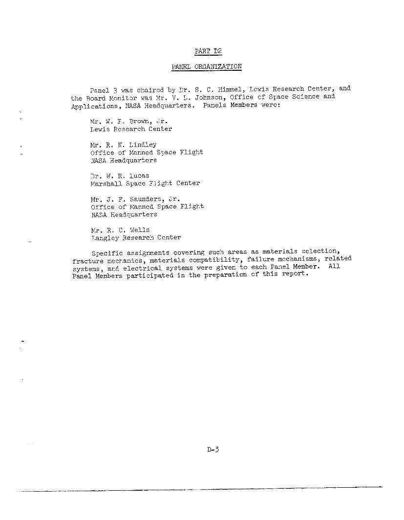
PART D2
PANEL ORGANIZATION
Panel 3 was chaired by Dr. S. C. Himmel, Lewis Research Center, and the Board Monitor was Mr. V. L. Johnson, Office of Space Science and Applications, NASA Headquarters. Panels Members were:
Mr. W. F. Brown, Jr. Lewis Research Center
Mr. R. N. Lindley Office of Manned Space Flight NASA Headquarters
Dr. W. R. Lucas Marshall Space Flight Center
Mr. J. F. Saunders, Jr. Office of Manned Space Flight NASA Headquarters
Mr. R. C. Wells Langley Research Center
Specific assignments covering such areas as materials selection, fracture mechanics, materials compatibility, failure mechanisms, related systems, and electrical systems were given to each Panel Member. All
Panel Members participated in the preparation of this report.
D-3
-,- ._ .-.. _-

This page left blank intentionally.
D-4
.l. , . -_ , - _ . -_~ - . . - “ . - I - . _ _ ._. . . “_ - - . . “ . . ^“~L1. _^_,_*._.--_.-- . _ . . - . . . . - __- - - . . . .~ _ “__c.._. ; - , _ , _*ZI._-i . - . - - - -

PART D3
REVIEW AND ANALYSIS
Early in the proceedings of the Board, it became evident that the failure was centered in the cryogenic oxygen subsystem of the electrical power system of the spacecraft, and, more specifically, in the no. 2 cryogenic oxygen tank. For this reason, detailed examinations of the Panel were limited to this subsystem. Interfacing systems were examined only to the extent required to understand the function of the oxygen system and/or to relate data from flight or test to the operation or design of the system.
In addition, the Panel had one of its members present at the deliberations of the MSC Panel on Related Systems which conducted reviews on other Apollo spacecraft pressurized systems.
SYSTEM DESCRIPTION
-,
The cryogenic storage subsystem supplies reactants to the fuel cells that provide electric power for the spacecraft. The oxygen system also supplies metabolic oxygen for the crew, command module (CM) cabin pressur- ization, and the initial pressurization of the lunar module (LM). The cryogenic storage and fuel cell subsystems are located in bay 4 of the service module (SM). Figure D3-1 shows the geometric arrangement of these subsystems within this portion of the SM. The system comprises two oxygen tanks, two hydrogen tanks, and three fuel cells with their associated plumbing, control valves, regulators, pressure switches, and instrumentation.
The uppermost shelf contains the three fuel cells; the center shelf contains the two oxygen tanks, the oxygen system valve modules, the fuel cell oxygen valve module, and a ground service interface panel. The lower shelf contains the two hydrogen tanks, one above and one below the shelf, and a set of valve modules analagous in function to those of the oxygen system.
A description of these components is contained in Appendix A of the Board's report. Also provided are the operating and design parameters of the components, materials of construction, etc.
A schematic of the oxygen system is shown in figure D3-2. The ground service lines are capped off prior to flight. Figure D3-3 is a photograph of the panel showing the terminations of these lines. The two tanks and
D-5

\ cell
2
Oxygen valve module
Oxygen fuel cell shut off valve module
Oxygen servicing panel
C-Hydrogen
Figure D3-l.- Arrangement of fuel cells and cryogenic systems in bay 4.
D-6
. _ --- ._...--- l.“-.l .____ _.^._.__I_ .L^. -~-.. “. .l.-.-“--r ._“._ .._.” .-.-- ~-- .._~ _.----_ -1.4.. -.-.I---.-lll-l-

Pressure Pressure
- 1 Fill line switch transducer
T 114x .015x 14
r1/4X.O2OX38 QQ 5 PT
dis- I II -1 connects !
I
Ground 1 Service support facility I
module
1
lnterlor Interface
I I?:,, ..^..1 ,:..a -
@I I
314x.028x45.0 A
* I nconel X line H Relief valve t
coiled within 114X&20X 83 n
-4 Fuel cell 3 1
insulating space 1/4X.020X16
,119” .015x 115
1 Insulation
Vent line 1 3/8x:020x32.5 -
Vent line 1 114x .020x 12
r -114x .015x 14 ( )r Relief valve
1/4x.020x37.5
II II- c ; ‘:1
L’ J
114 X .020 X 81.9
ross
L 114x .020x 11
C
1 Figure D3-2.- Oxygen system.
// Ground ‘Service support I module facility 1 interior ~nlerfacel
/
Insulation
Note: All external lines are 304 low carbon stainless steel.
All dimensions are in inches.
Dimensions are: Outside diameter xwall thicknessxline length
Cap t Purge line
c 1 318x.020

Figure D3-3.- SM OWESen system ground service panel.
D-8
I --_..- -._ -.-- 11-1 .. -- -----'^ ___- ,__..e _.. _.,,. I _-_- -..
- _ ~.__.. .._" _._ __...-. ."-.-- -_"._. _- ---
their plumbing are identical except for one point in the feed line from tank no. 2, at which a ground service line tees into the feed line down- stream of a check valve. This ground service line permits the operation of the fuel cells and the environmental control system (EC'S) oxygen system from a ground source of oxygen without requiring the use of the flight tankage. This line terminates at the fitting designated OP in figure D3-3. The check valve prevents the pressurization of tank no. 2 from this ground source .
The pressure transducer, pressure switch, and relief valve are lo- cated in an oxygen system valve module external to the tank. A photograph of the module is shown in figure D3-4. 'Two of each of these components plus the check valve for tank no. 2 referred to in the previous paragraph comprise the module. Figure D3-4 shows the top of the oxygen shelf. There are approximately 19 feet of feed line from the tank pressure vessel to the valve module.
The feed line exits the oxygen system valve module and branches, one going to the ECS and the other to the fuel cell valve module where the lines from tanks no. 1 and no. 2 are manifolded within the body of this assembly. This module contains the check valves at the feed line entrance points and three solenoid shutoff valves, one for each of the fuel cells.
The cryogenic ovgen electrical system consists of the following items for each tank:
1. Two electrical heaters, rated at 77.5 watts each, 28 V dc. For ground operation, the heaters are rated at 415 watts each, 65 V dc. Four wires exit the tank connector. The wiring of the heater leads at the pressure control assembly is such that the two heaters are connected in parallel to a single power source. Power to the tank no. 2 heaters is provided from main bus B through a circuit breaker and through an on-off automatic switch. Automatic operation is provided through the pressure control assembly actuated by the pressure switches. The control logic requires that both oxygen tank pressure switches be below the low set- point to energize the heaters. Either switch sensing pressure above the high set-point will deenergize the heaters.
2. Two motor-driven fans rated at 28.4 watts each (three-phase, 200/115 V ac). Eight wires, one for each of the three power phases plus a neutral for each motor, exit the tank at the tank connector. They pro- ceed to a fuse box assembly where each of the leads (except for the grounded neutrals) is individually fused by a l-ampere fuse. Upon leaving the fuses, the leads from like phases of the two motors as well as the neutrals are joined within the fuse box, and four wires leave this assembly. The three power leads then pass through individual switch contacts and thence to individual circuit breakers. Each breaker is rated at 2 amperes. The fans can be operated in either a manual or automatic mode.
D-9

Fuel cell
Figure D3-4.- Plan view of the top of the oxygen shelf.
D-10
___ ._.,._-.__ x _.__ .I .___.__- --” ___-- -...._-ll------ .----. --II_
-___I _l_-_-^_-I-.----w--. -I_

3. A temperature sensor, a platinum resistance thermometer encased in an Inconel sheath. It is attached to the outside of the quantity probe. The resistance of the thermometer and consequently the voltage drop across the unit changes with temperature. The signal conditioner which serves as the reference voltage generator and amplifier is located on the oxygen shelf and its input to the resistor is current-limited to a maximum of 1.1 milliamperes. Four wires exit the tank connector and are connected to the signal conditioner. The signal conditioner is powered from ac bus 2 through a circuit breaker as a parallel load with the quantity gage signal conditioner. Additional description is provided in Appendix B.
4. A quantity gage, a capacitor consisting of two concentric alu- minum tubes submerged in the oxygen. The dielectric constant of the oxygen, and consequently the measured capacitance, changes in proportion to its density. The signal conditioner, which serves as the reference voltage generator, rectifier, and amplifier, is located on the oxygen shelf. Two wires exit the tank connector and are connected to the signal conditioner. The signal conditioner is powered from ac bus 2 through a circuit breaker as a parallel load with the temperature sensor signal conditioner. Additional description is provided in Appendix B.
5. A vat-ion pump assembly, attached to the dome of the tank, is used only in prelaunch activities to maintain the tank annulus at the required vacuum level. The pump functions by bombarding a titanium cathode with ionized gas molecules and ion pumping results from the gettering action of sputtered titanium particles. The high-voltage power supply of the pump is an integral part of the pump assembly. Leads for the vat-ion pump do not penetrate the pressure vessel and the pump is not normally powered in flight.
ELECTRICAL SYSTEM CONFIGURATION AT TIME OF ACCIDENT
The electrical power system, in general, provides multiple power busses with switching options for selecting an operating configuration. At 55:53:21, the electrical system was configured in accordance with reference 1, as shown in figure D3-5, with fuel cells 1 and 2 connected to main bus A and fuel cell 3 connected to main bus B. Inverter 1 was connected to main bus A and powering ac bus 1. Inverter 2 was connected to main bus B and powering ac bus 2. Inverter 3 was not connected. Bat- tery busses A and B were not connected to main bus A or B. The switches controlling heater operation for both oxygen tanks were in the "auto- matic" position, controlling heater operation through the pressure con- trol assembly. Pressures in the oxygen tanks were at levels which did not demand operation of the heaters. Temperature and quantity sensors on oxygen tank no. 2 were energized from ac bus 2. The quantity gage
D-11

r---------------- --
I Close QQ Open f Jressure control assembly
reverse voltage
Inv 2
Heaters oxygen tank 1 Heaters oxygen tank 2
AC2 _ \
CB 25-26-27 CB 21 CB 10 RHEB 226 MDC 8
2 amps 2 amps PC ‘PA
v--t
Quantity temperature sensors
SCS-TVC servo motors
\ I V
Oxygen tank 1
Figure D3-5.- Electrical schematic of relevant portions of electrical: power system at 55:5X:21.
D-12

had remained off-scale high from 46:40:06, indicating a probable short circuit either on the leads or the probe assembly. Operation of the fan motors in the oxygen tanks was accomplished throughout the mission using manual control in lieu of the automatic operation afforded by the logic of the pressure control assembly. A routine operation of the fans was requested by the ground at 55:52:58 and acknowledged by the crew at 55:53:06. Energizing of the fans in oxygen tank no. 1 is confirmed by a drop in voltage of ac bus 1 and an increase in total fuel cell current at 55:53:18. Energizing of the fans in oxygen tank no. 2 is confirmed by a drop in voltage of ac bus 2 and an increase in total fuel cell current at 55:53:20. Data substantiating operation and operation times are presented in Appendix B.
STRUCTURAL EVALUATION OF THE OXYGEN TANK
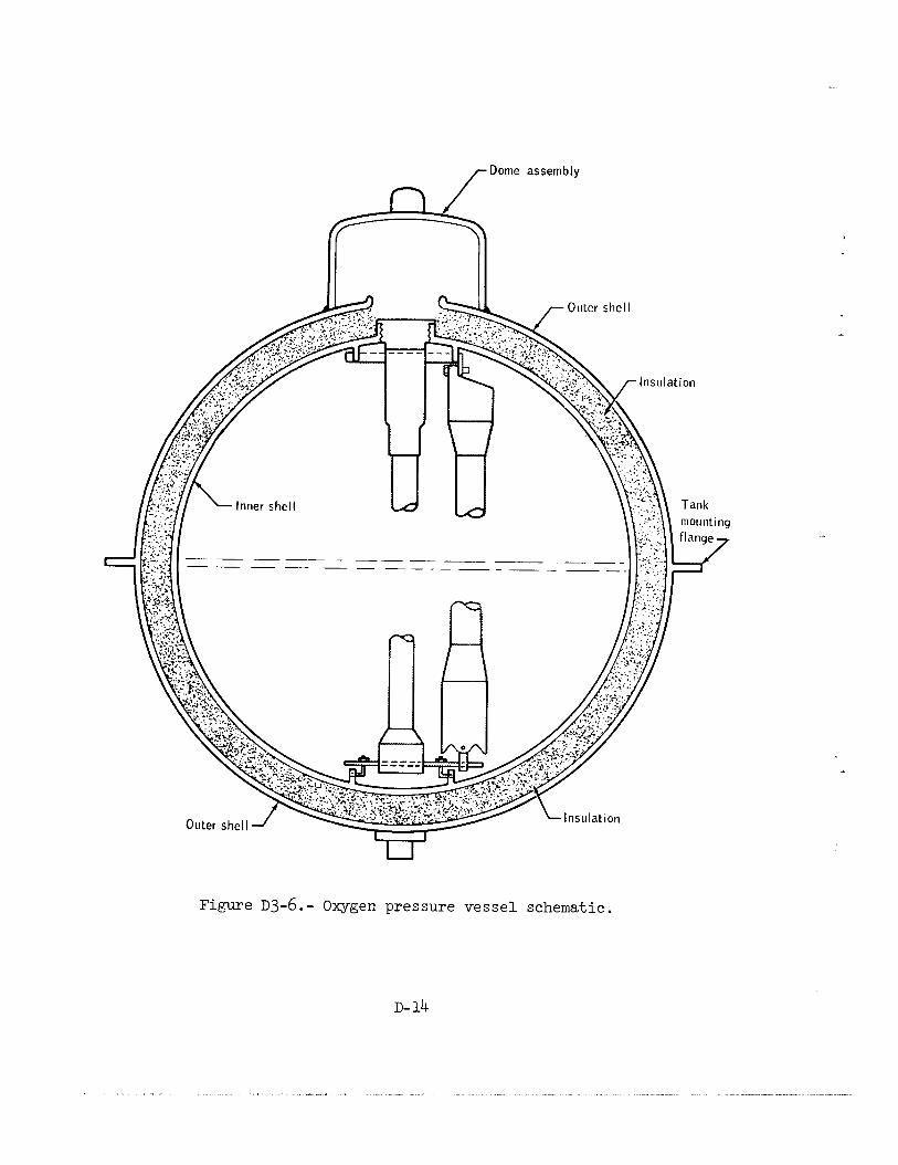
The oxygen tank consists of two concentric shells, an inner shell (the pressure vessel) and an outer shell (fig. ~3-6). The space between the two shells is evacuated during normal operation and contains the thermal insulation system, fluid lines, and the conduit which houses all of the electrical wires entering the pressure vessel.
.
The oxygen tank is discussed from the standpoint of materials, pro- cessing, welding, qualification program, stress levels, fracture analysis, and environmental testing.
Materials, Processing, and Welding
Inner shell.- The pressure vessel is made from Inconel 718, a pre- cipitation hardenable nickel base alloy having good strength, ductility, and corrosion resistance over the range of temperatures from -300" F to above 1400" F. The nominal composition of Inconel 718 is 19 percent chromium, 17 percent iron, 0.8 percent titanium, 5 percent columbium, 0.6 percent aluminum, and the remainder nickel. The heat treatment specified for Inconel 718 for this application was the following:
Hold at 1800~ F t 25" F for 1 hour
Air cool to 1325 ? 25" F and hold for 8 hours
Furnace cool to 1150" F and hold for 8 hours
Air cool
This treatment should produce typical ultimate tensile strength of 198,000 psi and yield strength of 170,000 psi at 70" F. Ultimate and
D- 13
/-Dome assembly
--~ - ---- ~ - -- --------
Figure ~3-6.- Oxygen pressure vessel schematic.
D- 14
yield-strength values increase with decreasing temperature and reach 228,000 psi and 189,000 psi, respectively, at -190" F. These values ex- ceed those assumed in the design of the vessel, which were 180,000 psi ultimate tensile strength and 150,000 psi yield strength at room tempera- ture (ref. 2). After burst tests, tensile specimens were cut from test vessels PV-1 and PV-4, and strength measurements were made at room tem- perature. Each specimen exceeded minimum requirements.
Inconel 718 is considered to be an excellent selection for use at the temperatures required by this design and when properly cleaned is compatible with liquid oxygen.
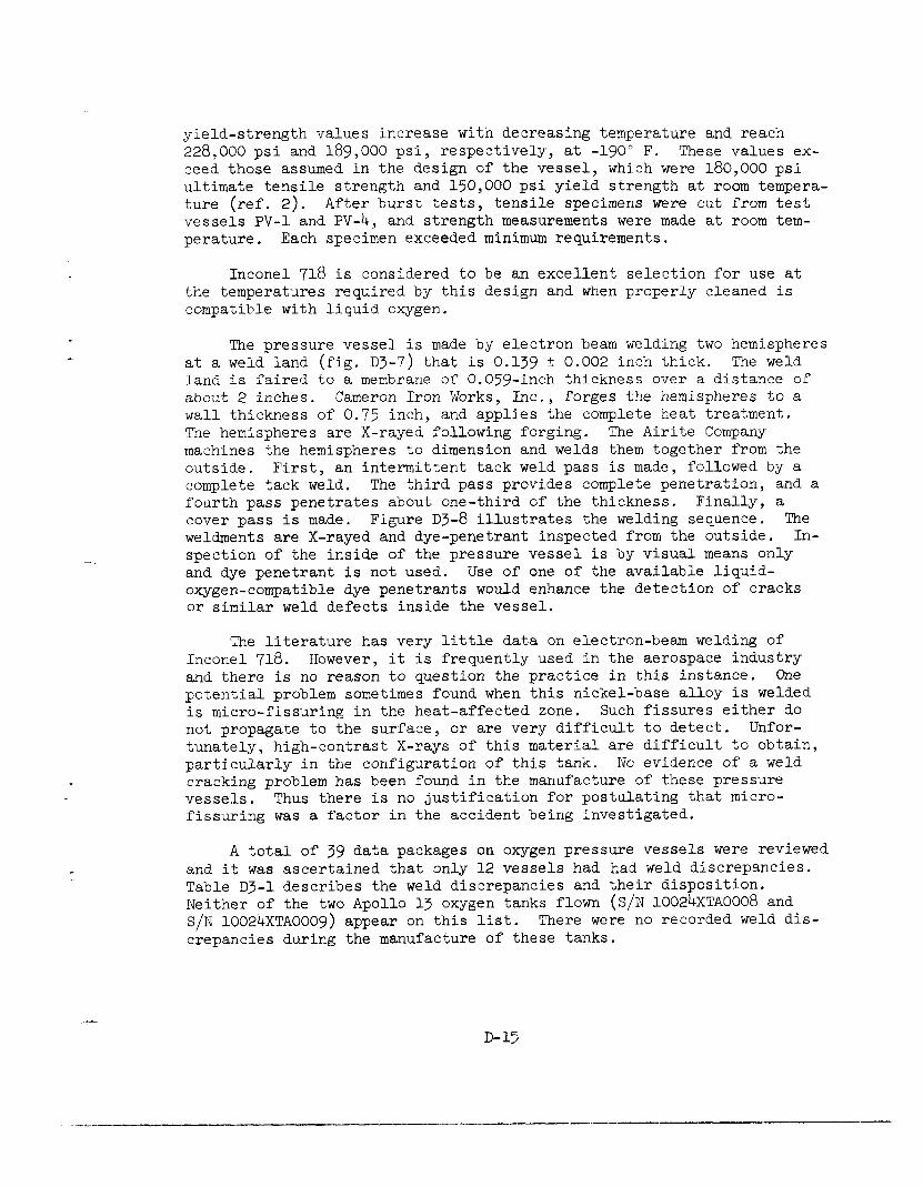
The pressure vessel is made by electron beam welding two hemispheres at a weld land (fig. D3-7) that is 0.139 2 0.002 inch thick. The weld land is faired to a membrane of 0.059-inch thickness over a distance of about 2 inches. Cameron Iron Works, Inc., forges the hemispheres to a wall thickness of 0.75 inch, and applies the complete heat treatment. The hemispheres are X-rayed following forging. The Airite Company machines the hemispheres to dimension and welds them together from the outside. First, an intermittent tack weld pass is made, followed by a complete tack weld. The third pass provides complete penetration, and a fourth pass penetrates about one-third of the thickness. Finally, a cover pass is made. Figure ~3-8 illustrates the welding sequence. The weldments are X-rayed and dye-penetrant inspected from the outside. In- spection of the inside of the pressure vessel is by visual means only and dye penetrant is not used. Use of one of the available liquid- oxygen-compatible dye penetrants would enhance the detection of cracks or similar weld defects inside the vessel.
The literature has very little data on electron-beam welding of Inconel 718. However, it is frequently used in the aerospace industry and there is no reason to question the practice in this instance. One potential problem sometimes found when this nickel-base alloy is welded is micro-fissuring in the heat-affected zone. Such fissures either do not propagate to the surface, or are very difficult to detect. Unfor- tunately, high-contrast X-rays of this material are difficult to obtain, particularly in the configuration of this tank. No evidence of a weld cracking problem has been found in the manufacture of these pressure vessels. Thus there is no justification for postulating that micro- fissuring was a factor in the accident being investigated.
A total of 39 data packages on oxygen pressure vessels were reviewed and it was ascertained that only 12 vessels had had weld discrepancies. Table D3-1 describes the weld discrepancies and their disposition. Neither of the two Apollo 13 oxygen tanks flown (S/N 10024XTAOOO8 and S/N 10024XTAOOOg) appear on this list. There were no recorded weld dis- crepancies during the manufacture of these tanks.
D- 15

Joint configuration -0.D. surface
e--_,
T .lll’.““’
El rnh,*
1
rer’ A ! 1.
I
I .130 r I tYPJ I I
‘1 ‘L-.o1o;g!f; z - I.D. surface
t 0.111+
test coupons
l Weld reinforcement
P/M thickness L T
1.000 .084 f.002
2.000 .067 f.002
3.000 + 004
.059, of-)(-J
Tank radius Dimensions
O.D. I.D.
14.808 12.528 +005
refarc -0 Sph rad
14.808 +005
refarc 12.528 m. Sph rad
+005 12.587 refarc 12.528 -0 Sph rad
Weld schedule (Electron beam weld)
Pass sequence Parameter l-tack 2-seal 3-pene. 1 4-pene.2 5-cover
Voltage - Kv 80 80 115 95 85 Amperes - MA 1.5 1.5 6.0 4.0 3.0 Beam deflection - in. 0.012 0.012 .024/ .036 .040/.080 0.110 Travel - in./min 18 - -
Vacuum - mm hg 2x10⁻⁴ - = c __c
Notes: (1) 0.002” gap, 0.003” offset (max typ) (2) No weld repairs allowed (3) Typical weld sequence shown on attached sketch
Figure D3-7.- Girth weld joint configuration and schedule.
D-16
-002
c -......-” . _- .--..--- ---_ - -” . . . . . . ..- -._---.._._. ._. l.-.~--l-~l”_ _,_- *-_-- .-....._- “.l-_--_---llll~~-~.

t
.112 ref weld reinf
+
0. D. surface Pass 1 and 2 (tack and seal)
I <’
I.D. surface
Fusion zone 7
Pass 3 (penetration 1)
r Pass 4 (penetration) Pass 4 (penetration)
r Pass 5 (cover)
!2 (Completed weld)
Figure D3-8.- Weld sequence.
D-17
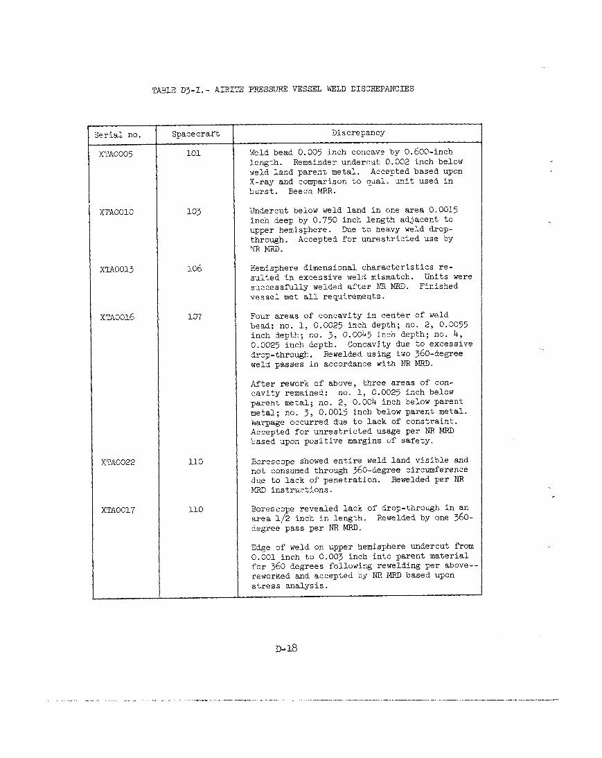
TABLE Dj-I.- AIRITE PRESSURE VESSEL WELD DISCREPANCIES
Serial no. Spacecraft Discrepancy
XTAOO05 101 Weld bead 0.005 inch concave by 0.600-inch length. Remainder undercut 0.002 inch below weld land parent metal. Accepted based upon X-ray and comparison to qual. unit used in burst. Beech MRR.
XTAOOlO 103 Undercut below weld land in one area 0.0015 inch deep by 0,750 inch length adjacent to upper hemisphere. Due to heavy weld drop- through. Accepted for unrestricted use by NRmD.
XTAOOl3 106 Hemisphere dimensional characteristics re- sulted in excessive weld mismatch. Units were successfully welded after NR MRD. Finished vessel met all requirements.
~~~0016 107 Four areas of concavity in center of weld bead; no. 1, 0.0025 inch depth; no. 2, 0.0055 inch depth; no. 3, 0.0045 inch depth; no. 4, 0.0025 inch depth. Concavity due to excessive drop-through. Rewelded using two 360-degree weld passes in accordance with NR MRD.
After rework of above, three areas of con- cavity remained: no. 1, 0.0025 inch below parent metal; no. 2, 0.004 inch below parent metal; no. 3, 0.0015 inch below parent metal. Warpage occurred due to lack of constraint. Accepted for unrestricted usage per NR MRD based upon positive margins of safety.
XTAO022 110 Borescope showed entire weld land visible and not consumed through 360-degree circumference due to lack of penetration. Rewelded per RR MRD instructions.
XTAO017 110 Borescope revealed lack of drop-through in an area l/2 inch in length. Rewelded by one 360- degree pass per RR MRD.
Edge of weld on upper hemisphere undercut from 0,001 inch to 0.003 inch into parent material for 360 degrees following rewelding per above-- reworked and accepted by NR MRD based upon stress analysis.
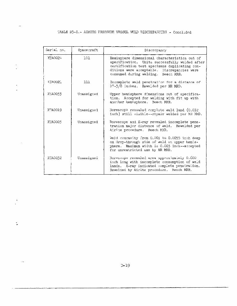
TABLE D3-I.- AIRITE PRESSURE VESSEL WELD DISCREPANCIES - Concluded
-.
c
Serial no. Spacecraft
XTAOO24 111
XTAO021 111
xTAoo33 Unassigned
XTAOOl9 Unassigned
XTAOO03 Unassigned
Discrepancy
Hemisphere dimensional characteristics out of specification. Units successfully welded after certification test specimens duplicating con- ditions were acceptable. Discrepancies were consumed during welding. Beech MRR.
Incomplete weld penetration for a distance of 17-3/8 inches. Rewelded per NR MRD.
Upper hemisphere dimensions out of specifica- tion. Accepted for welding with fit up with another hemisphere. Beech MRR.
Borescope revealed complete weld land (0.012 inch) still visible --repair welded per NR MRD.
Borescope and X-ray revealed incomplete pene- tration major distance of weld. Rewelded per Airite procedure. Beech MRR.
Weld concavity from 0.001 to 0.0055 inch deep on drop-through side of weld on upper hemis- phere. Maximum width is 0.003 inch--accepted for unrestricted use by NR KRD.
XTAO032 Unassigned Borescope revealed area approximately 0.600 inch long with incomplete consumption of weld lands. X-ray indicated complete penetration. Rewelded by Airite procedure. Beech MRR.
D-19
Outer shell.- The outer shell is made of Inconel 750, also a nickel base alloy having the following nominal composition: 15 percent chromium, 7 percent iron, 2.5 percent titanium, 1 percent columbium, 0.7 percent aluminum, and the remainder nickel. According to references 3 and 4, the outer shell can be annealed. Typical strength values for the annealed alloy are 130,000 psi ultimate strength and 60,000 psi yield strength. This is more than adequate for this application. The wall thickness of the outer shell is 0.020 + 0.002 inch. When the space between the two shells is evacuated, the outer shell preloads the insulation between the two shells. The dome of the outer shell contains a burst disc designed to vent the space between the shells to ambient pressure at a pressure differential of 75 * 7.5 psi.
Cryogenic tank tubing.- Three fluid lines (fill line, vent line, and feed line), and an electrical conduit are fusion welded to the close-out cap (tube adapter) that is screwed into the top of the pressure vessel. The cap is secured to the pressure vessel by a circumferential seal weld. The four lines are made of Inconel 750, annealed Aerospace Materials Specification (AMS) 5582. The tubes traverse the space between the two shells and exit the outer shell at the side of the tank coil cover. The nominal strength of the annealed tubing is 140,000 psi ultimate, and 80,000 psi yields, which is more than adequate for the application, as the stress level in the tubing is only about 17,000 psi.
After the tubes are welded to the cap, a visual inspection, helium leak test (3 psi), and proof-pressure tests are used to assess the quality of these welds (ref. 5). This is reasonable because of the low stress levels involved. Liquid-oxygen-compatible dye penetrant inspec- tion and subsequent cleaning would enhance the possibility of finding surface cracks. X-rays of these welds would be difficult to obtain and should be of dubious value.
The four lines extend only a few inches from the tank dome. When the tank is assembled on the oxygen subsystem shelf, the fluid tubes are joined by brazing to the 304L annealed corrosion resistant steel tubes of the spacecraft systems. Although joining Inconel 750 and 304L steel constitutes a bimetallic couple, it is satisfactory in this application because of the dry environment that is maintained.
Qualification Program
The pressure vessel qualification program was conducted by Beech Aircraft Corporation. Four pressure vessels were subjected to burst tests as described in references 6 through 12.
Prior to each burst test, the vessel was subjected to an acceptance pressure test at 1357 psig and checks were made for leaks. No leaks were
D-20
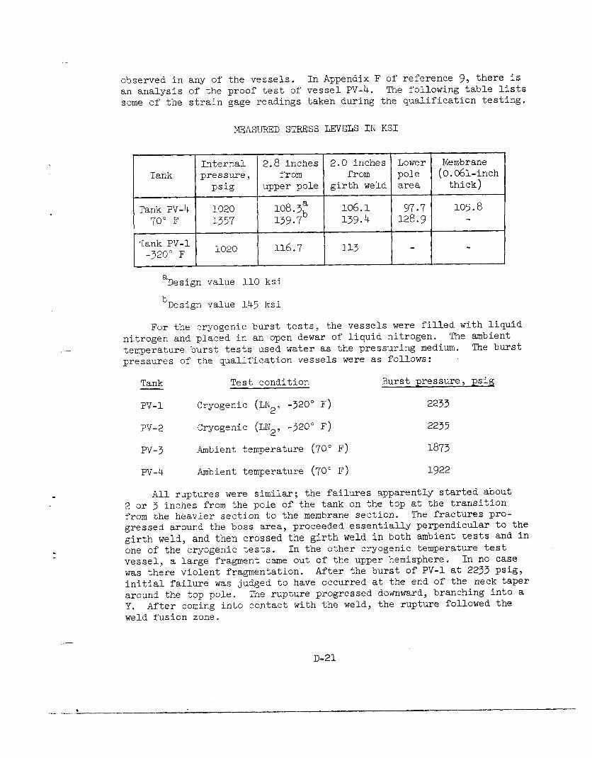
observed in any of the vessels. In Appendix F of reference 9, there is an analysis of the proof test of vessel PV-4. The following table lists some of the strain gage readings taken during the qualification testing.
MEASURED STRESS LEVELS IN KS1
Internal 2.8 inches 2.0 inches Lower Membrane Tank pressure, from from pole (0.061-inch
psig upper pole girth weld area thick)
Tank PV-4 1020 108.3" 106.1 97.7 105.8 70" F 1357 139.7b 139.4 128.9 -
Tank PV-1 -320" F 1020 116.7 113
"Design value 110 ksi
b Design value 145 ksi
For the cryogenic burst tests, the vessels were filled with liquid nitrogen and placed in an open dewar of liquid nitrogen. The ambient temperature burst tests used water as the pressuring medium. The burst pressures of the qualification vessels were as follows:
Tank Test condition Burst pressure, psig
PV-1 Cryogenic (LN2, -320" F) 2233
PV-2 Cryogenic (LN2, -320" F) 2235
PV-3 Ambient temperature (70" F) 1873
PV-4 Ambient temperature (70" F) 1922
All ruptures were similar; the failures apparently started about 2 or 3 inches from the pole of the tank on the top at the transition from the heavier section to the membrane section. The fractures pro- gressed around the boss area, p roceeded essentially perpendicular to the girth weld, and then crossed the girth weld in both ambient tests and in one of the cryogenic tests. In the other cryogenic temperature test vessel, a large fragment came out of the upper hemisphere. In no case was there violent fragmentation. After the burst of PV-1 at 2233 psig, initial failure was judged to have occurred at the end of the neck taper around the top pole. The rupture progressed downward, branching into a Y. After coming into contact with the weld, the rupture followed the weld fusion zone.
D-21
The following is a quotation from reference 9:
"2.3.7 Conclusions - Based on the above analysis and evaluation, the following conclusions are made:
(1) Burst failure initiated at the end of the boss taper in the upper hemisphere and resulted from plastic deformation beyond the tensile strength of the base material at ambient tem- perature.
(2) Rupture was of a hydrostatic type.
(3) The appearance of all failed areas was judged to indicate good ductility of the base metal and weldments.
(4) No significant mismatch was observed on the specimens investigated.
(5) All fractures across the weld were shear fractures and of a secondary nature.
(6) The grain size throughout the vessel was fine (ASTM-5 to 8) and relatively equiaxed.
(7) The ambient burst test was judged to be completely successful by Beech Aircraft Cor- poration Engineering, and the results of the test indicate approximately 100 percent ef- ficiency for the material at the test tem- perature."
The data from these pressure vessel tests satisfy the qualification requirement for an ultimate factor of safety of 1.5 at ambient tempera- ture with adequate margins.
In 1967 North American Rockwell verified analytically the structural integrity of the oxygen tank (ref. 13). An MSC structural analysis re- port (ref. 14), also issued in 1967, confirmed the structural integrity of these tanks and compared the analysis with the results of the burst tests. This comparison showed good correlation between analytical and test results. The MSC calculations were based on minimum guaranteed sheet thicknesses and minimum material properties. Even better correla- tion is obtained by using the actual thicknesses and material properties of the test items.
D-22
“-. .._.,_._ ^” .l.--_._--^. _---- __..,_ -_ . . . ..e_.._-“.-- -.-.--.
,,-- _,__ .__- “.- ____.
_ . I , . . ._ . * _.___. .-__..., ^..“.-.“. .- --.. .

These analyses show the maximum stresses in the tank during pressur- ization to be in the upper spherical shell at the transition from the constant thickness shell to the thickened area adjacent to the penetra- tion port. Actual stresses determined from strain gage readings during burst tests are consistent with the analyses.
FRACTURE MECHANICS
The design of the supercritical oxygen tank was based on conven- tional elastic stress analysis which assumes a homogenous material and uses the conventional tensile properties for the calculation of safety factors. In reality, all fabricated materials contain crack-like flaws which may be associated with weld defects or with metallurgical segrega- tions which can transmit only negligible loads across their boundaries. The load-carrying capacity of high-strength materials, particularly in thick sections, may be severely reduced by the presence of even small flaws which can trigger a brittle catastrophic failure at loads well below those considered safe by conventional design procedures. Further- more, in many cases the type of flaw present cannot be found by non- destructive inspection techniques and, for this reason, a proof test must be depended upon to identify those structures which might fail in service.
At the outset it should be appreciated that linear elastic fracture mechanics and the associated American Society of Testing Materials (ASTM) Standard Method of Test for Plane Strain Fracture Toughness, KIc, are not
directly applicable to an analysis of the fracture of the oxygen pressure vessel material in the thicknesses employed, or for that matter in very much larger thicknesses. The evidence for this lies in early results from a fracture test program now underway at Boeing. These results in- dicate that specimens containing deep cracks in parent metal, or in electron beam weld metal representative of the oxygen pressure vessel, fail at net stresses very close to or slightly above the corresponding yield strength whether they are tested at 70" F or -190" F. While the plane strain fracture toughness, KIc, cannot be determined from the data
available, a lower bound estimate may be made from test results reported on 2-3/4 inch diameter notched round bar specimens (ref. 15). These large specimens were cut from forgings of Inconel 718 and tested at -110" F. The corresponding yield strength was about 172 ksi and the notch strength was 40 percent above the yield stren th.
de Formal calcula-
tions give an "apparent KIcIt value of 190 ksi - which may be taken
as a lower bound for a yield strength of 172 ksi. This is approximately equal to the 70" F parent metal yield strength of the oxygen pressure vessel. Properly made electron beam weldments should have at least this
~-23
high a KIc value since they are not heat treated after welding and there-
fore have a lower yield strength than the parent metal. At -190" F the yield strength of the parent and weld metal will increase about 10 per- cent; however, for this austenitic alloy the corresponding change in toughness would be expected to be negligible.
Failure Modes
While "apparent KIc' values should not be used to develop relations
between tank wall stress and critical flaw size, the lower bound value
Of KIc can be used to show that the pressure vessel would not fail in
a brittle manner. When the parameter PI,, the ratio of crack tip
plastic zone size factor to specimen thickness, is greater than l-1/2, brittle fracture is very unlikely. This parameter is given by
P 1 KZIc =--
Ic B, 2
For the olrygen is 0.111 inch;
(table D3-II),
tank B the effective weld land thickness after welding the yield strength of the weld F,-- is 110 ksi at -190' F
and the lower bound of KIc is 190 ksi - q. .
TABLE ~3-11. - TYPICAL PARENT METAL AND WELD TENSILE PROPERTIES"
Parent metal Weld metal Temperature, a F F - ksi - ksi
tu -ksi F
tY - ksi
Ftu FtY
-190 228 189 187 b
110
70 198 170 158 iO0
"Determined by Boeing on Inconel 718 forgings using same heat treatment given the oxygen pressure vessel and on electron beam weld- ments given no heat treatment.
b Gage length equal to weld width.

Using these values, @I, = 27. A similar calculation for the parent metal
in the membrane yields % = 16. On this basis, the mode of failure
of the pressure vessel would be expected to be ductile tearing rather than shattering. However, it is not known whether this mode would lead to a stable through-thickness crack, and a consequent slow leak into the space between the pressure vessel and the outer shell, or to a rapid tearing fracture with consequent destruction of the outer shell and the quick release of a large volume of oxygen. Which of these two possibilities is most likely depends in part on the flaw size giving rise to the final fracture and on the rate of depressurization as compared with the rate of crack propagation. To settle this matter would require burst tests on intentionally flawed tanks.
If a local area of the pressure vessel wall or the tube adapter were heated to a sufficiently high temperature by some internal or external source, the tank would blow out at this local area. According to data furnished by Boeing under contract to NASA, the strength of Inconel 718 would degrade rapidly if the metal temperature exceeded about 1200' F. At 1400' F the tensile strength would be about 50 percent of the room temperature value, and at 1600' F would be less than 30 percent of this value. At a tank pressure of 1008 psi, the parent metal wall stress based on membrane theory is about 108 ksi. A ductile rupture at this stress would likely occur if the tank were at a uniform temperature of 1400° F. The restraining effect of the cool surrounding metal would raise the temperature required for a local blowout snd this situation is best evaluated by suitable experiments.
Effectiveness of the Proof Test
The proof test is the last, and should be the best, flaw detection procedure applied to a pressure vessel. Ideally, the proof test should cause failure if there are any flaws present that could grow to a critical size during subsequent pressurization. For the oxygen tanks in question, a fracture mechanics analysis cannot be made to assess the adequacy of the proof test because of the high toughness of the material and the thin sections used. These factors in themselves, of course, contribute to the confidence that can be placed in the integrity of the pressure vessel and, as discussed in the previous section, essentially rule out the possibility of brittle failure. However, it is worthwhile to estimate the effectiveness of the proof test in identifying those pressure vessels which might develop leaks during pressure cycles subsequent to proof. The failure model proposed considers the plastic instability fracture of a ligament of material produced by incomplete fusion during electron beam welding. The main features of this model are illustrated in fig- ure D3-9. It essentially represents a long flaw in the tank wall at the
D-25

Area of lack of fusion produces an effective crack of depth A & length 2C in tank wall of thickness B. 2C -A
Figure D3-9.- Ligament model for ductile fracture of pressure vessel.
~-26
..-e... ._ ,_ 1 _..., .
equatorial weld. It is postulated that the ligament will fail when its stress reaches the tensile strength of the material. Calculations show that the ligament stress aR is related to the average wall stress
73 as follows:
B "a = ",B-A
where the dimensions are defined in figure D3-9. The maximum relative flaw depth that can be sustained without failure is then
A -=l- %L B
Ftu 0)
where F tu is the ultimate tensile strength. Failure will occur by
tearing of the ligament accompanied by rapid decompression of the tank. It should be appreciated that this is a rather crude model of ductile fracture, and will probably overestimate the failure stresses in a spherical vessel. However, it should be useful in assessing the effec- tiveness of the proof tests in light of subsequent service, because of the very large margins between proof and operating pressures.
The pressure cycles applied to the Apollo 13 oxygen tank no. 2 are shown in table D3-III. It should be noted that the oxygen tank no. 2 had several extra pressure cycles in addition to those normally applied. These were associated with rechecks for heat leaks and with the "shelf drop" incident. The additional cycles do not affect this analysis nor should they have reduced the integrity of the tank during mission service.
The ratio of tank pressures necessary to cause ligament failure for a given relative flaw size A/B at two temperatures- will be equal to the ratio of the tensile strength of the material at these temperatures. On this basis, the.maximum flaw size that could exist before CDDT is estab-
lished by the last high pressure helium proof specified as 1260 T'g psi
at ambient temperature (1276 psi for oxygen tank no. 2). From equation (l), the corresponding value of A/B for the weld metal is 0.55, based on a weld tensile strength of 158 ksi at room temperature, a weld land thickness of about 0.111 inch, and a nominal weld land stress of 71 ksi.
The question now arises as to whether a flaw of this size could propogate through the wall during subsequent pressurization and produce a leak. Flaw growth could occur by sustained loads or cyclic loads. In the absence of an aggressive environment, it is generally recognized that sustained load flaw growth will not occur at loads less than 90 percent of that necessary to produce failure in a continuously rising
D-27

TABLE DJ-III.- HISTORY OF P~SSJRE CYCLES APPLIED TO APOLLO 13 SUPERCRITICAL OXYGEN TANK NO. 2
[Record from North American Rockwell Space Division]
Crganization
Beech
Beech
Beech
Beech
Beech
Beech
Beech
Beech
Beech
Beech
Test media Date
H20 + He 6-20-66
GN2 7-15-66
LN2 7-15-66
GN* g-15-66
LN2 9-15-66
Helium lo-19-66
Helium 10-19-66
LOX 12-20-66
LOX 10-24-66
Helium 1-31-67
LOX 2- 2-67
LOX 2- 3-67
Helium 4-29-68
Helium 5- 1-68
Helium 5- l-68
Helium 5- 2-68
Helium 5-27-68
Helium 5-28-68
Helium U-18-68
Helium 11-18-68
Helium 7-17-69
LOX 4- g-70
EPressure cycles below 400 psi not recorded
Beech
Beech
NAR-SD
NAR-SD
NAR-SD
NAR-SD
NAR-SD
NAR-SD
IXAR-SD
NAR-SD
NAR-SD
NAR-SD
Peak pressure, psi
(a), b)
1336
Time, hr:min
00:24
1340 00:56
920 00:51
c1333 00:54
'918 00:51
1303 09:49
888 01:oo
1333 40:05
922 25:04
c13o5 og:o7
'1321 28:39
cg20 22:16
1262 06:45
1002 01:oo
968 13:13
1104 08~02
'jd1262 02:54
Y102 01:07
d1276 02:24
1002 01:40
1025 01:3g
925 43:53
Test name
Pressure vessel, acceptance
Internal leak check on complete assembly
Cold shock
Internal leak check
Cold shock
Proof and leak
Proof and leak
dddm
Q/h
Proof and leak
Q/b
dq/h
Leak
Leak
Leak
Leak
Leak
Leak
Leak
Leak
Leak
Launch loading
:It could not be determined whether pressure measurements represented psia or psig Pressure cycles not normally applied
d1260 r'z psi specification
~-28
.._,_~ _ __ _ --,_ ..-._._ ._ . ...” _---.- ..~~“‘.--.~“..“.l”“...l- . ..- ----.-----..-...--i __* .._l.“.._. _ .._--”

load test. Following the 1276 psi helium proof test, no subsequent pressurization exceeds 85 percent of this pressure, and consequently sustained load flaw growth is extremely unlikely. Confidence in this conclusion can be obtained from the test results of a Boeing program now underway. These results apply to specimens containing small but deep cracks in both parent metal and electron beam weld metal of Inconel 718 forgings heat treated in the same way as the oxygen tank material. The early data show no crack growth in 20 hours at -190' F for specimens subjected to 160 percent of the nominal operating stress.
Cyclic loads during the flight operation would be caused by cyclic operation of the heaters (about once per one-half hour). The associated pressure cycles are very small with a minimum-to-maximum stress ratio of about 0.93. Flaw growth due to these small cyclic loads is con- sidered extremely unlikely during the mission for the following reason: maximum nominal operating stress in the weld land (at 935 psi) is about 28 percent of the weld tensile strength at -190" F. Therefore, with a flaw size of A/B = 0.55, the ligament stress would be only about 63 per- cent of the weld tensile strength. On the basis of the known fatigue behavior of Inconel 718 welds (ref. 16), it would be expected that ligament failure due to cyclic loads induced by heater operation would not be a consideration until hundreds of cycles had been accumulated. Confidence in this conclusion can be obtained from the early results of the previously mentioned on-going Boeing program. These results in- dicate that parent and electron beam weld metal specimens of Inconel 718 containing small but deep cracks do not show crack growth at -190" F after 15,000 cycles at minimum-to-maximum stress ratio of 0.95 and a mean stress of about 170 percent of the nominal operating value.
While the conclusions based on the ligament model are consistent with the Boeing data obtained from specimens with small flaws, these test results cannot be used to prove the validity of the model because it applies to large flaws. Therefore, it is planned to check the con- clusions reached on the basis of this model by testing specimens at MSC which will contain large, deep cracks. Specimens of both electron beam welds and parent metal will be subjected at -190" F to the mean and cyclic stresses encountered in flight operation of the oxygen tank.
In assessing the effectiveness of the proof test, no consideration was given to the possibility of failure in regions remote from the welds (e.g., the main membrane or neck of the vessel). Conventional stress analysis (ref. 14) shows that the highest stresses occur in the transition region between the weld lands and the uniform thickness membrane. Stresses in the neck region are very low and comparable to those in the weld land. The ligament model is not applicable to these regions of the vessel remote from the weld since there is no clear mechanism by which a large flaw could be introduced into the parent metal. Experience shows that
D-29
_---.“..- “- ...-- _

crack-like imperfections are sometimes introduced by the forging process, but these are relatively small and confined to the surface layers of the forging. Such defects are easy to detect and are usually removed by the machining process. It is the standard practice of the aerospace industry to reject forgings that have cracks that cannot be removed by machining. With this in mind, there is no reason to doubt the effective- ness of the final high-pressure helium proof test insofar as the pressure vessel main membrane area is concerned.
Possibility of Tank Failure During Apollo 13 Mission
On the basis of the foregoing information, it is extremely unlikely that the oxygen tank no. 2 pressure vessel ruptured at the maximum record- ed flight pressure of 1008 psi and temperature of -160" F because of crack propagation. Based on the previously described ligament model, a pressure vessel passing the last high-pressure helium proof test should withstand a, pressure load nearly twice that of the maximum flight pressure at -160' F. As described previously, a high-temperature blowout of the pressure vessel is entirely possible, and if this occurred the fluid released could have caused rurU n+ure of the dome or of the outer shell.
DYNAMIC TESTING
During the development and qualification of the command and service modules (CSM), a series of dynamic tests was conducted on major vehicle elements as well as subassemblies. The following sections describe those tests applicable to the cryogenic oxygen tank.
Oxygen Tank Assembly Dynamic Testing
Dynamic testing was accomplished during September 1966. Flight-type oxygen tank assembly hardware, selected as a test specimen, successfully completed this testing as documented in reference 17.
Vibration testing.- The test specimen was subjected to vibration in each of three axes, and the vibration level was maintained for 15 minutes in each axis. The specified test levels, representing the combined envelope of the atmospheric and space flight conditions, were as follows:

Frequency, Hz g2/Hz
.
10 0.003
10-90 0.003 to 0.025 at 3 dB/octave
90-250 0.025
250-400 0.025 to 0.015 at 3 dB/octave
400-2000 0.015
The test spectrum is shown as the solid line in figure D3-10. No signifi- cant anomalies were recorded during these tests. These tests qualified the oxygen tank assembly for the launch and space flight conditions.
Acceleration testing.- The oxygen tank assembly used in the vibra- tion testing mentioned in the preceding paragraph was also tested for acceleration in each of three axes for at least 5 minutes in each di- rection. The acceleration was 7g in the launch axis direction and 3g in the other two orthogonal axes. These accelerations are greater than those expected during normal ground handling or during flight. No anomalies were recorded during these tests.
Apollo CSM Acoustic and Vibration Test Program
In addition to the dynamic testing previously described, the oxygen tank and shelf assemblies plus other CSM subsystems were tested as part of the Block II, Spacecraft 105/AV Certification Test Program conducted during February and March 1968 (ref. 18). These tests qualified the Block II CSM hardware against the acoustic and vibration criteria, and confirmed the structural integrity of the CSM for vibration inputs which enveloped the complete ground and flight environmental requirements as specified in reference 19.
Figure D3-11 shows the transducer locations used for both the acous- tic and vibration testing. Test instrumentation in the area of the oxygen tank was as follows:
SA 110 (+X) Oxygen shelf on bracket, 18 inches from beam 4
SA 111 (-R) Oxygen shelf on bracket, 18 inches from beam 4
SA 112 (-T) Oxygen shelf on bracket, 18 inches from beam 4
SA 113 (+X) Oxygen shelf on centerline
Note: R = radial, T = tangential
D-31

1 .O
-Mbasu~rer$e&s &id:-. I I
I, I SA107 SA108 SA109
Frequency, Hz (cps)
Figure D3-10 .- Service module data overlays and specified test spectrum.
D-32
- -.. _ ..___ I_. _ .L ___ ,...1..” --1- “-.-.lll_-~-“~“.,--~_--..X-.-- _..,_, _-.-- ._-.
-__- I __
SA168.---
SAM9 SAlrn
SAmA-
FWD BULKHEAD
/BEAM 4
) SA104 SAl05 SAl06
O2 LINE SLIPPORT BRACKET
-.SAllO
SAlll SA112
0 SA107 $A108 SA109
I42 LINE SUPPORT ~IRACKET
- -
A UNIAX ACCELEROMETER 0 TRIAX ACCELEROMETERS
Figure D3-ll.- Spacecraft 105/AV service module instrumentation, bay 4.
D-33
Vibration testing consisted of sinusoidal sweeps in the 4- to 30-Hz range, followed by sinusoidal dwells at the prominent resonance fre- quencies. CSM vibration response was controlled to 0.075-inch double amplitude for the 4- to &Hz frequency range and O.lg peek for the 7-
to 30-Hz frequency range.
Acoustic tests were performed to measure the vibratory response in the 20- to 2000-Hz frequency range. The acoustic spectrum of interest for the oxygen tank was adjusted to obtain a test spectrum as shown in figure D3-10.
The vibration and acoustic tests were completed without failures or any pertinent anomalies in the oxygen tank or tank shelf. The maximum observed accelerations during the tests are given in the - following table:
Inst. no.
SA 110
SA 111
SA 112
SA 113
Vibration
X-axis Z-axis 4- to 30-Hz sweep, 4- to 30-Hz sweep,
g (-1 g (=ns)
0.02 0.05
.5 95
.5 .6
.I5 .4
Acoustic
X-axis 4- to 30-Hz sweep,
g (-1
0.005
l 35
.6
.17
The responses of four transducers (SA 107 through SA 109 and SA 113) are shown in figure D3-10.
The tests confirmed the following:
1. Structural integrity of Block II CSM wiring, plumbing, bracketry, and installed subsystems when subjected to the dynamic loads resulting from spacecraft exposure to the aerodynamic noise environment expected during atmospheric flight.
2. Structural integrity of the Block II CSM when it is experiencing the low vibratory motions produced by atmospheric flight.
D-34
. ..* ‘. -. . ..-

Based upon the results, it is concluded that the tests were ade- quate to qualify the CSM for flight on the Saturn V. Of course, this qualification would not necessarily cover abnormal conditions such as mishandling.
SHOCK TESTING
Although NR specification (ref. 20) requires qualification testing of the oxygen tank assembly inside its shipping container for ground handling and transportation conditions, further investigation revealed that this requirement was deleted on January 8, 1965. This deletion is documented in paragraph 3.8.4.3 of reference 21, which states, "Revised Apollo Test Requirements, no testing of transportation and ground hand- ling environments (shall be required). Packaging is designed to pre- clude exposure of components to environments beyond transportation levels." The shipping container (ref. 22) was reportedly shock tested during the development program in 1964 and successfully sustained the test environment described in reference 23. From these tests it was concluded that the shock attenuation system in the shipping container was acceptable. There was no requirement for shock testing of the oxygen tank assembly outside its shipping container.
INTNRNAL COMPONENTS
There are a number of components internal to the oxygen tank. These are individually discussed in the following sections.
Quantity Gage
The quantity gage capacitor (fig. ~3-12) consists of two concentric aluminum tubes which are adequately mounted and supported. The inner tube of the capacitor constitutes the extension of the fill line. The outer tube is perforated to insure access of the oxygen to the space between the capacitor plates. The relative position of the two plates is maintained by insulating Teflon separators. Shorting of the capaci- tor at the plates within the tank requires bridging of the gap between the tubes by a conductive material. Shorting could also be induced by the contact of bare lead wires resulting from insulation damage. The power input to the quantity gage is regulated and limited by the high impedance source of the signal conditioner. The spark that could be
D-35

Vent line and electrical conduit also pass throuah this adaptpr -
Fill Feed I/-Adapter cap inconel
Temperature sensor-
and quantity probe
Teflon adapter - Tubular elements of capacitor (aluminum)
*224 dia holes, two .232 places for heater and motor wiring
Hole for temperature sensor wiring
Probe is manufactured by Simmonds Precision Dmrhrt~. Inc.
Glass-filled teflon insulator
Temperature sensor element is mounted on this insulator
Inner tank
Figure ~3-12 .- Quantity gage.
D-36
generated is at the 7- to lo-millijoule level. The evidence provided by the data can be construed to indicate that the effects of the probe failure during flight were limited to data loss.
Heaters
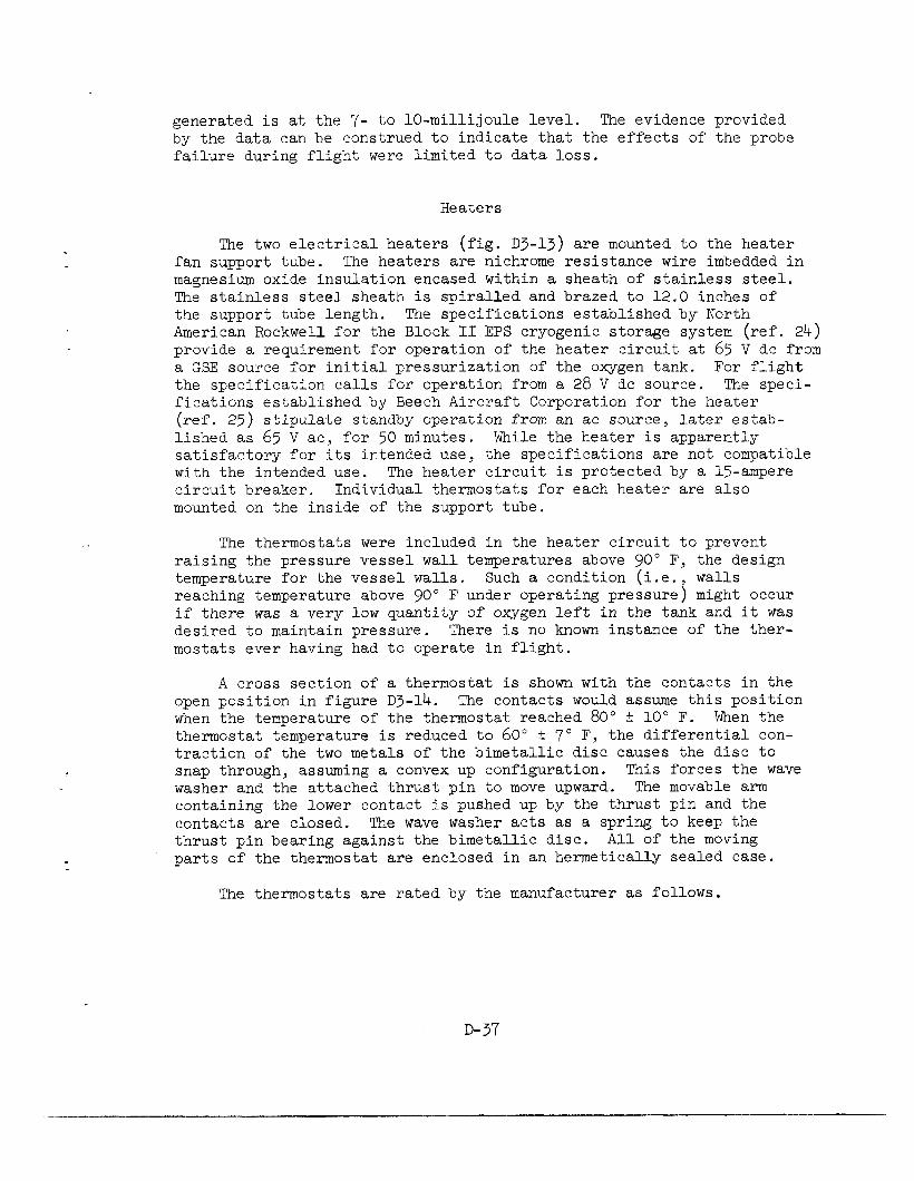
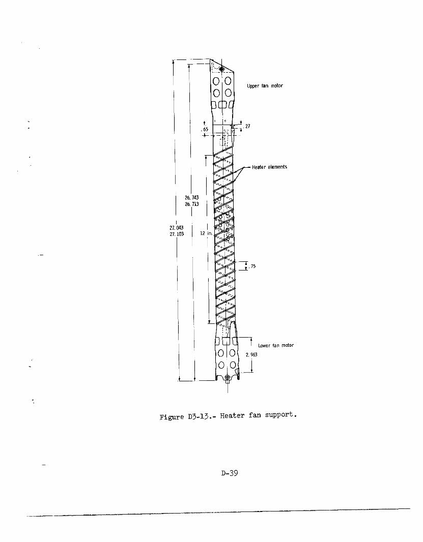
The two electrical heaters (fig. D3-13) are mounted to the heater fan support tube. The heaters are nichrome resistance wire imbedded in magnesium oxide insulation encased within a sheath of stainless steel. The stainless steel sheath is spiralled and brazed to 12.0 inches of the support tube length. The specifications established by North American Rockwell for the Block II EPS cryogenic storage system (ref. 24) provide a requirement for operation of the heater circuit at 65 V dc from a GSE source for initial pressurization of the oxygen tank. For flight the specification calls for operation from a 28 V dc source. The speci- fications established by Beech Aircraft Corporation for the heater (ref. 25) stipulate standby operation from an ac source, later estab- lished as 65 V ac, for 50 minutes. While the heater is apparently satisfactory for its intended use, the specifications are not compatible with the intended use. The heater circuit is protected by a Q-ampere circuit breaker. Individual thermostats for each heater are also mounted on the inside of the support tube.
The thermostats were included in the heater circuit to prevent raising the pressure vessel wall temperatures above 90" F, the design temperature for the vessel walls. Such a condition (i.e., walls reaching temperature above 90" F under operating pressure) might occur if there was a very low quantity of oxygen left in the tank and it was desired to maintain pressure. There is no known instance of the ther- mostats ever having had to operate in flight.
A cross section of a thermostat is shown with the contacts in the open position in figure D3-14. The contacts would assume this position when the temperature of the thermostat reached 80" f 10" F. When the thermostat temperature is reduced to 60" + 7" F, the differential con- traction of the two metals of the bimetallic disc causes the disc to snap through, assuming a convex up configuration. This forces the wave washer and the attached thrust pin to move upward. The movable arm containing the lower contact is pushed up by the thrust pin and the contacts are closed. The wave washer acts as a spring to keep the thrust pin bearing against the bimetallic disc. All of the moving parts of the thermostat are enclosed in an hermetically sealed case.
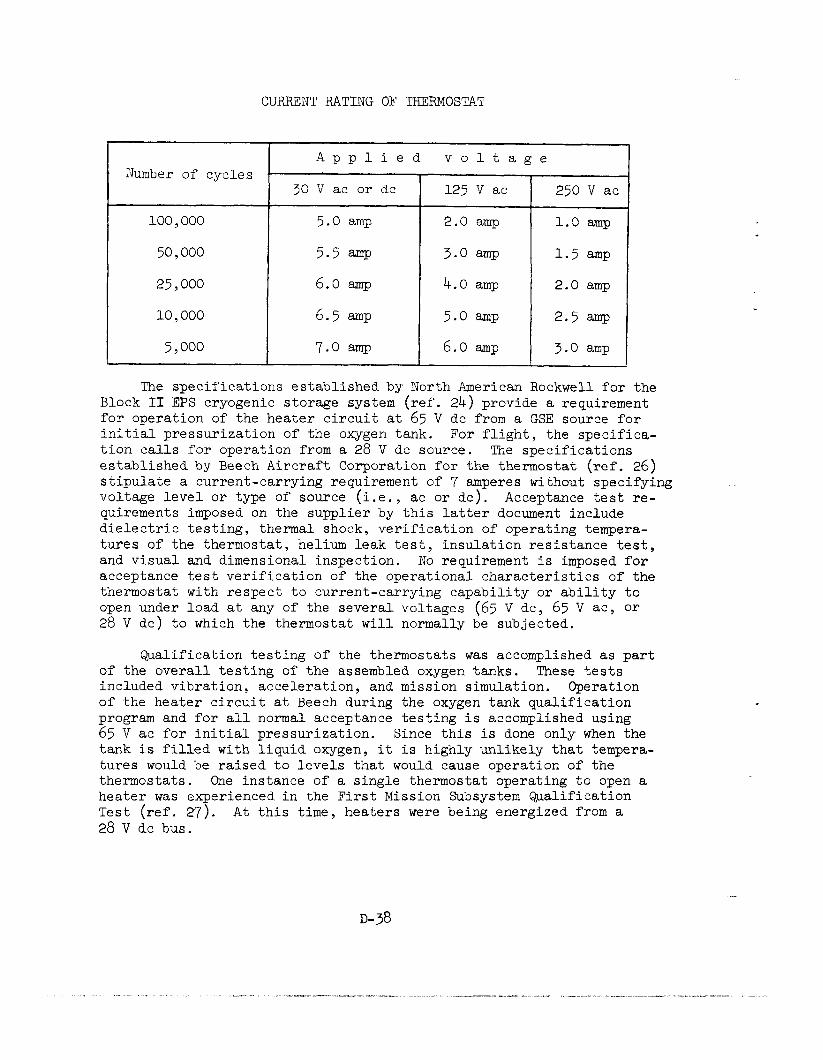
The thermostats are rated by the manufacturer as follows,
D-37
CURRENT RATING OF THERMOSTAT
I-
Number of cycles
100,000 5.0 amp 2.0 amp
50,000 5.5 amp 3.0 amp
25,000 6.0 amp 4.0 amp
10) 000 6.5 amp 5.0 amp
5,000 7.0 amp 6.0 amp
Applied voltage
30 V ac or dc I 125 v ac 2501
1.0 amp
1.5 amp
2.0 amp
2.5 amp
3.0 amp
The specifications established by North American Rockwell for the Block II EPS cryogenic storage system (ref. 24) provide a requirement for operation of the heater circuit at 65 V dc from a GSE source for initial pressurization of the oxygen tank. For flight, the specifica- tion calls for operation from a 28 V de source. The specifications established by Beech Aircraft Corporation for the thermostat (ref. 26) stipulate a current-carrying requirement of 7 amperes without specifying voltage level or type of source (i.e., ac or de). Acceptance test re- quirements imposed on the supplier by this latter document include dielectric testing, thermal shock, verification of operating tempera- tures of the thermostat, helium leak test, insulation resistance test, and visual and dimensional inspection. No requirement is imposed for acceptance test verification of the operational characteristics of the thermostat with respect to current-carrying capability or ability to open under load at any of the several voltages (65 V dc, 65 V ac, or 28 V de) to which the thermostat will normally be subjected.
Qualification testing of the thermostats was accomplished as part of the overall testing of the assembled oxygen tanks. These tests included vibration, acceleration, and mission simulation. Operation of the heater circuit at Beech during the oxygen tank qualification program and for all normal acceptance testing is accomplished using 65 V ac for initial pressurization. Since this is done only when the tank is filled with liquid oxygen, it is highly unlikely that tempera- tures would be raised to levels that would cause operation of the thermostats. One instance of a single thermostat operating to open a heater was experienced in the First Mission Subsystem Qualification Test (ref. 27). At this time, heaters were being energized from a 28 V de bus.
I”i”l Upper fan motor
26.143 26
27.043 2
.713
I
1.103
elements
Lower fan motor
.gure D3-13.- Heater fan support.
D-39

Moveable contact arm----\ r Glass seal
Thrust pi
L.015 in7 n9n :..
Wave washer Bi-metal disc
Figure D3-lb.- Cross section of thermostat.
D-40
_-
_._ l__.“-“_l_-~.-~.--------- x_I-__
,I --__-_ -- -_-.e----------- w-s-
-.__” .____ _---__L-. .-. -I- -.-.
__ __ - 1 --- .I-.

All qualification and acceptance tests identified were primarily concerned with the repeatability of the thermostat actuation at the specified temperatures. No qualification or acceptance tests have been identified which would verify the ability of the thermostats to open the heater circuit when energized at 65 V de.
The combination of incomplete, unclear, and therefore inadequate specifications of the thermostat with respect to voltage type and level and a test program that does not verify the ability of the switch to operate satisfactorily under service conditions constitutes a design deficiency. The fact that the ratings for the thermostat by the manu- facturer (preceding table) contains no entry for 65 V de indicates that service at this voltage was not intended.
At KSC, the heater circuits were intended to be operated at 65 V de only when the tanks were full of liquid oxygen. Under this condition, the thermostats would not be required to actuate. A discussion of the possible consequences of actuation of the thermostat under load at 65 V de is presented in a later section of this Appendix.
Fans
At the time the tanks were first designed, the knowledge of the behavior of fluids in zero-g was limited. It was believed that signi- ficant stratification of the fluid would occur during flight. Under these circumstances a number of difficulties could arise: a rapid pressure drop in the tank would be induced by the acceleration resulting from an SPS burn; the heaters might not be able to transfer heat uni- formly to the oxygen; and, finally, serious errors in quantity measure- ment could result. The occurrence of any of these conditions could jeopardize flight safety or mission success. For this reason, the tanks were provided with two motor-driven centrifugal fans to mix the fluid and insure its homogeneity.
The two oxygen fan motors (fig. D3-15) are three-phase, four-wire, 200/115-volt, 400-hertz, miniature, open induction motors, driving cen- trifugal flow impellers. The minimum speed of the motors is 1800 rev- olutions per minute at a torque output of 0.9 ounce-inches. The motors are mounted at each end of the motor-heater support tube by a canti- levered attachment joined to the motor back plate. The motor clearance within the support tube wall is a nominal 0.01 inch. The stator windings and bearings of the motors are exposed to oxygen.
The stator windings are fabricated with number 36 American Wire Gage (AWG) wire, using a Teflon-coated ceramic insulation. The ceramic insulation is brittle and subject to breakage if proper tension is not used in fabricating windings or if sharp bends are made at the winding

-
ti / in retainer
-
End of terminal
.
Figure D3-15.- Oxygen fan motor.
D-42
, ---- . ..-_ ,._
- I -----II-“----- .- -- ----.--.--- -...- _..,~ _,_-- “. “,__ --_-.. ._i .._.--__ -.I.I _-.. ^_
.---I I._ -_--___. .__-_

end turns. Acceptance testing of the wire is conducted on the first 100 feet of each reel. The wire is considered acceptable if no more than 10 breaks in insulation are exhibited in the sample when pulled through mercury at 25 feet per minute. The rejection rate for stator winding faults for motors processed early in the production run was substantial. Improved yield was achieved only by rigid adherence to the winding tension process control used in fabricating the windings, proper assembly techniques, and frequent in-process dielectric testing. Phase-to-phase short circuits or shorted turns within a single phase are more likely than phase-to-ground faults. A limited amount of in- sulation is provided between windings and ground. Phase-to-phase in- sulation is limited to the end turns. Considerable improvement was accomplished in the acceptance rate of motors built after the fabrica- tion control techniques were developed (Appendix C). No problem was exhibited in the testing of the two motors finally installed for flight in oxygen tank S/N XTAOO08.
The motor design uses an insulation system in the windings which is subject to failure unless carefully controlled. The individual power leads to each fan motor are protected by l-ampere fuses.
Temperature Sensor
The temperature sensor is a calibrated resistor, the resistance of which is proportional to temperature. The sensor is mounted to the upper glass-filled Teflon fitting of the capacitor probe. Since the calibrated input to the resistor is current limited to 1.1 milliamperes under fault conditions of the sensor, no problem would be anticipated with this unit.
Wiring
Wire sizes and types of wire used within the oxygen tank are shown in table D3-IV. The insulation used in all cases is Teflon with a nominal thickness of 0.010 inch. Distribution and arrangement of the wires is shown in figure D3-16.
The insulation on all wires within the tank is specified by reference 28 to conform to MIL-w-16878, Type E. The insulation thick- ness requirements of this specification establish the following:
Insulation Thickness, in.
Condition Minimum Nominal Maximum
Nominal 0.008 0.010 0.012
With out-of-center tolerance 0.007 0.010 0.014
D-43
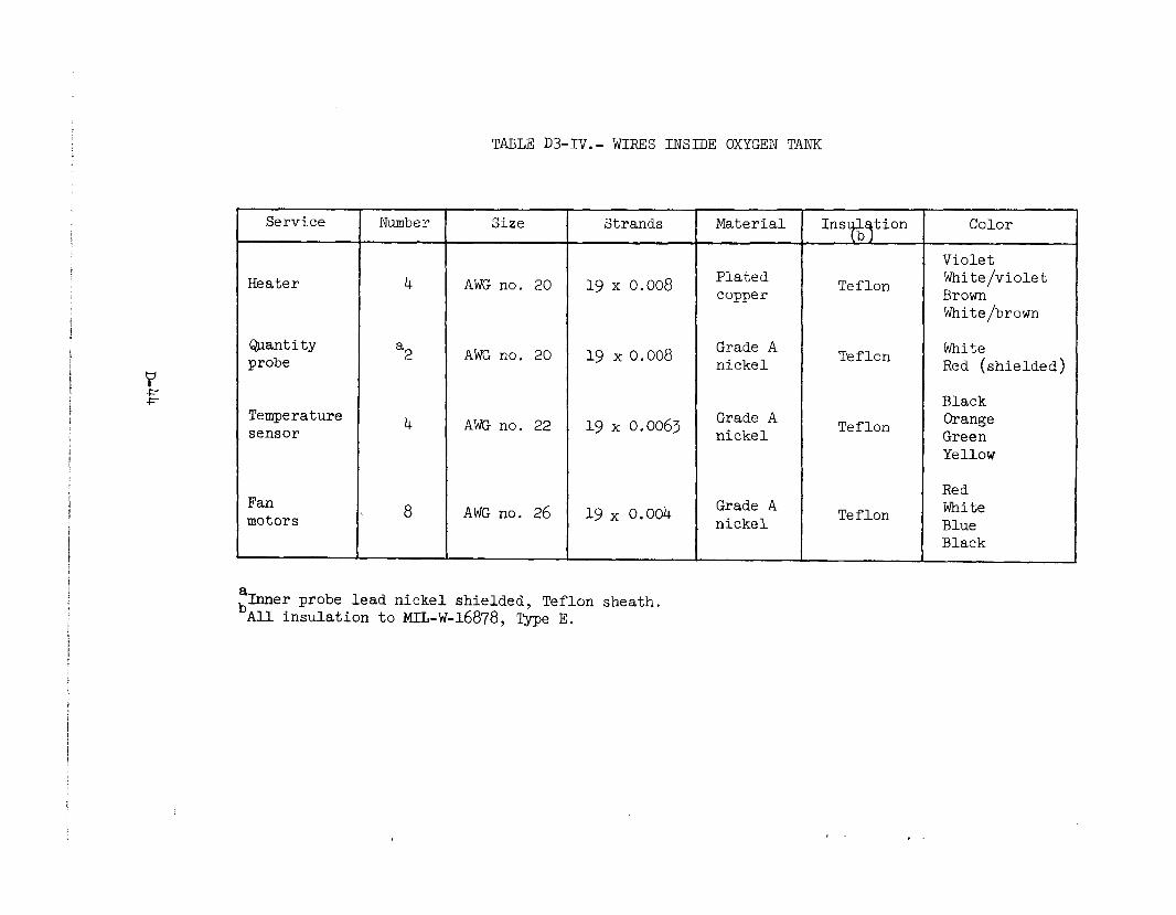
TABLE D3-IV.- WIRES INSIDE OXYGEN TANK
Service Number Size Strands Material Ins tion Color
Violet
Heater 4 AWG no. 20 19 x 0.008 Plated Teflon White/violet copper Brown
White/brown
aantity probe a2
Grade A AWG no. 20 19 x 0.008 nickel
Teflon White Red (shielded)
Temperature sensor
Black
4 AWG no. 22 19 x 0.0063 Grade A Teflon Orange nickel Green
Yellow
Fan motors
Red
8 AWG no. 26 19 x 0.004 Grade A nickel
Teflon White Blue Black
EInner probe lead nickel shielded, Teflon sheath. All insulation to MIL-W-16878, Type E.
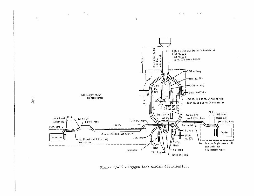
Note: Lengths shown are approximate
Eight no. 26’s plus two no. 14 heat shrink Four no. M’s Four no. 22’s Two no. 20’s (one shielded)
Two no. 20 plus no. 14 heat shrink
Four no. 26 plus no. 14 heat shrink
.38 in. -Two no. 22’s
IH
.OlO tinned
r2 112 in. long copper clip
No. 14 heat shrink 2 in. long I- Marts at ran L ___________
I- Teflon lined clip
L----------l
Four no. 26 plus one no. 14
heat shrink for
2 in. nearest motor
Figure ~3-16. - Oxygen tank wiring distribution.
The mechanical design of the tank with respect to provisions for wiring is considered deficient. Damage to the wiring may be either insulation damage or conductor damage, portions of which cannot be inspected or adequately tested during or after assembly.
The four number 26 AWG wires for the fan motors are encased in 0.012-inch-thick shrink-fit Teflon tubing from the motor housing to a point 0.3 inch outside the heater-fan tube. The 0.012-inch shrink-fit tubing provides the protection for the wires at the point where the four-wire bundle crosses the machined sharp edges of the access hole in the heater tube (fig. D3-17). The shrink-fit tubing does not, however, alleviate the strain on the go-degree bend of the wires at the motor housing. During assembly of the fan to the support tube, the four-wire bundle in the shrink-fit tubing may be forced against the machined sharp edges of the support tube at point “A” of figure D3-17. Two specimens of the support tube that have been examined show no re- moval of burrs at this point. Between the motor and the access hole in the support tube, the wire bundle is restrained by a O.OlO-inch thick soldered copper clip.
The twisted lower fan motor leads (without shrink-fit tubing) reenter the support tube and traverse a 3/16-inch-diameter conduit for 12.0 inches before again exiting the support tube. No specification restraint on slack left in the bundle contained within the heater tube conduit was noted. The motor leads are in contact with the conduit, at least at the ends of the conduit, and exposed to local heat conditions of the heater elements.
Design changes were made between Block I and Block II configurations to provide independent circuits to each motor and heater within the oxygen tanks. Provision was made in the glass-filled Teflon separator on the quantity probe for access of the extra six wires to the upper end of the probe assembly. The conduit (l/2-inch OD x 0.015-inch wall) in the dome for wiring to the connector was not, however, increased in size.
During assembly of the tank, three bundles of six wires each are sequentially pulled through the conduit. The first bundle, consisting of the two quantity gage wires and the four temperature sensor wires, is pulled through the conduit along with the pull wires for the other bundles. The second and third bundles each consist of one set of motor leads encased in 0.012-inch shrink-fit tubing and one set of heater leads. The pull wires have a break-strength of 65 pounds. Since the third bundle of wire must be forceably pulled through the conduit, damage to wires in this bundle or the others may result which may not be detectable without physical inspection. Physical inspection cannot be accomplished with this design.
D-46

Four no. 26 nickel wires
0.218 in.X 0.230 in.
motor lead access (no bushing)
Copper clip
Teflon grommet 9
Fan motor
Figure D3-17.- Typical wire routing for fan motor (four times full size).
D-47
N I

The calculated break strength of a number 26 AWG nickel wire is 11 pounds and elongation of 28 percent can be experienced before break. If the number 26 AWG wires do not share the load associated with pulling the bundle through the conduit, damage to the wire(s) will result be- fore the pull wire breaks. Stretching of the wire results in local neck-down of both the conductor and insulation. In subsequent operation of the circuit, the locally smaller gage conductor can produce local hot spots and progressive deterioration of the insulation.
Discussion
All electrical power system wiring is protected by fuses or circuit breakers specified on the basis of wire size. Such devices will transmit their rated current without opening the circuit to either the load or a fault. The opening of the device to protect the circuit on overload is determined by an inverse time to over-current ratio that will open a large current fault in a short time, and a smaller
over-current fault in a longer time. The protection afforded is to the wire and power system rather than to the connected end item.
The wiring in the oxygen tank has inherent potential for damage in assembly due to inadequate support, inadequate clearances, and thin Teflon insulation. It is well known (refs. 29 and 30) that Teflon in- sulation cold flows when subJect to mechanical stress. The design of the tank internal installation exposes the insulation to potential pro- gressive damage by cold flow where the wiring is placed near or at bends around sharp corners.
.
COMPATIBILITY OF MATERIALS WITH OXYGEN
It is well known that virtually all materials except oxides will react with liquid oxygen (LOX) under specific conditions. The tend- encies to react and the rates of reaction vary widely. Most organic
materials and the more active metals are sufficiently reactive with LOX to require careful attention to the condition under which they are used. Spontaneous reaction does not usually occur upon contact between a material and LOX; however, the sudden application of energy in the form of mechanical shock or electrical spark to the combination of LOX and a chemically active material will often result in violent reaction or rapid burning.
~-48
.-. .-.-^ _-__. -.--, --I.-... ., .__I ,-_____,, .______I __-,. ~,_ __.__ ~. ._--..___-. -II---. I... ^-“---
Classification Methods
.
A method commonly used to classif'y the relative reactivity of materials with LOX is described in references 31 and 32. Based upon this method, a specification, MSFC specification 106B, "Testing Com- patibility of Materials for Liquid Oxygen Systems,U was developed to establish acceptance criteria of materials for use in LOX and gaseous oxygen (GOX) systems. Materials meeting the requirements of paragraph 3.3 of the specification are said to be compatible with LOX. In this context it must be recognized that the term "compatible" describes only the relative reactivity of a material and does not describe an absolute situation.
Materials for use with LOX are selected from the "compatible" list of references 33 to 36 under the additional stipulation that the level of any potential mechanical shock is less than that associated with the impact test and/or that potential electrical energy sources are less than the ignition energy of the material in LOX. If a material is used with oxygen and a potential energy source, it must be determined by test that the energy available is less than that required to initiate the reaction. Furthermore, the test should represent the circumstances of use as nearly as possible.
For example, the pressures and temperatures of the oxygen to which the material will be exposed should be duplicated in the tests. Ad- ditionally, thickness and surface area of the material, as well as that of any backing material (such as may act as a heat sink, for example) should be duplicated. The latter is important because there are ex- amples of materials changing from an acceptable rating to an unaccept- able rating solely because of a change in the thickness used in a par- ticular application. For some proprietary materials and composites whose composition may vary from batch to batch, it is necessary to re- peat the compatibility tests for each batch. Elastomers are a good ex- ample of the latter category. In summary, the methodology for determin- ing compatibility must be adhered to scrupulously to preclude self- deception.
Materials Internal to the Tank
The materials of the internal components of the oxygen pressure vessel have been identified from the records (ref. 37) and assessed as to suitability for use in the high-pressure oxygen environment. The types and estimated quantities of materials in each of these components within the oxygen tank are listed in tables D3-V through D3-IX.
Of the materials used in the tank, most have been subjected previ- ously to compatibility testing in LOX in accordance with the methodology of references 31 and 32.
D-49

TABLE D3-V.- MATERIALS IN HEATBRASSBMBLY
Part name
Tube assembly
Upper and lower motor support
I Silver braze
Wire clamp
Thermostat doubler
Grommet
Shim
Bolts
Screws
Screws
Nuts
Estimated Material weight, lb
321 stainless steel 1.39
302 stainless steel .26
Q&-S-561, Class II .062
Tinned copper .OOl
QQ-A-327 (T6) aluminum alloy .004
Teflon (MIL-P-19462) Negligible
321 stainless steel .06
302 stainless steel .03
302 or 303 stainless steel .04
302 or 304 stainless steel .02
Silver-plated 303 stainless .002 steel
Washers 321 stainless steel .02
Washers 302 stainless steel .007
Rivets 2117 aluminum ,001
Safety wire 304 stainless steel Negligible
Heat shrinkable tubing Teflon (TFE) AWG no. 14 clear ,001 AWG no. 14 white .OOl
Solder 64-S-571, type AR Negligible Camp Sn 60-~b40
Screw Stainless steel pw Q&-S-763 .04
1
D-50
.” ‘...---.. _ ..-- -~ . .-.^-__-” ...-__- “” . ^... ._ ,“-“---“__“-” .-.___l__^ “D ._.. “,“-I,,I___-____III-I-XI~l-__-“_ ,_ __..

TABLE D3-V.- Concluded
Part name
Clamp
Part name I.
Clamp
Drilube 822
Wire Wire
Wire insulation and Wire insulation and shrink fit tubing shrink fit tubing
Disk blank*
Drilube 822
Disk blank*
Stationary contact* Stationary contact* I
Movable arm* Movable arm*
Welding cap* Welding cap*
Insulator* Insulator*
Thrust pin* Thrust pin*
Mounting bracket* Mounting bracket*
Wave washer* Wave washer*
cup* cup*
Rivet contact* Rivet contact* (movable) (movable)
Base assemblyjC Base assemblyjC
1 L L *Thermostat parts *Thermostat parts
Material
Stainless steel clamp with teflon cushion
AWG no. 20, silver-plated copper
Teflon
Bi-metal (21 percent Ni 7 percent Cr Balance Fe and 36 percent Sn)
0.010 fine silver on monel
0.004 Permanickel
Monel
Alsimag 645 or Duco 9p-16
Alsimag 35
302 stainless steel
Stainless steel
321 stainless steel
Fine silver
321 stainless steel base
Estimated weight, lb
Negligible
Negligible
0.0278
.0278
Negligible
Negligible Negligible
Negligible Negligible
Negligible Negligible
Negligible Negligible
Negligible Negligible
Negligible Negligible
Negligible Negligible
Negligible Negligible
Negligible Negligible
Negligible Negligible
1 D-51
_1___-

TABLE D3-VI.- MATERIALS IN DENSITY SENSOR PROBE
Part name Material I Estimated weight, lb
Density sensor/assembly
Bracket
spacer
Rivet
Rivet, solid
:rormnet
;rommet
sleeve
spacer
solder
Cnner tube plug
iivet-semi-tubular
)uter tube
@yelet
?ivet
'erminal
{ivet, solid
jolder
Zleeve, insulator top
3ivet
3003 Al alloy
25% glass-filled TFE Teflon
1100-H-14 Al alloy
2117, 1100 Al alloy
Glass-filled Teflon
Glass-filled Teflon
Red tubing - TFE Teflon Size 9 thin wall
25% glass-filled Teflon
Tin/Lead 60/40
25% glass-filled Teflon
1100-H-14 Al alloy
6063-T832 Al alloy
Brass Comp 22 I-ID QQ-B-626
1100-H-14 Al alloy
Brass 1/2-H Comp. l-QQ-B-613B
110-H-14 or 2117 Al alloy
&Q-S-571 (60/40)
Glass-filled TFE Teflon (25%)
1100-H-14 Al alloy
1.9
.07
.Ol
.Ol
.Ol
.Ol
.Ol
.05
.Ol
.Ol
.03
.Ol
.20
.Ol
.Ol
.Ol
Negligible
.Ol
.4
.Ol
.
D-52

TABLE D3-VI.- Concluded
Part name
ileeve support bottom
Insulator sleeve bottom
{ivet
inner tube
Yerminal coax
Jire
dire, insulation and shrink fit tubing
Material
AMS-5542 Inconel X annealed
Fiber-filled TFE Teflon
1100-H-14 Al alloy
6063-~832 Al alloy
Brass 1/2-H Comp l-QQ-B-613B
AWG no. 20, nickel, grade A
Teflon
Estimated weight, lb
0.025
.4
.Ol
.18
.Ol
.0115
no263
D-53

TABLE D+VII.- MATERIALS IN DENSITY SENSOR PROBE TUBE ASSEMBLY
Part Name
Tube assembly
Sleeve connector
Electrical connector
Solder terminals
Tube
Adapter (fill) upper
Adapter (fill) lower
Estimated Material weight, lb
Inconel X750 1.35
Inconel X750 .1
Inconel X750 .25
Gold-plated Inconel X750 .OOl
Inconel X750 .005
Teflon (TFE) .016
Teflon (TFE) .016

TABLE D3-VIII.- MATERIALS IN FAN MOTORS
Part name
Screw
Plate, end
Shim
Shim
Shim
Bushing, bearing
Bearing, ball
Bearing, ball
Spacer sleeve
Lamination
Insulator, stator slot
Insulator, cell cover
Terminal
Sleeving, heat shrinkable
Compound, insulating
Wire, magnet
Housing
Ring yoke
Material
la-a stainless steel
2024-T4 Al alloy
302 stainless steel
302 stainless steel
302 stainless steel
303 stainless steel
44OC & Rulon "A"
44OC & Rulon "A"
303 stainless steel
Ludnum Al-4750-H no. 2 temp. RL fin.
Teflon impreg. glass cloth
Teflon impreg. glass cloth
Brass 112-H QQ-B-613
Teflon TFE
Liquinite Teflon FBC powder
Teflon overcoated ceramic insulation over copper wire
2024-T4 Al alloy
Transformer grade A silicon electrical steel
Estimated weight, lb
0.02
.04
.02
.02
.02
.04
.02
.02
.lO
.02
.02
.02
.02
.02
.02
.2
.2
.02
D-55
__

TABLE D3-VIII.- Concluded
Part name
Retainer stator
Plate, bearing
Pin, spring
Pin, spring
Insulator
Grommet
Strain relief
Sleeve, rotor
Shim, cover
Plate, front
Vane, impeller
Plate, back
Hub
Lubricant
Safety wire
Wire
Wire insulation and shrink fit tubing
Material
2024-T4 Al alloy
303 stainless steel
302 stainless steel
302 stainless steel
Teflon
Teflon
Teflon impreg. glass cloth
416 stainless steel Q&-5-763
302 stainless steel
3003 aluminum alloy
No. 12 brazing sheet
No. 12 brazing sheet
1100-F aluminum
Drilube no. 822
300 series stainless steel
AWG no. 26, nickel, grade A
Teflon
Estimated weight, lb
0.02
.16
.02
.02
.02
.02
.02
.02
.02
.02
.02
.02
.02
.002
Negligible
.0327
.0518
.
.~_-^-^ - - . _..~ _. . - ~. . . . . _ - . - . - ..__ _L - - . . - . _ . .
_. ._. ls. . . _. . . - . - . - - . - . . . _ ._ - - - -~ “ “ - - -
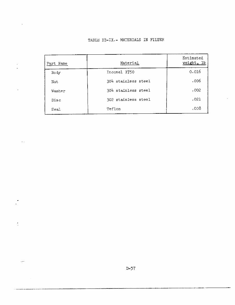
TABLE D3-IX.- MATERIALS IN FILTER
Part Name
BOW
Nut
I Washer Washer
Disc Disc
Seal Seal
Material
Inconel X750
304 stainless steel
304 stainless steel
302 stainless steel
Teflon
.006
.002
.021
.008
D-57
Some of the materials in the tables, however, have a questionable compatibility with LOX, under the criteria of MSFC specification 106B. These are the following:
6C-percent tin, 40-percent lead solder Teflon (TFE) heat shrinkable tubing Drilube 822 Rulon A Colored Teflon Teflon liquinite powder
The solder is listed as incompatible in the references 33 to 36. There are no test results for heat shrinkable Teflon tubing in the references. The last four materials have given inconsistent results in compatibility tests and exemplify the "batch" problem previously discussed. In ad- dition to the above, some of the materials within the sealed thermostats (table D3-V) have apparently not been tested.
It must be emphasized that the data in the references cited are for tests in LOX at relatively low pressures. The compatibility of the ma- terials under the conditions of service in the tank is thus not neces- sarily characterized by the referenced data.
The Teflon insulation used on the wiring within the tank is a prime suspect substance that burned inside Apollo oxygen tank no. 2 (Appen- dix F). Over many years of use, Teflon has been proven to be one of the most satisfactory nonmetallic materials for use in LOX. It will not react with LOX unless excited by energy sources such as extremely high impact energy (above 10 Kg-M) or a spark. Adiabatic compression tests up to pressure of the order of 10 to 12 ksi have failed to ignite Tef- lon. However, additives to Teflon to produce color or other property changes have been known to increase the susceptibility of Teflon to react with LOX.
It must be noted that all oxygen compatibility tests are conducted with the specimens in a scrupulously "LOX-clean" condition. Cleanliness of materials within oxygen systems is vital. Something as innocuous as the oils from a fingerprint can serve as the starting point for a chain of chemical reactions that can lead to a catastrophic failure. For this reason, the same standards of cleanliness employed in compatibility tests must be applied to flight systems.
Although the quantities of incompatible materials may be small, these materials can provide the mechanism for initiating other reactions. For example, in a recent test at MSC, 2 grams of Teflon were ignited in 900 psi oxygen, temperature -190" F, by means of a hot wire. This, in turn, ignited a piece of aluminum 0.006 inch by 0.75 inch by 0.75 inch that was in contact with the Teflon.

Titanium is not listed as a material used in the oxygen system; however, a titanium clamp of the same drawing number, distinguished only by a different dash number, is used in the hydrogen tank. The clamp is made in two halves. The identifying number is stamped on only one half. The titanium halves are matched, drilled, and bagged together at the manufacturers. If a half clamp made of titanium had been placed in- advertently in the oxygen tank, it could have contributed to the fire and subsequent tank failure as the clamp is attached to the boss area of the tank. Because of the bagging and other controls, it is unlikely that a titanium clamp found its way into an oxygen tank. It is poor design practice, however, to have dimensionally identical parts of different materials that may be interchanged and then installed in a potentially hostile environment.
Although not normally exposed to supercritical oxygen, the alum- inized Mylar used in the oxygen tank vacuum annulus, and within the SM, is of interest in the investigation. Aluminized L31ylar is not compatible with oxygen and were the pressure vessel or the tank internal tubing to fail, the Mylar in the annulus and/or the SM would be exposed to con- centrated oxygen. If an ignition source is present, the Mylar would burn. If such burning were to have occured within bay 4, it could have contributed to pressurization of the bay and consequent loss of the SM panel.
OTHER DESIGN AND SYSTEM CONSIDERATIONS
A number of other features and components of the oxygen tank system and of other spacecraft systems are discussed in the following sections.
Oxygen System Relief Valves
The oxygen tank relief valve was designed to protect the oxygen tank against the effects of potential malfunctions of the tank subsystem. Specifically, the valve was designed to relieve a pressure build-up resulting from the worst of the following three system malfunction con- ditions:
1. Heaters on GSE power supply at ground-rated conditions with a full tank and fans running with thermostats failing to open. This yields a heat input of 3002 Btu/hr, which would require a valve flow of 18 lb/hr to prevent exceeding 1010 psig.
2. Heaters on at spacecraft voltage level (28 V dc) and fans running with tank filled such that minimum dQ/dm exists (i.e., most critical condition for raising pressure). This yields a heat input of 685 Btu/hr and a valve flow requirement of 19 lb/hr.
D-59
3. Loss of vacuum in the annulus with the tank filled such that minimum dQ/dm exists. This yields a heat input of 935 Btu/hr which requires a valve flow capacity of 26 lb/hr.
The third condition requires the largest relief valve flow capacity and this was used to size the valve. It was also stipulated that the valve must pass this flow with the fluid at +130° F. These criteria were considered conservative because of the effects of flow through the relief valve on the heat leak, dQ/dm, and system temperatures.
A question arises from an examination of the three malfunction con- ditions assumed: Why Teas the case of heaters powered by ground support equipment (GSE) at critical dQ/dm not considered? Under such a circum- stance, the heat input would be approximately 4-l/2 times that of condition 2 with a flow requirement increase in the same proportion. It was determined that it was not intended to ever use GSE power to the heaters except when the tank was full.
The design philosophy of the relief valve thus contemplated single- failure modes associated with anticipated malfunctions. It did not contemplate a catastrophic failure mode such as would be produced by combustion within the tank. This is not an uncommon design practice in the sizing of relief valves. In ground systems, however, in addition to relief valves , pressure vessels are frequently provided with large burst discs or blowout patches to protect against pressure rises that would result from conditions other than anticipated malfunctions.
The Block II relief valve was subjected to qualification testing as part of an oxygen system valve module qualification test program conducted by Parker Aircraft Company for North American Rockwell (NR) in March of 1967. Reference 38 describes the test program and the results. Briefby, the module, consisting of check valve (for no. 2 tank), relief valve, pressure switch, and pressure transducer, was subjected to the following tests: performance, vacuum, vibration, acceleration, humidity, and endurance cycling. Random vibration excitation was applied for 15 minutes for each axis. The acceleration testing was for 5 minutes in each of the +X, -X, +Y and +Z axes. During both vibration and acceleration tests, the various module elements were operated. The pressurizing medium was nitrogen at rocm temperature during all tests, except for one of the erdurance tests which was conducted at -230° F.
The only discrepancy recorded for the test program was out-of- specification leakage of the check valve subsequent to the vibration test- ing. This was ascribed to the fact that fluid was not flowing through this normally open check valve during vibration which would be its con- dition during flight. This absence of fluid permitted the valve poppet to repeatedly strike the seat causing abnormal wear. Further, there was contamination present in the valve from the flex line used in the test
11-60
. . . . - - - _ .
- -_ , . L,__~” . . - __.” . . - - . . _-- __. . . _c -__., .-___. . - . . - . . -

setup. This aggravated the problem. Because these factors were present, the test conditions were considered not representative of actual service conditions and the check valve performance was considered acceptable (ref. 39). It should be noted that the Block I valve was tested using oxygen as the fluid medium and that the changes from Block I to Block II valves were such as to not invalidate the materials compatibility demon- strated with the Block I systems.
A number of observations are warranted. No shock testing was required for the qualification of the relief valve. In view of the fact that other valves in the service module exhibited shock sensitivity during the Apollo 13 flight and the fact that only a few thousands of an inch of poppet travel is required to open the relief valve fully, it would be valuable to determine whether the relief valve is sensitive to shock. It is possible that the relatively slow decay of oxygen tank no. 1 subsequent to the accident might be the result of a relief valve that failed to seat correctly after the shock.
In the qualification program there was no requirement for the relief valve to vent or relieve into a hard vacuum as it would have to in space. It is possible that under such conditions the oxygen would cool enough to solidify, thus plugging the orifice-like passage of the valve or the downstream lines that lead to the overboard exit, precluding further relieving by the valve. This is particularly important because the exit lines from both relief valves are manifolded prior to entering t'ne overboard line. Were the common line to be plugged by solid oxygen by flow from one valve, it might prevent the second valve from relieving should it be required to do so. An experiment would be required to verify this.
Arrangement at Head of Tank
The head ends of the tank and the temperature sensor and quantity probe are shown in figure D3-18. One of the more significant features of the design is the arrangement of the connections in the fill line which routes the cryogenic fluid to the bottom of the tank, via the inner element of the quantity gage capacitor, and which permit the fluid to flow from the bottom of the tank during ground detanking. The manufacturing drawings of the elements of this connection, two Teflon adapters and an Inconel tube, allow a tolerance stack which is excessive. One combined worst case results in a connection which cannot reach from the fill tube connection in the tank head to the center element of the quantity gage capacitor. The other results in a connection length which prevents assembly of the probe to the adapter in the head of the tank. These are shown in figure D3-19. The tolerances on concentricity between the inner element of the capacitor and the outer shell of the probe are not known and are omitted from this figure. Inclusion would show an even worse situation than shown.
D-61

Vent line and electrical conduit also pass through this adapter
/J
Fill I Feed
Teflon adapter
lnconel tubes
Teflon adapter
.224 S232 dia holes, two
places for heat and motor wirin
I 1 ine -Adapter cap inconel
Figure ~3-18. - Arrangement of head end of tank.
~-62
7 lnconel
1 fl!
I IF-
Temperature sensor and quantity probe -I- I ---
I - -
1 .- .-
Tubular elements of capacitor (aluminum)
Hole for temperature
teflon insulator
Temperature sensor element is mounted on this insulator
~b .-
_ ._ __l._l__.. ._ ~__,, _” .,.,.__ I_ -..-. _ -_--.^._1 ,” ,.,.. .-_. --*I. .c -----.-I . ._.. .-_... -_-.-.-.*--

I I
-----
-
-
-
The experience with the oxygen tank no. 2 in Apollo 13 (apparently normal detanking at Beech, but normal detanking not possible at KSC) suggests that the components used in the fill line connection were close to a worst-case short situation. Tests conducted recently at Beech show that near normal detanking is possible when considerable leakage is present at the joints in the connection, and that a substantial dis- placement of the top Teflon adapter relative to the fill line in the tank adapter cap is necessary to reproduce the KSC situation.
The manufacturing drawing tolerances are such that parts conforming to the drawings could result in an assembly which will not provide the proper connection. However, the probability of a combined worst case is extremely low. It is probable that the actual variations between pro- duction parts are significantly less than the drawing tolerances would permit, particularly the variations between parts within a common batch. Data have been requested on other similar parts to determine whether the variations from part to part are large or small, and whether the average tolerance stack found in practice leads to long or short connection assemblies.
The design is such that the task of assembling the probe to the adapter in the head of the tank (the connection is by four tack welds) is extremely difficult. All wiring must be loosely installed, and the majority of this originates from the fan/heater assembly which must be already installed within the tenk shell. The fill line connection must be steered into place simultaneously with the insertion of the probe into the adapter, and this becomes a blind operation, complicated by the fact that thermal expansion coefficients dictate very sloppy fits between the Teflon adapters and the metal components of the fill line. This problem is dealt with at greater length in Appendix C.
One wey to obviate this problem would be to redesign the internal components of the tank to permit bench assembly and thorough inspection of a single assembly, embodying all internal components and their plumbing and wiring, before introduction into the tank body. It is recognized that a redesign of this magnitude would largely destroy the foundation of experience, both ground and flight, with respect to the operational characteristics of the tank, but it is difficult to see how the internal details of the tank could be modified to provide the necessary degree of post-manufacturing inspectability without abandoning the present side- by-side arrangement of quantity probe and heater,
Dome Assembly
The tank dome assembly (fig. D3-20) form a portion of the outer shell of the tank and houses the fluid lines and electrical conduit connec- ting the inner shell to the exterior of the tank. The upper surface of
~-64
__-. ____ _- -_ .., . x. ..,. _ _- ..r.- “. .” __-.- * . .-._ -“l-...--.-.l. __ ,, I -___. ___. ..“.“.___ “_-,I_” .-,..___ -.- --

,-Dome assembly
Figure D3-20. - Oxygen shelf showing location of tank dome assemblies.
~-65

the dome contains the upper pinch-off tube, through which the annulus is evacuated, and a burst disc (rated at 75 psi ,+ 7.5 psi) that provides burst protection for the outer shell in the event of leakage from the inner shell into the annulus. The arrangement of the fluid lines and electrical conduit within the dome is shown in figures D3-21 and D3-22. The coiling of these lines provides the high impedance path for heat leaks between the inner and outer shells of the tank. In the case of the large diameter vent line, this path is made longer by use of a double-walled tube outside the dome, with connection between inner and outer walls at the extremity of the projection of the tube from the tank.
Tube sizes are listed as follows (all dimensions in inches):
Oxygen Tank Tube Sizing
Vent tube l/2 OD x 0.015 wall (inside coil cover) 3/4 OD x 0.028 wall (outside coil cover) Inconel 750 AMS 5582
Fill tube 3/8 OD x 0.022 wall Inconel 750 AMS 5582
Feed tube* l/4 OD x 0.015 wall Inconel 750 AMS 5582
Electrical tube l/2 OD x 0.015 wall Inconel 750 AMS 5582
Vapor-cooled* 3/1.6 OD x 0.015 wall shield tube Inconel 750 AMS 5582
Pressure vessel to vapor* cooled-shield tube
l/4 OD x 0.015 wall Inconel 750 AMS 5582
*These three tubes are joined sequentially to provide a single feed line which is looped around the tank inner shell to provide regenerative cooling for the vessel.
A total of 18 wires pass through the electrical conduit, eight AWG no. 269, four AWG no. 22's, and six AWG no. 20's. The conduit is shown in figure D3-23. At the start of the investigation some members of the Panel felt that the unorthodox detanking procedure used at KSC could have resulted in unacceptably high temperatures in this electrical conduit due to resistive heating of the heater wires. This possibility is discussed in a later section.
D-66
..- ._.-. “N-m., - ----.- - ..-- -.- .-- -.__ ,- .-... I... -.l-_.l*x,-- II_... I. . . -- -.-.. -. .__~_ ..^.“.-” .__.. ,,.I_______.._ ,.

Feed line7
-Electrical connector
c @
L Vent line
Figure ~3-21.- Arrangement of tubing within tank dome assembly.
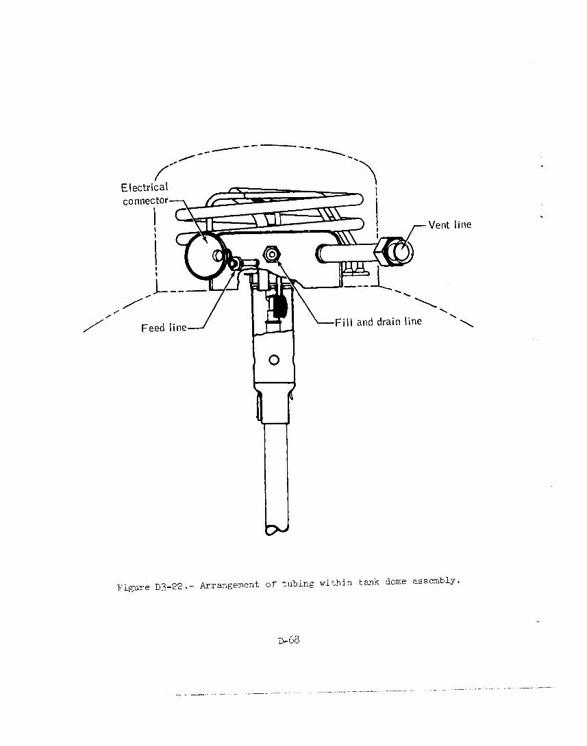
,c- m--w_
-\
f
/
\ \
Fill and drain line ’
Figure ~3-22. - Arrangement of tubing within tank dome assembly.
D-68
.
ine
._. _.-_.._ -. ._l-_l_.-... ..I_ _.. .“--- ._ __. .,.-. _..“_.-_ .~ ---*. ---- -, ____ . ____. ..--. - .__.-- ,.”

m
0000
b0bOb
Figure D3-23.- Arrangement of electrical conduit.
D-69

The design of this portion of the tank results in a configuration in which it is not possible to perform visual inspection of wiring after assembly. In consequence, the possibility of damage, in many cases un- detectable by normal quality assurance procedures, is significant.
Filter
The filter, which is welded onto the supply line projection into the tank, is located within the top of the quantity gage adapter when the tank is assembled. It consists of a series of thin washers stacked on a tube-like mandrel containing relatively large holes communicating with the interior of the t&e. The washers have a series of raised projections on one surface arranged in concentric circles. The projections in each circle are staggered with respect to those adjacent circles. When stacked on the mandrel, the spacing between the washers provided by the projections present a tortuous path for the fluid to traverse in order to enter the center of the mandrel and thus provides a filtering action. The filter is rated at 175 microns and is intended to prevent particles greater than this size from entering the feed line.
The filter is of simple and reliable construction, and should provide only very small restriction to flow out of the tank. In the application, the two components protected by the filter are the relief valve and the check valve in the tank no. 2 valve module, both of which have moving poppets that must seat properly in order not to leak.
In normal circumstances the filter location is appropriate. Under abnormal circumstances, such as the combustion in tank no. 2 experienced on Apollo 13, the filter might become clogged with solid combustion products and thus preclude flow to the relief valves. Considering its construction, and ample flow area, this is not very probable. Tests are to be conducted to verify this.
Caution and Warning Provisions
Because of their design, the caution and warning system and the switch-controlled indicators ("talkbacks") did not present correct systems status to the crew during the Apollo 13 accident. As described in Appendix B, the following items are noted as examples:
1. The loss of oxygen to fuel cells 1 and 3 occasioned by closure of the oxygen shutoff valves was not indicated. The series logic used in the information system required that both the hydrogen shutoff valve and the oxygen shutoff valve be closed to activate the warning system. Simultaneous operation of the valves is appropriate to a deliberate shutdown of a fuel cell which should require no warning indication.
D-70
_ -.-..“- .-- -_ _. . - ,,.._._.____ .._- .- . ..“__... . . .--.. ._ll-_,-.-- -
.~ .-_^ ..-._ ,__- _ _L. -- rl , ._*,. - -- - .“*-_- “- .., . --- .-- ---- .~-, --.

2. The crew was not alerted to the abnormal rise and subsequent loss of oxygen pressure in tank no. 2 because a normal out-of-limits operational signal (low hydrogen pressure) was in existence.
3. When power was lost to main bus B, the VtalkbackV indicators designed to indicate the state of RCS valves were no longer energized and could not properly indicate valve position.
Thus, accurate information as to the state of spacecraft systems, which is vital in time of emergency, was not provided by the caution and warning system.
ABNORMAL EVENTS IN THE HISTORY OF THE OXYGEN TANK
The oxygen tank which failed during the Apollo 13 mission had been subjected to two abnormal incidents prior to launch. The first occurred during spacecraft assembly. The oxygen shelf was "dropped" and the tank subjected to a shock load. The second abnormal condition occurred at KSC. An unorthodox detanking technique was used when the tank failed to empty during the normal procedures. The possible consequences of those incidents are discussed in the following sections.
Oxygen "Shelf Drop" Incident
The oxygen shelf which flew in Apollo 13 (Spacecraft 109) orig- inally was installed in Spacecraft 106. On October 21, 1968, this shelf was in process of being removed from Spacecraft 106 for a rework of the vat-ion pumps. During the removal, the sling adapter (ground equipment) broke. The cause for the failure was traced to failure to remove one of the bolts attaching the shelf to the service module, At the time of the incident, it was assumed that the failure permitted the shelf outboard edge to fall back about 2 inches, at which point the shelf motion was stopped by the supports in the service module. An analysis of the stiff- ness of the oxygen shelf led to the prediction of a shock load of the order of log. The incident is reported in mere detail in Appendix C. An analysis of the incident is contained in the files of the Board. The general con&-usions are as follows:
1. The Apollo 13 oxygen "shelf drop" incident can be explained by assuming that the counterbalance weights on the 9EH-1275-100 sling were run out in an attempt to "balance" the effect of the shelf attach bolt (which was inadvertently not removed) to a point at which they caused the sling adapter to fail in bending.
D-71
2. The geometry and loading of the system at the time of failure would rotate the oxygen shelf about the remaining shelf attach bolt un- til the top of oxygen tank no. 2 impacted the underside of the fuel cell shelf, causing the observed dent in the shelf.
3. Tests to reproduce the dent in the fuel cell shelf have been conducted by striking a specimen o f the shelf aluminum honeycomb ma- terial with an appropriately weighted tank pinch-off tube cover. The test results indicate that in order to XepXOdUCe the observed dent, a maximum acceleration of 7g was required.
4. On the basis of these data, it does not appear that the loads transmitted to the internal components of the tank during the "shelf drop" incident were of sufficient magnitude to cause any structural failure. One possible effect, however, could have been the displacement of a marginally secured connection between the fill line and the inner element of the quantity gage capacitor. Should this have occurred, it could have been the cause of the detanking anomaly experienced at KSC with oxygen tank no. 2 during the preflight operations on Apollo 13.
Detanking at KSC
The difficulty with the detanking of oxygen tank no. 2 subsequent to the countdown demonstration test (CDDT) is described in Appendix C. As noted in the preceding section, the inability to detank may be as- cribed to a displacement of the short Inconel tube in that portion of the fill line located in the top of the quantity probe or the absence of this tube. Tests conducted at Beech Aircraft Corporation subsequent to the flight have demonstrated that if the tube is displaced laterally about 0.090 inch from its mating Teflon adapter, it is not possible to detank in normal fashion. The manufacturing tolerances for this sub- assembly have been discussed previously, and it is apparent that it is possible for such a displacement to occur if the parts are at appropriate extremes of the tolerances.
The nonstandard procedure used to detank oxygen tank no. 2 involved continuous power application to the heaters at GSE power supply voltage for 8 hours an3 10 minutes. The fans were operated for all but the first hour and 20 minutes of this period. There is no conclusive evi- dence that either of the thermostats ever operated to open the heater circuits during this period. This occurred, despite the fact that the tank temperature sensor out-put, indicating ullage space temperature under the conditions of this procedure, was still rising when the instru- ment reached its readout limit of 84" F.
During this detanking, the C-SE power supply was providing approxi- mately 6.0 amperes to each of the two heaters at approximately 65 V dc
D-72
at the spacecraft. Tests conducted at MSC subsequent to the flight showed that when a thermostat attempted to interrupt a 6.0-ampere current at 65 V dc, the contacts welded shut. Whereas such contacts are rated by the manufacturer to interrupt at least a 6-ampere alter- nating current, under direct current conditions a considerable arc will be drawn and welding of the contacts will frequently result. At the time of this writing, three thermostats have been tested under voltage and current conditions like those experienced during the nonstandard detanking. All three failed by welding closed. Were the contacts in oxygen tank no. 2 thermostats to have failed in this manner, which seems highly probable, the heaters would have drawn current for the total period that the circuits were energized. There are a number of possible consequences of this condition. These are discussed in the following paragraphs.
Because the wiring in the conduit in the tank dome is of relatively small diameter for the current carried, it might lead to excessive wire temperatures by resistance heating, as this conduit represents a stagnant region with poor heat paths for removal of the heat generated. Were the temperatures to rise sufficiently, it could degrade the insulation to the point that the wire might be exposed. Preliminary calculations in- dicated that the temperature of the wires might rise to the point of in- sulation degradation and/or melting of soldered connections. A pre- liminary test using an actual conduit has indicated the temperature would not rise above about 325" F, which is well below the threshold temperature for wire insulation and solder damage. More definitive data on this possibility will be provided by a test planned for the near future at Beech Aircraft Corporation. A flight-type tank will be sub- jected to a reproduction of the nonstandard detanking process to deter- mine, among other things, how hot the wiring in the conduit would get.
The second possible mode for damaging the wiring during the de- tanking is related to the pressure pulsing employed during the latter part of the detanking operation. When the tank is pressurized and quickly vented, the cryogenic oxygen will boil violently, probably pro- ducing "slugging" or "geysering" at the liquid-vapor interface. This action could easily flex the large unsupported loop of wire that results from the assembly process and thus could induce mechanical damage to the wire. This, too, must be confirmed by test before it can be considered as more than a possibility.
The third possibility for inducing wire damage applies primarily to the wiring in proximity to the heaters-- especially the fan motor leads that are routed through the 12 inches of 3/16-inch diameter conduit that runs internal to the heater probe (see fig. ~3-16). If the thermostat contacts failed by welding closed, as seems probable from the results of the thermostat tests described earlier, the heater probe metal tempera- tures would continue to rise, limited only by the heat balance between
D-73
that being generated by the heater and that being absorbed by the liquid and gaseous oxygen in the tank. Were the heater probe temperatures to rise above about 500" F, the wire insulation in its proximity would begin to degrade.
A test simulating prolonged application of power to heaters and fans with a heater probe half immersed in liquid nitrogen at one atmos- phere pressure was conducted at MSC. After 8 hours, a thermocouple mounted directly on the outer casing of a heater element at a location where it was in contact only with the gaseous nitrogen in the ullage indicated a surface temperature of about 1000" F. At the same time, the temperature of the conduit wall reached 735" F.
Posttest inspection of the wiring indicated that the insulation had been seriously degraded (fig. D3-24). The insulation had become rela- tively brittle and had cracked in numerous places. Upon any subsequent flexing of the wire, the insulation would either break off or shift to widen the cracks, in either case exposing the conductor. Such an ex- posure would set the stage for a future short circuit. The state and nature of the degradation of the insulation depends on the temperature it reaches. It should be noted that this test was conducted in a nitro- gen atmosphere, whereas the actual prolonged heater operation occurred in an oxygen environment. An oxygen environment is less benign chemi- cally than one of nitrogen, and greater degradation than that observed might occur. The all-up test at Beech s'hould provide more definitive information on this matter.
In summary, the nonstandard detanking procedure probably provided the mechanism for initiating the flight failure by causing sufficient damage to wire insulation to expose the conductor(s) of the fan motor leads. This would permit a short circuit to occur and initiate com- bustion within the tank. It is also possible that some solder was melted during the prolonged heating. Under the normal gravity conditions on the launch stand, it would be possible for a drop(s) of solder to fall free and solidify and remain in the tank. This could possibly lead to the subsequent shorting of the capacitor gage.
Discussion
As described in the preceding sections, the design of the oxygen tank as a pressure vessel is very adequa,te. It is constructed of a tough material well chosen for the application. There is no evidence of substandard manufacture of the particular tank involved, nor has any evidence been found of subsequent damage that would result in degrada- tion of the structural integrity of the pressure vessel (as distinguished from the internal components of the tank).
D-74

D-75
If the telemetered pressure data truly represent the pressure the tank experienced at the time of the accident, it should not have failed structurally. The qualification burst test results indicate that the pressure vessel is capable of withstanding over twice the maximum pres- sure indicated at the temperatures recorded. The tubing is capable of withstanding even greater loads.
There was, as described in Appendix B, an observed abnormal in- crease in pressure and temperature in the tank. As has been discussed previously, there are combustibles, both metallic and nonmetallic, within the tank, as well as potential energy sources to provide ignition, es- pecially of the Teflon insulation of the internal wiring. The method of assembling the tank system and the details of construction of the tank's internal components provide an opportunity for wiring damage. Also, there is an even greater probability that, in this instance, the non- standard detanking process created bare conductors. With such damaged wiring, a mechanism for creating a spark is provided and a consequence would be a fire within the confines of the tank. This would result in increases in the pressure and temperature within the tank.
There is sufficient Teflon within the tank to cause the internal pressure to rise above the burst strength of the pressure vessel were it all to be consumed. However, the locations of the Teflon components are such that igniting all of them is not very probable. The energy available from the combustionTthe aluminum within the tank also exceeds that required to burst the tank. Tests conducted during the investigation indicate that enough electrical energy was available to initiate a combustion process within the tank under electrical fault conditions (Appendix F).
Among the possible ways that the tank integrity could have been lost, two are worthy of special mention. First, should combustion have existed within the electrical conduit, a relatively stagnant region with an intentionally poor heat conduction path, the conduit walls would have been heated quite rapidly. The conduit contains the greatest concentra- tion of wiring and wire insulation within the tank. It was estimated that raising the conduit temperature to about 1500' F under the pressures prevailing during flight would cause the conduit walls to fail. This has subsequently been demonstrated in a test at MSC wherein the wiring insulation in an actual conduit was intentionally ignited under conditions simulating the conduit environment within the tank. In this test, local heating caused the conduit to fail a short time after initiation of combustion within the conduit. Such a failure would result in pressuriza- tion of the tank vacuum dome, leading to actuation of the blowout patch and loss of oxygen tank pressure.
D-76
The second possibility is ass ociated with the reaction of aluminum with oxygen. This process has been described as quite violent (see Appendix F). Were the aluminum to have been ignited and if its reaction rate under the conditions within the tank were sufficiently high, the pressure could rise very rapidly and lead to pressure vessel failure at burst pressure levels. Such a pressure rise might not have been evidenced in the data because of the low sampling rate of the pressure sensor telemetry signal. Tests are required to verify this hypothesis.
A nmber of observations were made during the course of the Panel's activities that gave rise to further questions. It is recognized that many of these matters al-e of a subjective nature. Nonetheless, they are considered worthy of comment in this report.
Oxygen tank no. 1 lost pressure subsequent to the failure of tank no. 2. The mechanism of damage to tank no. 1 has not been established. It is assumed to be the result of a line or valve failure in the tank no. l system. The two tsnks and their associated hardware represent, to a large degree, redundant systems. They are, however, in great part colocated. For exmple, t'ne tanks are adjacent to one another, the system valves are grouped in a common housing, the fluid lines and wiring are routed parallel to one another in close proximity. Systems other than the oxygen subsystems have similar configurations. Such practice provides the possibility of inducing failure in a redundant system by a failure of its companion. This is a most. complex subject and difficult to assess. It is also recognized that much of the hardware for Apollo has already been built. There appears to be a need for a review and evaluation of this matter.
No evidence has been found that indicates that shock testing of components and/or subsystem assemblies is a normal qualification require- ment for Apollo service module hardware. The flight environment contains shocks of a considerab.le magnitude during events such as staging of the launch vehicle. That the effects of such environments on system components were recogni.zed is evidenced by the use of holding current on the fuel cell reactant shutoff valves, for example. Shocks can be applied to hardware during shipment and normal handling, even though elaborate precautions in the form of special shipping containers, labels, and cautionary tags to alert transportation groups to the sensitivity of the shipment are employed. Good design and development practice includes experimental determination of margins against damage under such circum- stances. Again, there appears to be a need for a review and evaluation of the susceptibility of the components in the spacecraft to all credible shock levels they may encounter in their service life so that the margins of safety inherent in their design may be established.
RELATED SYSTENS
As a result of the Apollo i3 accident, a critical examination of other Apollo systems is being conducted by MSC to insure that the potential for a similar mode of failure does not exist elsewhere in the spacecraft. A member of the Design Panel was present at the MSC review meetings. The following is a summary of the activity and a status of the MSC effort.
The review was limited to selected systems in the following major Apollo elements:
Command and service module
Ascent and descent stage of the lunar module
Gcvernment furnished equipment
Gro*und support equipment
As an aid in determining which subsystems should be reviewed, a tabniation of all pressure vessels in these major elements was assembled (table D3-X). The cryogenic oxygen tank, which is reviewed in earlier sections of this report, was excluded from this review. Table D3-XI lists those systems and major elements that were selected for review. All vessels and oxygen and propellant line components in the selected systems are to be analyzed. The primary emphasis during the review is on the oxygen and oxidizer systems and the identification of all sources cf energy-- bot,h i.nt,ernal and external to the system--that could result in an excessive pressure rise and possibly res-ult in the failure or degradation of a system. Sources of energy which were considered were electrical, mechacicai, and solar.
Pressure Vessels
The pressure vessels are of concern in that they represent lagge energy sources in the event of their catastrophic failure. Qualification records were reviewed and analyzed to determine the actual factors of safety demonstrated by burst t.est, as well as the characteristics of the failure modes. The failure modes of the pressure vessels have been cate- gorized as explosive, uncertain, andbenign. With these data, an assess- ment was made of those components that might be damaged by the explosion of a tank and the effect of this explosion on the vehicle systems and the crew.
~-78
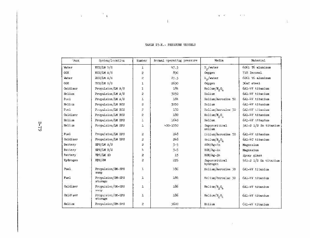
TABLE 03-X.- PRESSURE VESSELS
Tank
Water
GOX
Water
GOX
Oxidizer
Helium
Fuel
Helium
Fuel
Oxidizer
Helium
Helium
Fuel
Oxidizer
Battery
Battery
Battery
Hydrogen
Fuel
Fuel
Oxidizer
Oxidizer
Helium
System/location
ECS/LM D/S
ECS/IM A/S
ECS/LM A/S
ECS/LM D/S
Propulsion/IM A/S
Propulsion/LM A/S
Propulsion/U% A/S
Propulsion/LM RCS
Propulsion/IM RCS
Propulsion/LM RCS
Propulsion/LM DPS
Propulsion/LM DPS
Propulsion/l&l DPS
Propulsion/l&f DPS
EPS/LM A/S
EPS/LM D/S
EPS/LM ED
EPS/SM
Propulsion/SM-SPS Sump
Propulsion/SM-SPS storage
Propulsion/SM-SPS sump
Propulsion/SM-SPS storage
Propulsion/SM-SPS
Number
1
2
2
1
1
2
1
2
2
2
1
1
2
2
2
4
2
2
1
1
1
1
2
Normal operating pressure
47.3
890
27.3
2690
la4
3050
184
3050
180
180
1640
400-1550
248
248
3-5
3-5
15
225
186
186
186
186
3600
Media
N2/water
Oxygen
N2/water
@wren
Helium/N204
Helium
Helium/Aerozine 50
Helium
Helium/Aerozine 50
Helium/N204
Helium
Supercritical helium
Helium/Aerozine 50
Helium/N204
KOH/Ag-Zn
KOH/Ag-Zn
KOH/Ag-Zn
Supercritical hydrogen
Helium/Aerozine 50
Helium/Aerozine 50
Helium/N204
Helium/N204
Helium
Material
6061 T6 aluminum
718 Inconel
6061 T6 aluminum
D6aC steel
6Al-4~ titanium
6~1-4~ titanium
6~1-4~ titanium
6~1-4~ titanium
6~1-4~ titanium
6~1-4~ titanium
6~1-4~ titanium
5A1-2 l/2 Sn titanium
6~1-4~ titanium
6m-4~ titanium
Magnesium
Magnesium
Epoxy glass
5Al-2 l/2 Sn titanium
~AI.-4~ titanium
6~1-4~ titanium
6Al-4~ titanium
6~1-4~ titanium
6~1-4~ titanium
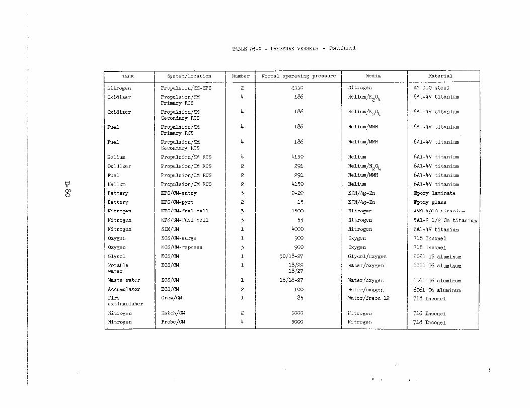
TABLE D3-X.- PRESSURE VESSELS - Continued
Tank System/location Number Normal operating pressure Media Material
Nitrogen Propulsion/SM-SPS 2 2350 Nitrogen AM 350 steel
Oxidizer Propulsion/SM 4 186 6Al-4~ titanium Primary RCS
Helium/N204
Oxidizer Propulsion/SM 4 186 Helium/N204 6Al-4~ titanium Secondary RCS
Fuel Propulsion/SM 4 186 Helium/MMH 6~1-4~ titanium Primary RCS
Fuel Propulsion/SM 4 186 Helium/MMH 6Al-4~ titanium Secondary RCS
Helium Propulsion/m RCS 4 4150 Helium 6~1-4~ titanium
Oxidizer Propulsion/CM RCS 2 291 Helium/N204 6Ai-4~ titanium
Fuel Propulsion/CM RCS 2 291 Helium/MMH 6Al-4~ titanium
Helium Propulsion/CM RCS 2 4150 Helium 6~1-4~ titanium
Battery EPS/CM-entry 3 O-20 KOH/Ag-Zn Epoxy laminate
Battery EPS/CM-pyro 2 15 KOH/Ag-Zn Epoxy glass
Nitrogen EPS/SM-fuel cell 3 1500 Nitrogen AMS 4910 titanium
Nitrogen EPS/SM-fuel cell 3 53 Nitrogen 5Al-2 l/2 Sn titaniun
Nitrogen SIM/SM 1 4000 Nitrogen 6Al-4~ titanium
@awn ECS/CM-surge 1 900 W-gen 718 Inconel
oxygen ECS/CM-repress 3 900 @wren 718 Inconel
Glycol ECS/CM 1 50/18-27 Glycol/oxygen 6061 T6 aluminum
Potable ECS/CM 1 la/22 la/27
Water/oxygen 6061 T6 aluminum water
Waste water ECS/CM 1 18/18-27 Water/oxygen 6061 ~6 aluminum
Accumulator ECS/CM 2 100 Water/oxygen 6061 ~6 aluminum
Fire Crew/CM 1 a5 Water/freon 12 718 Inconel extinguisher
Nitrogen Hatch/CM 2 5000 Nitrogen 718 Inconel
Nitrogen Probe/CM 4 5000 Nitrogen 718 Inconel

TABLE Dj-X.- PRESSURE VESSELS - Concluded
Tank System/location Number Normal operating pressure Media Material
Wren PLSS 1 1020 Wwn 301 cryoform
Water PLSS 1 3.8 Water/oxygen 6061 T6 aluminum
Battery PLSS 1 5-a KOH/Ag-Zn Titanium
Oxygen OPS 2 5880 Oxygen 718 Inconel
Carbon dioxide Raft 2 1000 co2 301 cryoform
Carbon dioxide Life vest 2 1000 co2
Steel
@w@;en PAD pack 5 3600 CWwn 301 cryoform
Helium Snap 27 fuel capsule 1 4-700 Helium Haines 25
Helium/ Seismic experiment 1 333 10% helium AM 347 nitrogen 90% nitrogen
Air Crew/LGEC camera 1 500 Air 6061 T6 aluminum
Hydrogen GSE/KSC 1 20 Liquid hydrogen 6061 T6 aluminum
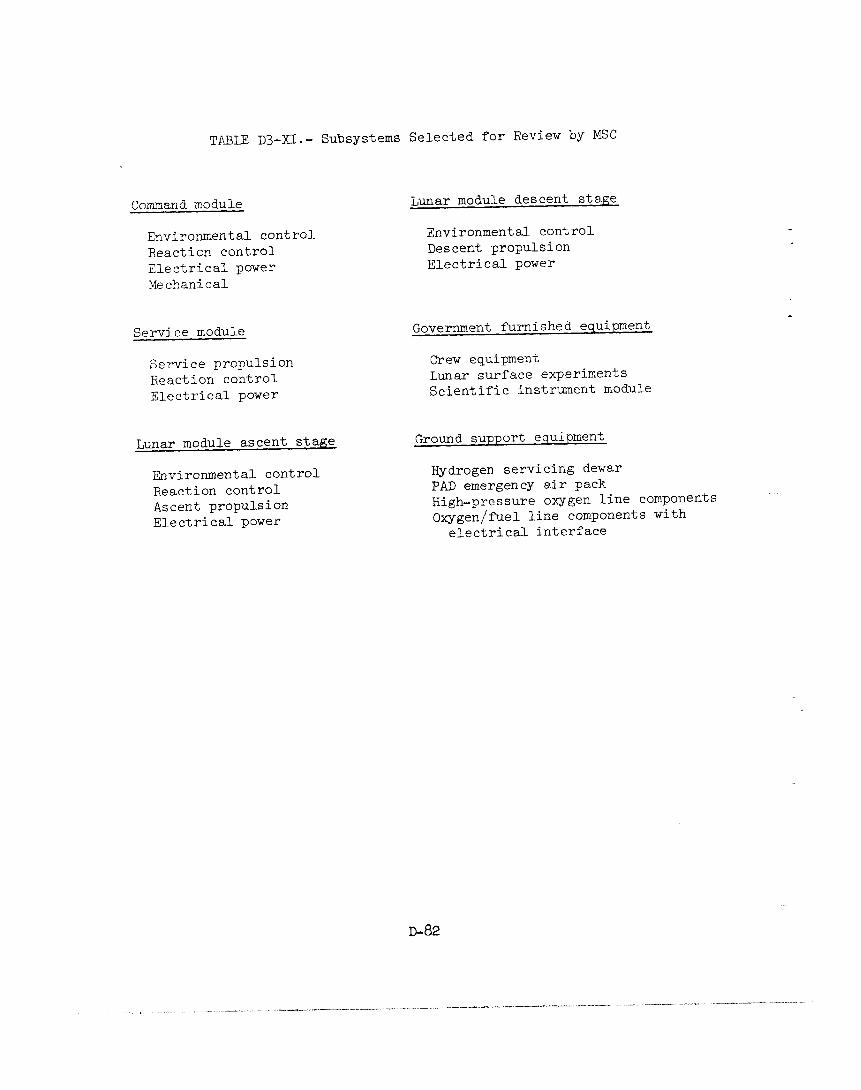
TABLE D+XI.- Subsystems Selected for Review by MSC
Command module
Environmental control Reaction control Electrical power Mechanical
Service module
Service propulsion Reaction control Electrical power
Lunar module ascent stage
Environmental control Reaction control Ascent propulsion Electrical power
Lunar module descent stage
Environmental control Descent propulsion Electrical power
Government furnished equipment
Crew equipment Lunar surface experiments Scientific instrument module
Ground support eqUipIUent
Hydrogen servicing dewar PAD emergency air pack High-pressure oxygen line components Oxygen/fuel line components with
electrical interface
.___ ._,I - -_-_ -_-~..- _ I_“_ ._ ,^-ll-l_ll.-.--.---- ----- -, ,_- _.. “-~ .-
____ II .._-._._ ..- ____ _..__I., “_I -- .
The explosive failure of a pressure vessel on the spacecraft, depend- ing upon the energy stored in the vessel, could result in effects ranging from localized damage to loss of spacecraft and crew.
The following approaches were considered to provide protection to the spacecraft and crew from the catastrophic explosion of a major pressure vessel:
1. Isolation of the pressure vessel by separation.
2. Controlled failure provisions by changes to the vent or relief system to permit rapid depressurization.
3. Containing the blast by the addition of shielding by heavier or strengthened walls.
It was concluded that it would be theoretically possible to provide increased, but not total, protection for the spacecraft against the catastrophic explosive failure of a pressure vessel if major vehicular and pressure vessel changes were made. There are many practical limita- tions which preclude the provision of total protection against the cat- astrophic explosive failure of a pressure vessel. To determine the effect on the spacecraft of a nonexplosive or a benign leakage-type failure of a pressure vessel, the components and materials in the im- mediate vicinity of the tank in question were identified. Both the LM and CSM have nonmetallic materials which probably would not survive if they were exposed to propellants as the result of a pressure vessel failure. It is not feasible to use materials throughout the spacecraft which are totally compatible with all fluids that they could encounter following a primary failure. Considering the vehicle and systems effects of a pressure vessel failure (leakage or explosive), it is clear that neither containment nor complete nonmetallic material compatibility can be provided in the form of practical or reasonable solutions for space- craft and crew protection against all tank failures. A tank failure would result in at least the abort of a mission, even through the damage from a pressure vessel could be contained.
The review of the pressure vessels of table D3-X identified a direct electrical interface or exposed wiring in the media as follows:
Propellant quantity gaging systems in the lunar module descent stage’Canks and in the service module service propulsion system (SPS) tanks.
2. Capacitance gage, heaters, motors, and temperature sensor in the cryogenic hydrogen tanks in the service module.

3. Quantity gage in the potable and waste water tanks in the command module.
4 . Quantity sensing gage in the GSE hydrogen dewar.
The MSC is conducting an analysis and plans to perform tests on the quantity gaging systems to insure that the combination of fuel and energy potential for ignition are understood and represent no hazard. Associated with this is a review of the circuitry and circuit protection. The waste and potable water tanks are being reviewed to determine the hazards, if any, of the electrical circuit and the advisability of de- leting the quantity gage.
The cryogenic hydrogen gas pressure vessel was reviewed and it was verified that the manufacturing and assembly techniques, as well as the arrangement of the internal components, are very similar to those of the oxygen tank. The same -potential for an electrical malfunction in the hydrogen tank exists as did in the oxygen tank. Mission rules have been reviewed and it was determined that the minimum failure in a hydro- gen tank which would result in a mission abort would be the loss of two heaters and cne fan. The MSC is planning to conduct tests to determine if an electrical malfunction can induce a sustained reaction between hydrogen and materials contained within the tank. Tests will also be conducted to determine if both heaters would fail following an electrical malfunction. Structural and materials compatibility analysis and re- views indicate that the titanium alloy (5 Al, 2-l/2 Sn) as used does not experience hydrogen embrittlement.
The remaining pressure vessels were reviewed to determine those that had internal components, which could expose an electrical interface to the contained media following a single failure. In addition, the non- metallics that might be exposed following such a single failure are being identified to insure that they are compatible with the media at operating conditions.
The review of the LM pressurized tanks disclosed that helium and oxygen tanks are isolated from their relief valves during the translunar coast period. Under normal flight conditions at ambient temperatures the pressure rise in the tanks is relatively insignificant. If protec- tive thermal blankets on the LM should be lost or damaged, the pressure rise could be significant. A Grumman study indicates that if the com- plete loss of thermal blankets occurred in the areas of the following tanks they could reach burst pressures during translunar Coast:
Ascent stage oxygen
Ascent propulsion system helium
~-84
--.. ._ x -_.--. “.. _. -... “..” FI.” ^.ll_..I ..--. - -.-... _ _ . .._-. ._ -..
.-.1_^ . ^_.-_.I^^ _._.___ --.,-._,.
Reaction control system helium
Descent propulsion system helium
Loss or damage of a thermal blanket could probably be determined during transposition and docking on all except the descent helium tank. It should be noted that no rational failure mode has been identi- fied which could result in the loss or damage of a thermal blanket.
Line Components
The line components that are integral to the systems in table D3-XI are also being examined to determine those with and those without an electrical interface. The electrical interfaces are of two types, direct exposure to the media and exposure following a single failure. In addition, all nonmetallics near a potential ignition source will be identified and evaluated.
The only component which has been identified as of this date as having nonmetallics and a direct electrical interface in high-pressure oxygen is the fuel cell reactant shutoff valve. The Teflon-coated wires internal to this valve, when energized, carry steady-state currents of 2 amperes and transients of 10 amperes in a 900 psi oxygen environment. The circuit protection consists of a lo-ampere circuit breaker. During the launch and boost phase, a current limited circuit, approximately 0.5 ampere at 9 to 10 volts, is applied to the Iropen" coil to insure that the valve remains in the open position. The valve position sensor switch, which is also internal, is continuously energized during the entire mission from a 28-volt circuit protected by a lo-ampere breaker. This valve is now the subject of an intensive review by MSC and the contractor. There is no indication that this reactant valve had any internal malfunction during the Apollo 13 accident other than the shock closure.
Components without direct electrical interfaces are also being examined to identify those in which nonmetallic materials are normally exposed to the media and those in which nonmetallic materials could be exposed following a single failure. To determine the probability of a single failure in static components such as temperature and pressure transducers, the acceptance and certification testing of critical elements is being reviewed. It has been ascertained that component elements such as bellows, probe cases, and internal diaphragms are designed and tested for pressure levels far in excess of system usage. The reliability reports confirmed that leakage failure of these elements has not occurred on Apollo flight hardware.
D-85

In addition to normal material compatibility determinations, those components which have nonmetallics used in impact applications are being identified and it is planned that, where necessary, additional testing will be conducted in the media at appropriate operating conditions to determine that there are no impact-sensitive applications.
Low Pressure Oxygen Systems
Following the Apollo 204 accident, the metallic and nonmetallic materials in the cabin of both the command module and lunar module were subjected to an intensive review. As a result of the research and testing, the materials within the LM and CM were modified or changed to reduce the probability of an ignition and to minimize the combustion or propagation of fire in the cabin. Considering the redesign that was accomplished and the continuing rigorous control of materials added to the spacecraft cabins, the low-pressure oxygen systems (less than 25 psi) were not reevaluated during this current investigation by MSC.
Electrical Power System--Batteries
Both the IX and the CSM use the same type battery to initiate the pyrotechnic functions. A review of the records indicated that the G-10 laminated glass epox;y battery case had not been qualified as a pressure vessel. The case is protected by a relief valve which operates at 30 + 5 psi. In the event of a relief valve failure, and case pressuriza- tion to rupture, potassium hydroxide could be released. A certification program will be conducted to establish the strength of this battery case and procedures established for the acceptance proof testing on all flight batteries prior to each mission.
Ground Support Equipment
This review is structured to identify all pressure vessels and line components in propellant and high-pressure oxygen systems with direct electrical interfaces and the associated metallic and nonmetallic materials. All high-pressure oxygen, gaseous and liquid, valve seat material will be identified as well as any other application of nonmetallic material in an impact loading application. This MSC review is limited
to equipment supplied by North American Rockwell and Grumman.
During the review of the GSE, it was also established that cleaning and filtering techniques used have been generally effective in limiting contamination. Shock-sensitive materials have been detected in the liquid hydrogen dewar in small quantities (less than 1 mg/liter), which are within specification limits for nonvolatile residuals. The source
D-86
. I~ .
. . _ . . -_.-_ . _ . . - . ~^, I __--” _ _ ._“_” - . . .

--
and quantity of the shock-sensitive materials should be identified, as well as the potential for a buildup in concentration. It is recognized that contamination is not considered as a candidate cause for the Apollo 13 accident.
Certification
The certification records for al.1 pressure vessels and components of the subsystems that were considered have been reexamined during this MSC review. It was established that all certification requirements were adequately met, that all discrepancies were adequately explained, and that all components were qualified for flight. It should be noted that a ccunparison of the certification requirements with the expected flight and ground environment was not part of this review.
Apollo J-Missions
Both the CSM and I&l systems are being modified to support the extended lunar stay time and lunar orbit experiments for later Apollo missions. The MSC review included the nitrogen bottle being added to the scientific instrument module of the service module for the Pan camera. The other system changes and additions to the L&l and CSM for the J-Mission consist of the addition of more pressure vessels and components of the types already installed in the spacecraft and examined during this review. No new pressure vessels or components are planned.
Lunar Module "Lifeboat"
Associated with the Related Systems Review, MSC is also analyzing how the "lifeboat" capability of the IM could be enhanced. The LM, CSM, and PLSSiUPS are being reviewed to determine what minor modifications to the concerned systems and/or changes in procedures should be incor- porated. The intent of the changes would be to enhance the ability of the crew to interchange or transfer oxygen, water, electrical power, and lithium hydroxide cannisters between spacecraft and to increase the probability of crew survival following multiple failures in the command module.
DISCUSSION
As a result of the MSC Related Systems Reviews that have been completed and are still in progress, the following observations are offered.
D-87

A fracture mechanics analysis was made of all Saturn-Apollo pressure tanks by the Boeing Company for NASA in 1968-1969 (ref. 40). However, most of these tanks were designed without consideration of fracture mechanics. Consequently, at the time of the Boeing analysis, some pertinent data were not available. For example, sustained load and cyclic load flaw growth data were not available for Inconel 718 electron beam welds such as are used in the supercritical oxygen tanks and in the GOX tanks of the IM ascent stage. These data are now being generated in a current program at Boeing, sponsored by NASA. It is also understood that sustained load flaw growth data are not available for a D6aC steel GOX tank in the IM descent stage. Until very recently (ref. 41) sustained load flaw growth data were not available for the cryoformed 301 GOX tanks used in the PLSS and the PAD pack. It is entirely possible that the new data will not change the conclusions derived from the original fracture mechanics analysis; however, it is advisable to reexamine the Boeing analysis of the spacecraft pressure vessels with a view to incorporating the latest information. As an example, particular attention is warranted for the 6Al-4V-Ti tanks containing nitrogen tetroxide, since nitrogen tetroxide is a potentially aggressive environment for titanium. It is recognized that elaborate precautions are presently being taken to control the service conditions of these tanks in such a way that sustained load crack growth should not occur during a mission.
To assure that no unsatisfactory materials are used in oxygen/ oxidizer systems in future spacecraft, it is advisable to examine all components and/or elements for compatibility (including dynamic applica- tions) in their media. Where compatibility data at the appropriate service conditions are not available, tests should be conducted.
It appears appropriate to conduct tests with typical hydrogen tank materials in hydrogen, at system operating conditions, to determine if an exothermic reaction can be initiated by electrical fault.
It would be appropriate to expand the MSC investigation to include a review of the manufacturing processes used in the fabrication of critical tanks and components to insure that the processes used are not conducive to inducing failures.
A reevaluation of the filtration, sampling, and analysis of the gases and fluids used is considered appropriate to insure that the requirements for cleanliness and purity in the servicing of spacecraft systems are being satisfied.
It may be advisable to conduct investigations of the compatibility of the nonmetallics in the launch vehicle oxygen and oxidizer systems, as well as spacecraft and launch vehicle GSE (with emphasis on impact sensitivity at operating conditions).
D-88

PART D4
SUMMARY
The Design Panel conducted a review and evaluation of the design of those elements of the Apollo spacecraft systems that were implicated as contributing to the Apollo 13 accident. These comprise primarily the oxygen tanks of the service module, the associated valves, plumbing, and electrical systems. In addition, the Panel surveyed other systems with- in the spacecraft to determine whether their designs contained potential for failures similar to those of the oxygen tank.
During its considerations, the Panel examined the tank in two con- figurations. The first was in the configuration as defined by the draw- ings and other controlling documentation. The second configuration was what might be termed the "as flown" condition, that is, containing such variations from standard as may have resulted from unusual events in the history of oxygen tank no. 2. The following were the two most signifi- cant such events:
1. The oxygen "shelf drop" incident during spacecraft manufacture.
2. The unorthodox detanking procedure employed at KSC made necessary by inability to detank in the standard manner.
The following observations result from this review:
1. As a pressure vessel, that is, from a structural viewpoint, the tank is adequately designed. The pressure vessel is constructed of a tough material well chosen for this application. The stress analyses and results of the qualification burst test program confirm the ability of the tank to exhibit adequate structural performance in its intended application.
2. From a systems viewpoint, the design of the oxygen tank is unsatisfactory. The design features of the tank system are such that:
(a) It is difficult to install the internal components of the tank. The design is such that this operation is "blind" and not amenable to visual inspection after completing the installation.
(b) There is power wiring internal to the tank exposed to supercritical oxygen,
(c) There is great potential for damage to internal wiring during assembly. There are sharp corners on metal parts in proximity
D-89
to the wires; the wiring is routed over rather tortuous paths; the wiring is located in close proximity to rotating components and to the heater elements; and the wiring is free to be flexed by moving fluid during fan operation and/or during filling or emptying of the tank with gaseous or liquid media.
(d) The rating of the thermostats in the heater circuits is not compatible with the voltages that are (and in this instance were for a prolonged period) applied to these circuits at the launch site.
(e) There are combustible materials within the tank, such as Teflon, solder, aluminum, and drilube 822.
3. The combination of combustible materials and potential ignition sources, including the use of unsealed electric motors, constitutes a hazard that can lead to a fire within the tank.
4. The manufacturing tolerances of the Teflon adapters, short Inconel tube, and quantity gage center tube that comprise the tank fill and drain tube are such that extremely loose fit can occur. If these elements were at or near the appropriate dimensional extremes in tank no. 2, it is possible that mechanical shock could cause a disengagement of these parts that could have led to inability to detank. Such might have been caused by the "shelf drop" incident.
5. The nonstandard detanking of oxygen tank no. 2 at KSC probably led to the degradation of the insulation of the internal wiring. The insulation probably became brittle, and flexing of the wire either during or subsequent to the detsnking could cause it to break off, exposing the conductor. This would provide a means for creating an electrical short that could initiate combustion of the insulation. The planned all-up test reproducing the detanking should provide data to conclusively verify this.
6. The fuel cell oxygen shutoff solenoid valve has power wiring and combustibles exposed to a 900 psi oxygen environment and is protected by a lo-ampere circuit breaker. The combination of combustibles, potential ignition source, and oxygen within this device constitutes a hazard similar to that prevailing within the oxygen tank.
7. The caution and warning indicators in the CM for the fuel cell reactant shutoff valves use series logic. This logic requires that both the hydrogen and oxygen reactant valves be closed in order that a warning indication may be given. Therefore, it is possible for a fuel cell to be deprived of one of its reactants because of a closed valve and thus suffer irreversible damage without the crew being made aware of this state via the caution and warning indicators.
D-90
, I ~.^ . . . - . - - - . * . . I L. - . - - - - . . . . . _ I . --_l-. - . I . . . I . . _-_ ____I - - - - . . -_ . -_ _ . . . I _ . . . - . - - - - - _ - I . , . ,

8. Loss of a main bus deprives some of the talkback indicators of actuating power. In such an eventuality, misinformation as to the state of certain valves may be presented to the crew when valid informa- tion as to status of system components is most vital.
9. The logic of the master alarm feature of the caution and warning system is such that preexistence of an operationally expected signal (within a given subsystem) such as tthydrogen pressure low" prevents receipt of a master alarm for a second, and possibly dangerous, condition such as high oxygen pressure.
As a result of these observations, it is the consensus of the Design Panel that the Board should give consideration to including the following among its recommendations.
The internal components of the oggen tank system should be redesigned. The requirement for the functions performed by these components should be reevaluated carefully. If it is determined that some or all of these components are mandatory for accomplishing the mission, the redesign should be of such nature as to minimize the amount of potentially combustible material within the tank. The installation of any wiring that must be within the tank should be so designed as to preclude direct contact with the oxygen if at all possible. As a minimum, wiring must not be in contact with the oxygen if, under fault conditions, sufficient enerm is available to ignite proximate materials. Determination of what constitutes sufficient energy for ignition should be based on data from tests conducted under all conditions that would be encountered in service. It would be preferable that any redesign of the internal components permit assembly of these components into a total subsystem outside the tank. This would permit thorough inspection and test prior to installation within the pressure vessel.
The fuel cell reactant shutoff valve should either be redesigned to eliminate electrical wiring in contact with high-pressure oxygen or a suitable substitute valve be found.
The logic of the caution and warning system should be reviewed with a view towards eliminating lack of a warning indication for a single malfunction that can cause irreparable loss of a mission-critical component. The logic of the master alarm feature of the caution and warning system should also be reviewed with the view towards eliminating the feature that precludes the receipt of a second alarm in the presence of a preexisting alarm from the same system or subsystem. The possibility of providing a redundant power supply to permit proper functioning of talkback type indicators in the event of loss of the main bus normally supplying power to the indicators should also be examined with a view to providing a valid indication to the crew in the event of such a mal- function.
D-91

The ability of components to perform their appropriate functions without damage when exposed to shock loading levels in excess of those anticipated to be encountered in flight or in ground handling should be demonstrated by tests. Components found wanting in this respect should be either modified or replaced.
The comprehensive review initiated by the MSC Apollo 13 Investiga- ting Team of all CSM and LM tanks, valves, and associated system elements in which oxygen or oxidizers are stored, controlled, or distributed should be prosecuted vigorously. The acceptability of materials within such components should be established by tests conducted under fluid conditions like those that will be encountered in service both on the ground and in flight. In addition, the review should be expanded to include the manufacturing and assembly procedures employed in the fabrication of those of the previously noted components which are determined to contain hazards.
D-92
- j. - . - . _ - . ..,*__l . - - * , -_ . ._ - _ __..__-_.._^.- _ . - . . _ - - - - _. . .~ ._ I_ - I _ I I - - _ . . ._ -~ . I , , . _ I . - - . - . _ . . . _ .
. ___--_ _.__ “ _ - . - - ,~ - -_ .

REFERENCES
1. Anon.: Apollo Operations Handbook, Command and Service Modules. Apollo 13, CSM 109 and Subsequent. Volume 2 - Operational Pro- cedures. SMZ!A-03-Block II-(2), published under authority of NASA MSC Flight Crew Support Division, Oct. 10, 1969 (Change date: Dec. 15, 1969). (Also available as SD-69-57, vol. 2, North American Rockwell). (Available to NASA and NASA Contractors only).
2. McCrary, T. W.; and Thompson, J. M.: Inconel 718 - Alloy Forgings, for Pressure Vessels: Consumable Electrode, Vacuum Melted. Specification ~~0170-026, Revision A, Space and Information Sys- tems Division, North American Aviation, Inc., Mar. 18, 1966.
3. Anon.: Shell - Oxygen Tank, Lower. Drawing 13532-3003, code ident- ification no. 07399, Boulder Division, Beech Aircraft Corp., Nov. 13, 1962.
4. Anon.: Shell -Oxygen Tank, Upper. Drawing 13532-3021, code ident- ification no. 07399, Boulder Division, Beech Aircraft Corp., Nov. 13, 1962.
5. Anon.: Probe Assembly - Oxygen Tank. Drawing 13532-2602, code identification no. 07399, Boulder Division, Beech Aircraft Corp., Sept. 3, 1965.
6. Dulaigh, D. E.: Test Report for Acceptance and Qualification Testing of Inconel Pressure Vessel PV-1 (QT-1). Report no. BR-13955-5, Boulder Division, Beech Aircraft Corp., July 21, 1964.
7. Fuson, T. A.: Test Report for Acceptance and aalification Testing of Inconel Pressure Vessel PV-2 (QT-2). Report no. BR-13955-6, Boulder uivision, Beech Aircraft Corp., July 23, 1964.
8. Dulaigh, D. E.: Test Report for Acceptance and Qualification Testing of Inconel Pressure Vessel PV-3 (a-3). Report no. BR-13955-7, Boulder Division, Beech Aircraft Corp., Aug. 31, 1964.
9. Dulaigh, D. E.: Test Report for Acceptance and Qualification Testing of Inconel Pressure Vessel PV-4 (q-4). Report no. BR-13955-8, Boulder Division, Beech Aircraft Corp., Oct. 15, 1964.
10. Anon.: Analytical Report on Proof, Leak, and Burst Testing of In- cone1 Pressure Vessel PV-1. Report no. BR-13758, Beech Aircraft Corp., June 29, 1964.
D-93
11. Anon.: Analytical Report on the Proof, Leak, and Burst Test of In- cone1 Pressure Vessel PV-2. Report no. BR-13759, Beech Aircraft Corp.
12. Balthazar, R. J.: The Proof, Leak, and Burst Testing of Inconel Pressure Vessel PV-3. Report no. BR-13780, Boulder Division, Beech Aircraft Corp., Aug. 27, 1964. (Available to U.S. Government and Contractors only).
13. SD67-1103, North American Rockwell Corp., Nov. 2, 1967.
14. Kavanaugh, H. C., Jr.: Structural Analysis of the Service Module Fuel Cell Cryogenic Oxygen and Hydrogen Pressure Vessels. MSC Structures Branch Report 68-ES4-1, Oct. 23, 1967.
15. Anon.: Thick Section Fracture Toughness. Final Summary Report, July 1, 1963 - June 30, 1964. ML-TDR-64-236 (Contract AF33 (657) 11461, Proj. 648D), Boeing - North American, Oct. 1964. (Notice - Release only to U.S. Government Agencies is authorized. Other certified requesters shall obtain release approval from Federal Aviation Agency.)
16. Wolf, J.; Brown, W. F., Jr.; Manson, S. S.; Sessler, J. G.; and Shannon, J. L., Jr., eds.: Aerospace Structural Metals Handbook. 1969 Publication (1968 Supplement I, Inc.). AFML-TR-68-115 (formerly ASD-TR-63-741), Mechanical Properties Data Center, Bel- four Stulen, Inc. (Traverse City, Mich.), 1968.
17. Report no. BR-13958-200, Beech Aircraft Corp., Nov. 28, 1966.
18. ~~68-466-1, 2, 3, North American Rockwell Corp.
19. Anon.: CSM 105/AV Acoustic and Vibration Engineering Test Require- ments, Apollo. SD 67-640 (Contract NAS y-150), Space Division, North American Rockwell Corp., Jan. 12, 1968.
20. Carnevale, A.: Storage Subsystem - Cryogenic. Specification MCgOl-0685, Revision C, Space and Information Systems Division, North American Aviation, Inc., Mar. 15, 1967.
21. Anon.: Quarterly Reliability Status Report (U). SID 62-557-13 (Contract NAS y-150), Space and Information Systems Division, North American Avaiation, Inc., Apr. 30, 1965, PP. 3-53 to 3-54.
22. Drawing 13532-1005, Beech Aircraft Corp.
23. Report no. BR-13956, Beech Aircraft Corp., Apr. 16, 1964.
D-94
.
24.
25.
26.
27.
28.
29.
30.
- -
31.
32.
33.
34.
Anon.: Storage Subsystems--Cryogenic. Specification no. MC901- 0685, North American Rockwell Corp., Mar. 15, 1967.
Anon.: Design and Procurement Specification for Stainless Steel Heating Elements. Specification no. BS-14457, Revision A, Beech Aircraft Corp., Dec. 17, 1965.
Anon.: Design end Procurement Specification for Thermostats for Cryogenic Application. Specification no. ~~-14456, Revision B, Beech Aircraft Corp., Aug. 24, 1967.
Anon. : Phase B Life Test, First Mission Simulation, Oxygen Cryo- genic Storage Subsystem. Qualification Test Report No. BR- 13958-100, Beech Aircraft Corp., Nov. 7, 1966.
Anon.: Wiring Diagram--Tank, Storage, Oxygen. Drawing no. BR- 13532-2701, Beech Aircraft Corp., Oct. 27, 1965.
Anon.: Comparative Analysis of Physical Properties Between Cross- linked Extruded Polyvinylidene Fluoride (Kynar) and Teflon Coated Wires. IDEP 95i.16.55.22-62-01, Honeywell, Inc., Sept. 13, 1966.
Brown, Robert G.; Holstein, Williams H. Jr.; and Linton, T. Jerry: TFE-FEP Fluorocarbons. Machine Design, Vol. 40, no. 29, Dec. 12, 1968, PP. 54-58.
Lucas, W. R.; and Riehl, W. A.: Instrument for Determination of Impact Sensitivity of Materials in Contact with Liquid Oxygen. ASTM Bulletin, no. 244, Feb. 1960, pp. 29-34.
Anon.: Tentative Method of Test for Compatibility of Materials with Liquid Oxygen (Impact Sensitivity Threshold Technique). ASTM Designation: D 2512-66 T. In 1969 Book of ASTM Standards with Related Material. Part 18: Petroleum Products - Measurement and Sampling. American Society for Testing and Materials (Philadephia, Pa.), 1969, pp. 700-715.
Key, C. F.: Compatibility of Materials with Liquid Oxygen, IV. NASA TMX-53773, Aug. 23, 1968. (Special Release - Not to be in- dexed, referenced, or given further distribution without approval of NASA. For internal U.S. Government use only.)
Key, C. F.: Compatibility of Materials with Liquid Oxygen, III. NASA TMX-53533, Nov. 3, 1966. (Special Release - Not to be in- dexed, referenced, or given further distribution without approval of NASA. For internal U.S. Government use only.)
D-95

35. Key, C. F.; and Riehl, W. A.: Compatibility of Materials with Liquid Cxygen. NASA I%fX-985, Aug. 1964. (Special Release - Not to be indexed, referenced, or given further distribution without approval of NASA. For internal U.S. Government use only.)
36. Key, C. F.: Compatibility of Materials with Liquid Oxygen (U). NASA TMX-53052, May 26, 1964.
37. Perrine, C. H.; and Simpkinson, Scott H.: Compatibility Tests of Materials in the Oxygen Tank. MSC Systems Engineering Division Memo PD/M-215/70, May 19, 1970.
38. Report QTR 5630061, (Report no. EER-5630061 or Qualification Test Report for Part No. 5630061), Parker Aircraft, Mar. 1967.
39. NR Engineering Analysis Report ATR 496026, addendum to CTR 234 96 026, North American Rockwell Corp., 'July 27, 1967.
40. Shah, R. C.: The Fracture Mechanics Assessment of Apollo Launch Vehicle and Spacecraft Pressure Vessels, Vol. 1. Report D2-114248, the Boeing Company, Nov. 1968.
41. Schwartzberg, Fe R.; Keys, R. D.; and Kiefer, T. F.: Interim Report on Cryogenic Alloy Screening. NASA Contract NAS 3-11203 (Lewis contract no.), Martin Marietta Corp., 1970.
NASA - MSC - Coml.. Houston. T*xss
D-96