Embed Size (px)
Citation preview
Alberta Infrastructure and Transportation Roadside Design Guide November 2007
APPENDIX D COVER PAGE
APPENDIX D
GUIDELINES FOR UPGRADING BRIDGE APPROACH RAIL TRANSITIONS

Alberta Infrastructure and Transportation November 2007 Roadside Design Guide
COVER PAGE APPENDIX D
THIS PAGE INTENTIONALLY LEFT BLANK
Alberta Infrastructure and Transportation Roadside Design Guide November 2007
Appendix D Guidelines For Upgrading Bridge Approach Rail
Transitions
TABLE OF CONTENTS
Appendix
Title
APPENDIX D-i TABLE OF CONTENTS
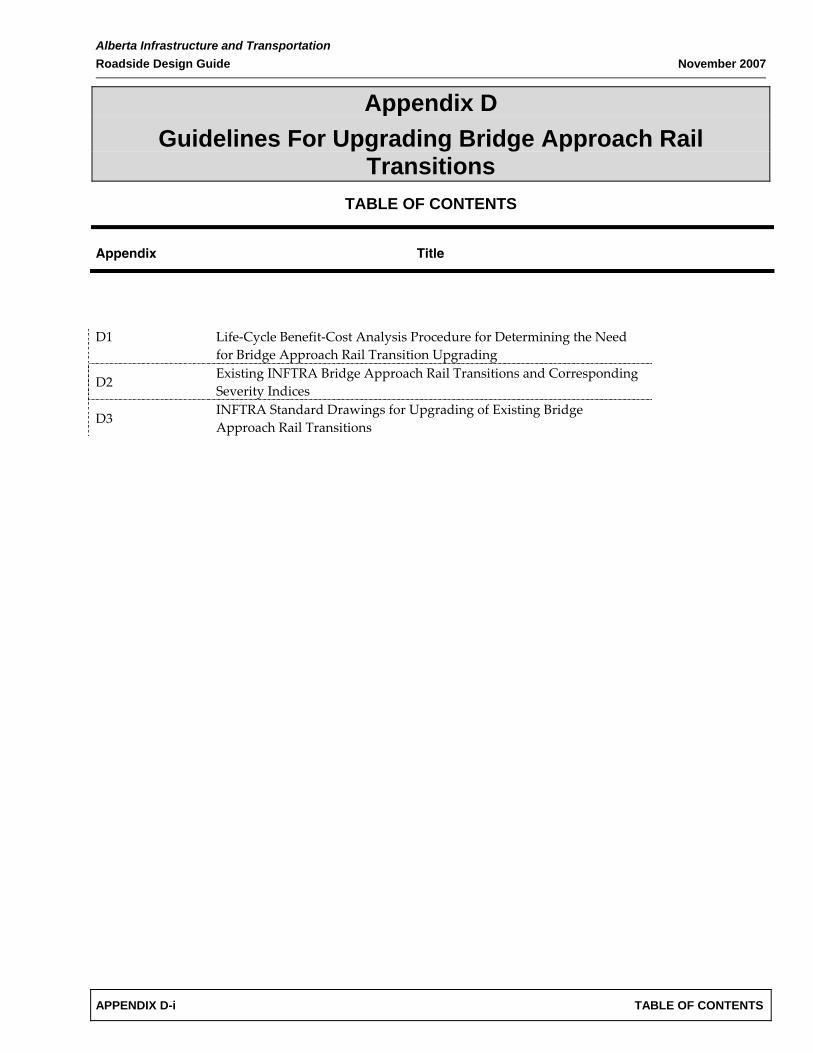
D1
Life‐Cycle Benefit‐Cost Analysis Procedure for Determining the Need for Bridge Approach Rail Transition Upgrading
D2 Existing INFTRA Bridge Approach Rail Transitions and Corresponding Severity Indices
D3 INFTRA Standard Drawings for Upgrading of Existing Bridge Approach Rail Transitions

Alberta Infrastructure and Transportation November 2007 Roadside Design Guide
TABLE OF CONTENTS APPENDIX D-ii
THIS PAGE INTENTIONALLY LEFT BLANK

Alberta Infrastructure and Transportation Roadside Design Guide November 2007
APPENDIX D1 COVER PAGE
APPENDIX D1
LIFE‐CYCLE BENEFIT‐COST ANALYSIS PROCEDURE FOR DETERMINING THE NEED FOR BRIDGE APPROACH RAIL
TRANSITION UPGRADING

Alberta Infrastructure and Transportation November 2007 Roadside Design Guide
COVER PAGE APPENDIX D1
THIS PAGE INTENTIONALLY LEFT BLANK
Alberta Infrastructure and TransportationRoadside Design Guide November 2007
Appendix D1Life-Cycle Benefit-Cost Analysis Procedure
for Determining the Need forBridge Approach Rail Transition Upgrading
TABLE OF CONTENTS
Appendix Title Page Number
APPENDIX D1-i TABLE OF CONTENTS
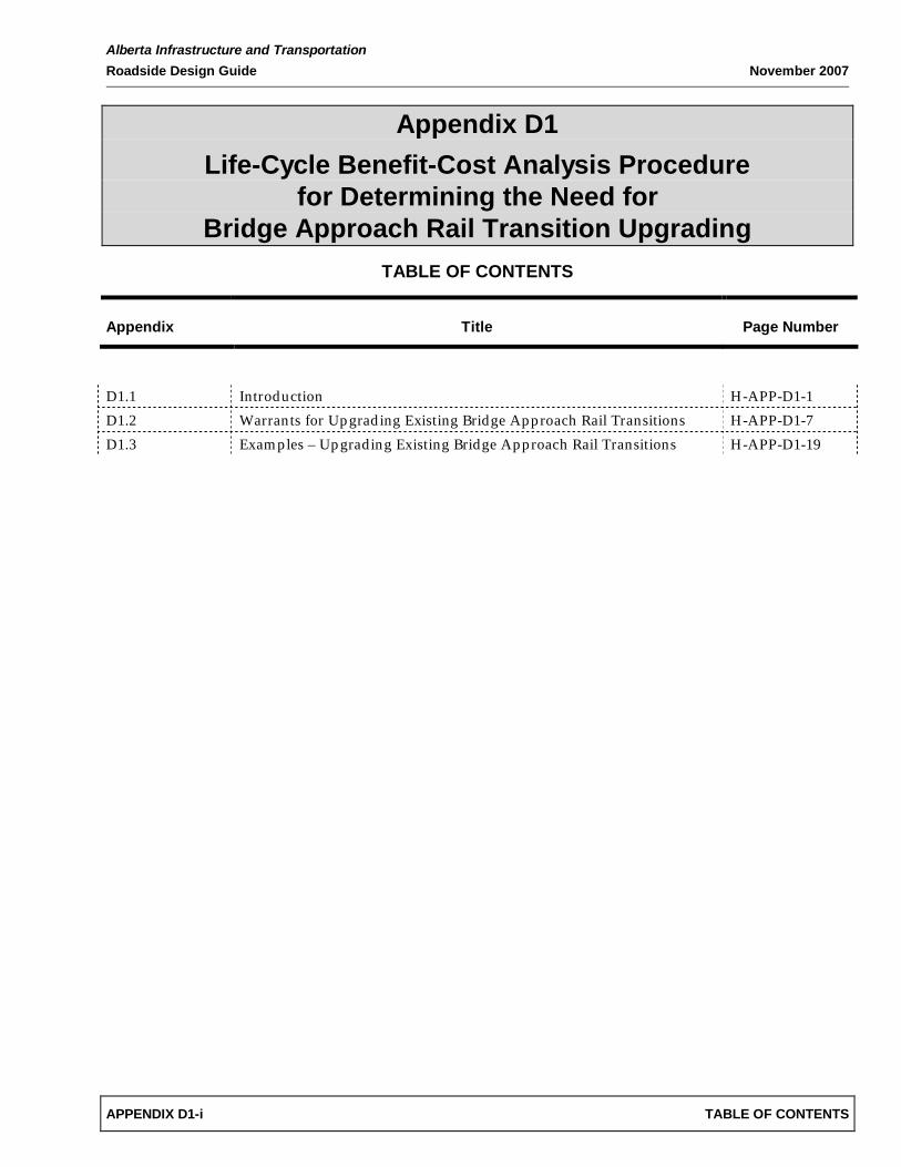
D1.1 Introduction H-APP-D1-1D1.2 Warrants for Upgrading Existing Bridge Approach Rail Transitions H-APP-D1-7D1.3 Examples – Upgrading Existing Bridge Approach Rail Transitions H-APP-D1-19

Alberta Infrastructure and Transportation November 2007 Roadside Design Guide
TABLE OF CONTENTS APPENDIX D1-ii
THIS PAGE INTENTIONALLY LEFT BLANK
Alberta Infrastructure and Transportation Roadside Design Guide November 2007
APPENDIX D1 H-APP-D1-1
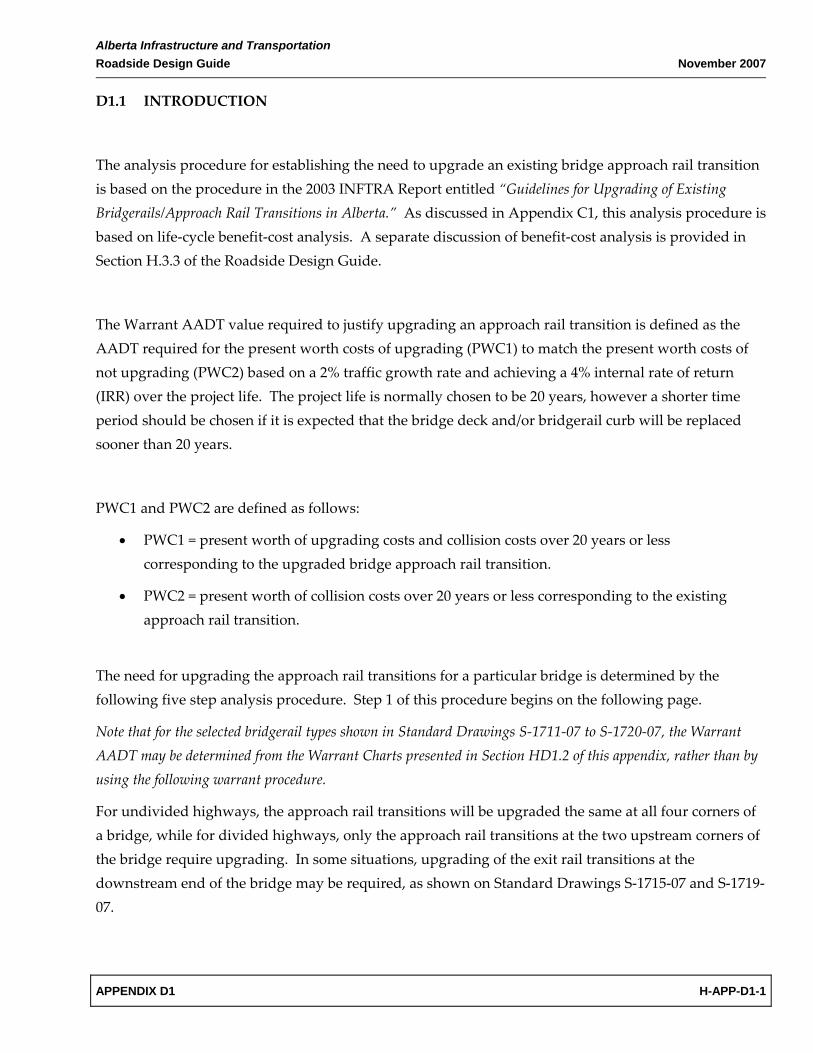
D1.1 INTRODUCTION
The analysis procedure for establishing the need to upgrade an existing bridge approach rail transition is based on the procedure in the 2003 INFTRA Report entitled “Guidelines for Upgrading of Existing Bridgerails/Approach Rail Transitions in Alberta.” As discussed in Appendix C1, this analysis procedure is based on life‐cycle benefit‐cost analysis. A separate discussion of benefit‐cost analysis is provided in Section H.3.3 of the Roadside Design Guide.
The Warrant AADT value required to justify upgrading an approach rail transition is defined as the AADT required for the present worth costs of upgrading (PWC1) to match the present worth costs of not upgrading (PWC2) based on a 2% traffic growth rate and achieving a 4% internal rate of return (IRR) over the project life. The project life is normally chosen to be 20 years, however a shorter time period should be chosen if it is expected that the bridge deck and/or bridgerail curb will be replaced sooner than 20 years.
PWC1 and PWC2 are defined as follows:
• PWC1 = present worth of upgrading costs and collision costs over 20 years or less corresponding to the upgraded bridge approach rail transition.
• PWC2 = present worth of collision costs over 20 years or less corresponding to the existing approach rail transition.
The need for upgrading the approach rail transitions for a particular bridge is determined by the following five step analysis procedure. Step 1 of this procedure begins on the following page.
Note that for the selected bridgerail types shown in Standard Drawings S‐1711‐07 to S‐1720‐07, the Warrant AADT may be determined from the Warrant Charts presented in Section HD1.2 of this appendix, rather than by using the following warrant procedure.
For undivided highways, the approach rail transitions will be upgraded the same at all four corners of a bridge, while for divided highways, only the approach rail transitions at the two upstream corners of the bridge require upgrading. In some situations, upgrading of the exit rail transitions at the downstream end of the bridge may be required, as shown on Standard Drawings S‐1715‐07 and S‐1719‐07.

Alberta Infrastructure and Transportation November 2007 Roadside Design Guide
H-APP-D1-2 APPENDIX D1
Step 1: Approach Rail Transition Upgrading Costs
Determine the total capital costs of upgrading the approach rail transitions at the corners of the bridge requiring upgrading. Divide this total cost by the number of approach rail transitions requiring upgrading to determine the average cost of upgrading one corner of the bridge. This cost must then be converted to year 2000 dollars since the collision costs used by INFTRA are based on year 2000 data (refer to Section H.3.3).
If the approach rail transitions are to be upgraded in accordance with the details shown in INFTRA Standard Drawings S‐1711‐07 to S‐1720‐07, then the cost to upgrade the approach rail transition at one corner of a bridge may be taken from Table HD1.1.
Table HD1.1 – Assumed Bridge Approach Rail Transition Upgrading Costs
Upgrading Costs (per corner of bridge)
Year 2000 dollars1 Year 2007 dollars Approach Rail Transition Upgrading Standard Drawings
Divided Highway
Undivided Highway
Divided Highway
Undivided Highway
Vertical Bar / Horizontal Rail Type Bridgerail on Safety Curb (Standard Drawings S‐1711‐07 to S‐1715‐07)
$ 10,700 $ 16,400 $ 16,100 $ 24,600
850 mm Double Tube Type Bridgerail on Safety Curb (Standard Drawings S‐1716‐07 to S‐1719‐07)
$ 8,600 $ 11,100 $ 12,900 $ 16,700
Single Layer Deep Beam (W‐Beam) Bridgerail on Participating Curb (Type 1) – Bridgerail Mounted on 127 mm dia. Std Pipe Posts – Existing Approach Rail Typically not Connected to Bridgerail (Standard Drawing S‐1720‐07) 2
$ 4,500 $ 5,500 $ 6,800 $ 8,300
Double Layer Deep Beam (W‐Beam) Bridgerail on Participating Curb (Type 2) – Bridgerail Mounted on HSS127x127x6.35 Posts – Existing Approach Rail Typically Continuous with Bridgerail (Standard Drawing S‐1720‐07) 2
$ 4,400 $ 5,300 $ 6,600 $ 8,000
Single/Double Layer Deep Beam (W‐Beam) Bridgerail on Safety Curb – Bridgerail Mounted on 127 mm dia. Std Pipe Posts – Existing Approach Rail Typically not Connected to Bridgerail (Standard Drawing S‐1720‐07) 2
$ 4,600 $ 5,600 $ 6,900 $ 8,400
Alberta Infrastructure and Transportation Roadside Design Guide November 2007
APPENDIX D1 H-APP-D1-3
1 Upgrading costs in year 2000 dollars are used in the warrant analysis procedure to be consistent with the collision costs in Table HC1.7 (Appendix C1) which are also in year 2000 dollars.
2 Includes cost of upgrading bridgerail.
Step 2: Severity Index (SI) and Corresponding Length (L)
Determine the Severity Index (SI) and corresponding length (L) of the existing approach rail transition. The corresponding length (L) is defined as the length of the approach rail transition that protects the end of the bridgerail and has the assigned severity index. The value “L” should not be confused with the physical length of the overall approach rail transition. Severity Indices and corresponding lengths are provided in Figures HD2.1 to HD2.4 (Appendix D2) for existing approach rail transitions used with different types of bridgerails.
Next, determine the Severity Index (SI) of the proposed upgraded approach rail transition. The SI value for the proposed upgraded approach rail transition must be determined based on the anticipated level of safety that the proposed upgraded transition will provide. To provide uniformity in upgrading bridge approach rail transitions across the province, standard approach rail transition upgrading drawings have been developed for the most common types of existing bridgerails currently on Alberta’s roadways. These drawings are shown in Appendix D3. A summary of SI values are summarized in Table HD1.2:

Alberta Infrastructure and Transportation November 2007 Roadside Design Guide
H-APP-D1-4 APPENDIX D1
Table HD1.2 – Standard Approach Rail Transition Upgrading Details and SI Values
SI Value of Upgraded Approach Rail Transition
Design Speed (km/h) Approach Rail Transition Upgrading Standard Drawings
60 80 100 110 120
Vertical Bar / Horizontal Rail Type Bridgerail on Safety Curb (Standard Drawings S‐1711‐07 to S‐1715‐07)
2.1 2.5 3.1 3.4 3.8
850 mm Double Tube Type Bridgerail on Safety Curb (Standard Drawings S‐1716‐07 to S‐1719‐07)
2.1 2.5 3.1 3.4 3.8
Single Layer Deep Beam (W‐Beam) Bridgerail on Participating Curb (Type 1) – Bridgerail Mounted on 127 mm dia. Std Pipe Posts – Existing Approach Rail Typically not Connected to Bridgerail (Standard Drawing S‐1720‐07)
2.1 2.6 3.3 3.6 4.0
Double Layer Deep Beam (W‐Beam) Bridgerail on Participating Curb (Type 2) – Bridgerail Mounted on HSS127x127x6.35 Posts – Existing Approach Rail Typically Continuous with Bridgerail (Standard Drawing S‐1720‐07)
2.1 2.6 3.3 3.6 4.0
Single/Double Layer Deep Beam (W‐Beam) Bridgerail on Safety Curb – Bridgerail Mounted on 127 mm dia. Std Pipe Posts – Existing Approach Rail Typically not Connected to Bridgerail (Standard Drawing S‐1720‐07)
2.1 2.6 3.3 3.6 4.0
For the few existing bridgerail types not listed in Table HD1.2, the upgrading concepts presented in the INFTRA Report entitled “Guidelines for Upgrading of Existing Bridgerails/Approach Rail Transitions in Alberta” should be reviewed for selecting an appropriate SI value for the upgraded approach rail transition.

Alberta Infrastructure and Transportation Roadside Design Guide November 2007
APPENDIX D1 H-APP-D1-5
Step 3: Determine Collision Frequency
Determine the collision frequency using the equation:
F = 1.6 * R * kc * kg * P
Where;
F = frequency of approach rail transition collisions (encroachments/km/year)
R = basic encroachment rate for assumed AADT (Appendix C1, Table HC1.1, see note below)
kc = highway curvature factor (Appendix C1, Table HC1.2)
kg = highway grade factor (Appendix C1, Table HC1.3)
P = lateral encroachment probability (Appendix C1, Table HC1.4)
Note: The basic encroachment rates shown in Table HC1.1 are multiplied by a factor of 1.6 in Step 3 to obtain the total encroachment rate for all lanes. This adjustment factor is equivalent to the Highway Multi‐Lane Factor, km, discussed in Appendix C1. Refer to the note in Appendix C1, Section HC1.1, for clarification on the encroachment data presented in Table HC1.1.
Step 4: Present Worth Collision Costs
Determine the Present Worth Collision Costs (PWCC) using the following equation:
PWCC = F * ks * AC * L * KC / 1000
Where;
F = frequency of approach rail transition collisions as defined in Step 3 (encroachments/km/year)
ks = bridge height and occupancy factor (Appendix C1, Table HC1.6)
AC = cost per collision for severity index (Appendix C1, Table HC1.7)
L = length of the existing approach rail transition that protects the end of the bridgerail and which the assigned severity index of the existing approach rail transition is representative (refer to Figure HD2.1 to HD2.4)
KC = present worth conversion factor. Annual collision costs are converted to present worth at a discount rate of 4% and a traffic growth rate of 2%. If the project life is 20 years, KC is equal to 16.252. If the project life is less than 20 years due to the condition of the existing bridge, then a different present worth conversion factor value must be used in accordance with Table HC1.8 in Appendix C1.

Alberta Infrastructure and Transportation November 2007 Roadside Design Guide
H-APP-D1-6 APPENDIX D1
Step 5: Determining “PWC1” and “PWC2”
“PWC1” is calculated by adding together the 1) present worth cost of upgrading the bridge approach rail transition (per corner of bridge) and 2) the present worth collision costs (per corner of bridge) determined in Step 4 for the upgraded approach rail transition.
“PWC2” is the present worth collision costs determined in Step 4 for the existing approach rail transition (per corner of bridge).
Conclusion: The alternative with the lowest present worth cost is the recommended alternative.
Step 6 (OPTIONAL): Iterating to Solve for the Warrant AADT
Steps 3 to 5 are repeated for different values of AADT until PWC1 equals PWC2. The AADT that yields PWC1 equal to PWC2 is the “Warrant AADT”. Upgrading of the bridge approach rail transition is warranted when the traffic volume is equal to or greater than the Warrant AADT value.

Alberta Infrastructure and Transportation Roadside Design Guide November 2007
APPENDIX D1 H-APP-D1-7
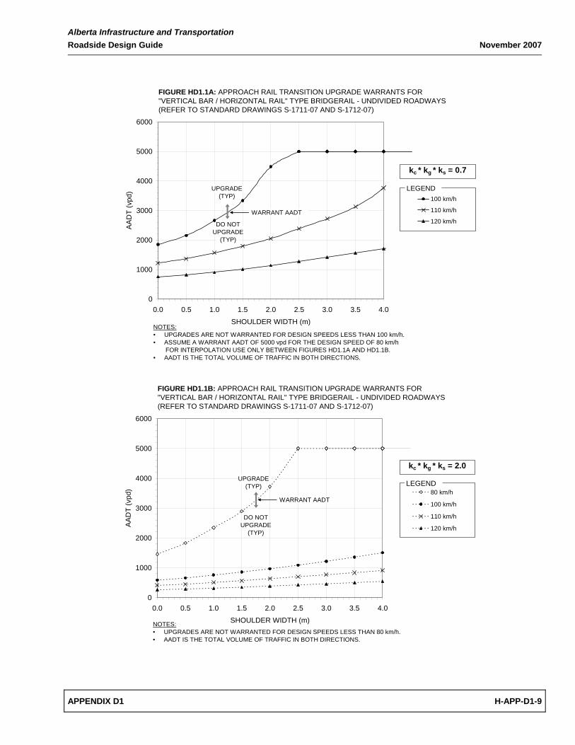
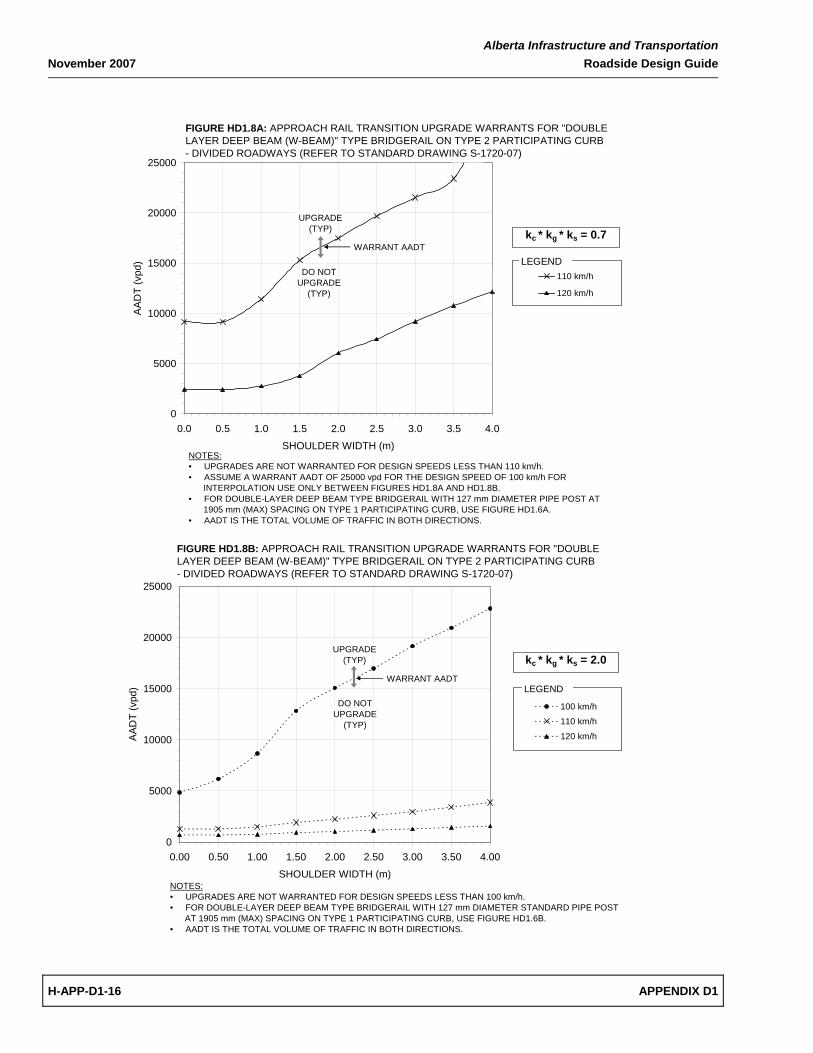
D1.2 WARRANTS FOR UPGRADING EXISTING BRIDGE APPROACH RAIL TRANSITIONS
The Warrant Charts presented in this appendix shall be used for determining the need for upgrading the approach rail transitions for the following types of existing bridgerails:
Table HD1.3 – Warrant Charts for Upgrading Bridge Approach Rail Transitions
Bridgerail Type Highway Type Standard Drawing Warrant Chart
Vertical Bar / Horizontal Rail Undivided S‐1711‐07 and S‐1712‐07
Figures HD1.1A and HD1.1B
Vertical Bar / Horizontal Rail Divided S‐1713‐07 to S‐1715‐07
Figures HD1.2A and HD1.2B
850 mm Double Tube Undivided S‐1716‐07 to S‐1718‐07
Figures HD1.3A and HD1.3B
850 mm Double Tube Divided S‐1716‐07 to S‐1719‐07
Figures HD1.4A and HD1.4B
Single Layer Deep Beam on Participating Curb (Type 1)1 Undivided S‐1720‐07 Figures HD1.5A and HD1.5B
Single Layer Deep Beam on Participating Curb (Type 1)1 Divided S‐1720‐07 Figures HD1.6A and HD1.6B
Double Layer Deep Beam on Participating Curb (Type 2)2 Undivided S‐1720‐07 Figures HD1.7A and HD1.7B
Double Layer Deep Beam on Participating Curb (Type 2)2 Divided S‐1720‐07 Figures HD1.8A and HD1.8B
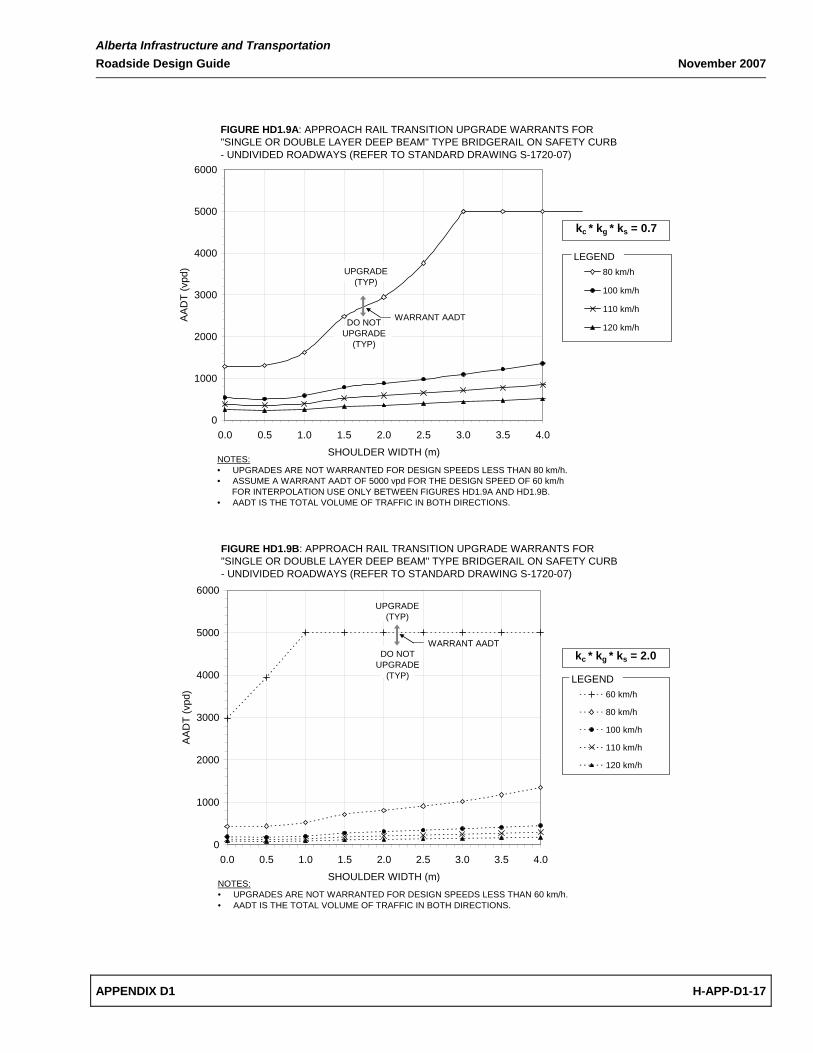
Single or Double Layer Deep Beam on Safety Curb1 Undivided S‐1720‐07 Figures HD1.9A and HD1.9B
Single or Double Layer Deep Beam on Safety Curb1 Divided S‐1720‐07 Figures HD1.10A and HD1.10B
1 Bridgerail Mounted on 127 mm dia. Std Pipe Posts – Existing Approach Rail Typically not Connected to Bridgerail.
2 Bridgerail Mounted on HSS127x127x6.35 Posts – Existing Approach Rail Typically Continuous with Bridgerail.

Alberta Infrastructure and Transportation March 2008 Roadside Design Guide
H-APP-D1-8 APPENDIX D1
These Warrant Charts have been created following the six step warranting procedure in Section HD1.1. They may be used for quickly establishing the Warrant AADT necessary to justify the upgrade of existing bridge approach rail transitions. The Warrant AADT is a function of the following variables:
• Highway Design Speed
• Highway Shoulder Width
• Highway Curvature, kc (refer to Table HC1.2 in Appendix C1)
• Highway Grade, kg (refer to Table HC1.3 in Appendix C1)
• Bridge Height and Occupancy, ks (refer to Table HC1.6 in Appendix C1) The approach rail transition warrant charts presented in Figures HD1.1A to HD1.10B are based on:
• the assumed capital costs for upgrading stated previously in Table HD1.1
• the SI values for the upgraded approach rail transitions summarized in Table HD1.2
• the SI and corresponding length values for the existing approach rail transitions shown in Figure HD2.1 to HD2.4 in Appendix D2
• a 20 year project life with a 4% discount rate and a 2% traffic growth rate.
The warrant charts are presented as two sets of curves per page to allow for linear interpolation. The set of curves in the top figure, labeled as Figure A, are based on holding the product of kc * kg * ks equal to 0.7; the set of curves in the bottom figure, labeled as Figure B, are based on holding the product of kc * kg * ks equal to 2.0. Intermediate values of kc * kg * ks can be calculated by linear interpolation between the two sets of curves. For values of kc * kg * ks exceeding 2.0, the six step detailed warrant procedure stated above should be followed.
The approach rail transition should be upgraded if the actual AADT is equal to or greater than the Warrant AADT value.
Alberta Infrastructure and Transportation Roadside Design Guide November 2007
APPENDIX D1 H-APP-D1-9
0
1000
2000
3000
4000
5000
6000
0.0 0.5 1.0 1.5 2.0 2.5 3.0 3.5 4.0
SHOULDER WIDTH (m)
AA
DT
(vpd
)
100 km/h
110 km/h
120 km/h
UPGRADE (TYP)
DO NOT UPGRADE
(TYP)
FIGURE HD1.1A: APPROACH RAIL TRANSITION UPGRADE WARRANTS FOR "VERTICAL BAR / HORIZONTAL RAIL" TYPE BRIDGERAIL - UNDIVIDED ROADWAYS(REFER TO STANDARD DRAWINGS S-1711-07 AND S-1712-07)
LEGEND
NOTES:• UPGRADES ARE NOT WARRANTED FOR DESIGN SPEEDS LESS THAN 100 km/h.• ASSUME A WARRANT AADT OF 5000 vpd FOR THE DESIGN SPEED OF 80 km/h FOR INTERPOLATION USE ONLY BETWEEN FIGURES HD1.1A AND HD1.1B.• AADT IS THE TOTAL VOLUME OF TRAFFIC IN BOTH DIRECTIONS.
WARRANT AADT
kc * kg * ks = 0.7
0
1000
2000
3000
4000
5000
6000
0.0 0.5 1.0 1.5 2.0 2.5 3.0 3.5 4.0
SHOULDER WIDTH (m)
AA
DT
(vpd
) 80 km/h
100 km/h
110 km/h
120 km/h
LEGENDUPGRADE
(TYP)
DO NOT UPGRADE
(TYP)
FIGURE HD1.1B: APPROACH RAIL TRANSITION UPGRADE WARRANTS FOR "VERTICAL BAR / HORIZONTAL RAIL" TYPE BRIDGERAIL - UNDIVIDED ROADWAYS(REFER TO STANDARD DRAWINGS S-1711-07 AND S-1712-07)
NOTES:• UPGRADES ARE NOT WARRANTED FOR DESIGN SPEEDS LESS THAN 80 km/h.• AADT IS THE TOTAL VOLUME OF TRAFFIC IN BOTH DIRECTIONS.
WARRANT AADT
kc * kg * ks = 2.0

Alberta Infrastructure and Transportation November 2007 Roadside Design Guide
H-APP-D1-10 APPENDIX D1
0
5000
10000
15000
20000
25000
0.0 0.5 1.0 1.5 2.0 2.5 3.0 3.5 4.0
SHOULDER WIDTH (m)
AA
DT
(vpd
)
100 km/h
110 km/h
120 km/h
FIGURE HD1.2A: APPROACH RAIL TRANSITION UPGRADE WARRANTS FOR "VERTICAL BAR / HORIZONTAL RAIL" TYPE BRIDGERAIL - DIVIDED ROADWAYS(REFER TO STANDARD DRAWINGS S-1713-07 TO S-1715-07)
DO NOT UPGRADE
(TYP)
LEGENDUPGRADE
(TYP)
NOTES:• UPGRADES ARE NOT WARRANTED FOR DESIGN SPEEDS LESS THAN 100 km/h.• ASSUME A WARRANT AADT OF 25000 vpd FOR THE DESIGN SPEED OF 80 km/h FOR INTERPOLATION USE ONLY BETWEEN FIGURES HD1.2A AND HD1.2B.• AADT IS THE TOTAL VOLUME OF TRAFFIC IN BOTH DIRECTIONS.
WARRANT AADT
kc * kg * ks = 0.7
0
5000
10000
15000
20000
25000
0.0 0.5 1.0 1.5 2.0 2.5 3.0 3.5 4.0
SHOULDER WIDTH (m)
AA
DT
(vpd
)
80 km/h
100 km/h
110 km/h
120 km/h
FIGURE HD1.2B: APPROACH RAIL TRANSITION UPGRADE WARRANTS FOR "VERTICAL BAR / HORIZONTAL RAIL" TYPE BRIDGERAIL - DIVIDED ROADWAYS(REFER TO STANDARD DRAWINGS S-1713-07 TO S-1715-07)
UPGRADE (TYP)
LEGEND
NOTES:• UPGRADES ARE NOT WARRANTED FOR DESIGN SPEEDS LESS THAN 80 km/h.• AADT IS THE TOTAL VOLUME OF TRAFFIC IN BOTH DIRECTIONS.
WARRANT AADT
DO NOT UPGRADE
(TYP)
kc * kg * ks = 2.0

Alberta Infrastructure and Transportation Roadside Design Guide November 2007
APPENDIX D1 H-APP-D1-11
0
1000
2000
3000
4000
5000
6000
0.0 0.5 1.0 1.5 2.0 2.5 3.0 3.5 4.0
SHOULDER WIDTH (m)
AA
DT
(vpd
)
120 km/h
UPGRADE
DO NOT UPGRADE
FIGURE HD1.3A: APPROACH RAIL TRANSITION UPGRADE WARRANTS FOR "850 mm DOUBLE TUBE" TYPE BRIDGERAIL - UNDIVIDED ROADWAYS(REFER TO STANDARD DRAWINGS S-1716-07 TO S-1718-07)
LEGEND
NOTES:• UPGRADES ARE NOT WARRANTED FOR DESIGN SPEEDS LESS THAN 120 km/h.• ASSUME A WARRANT AADT OF 5000 vpd FOR THE DESIGN SPEED OF 100 km/h AND 110 km/h FOR INTERPOLATION USE ONLY BETWEEN FIGURES HD1.3A AND HD1.3B.• AADT IS THE TOTAL VOLUME OF TRAFFIC IN BOTH DIRECTIONS.
WARRANT AADT
kc * kg * ks = 0.7
0
1000
2000
3000
4000
5000
6000
0.0 0.5 1.0 1.5 2.0 2.5 3.0 3.5 4.0
SHOULDER WIDTH (m)
AAD
T (v
pd)
100 km/h110 km/h120 km/h
LEGENDUPGRADE
(TYP)
DO NOT UPGRADE
(TYP)
FIGURE HD1.3B: APPROACH RAIL TRANSITION UPGRADE WARRANTS FOR "850 mm DOUBLE TUBE" TYPE BRIDGERAIL - UNDIVIDED ROADWAYS(REFER TO STANDARD DRAWINGS S-1716-07 TO S-1718-07)
NOTES:• UPGRADES ARE NOT WARRANTED FOR DESIGN SPEEDS LESS THAN 100 km/h.• AADT IS THE TOTAL VOLUME OF TRAFFIC IN BOTH DIRECTIONS.
WARRANT AADT
kc * kg * ks = 2.0

Alberta Infrastructure and Transportation November 2007 Roadside Design Guide
H-APP-D1-12 APPENDIX D1
0
5000
10000
15000
20000
25000
0.0 0.5 1.0 1.5 2.0 2.5 3.0 3.5 4.0
SHOULDER WIDTH (m)
AA
DT
(vpd
)
120 km/h
FIGURE HD1.4A: APPROACH RAIL TRANSITION UPGRADE WARRANTS FOR "850 mm DOUBLE TUBE" TYPE BRIDGERAIL - DIVIDED ROADWAYS(REFER TO STANDARD DRAWINGS S-1716-07 TO S-1719-07)
DO NOT UPGRADE
LEGEND
UPGRADE
NOTES:• UPGRADES ARE NOT WARRANTED FOR DESIGN SPEEDS LESS THAN 120 km/h.• ASSUME A WARRANT AADT OF 25000 vpd FOR DESIGN SPEEDS OF 100 km/h AND 110 kph FOR INTERPOLATION USE ONLY BETWEEN FIGURES HD1.4A AND HD1.4B.• AADT IS THE TOTAL VOLUME OF TRAFFIC IN BOTH DIRECTIONS.
WARRANT AADTkc * kg * ks = 0.7
0
5000
10000
15000
20000
25000
0.0 0.5 1.0 1.5 2.0 2.5 3.0 3.5 4.0
SHOULDER WIDTH (m)
AA
DT
(vpd
)
100 km/h110 km/h120 km/h
kc * kg * ks = 2.0
FIGURE HD1.4B: APPROACH RAIL TRANSITION UPGRADE WARRANTS FOR "850 mm DOUBLE TUBE" TYPE BRIDGERAIL - DIVIDED ROADWAYS(REFER TO STANDARD DRAWINGS S-1716-07 TO S-1719-07)
UPGRADE (TYP)
DO NOT UPGRADE
(TYP)
LEGEN
NOTES:• UPGRADES ARE NOT WARRANTED FOR DESIGN SPEEDS LESS THAN 100 km/h.• AADT IS THE TOTAL VOLUME OF TRAFFIC IN BOTH DIRECTIONS.
WARRANT AADT

Alberta Infrastructure and Transportation Roadside Design Guide November 2007
APPENDIX D1 H-APP-D1-13
0
1000
2000
3000
4000
5000
6000
0.0 0.5 1.0 1.5 2.0 2.5 3.0 3.5 4.0
SHOULDER WIDTH (m)
AA
DT
(vpd
)
80 km/h
100 km/h
110 km/h
120 km/h
DO NOT UPGRADE
(TYP)
FIGURE HD1.5A: APPROACH RAIL TRANSITION UPGRADE WARRANTS FOR "SINGLE LAYER DEEP BEAM (W-BEAM)" TYPE BRIDGERAIL ON TYPE 1 PARTICIPATING CURB- UNDIVIDED ROADWAYS (REFER TO STANDARD DRAWING S-1720-07)
LEGEND
NOTES:• UPGRADES ARE NOT WARRANTED FOR DESIGN SPEEDS LESS THAN 80 km/h.• AADT IS THE TOTAL VOLUME OF TRAFFIC IN BOTH DIRECTIONS.
WARRANT AADT
UPGRADE (TYP)
kc * kg * ks = 0.7
0
1000
2000
3000
4000
5000
6000
0.0 0.5 1.0 1.5 2.0 2.5 3.0 3.5 4.0
SHOULDER WIDTH (m)
AA
DT
(vpd
)
80 km/h
100 km/h
110 km/h
120 km/h
DO NOT UPGRADE
(TYP)
FIGURE HD1.5B: APPROACH RAIL TRANSITION UPGRADE WARRANTS FOR "SINGLE LAYER DEEP BEAM (W-BEAM)" TYPE BRIDGERAIL ON TYPE 1 PARTICIPATING CURB- UNDIVIDED ROADWAYS (REFER TO STANDARD DRAWING S-1720-07)
LEGEND
NOTES:• UPGRADES ARE NOT WARRANTED FOR DESIGN SPEEDS LESS THAN 80 km/h.• AADT IS THE TOTAL VOLUME OF TRAFFIC IN BOTH DIRECTIONS.
WARRANT AADT
UPGRADE (TYP)
kc * kg * ks = 2.0

Alberta Infrastructure and Transportation November 2007 Roadside Design Guide
H-APP-D1-14 APPENDIX D1
0
5000
10000
15000
20000
25000
0.0 0.5 1.0 1.5 2.0 2.5 3.0 3.5 4.0
SHOULDER WIDTH (m)
AA
DT
(vpd
) 80 km/h
100 km/h
110 km/h
120 km/h
FIGURE HD1.6A: APPROACH RAIL TRANSITION UPGRADE WARRANTS FOR "SINGLE LAYER DEEP BEAM (W-BEAM)" TYPE BRIDGERAIL ON TYPE 1 PARTICIPATING CURB- DIVIDED ROADWAYS (REFER TO STANDARD DRAWING S-1720-07)
UPGRADE (TYP)
LEGEND
NOTES:• UPGRADES ARE NOT WARRANTED FOR DESIGN SPEEDS LESS THAN 80 km/h.• AADT IS THE TOTAL VOLUME OF TRAFFIC IN BOTH DIRECTIONS.
WARRANT AADT
DO NOT UPGRADE
(TYP)
kc * kg * ks = 0.7
0
5000
10000
15000
20000
25000
0.0 0.5 1.0 1.5 2.0 2.5 3.0 3.5 4.0
SHOULDER WIDTH (m)
AA
DT
(vpd
)
80 km/h
100 km/h
110 km/h
120 km/h
FIGURE HD1.6B: APPROACH RAIL TRANSITION UPGRADE WARRANTS FOR "SINGLE LAYER DEEP BEAM (W-BEAM)" TYPE BRIDGERAIL ON TYPE 1 PARTICIPATING CURB- DIVIDED ROADWAYS (REFER TO STANDARD DRAWING S-1720-07)
DO NOT UPGRADE
(TYP)
LEGEND
NOTES:• UPGRADES ARE NOT WARRANTED FOR DESIGN SPEEDS LESS THAN 80 km/h.• AADT IS THE TOTAL VOLUME OF TRAFFIC IN BOTH DIRECTIONS.
WARRANT AADT
UPGRADE (TYP)
kc * kg * ks = 2.0
Alberta Infrastructure and Transportation Roadside Design Guide November 2007
APPENDIX D1 H-APP-D1-15
0
1000
2000
3000
4000
5000
6000
0.0 0.5 1.0 1.5 2.0 2.5 3.0 3.5 4.0
SHOULDER WIDTH (m)
AAD
T (v
pd)
110 km/h
120 km/h
NOTES:• UPGRADES ARE NOT WARRANTED FOR DESIGN SPEEDS LESS THAN 110 km/h.• ASSUME A WARRANT AADT OF 5000 vpd FOR THE DESIGN SPEED OF 100 km/h FOR INTERPOLATION USE ONLY BETWEEN FIGURES HD1.7A AND HD1.7B.• FOR DOUBLE-LAYER DEEP BEAM TYPE BRIDGERAIL WITH 127 mm DIAMETER PIPE POST AT 1905 mm (MAX) SPACING ON TYPE 1 PARTICIPATING CURB, USE FIGURE HD1.5A.• AADT IS THE TOTAL VOLUME OF TRAFFIC IN BOTH DIRECTIONS.
UPGRADE (TYP)
DO NOT UPGRADE
(TYP)
FIGURE HD1.7A: APPROACH RAIL TRANSITION UPGRADE WARRANTS FOR "DOUBLE LAYER DEEP BEAM (W-BEAM)" TYPE BRIDGERAIL ON TYPE 2 PARTICIPATING CURB- UNDIVIDED ROADWAYS (REFER TO STANDARD DRAWING S-1720-07)
LEGEND
WARRANT AADT
kc * kg * ks = 0.7
0
1000
2000
3000
4000
5000
6000
0.0 0.5 1.0 1.5 2.0 2.5 3.0 3.5 4.0
SHOULDER WIDTH (m)
AA
DT
(vpd
)
100 km/h
110 km/h
120 km/h
LEGEND
DO NOT UPGRADE
(TYP)
FIGURE HD1.7B: APPROACH RAIL TRANSITION UPGRADE WARRANTS FOR "DOUBLE LAYER DEEP BEAM (W-BEAM)" TYPE BRIDGERAIL ON TYPE 2 PARTICIPATING CURB- UNDIVIDED ROADWAYS (REFER TO STANDARD DRAWING S-1720-07)
UPGRADE (TYP)
NOTES:• UPGRADES ARE NOT WARRANTED FOR DESIGN SPEEDS LESS THAN 100 km/h.• FOR DOUBLE-LAYER DEEP BEAM TYPE BRIDGERAIL WITH 127 mm DIAMETER STANDARD PIPE POST AT 1905 mm (MAX) SPACING ON TYPE 1 PARTICIPATING CURB, USE FIGURE HD1.5B.• AADT IS THE TOTAL VOLUME OF TRAFFIC IN BOTH DIRECTIONS.
WARRANT AADT
kc * kg * ks = 2.0
Alberta Infrastructure and Transportation November 2007 Roadside Design Guide
H-APP-D1-16 APPENDIX D1
0
5000
10000
15000
20000
25000
0.0 0.5 1.0 1.5 2.0 2.5 3.0 3.5 4.0
SHOULDER WIDTH (m)
AA
DT
(vpd
)
110 km/h
120 km/h
NOTES:• UPGRADES ARE NOT WARRANTED FOR DESIGN SPEEDS LESS THAN 110 km/h.• ASSUME A WARRANT AADT OF 25000 vpd FOR THE DESIGN SPEED OF 100 km/h FOR INTERPOLATION USE ONLY BETWEEN FIGURES HD1.8A AND HD1.8B.• FOR DOUBLE-LAYER DEEP BEAM TYPE BRIDGERAIL WITH 127 mm DIAMETER PIPE POST AT 1905 mm (MAX) SPACING ON TYPE 1 PARTICIPATING CURB, USE FIGURE HD1.6A.• AADT IS THE TOTAL VOLUME OF TRAFFIC IN BOTH DIRECTIONS.
FIGURE HD1.8A: APPROACH RAIL TRANSITION UPGRADE WARRANTS FOR "DOUBLE LAYER DEEP BEAM (W-BEAM)" TYPE BRIDGERAIL ON TYPE 2 PARTICIPATING CURB- DIVIDED ROADWAYS (REFER TO STANDARD DRAWING S-1720-07)
LEGEND
UPGRADE (TYP)
DO NOT UPGRADE
(TYP)
WARRANT AADTkc * kg * ks = 0.7
0
5000
10000
15000
20000
25000
0.00 0.50 1.00 1.50 2.00 2.50 3.00 3.50 4.00
SHOULDER WIDTH (m)
AAD
T (v
pd)
100 km/h
110 km/h
120 km/h
FIGURE HD1.8B: APPROACH RAIL TRANSITION UPGRADE WARRANTS FOR "DOUBLE LAYER DEEP BEAM (W-BEAM)" TYPE BRIDGERAIL ON TYPE 2 PARTICIPATING CURB- DIVIDED ROADWAYS (REFER TO STANDARD DRAWING S-1720-07)
UPGRADE (TYP)
DO NOT UPGRADE
(TYP)
LEGEND
NOTES:• UPGRADES ARE NOT WARRANTED FOR DESIGN SPEEDS LESS THAN 100 km/h.• FOR DOUBLE-LAYER DEEP BEAM TYPE BRIDGERAIL WITH 127 mm DIAMETER STANDARD PIPE POST AT 1905 mm (MAX) SPACING ON TYPE 1 PARTICIPATING CURB, USE FIGURE HD1.6B.• AADT IS THE TOTAL VOLUME OF TRAFFIC IN BOTH DIRECTIONS.
WARRANT AADT
kc * kg * ks = 2.0
Alberta Infrastructure and Transportation Roadside Design Guide November 2007
APPENDIX D1 H-APP-D1-17
0
1000
2000
3000
4000
5000
6000
0.0 0.5 1.0 1.5 2.0 2.5 3.0 3.5 4.0
SHOULDER WIDTH (m)
AA
DT
(vpd
) 80 km/h
100 km/h
110 km/h
120 km/h
UPGRADE (TYP)
FIGURE HD1.9A: APPROACH RAIL TRANSITION UPGRADE WARRANTS FOR"SINGLE OR DOUBLE LAYER DEEP BEAM" TYPE BRIDGERAIL ON SAFETY CURB- UNDIVIDED ROADWAYS (REFER TO STANDARD DRAWING S-1720-07)
LEGEND
NOTES:• UPGRADES ARE NOT WARRANTED FOR DESIGN SPEEDS LESS THAN 80 km/h.• ASSUME A WARRANT AADT OF 5000 vpd FOR THE DESIGN SPEED OF 60 km/h FOR INTERPOLATION USE ONLY BETWEEN FIGURES HD1.9A AND HD1.9B.• AADT IS THE TOTAL VOLUME OF TRAFFIC IN BOTH DIRECTIONS.
WARRANT AADTDO NOT UPGRADE
(TYP)
kc * kg * ks = 0.7
0
1000
2000
3000
4000
5000
6000
0.0 0.5 1.0 1.5 2.0 2.5 3.0 3.5 4.0
SHOULDER WIDTH (m)
AA
DT
(vpd
) 60 km/h
80 km/h
100 km/h
110 km/h
120 km/h
LEGEND
UPGRADE (TYP)
DO NOT UPGRADE
(TYP)
FIGURE HD1.9B: APPROACH RAIL TRANSITION UPGRADE WARRANTS FOR"SINGLE OR DOUBLE LAYER DEEP BEAM" TYPE BRIDGERAIL ON SAFETY CURB- UNDIVIDED ROADWAYS (REFER TO STANDARD DRAWING S-1720-07)
NOTES:• UPGRADES ARE NOT WARRANTED FOR DESIGN SPEEDS LESS THAN 60 km/h.• AADT IS THE TOTAL VOLUME OF TRAFFIC IN BOTH DIRECTIONS.
WARRANT AADTkc * kg * ks = 2.0

Alberta Infrastructure and Transportation November 2007 Roadside Design Guide
H-APP-D1-18 APPENDIX D1
0
5000
10000
15000
20000
25000
0.0 0.5 1.0 1.5 2.0 2.5 3.0 3.5 4.0
SHOULDER WIDTH (m)
AA
DT
(vpd
) 80 km/h
100 km/h
110 km/h
120 km/h
FIGURE HD1.10A: APPROACH RAIL TRANSITION UPGRADE WARRANTS FOR"SINGLE OR DOUBLE LAYER DEEP BEAM" TYPE BRIDGERAIL ON SAFETY CURB- DIVIDED ROADWAYS (REFER TO STANDARD DRAWING S-1720-07)
UPGRADE (TYP)
DO NOT UPGRADE
(TYP)
LEGEND
NOTES:• UPGRADES ARE NOT WARRANTED FOR DESIGN SPEEDS LESS THAN 80 km/h.• ASSUME A WARRANT AADT OF 25000 vpd FOR THE DESIGN SPEED OF 60 km/h FOR INTERPOLATION USE ONLY BETWEEN FIGURES HD1.10A AND HD1.10B.• AADT IS THE TOTAL VOLUME OF TRAFFIC IN BOTH DIRECTIONS.
WARRANT AADT
kc * kg * ks = 0.7
0
5000
10000
15000
20000
25000
0.0 0.5 1.0 1.5 2.0 2.5 3.0 3.5 4.0
SHOULDER WIDTH (m)
AAD
T (v
pd) 60 km/h
80 km/h
100 km/h
110 km/h
120 km/h
FIGURE HD1.10B: APPROACH RAIL TRANSITION UPGRADE WARRANTS FOR"SINGLE OR DOUBLE LAYER DEEP BEAM" TYPE BRIDGERAIL ON SAFETY CURB- DIVIDED ROADWAYS (REFER TO STANDARD DRAWING S-1720-07)
UPGRADE (TYP)
DO NOT UPGRADE
(TYP)
LEGEND
NOTES:• UPGRADES ARE NOT WARRANTED FOR DESIGN SPEEDS LESS THAN 60 km/h.• AADT IS THE TOTAL VOLUME OF TRAFFIC IN BOTH DIRECTIONS.
WARRANT AADTkc * kg * ks = 2.0
Alberta Infrastructure and Transportation Roadside Design Guide November 2007
APPENDIX D1 H-APP-D1-19
D1.3 EXAMPLES ‐ UPGRADING EXISTING BRIDGE APPROACH RAIL TRANSITIONS
The three bridgerail upgrading examples from Appendix C1 are continued below to demonstrate the steps required to determine the Warrant AADT for upgrading the approach rail transitions. In the first example, the product of factors kc * kg * ks is greater than 2.0 which is outside the realm of the approach rail transition upgrading warrant charts. Therefore, the decision of whether or not to upgrade the approach rail transition is based on following the six step detailed warrant procedure. In the second example, the product of factors kc * kg * ks is equal to 0.70, allowing the warrant charts to be used directly. In the third example, the product of kc * kg * ks is between 0.7 and 2.0, and therefore the Warrant AADT is determined using linear interpolation between the warrant chart curves. EXAMPLE 1 – BRIDGE #1 (kc * kg * ks greater than 2.0) Bridge and Highway Data:
• Refer to Example 1 in Appendix C1 • Refer to Standard Drawings S‐1711‐07 to S‐1715‐07 for approach rail upgrading details.
Calculations:
• kc = 1.9 from Table HC1.2 (Appendix C1) • kg = 1.0 from Table HC1.3 (Appendix C1) • ks = 1.3 from Table HC1.6 (Appendix C1) • Since the product kc * kg * ks is greater than 2.0, the need for approach rail transition upgrading
must be determined using the detailed six step procedure. o Step 1 – Upgrading Costs
Cost to upgrade the approach rail transition is $16,400 per corner of bridge, in year 2000 dollars (Table HD1.1)
o Step 2 – Severity Index (SI) and Corresponding Length (L) SI of the upgraded approach rail transition is 3.1 (Table HD1.2) SI of the existing approach rail transition is 5.6 with a corresponding length of 8.5
m (Figure HD2.1, Appendix D2)

Alberta Infrastructure and Transportation November 2007 Roadside Design Guide
H-APP-D1-20 APPENDIX D1
o Step 3 – Collision Frequency R = 0.53 based on linear interpolation with AADT = 1700 (Table HC1.1, Appendix
C1) P = 0.7965 based on linear interpolation with a shoulder width of 0.90 m at a
design speed of 100 km/h (Table HC1.4, Appendix C1) F = R * kc * kg * P = 0.80 encroachments/km/year
o Step 4 – Present Worth Collision Costs (PWCC = F * ks * AC * L * KC / 1000) AC1 (upgrade) = $78,000 based on linear interpolation (Table HC1.7, Appendix
C1) AC2 (no upgrade) = $265,000 (Table HC1.7, Appendix C1) L = 8.5 m (Step 2) KC = 16.252 PWCC1 (upgrade) = $11,200 collision costs per corner of bridge over 20 years PWCC2 (no upgrade) = $38,100 collision costs per corner of bridge over 20 years
o Step 5 – Determining PWC1 and PWC2 PWC1 = $16,400 (approach rail transition upgrade cost per corner of bridge) plus
$11,200 (collision costs of the upgraded approach rail transition per corner of bridge over 20 years) = $27,600
PWC2 = $38,100 (collision costs of the existing approach rail transition per corner of bridge over 20 years)
Conclusion: Since PWC1 (upgrade) < PWC2 (no upgrade), upgrading the approach rail transition at each corner of the bridge is warranted.
Alberta Infrastructure and Transportation Roadside Design Guide November 2007
APPENDIX D1 H-APP-D1-21
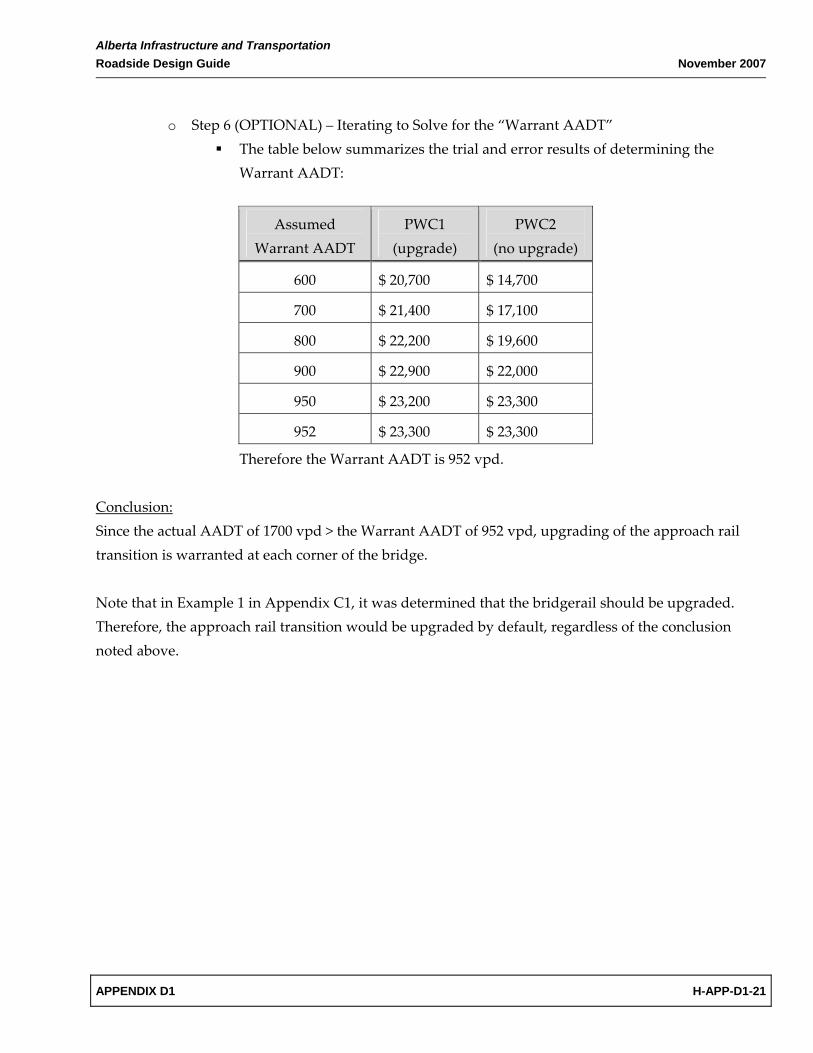
o Step 6 (OPTIONAL) – Iterating to Solve for the “Warrant AADT”
The table below summarizes the trial and error results of determining the Warrant AADT:
Assumed Warrant AADT
PWC1 (upgrade)
PWC2 (no upgrade)
600 $ 20,700 $ 14,700
700 $ 21,400 $ 17,100
800 $ 22,200 $ 19,600
900 $ 22,900 $ 22,000
950 $ 23,200 $ 23,300
952 $ 23,300 $ 23,300
Therefore the Warrant AADT is 952 vpd. Conclusion: Since the actual AADT of 1700 vpd > the Warrant AADT of 952 vpd, upgrading of the approach rail transition is warranted at each corner of the bridge. Note that in Example 1 in Appendix C1, it was determined that the bridgerail should be upgraded. Therefore, the approach rail transition would be upgraded by default, regardless of the conclusion noted above.

Alberta Infrastructure and Transportation November 2007 Roadside Design Guide
H-APP-D1-22 APPENDIX D1
EXAMPLE 2 – BRIDGE #2 (kc * kg * ks equal to 0.70) Bridge and Highway Data:
• Refer to Example 2 in Appendix C1 • Refer to Standard Drawings S‐1720‐07 for approach rail upgrading details.
Calculations:
• kc = 1.0 from Table HC1.2 (Appendix C1) • kg = 1.0 from Table HC1.3 (Appendix C1) • ks = 0.70 Table HC1.6 (Appendix C1) • Since the product kc * kg * ks is equal to 0.70, the Warrant Chart in Figure HD1.9A may be used
directly. • From Figure HD1.9A, the “Warrant AADT” corresponding to a shoulder width of 1.8 m and a
design speed of 100 km/h is approximately 920 vpd. Conclusion: Since the actual AADT of 2500 vpd > the Warrant AADT of 920 vpd, upgrading of the approach rail transition is warranted at each corner of the bridge. Note that in Example 2 in Appendix C1, it was determined that the bridgerail should not be upgraded. However, upgrading of the approach rail transition is still required.

Alberta Infrastructure and Transportation Roadside Design Guide November 2007
APPENDIX D1 H-APP-D1-23
EXAMPLE 3 – BRIDGE #3 (kc * kg * ks between 0.70 and 2.0) Bridge and Highway Data:
• Refer to Example 3 in Appendix C1 • Refer to Standard Drawings S‐1716‐07 to S‐1719‐07 for approach rail upgrading details.
Calculations:
• kc = 1.0 from Table HC1.2 (Appendix C1) • kg = 1.0 from Table HC1.3 (Appendix C1) • ks = 0.88 from Table HC1.6 (Appendix C1) • Since the product kc * kg * ks is between 0.70 and 2.0, the Warrant AADT may be determined by
linearly interpolating between the warrant charts in Figures HD1.4A and HD1.4B. o From Figure HD1.4A, the Warrant AADT corresponding to a shoulder width of 2.5 m
and a design speed of 110 km/h is 25,000 vpd for kc * kg * ks = 0.7. o From Figure HD1.4B, the Warrant AADT corresponding to a shoulder width of 2.5 m
and a design speed of 110 km/h is 13,800 vpd for kc * kg * ks = 2.0. o Using linear interpolation, the Warrant AADT is calculated as follows:
Warrant AADT = 25,000 vpd + (0.88 – 0.70) * [(13,800 vpd – 25,000 vpd) / (2.0 – 0.70)]
= 23,450 vpd Conclusion: Since the actual AADT of 9,900 vpd < the Warrant AADT of 23,450 vpd, upgrading of the approach rail transition is NOT warranted.

Alberta Infrastructure and Transportation November 2007 Roadside Design Guide
H-APP-D1-24 APPENDIX D1
THIS PAGE INTENTIONALLY LEFT BLANK

Alberta Infrastructure and Transportation Roadside Design Guide November 2007
APPENDIX D2 COVER PAGE
APPENDIX D2
EXISTING INFTRA BRIDGE APPROACH RAIL TRANSITIONS AND CORRESPONDING SEVERITY INDICES
Alberta Infrastructure and Transportation November 2007 Roadside Design Guide
COVER PAGE APPENDIX D2
THIS PAGE LEFT INTENTIONALLY BLANK

Alberta Infrastructure and Transportation Roadside Design Guide November 2007
Appendix D2 Existing INFTRA Bridge Approach Rail Transitions
and Corresponding Severity Indices
TABLE OF CONTENTS
Figure Number
Figure Title
Page Number
APPENDIX D2-i TABLE OF CONTENTS
Figure HD2.1 a.) Horizontal Rail Bridgerail on Safety Curb Approach Rail Transition b.) Vertical Bar Bridgerail on Safety Curb Approach Rail Transition H-APP-D2-1‐
Figure HD2.2
c.) Single Layer/Double Layer Deep‐Beam Bridgerail on Safety Curb Approach Rail Transition
d.) Single Layer Deep‐Beam Bridgerail on Participating Curb Approach Rail Transition
H-APP-D2‐2
Figure HD2.3 e.) Double Layer Deep‐Beam Bridgerail on Participating Curb Approach
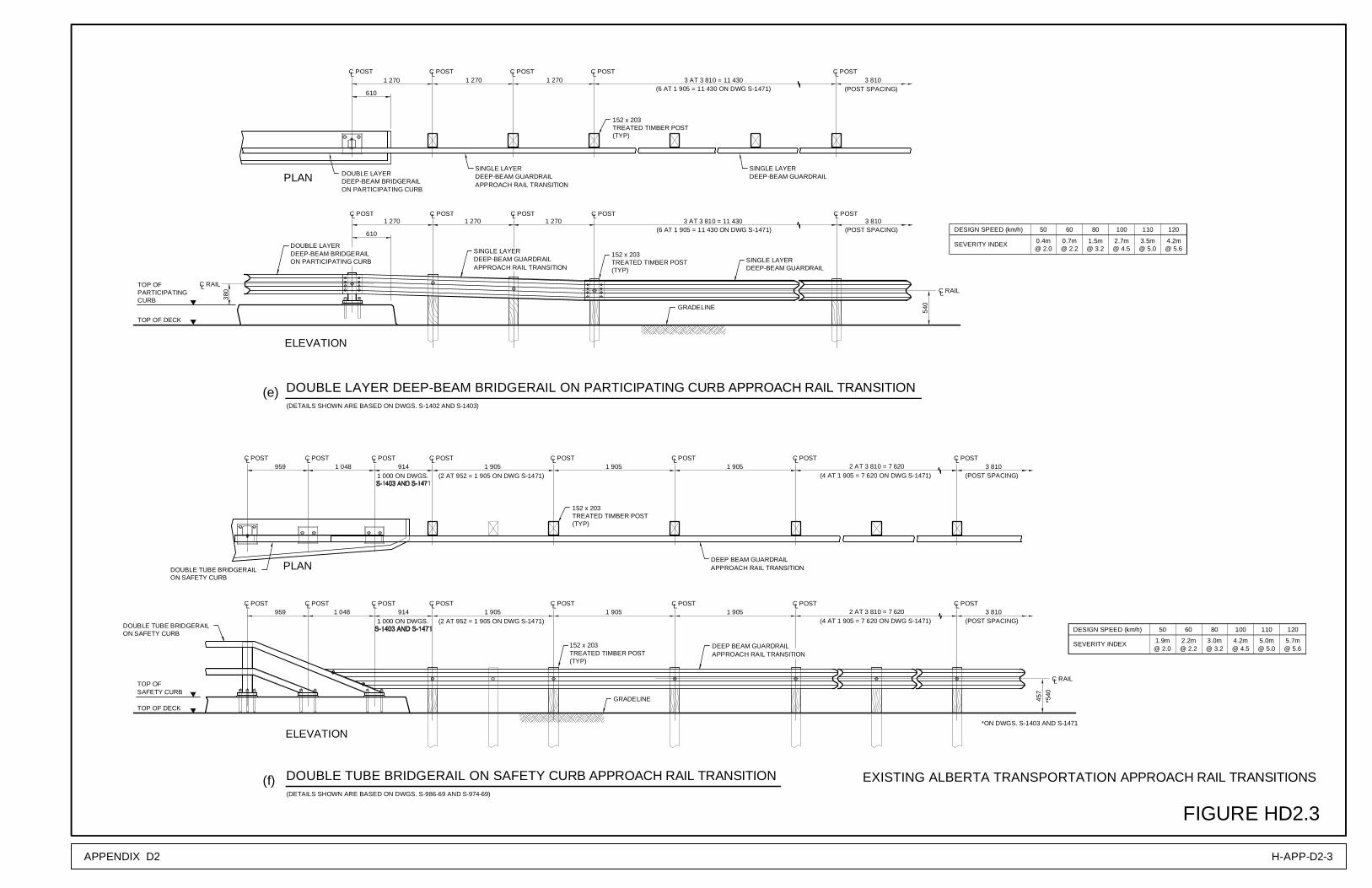
Rail Transition f.) Double Tube Bridgerail on Safety Curb Approach Rail Transition
H-APP-D2‐3
Figure HD2.4 g.) Double Tube Bridgerail on Participating Approach Rail Transition h.) Single Tube Bridgerail on Participating Curb Approach Rail
Transition H-APP-D2‐4

Alberta Infrastructure and Transportation November 2007 Roadside Design Guide
TABLE OF CONTENTS APPENDIX D2 -ii
THIS PAGE INTENTIONALLY LEFT BLANK

APPENDIX D2 H-APP-D2-1
EXISTING ALBERTA TRANSPORTATION APPROACH RAIL TRANSITIONS
FIGURE HD2.1
LC RAIL
(TYP)
152 x 203TREATED TIMBER POST
DEEP BEAM GUARDRAIL
GRADELINE
CONCRETE
C POSTL
VERTICAL BAR BRIDGERAIL ON SAFETY CURB APPROACH RAIL TRANSITION
LC POST LC POST
C POSTLC POSTL C POSTL
TREATED TIMBER POST152 x 203
(TYP)
914 1 905 1 905
PARAPET
3 810(POST SPACING)
1 905 1 905914
1 905LC POST
(POST SPACING)
L3 810
C POST1 905
PLAN
ELEVATION
L
457
C RAIL
LC POST1 905
LC POST1 905
LC POST1 905
LC POST914
152 x 203
LC POST
GRADELINE
1 905LC POST
DEEP-BEAM GUARDRAIL
1 905LC POST
PLAN
1 905
(TYP)
LC POST914
ELEVATION
(TYP)
152 x 203TREATED TIMBER POST
TREATED TIMBER POST
3 810(POST SPACING)
(POST SPACING)3 810
PARAPET
CONCRETE
HORIZONTAL RAIL BRIDGERAIL ON SAFETY CURB APPROACH RAIL TRANSITION
CONCRETE
TOP OFSAFETY CURB
TOP OF DECK
TOP OF DECK
TOP OFSAFETY CURB
ON SAFETY CURBHORIZONTAL RAIL BRIDGERAIL
RAIL DISCONTINUOUS ATCONCRETE PARAPET( DWG S-687 ONLY )
APPROACH RAILTRANSITION RETROFIT
NOTE: FOR UPSTREAM TRAFFIC, APPROACHRAIL TRANSITION LINES UP WITH FACEOF CURB (SHOWN). FOR DOWNSTREAMTRAFFIC, APPROACH RAIL TRANSITIONLINES UP WITH FACE OF BRIDGERAIL.
LINES UP WITH FACE OF BRIDGERAIL.TRAFFIC, APPROACH RAIL TRANSITIONOF CURB (SHOWN). FOR DOWNSTREAMRAIL TRANSITION LINES UP WITH FACEFOR UPSTREAM TRAFFIC, APPROACHNOTE:
(DETAILS SHOWN ARE BASED ON DWGS. S-687 AND S-974-69)
ON SAFETY CURBBRIDGERAILHORIZONTAL RAIL
PARAPET
TRANSITION RETROFITAPPROACH RAILDEEP-BEAM GUARDRAIL
PARAPETCONCRETE
APPROACH RAILTRANSITION RETROFIT
TRANSITION RETROFITAPPROACH RAILDEEP BEAM GUARDRAIL
VERTICAL BARBRIDGERAILON SAFETY CURB
BRIDGERAILON SAFETY CURB
VERTICAL BAR
(DETAILS SHOWN ARE BASED ON DWGS. S-732 AND S-974-69)
457
SEVERITY INDEX
DESIGN SPEED (km/h) 50 60
5.4m 5.8m
80
6.8m
100 110
8.5m 9.9m
120
11.4m@ 2.2 @ 2.6 @ 6.6@ 6.0@ 5.6@ 4.6
SEVERITY INDEX
DESIGN SPEED (km/h)
@ 6.611.4m
@ 2.65.8m
@ 2.25.4m
@ 5.68.5m
@ 4.66.8m
@ 6.09.9m
6050 10080 120110
(a)
(b)

EXISTING ALBERTA TRANSPORTATION APPROACH RAIL TRANSITIONS
FIGURE HD2.2
APPENDIX D2H-APP-D2-2
SINGLE LAYER / DOUBLE LAYER DEEP-BEAM BRIDGERAIL ON SAFETY CURB APPROACH RAIL TRANSITION
ELEVATION
PLAN
C POSTL C POSTL C POSTL C POSTL1 905
DEEP-BEAM GUARDRAIL
TREATED TIMBER POST152 x 203
(TYP)
1 905(POST SPACING)
3 810
DEEP-BEAM BRIDGERAILSINGLE LAYER / DOUBLE LAYER
1 905
C POSTLC POSTL C POSTL C POSTL
457
C RAILL
GRADELINE
TREATED TIMBER POST152 x 203
(TYP)
TOP OF DECK
1 905 1 905 1 905 3 810(POST SPACING)
CURBTOP OF
C POST
C POST
SINGLE LAYER DEEP-BEAM BRIDGERAIL ON PARTICIPATING CURB APPROACH RAIL TRANSITION
(TYP)
152 x 203TREATED TIMBER POST
ELEVATION
PARTICIPATINGTOP OF
CURB
TOP OF DECK
LC POST C POST1 905
PLAN
L1 905
GRADELINE
DEEP BEAM GUARDRAIL
LC POST1 905
L
LC POST
TREATED TIMBER POST
C POST1 905
152 x 203
(TYP)
L1 905
LC POST1 905
L
457
LC RAIL
(POST SPACING)3 810
(POST SPACING)3 810
FOR UPSTREAM TRAFFIC, APPROACHRAIL TRANSITION LINES UP WITH FACEOF CURB (SHOWN). FOR DOWNSTREAMTRAFFIC, APPROACH RAIL TRANSITIONLINES UP WITH FACE OF BRIDGERAIL.
NOTE:
OF CURB (SHOWN). FOR DOWNSTREAM
LINES UP WITH FACE OF BRIDGERAIL.TRAFFIC, APPROACH RAIL TRANSITION
RAIL TRANSITION LINES UP WITH FACEFOR UPSTREAM TRAFFIC, APPROACHNOTE:
914
914
ON SAFETY CURB APPROACH RAILTRANSITION RETROFIT
DEEP-BEAM BRIDGERAILSINGLE LAYER / DOUBLE LAYER
ON SAFETY CURB
DEEP-BEAM GUARDRAIL
TRANSITION RETROFITAPPROACH RAIL
(DETAILS SHOWN ARE BASED ON DWGS. S-659-69, S675-69 AND S-974-69)
TRANSITION RETROFITAPPROACH RAIL
APPROACH RAILTRANSITION RETROFIT
DEEP BEAM GUARDRAIL
914
914
DEEP-BEAM BRIDGERAILSINGLE LAYER
ON PARTICIPATING CURB
(DETAILS SHOWN ARE BASED ON DWGS. S-659-69, S-675-69 AND S-974-69)
SINGLE LAYER
ON PARTICIPATING CURBDEEP-BEAM BRIDGERAIL
SEVERITY INDEX
DESIGN SPEED (km/h)
@ 6.611.4m
@ 2.65.8m
@ 2.25.4m
@ 5.68.5m
@ 4.66.8m
@ 6.09.9m
6050 10080 120110
DESIGN SPEED (km/h)
SEVERITY INDEX 8.4m@ 6.6
6.9m3.8m 5.5m2.4m 2.8m@ 2.6@ 2.2 @ 5.6@ 4.6 @ 6.0
6050 80 100 110 120
(c)
(d)
APPENDIX D2 H-APP-D2-3
EXISTING ALBERTA TRANSPORTATION APPROACH RAIL TRANSITIONS
FIGURE HD2.3
DOUBLE TUBE BRIDGERAIL ON SAFETY CURB APPROACH RAIL TRANSITION
ELEVATION
SAFETY CURBTOP OF
C POST
C POST
DOUBLE LAYER DEEP-BEAM BRIDGERAIL ON PARTICIPATING CURB APPROACH RAIL TRANSITION
DOUBLE LAYER
ELEVATION
LC POST
DEEP-BEAM BRIDGERAIL
TREATED TIMBER POST
1 905L
(TYP)
152 x 203
C POST L1 905
L
DEEP BEAM GUARDRAIL
C POST
PLAN
GRADELINE
LC POST
TREATED TIMBER POST
C POST1 270
152 x 203
(TYP)
L L
540
LC RAIL
(POST SPACING)3 810
(POST SPACING)3 8101 270
C POSTL3 AT 3 810 = 11 430
C POSTL
610
1 270
C POSTLC POSTLC POSTLC POSTLC POSTL
152 x 203TREATED TIMBER POST(TYP)
TOP OF DECK
1 2701 2701 270
SINGLE LAYERDEEP-BEAM GUARDRAIL
TOP OFPARTICIPATINGCURB
LC POSTLC POSTLC POST1 9059141 048959
DOUBLE TUBE BRIDGERAILON SAFETY CURB
152 x 203TREATED TIMBER POST(TYP)
DEEP BEAM GUARDRAIL
GRADELINE
C POSTL959
C POSTL C POST1 048
L914
LC POST1 905
LC POST1 905
LC POST
(POST SPACING)1 905 3 810
LC POST
TOP OF DECK
PLAN
ON PARTICIPATING CURB
(6 AT 1 905 = 11 430 ON DWG S-1471)
APPROACH RAIL TRANSITION
APPROACH RAIL TRANSITIONDEEP-BEAM GUARDRAILSINGLE LAYER
(6 AT 1 905 = 11 430 ON DWG S-1471)3 AT 3 810 = 11 430
610
DOUBLE LAYERDEEP-BEAM BRIDGERAILON PARTICIPATING CURB
380
C RAILL
(DETAILS SHOWN ARE BASED ON DWGS. S-1402 AND S-1403)
(DETAILS SHOWN ARE BASED ON DWGS. S-986-69 AND S-974-69)
1 000 ON DWGS. (2 AT 952 = 1 905 ON DWG S-1471)
LC POST
(POST SPACING)3 810
C POSTL
C RAILL
457
*540
*ON DWGS. S-1403 AND S-1471
APPROACH RAIL TRANSITION
APPROACH RAIL TRANSITION
DOUBLE TUBE BRIDGERAILON SAFETY CURB
1 000 ON DWGS. (2 AT 952 = 1 905 ON DWG S-1471)
SINGLE LAYERDEEP-BEAM GUARDRAIL
SINGLE LAYERDEEP-BEAM GUARDRAIL
2 AT 3 810 = 7 620(4 AT 1 905 = 7 620 ON DWG S-1471)
2 AT 3 810 = 7 620(4 AT 1 905 = 7 620 ON DWG S-1471)
SEVERITY INDEX 0.4m 0.7m 1.5m 2.7m 3.5m@ 2.0 @ 3.2@ 2.2 @ 4.5 @ 5.0
DESIGN SPEED (km/h) 50 60 80 100 110
4.2m@ 5.6
120
1101008050 60DESIGN SPEED (km/h)
@ 2.0SEVERITY INDEX 1.9m 3.0m2.2m
@ 3.2@ 2.25.0m4.2m@ 5.0@ 4.5
120
5.7m@ 5.6
(f)
(e)

EXISTING ALBERTA TRANSPORTATION APPROACH RAIL TRANSITIONS
FIGURE HD2.4
APPENDIX D2H-APP-D2-4
DEEP BEAM GUARDRAIL
DEEP-BEAM GUARDRAIL
DOUBLE TUBE BRIDGERAIL
TREATED TIMBER POST(TYP)
152 x 203
LC POST C POSTL LC POST C POSTL1 905 2 AT 3 810 = 7 6201 9051 9052 330610
C POSTC POSTLL
GRADELINE
TREATED TIMBER POST(TYP)
152 x 203
LLC POSTC POST610 2 330
LLC POSTC POST1 905
C POSTL C POSTL C POSTL1 905 1 905
TOP OF DECK
CURBPARTICIPATINGTOP OF
ELEVATION
PLAN
DOUBLE TUBE BRIDGERAIL ON PARTICIPATING CURB APPROACH RAIL TRANSITION
LC POST LC POST C POSTL C POSTL C POSTL C POSTL1 9051 905
(POST SPACING)3 8104 AT 1 905 = 7 620
C ANCHOR BOLTLC POSTL ASSEMBLY
9529521 0901 080
TREATED TIMBER POST152 x 203
(TYP)
PLAN
LC POST LC POST C POSTL LC POST C POSTL C POSTL
GRADELINE
(TYP)TREATED TIMBER POST152 x 203
CURB
TOP OFPARTICIPATING
TOP OF DECK
SINGLE TUBE BRIDGERAIL ON PARTICIPATING CURB APPROACH RAIL TRANSITION
ELEVATION
(POST SPACING)4 AT 1 905 =7 6201 9051 9059529521 0901 080LC POST
C ANCHOR BOLTASSEMBLY
L
ON PARTICIPATING CURB
ON PARTICIPATING CURBDOUBLE TUBE BRIDGERAIL
APPROACH RAIL TRANSITION
APPROACH RAIL TRANSITIONDEEP-BEAM GUARDRAIL
1 270 ONDWG S-1472
C POSTL
(POST SPACING)3 810
1 270 ONDWG S-1472
C POSTL
(POST SPACING)3 810
(DETAILS SHOWN ARE BASED ON DWGS. S-1402 AND S-1403)
SINGLE TUBE BRIDGERAILON PARTICIPATING CURB
APPROACH RAIL TRANSITION
APPROACH RAIL TRANSITIONDEEP BEAM GUARDRAIL
3 810
540
LC RAIL
ON PARTICIPATING CURBSINGLE TUBE BRIDGERAIL
(DETAILS SHOWN ARE BASED ON DWGS. S-1618-95 AND S-1471)
C RAILL
540
(4 AT 1 905 = 7 620 ON DWG S-1471)
(4 AT 1 905 = 7 620 ON DWG S-1471)2 AT 3 810 = 7 620
SEVERITY INDEX
DESIGN SPEED (km/h) 1206050 80 100 110
@ 2.2@ 2.00.7m0.4m
@ 4.5@ 3.22.7m1.5m
@ 5.6@ 5.04.2m3.5m
@ 3.21.5m
80
0.7m0.4mSEVERITY INDEX@ 2.0 @ 2.2
DESIGN SPEED (km/h) 50 60
4.2m3.5m2.7m@ 5.0@ 4.5 @ 5.6
110100 120
(g)
(h)
Alberta Infrastructure and Transportation Roadside Design Guide November 2007
APPENDIX D3 COVER PAGE
APPENDIX D3
INFTRA STANDARD DRAWINGS
FOR UPGRADING OF EXISTING BRIDGE
APPROACH RAIL TRANSITIONS

Alberta Infrastructure and Transportation November 2007 Roadside Design Guide
COVER PAGE APPENDIX D3
THIS PAGE LEFT INTENTIONALLY BLANK

Alberta Infrastructure and Transportation Roadside Design Guide November 2007
Appendix D3 INFTRA Standard Drawings for Upgrading of
Existing Bridge Approach Rail Transitions
TABLE OF CONTENTS
Dwg. No.
Drawing Title
Page Number
APPENDIX D3-i TABLE OF CONTENTS
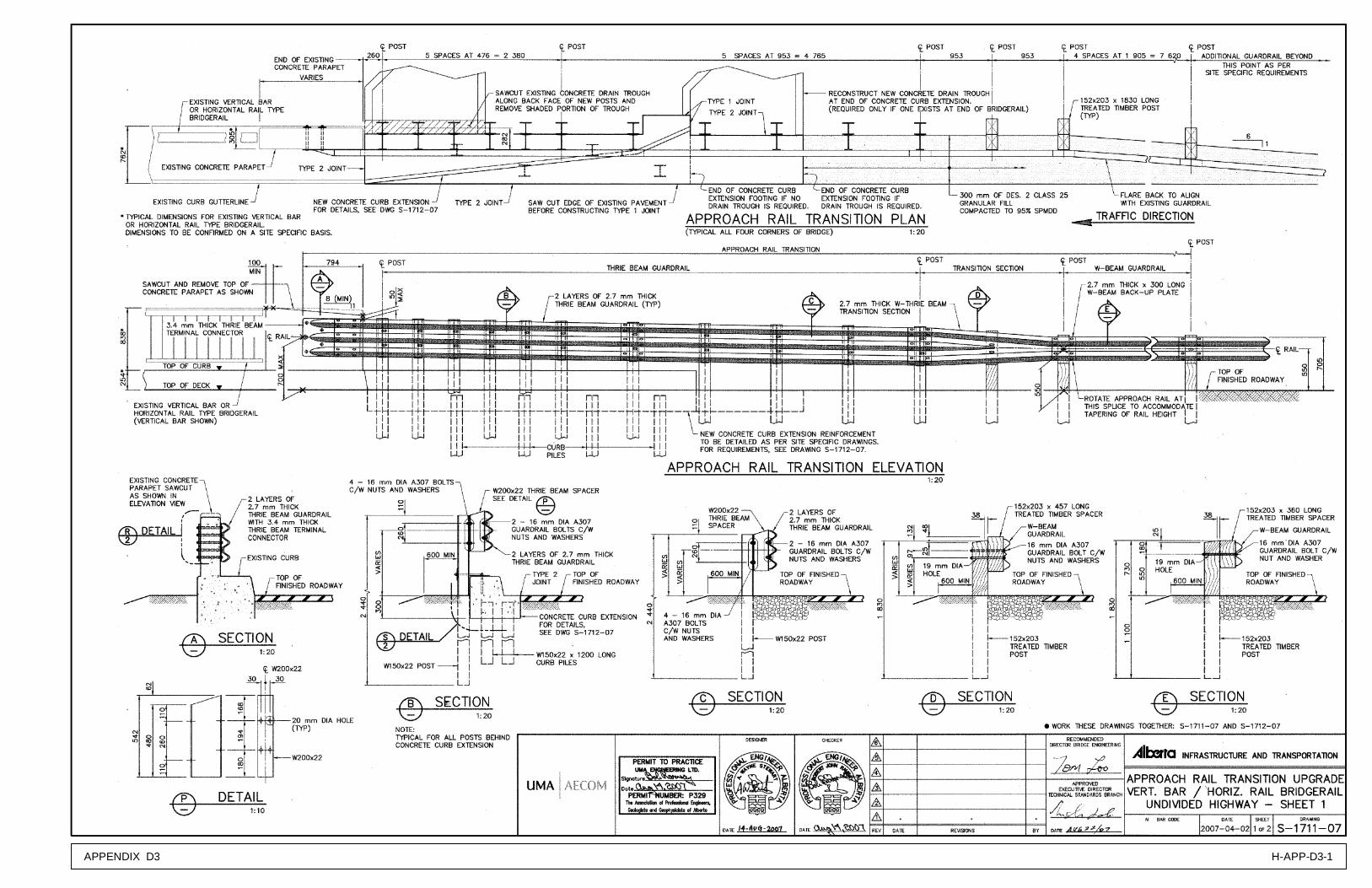
S‐1711‐07 Approach Rail Transition Upgrade Vertical Bar / Horizontal Rail Bridgerail Undivided Highway – Sheet 1 H‐APP‐D3‐1
S‐1712‐07 Approach Rail Transition Upgrade Vertical Bar / Horizontal Rail Bridgerail Undivided Highway – Sheet 2 H‐APP‐D3‐2
S‐1713‐07 Approach Rail Transition Upgrade Vertical Bar / Horizontal Rail Bridgerail Divided Highway – Sheet 1 H‐APP‐D3‐3
S‐1714‐07 Approach Rail Transition Upgrade Vertical Bar / Horizontal Rail Bridgerail Divided Highway – Sheet 2 H‐APP‐D3‐4
S‐1715‐07 Approach Rail Transition Upgrade Vertical Bar / Horizontal Rail Bridgerail Divided Highway – Sheet 3 H‐APP‐D3‐5
S‐1716‐07 Approach Rail Transition Upgrade 850 mm Double Tube Bridgerail Sheet 1 H‐APP‐D3‐6
S‐1717‐07 Approach Rail Transition Upgrade 850 mm Double Tube Bridgerail ‐ Sheet 2 H‐APP‐D3‐7
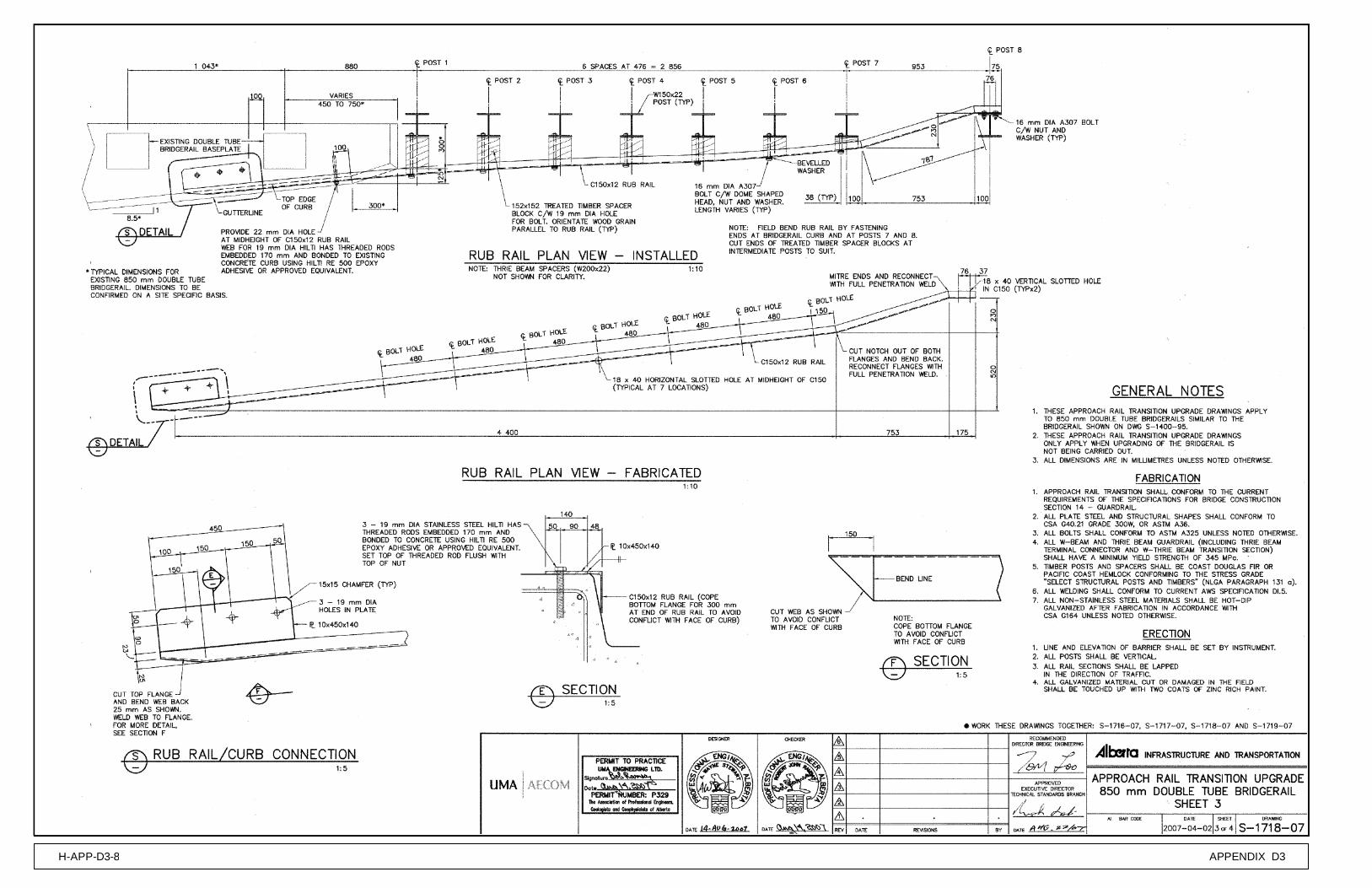
S‐1718‐07 Approach Rail Transition Upgrade 850 mm Double Tube Bridgerail ‐ Sheet 3 H‐APP‐D3‐8
S‐1719‐07 Approach Rail Transition Upgrade 850 mm Double Tube Bridgerail ‐ Sheet 4 H‐APP‐D3‐9
S‐1720‐07 Deep Beam (W‐Beam) Bridgerail And Approach Rail Transition Upgrade Details H‐APP‐D3‐10

Alberta Infrastructure and Transportation November 2007 Roadside Design Guide
TABLE OF CONTENTS APPENDIX D3-ii
THIS PAGE INTENTIONALLY LEFT BLANK
APPENDIX D3 H-APP-D3-1

APPENDIX D3H-APP-D3-2

APPENDIX D3 H-APP-D3-3

APPENDIX D3H-APP-D3-4

APPENDIX D3 H-APP-D3-5

APPENDIX D3H-APP-D3-6

APPENDIX D3 H-APP-D3-7
APPENDIX D3H-APP-D3-8

APPENDIX D3 H-APP-D3-9

APPENDIX D3H-APP-D3-10