Embed Size (px)
Citation preview
Appendix D:
Geotechnical Investigation, Tentative Tract Number 5928, 1226 Ojai Road, Santa Paula, CA,
RMA GeoScience, March 12, 2014.

9854 Glenoaks Boulevard | Sun Valley, California 91352 | T: 800.762.4396
March 12, 2014 RMA Project Number 13-G72-0 Williams Homes 21080 Centre Pointe Pkwy. #102 Santa Clarita, CA 91350 Attention: Mr. Scott Smith
Subject: Geotechnical Investigation
Tentative Tract Number 5928 1226 Ojai Road Santa Paula, CA
Dear Mr. Smith, In accordance with your request, a geotechnical investigation has been completed for the above-referenced project. The
report addresses both engineering geologic and geotechnical conditions. The results of the investigation are presented in
the accompanying report, which includes a description of site conditions, results of our field exploration and laboratory
testing, conclusions, and recommendations.
We appreciate this opportunity to be of service to you. If you have any questions regarding this report, please do not hesitate to contact us at your convenience. Respectfully submitted, RMA GeoScience
Marlon Jones, PE Mark Swiatek, RG/CEG Principal Engineer Principal Geologist

GEOTECHNICAL INVESTIGATION SANTA PAULA - OJAI ROAD
TENTATIVE TRACT 5928 SANTA PAULA, CALIFORNIA
For
Williams Homes 21080 Centre Pointe Pkwy. #102
Santa Clarita, CA 91350
March 12, 2014
Project No. 13-G72-0
Santa Paula – Ojai Road March 12, 2014 Williams Homes RMA Project No.: 13-G72-0 Page i
TABLE OF CONTENTS
1.0 INTRODUCTION ................................................................................................................................................. 1
1.01 PURPOSE ....................................................................................................................................................................... 1 1.02 SCOPE OF THE INVESTIGATION ..................................................................................................................................... 1 1.03 SITE LOCATION AND DESCRIPTION .............................................................................................................................. 1 1.04 PAST LAND USAGE ....................................................................................................................................................... 1 1.05 PLANNED DEVELOPMENT ............................................................................................................................................ 1 1.06 INVESTIGATION METHODS ........................................................................................................................................... 2
2.0 FINDINGS ............................................................................................................................................................. 2
2.01 GEOLOGIC SETTING ..................................................................................................................................................... 2 2.02 EARTH MATERIALS ....................................................................................................................................................... 2 2.03 EXPANSIVE SOILS.......................................................................................................................................................... 3 2.04 SURFACE AND GROUNDWATER CONDITIONS ............................................................................................................... 3 2.05 FAULTS ......................................................................................................................................................................... 3 2.06 LANDSLIDES ................................................................................................................................................................. 3 2.07 LIQUEFACTION ............................................................................................................................................................. 3 2.08 SLOPE STABILITY .......................................................................................................................................................... 4
3.0 CONCLUSIONS AND RECOMMENDATIONS ................................................................................................. 4
3.01 GENERAL CONCLUSION ................................................................................................................................................ 4 3.02 GENERAL EARTHWORK AND GRADING ........................................................................................................................ 4 3.03 EARTHWORK SHRINKAGE AND SUBSIDENCE ................................................................................................................ 4 3.04 REMOVALS AND OVEREXCAVATION ............................................................................................................................. 4 3.05 SLOPES .......................................................................................................................................................................... 5 3.06 SEISMIC DESIGN PARAMETERS ...................................................................................................................................... 5 3.07 FOUNDATIONS .............................................................................................................................................................. 6 3.08 SLABS ON GRADE .......................................................................................................................................................... 8 3.09 MISCELLANEOUS CONCRETE FLATWORK ...................................................................................................................... 9 3.10 FOOTING EXCAVATION AND SLAB PREPARATIONS ....................................................................................................... 9 3.11 CEMENT TYPE AND CORROSION POTENTIAL .............................................................................................................. 10 3.12 UTILITY TRENCH BACKFILL ........................................................................................................................................ 11 3.13 DRAINAGE .................................................................................................................................................................. 11 3.14 PLAN REVIEW ............................................................................................................................................................. 11 3.15 GEOTECHNICAL OBSERVATION AND TESTING DURING ROUGH GRADING ................................................................ 11 3.16 POST-GRADING GEOTECHNICAL OBSERVATION AND TESTING ................................................................................. 12
4.0 CLOSURE ............................................................................................................................................................. 12
FIGURES AND TABLES Figure 1 Site Location Map Figure 2 Typical Stabilization Fill Design Plate 1 Geologic Map Plate 2 Geologic Cross Sections APPENDICES Appendix A Field Investigation A1 Appendix B Laboratory Tests B1

Santa Paula – Ojai Road March 12, 2014 Williams Homes RMA Project No.: 13-G72-0 Page ii
Appendix C General Earthwork and Grading Specifications C1 Appendix D References D1
Santa Paula – Ojai Road March 12, 2014 Williams Homes RMA Project No.: 13-G72-0 Page 1
1.0 Introduction
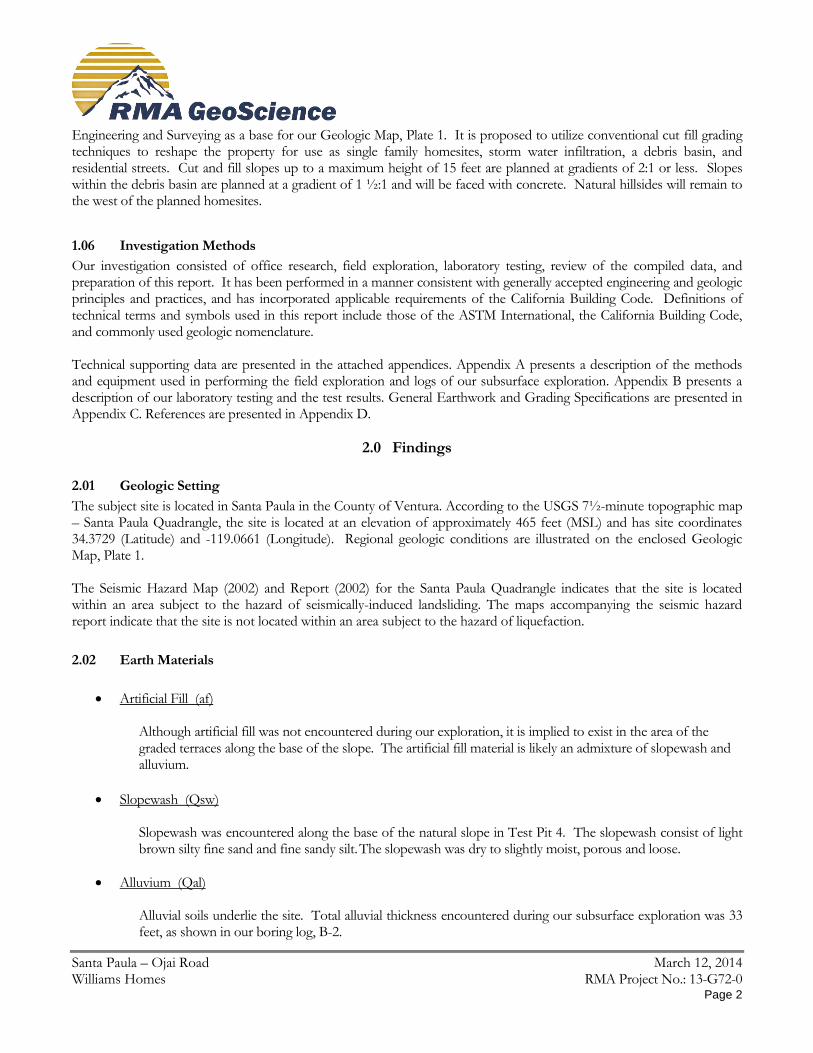
1.01 Purpose
A geotechnical investigation has been completed at the subject site. The purpose of the investigation was to summarize geotechnical and geologic conditions at the site, to assess their potential impact on the proposed development, and to develop geotechnical and engineering geologic design parameters.
1.02 Scope of the Investigation
The general scope of this investigation included the following:
Review of published and unpublished geologic, seismic, groundwater, and geotechnical literature.
Examination of aerial photographs and topographic maps.
Contacting of Underground Service Alert (USA) to locate onsite utility lines.
Logging, sampling, and backfilling of eight (8) exploratory borings drilled with a CME-75 drill rig.
Laboratory testing of representative soil samples.
Geotechnical evaluation of the compiled data.
Preparation of this report presenting our findings, conclusions, and recommendations.
Our scope of work did not include a preliminary site assessment for the potential of hazardous materials onsite.
1.03 Site Location and Description
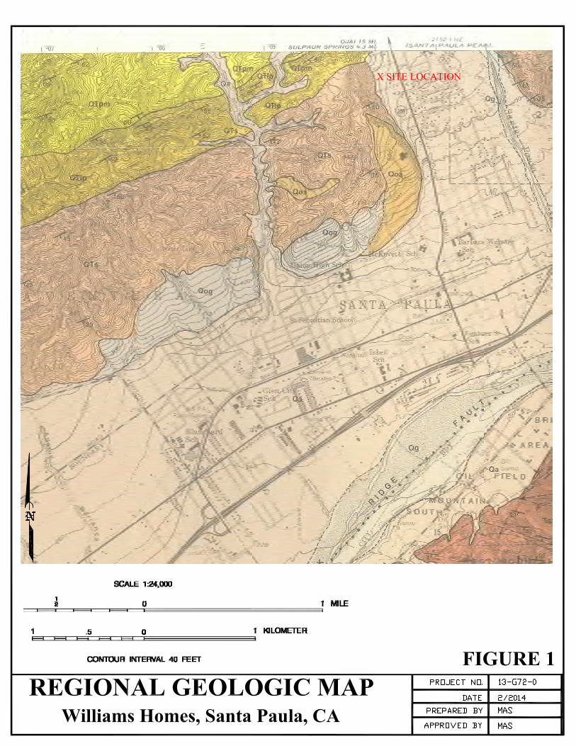
The subject property consists of approximately 20 acres of land located in Santa Paula, California. The site is situated along Ojai Road between Oakdale and Royal Oaks Street (Fig. 1). Currently, a single family residence and associated buildings exist on the site. However, only the single family residence will remain after the proposed construction as the other buildings will be demolished. The site is situated below a prominent north south trending ridge. Natural slopes up to 300 feet in height exist above and to the west of the planned development at gradients of 2:1 or flatter. The area planned for development is located within the natural drainage course for Santa Paula Creek. A zone approximately 100’ wide along the base of the slope has been modified by grading. There are at least four, low height graded terraces with rock walls located along the toe of the natural slope. There is also a water storage tank located along the base of the slope in the northwest corner of the site that is not shown on the survey.
1.04 Past Land Usage
Based on our review of aerial photographs, topographic maps, and our research we conclude that the area was used for residential and agricultural purposes in the past. Concrete irrigation pipes and risers were observed across the site. The open fields are fenced and are currently being used to board horses. No other past uses were identified for the property.
1.05 Planned Development
It is currently planned to develop the subject site for use as single family home sites. The tentative tract map is being prepared by Southland Civil Engineering and Survey, LLP. We have utilized the plan prepared by Southland Civil
Santa Paula – Ojai Road March 12, 2014 Williams Homes RMA Project No.: 13-G72-0 Page 2
Engineering and Surveying as a base for our Geologic Map, Plate 1. It is proposed to utilize conventional cut fill grading techniques to reshape the property for use as single family homesites, storm water infiltration, a debris basin, and residential streets. Cut and fill slopes up to a maximum height of 15 feet are planned at gradients of 2:1 or less. Slopes within the debris basin are planned at a gradient of 1 ½:1 and will be faced with concrete. Natural hillsides will remain to the west of the planned homesites.
1.06 Investigation Methods
Our investigation consisted of office research, field exploration, laboratory testing, review of the compiled data, and preparation of this report. It has been performed in a manner consistent with generally accepted engineering and geologic principles and practices, and has incorporated applicable requirements of the California Building Code. Definitions of technical terms and symbols used in this report include those of the ASTM International, the California Building Code, and commonly used geologic nomenclature. Technical supporting data are presented in the attached appendices. Appendix A presents a description of the methods and equipment used in performing the field exploration and logs of our subsurface exploration. Appendix B presents a description of our laboratory testing and the test results. General Earthwork and Grading Specifications are presented in Appendix C. References are presented in Appendix D.
2.0 Findings
2.01 Geologic Setting
The subject site is located in Santa Paula in the County of Ventura. According to the USGS 7½-minute topographic map – Santa Paula Quadrangle, the site is located at an elevation of approximately 465 feet (MSL) and has site coordinates 34.3729 (Latitude) and -119.0661 (Longitude). Regional geologic conditions are illustrated on the enclosed Geologic Map, Plate 1. The Seismic Hazard Map (2002) and Report (2002) for the Santa Paula Quadrangle indicates that the site is located within an area subject to the hazard of seismically-induced landsliding. The maps accompanying the seismic hazard report indicate that the site is not located within an area subject to the hazard of liquefaction.
2.02 Earth Materials
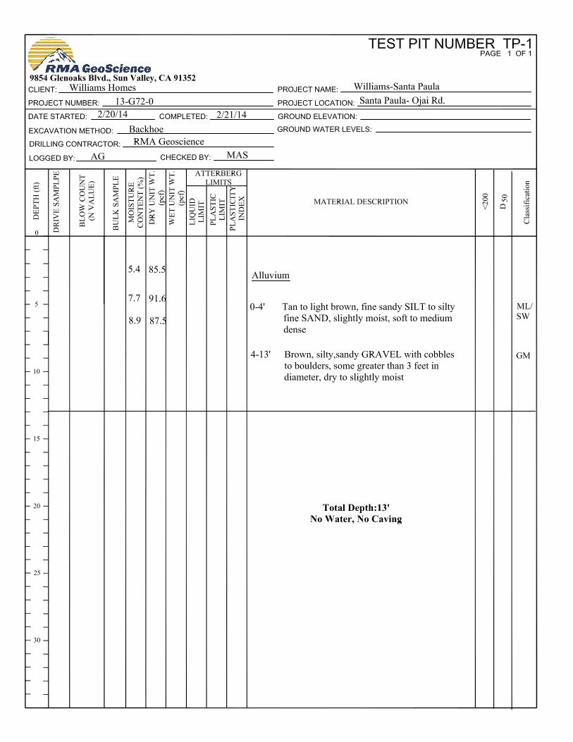
Artificial Fill (af) Although artificial fill was not encountered during our exploration, it is implied to exist in the area of the graded terraces along the base of the slope. The artificial fill material is likely an admixture of slopewash and alluvium.
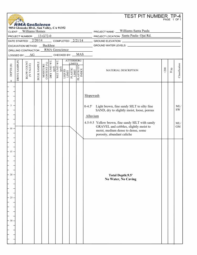
Slopewash (Qsw)
Slopewash was encountered along the base of the natural slope in Test Pit 4. The slopewash consist of light brown silty fine sand and fine sandy silt. The slopewash was dry to slightly moist, porous and loose.
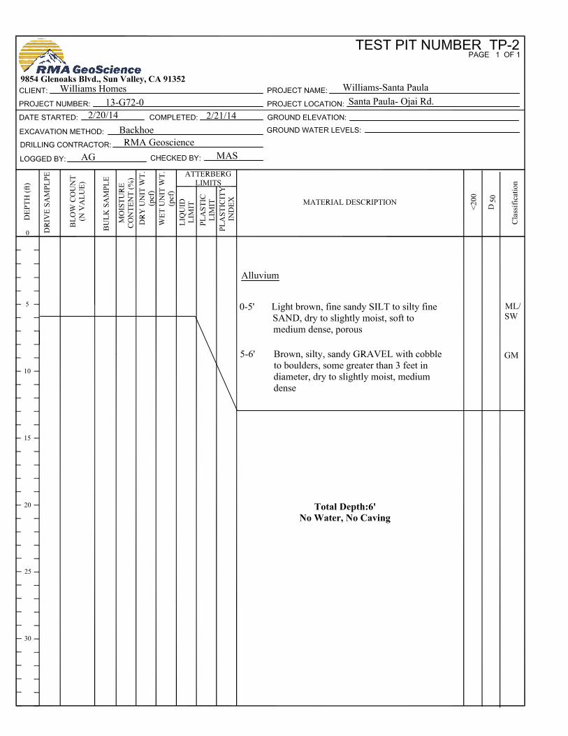
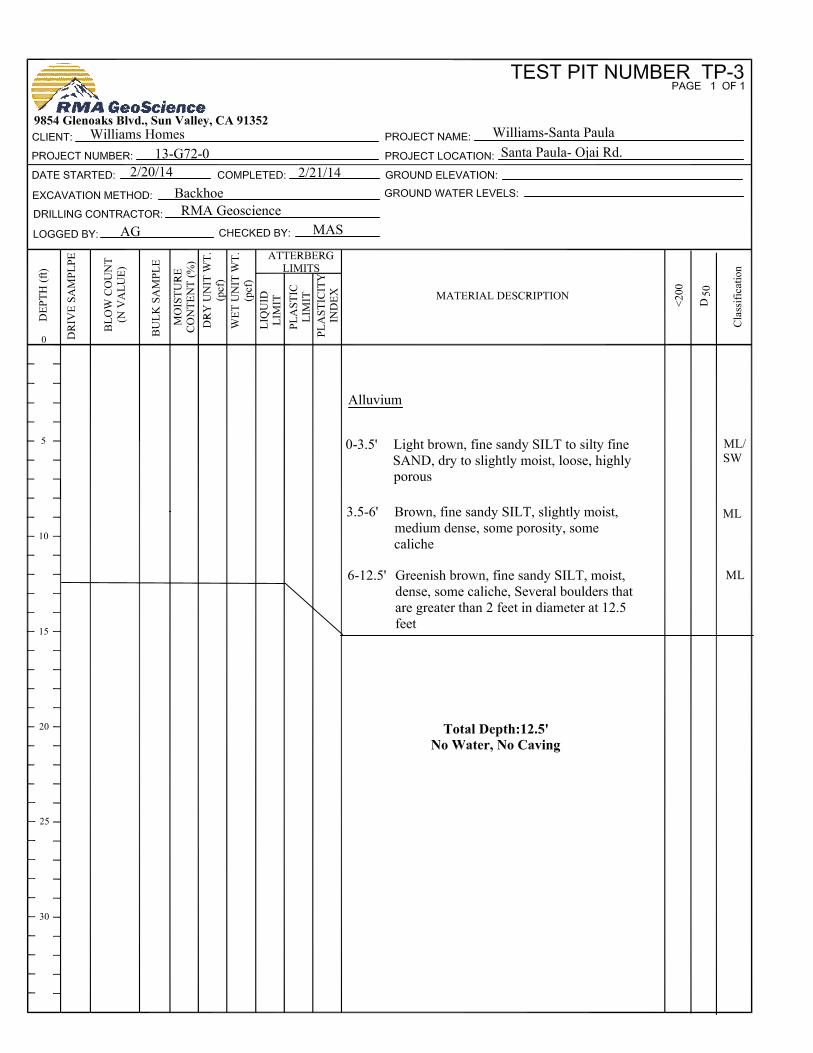
Alluvium (Qal)
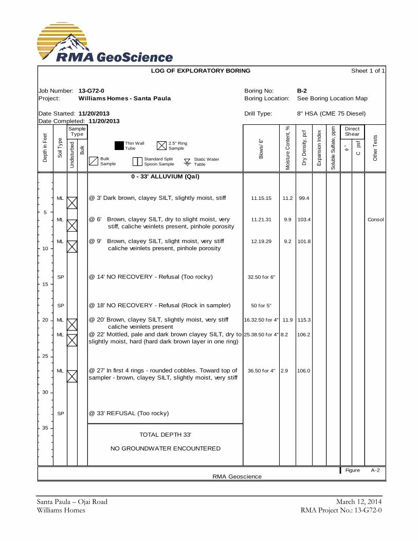
Alluvial soils underlie the site. Total alluvial thickness encountered during our subsurface exploration was 33 feet, as shown in our boring log, B-2.
Santa Paula – Ojai Road March 12, 2014 Williams Homes RMA Project No.: 13-G72-0 Page 3
Generally, the alluvium consists of multilayers of medium dense silts with various amounts of clays and sands in the upper 5 to 6 feet. Below 6 feet, the alluvium becomes rocky and cobbly. The soils in the upper five feet of the site are soft, slightly moist, and potentially compressible. These soils are not suitable for structural support and should be removed and recompacted prior to construction.
Bedrock : Saugus Fm (QTs).
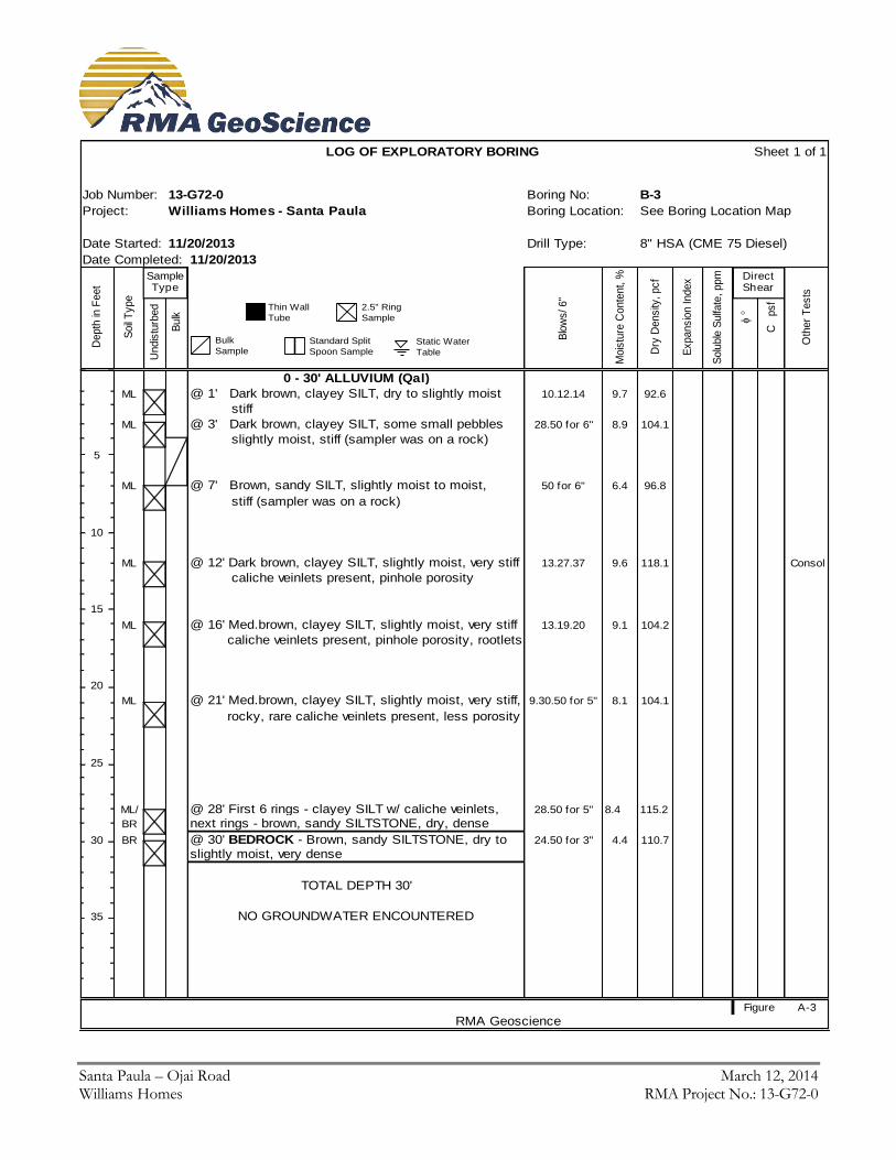
In the hillsides and below the alluvium on the site, the bedrock consists, generally, of thinly bedded, brown sandy, siltstone. Bedrock is slightly moist to moist and dense. Bedding planes are striking in an east northeast direction with dips towards the southeast at moderate to steep angles. Bedrock was encountered in Boring B-3 at a depth of 30 feet below the existing ground surface.
The subsurface soils encountered in the exploratory borings drilled at the site are described in greater detail on the logs contained in Appendix A.
2.03 Expansive Soils
It is anticipated that the soils at the site will be re-distributed during re-grading operations. Based on our preliminary testing, we anticipate that the soils which will ultimately support the proposed building foundations will have a medium expansion index. Additional expansion index and plasticity index testing will be required at the completion of grading to verify the properties of the near surface soils prior to the final design and construction of the foundation system for the proposed structures.
2.04 Surface and Groundwater Conditions
Groundwater was not encountered during our subsurface exploration. Near surface groundwater is not expected to exist within the site boundaries.
2.05 Faults
The site is not located within the boundaries of an Earthquake Fault Zone for fault-rupture hazard as defined by the Alquist-Priolo Earthquake Fault Zoning Act and no active faults are known to pass through the property. The nearest earthquake fault zone is located about 5 miles to the south of the site along the Oak Ridge fault.
2.06 Landslides
According to the Seismic Hazard Zones Map for the Santa Paula Quadrangle (2002), the site is situated within a Landslide Hazard Zone. The orientation of the bedding planes is favorable with respect to the gross stability of the slopes. They were no landslides observed during reconnaissance of the site, on regional geologic maps or aerial site photographs.
2.07 Liquefaction
According to the Seismic Hazard Zones Map for the Santa Paula Quadrangle (2002), the site is not situated within a Liquefaction Hazard Zone. Additionally, historic high groundwater is anticipated to be greater than 40 feet below existing grade. Therefore, liquefaction and related phenomena (i.e. seismically-induced settlement, lateral spreading, lateral flows, bearing strength loss, sand boils, etc…) are not anticipated to impact the site.
Santa Paula – Ojai Road March 12, 2014 Williams Homes RMA Project No.: 13-G72-0 Page 4
2.08 Slope Stability
The relationship between the hillside and the development are illustrated on Geologic Cross A and B. The orientation of the bedding planes is favorable with respect to the gross stability of the slope. A debris basin is planned to intercept any runoff or shallow debris slides which could occur in the natural slope areas.
3.0 Conclusions and Recommendations
3.01 General Conclusion
Based on specific data and information contained in this report, our understanding of the project and our general experience in engineering geology and geotechnical engineering, it is our professional judgment that the proposed development is geologically and geotechnically feasible. This is provided that the recommendations presented below are fully implemented during design, grading and construction. It is anticipated that large diameter boulders will be encountered to the depths of the planned overexcavation. Large boulders should be hauled off the site or utilized for landscaping purposes. Large boulders MAY pose problems for underground utilities that might exist at depths below the recommended overexcavation.
3.02 General Earthwork and Grading
All grading should be performed in accordance with the General Earthwork and Grading Specifications outlined in Appendix C, unless specifically revised or amended below. Recommendations contained in Appendix C are general specifications for typical grading projects and may not be entirely applicable to this project. It is also recommended that all earthwork and grading be performed in accordance with Appendix J of the 2013 California Building Code (CBC) and all applicable governmental agency requirements. In the event of conflicts between this report and CBC Appendix J, this report shall govern.
3.03 Earthwork Shrinkage and Subsidence
Shrinkage is the decrease in volume of soil upon removal and recompaction expressed as a percentage of the original in-place volume. Subsidence occurs as natural ground is densified to receive fill. These factors account for changes in earth volumes that will occur during grading. Our estimates are as follows:
Shrinkage factor = 15-18% for soil removed and replaced as compacted fill.
Subsidence factor = 0.1 foot.
The degree to which fill soils are compacted and variations in the in-situ density of existing soils will influence earth volume changes. Consequently, some adjustments in grades near the completion of grading could be required to balance the earthwork.
3.04 Removals and Overexcavation
All vegetation, trash and debris should be cleared from the grading area and removed from the site. Prior to placement of compacted fills, all non-engineered fills and loose, porous, or compressible soils will need to be removed down to competent ground. Removal and requirements will also apply to cut areas, if the depth of cut is not sufficient to reach competent ground. Removed and/or overexcavated soils may be moisture-conditioned and recompacted as engineered fill, except for soils containing detrimental amounts of organic material. Estimated depths of removals are as follows:
Santa Paula – Ojai Road March 12, 2014 Williams Homes RMA Project No.: 13-G72-0 Page 5
As mentioned in Section 2.02, soft, porous, and compressible native soils were encountered to depths of
about 5 to 7 feet below existing grades. The average depth of removal of these soils is expected to be 6 feet
with some local areas extending to 8 feet below the existing ground surface.
Soils disturbed by demolition of existing structures will need to be over-excavated to competent native ground
and then scarified to a minimum depth of 12 inches, moisture conditioned and compacted to at least 90
percent of the maximum dry density. In addition to the above requirements, overexcavation will also need to meet the following criteria for the building pads, concrete flatwork, and pavement areas:
All footing areas, both continuous and spread, shall be undercut, moistened, and compacted as necessary to
produce soils compacted to a minimum of 90% relative compaction to a depth equal to the width of the footing
below the bottom of the footing or to a depth of 3 feet below the bottom of the footing, whichever is less.
Footing areas shall be defined as the area extending from the edge of the footing for a distance of 5 feet.
All floor slabs, concrete flatwork, and paved areas shall be underlain by a minimum of 12 inches of soil
compacted to a minimum of 90% relative compaction.
The exposed soils beneath all overexcavation should be scarified an additional 12 inches, moisture conditioned and compacted to a minimum of 90% relative compaction. The above recommendations are based on the assumption that soils encountered during field exploration are representative of soils throughout the site. However, there can be unforeseen and unanticipated variations in soils between points of subsurface exploration. Hence, overexcavation depths must be verified, and adjusted if necessary, at the time of grading. The overexcavated materials may be moisture-conditioned and re-compacted as engineered fill.
3.05 Slopes
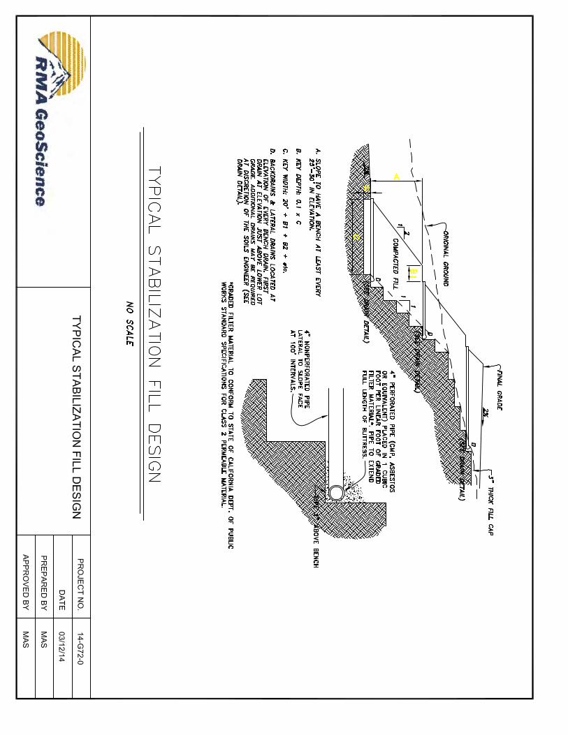
Graded Slopes All planned cut slopes and the cut portion of cut over fill slopes should be completely overexcavated and rebuilt to grade as a stabilization fill slope. A typical stabilization fill slope detail is presented on Figure 2. Natural Slopes It is currently planned to construct an 8 foot wide concrete interceptor drain between the graded slopes and natural slopes. It is our recommendation to construct the interceptor drain with a minimum of 30 inches of freeboard designed as a retaining wall for an equivalent fluid pressure of 45 pcf. The concrete interceptor drain will require periodic maintenance.
3.06 Seismic Design Parameters
Seismic design parameters have been developed in accordance with Section 1613 of the 2013 California Building Code (CBC) using the online U.S. Geological Survey Seismic Design Maps Calculator (Version 3.1.0, ASCE 10 Standard) and a site location based on latitude and longitude. The calculator generates probabilistic and deterministic maximum considered earthquake spectral parameters represented by a 5-percent damped acceleration response spectrum having a 2-percent probability of exceedence in 50 years. The deterministic response accelerations are calculated as 150
Santa Paula – Ojai Road March 12, 2014 Williams Homes RMA Project No.: 13-G72-0 Page 6
percent of the largest median 5-percent damped spectral response acceleration computed on active faults within a region, where the deterministic values govern. The calculator does not, however, produce separate probabilistic and deterministic results. The parameters generated for the subject site are presented below:
2013 California Building Code (CBC) Seismic Parameters
Parameter Value
Site Location Latitude = 34.3729 degrees
Longitude = -119.0661 degrees
Site Class Site Class = D
Soil Profile Name Alluvium
Mapped Spectral Accelerations (Site Class B)
Ss (0.2- second period) = 2.319g S1 (1-second period) = 0.915g
Site Coefficients (Site Class D)
Fa = 1.0 Fv = 1.5
Maximum Considered Earthquake Spectral Accelerations (Site Class D)
SMS (0.2- second period) = 2.319g SM1 (1-second period) = 1.372g
Design Earthquake Spectral Accelerations (Site Class D)
SDS (0.2- second period) = 1.546g SD1 (1-second period) = 0.915g
The above table shows that the mapped spectral response acceleration parameter, a 1-second period, (S1) > 0.75g. Therefore, for Risk Categories I, II and II the Seismic Design Category is E (CBC Table 1604.5 and Section 1613.3.5). Consequently, as required for Seismic Design Categories C through F by CBC Section 1803.5.11, the following geologic and seismic hazards have been evaluated: slope instability in Section 2.07, liquefaction in Section 2.08, total and differential settlement in Sections 3.06, and surface displacement by faulting or seismically-induced lateral spreading or lateral flow in Sections 2.05 and 2.08. Applicable portions of CBC Section 1803.5.12 have been included in evaluation of the above listed geologic and seismic hazards. Peak earthquake ground acceleration adjusted for site class effects (PGAM) has been determine in accordance with ASCE 7-10 Section 11.8.3 as follows: PGAM = FPGA x PGA = 1.000 x 0.883g = 0.883g.
3.07 Foundations
It is anticipated that the primary mechanisms for differential movement of building foundations at the subject site will be shrinkage and swelling of expansive soils. Post-tensioned foundations and slabs can be used to mitigate the effects of expansive soils. It should also be noted that the foundation designs provided herein for expansive soils will be sufficient to mitigate potential settlement associated with the alluvium underlying the fill on the site. The following parameters can be used for preliminary design purposes. Please note that additional testing will be performed at the completion of site grading to confirm/verify the expansion potential of the near surface soils. Revisions to these design parameters may be necessary. Post Tensioned Slab: It is recommended that the design provide for a stiff floor slab, which minimizes the amount of deflection imposed on the structure. The slab and foundation system should be designed in accordance with the recommendations contained in the PTI Standard Requirements for Design of Shallow Post-Tensioned Concrete Foundations on Expansive Soils by a foundation design engineer experienced in the field of slab design. The slab designer should provide
Santa Paula – Ojai Road March 12, 2014 Williams Homes RMA Project No.: 13-G72-0 Page 7
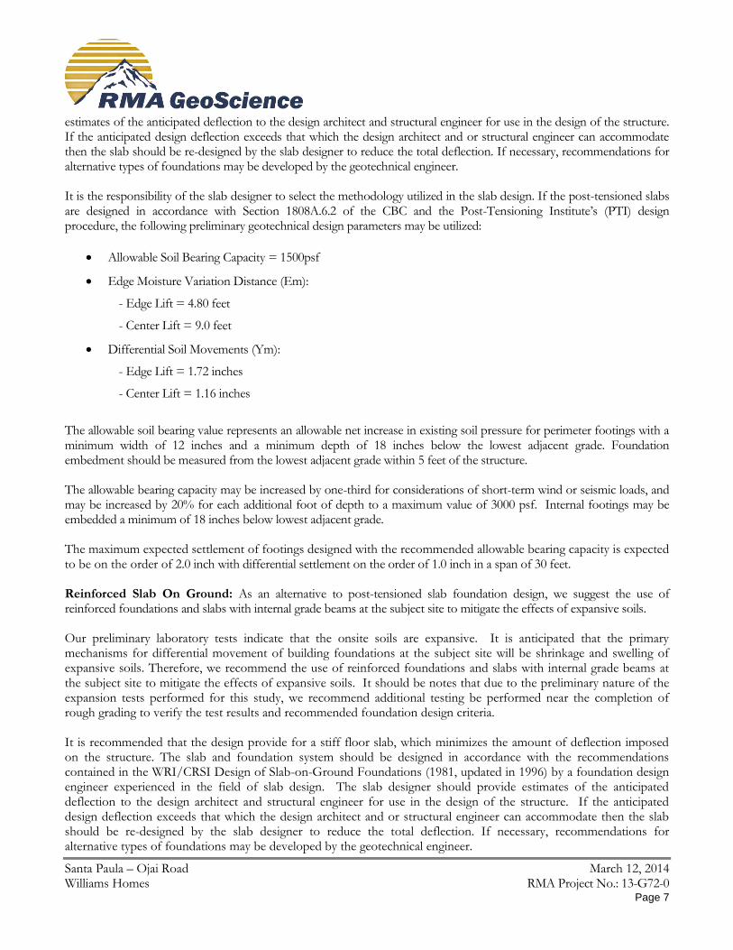
estimates of the anticipated deflection to the design architect and structural engineer for use in the design of the structure. If the anticipated design deflection exceeds that which the design architect and or structural engineer can accommodate then the slab should be re-designed by the slab designer to reduce the total deflection. If necessary, recommendations for alternative types of foundations may be developed by the geotechnical engineer. It is the responsibility of the slab designer to select the methodology utilized in the slab design. If the post-tensioned slabs are designed in accordance with Section 1808A.6.2 of the CBC and the Post-Tensioning Institute’s (PTI) design procedure, the following preliminary geotechnical design parameters may be utilized:
Allowable Soil Bearing Capacity = 1500psf
Edge Moisture Variation Distance (Em):
- Edge Lift = 4.80 feet
- Center Lift = 9.0 feet
Differential Soil Movements (Ym):
- Edge Lift = 1.72 inches
- Center Lift = 1.16 inches
The allowable soil bearing value represents an allowable net increase in existing soil pressure for perimeter footings with a minimum width of 12 inches and a minimum depth of 18 inches below the lowest adjacent grade. Foundation embedment should be measured from the lowest adjacent grade within 5 feet of the structure. The allowable bearing capacity may be increased by one-third for considerations of short-term wind or seismic loads, and may be increased by 20% for each additional foot of depth to a maximum value of 3000 psf. Internal footings may be embedded a minimum of 18 inches below lowest adjacent grade. The maximum expected settlement of footings designed with the recommended allowable bearing capacity is expected to be on the order of 2.0 inch with differential settlement on the order of 1.0 inch in a span of 30 feet. Reinforced Slab On Ground: As an alternative to post-tensioned slab foundation design, we suggest the use of reinforced foundations and slabs with internal grade beams at the subject site to mitigate the effects of expansive soils. Our preliminary laboratory tests indicate that the onsite soils are expansive. It is anticipated that the primary mechanisms for differential movement of building foundations at the subject site will be shrinkage and swelling of expansive soils. Therefore, we recommend the use of reinforced foundations and slabs with internal grade beams at the subject site to mitigate the effects of expansive soils. It should be notes that due to the preliminary nature of the expansion tests performed for this study, we recommend additional testing be performed near the completion of rough grading to verify the test results and recommended foundation design criteria. It is recommended that the design provide for a stiff floor slab, which minimizes the amount of deflection imposed on the structure. The slab and foundation system should be designed in accordance with the recommendations contained in the WRI/CRSI Design of Slab-on-Ground Foundations (1981, updated in 1996) by a foundation design engineer experienced in the field of slab design. The slab designer should provide estimates of the anticipated deflection to the design architect and structural engineer for use in the design of the structure. If the anticipated design deflection exceeds that which the design architect and or structural engineer can accommodate then the slab should be re-designed by the slab designer to reduce the total deflection. If necessary, recommendations for alternative types of foundations may be developed by the geotechnical engineer.
Santa Paula – Ojai Road March 12, 2014 Williams Homes RMA Project No.: 13-G72-0 Page 8
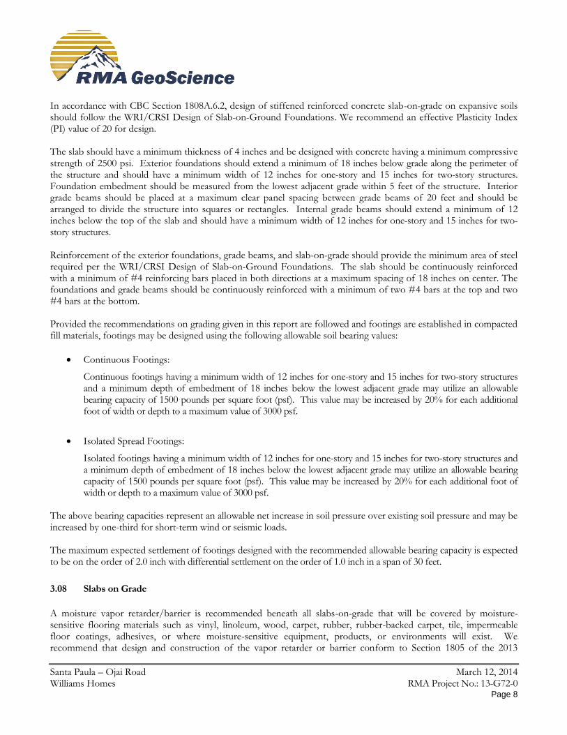
In accordance with CBC Section 1808A.6.2, design of stiffened reinforced concrete slab-on-grade on expansive soils should follow the WRI/CRSI Design of Slab-on-Ground Foundations. We recommend an effective Plasticity Index (PI) value of 20 for design. The slab should have a minimum thickness of 4 inches and be designed with concrete having a minimum compressive strength of 2500 psi. Exterior foundations should extend a minimum of 18 inches below grade along the perimeter of the structure and should have a minimum width of 12 inches for one-story and 15 inches for two-story structures. Foundation embedment should be measured from the lowest adjacent grade within 5 feet of the structure. Interior grade beams should be placed at a maximum clear panel spacing between grade beams of 20 feet and should be arranged to divide the structure into squares or rectangles. Internal grade beams should extend a minimum of 12 inches below the top of the slab and should have a minimum width of 12 inches for one-story and 15 inches for two-story structures. Reinforcement of the exterior foundations, grade beams, and slab-on-grade should provide the minimum area of steel required per the WRI/CRSI Design of Slab-on-Ground Foundations. The slab should be continuously reinforced with a minimum of #4 reinforcing bars placed in both directions at a maximum spacing of 18 inches on center. The foundations and grade beams should be continuously reinforced with a minimum of two #4 bars at the top and two #4 bars at the bottom. Provided the recommendations on grading given in this report are followed and footings are established in compacted fill materials, footings may be designed using the following allowable soil bearing values:
Continuous Footings:
Continuous footings having a minimum width of 12 inches for one-story and 15 inches for two-story structures and a minimum depth of embedment of 18 inches below the lowest adjacent grade may utilize an allowable bearing capacity of 1500 pounds per square foot (psf). This value may be increased by 20% for each additional foot of width or depth to a maximum value of 3000 psf.
Isolated Spread Footings:
Isolated footings having a minimum width of 12 inches for one-story and 15 inches for two-story structures and a minimum depth of embedment of 18 inches below the lowest adjacent grade may utilize an allowable bearing capacity of 1500 pounds per square foot (psf). This value may be increased by 20% for each additional foot of width or depth to a maximum value of 3000 psf.
The above bearing capacities represent an allowable net increase in soil pressure over existing soil pressure and may be increased by one-third for short-term wind or seismic loads. The maximum expected settlement of footings designed with the recommended allowable bearing capacity is expected to be on the order of 2.0 inch with differential settlement on the order of 1.0 inch in a span of 30 feet.
3.08 Slabs on Grade
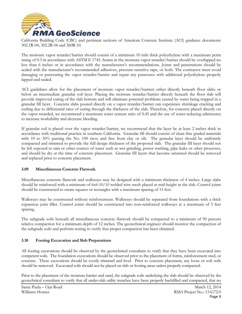
A moisture vapor retarder/barrier is recommended beneath all slabs-on-grade that will be covered by moisture-sensitive flooring materials such as vinyl, linoleum, wood, carpet, rubber, rubber-backed carpet, tile, impermeable floor coatings, adhesives, or where moisture-sensitive equipment, products, or environments will exist. We recommend that design and construction of the vapor retarder or barrier conform to Section 1805 of the 2013
Santa Paula – Ojai Road March 12, 2014 Williams Homes RMA Project No.: 13-G72-0 Page 9
California Building Code (CBC) and pertinent sections of American Concrete Institute (ACI) guidance documents 302.1R-04, 302.2R-06 and 360R-10. The moisture vapor retarder/barrier should consist of a minimum 10 mils thick polyethylene with a maximum perm rating of 0.3 in accordance with ASTM E 1745. Seams in the moisture vapor retarder/barrier should be overlapped no less than 6 inches or in accordance with the manufacturer’s recommendations. Joints and penetrations should be sealed with the manufacturer’s recommended adhesives, pressure-sensitive tape, or both. The contractor must avoid damaging or puncturing the vapor retarder/barrier and repair any punctures with additional polyethylene properly lapped and sealed. ACI guidelines allow for the placement of moisture vapor retarder/barriers either directly beneath floor slabs or below an intermediate granular soil layer. Placing the moisture retarder/barrier directly beneath the floor slab will provide improved curing of the slab bottom and will eliminate potential problems caused by water being trapped in a granular fill layer. Concrete slabs poured directly on a vapor retarder/barrier can experience shrinkage cracking and curling due to differential rates of curing through the thickness of the slab. Therefore, for concrete placed directly on the vapor retarded, we recommend a maximum water cement ratio of 0.45 and the use of water-reducing admixtures to increase workability and decrease bleeding. If granular soil is placed over the vapor retarder/barrier, we recommend that the layer be at least 2 inches thick in accordance with traditional practice in southern California. Granular fill should consist of clean fine graded materials with 10 to 30% passing the No. 100 sieve and free from clay or silt. The granular layer should be uniformly compacted and trimmed to provide the full design thickness of the proposed slab. The granular fill layer should not be left exposed to rain or other sources of water such as wet-grinding, power washing, pipe leaks or other processes, and should be dry at the time of concrete placement. Granular fill layers that become saturated should be removed and replaced prior to concrete placement.
3.09 Miscellaneous Concrete Flatwork
Miscellaneous concrete flatwork and walkways may be designed with a minimum thickness of 4 inches. Large slabs should be reinforced with a minimum of 6x6-10/10 welded wire mesh placed at mid-height in the slab. Control joints should be constructed to create squares or rectangles with a maximum spacing of 15 feet. Walkways may be constructed without reinforcement. Walkways should be separated from foundations with a thick expansion joint filler. Control joints should be constructed into non-reinforced walkways at a maximum of 5 feet spacing. The subgrade soils beneath all miscellaneous concrete flatwork should be compacted to a minimum of 90 percent relative compaction for a minimum depth of 12 inches. The geotechnical engineer should monitor the compaction of the subgrade soils and perform testing to verify that proper compaction has been obtained.
3.10 Footing Excavation and Slab Preparations
All footing excavations should be observed by the geotechnical consultant to verify that they have been excavated into competent soils. The foundation excavations should be observed prior to the placement of forms, reinforcement steel, or concrete. These excavations should be evenly trimmed and level. Prior to concrete placement, any loose or soft soils should be removed. Excavated soils should not be placed on slab or footing areas unless properly compacted. Prior to the placement of the moisture barrier and sand, the subgrade soils underlying the slab should be observed by the geotechnical consultant to verify that all under-slab utility trenches have been properly backfilled and compacted, that no
Santa Paula – Ojai Road March 12, 2014 Williams Homes RMA Project No.: 13-G72-0 Page 10
loose or soft soils are present, and that the slab subgrade has been properly compacted to a minimum of 90 percent relative compaction within the upper 12 inches.
Footings may experience and overall loss in bearing capacity or an increased potential to settle where located in close proximity to existing or future utility trenches. Furthermore, stresses imposed by the footings on the utility lines may cause cracking, collapse and/or a loss of serviceability. To reduce this risk, footings should extend below a 1:1 plane projected upward from the closest bottom of the trench. Slabs on grade and walkways should be brought to a minimum of 2% and a maximum of 6% above their optimum moisture content for a depth of 18 inches prior to the placement of concrete. The geotechnical consultant should perform in-situ moisture tests to verify that the appropriate moisture content has been achieved a maximum of 24 hours prior to the placement of concrete or moisture barriers.
3.11 Cement Type and Corrosion Potential
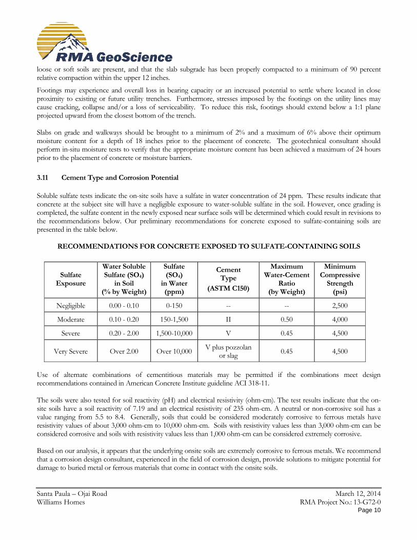
Soluble sulfate tests indicate the on-site soils have a sulfate in water concentration of 24 ppm. These results indicate that concrete at the subject site will have a negligible exposure to water-soluble sulfate in the soil. However, once grading is completed, the sulfate content in the newly exposed near surface soils will be determined which could result in revisions to the recommendations below. Our preliminary recommendations for concrete exposed to sulfate-containing soils are presented in the table below.
RECOMMENDATIONS FOR CONCRETE EXPOSED TO SULFATE-CONTAINING SOILS
Sulfate Exposure
Water Soluble Sulfate (SO4)
in Soil (% by Weight)
Sulfate (SO4)
in Water (ppm)
Cement Type
(ASTM C150)
Maximum Water-Cement
Ratio (by Weight)
Minimum Compressive
Strength (psi)
Negligible 0.00 - 0.10 0-150 -- -- 2,500
Moderate 0.10 - 0.20 150-1,500 II 0.50 4,000
Severe 0.20 - 2.00 1,500-10,000 V 0.45 4,500
Very Severe Over 2.00 Over 10,000 V plus pozzolan
or slag 0.45 4,500
Use of alternate combinations of cementitious materials may be permitted if the combinations meet design recommendations contained in American Concrete Institute guideline ACI 318-11. The soils were also tested for soil reactivity (pH) and electrical resistivity (ohm-cm). The test results indicate that the on-site soils have a soil reactivity of 7.19 and an electrical resistivity of 235 ohm-cm. A neutral or non-corrosive soil has a value ranging from 5.5 to 8.4. Generally, soils that could be considered moderately corrosive to ferrous metals have resistivity values of about 3,000 ohm-cm to 10,000 ohm-cm. Soils with resistivity values less than 3,000 ohm-cm can be considered corrosive and soils with resistivity values less than 1,000 ohm-cm can be considered extremely corrosive. Based on our analysis, it appears that the underlying onsite soils are extremely corrosive to ferrous metals. We recommend that a corrosion design consultant, experienced in the field of corrosion design, provide solutions to mitigate potential for damage to buried metal or ferrous materials that come in contact with the onsite soils.
Santa Paula – Ojai Road March 12, 2014 Williams Homes RMA Project No.: 13-G72-0 Page 11
3.12 Utility Trench Backfill
The onsite fill soils will not be suitable for use as pipe bedding for buried utilities. All pipes should be bedded in a sand, gravel or crushed aggregate imported material complying with the requirements of the Standard Specifications for Public Works Construction Section 306-1.2.1. Crushed rock products that do not contain appreciable fines should not be utilized as pipe bedding and/or backfill. Bedding materials should be densified to at least 90% relative compaction (ASTM D1557) by mechanical methods. The geotechnical consultant should review and approve of proposed bedding materials prior to use. All utility trench backfill within street right of way, utility easements, under or adjacent to sidewalks, driveways, or building pads should be observed and tested by the geotechnical consultant to verify proper compaction. Trenches excavated adjacent to foundations should not extend within the footing influence zone defined as the area within a line projected at a 1:1 drawn from the bottom edge of the footing. Trenches crossing perpendicular to foundations should be excavated and backfilled prior to the construction of the foundations. The excavations should be backfilled in the presence of the geotechnical engineer and tested to verify adequate compaction beneath the proposed footing. Cal/OSHA construction safety orders should be observed during all underground work.
3.13 Drainage
Surface drainage should be directed away from the proposed structures into suitable drainage devices. Neither excess irrigation nor rainwater should be allowed to collect or pond against building foundations or within low-lying or level areas of the property. Surface waters should be diverted away from the tops of slopes and prevented from draining over the top of slopes and down the slope face.
3.14 Plan Review
Once a formal grading and foundation plans are prepared for the subject property, this office should review the plans from a geotechnical viewpoint, comment on changes from the plan used during preparation of this report and revise the recommendations of this report where necessary.
3.15 Geotechnical Observation and Testing During Rough Grading
The geotechnical engineer should be contacted to provide observation and testing during the following stages of grading:
During the clearing and grubbing of the site.
During the demolition of any existing structures, buried utilities or other existing improvements.
During excavation and overexcavation of compressible soils.
During all phases of grading including ground preparation and filling operations.
When any unusual conditions are encountered during grading. A final geotechnical report summarizing conditions encountered during grading should be submitted upon completion of the rough grading operations.
Santa Paula – Ojai Road March 12, 2014 Williams Homes RMA Project No.: 13-G72-0 Page 12
3.16 Post-Grading Geotechnical Observation and Testing
After the completion of grading the geotechnical engineer should be contacted to provide additional observation and testing during the following construction activities:
During trenching and backfilling operations of buried improvements and utilities to verify proper backfill and compaction of the utility trenches.
After excavation and prior to placement of reinforcing steel or concrete within footing trenches to verify that footings are properly founded in competent materials.
During fine or precise grading involving the placement of any fills underlying driveways, sidewalks, walkways, or other miscellaneous concrete flatwork to verify proper placement, mixing and compaction of fills.
When any unusual conditions are encountered during construction.
4.0 Closure
The findings, conclusions and recommendations in this report were prepared in accordance with generally accepted engineering and geologic principles and practices. No other warranty, either expressed or implied, is made. This report has been prepared MV Bella Vista LP to be used solely for design purposes. Anyone using this report for any other purpose must draw their own conclusions regarding required construction procedures and subsurface conditions. The geotechnical and geologic consultant should be retained during the earthwork and foundation phases of construction to monitor compliance with the design concepts and recommendations and to provide additional recommendations as needed. Should subsurface conditions be encountered during construction that are different from those described in this report, this office should be notified immediately so that our recommendations may be re-evaluated.

FIGURES AND TABLES

APPENDIX A FIELD INVESTIGATION
Santa Paula – Ojai Road March 12, 2014 Williams Homes RMA Project No.: 13-G72-0
Page A - 1
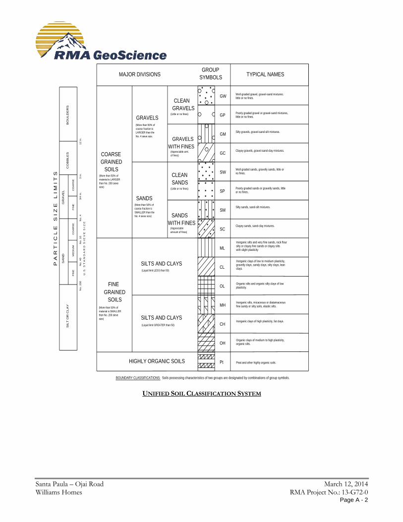
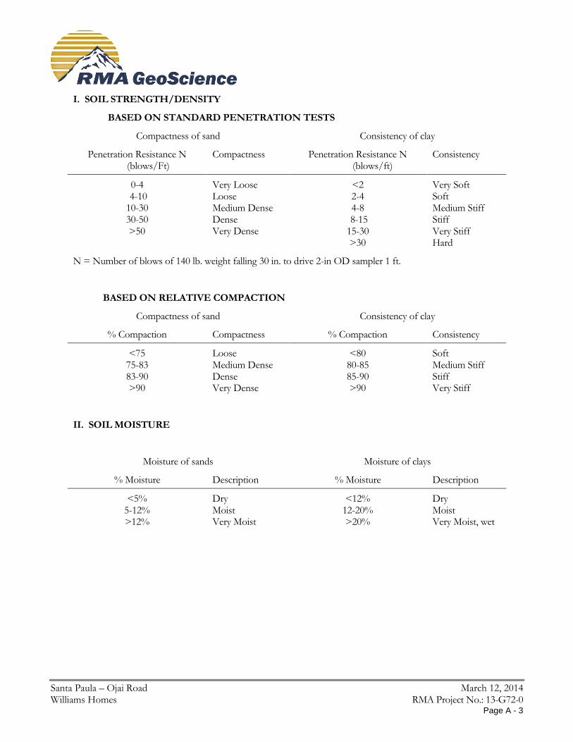
APPENDIX A FIELD INVESTIGATION A-1.00 FIELD EXPLORATION A-1.01 Number of Borings Our subsurface investigation consisted of eight (8) borings drilled with a hollow stem drill rig. A-1.02 Location of Borings A Geologic Map showing the approximate locations of the borings is presented as Plate 1. A-1.03 Boring Logging Logs of borings were prepared by one of our staff and are attached in this appendix. The logs contain factual information and interpretation of subsurface conditions between samples. The strata indicated on these logs represent the approximate boundary between earth units and the transition may be gradual. The logs show subsurface conditions at the dates and locations indicated, and may not be representative of subsurface conditions at other locations and times. Identification of the soils encountered during the subsurface exploration was made using the field identification procedure of the Unified Soils Classification System (ASTM D2488). A legend indicating the symbols and definitions used in this classification system and a legend defining the terms used in describing the relative compaction, consistency or firmness of the soil are attached in this appendix. Bag samples of the major earth units were obtained for laboratory inspection and testing, and the in-place density of the various strata encountered in the exploration was determined.
Santa Paula – Ojai Road March 12, 2014 Williams Homes RMA Project No.: 13-G72-0
Page A - 2
Well graded gravel, gravel-sand mixtures.
Poorly graded gravel or gravel-sand mixtures,
Silty gravels, gravel-sand-silt mixtures.
Clayey gravels, gravel-sand-clay mixtures.
Well graded sands, gravelly sands, little or
Poorly graded sands or gravelly sands, little
Inorganic silts and very fine sands, rock flour
silty or clayey fine sands or clayey silts
Inorganic clays of low to medium plasticity,gravelly clays, sandy clays, silty clays, lean
Organic silts and organic silty clays of low
Inorganic silts, micaceous or diatamaceous
fine sandy or silty soils, elastic silts.
Inorganic clays of high plasticity, fat clays.
Organic clays of medium to high plasticity,
BOUNDARY CLASSIFICATIONS: Soils possessing characteristics of two groups are designated by combinations of group symbols.
Pt
OH
CH
MH
OL
CL
ML
SC
SM
SP
SW
GC
GM
GP
GW
MAJOR DIVISIONSGROUP
SYMBOLSTYPICAL NAMES
CLEAN
GRAVELS
GRAVELS
WITH FINES
GRAVELS
COARSE
GRAINED
SOILS
SANDS
CLEAN
SANDS
SANDS
WITH FINES
SILTS AND CLAYS
SILTS AND CLAYS
FINE
GRAINED
SOILS
HIGHLY ORGANIC SOILS
(More than 50% of
material is LARGER
than No. 200 sieve
size)
(More than 50% of
coarse fraction is
LARGER than the
No. 4 sieve size.
(More than 50% of
coarse fraction is
SMALLER than the
No. 4 sieve size)
(Appreciable
amount of fines)
(Little or no fines)
(Appreciable amt.
of fines)
(Little or no fines)
(More than 50% of
material is SMALLER
than No. 200 sieve
size)
(Liquid limit LESS than 50)
(Liquid limit GREATER than 50)
little or no fines.
little or no fines.
no fines.
or no fines.
Silty sands, sand-silt mixtures.
Clayey sands, sand-clay mixtures.
with slight plasticity
clays.
plasticity.
organic silts.
Peat and other highly organic soils.
P A
R T
I C
L E
S
I Z
E L
I M
I T
S
SIL
T O
R C
LA
Y
SA
ND
GR
AV
EL
CO
BB
LE
SB
OU
LD
ER
S
U. S
. S
T A
N D
A R
D S
I E
V E
S
I Z
E
FIN
EM
ED
IUM
CO
AR
SE
FIN
EC
OA
RS
E
No.
200
No.
40
No.
10
No.
43/4
in.
3 in.
12 in.
UNIFIED SOIL CLASSIFICATION SYSTEM
Santa Paula – Ojai Road March 12, 2014 Williams Homes RMA Project No.: 13-G72-0
Page A - 3
I. SOIL STRENGTH/DENSITY
BASED ON STANDARD PENETRATION TESTS
Compactness of sand Consistency of clay
Penetration Resistance N (blows/Ft)
Compactness
Penetration Resistance N (blows/ft)
Consistency
0-4 4-10 10-30 30-50 >50
Very Loose Loose Medium Dense Dense Very Dense
<2 2-4 4-8
8-15 15-30 >30
Very Soft Soft Medium Stiff Stiff Very Stiff Hard
N = Number of blows of 140 lb. weight falling 30 in. to drive 2-in OD sampler 1 ft.
BASED ON RELATIVE COMPACTION
Compactness of sand Consistency of clay
% Compaction Compactness % Compaction Consistency
<75 75-83 83-90 >90
Loose Medium Dense Dense Very Dense
<80 80-85 85-90 >90
Soft Medium Stiff Stiff Very Stiff
II. SOIL MOISTURE
Moisture of sands Moisture of clays
% Moisture Description % Moisture Description
<5% 5-12% >12%
Dry Moist Very Moist
<12% 12-20% >20%
Dry Moist Very Moist, wet

Santa Paula – Ojai Road March 12, 2014 Williams Homes RMA Project No.: 13-G72-0
REFERENCE BORING LOGS
Santa Paula – Ojai Road March 12, 2014 Williams Homes RMA Project No.: 13-G72-0
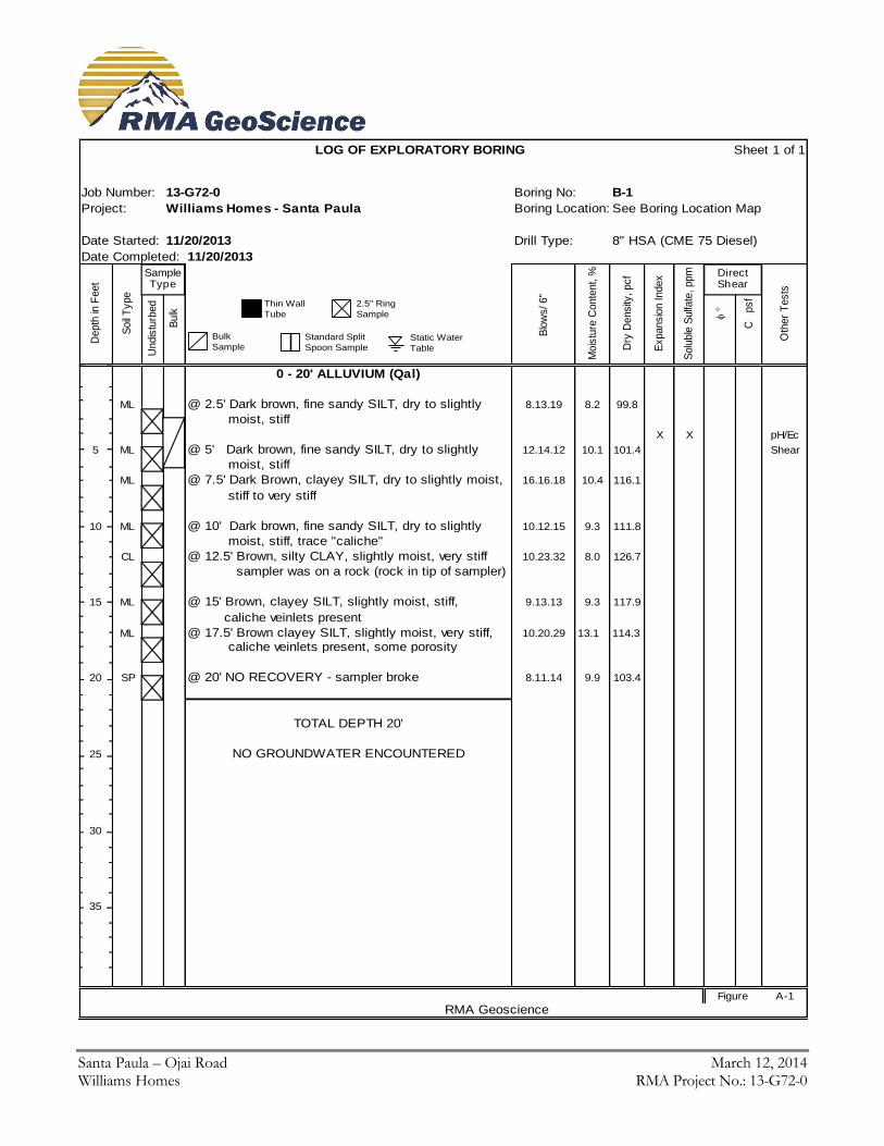
LOG OF EXPLORATORY BORING Sheet 1 of 1
13-G72-0 Boring No: B-1
Williams Homes - Santa Paula Boring Location: See Boring Location Map
Date Started: 11/20/2013 Drill Type: 8" HSA (CME 75 Diesel)
Date Completed: 11/20/2013
Depth
in F
eet
Soil
Type
U
ndis
turb
ed
B
ulk
Blo
ws/ 6"
Mois
ture
Conte
nt, %
Dry
Density
, pcf
Expansio
n Index
Solu
ble
Sulfa
te, ppm
C p
sf
Oth
er
Tests
0 - 20' ALLUVIUM (Qal)
ML @ 2.5' Dark brown, fine sandy SILT, dry to slightly 8.13.19 8.2 99.8
moist, stiff
X X pH/Ec
5 ML @ 5' Dark brown, fine sandy SILT, dry to slightly 12.14.12 10.1 101.4 Shear
moist, stiff
ML @ 7.5' Dark Brown, clayey SILT, dry to slightly moist, 16.16.18 10.4 116.1
stiff to very stiff
10 ML @ 10' Dark brown, fine sandy SILT, dry to slightly 10.12.15 9.3 111.8
moist, stiff, trace "caliche"
CL @ 12.5' Brown, silty CLAY, slightly moist, very stiff 10.23.32 8.0 126.7
sampler was on a rock (rock in tip of sampler)
15 ML @ 15' Brown, clayey SILT, slightly moist, stiff, 9.13.13 9.3 117.9
caliche veinlets present
ML @ 17.5' Brown clayey SILT, slightly moist, very stiff, 10.20.29 13.1 114.3
caliche veinlets present, some porosity
20 SP @ 20' NO RECOVERY - sampler broke 8.11.14 9.9 103.4
TOTAL DEPTH 20'
25 NO GROUNDWATER ENCOUNTERED
30
35
Figure A-1
RMA Geoscience
Job Number:
Project:
DirectShear
Sample Type
SOIL DESCRIPTION
Thin Wall
Tube
2.5" Ring
Sample
Bulk
SampleStandard Split
Spoon SampleStatic Water
Table
Santa Paula – Ojai Road March 12, 2014 Williams Homes RMA Project No.: 13-G72-0
LOG OF EXPLORATORY BORING Sheet 1 of 1
13-G72-0 Boring No: B-2
Williams Homes - Santa Paula Boring Location: See Boring Location Map
Date Started: 11/20/2013 Drill Type: 8" HSA (CME 75 Diesel)
Date Completed: 11/20/2013
Depth
in F
eet
Soil
Type
U
ndis
turb
ed
B
ulk
Blo
ws/ 6"
Mois
ture
Conte
nt, %
Dry
Density
, pcf
Expansio
n Index
Solu
ble
Sulfa
te, ppm
C p
sf
Oth
er
Tests
0 - 33' ALLUVIUM (Qal)
ML @ 3' Dark brown, clayey SILT, slightly moist, stiff 11.15.15 11.2 99.4
5
ML @ 6' Brown, clayey SILT, dry to slight moist, very 11.21.31 9.9 103.4 Consol
stiff, caliche veinlets present, pinhole porosity
ML @ 9' Brown, clayey SILT, slight moist, very stiff 12.19.29 9.2 101.8
10 caliche veinlets present, pinhole porosity
SP @ 14' NO RECOVERY - Refusal (Too rocky) 32.50 for 6"
15
SP @ 18' NO RECOVERY - Refusal (Rock in sampler) 50 for 5"
20 ML @ 20' Brown, clayey SILT, slightly moist, very stiff 16.32.50 for 4" 11.9 115.3
caliche veinlets present
ML @ 22' Mottled, pale and dark brown clayey SILT, dry to 25.38.50 for 4" 8.2 106.2
slightly moist, hard (hard dark brown layer in one ring)
25
ML @ 27' In first 4 rings - rounded cobbles. Toward top of 36.50 for 4" 2.9 106.0
sampler - brown, clayey SILT, slightly moist, very stiff
30
SP @ 33' REFUSAL (Too rocky)
35
TOTAL DEPTH 33'
NO GROUNDWATER ENCOUNTERED
Figure A-2
RMA Geoscience
Job Number:
Project:
DirectShear
Sample Type
SOIL DESCRIPTION
Thin Wall
Tube
2.5" Ring
Sample
Bulk
SampleStandard Split
Spoon SampleStatic Water
Table
Santa Paula – Ojai Road March 12, 2014 Williams Homes RMA Project No.: 13-G72-0
LOG OF EXPLORATORY BORING Sheet 1 of 1
13-G72-0 Boring No: B-3
Williams Homes - Santa Paula Boring Location: See Boring Location Map
Date Started: 11/20/2013 Drill Type: 8" HSA (CME 75 Diesel)
Date Completed: 11/20/2013
Depth
in F
eet
Soil
Type
U
ndis
turb
ed
B
ulk
Blo
ws/ 6"
Mois
ture
Conte
nt, %
Dry
Density
, pcf
Expansio
n Index
Solu
ble
Sulfa
te, ppm
C p
sf
Oth
er
Tests
0 - 30' ALLUVIUM (Qal)
ML @ 1' Dark brown, clayey SILT, dry to slightly moist 10.12.14 9.7 92.6
stiff
ML @ 3' Dark brown, clayey SILT, some small pebbles 28.50 for 6" 8.9 104.1
slightly moist, stiff (sampler was on a rock)
5
ML @ 7' Brown, sandy SILT, slightly moist to moist, 50 for 6" 6.4 96.8
stiff (sampler was on a rock)
10
ML @ 12' Dark brown, clayey SILT, slightly moist, very stiff 13.27.37 9.6 118.1 Consol
caliche veinlets present, pinhole porosity
15
ML @ 16' Med.brown, clayey SILT, slightly moist, very stiff 13.19.20 9.1 104.2
caliche veinlets present, pinhole porosity, rootlets
20
ML @ 21' Med.brown, clayey SILT, slightly moist, very stiff, 9.30.50 for 5" 8.1 104.1
rocky, rare caliche veinlets present, less porosity
25
ML/ @ 28' First 6 rings - clayey SILT w/ caliche veinlets, 28.50 for 5" 8.4 115.2
BR next rings - brown, sandy SILTSTONE, dry, dense
30 BR @ 30' BEDROCK - Brown, sandy SILTSTONE, dry to 24.50 for 3" 4.4 110.7
slightly moist, very dense
TOTAL DEPTH 30'
35 NO GROUNDWATER ENCOUNTERED
Figure A-3
RMA Geoscience
Job Number:
Project:
DirectShear
Sample Type
SOIL DESCRIPTION
Thin Wall
Tube
2.5" Ring
Sample
Bulk
SampleStandard Split
Spoon SampleStatic Water
Table
Santa Paula – Ojai Road March 12, 2014 Williams Homes RMA Project No.: 13-G72-0
LOG OF EXPLORATORY BORING Sheet 1 of 1
13-G72-0 Boring No: B-4
Williams Homes - Santa Paula Boring Location: See Boring Location Map
Date Started: 11/20/2013 Drill Type: 8" HSA (CME 75 Diesel)
Date Completed: 11/20/2013
Depth
in F
eet
Soil
Type
U
ndis
turb
ed
B
ulk
Blo
ws/ 6"
Mois
ture
Conte
nt, %
Dry
Density
, pcf
Expansio
n Index
Solu
ble
Sulfa
te, ppm
C p
sf
Oth
er
Tests
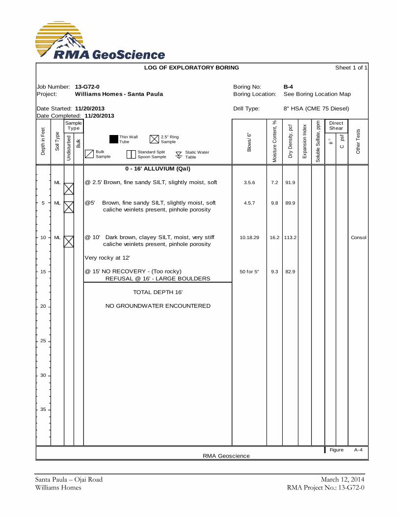
0 - 16' ALLUVIUM (Qal)
ML @ 2.5' Brown, fine sandy SILT, slightly moist, soft 3.5.6 7.2 91.9
5 ML @5' Brown, fine sandy SILT, slightly moist, soft 4.5.7 9.8 89.9
caliche veinlets present, pinhole porosity
10 ML @ 10' Dark brown, clayey SILT, moist, very stiff 10.18.29 16.2 113.2 Consol
caliche veinlets present, pinhole porosity
Very rocky at 12'
15 @ 15' NO RECOVERY - (Too rocky) 50 for 5" 9.3 82.9
REFUSAL @ 16' - LARGE BOULDERS
TOTAL DEPTH 16'
20 NO GROUNDWATER ENCOUNTERED
25
30
35
Figure A-4
RMA Geoscience
Job Number:
Project:
DirectShear
Sample Type
SOIL DESCRIPTION
Thin Wall
Tube
2.5" Ring
Sample
Bulk
SampleStandard Split
Spoon SampleStatic Water
Table
Santa Paula – Ojai Road March 12, 2014 Williams Homes RMA Project No.: 13-G72-0
LOG OF EXPLORATORY BORING Sheet 1 of 1
13-G72-0 Boring No: B-4A
Williams Homes - Santa Paula Boring Location: See Boring Location Map
Date Started: 11/20/2013 Drill Type: 8" HSA (CME 75 Diesel)
Date Completed: 11/20/2013
Depth
in F
eet
Soil
Type
U
ndis
turb
ed
B
ulk
Blo
ws/ 6"
Mois
ture
Conte
nt, %
Dry
Density
, pcf
Expansio
n Index
Solu
ble
Sulfa
te, ppm
C p
sf
Oth
er
Tests
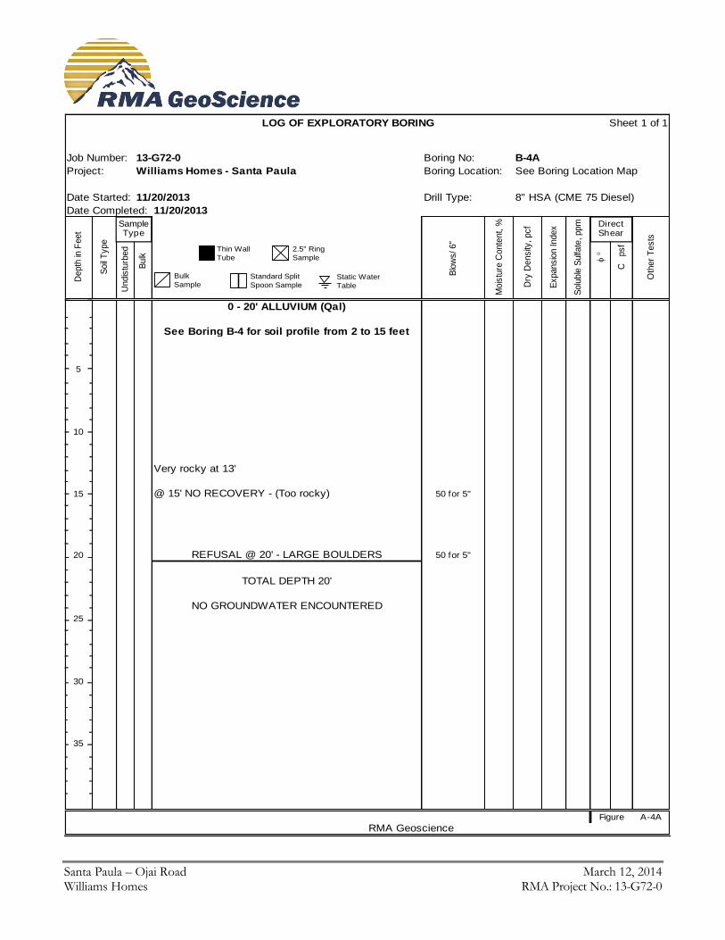
0 - 20' ALLUVIUM (Qal)
See Boring B-4 for soil profile from 2 to 15 feet
5
10
Very rocky at 13'
15 @ 15' NO RECOVERY - (Too rocky) 50 for 5"
20 REFUSAL @ 20' - LARGE BOULDERS 50 for 5"
TOTAL DEPTH 20'
NO GROUNDWATER ENCOUNTERED
25
30
35
Figure A-4A
RMA Geoscience
Job Number:
Project:
DirectShear
Sample Type
SOIL DESCRIPTION
Thin Wall
Tube
2.5" Ring
Sample
Bulk
SampleStandard Split
Spoon SampleStatic Water
Table
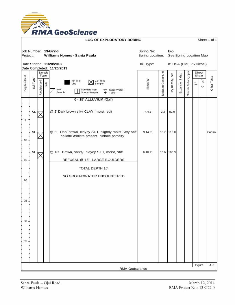
Santa Paula – Ojai Road March 12, 2014 Williams Homes RMA Project No.: 13-G72-0
LOG OF EXPLORATORY BORING Sheet 1 of 1
13-G72-0 Boring No: B-5
Williams Homes - Santa Paula Boring Location: See Boring Location Map
Date Started: 11/20/2013 Drill Type: 8" HSA (CME 75 Diesel)
Date Completed: 11/20/2013
Depth
in F
eet
Soil
Type
U
ndis
turb
ed
B
ulk
Blo
ws/ 6"
Mois
ture
Conte
nt, %
Dry
Density
, pcf
Expansio
n Index
Solu
ble
Sulfa
te, ppm
C p
sf
Oth
er
Tests
0 - 15' ALLUVIUM (Qal)
CL @ 3' Dark brown silty CLAY, moist, soft 4.4.5 9.3 82.9
5
ML @ 8' Dark brown, clayey SILT, slightly moist, very stiff 9.14.21 13.7 115.0 Consol
caliche veinlets present, pinhole porosity
10
ML @ 13' Brown, sandy, clayey SILT, moist, stiff 6.10.21 13.6 108.3
15 REFUSAL @ 15' - LARGE BOULDERS
TOTAL DEPTH 15'
NO GROUNDWATER ENCOUNTERED
20
25
30
35
Figure A-5
RMA Geoscience
Job Number:
Project:
DirectShear
Sample Type
SOIL DESCRIPTION
Thin Wall
Tube
2.5" Ring
Sample
Bulk
SampleStandard Split
Spoon SampleStatic Water
Table

Santa Paula – Ojai Road March 12, 2014 Williams Homes RMA Project No.: 13-G72-0
LOG OF EXPLORATORY BORING Sheet 1 of 1
13-G72-0 Boring No: B-6
Williams Homes - Santa Paula Boring Location: See Boring Location Map
Date Started: 11/20/2013 Drill Type: 8" HSA (CME 75 Diesel)
Date Completed: 11/20/2013
Depth
in F
eet
Soil
Type
U
ndis
turb
ed
B
ulk
Blo
ws/ 6"
Mois
ture
Conte
nt, %
Dry
Density
, pcf
Expansio
n Index
Solu
ble
Sulfa
te, ppm
C p
sf
Oth
er
Tests
0 - 5' ALLUVIUM (Qal)
ML @ 4' Brown, fine clayey SILT, dry to slightly moist, 4.7.21 7.5 86.2
5 soft (rocks in the bottom of sampler)REFUSAL @ 5' - LARGE COBBLES/ BOULDERS
TOTAL DEPTH 5'
10 NO GROUNDWATER ENCOUNTERED
15
20
25
30
35
Figure A-6
RMA Geoscience
Job Number:
Project:
DirectShear
Sample Type
SOIL DESCRIPTION
Thin Wall
Tube
2.5" Ring
Sample
Bulk
SampleStandard Split
Spoon SampleStatic Water
Table
Santa Paula – Ojai Road March 12, 2014 Williams Homes RMA Project No.: 13-G72-0
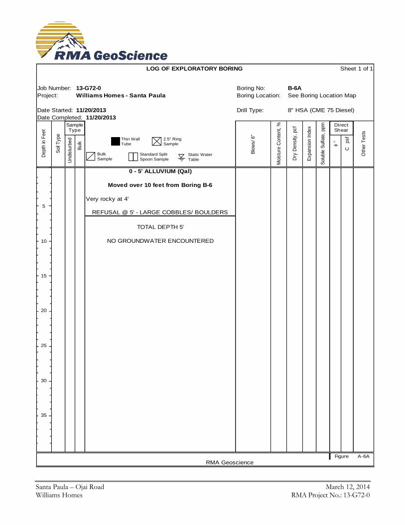
LOG OF EXPLORATORY BORING Sheet 1 of 1
13-G72-0 Boring No: B-6A
Williams Homes - Santa Paula Boring Location: See Boring Location Map
Date Started: 11/20/2013 Drill Type: 8" HSA (CME 75 Diesel)
Date Completed: 11/20/2013
Depth
in F
eet
Soil
Type
U
ndis
turb
ed
B
ulk
Blo
ws/ 6"
Mois
ture
Conte
nt, %
Dry
Density
, pcf
Expansio
n Index
Solu
ble
Sulfa
te, ppm
C p
sf
Oth
er
Tests
0 - 5' ALLUVIUM (Qal)
Moved over 10 feet from Boring B-6
Very rocky at 4'
5
REFUSAL @ 5' - LARGE COBBLES/ BOULDERS
TOTAL DEPTH 5'
10 NO GROUNDWATER ENCOUNTERED
15
20
25
30
35
Figure A-6A
RMA Geoscience
Job Number:
Project:
DirectShear
Sample Type
SOIL DESCRIPTION
Thin Wall
Tube
2.5" Ring
Sample
Bulk
SampleStandard Split
Spoon SampleStatic Water
Table
Santa Paula – Ojai Road March 12, 2014 Williams Homes RMA Project No.: 13-G72-0
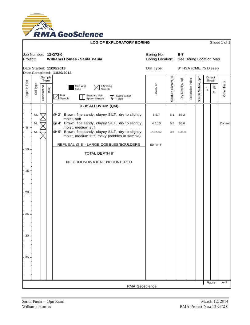
LOG OF EXPLORATORY BORING Sheet 1 of 1
13-G72-0 Boring No: B-7
Williams Homes - Santa Paula Boring Location: See Boring Location Map
Date Started: 11/20/2013 Drill Type: 8" HSA (CME 75 Diesel)
Date Completed: 11/20/2013
Depth
in F
eet
Soil
Type
U
ndis
turb
ed
B
ulk
Blo
ws/ 6"
Mois
ture
Conte
nt, %
Dry
Density
, pcf
Expansio
n Index
Solu
ble
Sulfa
te, ppm
C p
sf
Oth
er
Tests
0 - 8' ALLUVIUM (Qal)
ML @ 2' Brown, fine sandy, clayey SILT, dry to slightly 5.5.7 5.1 86.2
moist, soft
ML @ 4' Brown, fine sandy, clayey SILT, dry to slightly 4.6.10 6.5 95.6 Consol
5 moist, medium stiff
ML @ 6' Brown, fine sandy, clayey SILT, dry to slightly 7.37.42 3.6 108.4
moist, medium stiff, rocky (cobbles in sample)
REFUSAL @ 8' - LARGE COBBLES/BOULDERS 50 for 4"
10
TOTAL DEPTH 8'
NO GROUNDWATER ENCOUNTERED
15
20
25
30
35
Figure A-7
RMA Geoscience
Job Number:
Project:
DirectShear
Sample Type
SOIL DESCRIPTION
Thin Wall
Tube
2.5" Ring
Sample
Bulk
SampleStandard Split
Spoon SampleStatic Water
Table
Santa Paula – Ojai Road March 12, 2014 Williams Homes RMA Project No.: 13-G72-0
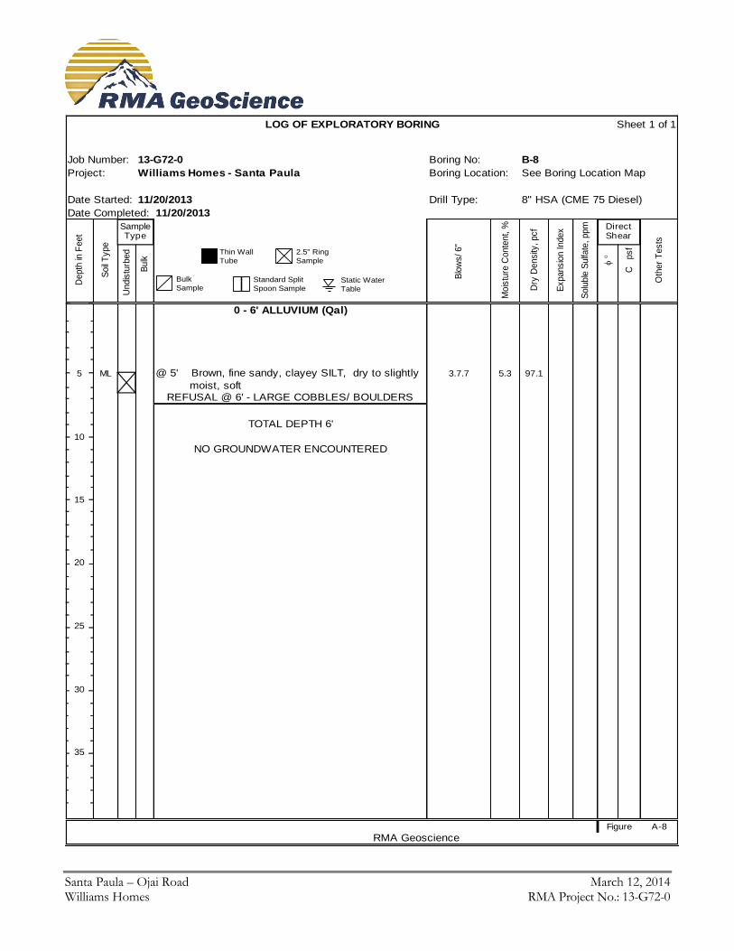
LOG OF EXPLORATORY BORING Sheet 1 of 1
13-G72-0 Boring No: B-8
Williams Homes - Santa Paula Boring Location: See Boring Location Map
Date Started: 11/20/2013 Drill Type: 8" HSA (CME 75 Diesel)
Date Completed: 11/20/2013
Depth
in F
eet
Soil
Type
U
ndis
turb
ed
B
ulk
Blo
ws/ 6"
Mois
ture
Conte
nt, %
Dry
Density
, pcf
Expansio
n Index
Solu
ble
Sulfa
te, ppm
C p
sf
Oth
er
Tests
0 - 6' ALLUVIUM (Qal)
5 ML @ 5' Brown, fine sandy, clayey SILT, dry to slightly 3.7.7 5.3 97.1
moist, soft
REFUSAL @ 6' - LARGE COBBLES/ BOULDERS
TOTAL DEPTH 6'
10
NO GROUNDWATER ENCOUNTERED
15
20
25
30
35
Figure A-8
RMA Geoscience
Job Number:
Project:
DirectShear
Sample Type
SOIL DESCRIPTION
Thin Wall
Tube
2.5" Ring
Sample
Bulk
SampleStandard Split
Spoon SampleStatic Water
Table
Santa Paula – Ojai Road March 12, 2014 Williams Homes RMA Project No.: 13-G72-0
APPENDIX B
LABORATORY TESTS
Santa Paula – Ojai Road March 12, 2014 Williams Homes RMA Project No.: 13-G72-0 Page B - 1
Appendix B
Laboratory Tests
B-1.00 Laboratory Tests B-1.01 Maximum Density
Maximum density - optimum moisture relationships for the major soil types encountered during the field exploration were performed in the laboratory using the standard procedures of ASTM D1557.
B-1.02 Consolidation (One-Dimensional) One-dimensional consolidation tests were performed using the standard test method of ASTM D2435. The rate of consolidation of the tested sample was not determined and the applied test pressure is indicated on the summary of the test results. To simulate possible adverse field conditions, moisture was added to an axial load of 1250 pounds per square foot. B-1.03 Direct Shear Direct shear tests were performed on remolded ring samples of the alluvial soils encountered in the test holes using the standard test method of ASTM D3080 (consolidated and drained). Remolded samples were tested at 90 percent relative compaction.Shear tests were performed on a direct shear machine of the strain-controlled type. To simulate possible adverse field conditions, the samples were saturated prior to shearing. Samples were sheared at varying normal loads and the results plotted to establish the angle of the internal friction and cohesion of the tested samples. B-1.04 Expansion Tests
Expansion index tests were performed on representative samples of the major soil types encountered by the test methods outlined in ASTM D4829. B-1.05 Soluble Sulfates
Test was performed on representative sample encountered during the investigation using the HACH DR3 (Calcium Phosphate Extractable) procedures. B-1.06 Soil Reactivity (pH) and Electrical Conductivity (Ec)
Representative soil sample was tested for soil reactivity (pH) and electrical conductivity (Ec) using California Test Method S3.0 and S5.0. The pH measurement determines the degree of acidity or alkalinity in the soils. The Ec is a measure of the electrical resistivity and is expressed as the reciprocal of the resistivity. B-1.07 Moisture Determination
Moisture content of the soil samples was performed in accordance to standard method for determination of water content of soil by drying oven, ASTM D2216. The mass of material remaining after oven drying is used as the mass of the solid particles. B-1.08 Test Results
Test results for all laboratory tests performed on the subject project are presented in this appendix. For a sample-by-sample description, see the Boring Log(s) presented in Appendix A.
Santa Paula – Ojai Road March 12, 2014 Williams Homes RMA Project No.: 13-G72-0 Page B - 2
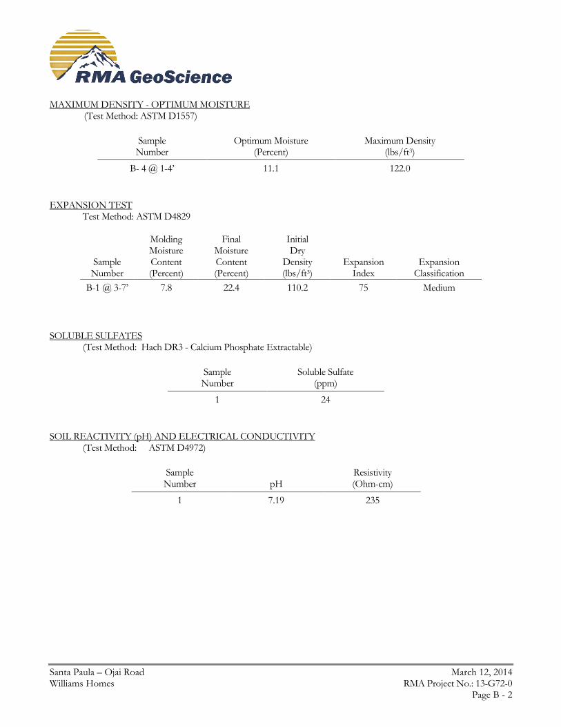
MAXIMUM DENSITY - OPTIMUM MOISTURE (Test Method: ASTM D1557)
Sample Number
Optimum Moisture (Percent)
Maximum Density (lbs/ft3)
B- 4 @ 1-4’ 11.1 122.0
EXPANSION TEST Test Method: ASTM D4829
Sample Number
Molding Moisture Content (Percent)
Final Moisture Content (Percent)
Initial Dry
Density (lbs/ft3)
Expansion Index
Expansion Classification
B-1 @ 3-7’ 7.8 22.4 110.2 75 Medium
SOLUBLE SULFATES (Test Method: Hach DR3 - Calcium Phosphate Extractable)
Sample Number
Soluble Sulfate (ppm)
1 24
SOIL REACTIVITY (pH) AND ELECTRICAL CONDUCTIVITY (Test Method: ASTM D4972)
Sample Number
pH
Resistivity (Ohm-cm)
1 7.19 235
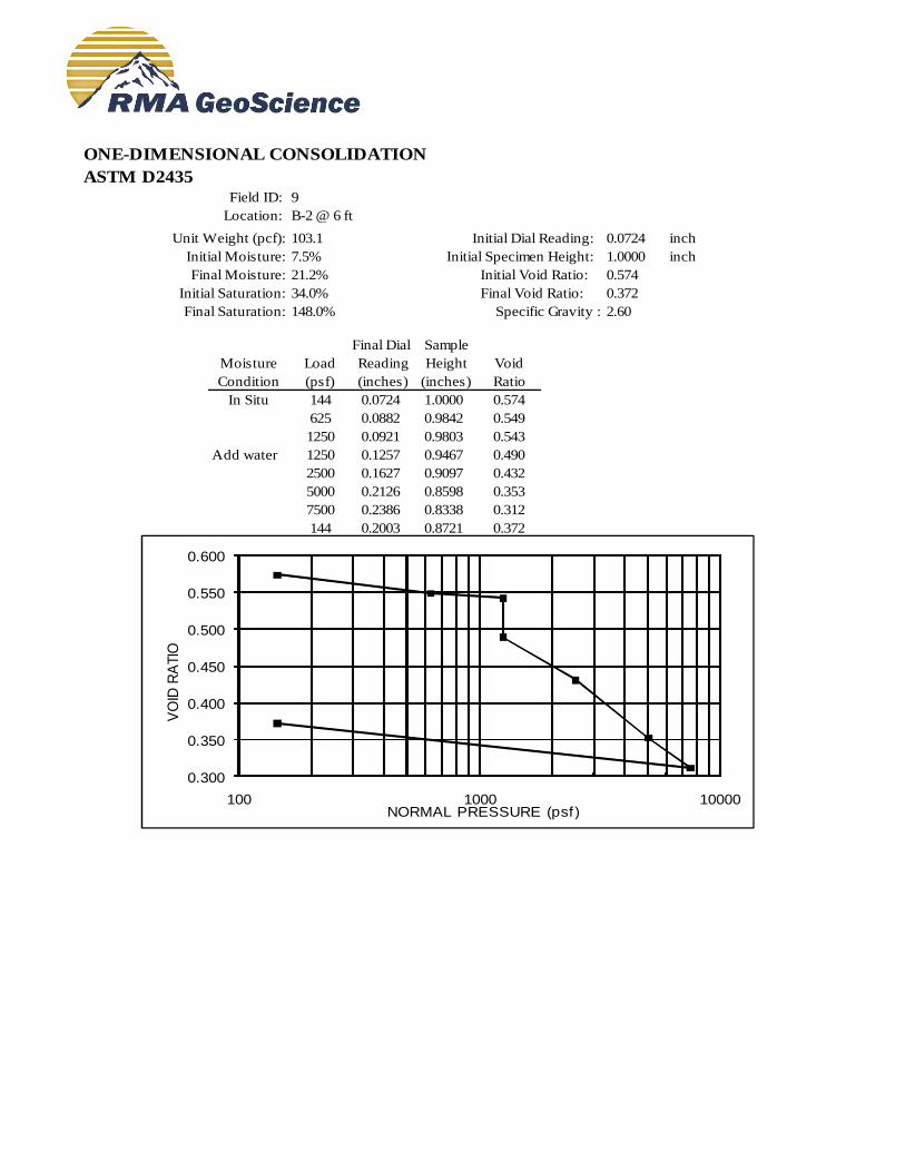
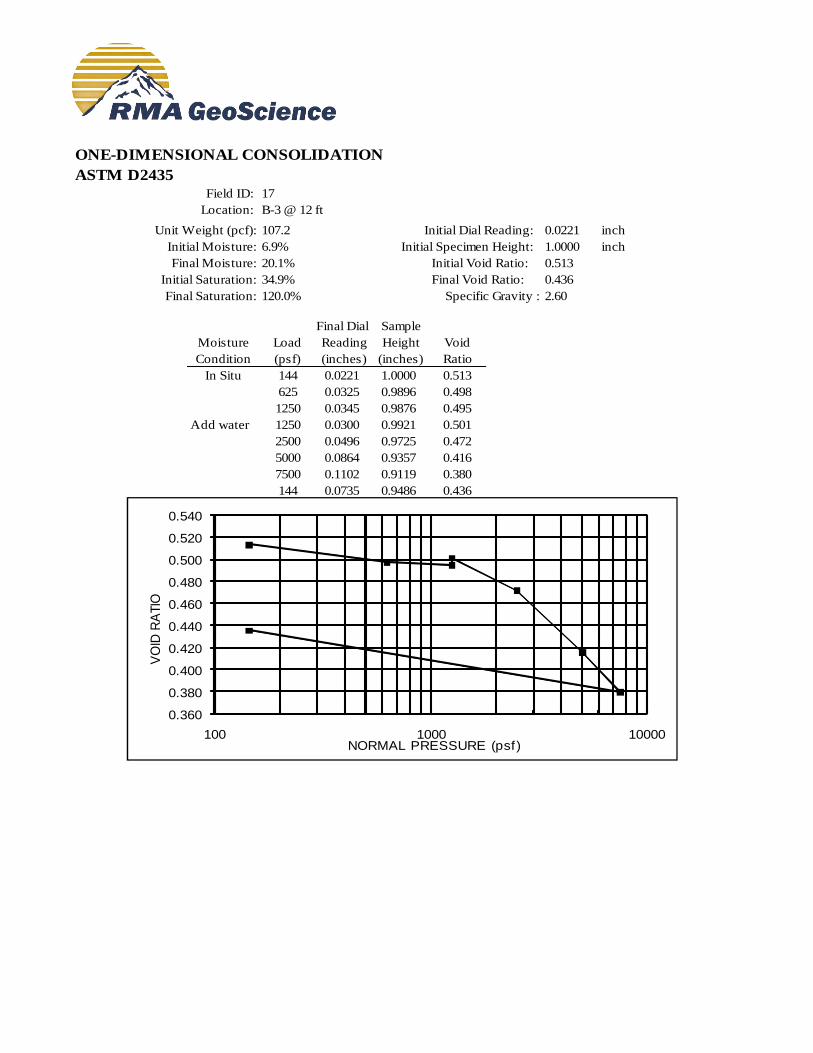
ONE-DIMENSIONAL CONSOLIDATION
ASTM D2435
Field ID: 9
Location: B-2 @ 6 ft
Unit Weight (pcf): 103.1 Initial Dial Reading: 0.0724 inch
Initial Moisture: 7.5% Initial Specimen Height: 1.0000 inch
Final Moisture: 21.2% Initial Void Ratio: 0.574
Initial Saturation: 34.0% Final Void Ratio: 0.372
Final Saturation: 148.0% Specific Gravity : 2.60
Final Dial Sample
Moisture Load Reading Height Void
Condition (psf) (inches) (inches) Ratio
In Situ 144 0.0724 1.0000 0.574
625 0.0882 0.9842 0.549
1250 0.0921 0.9803 0.543
Add water 1250 0.1257 0.9467 0.490
2500 0.1627 0.9097 0.432
5000 0.2126 0.8598 0.353
7500 0.2386 0.8338 0.312
144 0.2003 0.8721 0.372
0.300
0.350
0.400
0.450
0.500
0.550
0.600
100 1000 10000
VO
ID R
ATIO
NORMAL PRESSURE (psf)
ONE-DIMENSIONAL CONSOLIDATION
ASTM D2435
Field ID: 17
Location: B-3 @ 12 ft
Unit Weight (pcf): 107.2 Initial Dial Reading: 0.0221 inch
Initial Moisture: 6.9% Initial Specimen Height: 1.0000 inch
Final Moisture: 20.1% Initial Void Ratio: 0.513
Initial Saturation: 34.9% Final Void Ratio: 0.436
Final Saturation: 120.0% Specific Gravity : 2.60
Final Dial Sample
Moisture Load Reading Height Void
Condition (psf) (inches) (inches) Ratio
In Situ 144 0.0221 1.0000 0.513
625 0.0325 0.9896 0.498
1250 0.0345 0.9876 0.495
Add water 1250 0.0300 0.9921 0.501
2500 0.0496 0.9725 0.472
5000 0.0864 0.9357 0.416
7500 0.1102 0.9119 0.380
144 0.0735 0.9486 0.436
0.360
0.380
0.400
0.420
0.440
0.460
0.480
0.500
0.520
0.540
100 1000 10000
VO
ID R
ATIO
NORMAL PRESSURE (psf)
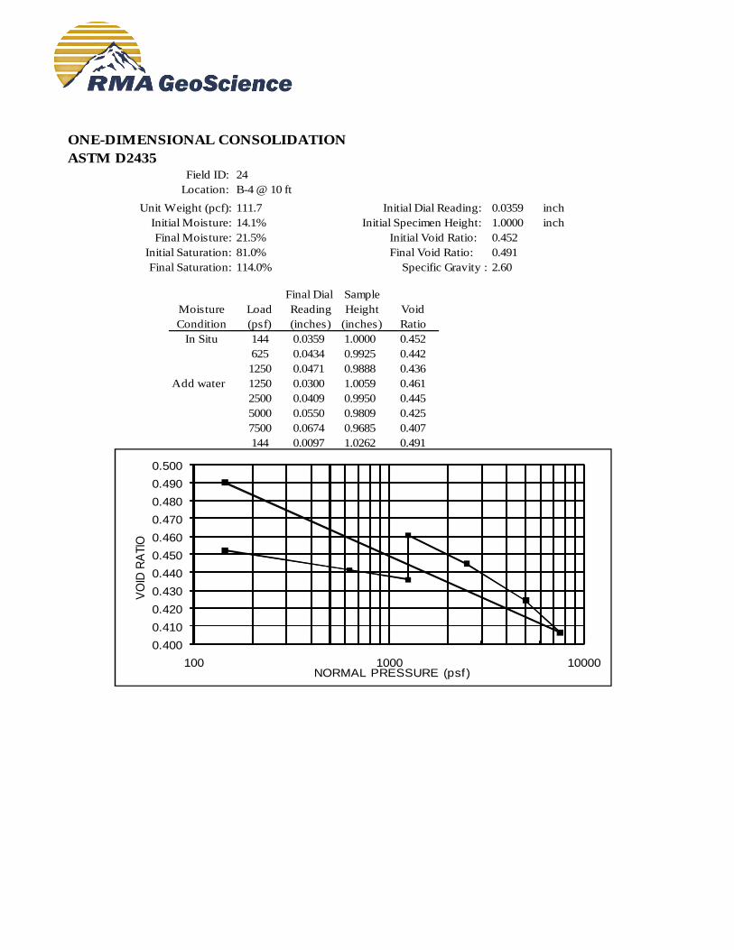
ONE-DIMENSIONAL CONSOLIDATION
ASTM D2435
Field ID: 24
Location: B-4 @ 10 ft
Unit Weight (pcf): 111.7 Initial Dial Reading: 0.0359 inch
Initial Moisture: 14.1% Initial Specimen Height: 1.0000 inch
Final Moisture: 21.5% Initial Void Ratio: 0.452
Initial Saturation: 81.0% Final Void Ratio: 0.491
Final Saturation: 114.0% Specific Gravity : 2.60
Final Dial Sample
Moisture Load Reading Height Void
Condition (psf) (inches) (inches) Ratio
In Situ 144 0.0359 1.0000 0.452
625 0.0434 0.9925 0.442
1250 0.0471 0.9888 0.436
Add water 1250 0.0300 1.0059 0.461
2500 0.0409 0.9950 0.445
5000 0.0550 0.9809 0.425
7500 0.0674 0.9685 0.407
144 0.0097 1.0262 0.491
0.400
0.410
0.420
0.430
0.440
0.450
0.460
0.470
0.480
0.490
0.500
100 1000 10000
VO
ID R
ATIO
NORMAL PRESSURE (psf)
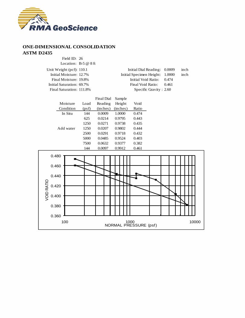
ONE-DIMENSIONAL CONSOLIDATION
ASTM D2435
Field ID: 26
Location: B-5 @ 8 ft
Unit Weight (pcf): 110.1 Initial Dial Reading: 0.0009 inch
Initial Moisture: 12.7% Initial Specimen Height: 1.0000 inch
Final Moisture: 19.8% Initial Void Ratio: 0.474
Initial Saturation: 69.7% Final Void Ratio: 0.461
Final Saturation: 111.8% Specific Gravity : 2.60
Final Dial Sample
Moisture Load Reading Height Void
Condition (psf) (inches) (inches) Ratio
In Situ 144 0.0009 1.0000 0.474
625 0.0214 0.9795 0.443
1250 0.0271 0.9738 0.435
Add water 1250 0.0207 0.9802 0.444
2500 0.0291 0.9718 0.432
5000 0.0485 0.9524 0.403
7500 0.0632 0.9377 0.382
144 0.0097 0.9912 0.461
0.360
0.380
0.400
0.420
0.440
0.460
0.480
100 1000 10000
VO
ID R
ATIO
NORMAL PRESSURE (psf)

ONE-DIMENSIONAL CONSOLIDATION
ASTM D2435
Field ID: 30
Location: B-7 @ 4 ft
Unit Weight (pcf): 94.1 Initial Dial Reading: 0.0754 inch
Initial Moisture: 5.5% Initial Specimen Height: 1.0000 inch
Final Moisture: 24.9% Initial Void Ratio: 0.724
Initial Saturation: 19.7% Final Void Ratio: 0.548
Final Saturation: 118.1% Specific Gravity : 2.60
Final Dial Sample
Moisture Load Reading Height Void
Condition (psf) (inches) (inches) Ratio
In Situ 144 0.0754 1.0000 0.724
625 0.0813 0.9941 0.714
1250 0.0862 0.9892 0.706
Add water 1250 0.1069 0.9685 0.670
2500 0.1365 0.9389 0.619
5000 0.1734 0.9020 0.555
7500 0.1944 0.8810 0.519
144 0.1774 0.8980 0.548
0.400
0.450
0.500
0.550
0.600
0.650
0.700
0.750
100 1000 10000
VO
ID R
ATIO
NORMAL PRESSURE (psf)
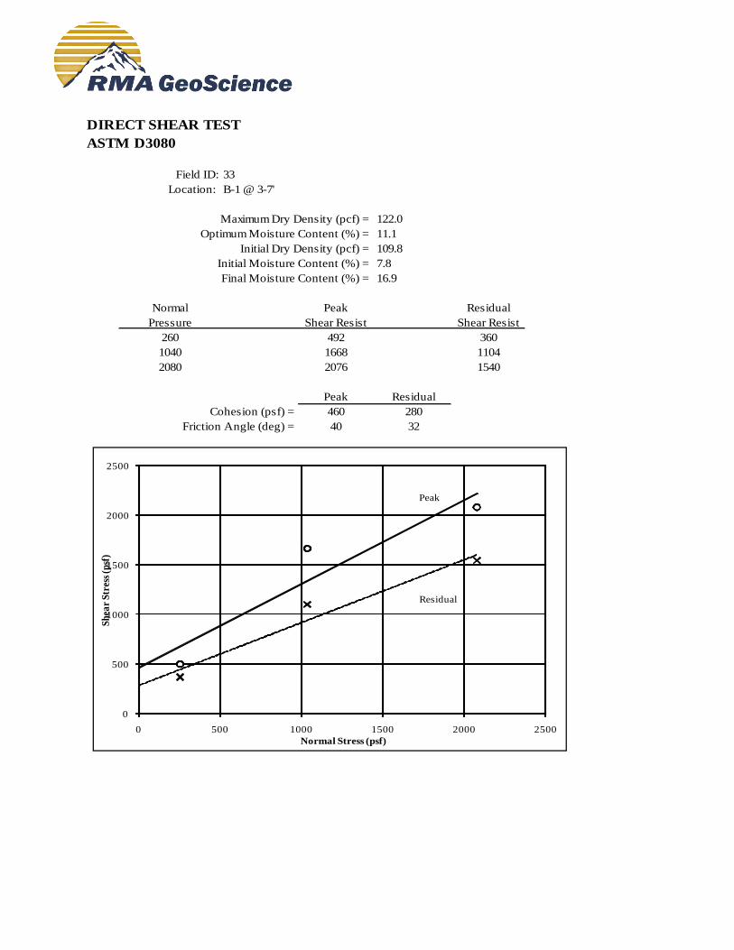
DIRECT SHEAR TEST
ASTM D3080
Field ID: 33
Location: B-1 @ 3-7'
Maximum Dry Density (pcf) = 122.0
Optimum Moisture Content (%) = 11.1
Initial Dry Density (pcf) = 109.8
Initial Moisture Content (%) = 7.8
Final Moisture Content (%) = 16.9
Normal Peak Residual
Pressure Shear Resist Shear Resist
260 492 360
1040 1668 1104
2080 2076 1540
Peak Residual
Cohesion (psf) = 460 280
Friction Angle (deg) = 40 32
Peak
Residual
0
500
1000
1500
2000
2500
0 500 1000 1500 2000 2500
Sh
ear
Str
ess
(psf
)
Normal Stress (psf)

APPENDIX C
GENERAL EARTHWORK AND
GRADING SPECIFICATIONS
General Earthwork and Grading Specifications
C-1.00 General Description
C-1.01 Introduction
These specifications present our general recommendations for earthwork and grading as shown on the approved grading
plans for the subject project. These specifications shall cover all clearing and grubbing, removal of existing structures,
preparation of land to be filled, filling of the land, spreading, compaction and control of the fill, and all subsidiary work
necessary to complete the grading of the filled areas to conform with the lines, grades and slopes as shown on the
approved plans.
The recommendations contained in the geotechnical report of which these general specifications are a part of shall
supersede the provisions contained hereinafter in case of conflict.
C-1.02 Laboratory Standard and Field Test Methods
The laboratory standard used to establish the maximum density and optimum moisture shall be ASTM D 1557.
The insitu density of earth materials (field compaction tests) shall be determined by the sand cone method (ASTM
D1556), direct transmission nuclear method (ASTM D2922) or other test methods as considered appropriate by the
geotechnical consultant.
Relative compaction is defined, for purposes of these specifications, as the ratio of the in-place density to the maximum
density as determined in the previously mentioned laboratory standard.
C-2.00 Clearing
C-2.01 Surface Clearing
All structures marked for removal, timber, logs, trees, brush and other rubbish shall be removed and disposed of off the
site. Any trees to be removed shall be pulled in such a manner so as to remove as much of the root system as possible. C-2.02 Subsurface Removals
A thorough search should be made for possible underground storage tanks and/or septic tanks and cesspools. If found,
tanks should be removed and cesspools pumped dry.
Any concrete irrigation lines shall be crushed in place and all metal underground lines shall be removed from the site.
C-2.03 Backfill of Cavities
All cavities created or exposed during clearing and grubbing operations or by previous use of the site shall be cleared of
deleterious material and backfilled with native soils or other materials approved by the soil engineer. Said backfill shall be
compacted to a minimum of 90% relative compaction.
C-3.00 Original Ground Preparation
C-3.01 Stripping of Vegetation
After the site has been properly cleared, all vegetation and topsoil containing the root systems of former vegetation shall
be stripped from areas to be graded. Materials removed in this stripping process may be used as fill in areas designated by
the soil engineer, provided the vegetation is mixed with a sufficient amount of soil to assure that no appreciable settlement
or other detriment will occur due to decaying of the organic matter. Soil materials containing more than 3% organics shall
not be used as structural fill.
C-3.02 Removals of Non-Engineered Fills
Any non-engineered fills encountered during grading shall be completely removed and the underlying ground shall be
prepared in accordance to the recommendations for original ground preparation contained in this section. After cleansing
of any organic matter the fill material may be used for engineered fill.
C-3.03 Overexcavation of Fill Areas
The existing ground in all areas determined to be satisfactory for the support of fills shall be scarified to a minimum depth
of 6 inches. Scarification shall continue until the soils are broken down and free from lumps or clods and until the
scarified zone is uniform. The moisture content of the scarified zone shall be adjusted to within 2% of optimum
moisture. The scarified zone shall then be uniformly compacted to 90% relative compaction. Where fill material is to be placed on ground with slopes steeper than 5:1 (H:V) the sloping ground shall be benched. The lowermost bench shall be a minimum of 15 feet wide, shall be a minimum of 2 feet deep, and shall expose firm material as determined by the geotechnical consultant. Other benches shall be excavated to firm material as determined by the geotechnical consultant and shall have a minimum width of 4 feet. Existing ground that is determined to be unsatisfactory for the support of fills shall be overexcavated in accordance to the recommendations contained in the geotechnical report of which these general specifications are a part.
C-4.00 Fill Materials
C-4.01 General Materials for the fill shall be free from vegetable matter and other deleterious substances, shall not contain rocks or lumps of a greater dimension than is recommended by the geotechnical consultant, and shall be approved by the geotechnical consultant. Soils of poor gradation, expansion, or strength properties shall be placed in areas designated by the geotechnical consultant or shall be mixed with other soils providing satisfactory fill material. C-4.02 Oversize Material Oversize material, rock or other irreducible material with a maximum dimension greater than 12 inches, shall not be placed in fills, unless the location, materials, and disposal methods are specifically approved by the geotechnical consultant. Oversize material shall be placed in such a manner that nesting of oversize material does not occur and in such a manner that the oversize material is completely surrounded by fill material compacted to a minimum of 90% relative compaction. Oversize material shall not be placed within 10 feet of finished grade without the approval of the geotechnical consultant. C-4.03 Import Material imported to the site shall conform to the requirements of Section 4.01 of these specifications. Potential import material shall be approved by the geotechnical consultant prior to importation to the subject site.
C-5.00 Placing and Spreading of Fill
C-5.01 Fill Lifts The selected fill material shall be placed in nearly horizontal layers which when compacted will not exceed approximately 6 inches in thickness. Thicker lifts may be placed if testing indicates the compaction procedures are such that the required compaction is being achieved and the geotechnical consultant approves their use. Each layer shall be spread evenly and shall be thoroughly blade mixed during the spreading to insure uniformity of material in each layer. C-5.02 Fill Moisture When the moisture content of the fill material is below that recommended by the soils engineer, water shall then be added until he moisture content is as specified to assure thorough bonding during the compacting process. When the moisture content of the fill material is above that recommended by the soils engineer, the fill material shall be aerated by blading or other satisfactory methods until the moisture content is as specified. C-5.03 Fill Compaction After each layer has been placed, mixed, and spread evenly, it shall be thoroughly compacted to not less than 90% relative compaction. Compaction shall be by sheepsfoot rollers, multiple-wheel pneumatic tired rollers, or other types approved by the soil engineer. Rolling shall be accomplished while the fill material is at the specified moisture content. Rolling of each layer shall be continuous over its entire area and the roller shall make sufficient trips to insure that the desired density has been obtained. C-5.04 Fill Slopes Fill slopes shall be compacted by means of sheepsfoot rollers or other suitable equipment. Compacting of the slopes may be done progressively in increments of 3 to 4 feet in fill height. At the completion of grading, the slope face shall be compacted to a minimum of 90% relative compaction. This may require track rolling or rolling with a grid roller attached to a tractor mounted side-boom. Slopes may be over filled and cut back in such a manner that the exposed slope faces are compacted to a minimum of 90% relative compaction. The fill operation shall be continued in six inch (6") compacted layers, or as specified above, until the fill has been brought to the finished slopes and grades as shown on the accepted plans. C-5.05 Compaction Testing Field density tests shall be made by the geotechnical consultant of the compaction of each layer of fill. Density tests shall be made at locations selected by the geotechnical consultant. Frequency of field density tests shall be not less than one test for each 2.0 feet of fill height and at least every one thousand cubic yards of fill. Where fill slopes exceed four feet in height their finished faces shall be tested at a frequency of one test for each 1000 square feet of slope face. Where sheepsfoot rollers are used, the soil may be disturbed to a depth of several inches. Density reading shall be taken in the compacted material below the disturbed surface. When these readings indicate that the density of any layer of fill or
portion thereof is below the required density, the particular layer or portion shall be reworked until the required density has been obtained.
C-6.00 Subdrains
C-6.01 Subdrain Material Subdrains shall be constructed of a minimum 4-inch diameter pipe encased in a suitable filter material. The subdrain pipe shall be Schedule 40 Acrylonitrile Butadiene Styrene (ABS) or Schedule 40 Polyvinyl Chloride Plastic (PVC) pipe or approved equivalent. Subdrain pipe shall be installed with perforations down. Filter material shall consist of 3/4" to 1 1/2" clean gravel wrapped in an envelope of filter fabric consisting of Mirafi 140N or approved equivalent. C-6.02 Subdrain Installation Subdrain systems, if required, shall be installed in approved ground to conform the approximate alignment and details shown on the plans or herein. The subdrain locations shall not be changed or modified without the approval of the geotechnical consultant. The geotechnical consultant may recommend and direct changes in the subdrain line, grade or material upon approval by the design civil engineer and the appropriate governmental agencies.
C-7.00 Excavations
C-7.01 General Excavations and cut slopes shall be examined by the geotechnical consultant. If determined necessary by the geotechnical consultant, further excavation or overexcavation and refilling of overexcavated areas shall be performed, and/or remedial grading of cut slopes shall be performed. C-7.02 Fill-Over-Cut Slopes Where fill-over-cut slopes are to be graded the cut portion of the slope shall be made and approved by the geotechnical consultant prior to placement of materials for construction of the fill portion of the slope.
C-8.00 Trench Backfill
C-8.01 General Trench backfill within street right of ways shall be compacted to 90% relative compaction as determined by the ASTM D1557 test method. Backfill may be jetted as a means of initial compaction; however, mechanical compaction will be required to obtain the required percentage of relative compaction. If trenches are jetted, there must be a suitable delay for drainage of excess water before mechanical compaction is applied.
C-9.00 Seasonal Limits
C-9.01 General No fill material shall be placed, spread or rolled while it is frozen or thawing or during unfavorable weather conditions. When the work is interrupted by heavy rain, fill operations shall not be resumed until field tests by the soils engineer indicate that the moisture content and density of the fill are as previously specified.
C-10.00 Supervision
C-10.01 Prior to Grading The site shall be observed by the geotechnical consultant upon completion of clearing and grubbing, prior to the preparation of any original ground for preparation of fill. The supervisor of the grading contractor and the field representative of the geotechnical consultant shall have a meeting and discuss the geotechnical aspects of the earthwork prior to commencement of grading. C-10.02 During Grading
Site preparation of all areas to receive fill shall be tested and approved by the geotechnical consultant prior to the placement of any fill. The geotechnical consultant or his representative shall observe the fill and compaction operations so that he can provide an opinion regarding the conformance of the work to the recommendations

APPENDIX D
REFERENCES
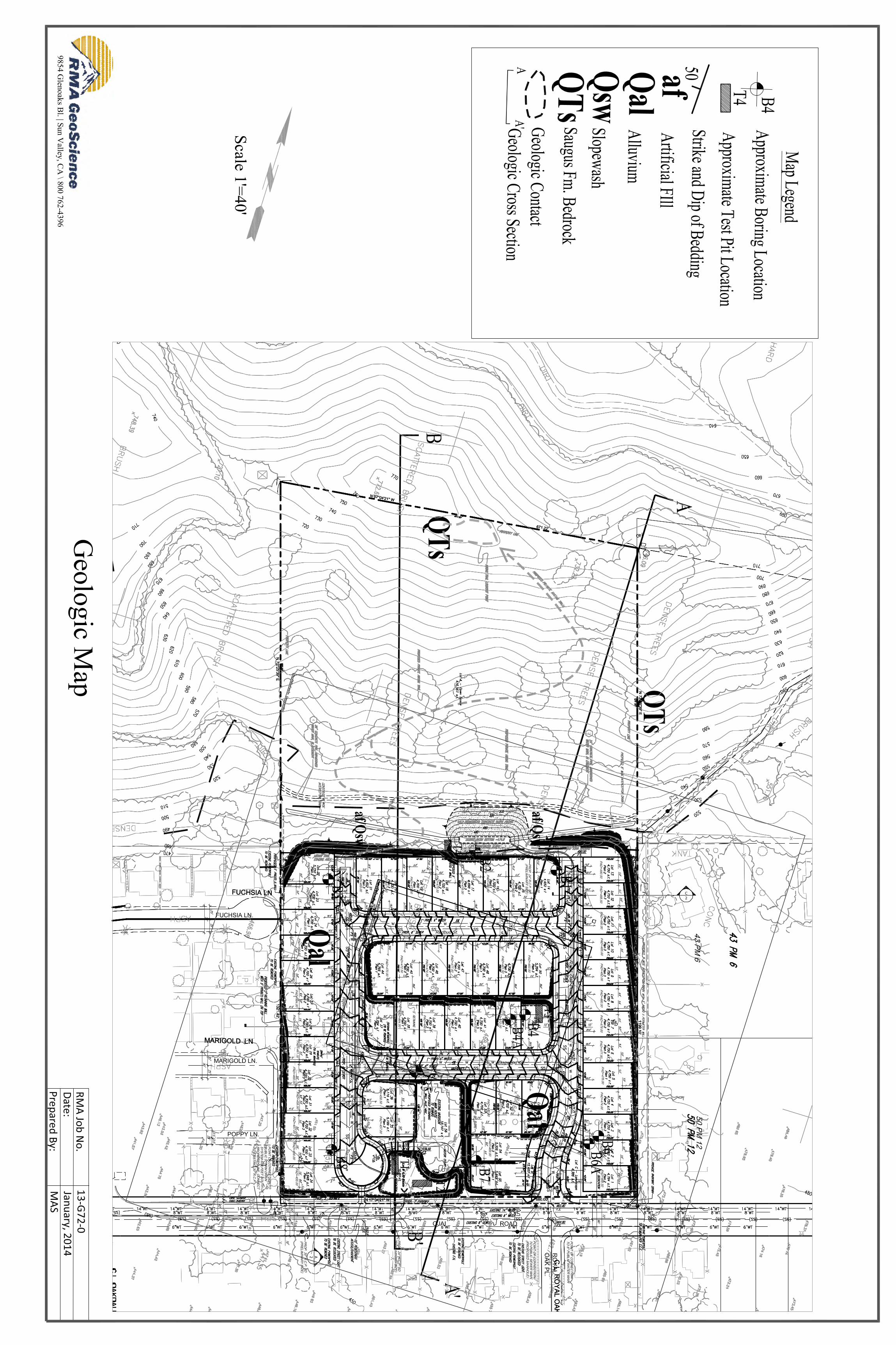
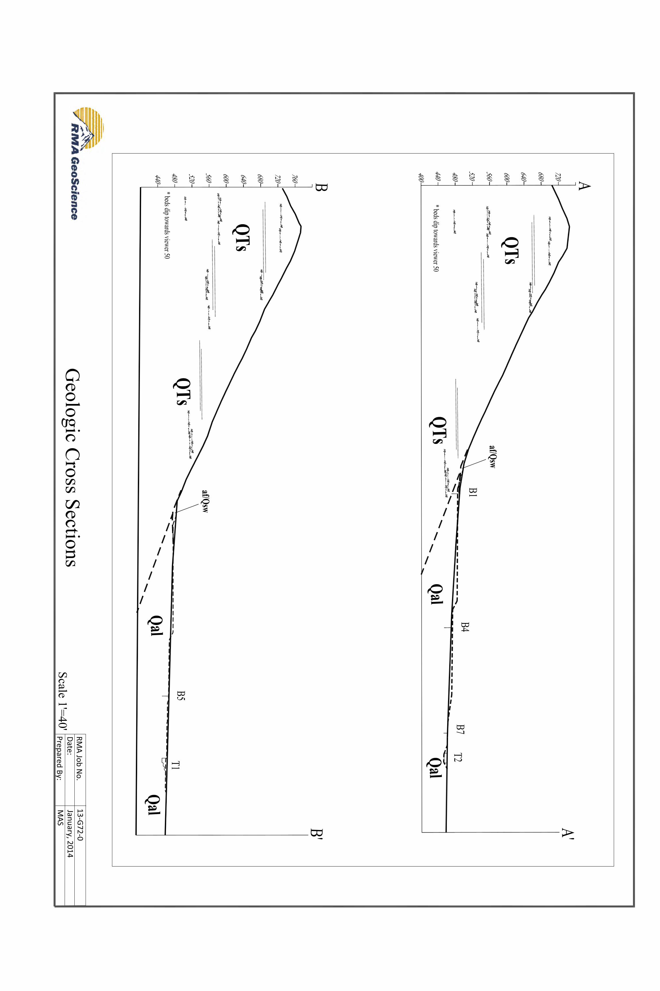
Santa Paula – Ojai Road March 12, 2014 Williams Homes RMA Project No.: 13-G72-0 Page D- 1
REFERENCES
1. California Building Standards Commission, 2013 California Building Code.
2. California Department of Conservation, Division of Mines and Geology, 2008, Guidelines for Evaluating and Mitigating Seismic Hazards in California, Special Publication 117.
3. California Division of Mines and Geology, 2002, Seismic Hazards Zone Report for the Santa Paula 7.5-Minute Quadrangle, Los Angeles County, California, Seismic Hazard Report 061.
4. Cao, Y. and others, 2003, The Revised 2002 California Probabilistic Seismic Hazard Maps, June 2003.
5. Google Earth, Aerial Photographs, 1994-2012
6. Jennings, C.W., and Bryant, W.A, 2010, Fault Activity Map of California, California Geological Survey, Geologic Data Map No. 6.
7. Martin, G.R. and Lew, M., 1999, Recommended Procedures for Implementation of DMG Special Publication 117
8. U.S. Geological Survey, 2011, Java Ground Motion Parameter Calculator, Version 3.1.0, ASCE 10 Standard,
http://geohazards.usgs.gov/designmaps/us/application.php.
![TENTATIVE TRACT MAP NO. 18952 UNINCORPORATED AREA OF ... · quadrangle (United States Geological Survey [USGS] 1967, photorevised 1988) (Figure 1). The project parcels have been severely](https://img.dokumen.tips/doc/110x75/5fcf4d5c1929ef49f019c1ca/tentative-tract-map-no-18952-unincorporated-area-of-quadrangle-united-states.jpg)