Embed Size (px)
Citation preview

Appendix C: Structures Manager including Survey 123 Inspections
ROAD STRUCTURES INSPECTION MANUAL I
Road Structures Inspection Manual
Appendix C: Structures Manager including Survey 123 Inspections Department for Infrastructure and Transport, South Australia
For further information regarding DIT Road Structures Inspection Manual please contact:
The Principal Engineer Structures Technical Services Section Level 5, 77 Grenfell Street Adelaide SA 5000
www.dit.sa.gov.au
RAS Document No: RAMA-ST-PRC-048 Knet Document No: 15769691 Document version: 1.2 (08/09/2020)
Previously, this document was called the Bridge Inspection Manual. First published in 2003 then revised in 2005, 2008, 2019 and 2020.
Disclaimer Every effort has been made to supply complete and accurate information. This document is subject to continual revision and may change. It is the user’s responsibility to check DIT’s website to ensure that the current version is being used.
Copyright
This content is licensed under a Creative Commons Attribution 3.0 Australia Licence
© Government of South Australia (Department for Infrastructure and Transport) 2020
Feedback: Please send your feedback regarding this document to: [email protected]
Appendix C: Structures Manager including Survey 123 Inspections
ROAD STRUCTURES INSPECTION MANUAL II
TABLE OF CONTENTS
1
1
1 STRUCTURES MANAGER 1
Prerequisites 1
2 STRUCTURES MAP 2
2.1 STRUCTURES MAP LAYOUT 3
2.2 MAP AND NAVIGATION TOOLS 3
2.3 USER INTERFACE TOOLS 4
2.4 ATTRIBUTE TABLES 5
2.4.1 Filtering Attribute Tables 6
2.5 MAP INFORMATION 7
2.6 POP-UP STRUCTURE DATA 7
3 AWS (CLOUD) STORAGE 8
3.1 AWS APPLICATION LAYOUT 9
1. Structure/Folder Navigation Panel 9
2. Top Menu 9
3. File Display 9
3.2 FOLDER NAVIGATION PANEL 10
3.2.1 Navigation 10
3.2.2 Acceptable File Types and File Names 12
3.2.3 General Photos 13
3.2.4 Inspection Photos 13
3.2.5 Inspection Reports 14
3.2.6 Plans 14
3.2.7 Working Files 14
3.3 TOP MENU 15
3.4 FILE DISPLAY 15
3.4.1 Photographs 15
3.4.2 Documents 17
3.5 TROUBLESHOOTING 17
3.5.1 AWS app opens, but nothing is displayed 17
4 SURVEY 123 19
4.1 INTRODUCTION 19
4.2 ACCESSING SURVEY 123 19
4.2.1 Initial Set Up / Log On 19
4.2.2 Downloading a Survey 21
4.3 COMPLETING THE INSPECTION 22
4.3.1 Level 2 – Detailed Visual Condition Inspection 23
4.3.2 Emergency/Ad-hoc Inspection 38
4.3.3 Monitoring Inspection 38
4.4 UPLOADING THE INSPECTION PHOTOGRAPHS 38
4.4.1 Prepare the Photos for Upload 38
4.4.2 Complete Upload 39

Appendix C: Structures Manager including Survey 123 Inspections
ROAD STRUCTURES INSPECTION MANUAL III
4.5 GENERATING AN INSPECTION REPORT 41
4.6 EDITING A DRAFT INSPECTION 43
4.7 SUBMITTING A FINAL INSPECTION 44
LIST OF TABLES Table 1: Map and navigation tools .................................................................................................3
Table 2: User interface tools ..........................................................................................................4
Table 3: Attribute table menu options............................................................................................5
Table 4: Pop-up widgets .................................................................................................................7
Table 5: AWS folder navigation tools ............................................................................................ 10
Table 6: Acceptable file types ....................................................................................................... 12
Table 7: AWS top menu items ...................................................................................................... 15
Table 8: Image viewing tools ........................................................................................................ 16
Table 9:AWS app is blank - workaround ....................................................................................... 18
Table 10: Initial set up for Survey 123 .......................................................................................... 20
Table 11: Downloading a survey ................................................................................................... 21
Table 12: Open the survey form ................................................................................................... 22
Table 13: Level 2 - Structure Inspections page .............................................................................. 24
Table 14: Level 2 - Risk Assessment page ..................................................................................... 25
Table 15: Level 2 - Element Condition Assessment page ............................................................... 32
Table 16: Element Paint Assessment ............................................................................................ 33
Table 17: Monitoring required ..................................................................................................... 34
Table 18: Level 2 - Overall Structure Data page ............................................................................ 36
Table 19: Level 2 - Overall Structure Inspection Summary page .................................................... 37
Table 20: Uploading inspection photos ........................................................................................ 40
Table 21: Generating an inspection report ................................................................................... 42
Table 22: Editing an inspection ..................................................................................................... 43
Table 23: Submitting a final inspection ......................................................................................... 44
Appendix C: Structures Manager including Survey 123 Inspections
ROAD STRUCTURES INSPECTION MANUAL IV
LIST OF FIGURES Figure 1: Structures Map ................................................................................................................2
Figure 2: Structures Map layout .....................................................................................................3
Figure 3: Attribute tables ...............................................................................................................5
Figure 4: Options menu ..................................................................................................................6
Figure 5: Filter dialog .....................................................................................................................6
Figure 6: Map information .............................................................................................................7
Figure 7: Structure data pop-up .....................................................................................................7
Figure 8: AWS application ..............................................................................................................8
Figure 9: AWS application layout ....................................................................................................9
Figure 10: AWS structure class folders ......................................................................................... 10
Figure 11: AWS Gantries structure class folders ........................................................................... 11
Figure 12: AWS Bridges structure class folders ............................................................................. 11
Figure 13: AWS plan folders ......................................................................................................... 11
Figure 14: General Photos folder .................................................................................................. 13
Figure 15: Inspection Photos folder .............................................................................................. 13
Figure 16: Inspection Photos folder contents ............................................................................... 14
Figure 17: Inspection Reports folder ............................................................................................ 14
Figure 18: Large photo display ..................................................................................................... 15
Figure 19: Large photo display scrolled ........................................................................................ 16
Figure 20: AWS document display ................................................................................................ 17
Figure 21: Element Condition Assessment page structure ............................................................ 26
Figure 22: Zip file with folders for inspection groups .................................................................... 38
Figure 23: AWS Inspection Photos folder, with folders inside ....................................................... 38
Appendix C: Structures Manager including Survey 123 Inspections
ROAD STRUCTURES INSPECTION MANUAL V
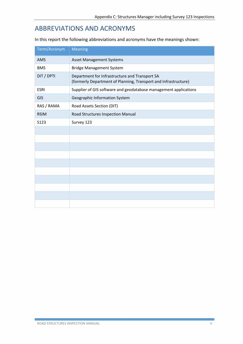
ABBREVIATIONS AND ACRONYMS
In this report the following abbreviations and acronyms have the meanings shown:
Term/Acronym Meaning
AMS Asset Management Systems
BMS Bridge Management System
DIT / DPTI Department for Infrastructure and Transport SA (formerly Department of Planning, Transport and Infrastructure)
ESRI Supplier of GIS software and geodatabase management applications
GIS Geographic Information System
RAS / RAMA Road Assets Section (DIT)
RSIM Road Structures Inspection Manual
S123 Survey 123

Appendix C: Structures Manager including Survey 123 Inspections
ROAD STRUCTURES INSPECTION MANUAL 1
1 STRUCTURES MANAGER
Inventory and condition data for all declared road structures on the South Australian state road network is stored in the Structures Manager system. This system provides accessible and timely information to all DPTI personnel involved in structures management and also makes structures’ inspection history available to inspectors.
Structures Manager also incorporates access to other structure information including past inspection reports and photographs, drawings and other pertinent information stored in folders on AWS.
Structure inspections are also completed and submitted to DPTI via Structures manager, using a Survey 123 mobile inspection form and the AWS cloud solution.
This section of the RSIM will outline the different components of Structures Manager and the manner in which inspectors will interact these components.
Prerequisites
Access to Structures Manager requires the use of a username and password which will be provided. This login will be consistent across all components of Structures Manager including Structures Map, AWS and Survey 123.

Appendix C: Structures Manager including Survey 123 Inspections
ROAD STRUCTURES INSPECTION MANUAL 2
2 STRUCTURES MAP
Figure 1: Structures Map
Structures Map is a web based map interface into Structures Manager, and is the main interface for inspectors. The map will display all structures included in inspection packages, with access to identification and inventory data for these structures. Additional information including past inspection reports, drawings and other pertinent documentation is also made available via Structures Map.
Access instructions for Structures Map will be provided with Inspection Tender documentation, to allow inspectors to view the structures included in each inspection package.
Note: At the time of writing, Google Chrome is the recommended browser.

Appendix C: Structures Manager including Survey 123 Inspections
ROAD STRUCTURES INSPECTION MANUAL 3
2.1 Structures Map Layout
Figure 2: Structures Map layout
2.2 Map and Navigation tools
(Top Left / Orange shaded area)
The icons and fields (referred to as “widgets”) located in this area enable the user to navigate around the map as follows:
Zoom in
Zoom out
Go “home” (Adelaide metro area)
Zoom to user’s current location
Search field where a user can locate an address or a structure.
Table 1: Map and navigation tools
When using the search field, structures can be searched for using the Plan ID or Structure Name.

Appendix C: Structures Manager including Survey 123 Inspections
ROAD STRUCTURES INSPECTION MANUAL 4
2.3 User Interface tools
(Top Right / Green shaded area)
The widgets located in the top right corner of the map view can be used to manage the appearance of the map.
View the map legend View the map layers, and
set layer visibility as required
View the Basemap Gallery, and change the Basemap as required
Table 2: User interface tools
Appendix C: Structures Manager including Survey 123 Inspections
ROAD STRUCTURES INSPECTION MANUAL 5
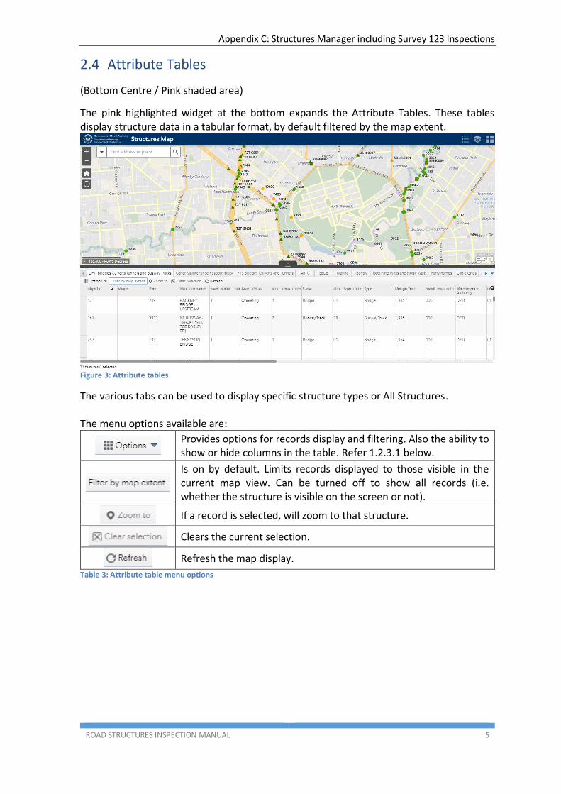
2.4 Attribute Tables
(Bottom Centre / Pink shaded area)
The pink highlighted widget at the bottom expands the Attribute Tables. These tables display structure data in a tabular format, by default filtered by the map extent.
Figure 3: Attribute tables
The various tabs can be used to display specific structure types or All Structures. The menu options available are:
Provides options for records display and filtering. Also the ability to show or hide columns in the table. Refer 1.2.3.1 below.
Is on by default. Limits records displayed to those visible in the current map view. Can be turned off to show all records (i.e. whether the structure is visible on the screen or not).
If a record is selected, will zoom to that structure.
Clears the current selection.
Refresh the map display.
Table 3: Attribute table menu options
Appendix C: Structures Manager including Survey 123 Inspections
ROAD STRUCTURES INSPECTION MANUAL 6
2.4.1 Filtering Attribute Tables
2.4.1.1 Filter by Map Extent
This is the simplest form of filtering. This is ON by default, the attribute tables will only show data for the structures visible in the current zoom level of the map.
Filtering by the map extent can easily be turned OFF by clicking the menu item, and the tables will show data for all structures, whether they are visible in the current zoom level of the map or not.
2.4.1.2 Filtering using Options
This provides more detailed filtering options.
Figure 4: Options menu
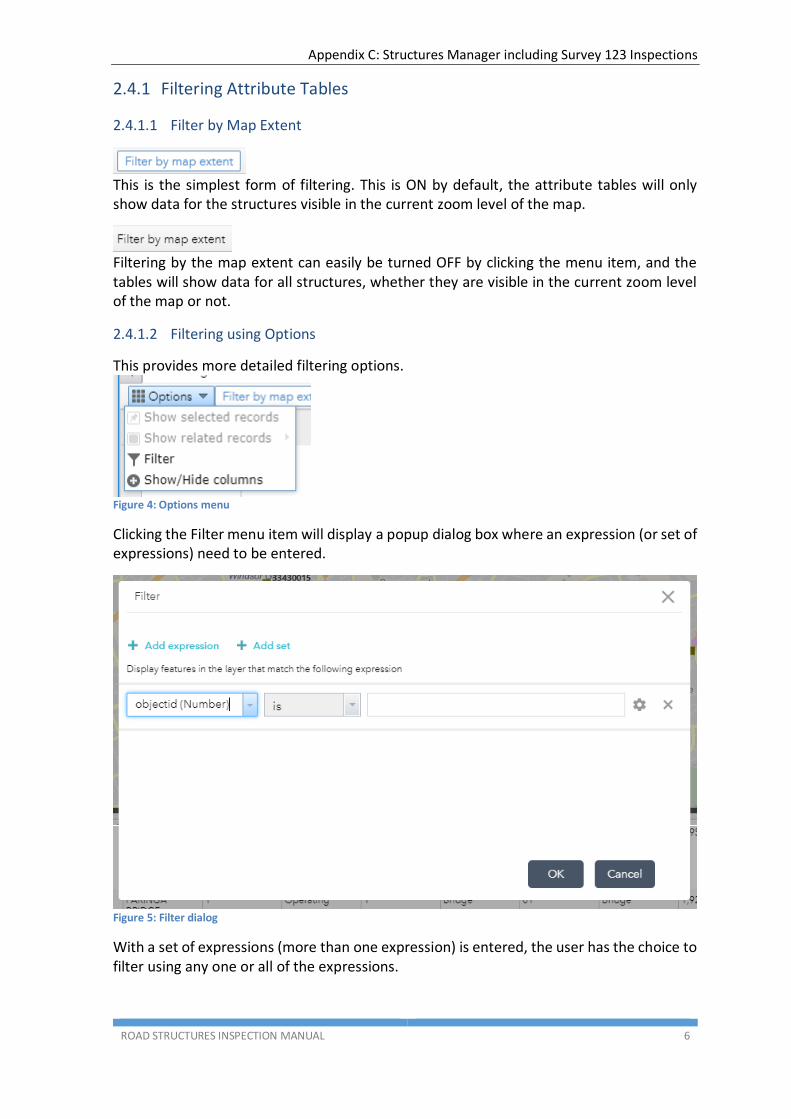
Clicking the Filter menu item will display a popup dialog box where an expression (or set of expressions) need to be entered.
Figure 5: Filter dialog
With a set of expressions (more than one expression) is entered, the user has the choice to filter using any one or all of the expressions.

Appendix C: Structures Manager including Survey 123 Inspections
ROAD STRUCTURES INSPECTION MANUAL 7
2.5 Map Information
(Left Bottom / Light Blue shaded area)
This section provides the map scale and GPS location data for the current mouse position.
Figure 6: Map information
2.6 Pop-Up Structure Data
A structure’s attributes can be viewed by locating the structure and clicking on the point that represents the Structure. The user can see attribute data in the Structure Inventory table as well as the data held in related tables.
Figure 7: Structure data pop-up
In addition to the information displayed in the popup window, there are widgets available that provide additional data:
Opens a new browser tab displaying Google Street View at the structure coordinates
Opens a new browser tab displaying the Structures Manager AWS (cloud) folders for the selected structure
Opens a new browser tab displaying the Structure Inventory Stocktake Report for the selected structure
Table 4: Pop-up widgets
Appendix C: Structures Manager including Survey 123 Inspections
ROAD STRUCTURES INSPECTION MANUAL 8
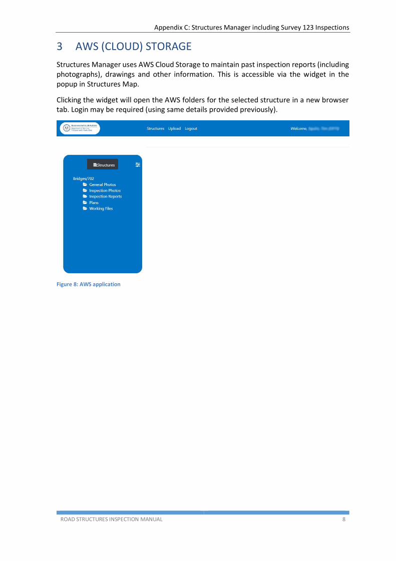
3 AWS (CLOUD) STORAGE
Structures Manager uses AWS Cloud Storage to maintain past inspection reports (including photographs), drawings and other information. This is accessible via the widget in the popup in Structures Map.
Clicking the widget will open the AWS folders for the selected structure in a new browser tab. Login may be required (using same details provided previously).
Figure 8: AWS application

Appendix C: Structures Manager including Survey 123 Inspections
ROAD STRUCTURES INSPECTION MANUAL 9
3.1 AWS Application Layout
Figure 9: AWS application layout
The AWS application screen comprises 3 main areas:
1. Structure/Folder Navigation Panel
(Left / Green shaded area)
This panel at the left side of the screen is the main navigation area of the AWS application.
It allows drill down of structure classes, to selection of folders for each structure with further drill down to document types folders for structures.
This is explained in more detail in Section 3.2 below.
2. Top Menu
(Top / Orange shaded area)
The menu items comprise Structures, Upload and Logout. These are explained in Section 3.3 below.
3. File Display
(Centre / Pink shaded area)
This area displays thumbnails or listings (depending on file types) of the files contained within the selected folder. More detail is provided in Section 3.4 below.

Appendix C: Structures Manager including Survey 123 Inspections
ROAD STRUCTURES INSPECTION MANUAL 10
3.2 Folder Navigation Panel
The folder panel on the left side of the screen is the main navigation area of the AWS application.
At its highest level, it shows a listing of folders for structure classes.
Figure 10: AWS structure class folders
3.2.1 Navigation
Returns to the Structure Class level (refer Figure 10 above)
No functionality at present
This is “breadcrumb” navigation, clicking here will navigate to the folder clicked:
Click on ‘Bridges’ to go to Plan No listing (Figure 11)
Click on ‘2827’ to go to Plan No folders (Figure 13)
Click on ‘Inspection Photos’ to go to the Inspection Photos folder (Figure 15)
Table 5: AWS folder navigation tools

Appendix C: Structures Manager including Survey 123 Inspections
ROAD STRUCTURES INSPECTION MANUAL 11
From the Structure Class level, clicking on a structure class will display a listing of folders for individual plan numbers for structures of that class.
Figure 11: AWS Gantries structure class folders Figure 12: AWS Bridges structure class folders
Clicking on a plan number folder will open folders for that structure
Figure 13: AWS plan folders
Each structure has the same set of folders to store various data types.
Appendix C: Structures Manager including Survey 123 Inspections
ROAD STRUCTURES INSPECTION MANUAL 12
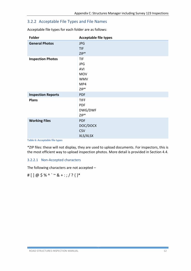
3.2.2 Acceptable File Types and File Names
Acceptable file types for each folder are as follows:
Folder Acceptable file types
General Photos JPG
TIF
ZIP*
Inspection Photos TIF
JPG
AVI
MOV
WMV
MP4
ZIP*
Inspection Reports PDF
Plans TIFF
DWG/DWF
ZIP*
Working Files PDF
DOC/DOCX
CSV
XLS/XLSX Table 6: Acceptable file types
*ZIP files: these will not display, they are used to upload documents. For inspectors, this is the most efficient way to upload inspection photos. More detail is provided in Section 4.4.
3.2.2.1 Non-Accepted characters
The following characters are not accepted –
# [ ] @ $ % ^ ` ~ & + : ; / ? { }*
Appendix C: Structures Manager including Survey 123 Inspections
ROAD STRUCTURES INSPECTION MANUAL 13
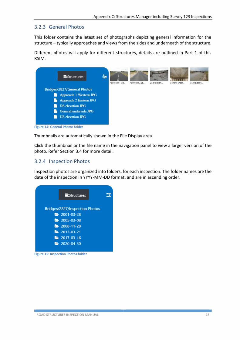
3.2.3 General Photos
This folder contains the latest set of photographs depicting general information for the structure – typically approaches and views from the sides and underneath of the structure.
Different photos will apply for different structures, details are outlined in Part 1 of this RSIM.
Figure 14: General Photos folder
Thumbnails are automatically shown in the File Display area.
Click the thumbnail or the file name in the navigation panel to view a larger version of the photo. Refer Section 3.4 for more detail.
3.2.4 Inspection Photos
Inspection photos are organized into folders, for each inspection. The folder names are the date of the inspection in YYYY-MM-DD format, and are in ascending order.
Figure 15: Inspection Photos folder

Appendix C: Structures Manager including Survey 123 Inspections
ROAD STRUCTURES INSPECTION MANUAL 14
Clicking a folder name (date) will open the folder and display its contents.
Figure 16: Inspection Photos folder contents
The folder contents are displayed in the same manner as for General Photos.
3.2.5 Inspection Reports
The Inspection Reports folder displays a listing of past inspection reports for the structure. The file (report) name has the inspection date as the first 8 characters in YYYYMMDD format, and files are listed in ascending order.
Figure 17: Inspection Reports folder
Reports are listed in both the navigation panel and the file display area. Clicking on a file name will open the report in a new browser tab.
3.2.6 Plans
This folder contains drawings for the selected structure. If drawings are required and are not present in this folder, please contact DPTI Structures on [email protected] with a request to upload the appropriate drawings.
The files are displayed in the same way as for the Inspection Reports folder.
3.2.7 Working Files
This folder contains various documents that may provide additional pertinent information regarding the selected structure.
The files are displayed in the same way as for the Inspection Reports folder.
Appendix C: Structures Manager including Survey 123 Inspections
ROAD STRUCTURES INSPECTION MANUAL 15
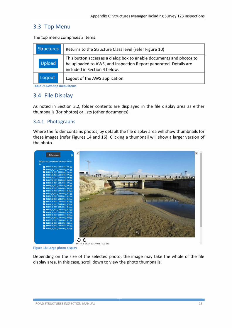
3.3 Top Menu
The top menu comprises 3 items:
Returns to the Structure Class level (refer Figure 10)
This button accesses a dialog box to enable documents and photos to be uploaded to AWS, and Inspection Report generated. Details are included in Section 4 below.
Logout of the AWS application.
Table 7: AWS top menu items
3.4 File Display
As noted in Section 3.2, folder contents are displayed in the file display area as either thumbnails (for photos) or lists (other documents).
3.4.1 Photographs
Where the folder contains photos, by default the file display area will show thumbnails for these images (refer Figures 14 and 16). Clicking a thumbnail will show a larger version of the photo.
Figure 18: Large photo display
Depending on the size of the selected photo, the image may take the whole of the file display area. In this case, scroll down to view the photo thumbnails.

Appendix C: Structures Manager including Survey 123 Inspections
ROAD STRUCTURES INSPECTION MANUAL 16
Figure 19: Large photo display scrolled
There are some basic image viewing tools available:
Print the photo
Note: if you choose to do this you should specify “Print current page” in the print dialog, otherwise ALL photos in the folder will be printed
Close the photo viewer
Note: clicking this remove all photos from the file display area. To re-enable the thumbnails, click the folder name breadcrumb (refer Section 3.2.1)
Zoom in; once clicked this icon will change to zoom out
Rotate 90° in an anti-clockwise direction
Note: this will rotate all images in the folder, if selected for larger view. To undo, rotate in the opposite direction
Rotate 90° in a clockwise direction
Note: this will rotate all images in the folder, if selected for larger view. To undo, rotate in the opposite direction
Table 8: Image viewing tools

Appendix C: Structures Manager including Survey 123 Inspections
ROAD STRUCTURES INSPECTION MANUAL 17
3.4.2 Documents
Where the folder contains documents such as inspection reports, these will display as a list (see Figure 17). Click the file name to download the file or display the document in a new browser tab.
Figure 20: AWS document display
3.5 Troubleshooting
This section contains Q & A and workarounds for reported issues.
3.5.1 AWS app opens, but nothing is displayed
An issue can arise where the user is not immediately taken to the documents that are relevant to a structure. To work around the issue, the user should log out of the document management page and then log in again. Please see the instructions below
1 Open the web map
2 Navigate to the structure in question 3 Click on the folder link (AWS opens)

Appendix C: Structures Manager including Survey 123 Inspections
ROAD STRUCTURES INSPECTION MANUAL 18
4 Click Logout (top right) straight away (note: there are two steps to logout)
5 This is the final “you’re logged out”
message.
6 Log in again (AWS opens and you can see
all the folders)
7 Go back to the map, click on the structure
again, click on the folder again in the pop up. A new window will open and the folders of information for the structure should be visible
Note: sometimes it takes a few seconds
for the folders to appear but once one set of folders is visible, subsequent document queries on other structures are much faster.
Table 9:AWS app is blank - workaround

Appendix C: Structures Manager including Survey 123 Inspections
ROAD STRUCTURES INSPECTION MANUAL 19
4 SURVEY 123
4.1 Introduction
As detailed in Part 1 Section 2.46 structure inspections must be submitted to DPTI using the Survey 123 inspection form.
Inspection types that use Survey 123 are as follows:
Level 2 – Detailed Visual Condition Inspections
Emergency/Ad-hoc Inspections
Monitoring Inspections
There are different survey forms to be used, depending on the inspection type.
This section describes how to complete the different survey forms.
4.2 Accessing Survey 123
The Survey 123 desktop or mobile application should be installed to your computer or mobile device (as applicable).
4.2.1 Initial Set Up / Log On
To use the survey, the DPTI ESRI Portal must be added to the application. This is a one off process so once it has been completed there should be no need to repeat (unless DPTI changes the survey host).
When first accessing the app, the user must “allow location services” to ensure full functionality of the app.
1 Open the Survey 123 application (desktop or mobile/tablet)
2 Tap the “Sign In” button (bottom middle
of screen)
3 Tap the “Settings” icon (top right of
screen)

Appendix C: Structures Manager including Survey 123 Inspections
ROAD STRUCTURES INSPECTION MANUAL 20
4 Tap the “Add Portal” button
5 Enter the URL (i.e. web address) of the
ESRI portal that the Survey is hosted on.
In this case, this user should use :
https://dpti.geohub.sa.gov.au/portal
6 Tap “Add Portal” 7 The list of Portals should look like the
image at the right, ensure that the newly
added Portal is highlighted
8 Tap the back arrow (top left) to return to
the log in page
9 On the log on page, enter the username
and password credentials that have been supplied by DPTI.
10 Once logged in, the User should see a
mostly blank screen with the message:
Table 10: Initial set up for Survey 123

Appendix C: Structures Manager including Survey 123 Inspections
ROAD STRUCTURES INSPECTION MANUAL 21
4.2.2 Downloading a Survey
This section assumes the steps in Section 4.2.1 have been completed.
1 Tap on the “Get Surveys” button
or
2 Click on the ‘Hamburger’ icon on the My Surveys screen and then Download Surveys
3 Select the Survey you wish to download
by clicking on the download icon
or
4 Click on the refresh icon to get the latest version of an existing Survey
5 Tap the “Back” icon (top left)
6 The survey should now be listed in ‘My
Surveys’ The inspector can access the survey by tapping on the survey icon
Table 11: Downloading a survey
Appendix C: Structures Manager including Survey 123 Inspections
ROAD STRUCTURES INSPECTION MANUAL 22
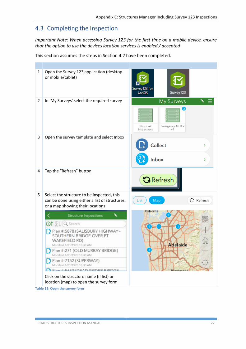
4.3 Completing the Inspection
Important Note: When accessing Survey 123 for the first time on a mobile device, ensure that the option to use the devices location services is enabled / accepted
This section assumes the steps in Section 4.2 have been completed.
1 Open the Survey 123 application (desktop or mobile/tablet)
2 In ‘My Surveys’ select the required survey
3 Open the survey template and select Inbox
4 Tap the “Refresh” button
5 Select the structure to be inspected, this
can be done using either a list of structures, or a map showing their locations:
Click on the structure name (if list) or
location (map) to open the survey form
Table 12: Open the survey form
Appendix C: Structures Manager including Survey 123 Inspections
ROAD STRUCTURES INSPECTION MANUAL 23
4.3.1 Level 2 – Detailed Visual Condition Inspection
This section assumes the inspector is conducting a Level 2 Detailed Visual Condition inspection, and has selected the appropriate survey and the required structure as detailed in Section 4.3 above.
Once the structure is selected, the inspection form opens. Note, for Level 2 inspections the form comprises 5 pages.
The inspection form is pre-filled with structure data as well as all defects and comments identified during the previous inspection.
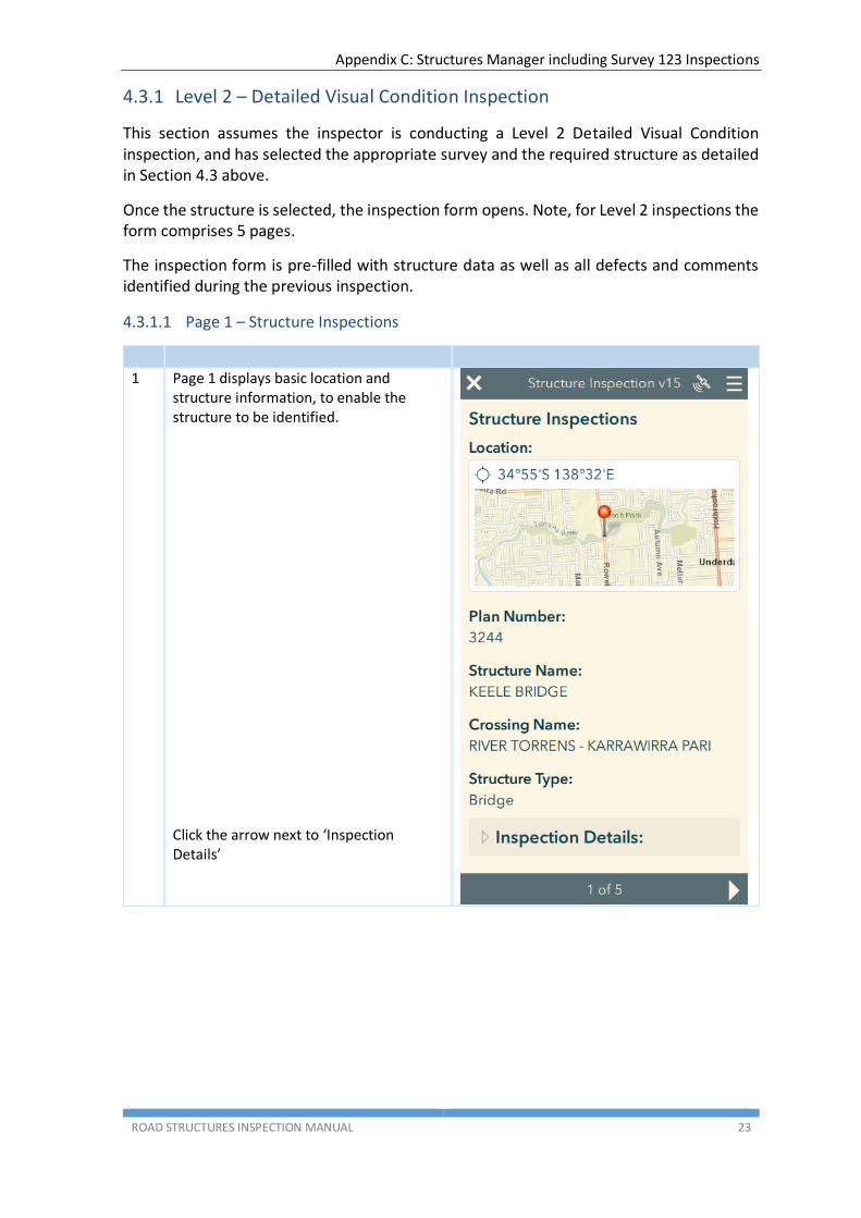
4.3.1.1 Page 1 – Structure Inspections
1 Page 1 displays basic location and structure information, to enable the structure to be identified.
Click the arrow next to ‘Inspection Details’

Appendix C: Structures Manager including Survey 123 Inspections
ROAD STRUCTURES INSPECTION MANUAL 24
2 The Inspection Details including Inspection Type (Level 2) are displayed
Enter the inspection date
Enter the inspection team member name/s
3 Move to the next page
Table 13: Level 2 - Structure Inspections page
4.3.1.2 Page 2 – Risk Assessment
1 Page 2 displays.
A risk assessment for the equipment that may be used and risks encountered when
inspecting the structure must be conducted before commencing the inspection.
Additional equipment and risks identified are to be listed.
A Risk Assessment shall be conducted and Safe Work Method Statement shall be prepared.
Inspectors conducting the inspection shall determine the equipment to be used.
The equipment listed may not necessarily be used.
Personnel undertaking the inspections have been trained and are conversant with inspection procedures and safety requirements.
2 Click the arrow next to ‘Risk Types’
Appendix C: Structures Manager including Survey 123 Inspections
ROAD STRUCTURES INSPECTION MANUAL 25
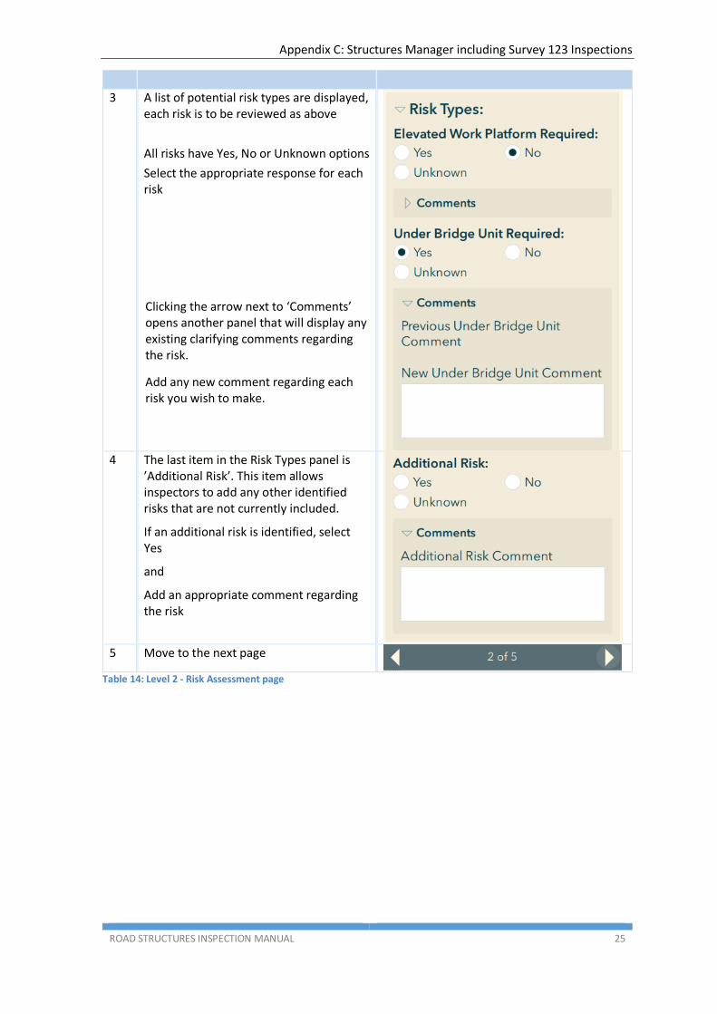
3 A list of potential risk types are displayed, each risk is to be reviewed as above
All risks have Yes, No or Unknown options
Select the appropriate response for each risk
Clicking the arrow next to ‘Comments’ opens another panel that will display any existing clarifying comments regarding the risk.
Add any new comment regarding each risk you wish to make.
4 The last item in the Risk Types panel is
’Additional Risk’. This item allows inspectors to add any other identified risks that are not currently included.
If an additional risk is identified, select Yes
and
Add an appropriate comment regarding the risk
5 Move to the next page
Table 14: Level 2 - Risk Assessment page

Appendix C: Structures Manager including Survey 123 Inspections
ROAD STRUCTURES INSPECTION MANUAL 26
4.3.1.3 Page 3 – Element Condition Assessment
As detailed in RSIM Part 1 Section 2.4.5 Inspection Procedure, structure components have been organized into Inspection Groups to allow systematic inspection along the structure.
This concept is crucial to understand, to be able to navigate this page of the survey. The diagram below shows the relationship of the inspection groups and elements, and then elements and defects and other assessment items.
Figure 21: Element Condition Assessment page structure
As can be seen, there are 3 navigation levels on this page, depicted by the arrows in the diagram. These are for inspection groups, elements and defects/comments. Inspectors need to remain aware of what inspection group/element/defect they are viewing or assessing.
1 Page 3 displays.
Inspection Group is shown
Click arrow to view Element details
Use arrows to navigate through Inspection Groups

Appendix C: Structures Manager including Survey 123 Inspections
ROAD STRUCTURES INSPECTION MANUAL 27
2
Element details are displayed*
Description – including element type, material and position
Quantity, the number of this element in this inspection group
Measurement, the total measure of these elements (or the visible surface area) in this inspection group including the unit of measure – each, metres or square metres
Is a paint assessment for this element required? **
Is monitoring of this element in place or required? **
Defects and Comments (refer Step 3)
Element Condition (refer Step 4)
Navigate through elements in this inspection group using arrows
Use these arrows to navigate through Inspection Groups
* If there are any errors with these detail (such as incorrect material, or element
quantity/measurement) the inspector should add a general comment (refer Step 4 below) advising the correct details.
** These fields are not changeable. If they are set to ‘Yes’ a separate panel similar to ‘Defects and Comments’ and ‘Element Condition’ will be included in the survey, and need to be completed. Refer Sections 4.3.1.3.1 and 4.3.1.3.2 below. If an inspector believes either of these should apply (and they are set to ‘No’) they should add a general comment (refer Step 4 below) to that effect in the ‘Defects and Comments’ section, for consideration by the Principal Engineer Structures.

Appendix C: Structures Manager including Survey 123 Inspections
ROAD STRUCTURES INSPECTION MANUAL 28
3 Defects and Comments – IMPORTANT NOTE
Element defect data was previously only captured at element level. In Structures Manager elements have been split into separate inspection groups, allowing a more accurate assessment of the location of defects during inspections.
As part of the data migration of the last full inspection data, the more granular Structures Manager model means that Inspection Comments data has been duplicated across element types in multiple inspection groups.
An example for the Deck-Voided Slab element for a 3 span bridge appears below:
OLD INSPECTION COMMENTS ELEMENT CONDITION RATING
INSERTS IN UNDERSIDE OF DECK FOR RAIL ELECTRIFICATION AND LIGHTING. SOME STARTING TO CORRODE. PHOTOS 18 & 19.
GOOD
SPALLS AT VARIOUS LOCATIONS ON SOFFIT & EDGES. PHOTOS 20, 21, 22, 23 & 24. REPAIR USING SR4.
LONGITUDINAL SOFFIT CRACKS IN CENTRE SPAN, APPROX 500MM FROM EDGE PRESENT. WORST ON NORTH SIDE. APPEARS TO LINE UP WITH LIGHTING CONDUIT. PHOTO 19.
SPALL AT SOUTH WEST KERB. PHOTO 25. REPAIR USING SR4.
DYNA BOLTS CUT FLUSH WITH DECK, ADELAIDE SIDE. PHOTO 26.

Appendix C: Structures Manager including Survey 123 Inspections
ROAD STRUCTURES INSPECTION MANUAL 29
This has been migrated into Structures Manager as follows:
INSPECTION GROUP / ELEMENT
INSPECTION COMMENTS ELEMENT CONDITION RATING
SPAN 1
Deck-Voided Slab
INSERTS IN UNDERSIDE OF DECK FOR RAIL ELECTRIFICATION AND LIGHTING. SOME STARTING TO CORRODE. PHOTOS 18 & 19.
QUANTITY IN CONDITION STATE:
1: 0
2: 1
3: 0
4: 0
5: 0
SPALLS AT VARIOUS LOCATIONS ON SOFFIT & EDGES. PHOTOS 20, 21, 22, 23 & 24. REPAIR USING SR4.
LONGITUDINAL SOFFIT CRACKS IN CENTRE SPAN, APPROX 500MM FROM EDGE PRESENT. WORST ON NORTH SIDE. APPEARS TO LINE UP WITH LIGHTING CONDUIT. PHOTO 19.
SPALL AT SOUTH WEST KERB. PHOTO 25. REPAIR USING SR4.
DYNA BOLTS CUT FLUSH WITH DECK, ADELAIDE SIDE. PHOTO 26.
SPAN 2
Deck-Voided Slab
INSERTS IN UNDERSIDE OF DECK FOR RAIL ELECTRIFICATION AND LIGHTING. SOME STARTING TO CORRODE. PHOTOS 18 & 19.
QUANTITY IN CONDITION STATE:
1: 0
2: 1
3: 0
4: 0
5: 0
SPALLS AT VARIOUS LOCATIONS ON SOFFIT & EDGES. PHOTOS 20, 21, 22, 23 & 24. REPAIR USING SR4.
LONGITUDINAL SOFFIT CRACKS IN CENTRE SPAN, APPROX 500MM FROM EDGE PRESENT. WORST ON NORTH SIDE. APPEARS TO LINE UP WITH LIGHTING CONDUIT. PHOTO 19.
SPALL AT SOUTH WEST KERB. PHOTO 25. REPAIR USING SR4.
DYNA BOLTS CUT FLUSH WITH DECK, ADELAIDE SIDE. PHOTO 26.
SPAN 3
Deck-Voided Slab
INSERTS IN UNDERSIDE OF DECK FOR RAIL ELECTRIFICATION AND LIGHTING. SOME STARTING TO CORRODE. PHOTOS 18 & 19.
QUANTITY IN CONDITION STATE:
1: 0
2: 1
3: 0
4: 0
5: 0
SPALLS AT VARIOUS LOCATIONS ON SOFFIT & EDGES. PHOTOS 20, 21, 22, 23 & 24. REPAIR USING SR4.
LONGITUDINAL SOFFIT CRACKS IN CENTRE SPAN, APPROX 500MM FROM EDGE PRESENT. WORST ON NORTH SIDE. APPEARS TO LINE UP WITH LIGHTING CONDUIT. PHOTO 19.
SPALL AT SOUTH WEST KERB. PHOTO 25. REPAIR USING SR4.
DYNA BOLTS CUT FLUSH WITH DECK, ADELAIDE SIDE. PHOTO 26.
Clearly not all comments apply across all 3 spans - for example "Longitudinal soffit cracks in centre span..." would only apply to Span 2.
Efforts have been made to correct this duplication of defects and comments however this has not always been possible, as in many cases the location of defects can only be determined while on site.
As Inspectors work through the Survey 123 Inspection form they should remain aware of the current Inspection Group they are inspecting, and that a listed existing defect or comment may not apply to the element in that particular
In these instances (where the defect or comment does not apply for the inspection group) the Inspector should select “Delete” as the Defect/Comment Status (refer below)
Appendix C: Structures Manager including Survey 123 Inspections
ROAD STRUCTURES INSPECTION MANUAL 30
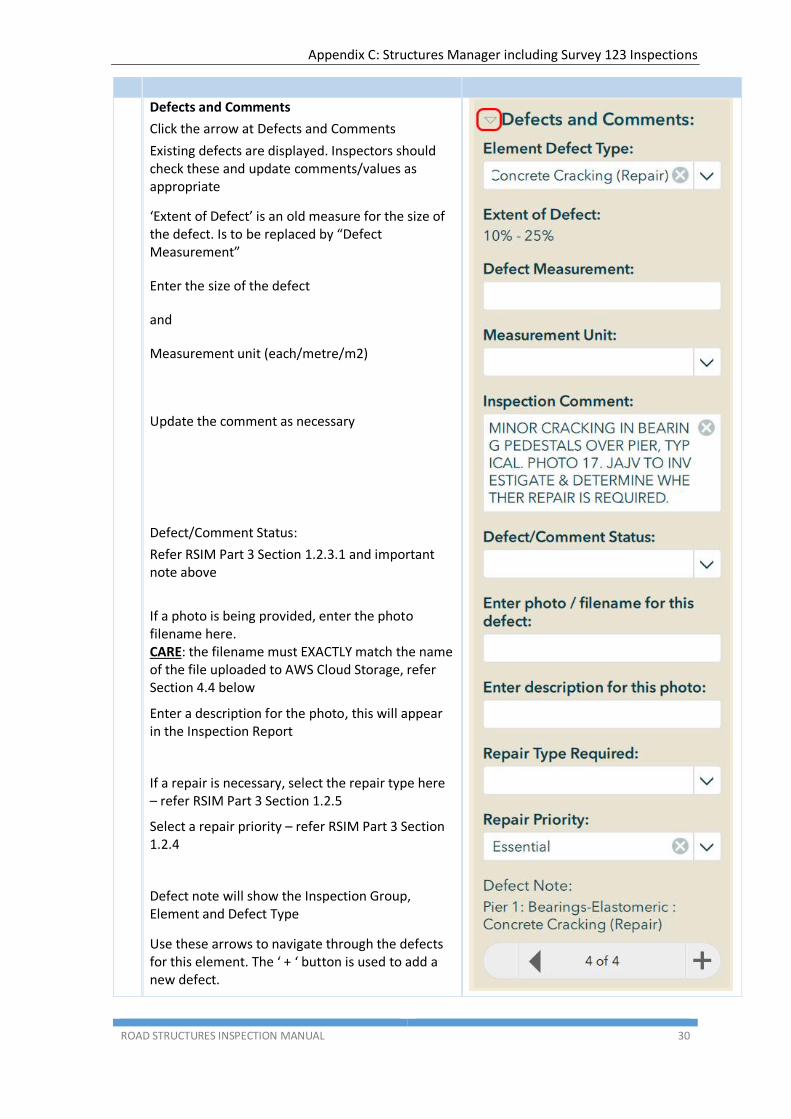
Defects and Comments
Click the arrow at Defects and Comments
Existing defects are displayed. Inspectors should check these and update comments/values as appropriate
‘Extent of Defect’ is an old measure for the size of the defect. Is to be replaced by “Defect Measurement”
Enter the size of the defect
and
Measurement unit (each/metre/m2)
Update the comment as necessary
Defect/Comment Status:
Refer RSIM Part 3 Section 1.2.3.1 and important note above
If a photo is being provided, enter the photo filename here. CARE: the filename must EXACTLY match the name of the file uploaded to AWS Cloud Storage, refer Section 4.4 below
Enter a description for the photo, this will appear in the Inspection Report
If a repair is necessary, select the repair type here – refer RSIM Part 3 Section 1.2.5
Select a repair priority – refer RSIM Part 3 Section 1.2.4
Defect note will show the Inspection Group, Element and Defect Type
Use these arrows to navigate through the defects for this element. The ‘ + ‘ button is used to add a new defect.

Appendix C: Structures Manager including Survey 123 Inspections
ROAD STRUCTURES INSPECTION MANUAL 31
4 Adding a new defect or comment
Click the ‘ + ‘ button in the element navigation bar (refer end of Step 3)
Alternatively, if there are no existing defects for the element, click the big’ + ‘
Select an Element Defect Type – refer RSIM Part 3 Section 1.2.3
Enter the size of the defect
and
Measurement unit (each/metre/m2)
Add a comment or description of the defect
If a photo is being provided, enter the photo filename here. CARE: the filename must EXACTLY match the name of the file uploaded to AWS Cloud Storage, refer Section 4.4 below
Enter a description for the photo, this will appear in the Inspection Report
If a repair is necessary, select the repair type here – refer RSIM Part 3 Section 1.2.5
Select a repair priority – refer RSIM Part 3 Section 1.2.4
To save the new defect or comment, navigate to the next section of the form (Condition Assessment). You can use the trash can to delete new defects (for example, if entered in error)
Appendix C: Structures Manager including Survey 123 Inspections
ROAD STRUCTURES INSPECTION MANUAL 32
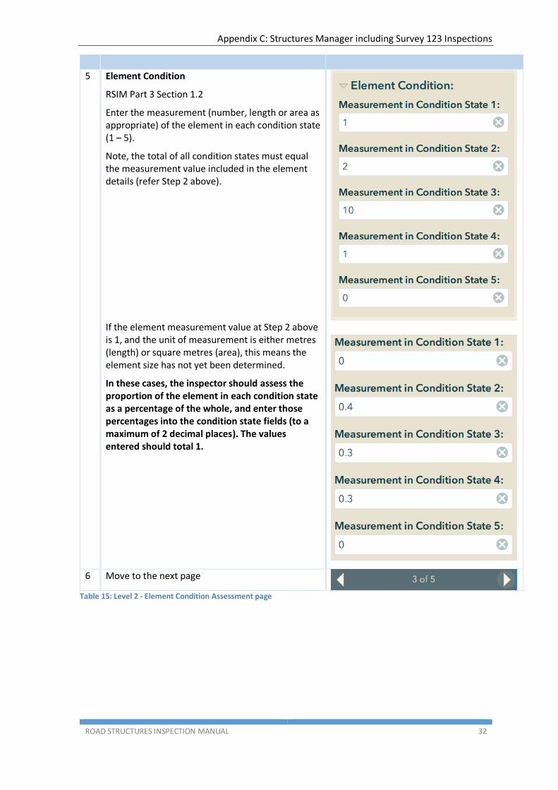
5 Element Condition
RSIM Part 3 Section 1.2
Enter the measurement (number, length or area as appropriate) of the element in each condition state (1 – 5).
Note, the total of all condition states must equal the measurement value included in the element details (refer Step 2 above).
If the element measurement value at Step 2 above is 1, and the unit of measurement is either metres (length) or square metres (area), this means the element size has not yet been determined.
In these cases, the inspector should assess the proportion of the element in each condition state as a percentage of the whole, and enter those percentages into the condition state fields (to a maximum of 2 decimal places). The values entered should total 1.
6 Move to the next page
Table 15: Level 2 - Element Condition Assessment page
Appendix C: Structures Manager including Survey 123 Inspections
ROAD STRUCTURES INSPECTION MANUAL 33
4.3.1.3.1 Element Paint Assessment
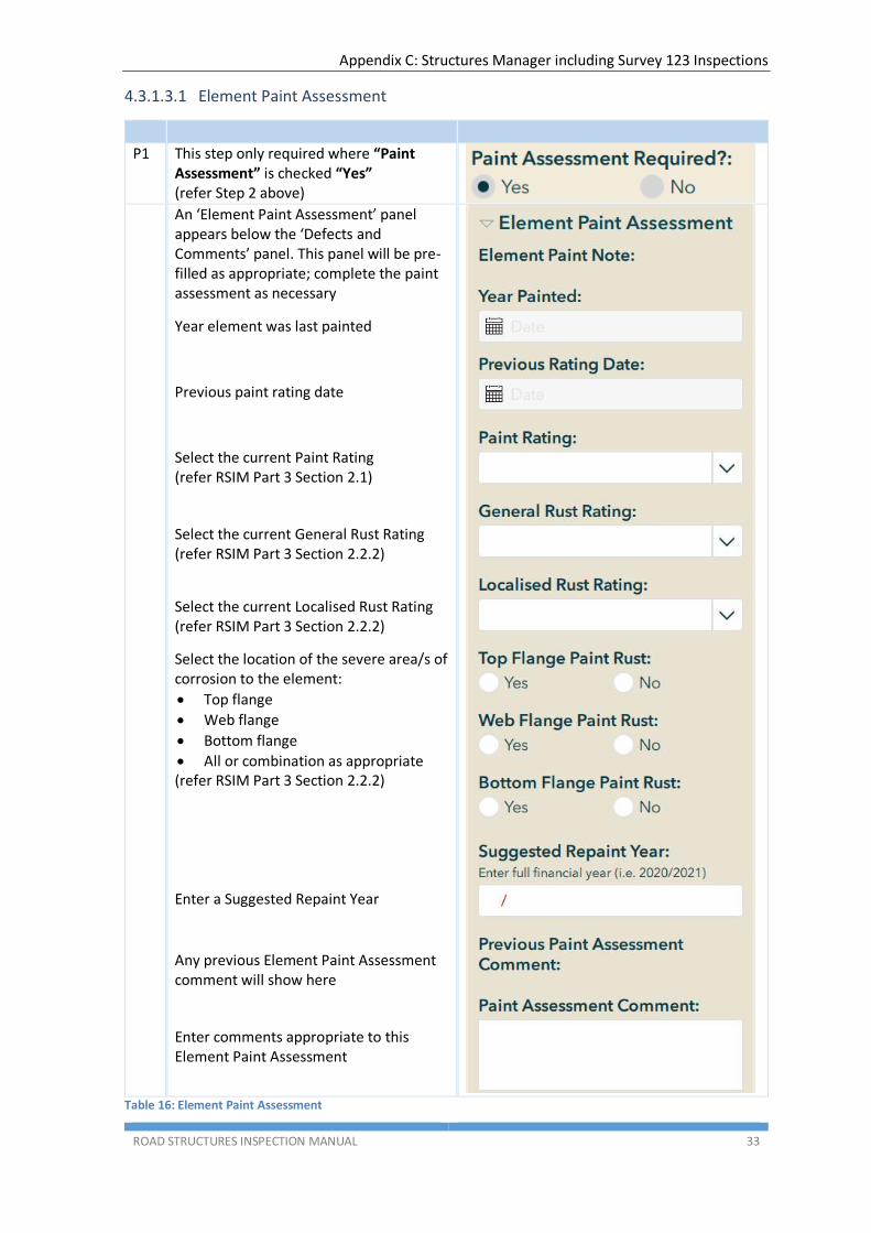
P1 This step only required where “Paint Assessment” is checked “Yes” (refer Step 2 above)
An ‘Element Paint Assessment’ panel appears below the ‘Defects and Comments’ panel. This panel will be pre-filled as appropriate; complete the paint assessment as necessary
Year element was last painted
Previous paint rating date
Select the current Paint Rating (refer RSIM Part 3 Section 2.1)
Select the current General Rust Rating (refer RSIM Part 3 Section 2.2.2)
Select the current Localised Rust Rating (refer RSIM Part 3 Section 2.2.2)
Select the location of the severe area/s of corrosion to the element:
Top flange
Web flange
Bottom flange
All or combination as appropriate (refer RSIM Part 3 Section 2.2.2)
Enter a Suggested Repaint Year
Any previous Element Paint Assessment comment will show here
Enter comments appropriate to this Element Paint Assessment
Table 16: Element Paint Assessment
Appendix C: Structures Manager including Survey 123 Inspections
ROAD STRUCTURES INSPECTION MANUAL 34
4.3.1.3.2 Monitoring Required
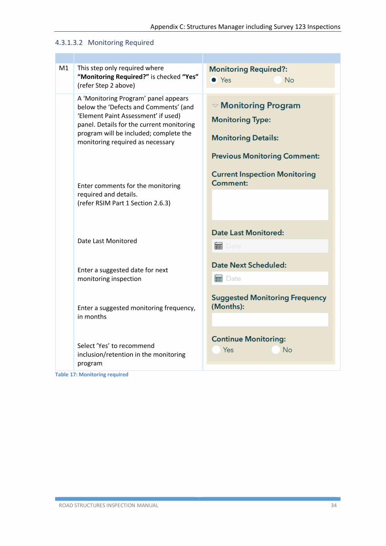
M1 This step only required where “Monitoring Required?” is checked “Yes” (refer Step 2 above)
A ‘Monitoring Program’ panel appears below the ‘Defects and Comments’ (and ‘Element Paint Assessment’ if used) panel. Details for the current monitoring program will be included; complete the monitoring required as necessary
Enter comments for the monitoring required and details. (refer RSIM Part 1 Section 2.6.3)
Date Last Monitored
Enter a suggested date for next monitoring inspection
Enter a suggested monitoring frequency, in months
Select ’Yes’ to recommend inclusion/retention in the monitoring program
Table 17: Monitoring required

Appendix C: Structures Manager including Survey 123 Inspections
ROAD STRUCTURES INSPECTION MANUAL 35
4.3.1.4 Page 4 – Overall Structure Data
1 Page 4 displays.
There are separate panels for:
Structure Photos
Structure Data
Paint Assessment
Note that not all panels apply for all structures; only those applicable to the structure type being inspected will display.
2 Structure Photos
This panel allows the addition of general structure inventory photos as outlined in RSIM Part 1 Section 2.4.8.
The photos are to be uploaded to AWS with the element defect photos. CARE: the filename must EXACTLY match the name of the file uploaded to AWS Cloud Storage, refer Section 4.4 below
Enter a description for the photo, this will appear in the Inspection Report
3 Structure Data
This panel allows data for Depth of Fill and/or Traffic Surface Seal Thickness to be added, where required
Appendix C: Structures Manager including Survey 123 Inspections
ROAD STRUCTURES INSPECTION MANUAL 36
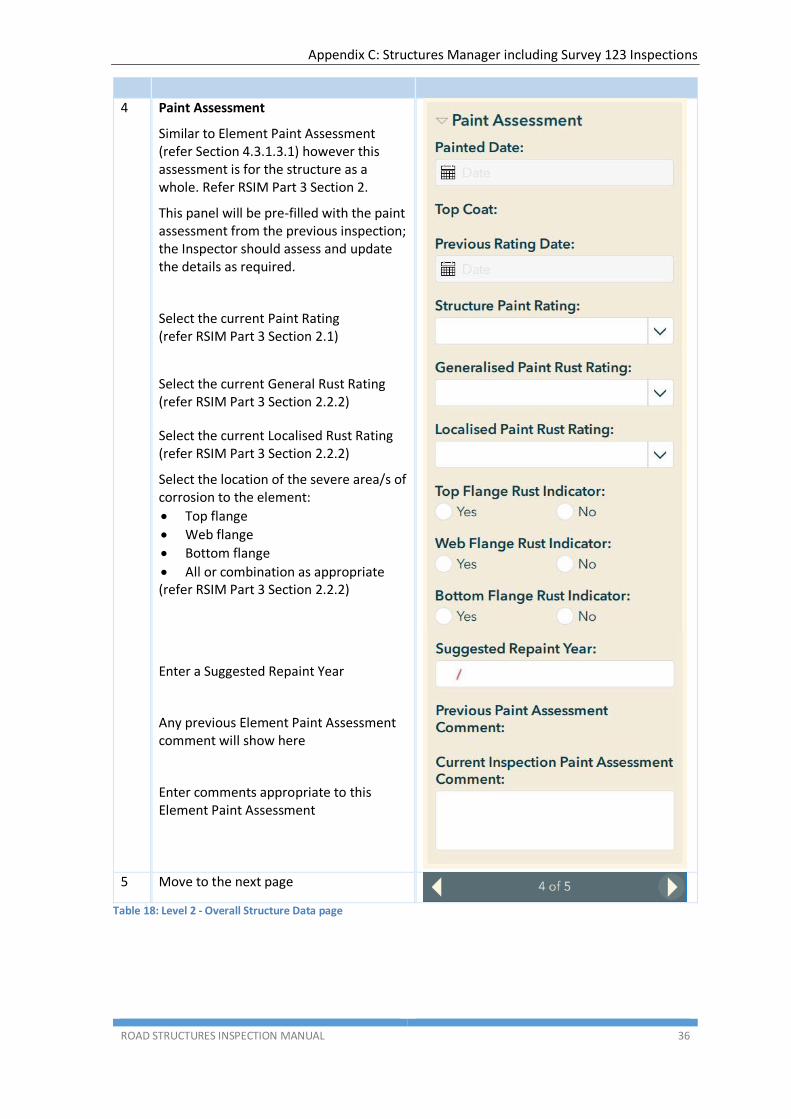
4 Paint Assessment
Similar to Element Paint Assessment (refer Section 4.3.1.3.1) however this assessment is for the structure as a whole. Refer RSIM Part 3 Section 2.
This panel will be pre-filled with the paint assessment from the previous inspection; the Inspector should assess and update the details as required.
Select the current Paint Rating (refer RSIM Part 3 Section 2.1)
Select the current General Rust Rating (refer RSIM Part 3 Section 2.2.2)
Select the current Localised Rust Rating (refer RSIM Part 3 Section 2.2.2)
Select the location of the severe area/s of corrosion to the element:
Top flange
Web flange
Bottom flange
All or combination as appropriate (refer RSIM Part 3 Section 2.2.2)
Enter a Suggested Repaint Year
Any previous Element Paint Assessment comment will show here
Enter comments appropriate to this Element Paint Assessment
5 Move to the next page
Table 18: Level 2 - Overall Structure Data page
Appendix C: Structures Manager including Survey 123 Inspections
ROAD STRUCTURES INSPECTION MANUAL 37
4.3.1.5 Page 5 – Overall Structure Inspection Summary
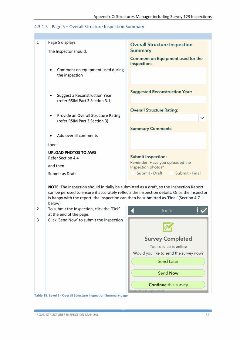
1 Page 5 displays.
The Inspector should:
Comment on equipment used during the inspection
Suggest a Reconstruction Year (refer RSIM Part 3 Section 3.1)
Provide an Overall Structure Rating (refer RSIM Part 3 Section 3)
Add overall comments
then
UPLOAD PHOTOS TO AWS Refer Section 4.4
and then
Submit as Draft
NOTE: The inspection should initially be submitted as a draft, so the Inspection Report can be perused to ensure it accurately reflects the inspection details. Once the Inspector is happy with the report, the inspection can then be submitted as ‘Final’ (Section 4.7 below)
2 To submit the inspection, click the ‘Tick’ at the end of the page.
3 Click ‘Send Now’ to submit the inspection
Table 19: Level 2 - Overall Structure Inspection Summary page
Appendix C: Structures Manager including Survey 123 Inspections
ROAD STRUCTURES INSPECTION MANUAL 38
4.3.2 Emergency/Ad-hoc Inspection
Currently, Emergency/Ad-hoc Inspections are conducted by DPTI Structural Engineers.
4.3.3 Monitoring Inspection
(This section still being developed)
4.4 Uploading the Inspection Photographs
4.4.1 Prepare the Photos for Upload
Before uploading the inspection photos to AWS Cloud Storage, the inspector first must prepare them for upload.
Reminder: Photo file names must EXACTLY match the names used in the Survey123 inspection form.
1. Ensure the individual photos meet the acceptable photo file formats listed in Section 3.2.2.
2. Using a suitable file compression utility, “zip” the photos into a “ZIP” file.
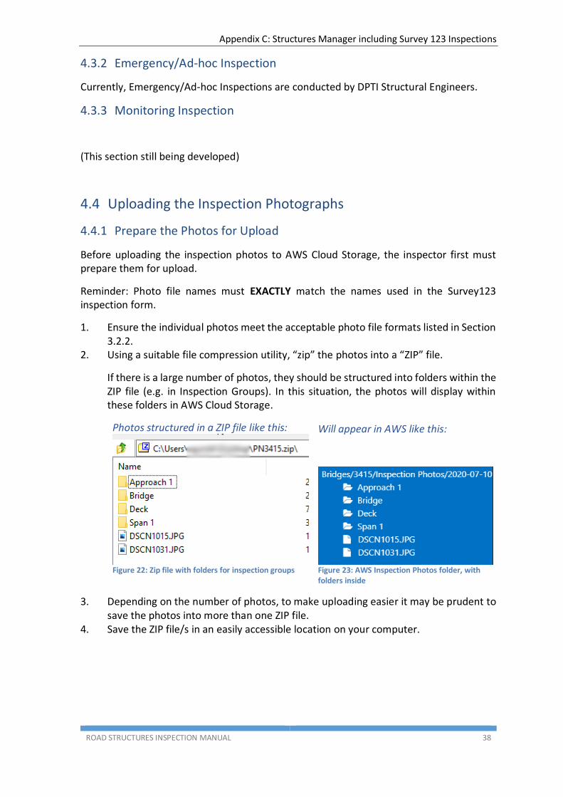
If there is a large number of photos, they should be structured into folders within the ZIP file (e.g. in Inspection Groups). In this situation, the photos will display within these folders in AWS Cloud Storage.
Photos structured in a ZIP file like this:
Figure 22: Zip file with folders for inspection groups
Will appear in AWS like this:
Figure 23: AWS Inspection Photos folder, with folders inside
3. Depending on the number of photos, to make uploading easier it may be prudent to save the photos into more than one ZIP file.
4. Save the ZIP file/s in an easily accessible location on your computer.
Appendix C: Structures Manager including Survey 123 Inspections
ROAD STRUCTURES INSPECTION MANUAL 39
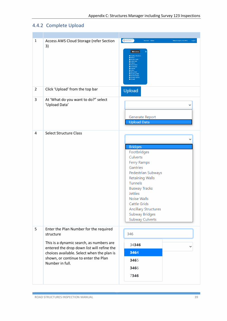
4.4.2 Complete Upload
1 Access AWS Cloud Storage (refer Section
3)
2 Click ‘Upload’ from the top bar
3 At ‘What do you want to do?” select
‘Upload Data’
4 Select Structure Class
5 Enter the Plan Number for the required
structure
This is a dynamic search, as numbers are entered the drop down list will refine the choices available. Select when the plan is shown, or continue to enter the Plan Number in full.

Appendix C: Structures Manager including Survey 123 Inspections
ROAD STRUCTURES INSPECTION MANUAL 40
6 Select the type of data to be uploaded, in this case ‘Inspection Photos’
7 Select the inspection date
NOTE: The inspection date entered MUST match the inspection date entered in the Survey123 inspection form
8 Click the ‘Choose file’ button to select a
file for upload
9 Using the dialog box, select the ZIP file prepared in Section 4.4.1 NOTE: Files can only be uploaded one at a time. If there are multiple files to be uploaded, repeat the process commencing at Step 2 above for each file.
10 The file name added (to be uploaded) will now display adjacent to the ‘Choose file’ button
11 Click the ‘Upload Data’ button
12 The button will briefly change to
‘Uploading, please wait…’ after which a status message should display
13 If an error occurs, a red banner message will show. Carefully note the details of the
message and try again later. If still unsuccessful, contact the DPTI Structures Team at [email protected]
14 You should receive an email from CBIS Notification <[email protected]> with the subject line “CBIS - Your xxxxxx.zip file upload is processed” to confirm the upload has been processed.
If there is an error and the upload fails, the email subject line will be “AWS Notification Message”. Note the details and retry, or contact the DPTI Structures Team.
Table 20: Uploading inspection photos

Appendix C: Structures Manager including Survey 123 Inspections
ROAD STRUCTURES INSPECTION MANUAL 41
4.5 Generating an Inspection Report
Once the inspection photos have been uploaded to AWS, and the inspection has been submitted in Survey 123, an inspection report can be generated.
1 Access AWS Cloud Storage (refer
Section 3)
2 Click ‘Upload’ from the top bar
3 At ‘What do you want to do?”
select ‘Generate Report’
4 Select Structure Class
Appendix C: Structures Manager including Survey 123 Inspections
ROAD STRUCTURES INSPECTION MANUAL 42
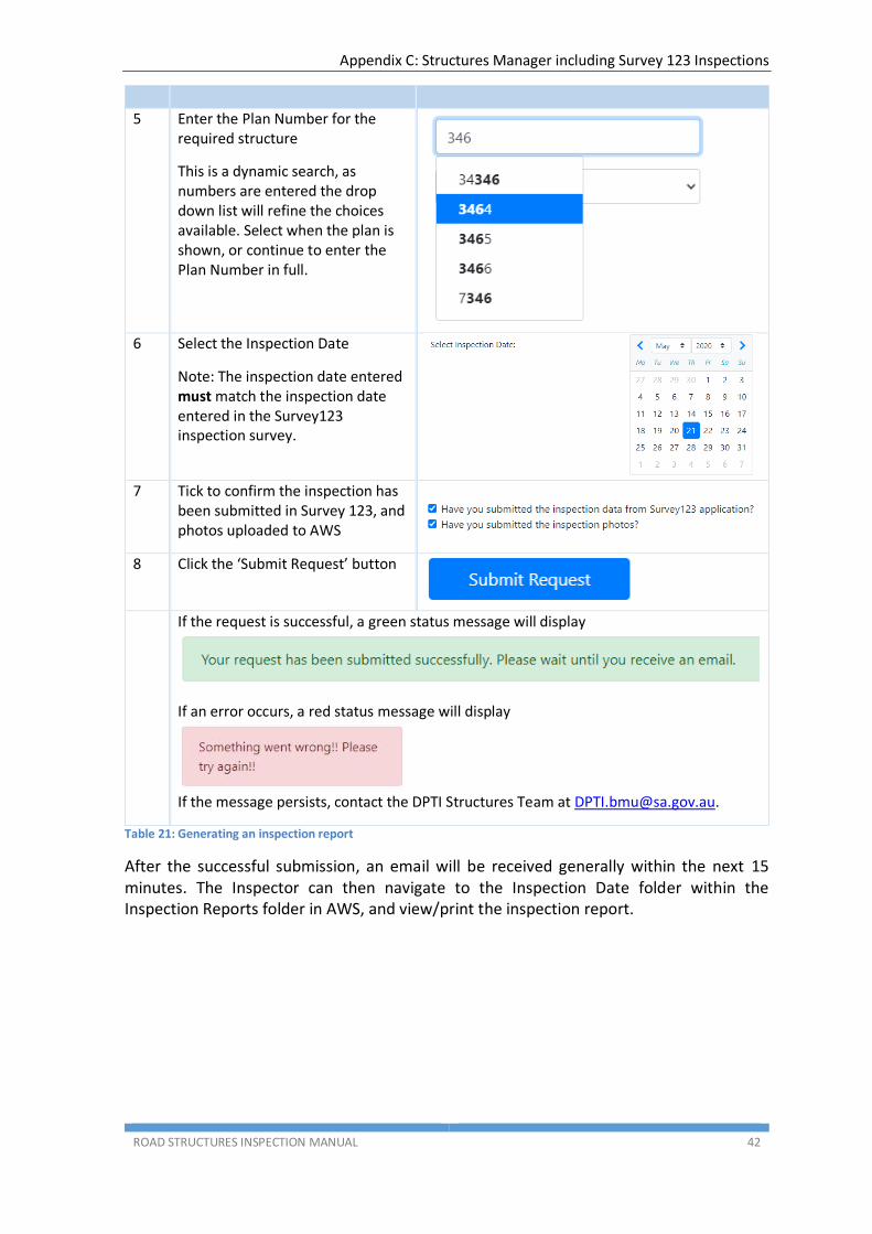
5 Enter the Plan Number for the required structure
This is a dynamic search, as numbers are entered the drop down list will refine the choices available. Select when the plan is shown, or continue to enter the Plan Number in full.
6 Select the Inspection Date
Note: The inspection date entered must match the inspection date entered in the Survey123 inspection survey.
7 Tick to confirm the inspection has
been submitted in Survey 123, and photos uploaded to AWS
8 Click the ‘Submit Request’ button
If the request is successful, a green status message will display
If an error occurs, a red status message will display
If the message persists, contact the DPTI Structures Team at [email protected].
Table 21: Generating an inspection report
After the successful submission, an email will be received generally within the next 15 minutes. The Inspector can then navigate to the Inspection Date folder within the Inspection Reports folder in AWS, and view/print the inspection report.
Appendix C: Structures Manager including Survey 123 Inspections
ROAD STRUCTURES INSPECTION MANUAL 43
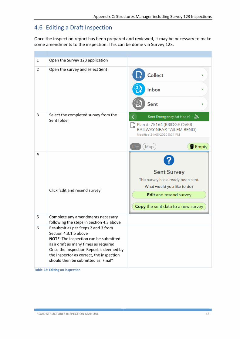
4.6 Editing a Draft Inspection
Once the inspection report has been prepared and reviewed, it may be necessary to make some amendments to the inspection. This can be dome via Survey 123.
1 Open the Survey 123 application
2 Open the survey and select Sent
3 Select the completed survey from the
Sent folder
4
Click ‘Edit and resend survey’
5 Complete any amendments necessary
following the steps in Section 4.3 above
6 Resubmit as per Steps 2 and 3 from Section 4.3.1.5 above NOTE: The inspection can be submitted as a draft as many times as required. Once the Inspection Report is deemed by the Inspector as correct, the inspection should then be submitted as ‘Final”
Table 22: Editing an inspection
Appendix C: Structures Manager including Survey 123 Inspections
ROAD STRUCTURES INSPECTION MANUAL 44
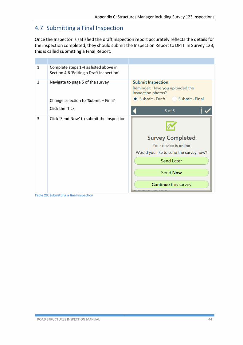
4.7 Submitting a Final Inspection
Once the Inspector is satisfied the draft inspection report accurately reflects the details for the inspection completed, they should submit the Inspection Report to DPTI. In Survey 123, this is called submitting a Final Report.
1 Complete steps 1-4 as listed above in Section 4.6 ‘Editing a Draft Inspection’
2 Navigate to page 5 of the survey
Change selection to ‘Submit – Final’
Click the ‘Tick’
3 Click ‘Send Now’ to submit the inspection
Table 23: Submitting a final inspection

Appendix C: Structures Manager including Survey 123 Inspections
ROAD STRUCTURES INSPECTION MANUAL 45
(This page has been left blank intentionally)