Embed Size (px)
Citation preview

Appendix B Waste and Water Management Plan


A p p e n d i x B
Waste and Water Management Plan,
PG&E Shell Pond and Carbon Black Area,
Bay Point, California Prepared for
Pacific Gas and Electric Company
April 2011
155 Grand Avenue, Suite 800
Oakland, CA 94612


ES113010003017BAO\111010003 iii
Contents
1.0 Introduction and Background .......................................................................................... 1-1 1.1 Background ............................................................................................................. 1-1 1.2 Objectives ................................................................................................................. 1-2
2.0 Non-Native Material Management ................................................................................. 2-1 2.1 Hydraulic Removal ................................................................................................ 2-1 2.2 Mechanical Excavation .......................................................................................... 2-2 2.3 Offsite Transportation ............................................................................................ 2-5 2.4 Disposal Management ........................................................................................... 2-5
3.0 Topsoil/Clearing and Grubbing Spoils Management ................................................. 3-1 4.0 Solid Waste and Debris Management ............................................................................ 4-1
4.1 Recycling .................................................................................................................. 4-1 4.2 Disposal ................................................................................................................... 4-1
5.0 Water Management ............................................................................................................ 5-1 5.1 Pond Water .............................................................................................................. 5-1 5.2 Gravity Thickener Overflow and Geotextile Tube Filtrate ............................... 5-2 5.3 Decontamination Water ......................................................................................... 5-3
6.0 Reference .............................................................................................................................. 6-1
Tables 1-1 Summary of Waste Stream Testing and Management ................................................... 1-2 2-1 Keller Canyon Landfill Acceptance Criteria (Title 22 Levels) ....................................... 2-3


ES113010003017BAO\111010003 1-1
1.0 Introduction and Background
This Waste and Water Management Plan presents the procedures that will be followed to test, evaluate, and manage soil, water, and other waste materials during construction of the Pacific Gas and Electric Company (PG&E) Shell Pond Corrective Action.
1.1 Background The PG&E Shell Pond project involves removal of non-native materials (NNM), including any mixed material that exceeds regulatory-agency-approved remediation goals, from a 72-acre former wastewater pond. The project also includes construction of a temporary access road and bridge, excavation of NNM from a former wastewater ditch leading to the pond, and limited fill and seeding in the Carbon Black Area, located immediately east of the pond. PG&E Shell Pond and the Carbon Black Area are regulated solid waste management units under the oversight of the California Department of Toxic Substances Control.
The pond, which was created by constructing levees along the four sides of the pond, is located within a former wetland area along the margins of San Francisco Bay (Suisun Bay), as shown on Figure 1-1 of the Proposed Corrective Measures Plan and Design (PCMPD). The pond formerly received discharges via a wastewater ditch from the Shell Oil Products Company, located on the north side of Willow Pass Road and south of the railroad tracks. The pond is bounded on the east and west sides by sloughs and channels leading to Suisun and Honker Bays.
The remedy includes the following:
Construction of a temporary road and bridge to provide safer access to the PG&E Shell Pond area
Construction of a temporary material-handling area for dewatering of hydraulically removed NNM
Removal of NNM in the portion of the wastewater ditch that is on PG&E property
Removal of NNM within the PG&E Shell Pond using both hydraulic removal and mechanical excavation in areas where hydraulic removal is not feasible
Offsite transportation and disposal of the removed NNM to a permitted disposal facility
Fill placement on the upland bare areas of the Carbon Black Area and reseeding of the upland bare areas and the bare wetland areas
Removal of approximately 82 feet of the eastern levee to provide tidal connection via the east slough and channel and restore tidal habitat
A detailed description of the remedy is presented in the Corrective Measures Study (CH2M HILL, 2010).
APPENDIX B PROPOSED CORRECTIVE MEASURES PLAN AND DESIGN WASTE AND WATER MANAGEMENT PLAN PG&E SHELL POND AND CARBON BLACK AREA
1-2 ES113010003017BAO\111010003
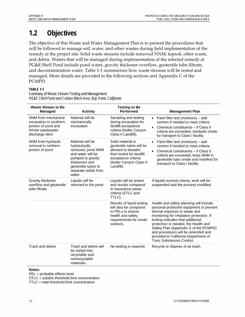
1.2 Objectives The objective of this Waste and Water Management Plan is to present the procedures that will be followed to manage soil, water, and other wastes during field implementation of the remedy at the project site. Solid waste streams include removed NNM, topsoil, other waste, and debris. Waters that will be managed during implementation of the selected remedy at PG&E Shell Pond include pond water, gravity thickener overflow, geotextile tube filtrate, and decontamination water. Table 1-1 summarizes how waste streams will be tested and managed. More details are provided in the following sections and Appendix C of the PCMPD.
TABLE 1-1 Summary of Waste Stream Testing and Management PG&E Shell Pond and Carbon Black Area, Bay Point, California
Waste Stream to Be Managed Activity
Testing to Be Performed Management Plan
NNM from mechanical excavation in southern portion of pond and former wastewater discharge ditch
Material will be mechanically excavated.
Sampling and testing during excavation for landfill acceptance criteria (Keller Canyon Class II Landfill),
Paint filter test (moisture) – add cement if needed to meet criteria.
Chemical constituents – if Class II criteria are exceeded, stockpile onsite for transport to Class I facility.
NNM from hydraulic removal in northern portion of pond
Material will be hydraulically removed; pond NNM and water will be pumped to gravity thickeners and geotextile tubes to separate solids from water.
Solid material in geotextile tubes will be allowed to dewater, then tested for landfill acceptance criteria (Keller Canyon Class II Landfill).
Paint filter test (moisture) – add cement if needed to meet criteria.
Chemical constituents – if Class II criteria are exceeded, keep NNM in geotextile tube onsite and manifest for transport to Class I facility.
Gravity thickener overflow and geotextile tube filtrate
Liquids will be returned to the pond.
Liquids will be tested and results compared to hazardous waste criteria (STLC and TTLC).
If liquids exceed criteria, work will be suspended and the process modified.
Results of liquid testing will also be compared to PELs to assess health and safety requirements for onsite workers.
Health and safety planning will include personal protective equipment to prevent dermal exposure to waste and monitoring for inhalation protection. If testing indicates that additional protection is needed, the Health and Safety Plan (Appendix G of the PCMPD) and procedures will be amended and provided to California Department of Toxic Substances Control.
Trash and debris Trash and debris will be sorted into recyclable and nonrecyclable materials.
No testing is required. Recycle or dispose of as trash.
Notes: PEL = probable effects level STLC = soluble threshold limit concentration TTLC = total threshold limit concentration

ES113010003017BAO\111010003 2-1
2.0 Non-Native Material Management
The estimated volume of NNM to be removed from the PG&E Shell Pond is 240,000 cubic yards (CY). This estimate is based on 180,000 CY of in situ NNM (including mixed native material with constituents that exceed cleanup level goals) and 60,000 CY (6 inches below NNM over the 72-acre pond bottom) of removal to account for equipment removal tolerances. Verification testing will be performed to determine whether remediation goals have been met. If an additional 0.5 foot of NNM requires removal, the total quantity could be as much as 300,000 CY.
Two technologies will be used to remove the NNM: mechanical excavation using conventional land-based equipment and hydraulic removal using horizontal auger dredges that pump material to the Material Handling Area that will be constructed on the west side of the pond. Removed NNM will be disposed of offsite at a permitted landfill.
Worker safety concerns about exposure to removed NNM are addressed in the Health and Safety Plan (Appendix G of the PCMPD). Sampling and analysis details are presented in the Sampling and Analysis Plan (Appendix C of the PCMPD). Air monitoring and dust mitigation requirements for the project are included in the Air Quality Management Plan (Appendix F of the PCMPD).
2.1 Hydraulic Removal Hydraulic removal will involve pumping the dredged material into geotextile tubes for dewatering. An estimated 197,000 CY of material will be hydraulically removed. Additional water will be required to implement hydraulic removal operations. The additional water will be pumped from the east slough at rates similar to those currently used to maintain the water cover over the NNM. The dredges will pump the material through pipes to the Material Handling Area, where the material will be mixed with a polymer additive and/or an inorganic coagulant, if needed, and into gravity thickeners. The thickener underflow will be pumped into geotextile tubes. The weep water from the tubes will be combined with the overflow from the gravity thickeners and discharged to the pond. The management of water is discussed further in Section 5.0.
2.1.1 Geotextile Tube Handling Procedures The geotextile tubes will be located in a membrane-lined and bermed containment cell equipped with a weep water collection system and sump. Pipes will be manifolded so that multiple geotextile tubes can be filled and more material can be added as the water drains from the geotextile tubes. The geotextile tubes will be stacked in the Material Handling Area, causing the weight of the tubes to force additional water from the underlying tubes. The water from the geotextile tubes (filtrate water) will be combined with the overflow from the gravity thickeners, returned via a pipe to the pond, and recirculated to allow for hydraulic removal of the remaining material. The management of water is discussed further in Section 5.0.

APPENDIX B PROPOSED CORRECTIVE MEASURES PLAN AND DESIGN WASTE AND WATER MANAGEMENT PLAN PG&E SHELL POND AND CARBON BLACK AREA
2-2 ES113010003017BAO\111010003
Waste characterization samples will be collected from the geotextile tubes. After sample results are received, the geotextile tubes will be opened and the material loaded for offsite disposal. It is anticipated that the material in the geotextile tubes will be suitable for loading and offsite disposal approximately 1 month after filling. During loading, it may be necessary to add portland cement to stabilize some of the wetter material in the center of the geotextile tubes. Based on results of pilot tests, portland cement at a volume of approximately 1 percent of the volume of in situ NNM will be adequate to stabilize the material for offsite disposal. The actual volume of portland cement used (if required) will depend on field conditions.
2.1.2 Waste Characterization Sampling Small slits will be cut in every each geotextile tube and samples of the material will be collected for analysis by an offsite laboratory. Samples of the NNM will be collected in accordance with the Sampling and Analysis Plan (Appendix C of the PCMPD). Samples will be analyzed at the frequency and for the constituents presented in Section 2.4.1. The volume of dewatered material in each geotextile tube is expected to range from approximately 1,000 CY to 1,500 CY based on the expected lengths and circumferences of tubes.
2.2 Mechanical Excavation Mechanical excavation will occur in the south end of the pond (over approximately 6 to 11 acres), where there is insufficient water (less than 18 inches) to hydraulically remove the NNM. It is estimated that 43,000 CY of NNM over 11 acres will be removed by mechanical excavation. Mechanical removal will also be performed around the perimeter of the pond, where riprap and shallow water make hydraulic removal at the edges infeasible. Approximately 300 to 600 CY of impacted material will also be removed from the former wastewater ditch by mechanical excavation.
2.2.1 Material Handling Procedures Some of the mechanically excavated material may be saturated and require stabilization to pass the paint filter test required for landfill acceptance. Based on results of pilot tests, portland cement at a volume of approximately 1 percent of the volume of in situ NNM will be adequate to stabilize the saturated material; some of the NNM will not require stabilization. The NNM will be mixed with portland cement in place. The actual volume of portland cement used (if required) will depend on field conditions. Material removed from the ditch is not anticipated to require stabilization if the removal activity occurs before the 2011 rainy season. If stabilization is necessary, it will be performed by using the same procedures and controls used for removal of material from the south end of the pond. Where present, the abandoned pipe that formed part of the former wastewater conveyance system in the former wastewater ditch will also be removed at this time and recycled, if possible, or disposed of as construction debris in accordance with the procedures presented in Section 4.0.
Based on the analytical data collected for representative samples to date, the mechanically removed and stabilized material will be suitable for direct off-haul. Material that is proposed to be mechanically excavated will be sampled in place for waste characterization prior to removal. Material that meets waste disposal criteria for Keller Canyon Landfill will be placed directly into trucks containing approximately 20 to 24 tons each for off-site

PROPOSED CORRECTIVE MEASURES PLAN AND DESIGN APPENDIX B PG&E SHELL POND AND CARBON BLACK AREA WASTE AND WATER MANAGEMENT PLAN
ES113010003017BAO\111010003 2-3
disposal. Therefore, active storage piles will not be required. However, if it is necessary to create a temporary storage pile, the storage pile will either be wetted with a dust/odor suppressant or covered with tarps to prevent dust and odor emissions.
2.2.2 Waste Characterization Sampling NNM that is proposed to be mechanically excavated will be sampled in place for waste characterization prior to removal. Samples will be analyzed at the frequency and for the constituents presented in Section 2.4.1. Sample results will then be used to obtain waste acceptance profiles. If testing indicates that the waste exceeds hazardous waste criteria, shown in Table 2-1, the material will remain onsite until manifests and transportation arrangements have been made for disposal at a Class I landfill.
TABLE 2-1 Keller Canyon Landfill Acceptance Criteria (Title 22 Levels) PG&E Shell Pond and Carbon Black Area, Bay Point, California
Organic Constituents TCLP (mg/L)
STLC (mg/L)
TTLC (mg/kg)
Aldrin N/A 0.14 1.4
Benzene 0.5
Carbon Tetrachloride 0.5
Chlordane 0.03 0.25 2.5
Chlorobenzene 100.0
Chloroform 6.0
Cresols 200.0
2,4 D 10.0 10.0 100.0
DDT, DDE, DDD N/A 0.10 1.0
1,4 Dichlorobenzene 7.5
1,2 Dichloroethane 0.5
1,1 Dichloroethylene 0.7
2,4 Dinitroltoluene 0.13
Dieldrin N/A 0.8 8.0
Dioxin N/A 0.001 0.01
Endrin 0.02 0.02 0.2
Heptachlor 0.008 0.47 4.7
Hexachlorobenzene 0.13
Hexachlorobutadiene 0.5
Hexachloroethane 3.0
Kepone N/A 2.1 21.0
Lindane 0.4 0.4 4.0

APPENDIX B PROPOSED CORRECTIVE MEASURES PLAN AND DESIGN WASTE AND WATER MANAGEMENT PLAN PG&E SHELL POND AND CARBON BLACK AREA
2-4 ES113010003017BAO\111010003
TABLE 2-1 Keller Canyon Landfill Acceptance Criteria (Title 22 Levels) PG&E Shell Pond and Carbon Black Area, Bay Point, California
Organic Constituents TCLP (mg/L)
STLC (mg/L)
TTLC (mg/kg)
Methoxychlor 10.0 10.0 100.0
Methyl Ethyl Ketone 200.0
Mirex N/A 2.1 21.0
Nitrobenzene 2.0
Pentachlorophenol 100.0 1.7 17.0
Polychlorinated Biphenyls N/A 5.0 50.0
Pyridine 5.0
Tetrachloroethylene 0.7
Toxaphene 0.5 0.5 5.0
Trichloroethylene 0.5 204.0 2040.0
2,4,5 TP (Silvex) 1.0 1.0 10.0
2,4,5 Trichlorophenol 400.0
2,4,6, Trichlorophenol 2.0
Vinyl Chloride 0.2
Inorganic Constituents Soluble Threshold
STLC (mg/L)
Trigger Levela (mg/kg)
Total Threshold
TTLC (mg/kg)
Antinomy 15.0 150.0 500.0
Arsenic 5.0 50.0 500.0
Barium 100.0 1,000.0 10,000.0
Beryllium 0.75 7.5 75.0
Cadmium 1.0 10.0 100.0
Chromium 5.0 50.0 500.0
Cobalt 80.0 800.0 8,000.0
Copper 25.0 250.0 2,500.0
Lead 5.0 50.0 350.0
Mercury 0.2 2.0 20.0
Molybdenum 350.0 3,500.0 3,500.0
Nickel 20.0 200.0 2,000.0
Selenium 1.0 10.0 100.0

PROPOSED CORRECTIVE MEASURES PLAN AND DESIGN APPENDIX B PG&E SHELL POND AND CARBON BLACK AREA WASTE AND WATER MANAGEMENT PLAN
ES113010003017BAO\111010003 2-5
TABLE 2-1 Keller Canyon Landfill Acceptance Criteria (Title 22 Levels) PG&E Shell Pond and Carbon Black Area, Bay Point, California
Organic Constituents TCLP (mg/L)
STLC (mg/L)
TTLC (mg/kg)
Silver 5.0 50.0 500.0
Thallium 7.0 70.0 700.0
Vanadium 24.0 240.0 2,400.0
Zinc 250.0 2,500.0 5,000.0
aPetroleum Hydrocarbon Thresholds: No limit; some restrictions on gasoline and jet fuel. Notes: mg/kg = milligrams per kilogram mg/L = milligrams per liter TCLP = toxicity characteristic leaching potential
2.3 Offsite Transportation NNM and transport trucks will be inspected before offsite transport to confirm that that the waste material will pass the paint filter test and that the truck cargo compartments do not have holes through which the waste could spill during transportation. In addition, loads will be covered with tarps and trucks will be inspected for potential track-out before the material leaves the project site. Prevention and removal of visible track-out onto a paved road is required before vehicles exit the work site. To prevent track-out, contaminated soil on the outside of the truck will be brushed off using a broom and soil on the tires will be removed using a high-pressure washer and a broom. Material that has been tracked out onto a paved road will be removed using wet sweeping at least once per day at the end of the workday. The material will be transported for offsite disposal in accordance with the Traffic Control and Waste Transportation Plan (Appendix D of the PCMPD).
2.4 Disposal Management Based on existing data regarding chemical quality, the material will meet acceptance criteria, for disposal at the Keller Canyon Class II Landfill. Testing during pilot studies indicated that the dewatered material meets waste acceptance criteria, and Keller Canyon Landfill has indicated that it can accept the volume of dewatered and stabilized material. Keller Canyon Landfill is located on Bailey Road, approximately 5 miles southeast of the site.
Keller Canyon Landfill could refuse shipments of NNM if they did not meet the criteria of a solid waste (i.e., failed the paint filter test) or if they are not consistent with the physical waste profile (e.g., the NNM contains debris). Material will not be refused based on chemical characteristics because the material will be pre-characterized and approved by the landfill before trucks are loaded for transport to the disposal facility.
The following measures will be implemented to ensure that the material will be classified as a solid waste:

APPENDIX B PROPOSED CORRECTIVE MEASURES PLAN AND DESIGN WASTE AND WATER MANAGEMENT PLAN PG&E SHELL POND AND CARBON BLACK AREA
2-6 ES113010003017BAO\111010003
Inspection prior to excavation and loading to evaluate the condition of the material and its suitability for excavation.
Inspection during loading to confirm that the material loaded in the truck meets solid waste criteria.
Confirmation inspection at the onsite weigh station to ensure that truck vibration during travel has not resulted in the generation of free water.
Amendment of material with portland cement, as necessary, to absorb or bind any free water. Material amendment can be performed before, during, and after loading, as necessary.
Two waste profiles will be obtained from Keller Canyon Landfill: one for NNM and another for NNM containing debris. The waste will be inspected during loading to ensure that the material will be consistent with one of the two physical waste profiles. Any large debris will be segregated from the NNM during loading.
In the event that Keller Canyon Landfill refuses numerous consecutive shipments or shipment refusal becomes too frequent, work will be stopped and additional measures will be implemented to address the reasons for shipment refusal. Additional measures may include further amendment of the material with portland cement to absorb or bind any free water and review and amendment of the waste acceptance profile(s).
2.4.1 Characterization Material characterization (both frequency and test methods) is based on Keller Canyon acceptance criteria. Additional testing may be required if material is not accepted at Keller Canyon Landfill.
Sampling and analysis details are presented in the Sampling and Analysis Plan (Appendix C of the PCMPD). Initially, one four-point composite waste characterization sample will be collected for each 2,000 CY of material. Samples will be analyzed for Title 22 metals by U.S. Environmental Protection Agency Method 6010B and volatile organic compounds (VOCs) by U.S. Environmental Protection Agency Method 8260B. Sampling frequency may be reduced and analysis for VOCs may be deleted upon review of initial data.
Two samples were collected for fish bioassay testing during pilot tests. These test results will be used to obtain waste acceptance profiles for the waste and additional fish bioassay testing will not be required.
Non-manifested hazardous wastes will not be transported over public streets because the material will be precharacterized and approved by the landfill before trucks are loaded for transport to the disposal facility.
2.4.2 Waste Acceptance Profiles Waste acceptance profiles have been obtained from Keller Canyon Landfill and will be verified prior to transfer of the removed materials to the disposal facility. Waste characterization samples will be used to obtain the profiles. It is anticipated that the removed NNM will be classified as a Class II waste. In the event that Keller Canyon Landfill cannot accept wastes based on characterization results, the removed material will be treated

PROPOSED CORRECTIVE MEASURES PLAN AND DESIGN APPENDIX B PG&E SHELL POND AND CARBON BLACK AREA WASTE AND WATER MANAGEMENT PLAN
ES113010003017BAO\111010003 2-7
and/or transported to another appropriately permitted facility. Inspection requirements, if necessary, will be followed in accordance with the waste acceptance profiles.
The contact information for the primary landfill is as follows:
Keller Canyon Landfill 901 Bailey Road Pittsburg, CA 94565 (925) 458-9800
Should any material test as California Hazardous Waste, it will be transported to the following facility:
US Ecology, Inc. Highway 95 – 12 miles south of Beatty, NV 98003
(800) 239-3943
Should more than 50 truckloads require disposal as a hazardous waste the project will require re-evaluation.
2.4.3 Waste Documentation Waste acceptance profiles will be obtained prior to transfer of the removed materials to the disposal facility. Nonhazardous waste manifests or hazardous waste manifests will be submitted to the landfill(s) with each truck and local, state, and federal laws will be followed. The waste tracking log will be updated daily.
2.4.4 Scheduling Landfill Disposal The landfill(s) will be contacted by 3:00 p.m. with the estimated number of truckloads for the following day or with the average number of trucks each day for a given week. The contact information for each landfill is listed in Section 2.4.2.

ES113010003017BAO\111010003 3-1
3.0 Topsoil/Clearing and Grubbing Spoils Management
A limited amount of topsoil with vegetation will be generated from clearing and grubbing during site preparation activities. These materials will be spread onsite according to the project plans and specifications in accordance with special provisions.

ES113010003017BAO\111010003 4-1
4.0 Solid Waste and Debris Management
Debris and other solid wastes that will be generated from site activities include an abandoned pipe that formed part of the former wastewater conveyance system and miscellaneous wastes, such as municipal waste. Small quantities of hazardous waste associated with vehicle and equipment maintenance will be generated. These wastes will be managed using PG&E’s Remote Waste Consolidation program. PG&E uses an annual notification to operate under the Health & Safety Code provisions allowing small quantities of hazardous waste to be transported without a uniform hazardous waste manifest from remote locations to a listed consolidation sites. These remote sites are located within PG&E’s operational territory, which includes most of northern and central California. There are multiple listed sites within a few miles of the project site.
Recycling
To the extent feasible, construction debris will be recycled. Other recyclable wastes, such as bottles, cans, and cardboard, and paper, will be gathered in containers for recycling.
4.1 Disposal Any construction debris that is not recyclable will be disposed of offsite as nonhazardous waste. Nonrecyclable construction debris will be disposed of offsite at Keller Canyon Landfill. Other miscellaneous wastes, such as refuse and trash, will be gathered and disposed of offsite as municipal waste.
4.2 Incidental Hazardous Waste Management Small quantities of hazardous waste generated incidental to project implementation will be managed using PG&E’s remote waste consolidation exemption (AB 1448) and will be transported to an appropriate listed facility.


ES113010003017BAO\111010003 5-1
5.0 Water Management
This section presents the procedures and requirements for managing water during NNM removal and dewatering activities. Worker safety issues related to water management during NNM removal and dewatering activities are addressed in the Health and Safety Plan (Appendix G of the PCMPD).
5.1 Pond Water The water level in PG&E Shell Pond will be managed to facilitate the type of removal – mechanical or hydraulic. Mechanical excavation will require that the water level in the pond be as low as possible to provide access for equipment and to reduce the amount of stabilization material required. Hydraulic removal will require that a minimum water level be established to provide access for the dredges.
Mechanical excavation will require that the water level in the pond be as low as possible to provide access for equipment and to reduce the amount of stabilization material required. Hydraulic removal will require a minimum depth of water of 18 inches, which translates to roughly 7 feet elevation (North American Vertical Datum of 1988), to provide access for the dredges. It is anticipated that water will be required to be added to the pond at times during hydraulic removal. Water will also be required to be added to the pond to control odors. Odor control requires that the water level reading on the staff gauge located at the northwest corner of the pond be between 0 foot and 0.3 foot. The sources of water are presented in Section 5.1.2. An odor suppressant will be used to control odors, as presented in the Air Quality Management Plan (Appendix F of the PCMPD). Two sources of water are available at the site: the Contra Costa Water District (CCWD) and the slough adjacent to the site. The slough is the preferred source of water. Construction of an onsite water supply well is also under consideration. Testing would be required to determine whether water of sufficient quantity and quality could be obtained from an onsite well.
To obtain water from the slough adjacent to the pond, California Department of Fish and Game will be notified in writing. The notification will include the design specifications for the proposed fish screen. There is no limit to the rate of use; however, there are constraints on the dates of use. Water may only be pumped from the slough from approximately the middle of August to the beginning of February.
To obtain water from CCWD, a service contract will be established. Once a service contract has been established, CCWD will install a water use meter at the site. An existing 18-inch-diameter pipeline connection is available at the site. There is no limit to the rate of use of water; however, this project is considered by CCWD as a low priority and, in years of low water availability, CCWD reserves the right to retract use.

APPENDIX B PROPOSED CORRECTIVE MEASURES PLAN AND DESIGN WASTE AND WATER MANAGEMENT PLAN PG&E SHELL POND AND CARBON BLACK AREA
5-2 ES113010003017BAO\111010003
The contact information for CCWD follows:
Contra Costa Water District 1331 Concord Ave. Concord, CA 94520 (925) 688-8000
5.2 Gravity Thickener Overflow and Geotextile Tube Filtrate The dredges will pump the material through pipes to the Material Handling Area, where the material will be mixed with a polymer additive and/or an inorganic coagulant, if needed, and into gravity thickeners. The thickener underflow will be pumped into geotextile tubes. The geotextile tubes will be stored in a membrane-lined and bermed containment area equipped with a filtrate collection system and sump. Under normal operation, the filtrate from the geotextile tubes will be combined with the overflow from the gravity thickeners and discharged to the pond. The filtrate may also be discharged separately from the gravity thickener overflow. Filtrate samples will be analyzed for the following reasons:
To verify that the liquid being returned to the PG&E Shell Pond does not exceed hazardous waste criteria
To obtain data on the types and concentrations of chemical constituents present in the filtrate to assess and, if needed, modify monitoring and worker protection criteria in the Health and Safety Plan (Appendix G of the PCMPD)
Sample collection ports will be located at the filtrate effluent, the gravity thickener overflow, and the combined flow pipe segments. During the first week of operation, a sample of the water being pumped back to the pond will be collected daily. After the first week, water samples will be collected weekly. The samples will be analyzed for Title 22 CAM 17 metals (Method SW6010B/7470), total petroleum hydrocarbons (Method SW8015B), VOCs (Method SW8260B) and polycyclic aromatic hydrocarbons (Method SW8270SIM). VOC sampling and analysis will be discontinued or performed less frequently if no significant detections are reported during the initial week’s operations. Appendix C (Sampling and Analysis Plan) of the PCMPD provides specific protocols for sampling and analysis of filtrate.
Samples will be also be collected and analyzed to monitor each flow process for system optimization. Samples of the filtrate effluent, gravity thickener overflow, and combined flow pipe segments are not points of compliance, with the exception of confirming that the filtrate is not a hazardous substance.
Based on the results of the pilot test, concentrations of contaminants in the filtrate are well below hazardous levels. However, if hazardous levels of contaminants are detected in any of the process flow samples during operations monitoring, discharge will be stopped and the water will be stored until treatment and/or offsite disposal can be arranged.
If contaminants in the combined flow are detected at concentrations higher than expected based on the pilot study, additional sampling, including sampling of filtrate effluent and gravity thickener overflow, will be performed and operational adjustments may be made.

PROPOSED CORRECTIVE MEASURES PLAN AND DESIGN APPENDIX B PG&E SHELL POND AND CARBON BLACK AREA WASTE AND WATER MANAGEMENT PLAN
ES113010003017BAO\111010003 5-3
Furthermore, operational adjustments will be made if observations of the filtrate effluent or gravity thickener overflow indicate high turbidity or increased odor.
5.3 Decontamination Water Personnel, equipment, and vehicles involved in remedial activities will be decontaminated before leaving the site. A decontamination area will be set up for personnel and small equipment within the Material Handling Area to remove all solids and wash the equipment and personal protective equipment that will leave the active work area. A decontamination area will also be set up within the south end of the pond for equipment and personnel associated with the mechanical excavation. Truck decontamination areas will be set up adjacent to the Material Handling Area and the access road loop. The truck decontamination areas will be separate from the decontamination areas for personnel and small equipment. Decontamination water will be collected and managed with the gravity thickener overflow and filtrate, in accordance with the procedures presented in Section 5.2.


ES113010003017BAO\111010003 6-1
6.0 References
CH2M HILL. 2010. Proposed Modification to Remedy Corrective Action Consent Agreement P2-03/04-006, Shell Pond, Bay Point, California. October.

Appendix C Sampling and Analysis Plan


A p p e n d i x C
Sampling and Analysis Plan, PG&E Shell Pond and Carbon
Black Area, Bay Point, California
Prepared for
Pacific Gas and Electric Company
April 2011
155 Grand Avenue, Suite 800
Oakland, CA 94612


ES113010003017BAO\111010004 iii
Contents
1.0 Introduction .................................................................................................................. 1-1
2.0 Sample Collection and Analysis ............................................................................... 2-1 2.1 Sample Collection ............................................................................................ 2-1 2.2 Sample Analysis .............................................................................................. 2-4 2.3 Sample Naming Conventions ........................................................................ 2-5 2.4 Soil Sampling Equipment ............................................................................... 2-5 2.5 Equipment Decontamination ......................................................................... 2-5 2.6 Documentation and Chain-of-Custody ........................................................ 2-6
3.0 Data Evaluation ............................................................................................................ 3-1 3.1 Confirmation Sampling .................................................................................. 3-1 3.2 Surface Water ................................................................................................... 3-1
4.0 Analytical Methods and Requirements .................................................................. 4-1 4.1 Title 22 Metals Protocol .................................................................................. 4-1 4.2 Title 22 Organic Compounds Protocol ......................................................... 4-1
Figure 1 Confirmation Sampling Locations
Tables 1 Approved Remediation Goals 2 Sample Containers, Preservation, and Holding Times 3 San Francisco Bay Basin Plan Criteria 4 Reporting Limits, Accuracy, and Precession Limits for General Chemistry 5 Reporting Limits, Accuracy, and Precision Limits for Metals –SW6000 Series and
SW7000 Series 6 Reporting Limits, Accuracy, and Precession Limits for Metals –SW6000 Series and
SW7000 Series 7 Reporting Limits, Accuracy, and Precession Limits for Title 22 TTLC Metals –
SW6000 Series and SW7000 Series 8 Reporting Limits, Accuracy, and Precession Limits for Title 22 STLC Metals –
SW6000 Series and SW7000 Series 9 Reporting Limits, Accuracy, and Precession Limits for Title 22 TCLP (RCRA) Metals
– SW6000 Series and SW7000 Series 10 Reporting Limits, Accuracy, and Precession Limits for Total Petroleum
Hydrocarbons – SW8015B 11 Reporting Limits, Accuracy, and Precession Limits for Total Petroleum
Hydrocarbons – SW8015B 12 Reporting Limits, Accuracy, and Precession Limits for Volatile Organic Compounds
– SW8260B 13 Reporting Limits, Accuracy, and Precession Limits for Volatile Organic Compounds
– SW8260B 14 Maximum Concentrations for Title 22 – Organic Compounds – SW8000 Series

APPENDIX C PROPOSED CORRECTIVE MEASURES PLAN AND DESIGN SAMPLING AND ANALYSIS PLAN PG&E SHELL POND AND CARBON BLACK AREA
iv ES113010003017BAO\111010004
15 Reporting Limits, Accuracy, and Precession Limits for Polycyclic Aromatic Hydrocarbon – SW8270SIM
16 Reporting Limits, Accuracy, and Precession Limits for Polycyclic Aromatic Hydrocarbon – SW8270SIM
17 Calibration and QC Requirements for General Chemistry and Other Parameters 18 Calibration and QC Requirements for Metals – SW6010B and EPA200.7 19 Calibration and QC Requirements for Metals – SW6020 and EPA200.8 20 Calibration and QC Requirements for Metals – SW7000 Series and EPA245.1 21 Soil Preparation Method SW3060A for Method SW7199 22 Calibration and QC Requirements for TPHs – SW8015B 23 Calibration and QC Requirements for VOCs – SW8260B 24 Calibration and QC Requirements for Polycyclic Aromatic Hydrocarbons – SW8270C
SIM

ES113010003017BAO\111010004 1-1
1.0 Introduction
This site-specific Sampling and Analysis Plan (SAP) describes the sampling that will be conducted during the field implementation of the remedy at the PG&E Shell Pond site.
The project includes removal of non-native materials (NNM), including mixed material that exceeds regulatory agency approved remediation goals, from within a 73-acre former wastewater pond. The project also includes design of a temporary access road and bridge, excavation of NNM from a former wastewater ditch leading to the pond, and limited fill and seeding in the Carbon Black Area immediately east of the pond. The PG&E Shell Pond and the Carbon Black Area are regulated solid waste management units under the oversight of the California Department of Toxic Substances Control (DTSC).
Media will be tested during implementation of the PG&E Shell Pond corrective measures. Sampling efforts will include the following:
1) Confirmation sampling to determine whether material remaining in the pond and former wastewater ditch after NNM removal meets the following remediation goals approved by DTSC:
a) Concentrations of constituents of potential concern (COPC) remaining in material in the pond should, on average, be equal to or less than the Low Ecological Preliminary Remediation Goals (EcoPRG) shown in Table 1 (all tables are located at the end of this Sampling and Analysis Plan).
b) The High EcoPRGs should not be exceeded at any location in the pond.
2) Waste characterization of NNM removed from the pond and drainage ditch.
3) Analysis of water returned to the pond to measure concentrations of re-suspended chemical constituents. Water returned to the pond includes filtrate from the dewatering process that will be recycled to the pond during hydraulic dredging, as well as water generated during decontamination of trucks, equipment, and personnel.
4) Analysis of water in the PG&E Shell Pond after NNM removal to assess whether water treatment will be needed before the pond is restored to tidal connections. Water in the adjacent eastern slough will be sampled for comparison with pond water.


ES113010003017BAO\111010004 2-1
2.0 Sample Collection and Analysis
Samples will be collected from the following media and locations:
Pond bottom soil after NNM removal (see Figure 1; located at the end of this Sampling and Analysis Plan)
Soil in the bottom of the drainage ditch after NNM removal
NNM excavated during mechanical excavation and dewatered NNM from geotextile tubes (for landfill waste acceptance)
Filtrate and decontamination water returned to the pond
Water in the pond and east slough before the berm is breached
This section presents the overall approach to sample collection and laboratory analyses during field implementation of the PG&E Shell Pond and Carbon Black Area project. The final extent of removal activities will be determined by confirmation sample results collected for laboratory analysis and compared against the remediation goals approved by DTSC (see Table 1).
All samples will be collected in laboratory-supplied containers, cooled on ice, and shipped to a California-certified laboratory under standard chain-of-custody procedures. Analytical data will be provided by the laboratory on a standard 2-week turnaround time.
2.1 Sample Collection 2.1.1 Confirmation Sampling Pond bottom or drainage ditch sampling will include areas from beneath an aqueous layer or areas inundated on a regular basis as shown on Figure 1. Sample collection will begin after NNM removal has been completed and suspended solids stirred up during hydraulic removal have settled. The timing of sample collection will be determined based on field conditions.
Generally, the following procedures will be used for soil confirmation sample collection:
Sampling equipment that might come into contact with the sample will be dedicated or decontaminated as described in Section 2.5.
At each sample location, a push core sampler or split barrel sampler will be used to collect samples at depths of 0 to 6 inches, 6 to 12 inches, and 12 to 18 inches from 33 locations within the pond (Figure 1). Samples will also be collected using the same methods at 200-foot intervals along the 1,200-foot drainage ditch on the PG&E property.
Soil samples will be collected in either acetate sample liners or 2-inch-diameter, 6-inch-long brass sleeves placed within the sampler.

APPENDIX C PROPOSED CORRECTIVE MEASURES PLAN AND DESIGN SAMPLING AND ANALYSIS PLAN PG&E SHELL POND AND CARBON BLACK AREA
2-2 ES113010003017BAO\111010004
Volatile organic compound (VOC) samples will be collected, preserved, stored, and processed in accordance with U.S. Environmental Protection Agency’s (USEPA) SW 846, Method 5035A (SW5035A).
A commercially available sampler (such as the EnCore Sampler or EasyDraw Syringe) will be used to collect the VOC sample from the sleeve or acetate liner and will be immediately transferred into a pre-weighted sample vial containing methanol or sodium bisulfate.
For all non-volatile samples, the sleeves and acetate liners containing the sample material will be sealed at each end with 2-mil Teflon film and fitted with plastic end caps.
The correct label will be affixed to each sample container to identify the sample.
The sealed sample will be placed in a zip-locked bag and placed in an iced cooler.
Using the chain-of-custody and shipping procedures described in Section 2.6, the samples will be packaged and shipped or hand-delivered to the laboratory for analysis.
Approximately 110 soil samples will be collected in the pond with 10 samples slated as duplicates for quality assurance/quality control. Four additional samples will be collected in the drainage ditch.
2.1.2 Non-Native Material Characterization Initially, one 4-point composite waste characterization sample will be collected for each 2,000 cubic yards of material from either geotextile tubes or mechanically excavated NNM from the pond and drainage ditch. Sampling frequency may be reduced and analysis for VOCs may be deleted upon review of initial data and landfill concurrence. The sampling frequency described is based on the requirements Keller Canyon Landfill. If a permitted landfill other than Keller Canyon is used, additional sampling and analysis may be required to meet that landfill’s acceptance criteria.
Generally, the following procedures will be used for waste characterization sample collection:
Sampling equipment that might come into contact with the sample (e.g., trowels, bowls) will be dedicated or decontaminated as described in Section 2.5.
Prior to sampling, the correct label will be affixed to the sample container to identify the sample.
For non-volatile samples collected from the geotextile tubes, small slits will be cut in each geotextile tube and discreet samples of the material will be collected and placed into a mixing bowl for compositing. Initially, two to three samples will be collected from each tube.
If VOC samples are deemed necessary for waste characterization, discrete samples will be collected, preserved, stored, and processed in accordance with SW5035A.

PROPOSED CORRECTIVE MEASURES PLAN AND DESIGN APPENDIX C PG&E SHELL POND AND CARBON BLACK AREA SAMPLING AND ANALYSIS PLAN
ES113010003017BAO\111010004 2-3
A commercially available sampler (such as the EnCore Sampler or EasyDraw Syringe) will be used to collect the VOC sample from the geotextile tube and will be immediately transferred into a pre-weighted sample vial containing methanol or sodium bisulfate.
For samples from the mechanical excavation area, samples of NNM will be collected from the pond bottom prior to excavation. Before samples are collected, an area estimated to include approximately 1,000 cubic yards of material (based on the average depth of NNM in the area) will be identified and divided in to quartiles. One discreet sample will be collected from each quartile and placed into a mixing bowl for compositing.
A sample of the composited material will be placed into the labeled sample container and sealed appropriately.
The sealed sample will be placed in a zip-locked bag and placed in an iced cooler.
Using the chain-of-custody and shipping procedures described in Section 2.6, the samples will be packaged and shipped or hand-delivered to the laboratory for analysis.
2.1.3 Return Water Sampling The majority of water returned to the pond during remediation activities will consist of filtrate generated from the geotextile bags during hydraulic excavation and dewatering. A smaller amount of water will be generated during decontamination of vehicles, equipment, and personnel.
Sample collection ports will be at the filtrate outflow, the gravity thickener overflow, and the combined flow pipe segments. In general, samples will be collected exclusively from the combined flow sampling port; however, based on the results of the analytical data for the return water, sampling from additional ports may be performed to evaluate the water quality of the water streams.
During the first week of operation, a sample of the water pumped back to the pond (return water) will be collected daily. After the first week, water samples will be collected weekly until return water generation has ceased.
Generally, the following procedures will be used for return water sample collection:
Samples will be collected in laboratory-provided bottles as identified in Table 2 following the protocols established in USEPA’s SW 846 methods.
Water VOC samples will be collected in accordance with USEPA’s SW 846 Method 5030B (SW5030B).
The correct label will be affixed to each sample container to identify the sample.
The sealed bottle will be adequately packaged to prevent breakage and placed in an iced cooler.
Using the chain-of-custody and shipping procedures described in Section 2.6, the samples will be packaged and shipped or hand-delivered to the laboratory for analysis.

APPENDIX C PROPOSED CORRECTIVE MEASURES PLAN AND DESIGN SAMPLING AND ANALYSIS PLAN PG&E SHELL POND AND CARBON BLACK AREA
2-4 ES113010003017BAO\111010004
2.1.4 Surface Water Sampling After confirmation sampling and before the berm is breached, four representative surface water samples will be collected from the corners of the pond. Samples will also be collected from the eastern slough adjacent to the pond.
Generally, the following procedures will be used for surface water sample collection:
Samples will be collected in a clean, disposable sampling container (e.g., bailer, jar) and poured into laboratory-provided bottles as identified in Table 2. Sampling, handling, and analysis procedures will follow the protocols established in USEPA’s SW 846 methods.
The correct label will be affixed to each sample container to identify the sample.
The sealed bottle will be adequately packaged to prevent breakage and placed in an iced cooler.
Using the chain-of-custody and shipping procedures described in Section 2.6, the samples will be packaged and shipped or hand-delivered to the laboratory for analysis.
2.2 Sample Analysis 2.2.1 Confirmation Sampling The surface soil samples (0 to 6 inches) will be analyzed for Title 22 CAM 17 metals (SW6010B/7470), total petroleum hydrocarbons (TPH) (SW8015B), VOCs (SW8260B), and polycyclic aromatic hydrocarbon (PAH) (SW8270SIM). The deeper samples will be held at the laboratory pending the results of the surface sample analyses. The deeper sample will be analyzed only if the average of surface sample concentrations fails to meet the Low EcoPRG concentrations presented in Table 1.
2.2.2 Non-Native Material Characterization The NNM characterization samples will be analyzed for Title 22 CAM 17 metals (SW6010B/7470) and VOCs ( SW8260B). Analysis for VOCs may be deleted upon review of initial data and landfill concurrence.
2.2.3 Return Water Sampling Return water samples will be analyzed for Title 22 CAM 17 metals (SW6010B/7470), TPH (SW8015B), VOCs (SW8260B), and PAHs (SW8270SIM). VOCs may be discontinued or collected less frequently if no significant detections are reported during the initial week’s operations.
2.2.4 Surface Water Sampling Surface water samples will be analyzed for Title 22 CAM 17 metals ( SW6010B/7470), TPH (SW8015B), VOCs (SW8260B), and PAHs (SW8270SIM). The analytical results from the surface water sampling will be evaluated as described in Section 3.0.

PROPOSED CORRECTIVE MEASURES PLAN AND DESIGN APPENDIX C PG&E SHELL POND AND CARBON BLACK AREA SAMPLING AND ANALYSIS PLAN
ES113010003017BAO\111010004 2-5
2.3 Sample Naming Conventions Samples collected during the confirmation sampling will comply with the naming convention described below.
Pond Soil SP-PX-Y = PG&E Shell Pond - Location X (where X = Grid ID [vertical letter and horizontal number]) – Depth Y (where Y = depth of top of sample in feet: 0, 0.5, 1)
Former Wastewater Drainage Ditch Soil SP-DX-Y = PG&E Shell Pond - Location X (where X = 1, 2, 3, etc.) - Depth Y (where Y = depth of top of sample in feet: 0, 0.5, 1)
Return Water SP-RWX-Date = PG&E Shell Pond - Sample Number X (where X = 1, 2, 3, etc.) - Sample Date (= 101511 for October 15, 2011, etc.)
Surface Water SP-SWX-Date = PG&E Shell Pond – Surface Water X (where X = NW, SW, NE, and NW) - Sample Date (= 101511 for October 15, 2011, etc.)
Non-Native Material in Geotubes SP-GTX-Date = PG&E Shell Pond - Sample Number X (where X = 1, 2, 3, etc.) - Sample Date (= 101511 for October 15, 2011, etc.)
Non-Native Material from Mechanical Excavation SP-NMX-Date = PG&E Shell Pond - Location X - Sample Date (= 101511 for October 15, 2011, etc.)
2.4 Soil Sampling Equipment Sampling equipment will be either disposable or decontaminated. Soil sampling equipment will consist of the following:
Trowels (stainless-steel or Teflon coated) or push core samplers EasyDraw Syringe for VOCs Sample container (supplied by the laboratory for the requested analysis) Sample gloves (disposable surgical gloves or equivalent)
2.5 Equipment Decontamination Reusable field equipment used to collect and handle samples or collect field measurements will be decontaminated before coming into contact with any sample. The equipment decontamination procedures are as follows:
1. Clean equipment in bath of tap water (i.e., drinking water) and detergent (i.e., Alconox or equivalent). Equipment should be free of residual dirt or contamination. Re-wash as necessary.
APPENDIX C PROPOSED CORRECTIVE MEASURES PLAN AND DESIGN SAMPLING AND ANALYSIS PLAN PG&E SHELL POND AND CARBON BLACK AREA
2-6 ES113010003017BAO\111010004
2. Rinse equipment with tap water.
3. Air-dry the equipment, and wrap in plastic, if not immediately used.
2.6 Documentation and Chain-of-Custody A required part of any sampling and analytical program is the integrity of the sample from collection to data reporting. This includes the ability to trace the possession and handling of samples from the time of collection through analysis and final disposition. This documentation of the sample’s history is referred to as chain-of-custody.
The components of the chain-of-custody (custody seals, a field log book, chain-of-custody record) and the procedures for their use are described in the following paragraphs. A sample is considered to be under a person’s custody if it is:
In a person’s physical possession. In view of the person after the person has taken possession. Secured by that person so that no one can tamper with the sample.
A person who has samples under custody must comply with the procedures described in the following sections.
2.6.1 Chain-of-Custody Record To establish the documentation necessary to trace sample possession from the time of collection, a chain-of-custody record will be filled out and will accompany every sample (soil and water).
The record will contain the following information:
Station location (tied to a sampling location) Signature of collector(s) Date and time of collection Sample identification number Number of containers Project name and number Name of shipper (remarks) Date shipped (remarks) Signature of people involved in the chain of possession Inclusive dates and times of possession Federal Express bill number
To maintain chain-of-custody, each person in custody of the sample will sign, date, and note time on the form. Samples will not be left unattended unless placed in a sealed container secured with custody seals with the chain-of-custody record inside the container.
2.6.2 Custody Seals Custody seals will be used to detect unauthorized tampering of samples following sample collection up to the time of analysis. The seal will be attached so that it must be broken to open the sample shipping container. Seals will be affixed to each shipping container (i.e.,

PROPOSED CORRECTIVE MEASURES PLAN AND DESIGN APPENDIX C PG&E SHELL POND AND CARBON BLACK AREA SAMPLING AND ANALYSIS PLAN
ES113010003017BAO\111010004 2-7
each ice chest) before the samples leave the custody of the sample personnel. A seal will include:
Sampler’s signature Date of collection
2.6.3 Field Log Book All information pertinent to the field sampling effort will be recorded in a log book or equivalent standardized form. Each page/form will be consecutively numbered. Entries will be made in indelible ink, and corrections will consist of line-out deletions initialed and dated. Entries in a log book may include:
Purpose of sampling
Location and description of the sampling point
Name and address of field contact
Documentation of procedures for preparation of reagent or supplies that become an integral part of the sample (e.g., field blanks)
Identification of sampling crew members
Type of sample (e.g., soil)
Number of sample taken
Sample type taken (e.g., primary sample, duplicate)
Date and time of collection
Weather conditions
Reference such as maps of the sampling site
Field observations
Any field measurements made
Signature and date by the personnel responsible for observations
Sampling situations vary widely. No general rules can specify the extent of information that must be entered into a log book or standardized form. However, records will contain sufficient information so that the sampling activity can be reconstructed without relying on the collector’s memory.


ES113010003017BAO\111010004 3-1
3.0 Data Evaluation
3.1 Confirmation Sampling The analytical results of confirmation samples will be evaluated post-excavation. The first evaluation will be a point estimate comparison. Each COPC reported in the confirmation samples will be compared to the High EcoPRGs presented in Table 1 to evaluate if further excavation is necessary at that sample location. In addition, the average of all constituent concentrations will be compared to the Low EcoPRGs presented in Table 1. If the average concentration of a COPC is above the Low EcoPRG, an excavation plan will be developed for the areas with the highest COPC concentrations and implemented to achieve the approved remediation goals.
3.2 Surface Water The water in the pond will be tested after NNM removal to verify that it meets the San Francisco Bay Regional Water Quality Control Board (RWQCB) Basin Plan criteria presented in Table 3 or is comparable in quality to water in the adjacent slough. If the water in the pond exceeds Basin Plan criteria for metals or if petroleum hydrocarbons are detected at concentrations above those in the eastern slough, water in the pond will require treatment prior to discharge to the levee. These criteria are contained in the water quality certification permit submitted to the San Francisco RWQCB. This permit is under review and will not be completed until the California Environmental Quality Act (CEQA) process is complete. Should the RWQCB recommend different criteria in the permit, this plan will be amended and provided to DTSC.


ES113010003017BAO\111010004 4-1
4.0 Analytical Methods and Requirements
This section provides the quality assurance project plan (QAPP) of the SAP. It specifies project-specific analytes and analytical methods. Requirements for sample containers, preservation techniques, sample volumes, and holding times are presented in Table 2.
The reporting limits, calibration, preliminary cleanup goals, accuracy and precision limits, and quality control (QC) acceptance criteria are provided in Tables 4 through 24.
4.1 Title 22 Metals Protocol California waste characterization protocol specifies a stepped procedure for the determination of hazardous waste disposal as follows:.
1. As necessary based on site conditions and generator knowledge, analyze the sample for the Title 22 metals – total threshold limit concentration (TTLC) (Table 7).
2. If a TTLC sample result is greater than 10 times the soluble threshold limit concentration (STLC) (Table 8), extract and analyze the sample using the Waste Extraction Test (WET) for that metal.
3. If a TTLC sample result is greater than 20 times the toxicity characteristic leaching procedure (TCLP) concentration (Table 9), extract the sample by TCLP Method 1311 and analyze for the specific metal that exceeds the STLC threshold.
4.2 Title 22 Organic Compounds Protocol Like the metals, the California waste characterization protocol for organic compounds specifies a stepped procedure for the determination of hazardous waste disposal as follows:
1. Use site conditions (investigation results) and generator knowledge to determine the organic analysis required (see Table 14).
2. If a TTLC sample result is greater than 10 times the STLC concentration (Table 14), extract and analyze the sample using the WET for that analyte.
3. If a TTLC sample result is greater than 20 times the TCLP concentration (Table 14), extract the sample by TCLP Method 1311 and analyze for the specific analyte that exceeds the TTLC or STLC threshold.


Figure


ES102109034456BAO confirmation_sampling_locs.ai 01-05-11 dash
Confirmation sampling locationFIGURE 1 Confirmation Sampling LocationsPG&E Shell Pond and Carbon Black Area ProjectBay Point, California


Tables


PROPOSED CORRECTIVE MEASURES PLAN AND DESIGN APPENDIX C PG&E SHELL POND AND CARBON BLACK AREA SAMPLING AND ANALYSIS PLAN
ES113010003017BAO\111010004 TABLES-1
TABLE 1 Approved Remediation Goals
PG&E Shell Pond and Carbon Black Area, Bay Point, California
Parameter Low EcoPRG
(mg/kg) High EcoPRG
(mg/kg)
Chromium 217 370
Cobalt 30 42.6
Copper 68.1 270
Lead 43.2 218
Mercury 0.43 0.71
Molybdenum 9.3 23,000
Nickel 129 516
Sulfide n.a. 4.5
1-Methylnaphthalene 0.021 0.094
2-Methylnaphthalene 0.07 0.67
Acenaphthene 0.016 0.5
Acenaphthylene 0.044 0.64
Fluorene 0.019 0.54
Naphthalene 0.16 2.1
Phenanthrene 0.24 1.5
LMW PAHs 0.552 3.16
Benzo(a)pyrene 0.43 1.6
Benzo(b)fluoranthene 0.13 1.107
Benzo(g,h,i)perylene 0.067 0.497
Chrysene 0.384 2.8
Indeno(1,2,3-cd)pyrene 0.068 0.488
Pyrene 0.665 2.6
TPH as Gasolinea 400
TPH as Diesela 500
TPH as Motor Oila 2,500
HMW PAHs 1.7 9.6
Total PAHs 4.022 44.792
aBased on San Francisco RWQCB environmental screening level guidance for protection of surface water (Screening for Environmental Concerns at Sites with Contaminated Soil and Groundwater” Interim Final, November 2007, Revised May 2008) Section 8.
Notes:
HMW PAHs = High molecular weight - polycyclic aromatic hydrocarbons (benzo(a)anthracene, benzo(a)pyrene, chrysene, dibenz(a,h)anthracene, fluoranthene, and pyrene)
LMW PAHs = Low molecular weight - polycyclic aromatic hydrocarbons (acenaphthylene, acenaphthene, anthracene, fluorene, naphthalene, and phenanthrene)
mg/kg = milligrams per kilogram

PROPOSED CORRECTIVE MEASURES PLAN AND DESIGN APPENDIX C PG&E SHELL POND AND CARBON BLACK AREA SAMPLING AND ANALYSIS PLAN
TABLES-2 ES113010003017BAO\111010004
TABLE 2 Sample Containers, Preservation, and Holding Times PG&E Shell Pond and Carbon Black Area, Bay Point, California
Analyte Method
Container and Minimum Quantity
Preservation Holding Time Water Soil
Metals (except hexavalent chromium)
SW6010B, SW6020A, EPA200.7, EPA200.8, SM3120B, EPA245.1, SW7000 series methods
1-liter P or G 8-oz/P, G, or T Water: Add HNO3 to pH<2; soil: None
28 days for mercury; 180 days for all others
Extractable TPH SW8015B Two 1-liter G 8-oz/G or T Chill to 4C (±2C) Water: 7 days to extraction; 40 days to analysis
Soil: 14 days to extraction; 40 days to analysis
VOCs SW8260B
Preparation methods:
SW5035A (Soil)
SW5030B (Water)
Three 40-ml Glass-TLC
4 EnCore samplers or equivalent; see Sections 2.1 and 2.4
Water: Add HCl to pH<2; chill to 4C (±2C)
Soil/sediment: Chill to 4C (±2C)
Water: 14 days (preserved); 7 days (unpreserved)
Soil:
48 hours if only cooled to 4ºC
48 hours by Encore or equivalent sampler unless extruded and preserved with 48 hours
14 days if solid samples preserved by the following methods:
4ºC/frozen in 48 hours
Frozen onsite
Sodium bisulfate
Methanol
PAH SW8270SIM Two 1-liter G 8-oz G or T Chill to 4C (±2C) Water: 7 days to extraction; 40 days to analysis
Soil: 14 days to extraction; 40 days to analysis

CORRECTIVE MEASURES IMPLEMENTATION PLAN APPENDIX C PG&E SHELL POND AND CARBON BLACK AREA CONFIRMATION SAMPLING AND ANALYSIS AND QUALITY ASSURANCE PROJECT PLAN
ES113010003017BAO\111010004 TABLES-3
TABLE 2 Sample Containers, Preservation, and Holding Times PG&E Shell Pond and Carbon Black Area, Bay Point, California
Analyte Method
Container and Minimum Quantity
Preservation Holding Time Water Soil
Anions EPA300.0 or SM4500 500-ml P or G 4-oz P, G, or T Chill to 6C (none required for chloride and fluoride)
orthophosphate requires filtering within 15 minutes after sample collection
Bromide, chloride, fluoride, sulfate, and iodide in 28 days
Nitrate and orthophosphate in water 48 hours
TSS SM2540 D 500-ml P or G Chill to 6C 7 days
Turbidity EPA180.1 Revision 2 or SM2130 500-ml P or G Chill to 6C 48 hrs
Specific Conductance EPA120.1 Revision 1, or SM2510 500-ml P or G Chill to 6C 28 days
Notes: = greater than < = less than = less than or equal to G = glass HNO3 = nitric acid ml = milliliter oz = ounce P = polyethylene SIM = selected ion monitoring T = brass sleeves TLC = teflon-lined container TSS = total suspended solids

PROPOSED CORRECTIVE MEASURES PLAN AND DESIGN APPENDIX C PG&E SHELL POND AND CARBON BLACK AREA SAMPLING AND ANALYSIS PLAN
TABLES-4 ES113010003017BAO\111010004
TABLE 3 San Francisco Bay Basin Plan Criteria PG&E Shell Pond and Carbon Black Area, Bay Point, California
Analyte Basin Plan Units
Arsenic 36 µg/L
Cadmium 9.3 µg/L
Copper 9 µg/L
Lead 8.1 µg/L
Mercury 0.025 µg/L
Nickel 8.2 µg/L
Silver 1.9 µg/L
Zinc 81 µg/L
Total PAHs 15 µg/L
TPH as diesel -- µg/L
TPH as motor oil -- µg/L
Chloride -- mg/L
Notes: µg/L = micrograms per liter mg/L = milligrams per liter Sources: Sa n Francisco Bay Regional Water Quality Control Board. 2010. San Francisco Bay Basin Water Quality Control Plan. Basin Plan Update Surface Water Bodies and Beneficial Uses. February 24. San Francisco Bay Regional Water Quality Control Board. 2007. San Francisco Bay Basin (Region 2) Water Quality Control Plan (Basin Plan). January 18.
PROPOSED CORRECTIVE MEASURES PLAN AND DESIGN APPENDIX C PG&E SHELL POND AND CARBON BLACK AREA SAMPLING AND ANALYSIS PLAN
ES113010003017BAO\111010004 TABLES-5
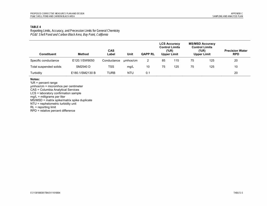
TABLE 4 Reporting Limits, Accuracy, and Precession Limits for General Chemistry PG&E Shell Pond and Carbon Black Area, Bay Point, California
Constituent Method CAS Label Unit QAPP RL
LCS AccuracyControl Limits
(%R) Upper Limit
MS/MSD Accuracy Control Limits
(%R) Upper Limit
Precision WaterRPD
Specific conductance E120.1/SW9050 Conductance µmhos/cm 2 85 115 75 125 20
Total suspended solids SM2540 D TSS mg/L 10 75 125 75 125 10
Turbidity E180.1/SM2130 B TURB NTU 0.1 20
Notes: %R = percent range µmhos/cm = micromhos per centimeter CAS = Columbia Analytical Services LCS = laboratory confirmation sample mg/L = milligrams per liter MS/MSD = matrix spike/matrix spike duplicate NTU = nephelometric turbidity unit RL = reporting limit RPD = relative percent difference

PROPOSED CORRECTIVE MEASURES PLAN AND DESIGN APPENDIX C PG&E SHELL POND AND CARBON BLACK AREA SAMPLING AND ANALYSIS PLAN
TABLES-6 ES113010003017BAO\111010004
TABLE 5 Reporting Limits, Accuracy, and Precision Limits for Metals –SW6000 Series and SW7000 Series PG&E Shell Pond and Carbon Black Area, Bay Point, California
Constituent CAS
Number QAPP RL
(µg/L)
LCS Accuracy Control Limits
(%R)
MS/MSD Accuracy Control Limits
(%R) Precision Water
RPD Lower Limit Upper Limit Lower Limit Upper Limit
Antimony 7440-36-0 10 85 115 75 125 20
Arsenic 7440-38-2 0.1 85 115 75 125 20
Barium 7440-39-3 10 85 115 75 125 20
Beryllium 7440-41-7 1 85 115 75 125 20
Cadmium 7440-43-9 3 85 115 75 125 20
Chromium 7440-47-3 1 85 115 75 125 20
Cobalt 7440-48-4 5 85 115 75 125 20
Copper 7440-50-8 5 85 115 75 125 20
Lead 7439-92-1 10 85 115 75 125 20
Mercury 7439-97-6 0.2 75 125 75 125 20
Molybdenum 7439-98-7 10 85 115 75 125 20
Nickel 7440-02-0 10 85 115 75 125 20
Selenium 7782-49-2 10 85 115 75 125 20
Silver 7440-22-4 5 85 115 75 125 20
Thallium 7440-28-0 1 85 115 75 125 20
Vanadium 7440-62-2 5 85 115 75 125 20
Zinc 7440-66-6 10 85 115 75 125 20
Notes: %R = percent range µG/L = MICROGRAMS PER LITER CAS = Columbia Analytical Services LCS = laboratory confirmation sample MS/MSD = matrix spike/matrix spike duplicate RL = reporting limit RPD = relative percent difference

PROPOSED CORRECTIVE MEASURES PLAN AND DESIGN APPENDIX C PG&E SHELL POND AND CARBON BLACK AREA SAMPLING AND ANALYSIS PLAN
ES113010003017BAO\111010004 TABLES-7
TABLE 6 Reporting Limits, Accuracy, and Precession Limits for Metals –SW6000 Series and SW7000 Series PG&E Shell Pond and Carbon Black Area, Bay Point, California
Constituent CAS
Number QAPP RL(mg/kg)
LCS Accuracy Control Limits
(%R)
MS/MSD Accuracy Control Limits
(%R)
Precision Soil RPD
Lower Limit
Upper Limit
Lower Limit
Upper Limit
Antimony 7440-36-0 2 85 115 75 125 20
Arsenic 7440-38-2 0.5 85 115 75 125 20
Barium 7440-39-3 1 85 115 75 125 20
Beryllium 7440-41-7 0.5 85 115 75 125 20
Cadmium 7440-43-9 0.5 85 115 75 125 20
Chromium 7440-47-3 1 85 115 75 125 20
Cobalt 7440-48-4 1 85 115 75 125 20
Copper 7440-50-8 1 85 115 75 125 20
Lead 7439-92-1 1 85 115 75 125 20
Mercury 7439-97-6 0.1 75 125 75 125 20
Molybdenum 7439-98-7 1 85 115 75 125 20
Nickel 7440-02-0 1 85 115 75 125 20
Selenium 7782-49-2 1 85 115 75 125 20
Silver 7440-22-4 1 85 115 75 125 20
Thallium 7440-28-0 2 85 115 75 125 20
Vanadium 7440-62-2 1 85 115 75 125 20
Zinc 7440-66-6 2 85 115 75 125 20
Chromium, Hexavalenta 18540-29-9 0.4 80 120 75 125 20 aMethod SW3060A followed by SW7199. Notes: %R = percent range CAS = Columbia Analytical Services LCS = laboratory confirmation sample mg/kg = milligrams per kilogram MS/MSD = matrix spike/matrix spike duplicate RL = reporting limit RPD = relative percent difference

PROPOSED CORRECTIVE MEASURES PLAN AND DESIGN APPENDIX C PG&E SHELL POND AND CARBON BLACK AREA SAMPLING AND ANALYSIS PLAN
TABLES-8 ES113010003017BAO\111010004
TABLE 7 Reporting Limits, Accuracy, and Precession Limits for Title 22 TTLC Metals – SW6000 Series and SW7000 Series PG&E Shell Pond and Carbon Black Area, Bay Point, California
Constituent CAS
Number QAPP RL(mg/kg)
Title 22 TTLC
Concentration Maximum (mg/kg)
If TTLC Concentration Is ≥ this Value
STLC Analysis Must Be Performed
(mg/kg)
LCS Accuracy
Control Limits (%R)
MS/MSD Accuracy
Control Limits (%R)
Precision Soil RPD
Lower Limit
Upper Limit
Lower Limit
Upper Limit
Antimony, TTLC 7440-36-0_TTLC 5 500 150 85 115 75 125 20
Arsenic, TTLC 7440-38-2_TTLC 5 500 50 85 115 75 125 20
Barium, TTLC 7440-39-3_TTLC 10 10,000 1,000 85 115 75 125 20
Beryllium, TTLC 7440-41-7_TTLC 1 75 7.5 85 115 75 125 20
Cadmium, TTLC 7440-43-9_TTLC 1 100 10 85 115 75 125 20
Chromium, TTLC 7440-47-3_TTLC 5 2,500 50 85 115 75 125 20
Chromium, Hexavalent–TTLCa 18540-29-9_TTLC 0.4 500 50 80 120 75 125 20
Cobalt, TTLC 7440-48-4_TTLC 10 8,000 800 85 115 75 125 20
Copper, TTLC 7440-50-8_TTLC 5 2,500 250 85 115 75 125 20
Lead, TTLC 7439-92-1_TTLC 5 1,000 50 85 115 75 125 20
Mercury, TTLC 7439-97-6_TTLC 0.1 20 2 75 125 75 125 20
Molybdenum, TTLC 7439-98-7_TTLC 10 3,500 3,500 85 115 75 125 20
Nickel, TTLC 7440-02-0_TTLC 5 2,000 200 85 115 75 125 20
Selenium, TTLC 7782-49-2_TTLC 5 100 10 85 115 75 125 20
Silver, TTLC 7440-22-4_TTLC 5 500 50 85 115 75 125 20
Thallium, TTLC 7440-28-0_TTLC 5 700 70 85 115 75 125 20
Vanadium, TTLC 7440-62-2_TTLC 5 2,400 240 85 115 75 125 20

PROPOSED CORRECTIVE MEASURES PLAN AND DESIGN APPENDIX C PG&E SHELL POND AND CARBON BLACK AREA SAMPLING AND ANALYSIS PLAN
ES113010003017BAO\111010004 TABLES-9
TABLE 7 Reporting Limits, Accuracy, and Precession Limits for Title 22 TTLC Metals – SW6000 Series and SW7000 Series PG&E Shell Pond and Carbon Black Area, Bay Point, California
Constituent CAS
Number QAPP RL(mg/kg)
Title 22 TTLC
Concentration Maximum (mg/kg)
If TTLC Concentration Is ≥ this Value
STLC Analysis Must Be Performed
(mg/kg)
LCS Accuracy
Control Limits (%R)
MS/MSD Accuracy
Control Limits (%R)
Precision Soil RPD
Lower Limit
Upper Limit
Lower Limit
Upper Limit
Zinc, TTLC 7440-66-6_TTLC 10 5,000 2,500 85 115 75 125 20
aMethod SW3060A followed by SW7199. Notes: All soils sample results will be reported in dry weight unless otherwise specified in the Sampling and Analysis Plan (waste characterization samples require wet weight results). %R = percent range CAS = Columbia Analytical Services LCS = laboratory confirmation sample mg/kg = milligrams per kilogram MS/MSD = matrix spike/matrix spike duplicate RL = reporting limit RPD = relative percent difference
PROPOSED CORRECTIVE MEASURES PLAN AND DESIGN APPENDIX C PG&E SHELL POND AND CARBON BLACK AREA SAMPLING AND ANALYSIS PLAN
TABLES-10 ES113010003017BAO\111010004
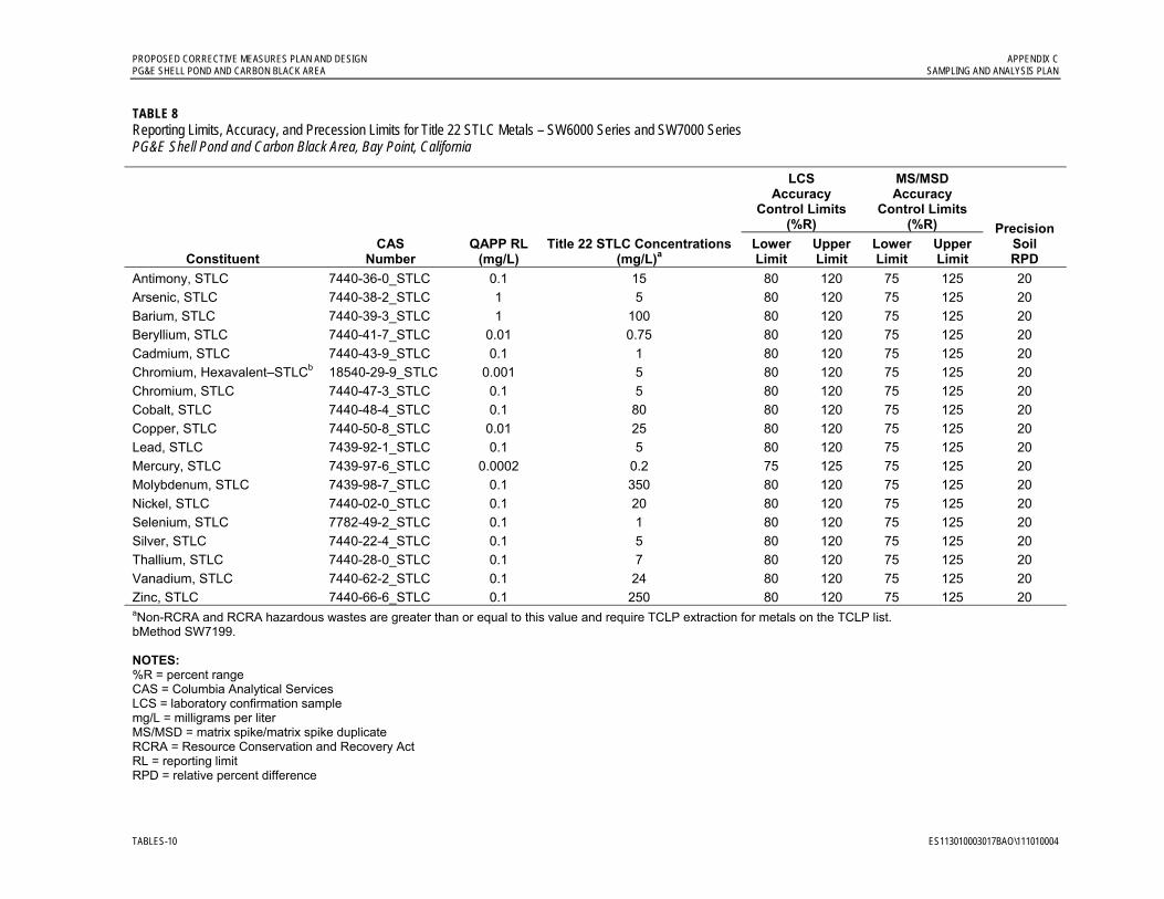
TABLE 8 Reporting Limits, Accuracy, and Precession Limits for Title 22 STLC Metals – SW6000 Series and SW7000 Series PG&E Shell Pond and Carbon Black Area, Bay Point, California
Constituent CAS
Number QAPP RL
(mg/L) Title 22 STLC Concentrations
(mg/L)a
LCS Accuracy
Control Limits (%R)
MS/MSD Accuracy
Control Limits (%R) Precision
Soil RPD
Lower Limit
Upper Limit
Lower Limit
Upper Limit
Antimony, STLC 7440-36-0_STLC 0.1 15 80 120 75 125 20
Arsenic, STLC 7440-38-2_STLC 1 5 80 120 75 125 20
Barium, STLC 7440-39-3_STLC 1 100 80 120 75 125 20
Beryllium, STLC 7440-41-7_STLC 0.01 0.75 80 120 75 125 20
Cadmium, STLC 7440-43-9_STLC 0.1 1 80 120 75 125 20
Chromium, Hexavalent–STLCb 18540-29-9_STLC 0.001 5 80 120 75 125 20
Chromium, STLC 7440-47-3_STLC 0.1 5 80 120 75 125 20
Cobalt, STLC 7440-48-4_STLC 0.1 80 80 120 75 125 20
Copper, STLC 7440-50-8_STLC 0.01 25 80 120 75 125 20
Lead, STLC 7439-92-1_STLC 0.1 5 80 120 75 125 20
Mercury, STLC 7439-97-6_STLC 0.0002 0.2 75 125 75 125 20
Molybdenum, STLC 7439-98-7_STLC 0.1 350 80 120 75 125 20
Nickel, STLC 7440-02-0_STLC 0.1 20 80 120 75 125 20
Selenium, STLC 7782-49-2_STLC 0.1 1 80 120 75 125 20
Silver, STLC 7440-22-4_STLC 0.1 5 80 120 75 125 20
Thallium, STLC 7440-28-0_STLC 0.1 7 80 120 75 125 20
Vanadium, STLC 7440-62-2_STLC 0.1 24 80 120 75 125 20
Zinc, STLC 7440-66-6_STLC 0.1 250 80 120 75 125 20 aNon-RCRA and RCRA hazardous wastes are greater than or equal to this value and require TCLP extraction for metals on the TCLP list. bMethod SW7199. NOTES: %R = percent range CAS = Columbia Analytical Services LCS = laboratory confirmation sample mg/L = milligrams per liter MS/MSD = matrix spike/matrix spike duplicate RCRA = Resource Conservation and Recovery Act RL = reporting limit RPD = relative percent difference

PROPOSED CORRECTIVE MEASURES PLAN AND DESIGN APPENDIX C PG&E SHELL POND AND CARBON BLACK AREA SAMPLING AND ANALYSIS PLAN
ES113010003017BAO\111010004 TABLES-11
TABLE 9 Reporting Limits, Accuracy, and Precession Limits for Title 22 TCLP (RCRA) Metals – SW6000 Series and SW7000 Series PG&E Shell Pond and Carbon Black Area, Bay Point, California
Constituent CAS
Number QAPP RL
(mg/L)
Title 22 TCLP Concentration
(mg/L)a
LCS Accuracy
Control Limits (%R)
MS/MSD Accuracy
Control Limits (%R) Precision
Soil RPD
Lower Limit
Upper Limit
Lower Limit
Upper Limit
Arsenic, TCLP 7440-38-2_TCLP 1 5 80 120 75 125 20
Barium, TCLP 7440-39-3_TCLP 1 100 80 120 75 125 20
Cadmium, TCLP 7440-43-9_TCLP 0.1 1 80 120 75 125 20
Chromium, TCLP 7440-47-3_TCLP 0.1 5 80 120 75 125 20
Lead, TCLP 7439-92-1_TCLP 0.1 5 80 120 75 125 20
Mercury, TCLP 7439-97-6_TCLP 0.0002 0.2 80 120 75 125 20
Selenium, TCLP 7782-49-2_TCLP 0.1 1 80 120 75 125 20
Silver, TCLP 7440-22-4_TCLP 0.1 5 80 120 75 125 20
aRCRA hazardous wastes are greater than or equal to this value. Notes: %R = percent range CAS = Columbia Analytical Services LCS = laboratory confirmation sample mg/L = milligrams per liter MS/MSD = matrix spike/matrix spike duplicate RL = reporting limit RPD = relative percent difference

PROPOSED CORRECTIVE MEASURES PLAN AND DESIGN APPENDIX C PG&E SHELL POND AND CARBON BLACK AREA SAMPLING AND ANALYSIS PLAN
TABLES-12 ES113010003017BAO\111010004
TABLE 10 Reporting Limits, Accuracy, and Precession Limits for Total Petroleum Hydrocarbons – SW8015B PG&E Shell Pond and Carbon Black Area, Bay Point, California
Constituent CAS Label
QAPP RL (mg/L)
LCS/MS/MSD Accuracy
Control Limits (%R)
Precision Water RPD
Lower Limit
Upper Limit
Motor Oil TPH-motor oil 1 50 150 30
TPH-Diesel TPH-diesel 0.5 61 143 30
Notes: %R = percent range CAS = Columbia Analytical Services LCS = laboratory confirmation sample MG/L = MILLIGRAMS PER LITER MS/MSD = matrix spike/matrix spike duplicate RL = reporting limit RPD = relative percent difference
TABLE 11
Reporting Limits, Accuracy, and Precession Limits for Total Petroleum Hydrocarbons – SW8015B PG&E Shell Pond and Carbon Black Area, Bay Point, California
Constituent CAS Label
QAPP RL (mg/kg)
LCS/MS/MSD Accuracy
Control Limits (%R)
Precision Soil RPD
Lower Limit
Upper Limit
Motor Oil TPH-motor oil 10 60 120 50
TPH-Diesel TPH-diesel 10 51 153 50
Notes: %R = percent range CAS = Columbia Analytical Services LCS = laboratory confirmation sample MG/KG = MILLIGRAMS PER KILOGRAM MS/MSD = matrix spike/matrix spike duplicate RL = reporting limit RPD = relative percent difference

PROPOSED CORRECTIVE MEASURES PLAN AND DESIGN APPENDIX C PG&E SHELL POND AND CARBON BLACK AREA SAMPLING AND ANALYSIS PLAN
ES113010003017BAO\111010004 TABLES-13
TABLE 12 Reporting Limits, Accuracy, and Precession Limits for Volatile Organic Compounds – SW8260B PG&E Shell Pond and Carbon Black Area, Bay Point, California
Constituent CAS
Number QAPP RL
(µg/L)
LCS/MS/MSD Accuracy Control
Limits (%R) Precision
Water RPD
Lower Limit
Upper Limit
1,1,1,2-Tetrachloroethane 630-20-6 0.5 81 129 20
1,1,1-Trichloroethane (TCA) 71-55-6 1 67 132 20
1,1,2,2-Tetrachloroethane 79-34-5 0.5 63 128 20
1,1,2-Trichloroethane 79-00-5 1 75 125 20
1,1,2-Trichlorotrifluoroethane (Freon 113) 76-13-1 1 75 125 20
1,1-Dichloroethane 75-34-3 1 69 133 20
1,1-Dichloroethene or 1,1-Dichloroethylene (1,1-DCE)
75-35-4 1 68 130 20
1,1-Dichloropropene 563-58-6 1 73 132 20
1,2,3-Trichlorobenzene 87-61-6 1 67 137 20
1,2,3-Trichloropropane 96-18-4 1 73 124 20
1,2,4-Trichlorobenzene 120-82-1 1 66 134 20
1,2,4-Trimethylbenzene 95-63-6 1 74 132 20
1,2-Dibromo-3-Chloropropane 96-12-8 2 50 132 20
1,2-Dibromoethane (EDB) 106-93-4 1 80 121 20
1,2-Dichlorobenzene 95-50-1 1 71 122 20
1,2-Dichloroethane (EDC) 107-06-2 0.5 69 132 20
1,2-Dichloropropane 78-87-5 1 75 125 20
1,3,5-Trimethylbenzene 108-67-8 1 74 131 20
1,3-Dichlorobenzene 541-73-1 1 75 124 20
1,3-Dichloropropane 142-28-9 1 73 126 20
1,4-Dichlorobenzene 106-46-7 0.5 74 123 20
2,2-Dichloropropane 594-20-7 1 69 137 20
2-Butanone (MEK) 78-93-3 10 49 136 20
2-Chlorotoluene 95-49-8 1 73 126 20
4-Chlorotoluene 106-43-4 1 74 128 20
4-Isopropyltoluene 99-87-6 1 73 130 20
4-Methyl-2-Pentanone 108-10-1 10 58 134 20
Acetone 67-64-1 10 40 135 20
Acrolein 107-02-8 20 75 125 20
Acrylonitrile 107-13-1 20 75 125 20
Benzene 71-43-2 0.4 81 122 20
Bromobenzene 108-86-1 1 76 124 20
Bromochloromethane 74-97-5 1 65 129 20
Bromodichloromethane 75-27-4 0.5 76 121 20
Bromoform 75-25-2 1 69 128 20
Bromomethane 74-83-9 3 53 141 20
Carbon Disulfide 75-15-0 1 75 125 20
Carbon Tetrachloride 56-23-5 1 66 138 20
Chlorobenzene 108-90-7 0.5 81 122 20

PROPOSED CORRECTIVE MEASURES PLAN AND DESIGN APPENDIX C PG&E SHELL POND AND CARBON BLACK AREA SAMPLING AND ANALYSIS PLAN
TABLES-14 ES113010003017BAO\111010004
TABLE 12 Reporting Limits, Accuracy, and Precession Limits for Volatile Organic Compounds – SW8260B PG&E Shell Pond and Carbon Black Area, Bay Point, California
Constituent CAS
Number QAPP RL
(µg/L)
LCS/MS/MSD Accuracy Control
Limits (%R) Precision
Water RPD
Lower Limit
Upper Limit
Chloroethane 75-00-3 1 58 133 20
Chloroform 67-66-3 1 69 128 20
Chloromethane 74-87-3 1 56 131 20
cis-1,2-Dichloroethene or cis-1,2-Dichloroethylene
156-59-2 1 72 126 20
cis-1,3-Dichloropropene 10061-01-5 0.5 69 131 20
Dibromochloromethane 124-48-1 0.5 66 133 20
Dibromomethane 74-95-3 1 76 125 20
Dichlorodifluoromethane (Freon 12) 75-71-8 1 53 153 20
Ethylbenzene 100-41-4 1 73 127 20
Hexachlorobutadiene 87-68-3 0.6 67 131 20
Isopropylbenzene (Cumene) 98-82-8 1 75 127 20
Methylene chloride 75-09-2 1 63 137 20
Naphthalene 91-20-3 1 54 138 20
n-Butylbenzene 104-51-8 1 69 137 20
n-Propylbenzene 103-65-1 1 72 129 20
sec-Butylbenzene 135-98-8 1 72 127 20
Styrene 100-42-5 1 65 134 20
tert-Butyl Methyl Ether (MTBE) 1634-04-4 5 65 123 20
tert-Butylbenzene 98-06-6 1 70 129 20
Tetrachloroethene or Tetrachloroethylene (PCE)
127-18-4 1 66 128 20
Toluene 108-88-3 1 77 122 20
trans-1,2-Dichloroethene or trans-1,2-Dichloroethylene
156-60-5 1 63 137 20
trans-1,3-Dichloropropene 10061-02-6 1 59 135 20
Trichloroethene or Trichloroethylene (TCE)
79-01-6 1 70 127 20
Trichlorofluoromethane (Freon 11) 75-69-4 1 57 129 20
Vinyl Chloride 75-01-4 1 50 134 20
Xylenes, Total 1330-20-7 2 75 125 20
m -Xylene 108-38-3 2 76 128 20
o-Xylene 95-47-6 1 80 121 20
p-Xylene 106-42-3 1 76 128 20
Notes: %R = percent range µG/L = MICROGRAMS PER LITER CAS = Columbia Analytical Services LCS = laboratory confirmation sample MS/MSD = matrix spike/matrix spike duplicate RL = reporting limit RPD = relative percent difference

PROPOSED CORRECTIVE MEASURES PLAN AND DESIGN APPENDIX C PG&E SHELL POND AND CARBON BLACK AREA SAMPLING AND ANALYSIS PLAN
ES113010003017BAO\111010004 TABLES-15
TABLE 13 Reporting Limits, Accuracy, and Precession Limits for Volatile Organic Compounds – SW8260B PG&E Shell Pond and Carbon Black Area, Bay Point, California
Constituent CAS
Number QAPP RL
(µg/kg)
LCS/MS/MSD Accuracy
Control Limits (%R) Precision
Soil RPD
Lower Limit
Upper Limit
1,1,1,2-Tetrachloroethane 630-20-6 5 74 125 30
1,1,1-Trichloroethane (TCA) 71-55-6 5 68 130 30
1,1,2,2-Tetrachloroethane 79-34-5 5 59 140 30
1,1,2-Trichloroethane 79-00-5 5 62 127 30
1,1,2-Trichlorotrifluoroethane (Freon 113) 76-13-1 5 65 135 30
1,1-Dichloroethane 75-34-3 5 73 125 30
1,1-Dichloroethylene or 1,1-Dichloroethene (1,1-DCE) 75-35-4 5 65 136 30
1,1-Dichloropropene 563-58-6 5 70 135 30
1,2,3-Trichlorobenzene 87-61-6 5 62 133 30
1,2,3-Trichloropropane 96-18-4 5 63 130 30
1,2,4-Trichlorobenzene 120-82-1 5 65 131 30
1,2,4-Trimethylbenzene 95-63-6 5 65 135 30
1,2-Dibromo-3-chloropropane 96-12-8 5 49 135 30
1,2-Dibromoethane (EDB) 106-93-4 5 70 124 30
1,2-Dichlorobenzene 95-50-1 5 74 120 30
1,2-Dichloroethane (EDC) 107-06-2 5 72 137 30
1,2-Dichloropropane 78-87-5 5 71 120 30
1,3,5-Trimethylbenzene 108-67-8 5 65 133 30
1,3-Dichlorobenzene 541-73-1 5 72 124 30
1,3-Dichloropropane 142-28-9 5 76 123 30
1,4-Dichlorobenzene 106-46-7 5 72 125 30
2,2-Dichloropropane 594-20-7 5 67 134 30
2-Butanone (MEK) 78-93-3 50 40 135 30
2-Chlorotoluene 95-49-8 5 69 128 30
4-Chlorotoluene 106-43-4 5 73 126 30
4-Isopropyltoluene 99-87-6 6 75 133 30
4-Methyl-2-pentanone 108-10-1 50 65 135 30
Acetone 67-64-1 50 40 141 30
Acrolein 107-02-8 100 65 135 30
Acrylonitrile 107-13-1 50 65 135 30
Benzene 71-43-2 5 73 126 30
Bromobenzene 108-86-1 5 66 121 30
Bromochloromethane 74-97-5 5 71 127 30
Bromodichloromethane 75-27-4 5 72 128 30
Bromoform 75-25-2 6 66 137 30
Bromomethane 74-83-9 5 45 141 30

PROPOSED CORRECTIVE MEASURES PLAN AND DESIGN APPENDIX C PG&E SHELL POND AND CARBON BLACK AREA SAMPLING AND ANALYSIS PLAN
TABLES-16 ES113010003017BAO\111010004
TABLE 13 Reporting Limits, Accuracy, and Precession Limits for Volatile Organic Compounds – SW8260B PG&E Shell Pond and Carbon Black Area, Bay Point, California
Constituent CAS
Number QAPP RL
(µg/kg)
LCS/MS/MSD Accuracy
Control Limits (%R) Precision
Soil RPD
Lower Limit
Upper Limit
Carbon disulfide 75-15-0 5 65 135 30
Carbon tetrachloride 56-23-5 5 67 133 30
Chlorobenzene 108-90-7 5 75 123 30
Chloroethane 75-00-3 5 41 141 30
Chloroform 67-66-3 2 72 124 30
Chloromethane 74-87-3 5 51 129 30
cis-1,2-Dichloroethene or cis-1,2-Dichloroethylene 156-59-2 5 67 125 30
cis-1,3-Dichloropropene 10061-01-5 5 72 126 30
Dibromochloromethane 124-48-1 5 66 130 30
Dibromomethane 74-95-3 5 73 128 30
Dichlorodifluoromethane 75-71-8 5 34 136 30
Ethylbenzene 100-41-4 5 74 127 30
Hexachlorobutadiene 87-68-3 5 53 142 30
Isopropylbenzene (Cumene) 98-82-8 5 77 129 30
Methylene Chloride 75-09-2 5 63 137 30
Naphthalene 91-20-3 5 51 135 30
n-Butylbenzene 104-51-8 5 65 138 30
n-Propylbenzene 103-65-1 5 63 135 30
sec-Butylbenzene 135-98-8 5 63 132 30
Styrene 100-42-5 5 74 128 30
tert-Butyl Methyl Ether (MTBE) 1634-04-4 20 50 135 30
tert-Butylbenzene 98-06-6 5 65 132 30
Tetrachloroethene or Tetrachloroethylene (PCE) 127-18-4 5 67 139 30
Toluene 108-88-3 5 71 127 30
trans-1,2-Dichloroethene or trans-1,2-Dichloroethylene 156-60-5 5 66 134 30
trans-1,3-Dichloropropene 10061-02-6 5 65 127 30
Trichloroethene or Trichloroethylene (TCE) 79-01-6 5 77 124 30
Trichlorofluoromethane (Freon 11) 75-69-4 5 49 139 30
Vinyl Chloride 75-01-4 5 58 126 30
Xylenes, Total 1330-20-7 15 65 125 50
m-Xylene 108-38-3 10 79 126 30
p-Xylene 106-42-3 10 79 126 30
o-Xylene 95-47-6 5 77 125 30

PROPOSED CORRECTIVE MEASURES PLAN AND DESIGN APPENDIX C PG&E SHELL POND AND CARBON BLACK AREA SAMPLING AND ANALYSIS PLAN
ES113010003017BAO\111010004 TABLES-17
TABLE 13 Reporting Limits, Accuracy, and Precession Limits for Volatile Organic Compounds – SW8260B PG&E Shell Pond and Carbon Black Area, Bay Point, California
Constituent CAS
Number QAPP RL
(µg/kg)
LCS/MS/MSD Accuracy
Control Limits (%R) Precision
Soil RPD
Lower Limit
Upper Limit
Notes: %R = percent range µg/kg = micrograms per kilogram CAS = Columbia Analytical Services LCS = laboratory confirmation sample MS/MSD = matrix spike/matrix spike duplicate RL = reporting limit RPD = relative percent difference

PROPOSED CORRECTIVE MEASURES PLAN AND DESIGN APPENDIX C PG&E SHELL POND AND CARBON BLACK AREA SAMPLING AND ANALYSIS PLAN
TABLES-18 ES113010003017BAO\111010004
TABLE 14 Maximum Concentrations for Title 22 – Organic Compounds – SW8000 Series PG&E Shell Pond and Carbon Black Area, Bay Point, California
Constituent CAS
Number
TTLC Concentration
Maximum (mg/kg)
STLC Concentration
Maximum (mg/L)
TCLP Concentration
Maximum (mg/L)
SW8260B
Benzene 71-43-2 0.5
Carbon tetrachloride 56-23-5 0.5
Chlorobenzene 108-90-7 100
Chloroform 67-66-3 6
o-Cresol (2-Methylphenol) 95-48-7 200a
m-Cresol 108-39-4 200a
p-Cresol (4-Methylphenol) 106-44-5 200a
Total Cresols 200a
1,4-Dichlorobenzene 106-46-7 7.5
1,2-Dichloroethane (EDC) 107-06-2 0.5
1,1-Dichloroethylene 75-35-4 0.7
Hexachlorobutadiene 87-68-3 0.5
Tetrachloroethylene (PCE) 127-18-4 2,040 204 0.7
Vinyl chloride 75-01-4 0.2
Trichloroethylene (TCE) 79-01-6 0.5
2-Butanone (MEK) 78-93-3 200 aCombine concentration of cresol in any form. Notes: CAS = Columbia Analytical Services mg/kg = milligrams per kilogram mg/L = milligrams per liter

PROPOSED CORRECTIVE MEASURES PLAN AND DESIGN APPENDIX C PG&E SHELL POND AND CARBON BLACK AREA SAMPLING AND ANALYSIS PLAN
ES113010003017BAO\111010004 TABLES-19
TABLE 15 Reporting Limits, Accuracy, and Precession Limits for Polycyclic Aromatic Hydrocarbon – SW8270SIM PG&E Shell Pond and Carbon Black Area, Bay Point, California
Constituent CAS
Number QAPP RL
(µg/L)
LCS/MS/MSD Accuracy
Control Limits (%R)
Precision WaterRPD
Lower Limit
Upper Limit
1-methylnaphthalene 90-12-0 0.2 35 131 30
2-methylnaphthalene 91-57-6 0.2 36 121 30
Acenaphthene 83-32-9 0.2 39 125 30
Acenaphthylene 208-96-8 0.2 43 140 30
Anthracene 120-12-7 0.2 41 132 30
Benzo (a) anthracene 56-55-3 0.2 58 141 30
Benzo (a) pyrene 50-32-8 0.2 31 142 30
Benzo (b) fluoranthene 205-99-2 0.2 42 156 30
Benzo (g,h,i) perylene 191-24-2 0.2 12 171 30
Benzo (k) fluoranthene 207-08-9 0.2 49 165 30
Chrysene 218-01-9 0.2 51 155 30
Dibenzo (a,h) anthracene 53-70-3 0.2 28 153 30
Fluoranthene 206-44-0 0.2 47 158 30
Fluorene 86-73-7 0.2 40 140 30
Indeno (1,2,3-c,d) pyrene 193-39-5 0.2 20 167 30
Naphthalene 91-20-3 0.2 39 125 30
Phenanthrene 85-01-8 0.2 46 144 30
Pyrene 129-00-0 0.2 39 158 30
Notes: %R = percent range µG/L = MICROGRAMS PER LITER CAS = Columbia Analytical Services LCS = laboratory confirmation sample MS/MSD = matrix spike/matrix spike duplicate RL = reporting limit RPD = relative percent difference

PROPOSED CORRECTIVE MEASURES PLAN AND DESIGN APPENDIX C PG&E SHELL POND AND CARBON BLACK AREA SAMPLING AND ANALYSIS PLAN
TABLES-20 ES113010003017BAO\111010004
TABLE 16
Reporting Limits, Accuracy, and Precession Limits for Polycyclic Aromatic Hydrocarbon – SW8270SIM PG&E Shell Pond and Carbon Black Area, Bay Point, California
Constituent CAS
Number QAPP RL
(µg/kg)
LCS/MS/MSD Accuracy Control Limits
(%R) Precision Soil RPD
Lower Limit
Upper Limit
1-methylnaphthalene 90-12-0 5 30 111 30
2-methylnaphthalene 91-57-6 5 30 111 30
Acenaphthene 83-32-9 5 28 110 30
Acenaphthylene 208-96-8 5 23 126 30
Anthracene 120-12-7 5 28 136 30
Benzo (a) anthracene 56-55-3 5 31 146 30
Benzo (a) pyrene 50-32-8 5 28 128 30
Benzo (b) fluoranthene 205-99-2 5 30 139 30
Benzo (g,h,i) perylene 191-24-2 5 21 149 30
Benzo (k) fluoranthene 207-08-9 5 42 129 30
Chrysene 218-01-9 5 39 134 30
Dibenzo (a,h) anthracene 53-70-3 5 30 138 30
Fluoranthene 206-44-0 5 30 142 30
Fluorene 86-73-7 5 27 116 30
Indeno (1,2,3-c,d) pyrene 193-39-5 5 17 164 30
Naphthalene 91-20-3 5 29 106 30
Phenanthrene 85-01-8 5 32 127 30
Pyrene 129-00-0 5 28 130 30
Notes: %R = percent range µG/KG = MICROGRAMS PER KILOGRAM CAS = Columbia Analytical Services LCS = laboratory confirmation sample MS/MSD = matrix spike/matrix spike duplicate RL = reporting limit RPD = relative percent difference

PROPOSED CORRECTIVE MEASURES PLAN AND DESIGN APPENDIX C PG&E SHELL POND AND CARBON BLACK AREA SAMPLING AND ANALYSIS PLAN
ES113010003017BAO\111010004 TABLES-21
TABLE 17 Calibration and QC Requirements for General Chemistry and Other Parametersa PG&E Shell Pond and Carbon Black Area, Bay Point, California
QC Check Frequency Criteria Corrective Action
Multipoint ICAL (a blank and at least five standards); does not apply to titrimetric method
Before initial sample analysis, every 24 hours, when modifications are made to the analytical system, or when continuing calibration verification fails.
Correlation coefficient of linear regression is 0.995.
Correct the problem and repeat the ICAL.
Second-source Calibration Verification
Immediately following each ICAL.
Analytes within 15% of expected value (10% for SW9056/EPA300.0).
Correct the problem and repeat ICAL.
Calibration Blank; does not apply to titrimetric method
After every second-source or continuing calibration verification analysis.
No analytes detected at or above the RL.
Correct the problem, then reanalyze previous 10 samples.
Continuing Calibration Verification
After every 10 samples and at the end of the analysis sequence.
Within 15% of expected value (10% for SW9056/EP300.0).
Recalibrate and reanalyze all samples since the last acceptable continuing calibration verification.
Method Blank At least one per analytical batch.
No analytes detected at or above the RL.
Correct the problem, re-prepare, and reanalyze all associated samples.
MS/MSD One set per 20 project-specific samples. MSD is optional if a laboratory sample duplicate is performed.
All analytes within limits specified in Table 2.
None.
Laboratory Sample Duplicate
Once per analytical batch if MSD not performed.
Concentration of reported analytes are >5 times the RL in either sample and RPD >20%.
One sample result <RL and a difference of ±2 times the RL.
None.
LCS At least one per analytical batch.
All analytes within limits specified in Table 2.
Correct the problem, re-prepare, and reanalyze the LCS and all samples in the analytical batch.
ICAL Verification (ICCS) (EPA314.0 only)
Daily, before sample analysis or when eluent is changed.
Instrument response within 25% of expected value using a standard at or below the RL.
Correct problem then repeat ICAL.
Pretreated Laboratory Reagent Blank (EPA314.0 only)
Required in any analytical batch which includes samples that have been pretreated to reduce the common anion levels.
Perchlorate must be ½ RL. Correct problem, re-prepare, and analyze method blank and all samples processed with the contaminated blank.

PROPOSED CORRECTIVE MEASURES PLAN AND DESIGN APPENDIX C PG&E SHELL POND AND CARBON BLACK AREA SAMPLING AND ANALYSIS PLAN
TABLES-22 ES113010003017BAO\111010004
TABLE 17 Calibration and QC Requirements for General Chemistry and Other Parametersa PG&E Shell Pond and Carbon Black Area, Bay Point, California
QC Check Frequency Criteria Corrective Action
Low-level MDL Check Standard (EPA314.0 only)
Weekly and with ICAL. Must meet QC acceptance criteria, 50 to 150% of its true concentration.
Reanalyze low-level MDL check standard, if still out of criteria, repeat ICAL.
aUnless calibration and QC requirements are specified for an individual method. Notes: ICAL = initial calibration ICCS = initial calibration check standard MDL = method detection limit MS/MSD = matrix spike/matrix spike duplicate LCS = laboratory confirmation sample RL = reporting limit RPD = relative percent difference

PROPOSED CORRECTIVE MEASURES PLAN AND DESIGN APPENDIX C PG&E SHELL POND AND CARBON BLACK AREA SAMPLING AND ANALYSIS PLAN
ES113010003017BAO\111010004 TABLES-23
TABLE 18 Calibration and QC Requirements for Metals – SW6010B and EPA200.7 PG&E Shell Pond and Carbon Black Area, Bay Point, California
QC Check Frequency Criteria Corrective Action
ICAL (a blank and at least one standard)
Before sample analysis, every 24 hours, when modifications are made to the system, or when continuing calibration verification fails.
If more than one standard is used, correlation coefficient must be >0.995.
Not applicable.
Second-source Calibration Verification
Immediately following each ICAL.
All analytes within 10% of expected value for SW6010B and within 5% of expected value for EPA200.7.
Correct problem and repeat ICAL.
Calibration Blank After every second-source or continuing calibration verification analysis.
No analytes detected at or above the RL.
Correct the problem and reanalyze previous 10 samples.
Continuing Calibration Verification
After every 10 samples and at the end of the analysis sequence.
All analytes within 10% of expected value for SW6010B and within 10% of expected value for EPA200.7.
Recalibrate and reanalyze all samples since the last acceptable continuing calibration verification.
Method Blank At least one per analytical batch.
No analytes detected at or above the RL.
Correct the problem, re-prepare, and reanalyze all associated samples.
Interference Check Standard
At the start and end of each analytical sequence or twice during an 8-hour period, whichever is more frequent.
All analytes within 20% of expected value.
Correct the problem, recalibrate, and reanalyze ICS and all affected samples.
MS/MSD One set per 20 project-specific samples. MSD is optional if a laboratory sample duplicate is performed.
All analytes within limits specified in Tables 4 through 8.
None.
Laboratory Sample Duplicate
Once per analytical batch if MSD not performed.
Concentration of reported analytes are >5 times the RL in either sample and RPD >20%. One sample result <RL and a difference of ±2 times the RL.
None.
LCS At least one per analytical batch.
All analytes within limits specified in Tables 4 through 8.
Correct the problem, re-prepare and reanalyze the LCS and all samples in the analytical batch.
Dilution Test Each new sample matrix. Result from 1:5 dilution must be within 10% of the undiluted sample result (applies only if undiluted sample result is at least 25 times the RL).
Perform post-digestion spike addition.
Linear Range Calibration Check Standard
Once per quarter. All analytes within +10% of expected value.
Correct problem and reanalyze or reset linear range.
Post-digestion Spike Addition
When dilution test fails. Recovery within 75 to 125% of expected value.
None.

PROPOSED CORRECTIVE MEASURES PLAN AND DESIGN APPENDIX C PG&E SHELL POND AND CARBON BLACK AREA SAMPLING AND ANALYSIS PLAN
TABLES-24 ES113010003017BAO\111010004
TABLE 19 Calibration and QC Requirements for Metals – SW6020 and EPA200.8 PG&E Shell Pond and Carbon Black Area, Bay Point, California
QC Check Frequency Criteria Corrective Action
ICAL (a blank and at least one standard)
Before initial sample analysis, every 24 hours, when modifications are made to the analytical system, or when continuing calibration verification fails.
Not applicable. Not applicable.
Second-source Calibration Verification
Immediately following each ICAL.
All analytes within 10% of expected value.
Correct problem and repeat ICAL.
Calibration Blank After every Second-source or Continuing calibration verification analysis.
No analytes detected at or above the RL.
Correct the problem and reanalyze previous 10 samples.
Continuing Calibration Verification
After every 10 samples and at the end of the analysis sequence.
All analytes within 10% of expected value.
Recalibrate and reanalyze all samples since the last acceptable continuing calibration verification.
Method Blank At least one per analytical batch.
No analytes detected at or above the RL.
Correct the problem, re-prepare, and reanalyze all associated samples.
Interference Check Standard
At the start and end of each analytical sequence or twice during an 8-hour period, whichever is more frequent.
All analytes within 20% of expected value.
Correct the problem, recalibrate and reanalyze ICS and all affected samples.
MS/MSD One set per 20 project-specific samples. MSD is optional if a laboratory sample duplicate is performed.
All analytes within limits specified in Tables 4 through 8.
None.
Laboratory Sample Duplicate
Once per analytical batch if MSD not performed.
Concentration of reported analytes are >5 times the RL in either sample and RPD >20%. One sample result <RL and a difference of ±2 times the RL.
None.
LCS At least one per analytical batch.
All analytes within limits specified in Tables 4 through 8.
Correct the problem, re-prepare, and reanalyze the LCS and all samples in the analytical batch.
Dilution Test Each new sample matrix. Result from 1:5 dilution must be within 10% of the undiluted sample result (applies only if undiluted sample result is at least 25 times the RL).
Perform post-digestion spike addition.
Post-digestion Spike Addition
When dilution test fails. Recovery within 75 to 125% of expected value.
None.
Notes: ICAL = initial calibration ICS = Interference Check Standard LCS = laboratory confirmation sample MS/MSD = matrix spike/matrix spike duplicate RL = reporting limit RPD = relative percent difference

PROPOSED CORRECTIVE MEASURES PLAN AND DESIGN APPENDIX C PG&E SHELL POND AND CARBON BLACK AREA SAMPLING AND ANALYSIS PLAN
ES113010003017BAO\111010004 TABLES-25
TABLE 20 Calibration and QC Requirements for Metals – SW7000 Series and EPA245.1 PG&E Shell Pond and Carbon Black Area, Bay Point, California
QC Check Frequency Criteria Corrective Action
Multipoint ICAL (a blank and at least five standards)
Before initial sample analysis, every 24 hours, when modifications are made to the analytical system, or when continuing calibration verification fails.
Correlation coefficient of linear regression is 0.995.
Correct the problem and repeat the ICAL.
Second-source Calibration Verification
Immediately following each ICAL.
All analytes within 20% of expected value.
Correct the problem and repeat ICAL.
Calibration Blank After every second-source or continuing calibration verification analysis.
No analytes detected at or above the RL.
Correct the problem, then reanalyze previous 10 samples.
Continuing Calibration Verification
After every 10 samples and at the end of the analysis sequence.
All analytes within 20% of expected value.
Recalibrate and reanalyze all samples since the last accept-able continuing calibration verification.
Method Blank At least one per analytical batch.
No analytes detected at or above the RL.
Correct the problem, re-prepare, and reanalyze all associated samples.
MS/MSD One set per 20 project-specific samples. MSD is optional if a laboratory sample duplicate is performed.
All analytes within limits specified in accuracy and precision table.
None.
Laboratory Sample Duplicate
Once per analytical batch if MSD not performed.
Concentration of reported analytes are >5 times the RL in either sample and RPD >20%. One sample result <RL and a difference of ±2 times the RL.
None.
LCS At least one per analytical batch.
All analytes within limits specified Tables 4 through 8.
Correct the problem, re-prepare, and reanalyze the LCS and all samples in the analytical batch.
Dilution Test Each new sample matrix. Result from 1:5 dilution must be within 10% of the undiluted sample result (applies only if undiluted sample result is at least 25 times the RL).
Perform recovery test.
Recovery Test When dilution test fails. Recovery within 85 to 115% of expected value.
Analyze all samples by MSA.
Notes: ICAL = initial calibration MS/MSD = matrix spike/matrix spike duplicate MSA = method of standard addition LCS = laboratory confirmation sample RL = reporting limit RPD = relative percent difference

PROPOSED CORRECTIVE MEASURES PLAN AND DESIGN APPENDIX C PG&E SHELL POND AND CARBON BLACK AREA SAMPLING AND ANALYSIS PLAN
TABLES-26 ES113010003017BAO\111010004
TABLE 21 Soil Preparation Method SW3060A for Method SW7199 PG&E Shell Pond and Carbon Black Area, Bay Point, California
QC Check Frequency Criteria Corrective Action
2.5 grams sample to a final volume of 100 ml must be used for each sample
Each sample in the preparation batch.
Follow method preparation for all samples, method blank, and QC samples.
Method Blank One per preparation batch. No analytes detected at or above the RL.
Correct the problem, re-prepare, and reanalyze all associated samples.
LCS One per preparation batch. Spike at concentration specified in method. Recovery range 80 to 120%.
Correct the problem, re-prepare, and reanalyze the LCS and all samples in the analytical batch.
Soluble Matrix Spike One per preparation batch. Spike at concentration specified in method. Recovery range 75 to 125%.
None.
Insoluble Matrix Spike One per preparation batch. Spike at concentration specified in method. Recovery range 75 to 125%.
None.
Post-digestion Spike One per preparation batch. Spike at concentration specified in method. Recovery range 85 to 115%.
None.
Notes: LCS = laboratory confirmation sample ml = milliliter RL = reporting limit

PROPOSED CORRECTIVE MEASURES PLAN AND DESIGN APPENDIX C PG&E SHELL POND AND CARBON BLACK AREA SAMPLING AND ANALYSIS PLAN
ES113010003017BAO\111010004 TABLES-27
TABLE 22 Calibration and QC Requirements for TPHs – SW8015B PG&E Shell Pond, and Carbon Black Area, Bay Point, California
QC Check Frequency Criteria Corrective Action
Multipoint ICAL (minimum 5 points)
Prior to sample analysis, or when calibration verification fails.
If the %RSD is 20%, the average RRF may be used for quantitation; otherwise use calibration curve with coefficient of correlation or determination 0.99.
Correct the problem and repeat the ICAL.
Continuing Calibration Verification
At the start of each analytical sequence and after every 10 samples, and at the end of the sequence.
Analytes within 15% of expected value.
Correct the problem, recalibrate, and reanalyze all samples since the last acceptable continuing calibration verification.
Method Blank At least one per analytical batch.
No analytes detected at or above the RL.
Correct the problem, re-prepare, and reanalyze all associated samples.
Surrogate Spike Every standard, sample, method blank, MS/MSD, and LCS.
All surrogates in samples, method blank, MS/MSD, and LCS within limits specified in Tables 9 and 10.
Correct the problem and reanalyze (re-prepare if necessary).
MS/MSD One set per 20 samples. Full target list spike required within limits specified in Tables 9 and 10.
None.
LCS At least one per analytical batch.
Full target list spike required within limits specified in Tables 9 and 10.
Correct the problem, re-prepare, and reanalyze the LCS and all samples in the analytical batch.
Notes: ICAL = initial calibration LCS = laboratory confirmation sample MS/MSD = matrix spike/matrix spike duplicate RRF = relative response factor RSD = relative standard deviation

PROPOSED CORRECTIVE MEASURES PLAN AND DESIGN APPENDIX C PG&E SHELL POND AND CARBON BLACK AREA SAMPLING AND ANALYSIS PLAN
TABLES-28 ES113010003017BAO\111010004
TABLE 23 Calibration and QC Requirements for VOCs – SW8260B PG&E Shell Pond and Carbon Black Area, Bay Point, California
QC Check Frequency Criteria Corrective Action
BFB Tuning Prior to ICAL and calibration verification (every 12 hours).
Refer to criteria listed in the method. Retune instrument and verify.
Multipoint ICAL (minimum 5 points)
Prior to sample analysis, or when calibration verification fails.
SPCCs average RRF 0.30a and %RSD for RRFs for CCCs 30% and one of the following options:
Correct the problem and repeat the ICAL.
Option 1
Linear – RSD for each analyte <15%. Use of the mean %RSD for all analytes 15% may not be used.
Option 2
Linear – least squares regression r 0.995.
Option 3
Nonlinear – coefficient of determination ≥0.99 (6 standards to used for a second order; 7 standards to be used for a third order).
Second-source Calibration Verification
Once for each multipoint ICAL.
All analytes within 25% of expected value.
Correct the problem and repeat ICAL.
Continuing Calibration Verification
At the start of each analytical sequence and every 12 hours thereafter.
SPCCs average RF 0.30c and %D for RFs for CCCs 20%.
All other analytes within ±20% of expected value.
Correct the problem, recalibrate, and reanalyze all samples since the last acceptable continuing calibration verification.
Retention Time Window Calculated for Each Analyte
Each analyte. Relative retention time of each analyte within ±0.06 relative retention time units of the ICAL.
Not applicable (used for identification of analyte).
Internal Standards Each sample and QC sample, method blank, MS/MSD and LCS.
Continuing calibration verification retention time within 30 seconds from retention time of the ICAL midpoint standard.
Sample retention time within 30 seconds from retention time of the daily continuing calibration verification.
Continuing calibration verification EICP area within –50% to +100% of the internal standard responses in the ICAL midpoint standard.
Sample EICP area within –50% to +100% of the daily continuing calibration verification.
Inspect mass spectrometer and gas chromatography for malfunctions; reanalyze all affected samples.
Method Blank At least one per analytical batch.
No analytes detected at or above the RL.
Correct the problem, re-prepare, and reanalyze

PROPOSED CORRECTIVE MEASURES PLAN AND DESIGN APPENDIX C PG&E SHELL POND AND CARBON BLACK AREA SAMPLING AND ANALYSIS PLAN
ES113010003017BAO\111010004 TABLES-29
TABLE 23 Calibration and QC Requirements for VOCs – SW8260B PG&E Shell Pond and Carbon Black Area, Bay Point, California
QC Check Frequency Criteria Corrective Action
all associated samples.
Surrogate Spike Every standard, sample, method blank, MS/MSD and LCS.
All surrogates in samples, method blank and LCS within limits specified in Table 5-15 of the program QAPP.
Correct the problem and reanalyze (re-prepare if necessary).
MS/MSD One set per 20 project-specific samples.
Full target list spike required within limits specified in Tables 12 and 13.
None.
LCS At least one per analytical batch.
Full target list spike required within limits specified in Tables 12 and 13.
Correct the problem, re-prepare, and reanalyze the LCS and all samples in the analytical batch.
aSPCC average RRF 0.10 for bromoform, chloromethane, and 1,1-dichloroethane. Notes: BFB = bromofluorobenzene CCC = calibration check compounds EICP = extracted ion current profile SPCC ICAL = initial calibration LCS = laboratory confirmation sample MS/MSD = matrix spike/matrix spike duplicate RF = response factor RL = reporting limit RRF= relative response factor RSD = relative standard deviation SPCC = System Performance Check Compounds

PROPOSED CORRECTIVE MEASURES PLAN AND DESIGN APPENDIX C PG&E SHELL POND AND CARBON BLACK AREA SAMPLING AND ANALYSIS PLAN
TABLES-30 ES113010003017BAO\111010004
TABLE 24 Calibration and QC Requirements for Polycyclic Aromatic Hydrocarbons – SW8270C SIM PG&E Shell Pond and Carbon Black Area, Bay Point, California
QC Check Frequency Criteria Corrective Action
DFTPP Tuning Prior to ICAL and calibration verification (every 12 hours).
Refer to criteria listed in the method.
Retune instrument and verify.
Multipoint ICAL (minimum 5 points)
Prior to sample analysis, or when calibration verification fails.
SPCCs average RF 0.050 and %RSD for RFs for CCCs 30% and one of the following options:
Correct the problem and repeat the ICAL.
Option 1
RSD for each analyte <15%.
Option 2
Least squares regression r 0.990.
Option 3
Nonlinear – Coefficient of Determination ≥0.99 (6 standards to used for a second order; 7 standards to be used for a third order).
Second-source Calibration Verification
Once for each multipoint ICAL.
All analytes within 30% of expected value.
Correct the problem and repeat ICAL.
Continuing Calibration Verification
At the start of each analytical sequence and every 12 hours thereafter.
All analytes within ±20% of expected.
Correct the problem, recalibrate, and reanalyze all samples since the last accept-able continuing calibration verification.
Retention Time Window Calculated for Each Analyte
Each analyte. Relative retention time of each analyte within +0.06 relative retention time units of the ICAL.
Not applicable (used for identification of analyte).

PROPOSED CORRECTIVE MEASURES PLAN AND DESIGN APPENDIX C PG&E SHELL POND AND CARBON BLACK AREA SAMPLING AND ANALYSIS PLAN
ES113010003017BAO\111010004 TABLES-31
TABLE 24 Calibration and QC Requirements for Polycyclic Aromatic Hydrocarbons – SW8270C SIM PG&E Shell Pond and Carbon Black Area, Bay Point, California
QC Check Frequency Criteria Corrective Action
Internal Standards Each sample and QC sample, method blank, MS/MSD, and LCS.
Continuing calibration verification retention time within 30 seconds from retention time of the ICAL midpoint standard.
Sample retention time within 30 seconds from retention time of the daily continuing calibration verification.
Continuing calibration verification EICP area within -50% to +100% of the internal standard responses in the ICAL midpoint standard.
Sample EICP area within -50% to +100% of the daily continuing calibration verification.
Inspect mass spectrometer and gas chromatography for malfunctions; reanalyze all affected samples.
Method Blank At least one per analytical batch.
No analytes detected at or above the RL.
Correct the problem, re-prepare, and reanalyze all associated samples.
Surrogate Spike Every standard, sample, method blank, MS/MSD and LCS.
At least two surrogates in samples, method blank and LCS within limits specified in Table 5-15 of the program QAPP.
Correct the problem and reanalyze (re-prepare if necessary).
MS/MSD One set per 20 project-specific samples.
Full target list spike required within limits specified in Tables 15 and 16.
None.
LCS At least one per analytical batch.
Full target list spike required within limits specified in Tables 15 and 16.
Correct the problem, re-prepare, and reanalyze the LCS and all samples in the analytical batch.
Notes: CCC = calibration check compounds DFTPP = decafluorotriphenylphosphine EICP = extracted ion current profile SPCC ICAL = initial calibration LCS = laboratory confirmation sample MS/MSD = matrix spike/matrix spike duplicate RF = response factor RL = reporting limit RSD = relative standard deviation SPCC = System Performance Check Compounds

Appendix D Traffic Control and Waste Transportation Plan


A p p e n d i x D
Traffic Control and Waste Transportation Plan,
PG&E Shell Pond and Carbon Black Area,
Bay Point, California
Prepared for
Pacific Gas and Electric Company
April 2011
155 Grand Avenue, Suite 800
Oakland, CA 94612


ES113010003017BAO\111010008 iii
Contents
1.0 Introduction .................................................................................................................. 1-1 1.1 Purpose and Objective .................................................................................... 1-2 1.2 Characteristics of Waste/Material to be Transported ................................ 1-2
2.0 Traffic and Waste Transport ...................................................................................... 2-1 2.1 Destination of Waste/Material ...................................................................... 2-1 2.2 Transportation Mode ...................................................................................... 2-1 2.3 Route ................................................................................................................. 2-1
2.3.1 Traffic Network .................................................................................. 2-2 2.3.2 Baseline Traffic .................................................................................... 2-3 2.3.3 Primary Transportation Route ......................................................... 2-7 2.3.4 Alternative Route ............................................................................... 2-7
2.4 Public Road Transport Considerations ........................................................ 2-7 2.5 Material Loading Procedures ........................................................................ 2-9
2.5.1 Traffic Control On- and Offsite ........................................................ 2-9 2.5.2 Traffic Control during Loading ........................................................ 2-9
3.0 Record Keeping ............................................................................................................ 3-1 3.1 Field Record ..................................................................................................... 3-1 3.2 Non-Hazardous Waste Manifest Distribution ............................................ 3-1 3.3 Plan Distribution ............................................................................................. 3-1 3.4 Training Requirements for Truck Drivers and Flaggers ............................ 3-1 3.5 Health and Safety ............................................................................................ 3-2
4.0 Contingency Plan/Emergency Response ................................................................. 4-1
5.0 References ..................................................................................................................... 5-1
Figures 1 Corrective Action Transportation Routes 2 Existing Traffic Control Tables 1 Roadway Traffic Volumes Available 2 Intersection Levels of Service Available 3 Primary Transportation Route Between Shell Pond Site and Keller
Canyon Landfill 4 Alternative Transportation Route Between Shell Pond Site and Keller Canyon
Landfill


ES113010003017BAO\111010008 1-1
1.0 Introduction
This transportation plan (Plan or Transportation Plan) has been prepared in accordance with the California Department of Toxic Substances Control (DTSC) document, Guidance of Developing Transportation Plans for Removal or Remedial Action, dated December 5, 2001, for transportation and disposal activities for the Pacific Gas and Electric Company (PG&E) Shell Pond Remediation Project.
This Plan is intended to be used for training and distribution purposes for the personnel involved in the transportation of waste material from the site to the landfill. The content and format of this Plan follows the format described in the guidance document (DTSC, 2001):
1. Purpose and objective 2. Characteristics of waste/material to be transported 3. Destination of waste/material 4. Transportation mode 5. Route 6. Traffic control and loading procedures 7. Record keeping 8. Health and safety 9. Contingency plan/emergency response
Existing roads along the haul route typically operate at Level of Service (LOS) A during AM Peak and PM Peak hours. The exhibit below (Table 16-1 from the Bay Point Waterfront Strategic Plan Environmental Impact Report [ESA Associates, 2007]) provides existing LOS at various intersections along the haul route, as well as the type of traffic control device at the intersections. The intersections that operate below LOS A include (1) the AM Peak LOS for Port Chicago Highway/McAvoy Road, (2) the AM Peak LOS for Bailey Road/State Route (SR) 4 Westbound Ramp/Canal Road, and (3) the PM Peak for Bailey Road/SR 4 Eastbound Ramps/BART.

APPENDIX D PROPOSED CORRECTIVE MEASURES PLAN AND DESIGN TRAFFIC CONTROL AND WASTE TRANSPORTATION PLAN PG&E SHELL POND AND CARBON BLACK AREA
1-2 ES113010003017BAO\111010008
Construction truck trips will add 2 to 4 percent to the existing traffic on some of the intersection movements. The exact effects (additional delays) will depend on the intersection configuration and existing traffic patterns, but will generally be in the range of 0 to 10 percent. The impact on individual drivers will range from 0 to 5 seconds. Consequently, the additional truck traffic will not have a significant impact on the LOS at these intersections.
1.1 Purpose and Objective The purposes and objectives of this Plan include the following:
Minimize impacts from project-related transportation, including increases in traffic, pollution, noise, and vibration
Ensure compliance with transportation requirements applicable to the transportation of impacted media
Establish procedures for traffic monitoring and control, particularly during loading, site egress, and transportation of waste materials on public roads
Generate information necessary to assess project-related impacts on road infrastructure to fully address those impacts after project completion
Enhance safety and reduce the possibility of accidents
1.2 Characteristics of Waste/Material to be Transported The waste material to be transported offsite for disposal will be California Class II (non-hazardous) soil material, as determined by studies documented in the Bench Test and Pilot Study Report (CH2M HILL, 2010), and by a follow-on Title 22 hazardous waste toxicity evaluation performed on a waste material sample in November 2010.
Material to be transported will be mechanically or hydraulically excavated and dewatered, non-native material (NNM) from the PG&E Shell Pond site. A portland cement amendment (approximately 1 percent by volume) may be applied to and mixed in with some of the transported material to control free water. The material exhibits a strong petroleum odor that will be controlled by covering loads and by application of odor reducing agents (SL-6000) when necessary. The Air Quality Management Plan (see Appendix F of the Proposed Corrective Measures Plan and Design [PCMPD]) provides details of the monitoring and mitigation measures for odor control.
Up to 300,000 in situ cubic yards (an estimated 375,000 tons of material assuming 1.25 tons per cubic yard) of Class II material are anticipated to be transported in covered 18-wheel end-dump trucks, each capable of carrying approximately 20 cubic yards (20 to 25 tons). Up to 15,000 truckloads of material will be transported from the site to the Class II landfill.
The following regulations are applicable to the management of the hazardous waste material generated from the cleanup:
U.S. Environmental Protection Agency (40 Code of Federal Regulations [CFR] Parts 260-265)
PROPOSED CORRECTIVE MEASURES PLAN AND DESIGN APPENDIX D PG&E SHELL POND AND CARBON BLACK AREA TRAFFIC CONTROL AND WASTE TRANSPORTATION PLAN
ES113010003017BAO\111010008 1-3
U.S. Department of Transportation (49 CFR Parts 100-199)
California Code of Regulations (Title 22)
Uniform Fire Code
The following agencies also have applicable guidelines:
California Highway Patrol (CHP) Contra Costa County (CCC) DTSC Cal-OSHA


ES113010003017BAO\111010008 2-1
2.0 Traffic and Waste Transport
2.1 Destination of Waste/Material All Class II (nonhazardous) NNM has been analyzed against acceptance criteria and judged acceptable for the Keller Canyon Landfill, a Class II landfill located at the following address:
Keller Canyon Landfill Company 901 Bailey Road Pittsburg, CA 94565
Contact Person Marc Eremian, (925) 458-9800
2.2 Transportation Mode NNM (soil) will be transported by truck in bulk containers, each containing 20 to 25 tons. Each truck box will be covered with a secured tarp prior to leaving the site. Odor-reducing agents (SL-6000) will be applied to the material when necessary to minimize potential for nuisance odors during transport.
A licensed transporter will be procured to provide transportation of contaminated material. Only vehicles meeting U.S. Department of Transportation, Interstate Commerce Commission, and Environmental Protection Agency (and their state and local counterparts) requirements and standards will be employed, and all such vehicles will be checked for current registration. Vehicles will undergo a daily safety check by the onsite construction manager or designee to be sure that all equipment operates safely.
Although the material to be transported is not a hazardous waste, drivers will be required to have current DOT certifications to haul hazardous wastes and will undergo training on project procedures (including this Plan) for transporting the materials.
2.3 Route Trucks will enter and leave the site at the site access point off McAvoy Road. Trucking will occur during daylight hours only between 9 a.m. and 3 p.m. Transport trucks will be restricted to the primary route at all times for travel between the PG&E Shell Pond site and Keller Canyon Landfill. The alternate routes will be used only if conditions (e.g., accidents, construction, or stopped traffic on SR 4) warrant their use, and then only at the direction of the PG&E Shell Pond construction manager. For example, the City of Pittsburg plans road improvement to Bailey Road between Highway 4 and Leland Avenue at an unspecified time in 2011. When that occurs, traffic may be redirected to Leland Avenue to avoid that restriction in traffic.
The routes specified in this Transportation Plan are not restricted by CHP, local ordinances, or road maintenance activities as of the date of this Plan. Should unforeseen future
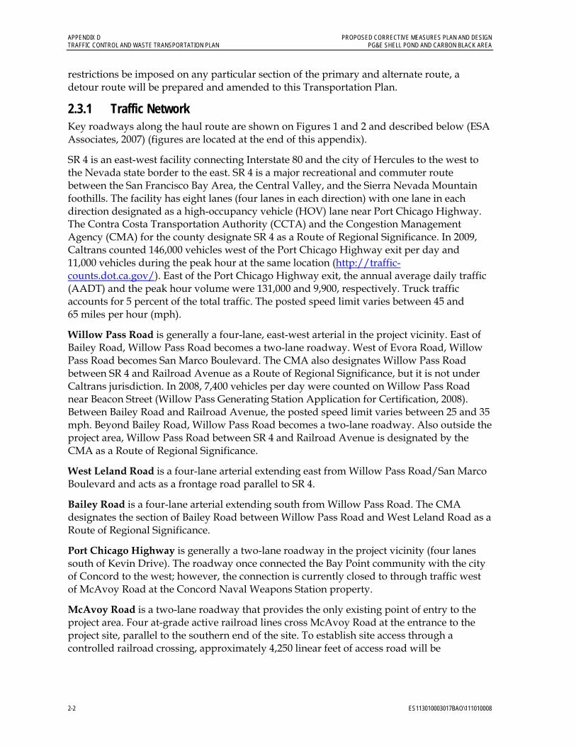
APPENDIX D PROPOSED CORRECTIVE MEASURES PLAN AND DESIGN TRAFFIC CONTROL AND WASTE TRANSPORTATION PLAN PG&E SHELL POND AND CARBON BLACK AREA
2-2 ES113010003017BAO\111010008
restrictions be imposed on any particular section of the primary and alternate route, a detour route will be prepared and amended to this Transportation Plan.
2.3.1 Traffic Network Key roadways along the haul route are shown on Figures 1 and 2 and described below (ESA Associates, 2007) (figures are located at the end of this appendix).
SR 4 is an east-west facility connecting Interstate 80 and the city of Hercules to the west to the Nevada state border to the east. SR 4 is a major recreational and commuter route between the San Francisco Bay Area, the Central Valley, and the Sierra Nevada Mountain foothills. The facility has eight lanes (four lanes in each direction) with one lane in each direction designated as a high-occupancy vehicle (HOV) lane near Port Chicago Highway. The Contra Costa Transportation Authority (CCTA) and the Congestion Management Agency (CMA) for the county designate SR 4 as a Route of Regional Significance. In 2009, Caltrans counted 146,000 vehicles west of the Port Chicago Highway exit per day and 11,000 vehicles during the peak hour at the same location (http://traffic-counts.dot.ca.gov/). East of the Port Chicago Highway exit, the annual average daily traffic (AADT) and the peak hour volume were 131,000 and 9,900, respectively. Truck traffic accounts for 5 percent of the total traffic. The posted speed limit varies between 45 and 65 miles per hour (mph).
Willow Pass Road is generally a four-lane, east-west arterial in the project vicinity. East of Bailey Road, Willow Pass Road becomes a two-lane roadway. West of Evora Road, Willow Pass Road becomes San Marco Boulevard. The CMA also designates Willow Pass Road between SR 4 and Railroad Avenue as a Route of Regional Significance, but it is not under Caltrans jurisdiction. In 2008, 7,400 vehicles per day were counted on Willow Pass Road near Beacon Street (Willow Pass Generating Station Application for Certification, 2008). Between Bailey Road and Railroad Avenue, the posted speed limit varies between 25 and 35 mph. Beyond Bailey Road, Willow Pass Road becomes a two-lane roadway. Also outside the project area, Willow Pass Road between SR 4 and Railroad Avenue is designated by the CMA as a Route of Regional Significance.
West Leland Road is a four-lane arterial extending east from Willow Pass Road/San Marco Boulevard and acts as a frontage road parallel to SR 4.
Bailey Road is a four-lane arterial extending south from Willow Pass Road. The CMA designates the section of Bailey Road between Willow Pass Road and West Leland Road as a Route of Regional Significance.
Port Chicago Highway is generally a two-lane roadway in the project vicinity (four lanes south of Kevin Drive). The roadway once connected the Bay Point community with the city of Concord to the west; however, the connection is currently closed to through traffic west of McAvoy Road at the Concord Naval Weapons Station property.
McAvoy Road is a two-lane roadway that provides the only existing point of entry to the project area. Four at-grade active railroad lines cross McAvoy Road at the entrance to the project site, parallel to the southern end of the site. To establish site access through a controlled railroad crossing, approximately 4,250 linear feet of access road will be

PROPOSED CORRECTIVE MEASURES PLAN AND DESIGN APPENDIX D PG&E SHELL POND AND CARBON BLACK AREA TRAFFIC CONTROL AND WASTE TRANSPORTATION PLAN
ES113010003017BAO\111010008 2-3
constructed to connect the PG&E Shell Pond to McAvoy Road at the former Harris Yacht Harbor, west of the site.
A gravel access road will be constructed parallel to the railroad tracks that is designed for an estimated 75 20- to 25-ton trucks per day for 1 year. A temporary bridge, founded on spread footings, will span the existing unlined stormwater ditch that runs from south of the railroad track into the slough on the west side of the PG&E Shell Pond. The temporary access road will be constructed by grading the proposed road alignment and placing a Class 2 subgrade enhancement geotextile to provide structural support and separation between the aggregate base and the native subgrade material. The geotextile will be overlain by approximately 16 inches of aggregate base or recycled aggregate base.
The proposed route comprises streets and highways with 11- to 12-foot-wide lanes that can accommodate the turning radii requirements for the haul trucks. There are no sharp curves or steep slopes along the route that would create a hazard for vehicles on the road.
2.3.2 Baseline Traffic SR 4 currently experiences traffic congestion on peak periods, as shown above in Table 16-1. Near the project site, truck traffic accounts for 5 percent of the total traffic on SR 4. Current truck traffic data are not available for non-Caltrans facilities.
The following graphs from the Caltrans Performance Measurement System (PeMS) depict the variations in traffic volume on Tuesday, March 2, 2011, on SR 4 at Port Chicago Highway in the eastbound and westbound directions. It clearly shows that the AM Peak hour is 7:00 a.m. Trucks transporting the material to the landfill will not start until 8:30 a.m., thereby avoiding peak traffic hours and times when children will be going to school.
Eastbound Traffic Volume: SR 4 at Port Chicago Highway, March 2, 2011
Source: Caltrans PeMS (http://pems.dot.ca.gov)

APPENDIX D PROPOSED CORRECTIVE MEASURES PLAN AND DESIGN TRAFFIC CONTROL AND WASTE TRANSPORTATION PLAN PG&E SHELL POND AND CARBON BLACK AREA
2-4 ES113010003017BAO\111010008
Westbound Traffic Volume: SR 4 at Port Chicago Highway, March 2, 2011
Source: Caltrans PeMS (http://pems.dot.ca.gov)
Tables 1 and 2 summarize local street and highway data; the tables show the available average daily traffic (ADT) and LOS for the local streets within the project vicinity (tables are located at the end of this appendix).
The proposed project activities will not conflict with any applicable plans, ordinances, or policies that have established measures of effectiveness for the performance of intersections, streets, pedestrian and bicycle paths, or mass transit. SR 4 is currently at an acceptable, but low, LOS during peak traffic periods (as low as LOS E); however, CCC has set LOS F as the acceptable LOS for SR 4 (Kimley-Horn and Associates, Inc., 2010).
The turning movement counts presented in the following exhibit (reprinted from the Application for Certification for the Willow Pass Generating Station [AFC] in Pittsburg, CA [URS Corporation [URS], 2008]) were collected in November 2007.

PROPOSED CORRECTIVE MEASURES PLAN AND DESIGN APPENDIX D PG&E SHELL POND AND CARBON BLACK AREA TRAFFIC CONTROL AND WASTE TRANSPORTATION PLAN
ES113010003017BAO\111010008
Existing Conditions Daily Average and Peak Hour Turning Movement Volumes
Notes: Street shown for purposes of analysis only. Not all street shown. XX(XX) AM (PM) Peak Hour Volumes. Source: URS, 2008.


PROPOSED CORRECTIVE MEASURES PLAN AND DESIGN APPENDIX D PG&E SHELL POND AND CARBON BLACK AREA TRAFFIC CONTROL AND WASTE TRANSPORTATION PLAN
ES113010003017BAO\111010008 2-7
Trucks hauling material to Keller Canyon Landfill will be the main source of a potential increase in traffic associated with the project. Because Keller Canyon Landfill currently closes at 3:30 p.m., project-related truck traffic will have a minimal impact on the PM Peak traffic at intersections along the haul route and on SR 4. During the AM Peak traffic period, trucks traveling eastbound on SR 4 will be traveling counter-commute and could choose to use alternate (surface) haul routes when returning from the landfill. The use of alternate haul routes will be addressed in the transportation management plan that will be prepared by the project construction contractor and submitted to DTSC prior to Phase 1 of the construction effort.
2.3.3 Primary Transportation Route Vehicles will exit the PG&E Shell Pond site at the westernmost access gate, approximately 100 feet east of McAvoy Road. From this point, they will follow the route shown on Figure 1 and described in Table 3. The route proceeds from the site to SR 4, continues east on SR 4 to Bailey Road, and follows Bailey Road south to the landfill entrance. This route was selected because: (1) it is very direct, requiring a minimal number of turns, (2) it affects the fewest residential neighborhoods, and (3) it does not pass near schools, public offices, or other significant public gathering places.
Figure 2 shows the proposed route, signalized intersections along the route, and the existing number of lanes per facility.
2.3.4 Alternative Route Vehicles will exit the PG&E Shell Pond site at the westernmost access gate, approximately 100 feet east of McAvoy Road. From this point, they will follow the route shown on Figure 1 and described in Table 4. The route proceeds south to W. Leland Road, continues east on W. Leland Road to Bailey Road, and follows Bailey Road south to the landfill entrance. This route has similar selection qualifications as the primary route but is considered a secondary route because it is closer to the housing development immediately south of W. Leland Road.
This alternative route will be used if there is construction in the area to implement improvements on adjacent highways, such as those proposed by CCC on Bailey Road (between SR 4 and W. Leland Road), in order to minimize traffic during construction.
2.4 Public Road Transport Considerations An estimated 75 to 80 truckloads will be required each day to transport material from the PG&E's Pond Site to Keller Canyon Landfill. The following plans and procedures will be followed to minimize immediate and long-term impacts associated with this work:
Trucking will occur up to 6 days per week (Monday through Saturday) between the hours of 8:30 a.m. and 3:00 p.m. on weekdays, and between 8:00 a.m. and 1:00 p.m. on Saturdays. Baseline flow information shows the AM Peak is 7:00 a.m., and hauling will begin after a decline in the AM Peak flow.
Employees at the worksite will be encouraged to use carpools or public transit. There will be a designated parking lot for workers at the project location, as shown on Figure 1. The amount of staff at the project site is anticipated to be low (5 to 6 at any given time), and will not cause a significant impact on local road traffic.

APPENDIX D PROPOSED CORRECTIVE MEASURES PLAN AND DESIGN TRAFFIC CONTROL AND WASTE TRANSPORTATION PLAN PG&E SHELL POND AND CARBON BLACK AREA
2-8 ES113010003017BAO\111010008
A photographic survey will be performed along the planned routes of travel prior to initiating transport of material. The survey will serve to document current road conditions. Roadway conditions after completion of material transport will be compared to this photo documentation, and roadway sections damaged by material movement will be restored to their pre-existing conditions.
Trucks moving between the PG&E Shell Pond site and Keller Canyon Landfill will be appropriately staged at the site along the temporary road (see Figure 1) to maximize efficiency and minimize idling vehicles on public roadways. Truck drivers will be instructed to minimize unnecessary stops on public roadways, to maintain speeds no greater than posted speed limits, and to operate their vehicles in ways that minimize excessive noise and emissions.
Control measures will be implemented to minimize impacts on public roads and to maintain safe passage for all vehicles and pedestrians. Tables 3 and 4 identify planned traffic control measures to be employed along each transportation route. Traffic patterns and safety of operations will be continually monitored, and modifications will be made to haul routes, traffic control measures, and transport scheduling, as necessary, to address changes in conditions.
The haul route (excluding SR 4) will be swept every morning during off-peak hours on days of active hauling to/from Keller Canyon Landfill.
A 1-800 telephone number will be posted on all trucks and along the haul route for real-time communication on project-related traffic issues.
The project will not conflict with adopted policies, plans, or programs. Keller Canyon Landfill is currently permitted to receive 320 trucks per day and is requesting an increase to 395 trucks per day (CCC, 2010a). Thus, the proposed number of trucks associated with the project will be consistent with current plans regarding truck traffic. Improvements for pedestrian and bicycle traffic on Bailey Road and along portions of Willow Pass Road are currently under review by CCC (2010b; 2010c). Project-related traffic will not conflict with implementation of these plans, if approved. In addition, project-related traffic will be of relatively short duration (approximately 6 to 7 months).
The closest public transit to the project site is a Tri-Delta Transit bus stop serving Routes 201 and 389. The stop is located at Port Chicago Highway and Pacifica Avenue (Tri-Delta Transit, 2011). This bus stop is approximately two blocks south of the intersection of McAvoy Road and Port Chicago Highway. Project-related traffic is not expected to have a significant impact on the availability of this bus stop.
The current pavement condition will be documented by video or photographs. Any roadway sections along the haul route damaged by the heavy construction vehicles will be restored to their current conditions. With implementation of measures included in the transportation management plan, impacts will be less than significant.

PROPOSED CORRECTIVE MEASURES PLAN AND DESIGN APPENDIX D PG&E SHELL POND AND CARBON BLACK AREA TRAFFIC CONTROL AND WASTE TRANSPORTATION PLAN
ES113010003017BAO\111010008 2-9
2.5 Material Loading Procedures 2.5.1 Traffic Control On- and Offsite All staging of haul vehicles will occur within the boundary of the PG&E Shell Pond site. Truck traffic and scheduling will be coordinated by the PG&E project manager or his/her representative and a representative of the trucking contractor to be sure that truck arrivals are staggered to avoid traffic conflicts on city streets. After receiving clearance, the truck will move from the staging area to the Material Handling Area. After loading, the truck will be guided through the prescribed exit procedures, including cleaning and checkout, and then onto the route to the landfill.
As previously discussed, the project construction contractor will prepare and submit a transportation management plan to DTSC prior to Phase 1 of the construction effort. The transportation management plan will supplement this Plan; it will address potential issues associated with the period when haul trucks deliver NNM to the offsite landfill. The transportation management plan will address traffic management near sensitive locations (e.g., schools, community center, and library) and will include measures to minimize effects on local intersections and SR 4 during peak traffic hours. Such measures will include using alternate haul routes such as West Leland Road or Willow Pass Road, avoiding the use of SR 4 for hauling during peak hours, discontinuing hauling activities during peak hours, and timing of onsite construction worker shifts to minimize impacts due to worker trips. Pedestrian facilities are scarce in the vicinity of the project, and all crosswalks traversing the proposed haul routes are either signalized or stop-controlled. The transportation management plan will also address potential impacts on pavement along the haul route(s).
2.5.2 Traffic Control during Loading Staging will vary during excavation and load-out. Loading of mechanically removed materials will occur south of the PG&E Shell Pond; loading of hydraulically removed NNM from the pond will occur in the Material Handling Area. The soil will be loaded by using a rubber-tire front-end loader or an excavator. Loading will be gentle to minimize the potential for spills or dust creation. No loading will be performed during high winds or storms. The end-dump truck boxes will be covered with tarpaulins prior to exiting the site.
After the loads have been covered, the truck will proceed to the truck cleaning area. Soil on the outside of the truck and on the tires will be removed by using a broom and/or high-pressure washer. Under no circumstances will a truck leave the site without being cleaned.
After cleaning, trucks will proceed to an inspection area for inspection and to receive necessary documentation. The inspection will include a visual check for proper covering, cleaning procedures, and hauling documents. The inspection results will be logged in the daily transportation logs maintained by the PG&E Shell Pond site construction manager.
A manifest will be pre-prepared for each truckload. A non-hazardous manifest will be given to the driver for signature. The field engineer will retain the generator’s copy for logging and tracking purposes.


ES113010003017BAO\111010008 3-1
3.0 Record Keeping
3.1 Field Record A daily transportation log will be maintained by the PG&E Shell Pond site construction manager. The log will record the following information for each load:
Date of loading Time of loading Vehicle identification Truck driver’s name Trucking company Approximate volume/weight of load Documentation that decontamination was performed Documentation as to whether or not odor-reducing agents were used Documentation that an inspection was performed prior to the truck leaving the site Comments or remarks
Implementation of this Transportation Plan will be the responsibility of the construction contractor, construction manager, or other designated traffic coordinator. The person responsible for implementing this Plan will be determined after formal contract award of the project, and DTSC will be notified.
3.2 Non-Hazardous Waste Manifest Distribution The non-hazardous waste manifest, or the bill of lading for each shipment of non-hazardous waste, will be kept by the driver in the appropriate document pocket located in the driver’s door. The driver will be responsible for handing over the manifest or the bill of lading to the disposal facility for signature and processing. The disposal facility will send the yellow copy to the generator within 30 days.
3.3 Plan Distribution The trucking contractor will be responsible for distributing to each truck driver a copy of this Transportation Plan, which describes the transportation routes and provides special instructions for emergency procedures and contacts. The truck driver will keep this Plan in the truck.
3.4 Training Requirements for Truck Drivers and Flaggers The Health and Safety Plan (see Appendix G of the PCMPD) provides additional guidelines for drivers on the site and for heavy equipment, as well as all the training requirements and safety information for the project. This section summarizes the requirements for the truck drivers and flaggers.
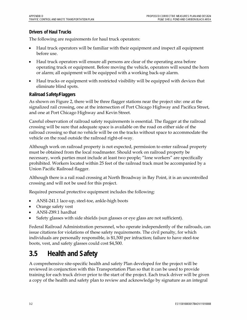
APPENDIX D PROPOSED CORRECTIVE MEASURES PLAN AND DESIGN TRAFFIC CONTROL AND WASTE TRANSPORTATION PLAN PG&E SHELL POND AND CARBON BLACK AREA
3-2 ES113010003017BAO\111010008
Drivers of Haul Trucks The following are requirements for haul truck operators:
Haul truck operators will be familiar with their equipment and inspect all equipment before use.
Haul truck operators will ensure all persons are clear of the operating area before operating truck or equipment. Before moving the vehicle, operators will sound the horn or alarm; all equipment will be equipped with a working back-up alarm.
Haul trucks or equipment with restricted visibility will be equipped with devices that eliminate blind spots.
Railroad Safety/Flaggers As shown on Figure 2, there will be three flagger stations near the project site: one at the signalized rail crossing, one at the intersection of Port Chicago Highway and Pacifica Street, and one at Port Chicago Highway and Kevin Street.
Careful observation of railroad safety requirements is essential. The flagger at the railroad crossing will be sure that adequate space is available on the road on either side of the railroad crossing so that no vehicle will be on the tracks without space to accommodate the vehicle on the road outside the railroad right-of-way.
Although work on railroad property is not expected, permission to enter railroad property must be obtained from the local roadmaster. Should work on railroad property be necessary, work parties must include at least two people; “lone workers” are specifically prohibited. Workers located within 25 feet of the railroad track must be accompanied by a Union Pacific Railroad flagger.
Although there is a rail road crossing at North Broadway in Bay Point, it is an uncontrolled crossing and will not be used for this project.
Required personal protective equipment includes the following:
ANSI-241.1 lace-up, steel-toe, ankle-high boots Orange safety vest ANSI-Z89.1 hardhat Safety glasses with side shields (sun glasses or eye glass are not sufficient).
Federal Railroad Administration personnel, who operate independently of the railroads, can issue citations for violations of these safety requirements. The civil penalty, for which individuals are personally responsible, is $1,500 per infraction; failure to have steel-toe boots, vest, and safety glasses could cost $4,500.
3.5 Health and Safety A comprehensive site-specific health and safety Plan developed for the project will be reviewed in conjunction with this Transportation Plan so that it can be used to provide training for each truck driver prior to the start of the project. Each truck driver will be given a copy of the health and safety plan to review and acknowledge by signature as an integral

PROPOSED CORRECTIVE MEASURES PLAN AND DESIGN APPENDIX D PG&E SHELL POND AND CARBON BLACK AREA TRAFFIC CONTROL AND WASTE TRANSPORTATION PLAN
ES113010003017BAO\111010008 3-3
part of this Transportation Plan. An emergency contact list will be included in the health and safety Plan.


ES113010003017BAO\111010008 4-1
4.0 Contingency Plan/Emergency Response
In the event of a breakdown or accident:
The truck driver will notify the PG&E Shell Pond site construction manager and promptly arrange for repairs or emergency roadside service. The site construction manager will notify the trucking company as soon as possible of any breakdown that results in lost time of delivery of the manifested load.
In the event that loads are rejected at the landfill:
If the materials are tested and determined to be hazardous, the truck driver will notify the site construction manager, and deliver the load to Beatty, Nevada. The waste characterization plan (see Appendix B of the PCMPD) provides more detail.
In the event of an accident with no spillage of hazardous material:
The truck driver will notify the PG&E Shell Pond site construction manager, promptly arrange for repairs or emergency roadside service, and notify the local fire department, CHP, and police by phoning 911, as directed by the trucking company.
In the event of an accident with spillage of NNM:
The truck driver will perform the steps outlined above as well as inform PG&E and the construction contractor to mobilize a cleanup crew.
Although the material being transported to the landfill will be non-hazardous, an incident report will be prepared by the construction contractor and submitted to DTSC within 24 hours, as specified in CCR Title 22, Section 66263.41(h). The local sheriff’s department, CHP, or police will also be notified by phoning 911. Other numbers to call are listed in the health and safety plan (see Appendix G of the PCMPD), including the numbers for the fire department, emergency response, and PG&E contacts.


ES113010003017BAO\111010008 5-1
5.0 References
California Department of Toxic Substances Control (DTSC). 2001. Guidance of Developing Transportation Plans for Removal or Remedial Actions. Interim final. December 5.
California Department of Transportation (Caltrans). 2011a. Caltrans Performance Measurement System (PeMS) Web site. Online: http://pems.dot.ca.gov
_______. 2011b. Traffic and Vehicle Data Systems Unit 2009 All Traffic Volumes on California State and Highway System. Online: http://traffic-counts.dot.ca.gov/2009all/2009TrafficVolumes.htm
CH2M HILL. 2010. Bench Test and Pilot Study Report. November.
Contra Costa County (CCC). 2010a. Keller Canyon Landfill Application. Online: http://www.co.contra-costa.ca.us/index.aspx?NID=2165
_______. 2010b. Bailey Road Pedestrian & Bicycle Improvement Plan. Online: http://www.co.contra-costa.ca.us/index.aspx?NID=2368
_______. 2010c. Willow Pass Road Safety Improvements, Phase 1. Online: http://www.co.contra-costa.ca.us/index.aspx?NID=2488
ESA Associates. 2007. Bay Point Waterfront Strategic Plan Environmental Impact Report. Prepared for Contra Costa County Redevelopment Agency. March. Online: http://www.ccreach.org/index.cfm
Kimley-Horn and Associates, Inc. 2010. 2009 Congestion Monitoring Program Final Draft Monitoring Report. Prepared for Contra Costa Transportation Authority (CCTA). March. Online: http://www.ccta.net/EN/main/planning/354/2009_CMP.html
Pittsburg, City of. 2011. Traffic Volume Count by Street. Last accessed on April 1, 2011. Online: http://www.ci.pittsburg.ca.us/index.aspx?page=193
Tri-Delta Transit. 2011. Route 389 Map. Online: http://transit.511.org/accessible/schedules/RouteMap.aspx?cid=3D&rte=8792
URS Corporation. 2008. Application for Certification for Willow Pass Generating Station, Pittsburg, California. Prepared for Mirant Willow Pass LLC. June. Online: http://www.energy.ca.gov/sitingcases/willowpass/documents/applicant/afc/index.php


Figures

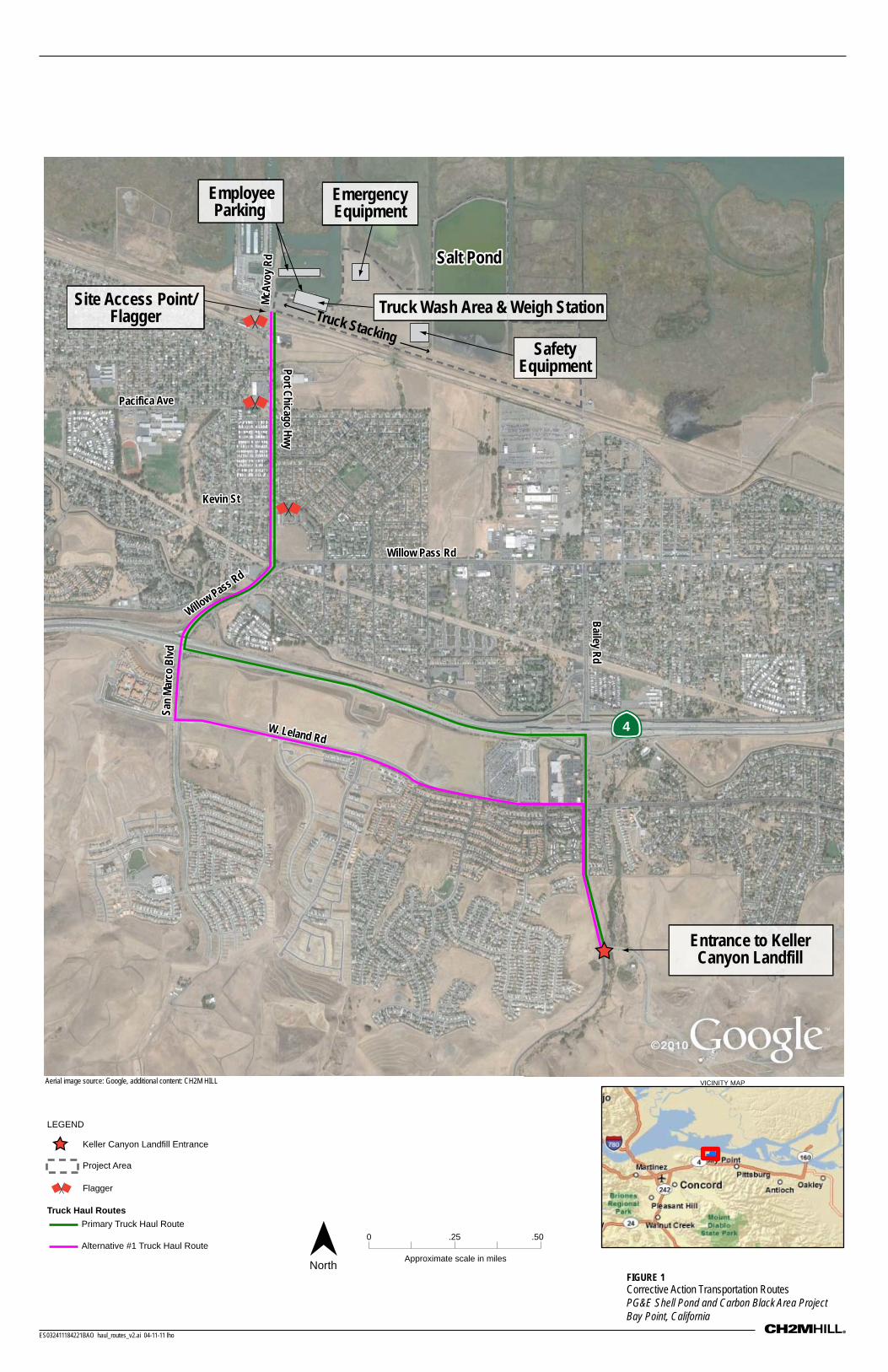
FIGURE 1 Corrective Action Transportation RoutesPG&E Shell Pond and Carbon Black Area ProjectBay Point, California
Aerial image source: Google, additional content: CH2M HILL
ES032411184221BAO haul_routes_v2.ai 04-11-11 lho
Salt PondSalt PondSalt Pond
Port Chicago H
wy
Port Chicago H
wy
Bailey R
dB
ailey Rd
Willow Pass RdWillow Pass Rd
Willow Pass Rd
Willow Pass Rd
San
Mar
co B
lvd
San
Mar
co B
lvd
W. Leland RdW. Leland Rd
Port Chicago H
wy
McA
voy
Rd
McA
voy
Rd
Bailey R
d
Willow Pass Rd
Willow Pass Rd
Pacifica AvePacifica Ave
Kevin StKevin St
San
Mar
co B
lvd
W. Leland Rd
North
0 .50.25
Approximate scale in miles
LEGEND
Truck Haul Routes
Keller Canyon Landfill Entrance
Project Area
Primary Truck Haul Route
Alternative #1 Truck Haul Route
VICINITY MAP
4
Entrance to Keller Canyon Landfill
Site Access Point/Flagger
EmployeeParking
Truck Wash Area & Weigh Station
Safety Equipment
Truck Stacking
Emergency Equipment
Flagger

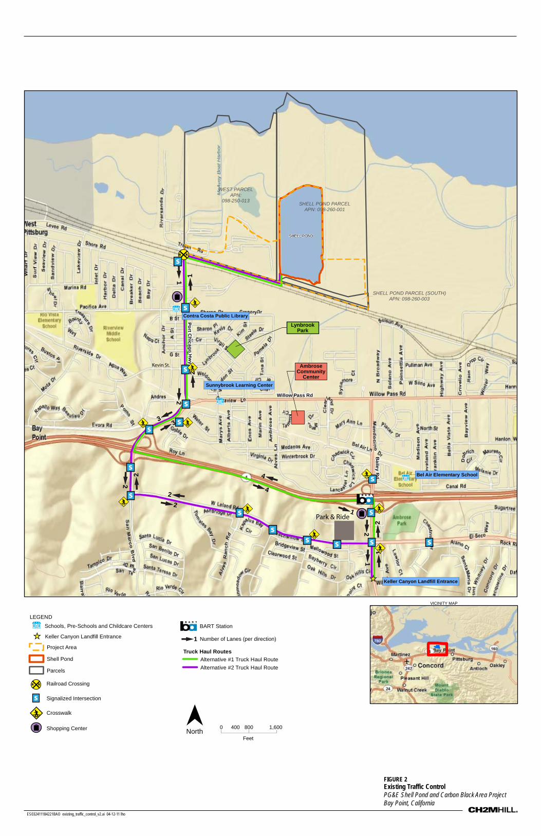
Bel Air Elementary School
Contra Costa Public Library
"?
"?
"?
Po
rt Ch
ica
go
Hw
y
Willow Pass Rd
Ba
iley
Rd
_̂ Keller Canyon Landfill Entrance
SHELL POND PARCEL (SOUTH)APN: 098-260-003
SHELL POND
WEST PARCELAPN:
098-250-013SHELL POND PARCEL
APN: 098-260-001
400 800 1,6000North
Feet
Park & Ride
Kevin St.
21
2
2
3
2
2
2
2
1
1
2
3
4
1
4
1
Sunnybrook Learning Center
Project Area
Shell Pond
Parcels
Truck Haul Routes
Alternative #1 Truck Haul Route
Alternative #2 Truck Haul Route
Keller Canyon Landfill Entrance
Schools, Pre-Schools and Childcare Centers
Railroad Crossing
Signalized Intersection
Crosswalk
Shopping Center
Number of Lanes (per direction)1
VICINITY MAP
_̂
LEGEND
"? BART Station
Lynbrook Park
AmbroseCommunity
Center
ES032411184221BAO existing_traffic_control_v2.ai 04-12-11 lho
FIGURE 2 Existing Traffic ControlPG&E Shell Pond and Carbon Black Area ProjectBay Point, California


Tables


PROPOSED CORRECTIVE MEASURES PLAN AND DESIGN APPENDIX D PG&E SHELL POND AND CARBON BLACK AREA TRAFFIC CONTROL AND WASTE TRANSPORTATION PLAN
ES113010003017BAO\111010008 TABLES-1
TABLE 1 Roadway Traffic Volumes Available PG&E Shell Pond and Carbon Black Area, Bay Point, California
Roadway Segment ADT Date Source
SR 4 West of Port Chicago Highway
146,000
(11,000 peak hour)
2009 Caltrans (2011b)
SR 4 East of Port Chicago Highway
131,000
(9,900 peak hour)
2009 Caltrans (2011b)
Bailey Road SR4 WB ramps to Willow Pass Road
11,550 2008 Willow Pass Generating Station AFC (URS, 2008)
Bailey Road South City Limits to West Leland Road
30,577 November 2006 City of Pittsburg (2011)
Bailey Road West Leland Road to SR 4
17,400 1990 City of Pittsburg (2011)
Willow Pass Road Bailey Road to Loftus Road
12,600 2008 Willow Pass Generating Station AFC (URS, 2008)
Willow Pass Road Loftus Road to N. Parkside Drive Ramps
14,800 2008 Willow Pass Generating Station AFC (URS, 2008)
Willow Pass Road N. Parkside Drive Ramps to W. 10th Street
7,400 2008 Willow Pass Generating Station AFC (URS, 2008)
Willow Pass Road Range Road to West 10th Street
7,050 August 2002 City of Pittsburg (2011)
Willow Pass Road West city Limits to Range Road
17,255 2000 City of Pittsburg (2011)
West Leland Road Range Road to Bailey Road
17,126 November 2006 City of Pittsburg (2011)
West Leland Road Bailey to West City Limits
9,034 November 2006 City of Pittsburg (2011)

APPENDIX D PROPOSED CORRECTIVE MEASURES PLAN AND DESIGN TRAFFIC CONTROL AND WASTE TRANSPORTATION PLAN PG&E SHELL POND AND CARBON BLACK AREA
TABLES-2 ES113010003017BAO\111010008
TABLE 2 Intersection Levels of Service Available PG&E Shell Pond and Carbon Black Area, Bay Point, California
Intersection Traffic Control AM Peak LOS PM Peak LOS Date Source
Port Chicago Hwy/McAvoy Rd
Stop controlled B A 2007 Bay Point EIR (ESA, 2007)
Port Chicago Hwy/Pacifica Ave
Signal A A 2007 Bay Point EIR (ESA, 2007)
Port Chicago Hwy/Riverside Dr/Lynbrook St
Signal A A 2007 Bay Point EIR (ESA, 2007)
Port Chicago Hwy/Willow Pass Rd
Signal A A 2007 Bay Point EIR (ESA, 2007)
San Marco Blvd/SR4 EB Ramps
Signal A A 2007 Bay Point EIR (ESA, 2007)
Willow Pass Rd/Alves Ln
Signal A A 2007 Bay Point EIR (ESA, 2007)
Willow Pass Rd/Bailey Rd
Signal A A 2008 Willow Pass AFC (URS, 2008)
Willow Pass Rd/Loftus Rd
Signal A A 2008 Willow Pass AFC (URS, 2008)
Willow Pass Rd/N. Parkside Dr WB Ramps
Yield Signal B B 2008 Willow Pass AFC (URS, 2008)
Willow Pass Rd/N. Parkside Dr EB Ramps
Stop controlled B B 2008 Willow Pass AFC (URS, 2008)
Bailey Rd/SR 4 WB Ramps
Signal A A 2008 Willow Pass AFC (URS, 2008)
Bailey Rd/SR4 EB Ramps
Signal A A 2008 Willow Pass AFC (URS, 2008)

PROPOSED CORRECTIVE MEASURES PLAN AND DESIGN APPENDIX D PG&E SHELL POND AND CARBON BLACK AREA TRAFFIC CONTROL AND WASTE TRANSPORTATION PLAN
ES113010003017BAO\111010008 TABLES-3
TABLE 3 Primary Transportation Route Between Shell Pond Site and Keller Canyon Landfill PG&E Shell Pond and Carbon Black Area, Bay Point, California
Total Distance Traveled Action
Distance to Next Action
Estimated Travel Time For This Leg
(minutes) Notes and Planned Control Measures Minimum Maximum
0 Begin route at western site gate on McAvoy Road
200 ft 0 0 Signage to be placed on McAvoy Rd., north and south of site entrance, to warn of truck traffic entering and exiting.
200 ft Enter McAvoy Road, heading south, cross SPRR railroad tracks, proceed to Port Chicago Highway
0.1 mi 2 10 Possible delays due to railroad traffic
0.1 mi Turn left onto Port Chicago Highway, heading south. Proceed to Willow Pass Road
0.7 mi 3 5 Signage to be placed on Port Chicago Hwy., north and south McAvoy Rd. to warn of truck traffic entering and exiting.
0.8 mi Turn right onto Willow Pass Road. Proceed to onramp to eastbound SR 4
0.3 mi 1 2
1.1 mi Enter onto eastbound Highway 4, and proceed to Bailey Road offramp.
1.4 mi 2 15
2.5 mi Take Bailey Road offramp from SR 4 eastbound. Proceed to Bailey Road at base of offramp
0.3 mi 1 1
2.8 mi Turn right onto Bailey Road. Proceed to entrance of Keller Canyon Landfill.
0.5 mi. 2 5
3.3 mi Turn left into Keller Canyon Landfill
0 0 0
Total Travel Time (minutes): 11 38

APPENDIX D PROPOSED CORRECTIVE MEASURES PLAN AND DESIGN TRAFFIC CONTROL AND WASTE TRANSPORTATION PLAN PG&E SHELL POND AND CARBON BLACK AREA
TABLES-4 ES113010003017BAO\111010008
TABLE 4 Alternative Transportation Route Between Shell Pond Site and Keller Canyon Landfill PG&E Shell Pond and Carbon Black Area, Bay Point, California
Total Distance Traveled Action
Distance to Next
Action
Estimated Travel Time for this Leg
(minutes) Notes and Planned Control Measures Minimum Maximum
0 Begin route at western site gate on McAvoy Road
200 ft 0 0 Signage to be placed on McAvoy Rd., north and south of site entrance, to warn of truck traffic entering and exiting.
200 ft Enter McAvoy Road, heading south, cross SPRR railroad tracks, proceed to Port Chicago Highway
0.1 mi 2 10 Possible delays due to railroad traffic
0.1 mi Turn left onto Port Chicago Highway, heading south. Proceed to Willow Pass Road
0.7 mi 3 5 Signage to be placed on Port Chicago Hwy., north and south McAvoy Rd. to warn of truck traffic entering and exiting.
0.8 mi Turn right onto Willow Pass Road. Proceed south past the Highway 4 undercrossing (Willow Pass Road becomes San Marco Blvd.) to W. Leland Rd.
0.6 mi 3 4
1.4 mi Turn left onto W. Leland Rd and proceed east to Bailey Road.
1.4 mi 3 7
2.8 mi Turn right onto Bailey Road. Proceed to entrance of Keller Canyon Landfill.
0.4 mi. 2 2
3.2 mi Turn left into Keller Canyon Landfill
0 0 0
Total Travel Time (minutes): 13 28

Appendix E Environmental Compliance Monitoring Plan


A p p e n d i x E
Environmental Compliance Management Plan
PG&E Shell Pond and Carbon Black Area,
Bay Point, California Prepared for
Pacific Gas and Electric Company
December 2010
155 Grand Avenue, Suite 800
Oakland, CA 94612


ES113010003017BAO\111010006 I
Contents
1.0 Introduction ......................................................................................................................... 1-1 1.1 Applicability of ECMP ........................................................................................... 1-1 1.2 Contents of ECMP .................................................................................................. 1-1 1.3 Release to Construction (RTC) .............................................................................. 1-2 1.4 Project-Level Roles and Responsibilities ............................................................. 1-2
1.4.1 Construction Contractor’s Team ............................................................. 1-3 1.4.2 Environmental Consultant Project Team ............................................... 1-4
1.5 Compliance Inspection and Reporting ................................................................ 1-8 1.5.1 Environmental Inspection Frequency .................................................... 1-8 1.5.2 Compliance Levels .................................................................................... 1-8 1.5.3 Protocols for Halting or Redirecting Construction Activities ............. 1-9 1.5.4 Compliance Reporting and Documentation Procedures ..................... 1-9 1.5.5 Documentation ........................................................................................ 1-11
1.6 Notifications .......................................................................................................... 1-11 1.6.1 Routine Notifications .............................................................................. 1-12 1.6.2 Grounds for Immediate Notification .................................................... 1-12
1.7 Environmental Training ...................................................................................... 1-13 1.7.1 General Crew Training ........................................................................... 1-13 1.7.2 Tailboard Training .................................................................................. 1-14
1.8 Communication Protocols ................................................................................... 1-14 1.8.1 Meetings ................................................................................................... 1-14 1.8.2 Biological Monitor Communication Protocol ...................................... 1-14 1.8.3 Cultural and Paleontological Resources Communication
Protocol ..................................................................................................... 1-15 1.8.4 Communications with the Public .......................................................... 1-15 1.8.5 Communications with the Press ............................................................ 1-15 1.8.6 Conflict Resolution .................................................................................. 1-16
1.9 Variance Process ................................................................................................... 1-16 1.9.1 Temporary Extra Workspace Requests ................................................ 1-16 1.9.2 Project Modifications/Variance Requests ........................................... 1-17
1.10 Construction Contract Specifications and Enforcement ................................. 1-17 1.11 Quality Assurance Assessments......................................................................... 1-17
2.0 Biological and Wetland Avoidance and Minimization Measures and Monitoring ........................................................................................................................... 2-1 2.1 Avoidance and Minimization Measures and Best Management Practices .... 2-1 2.2 General Biological and Wetland Monitoring...................................................... 2-2 2.3 Species-Specific Biological Monitoring ............................................................... 2-3
2.3.1 Salt Marsh Harvest Mouse ....................................................................... 2-3 2.3.2 California Clapper Rail and California Black Rail ................................ 2-3 2.3.3 Other Special Status Birds ........................................................................ 2-3 2.3.4 Delta Smelt and Longfin Smelt ................................................................ 2-4 2.3.5 Salmonids and Green Sturgeon ............................................................... 2-4

APPENDIX E PROPOSED CORRECTIVE MEASURES PLAN AND DESIGN BIOLOGICAL MONITORING PLAN PG&E SHELL POND AND CARBON BLACK AREA
ii ES113010003017BAO\111010006
Attachments
1 Project-Specific Environmental Compliance Management Plan 2 Compliance Level Scenarios 3 Environmental Inspection Report Form 4 Specialty Monitoring Report Form 5 Noncompliance Notice Form 6 Noncompliance Resolution Report Form 7 Sample Compliance Summary Report 8 Sample Supervisor Training Agenda and Training Attendance Log 9 Temporary Extra Workspace Request Form 10 Environmental Variance Request Form
Table
1 Definitions and Examples of Compliance Levels and Consultant Environmental Inspector Reporting

ES113010003017BAO\111010006 1-1
1.0 Introduction
PG&E is committed to fully complying with the applicable environmental rules and regulations of federal, state, and local agencies. PG&E’s goal is to meet those requirements in the pursuit of a cleaner, safer environment for future operations in California.
This Environmental Compliance Management Plan (ECMP) for the PG&E Shell Pond and Carbon Black Area project (Project) was developed to focus on building and maintaining cooperative working relationships and effective communications among PG&E environmental and construction personnel, contractors, and agency representatives. It is based on the 2010 guidelines of the PG&E Environmental Compliance Management Plan for Large-Scale Transmission Construction Projects: Final Draft for Pilots report, guides project teams and ultimately ensures that environmental commitments are met throughout every phase of construction on major gas and electric transmission projects primarily.
The goals of the PG&E Shell Pond and Carbon Black Area ECMP are to:
establish effective environmental compliance management so that the Project is constructed in compliance with all environmental permit conditions, mitigation measures, and regulatory requirements
demonstrate and maintain PG&E’s leadership position with regards to environmental compliance management during Project construction
promote consistency across the Project teams and lines of business in how PG&E approaches environmental compliance management during construction
communicate the Project environmental compliance management approach to permitting agencies
1.1 Applicability of ECMP This ECMP primarily applies to the construction phase of a Project, after a Project has obtained all environmental permits and is released to construction by Land and Environmental Management or Environmental Operations.
1.2 Contents of ECMP The ECMP describes the organizational strategies and methods that PG&E will implement to realize its environmental commitments and provides guidance regarding the company’s approach to environmental compliance management and inspection during construction of the PG&E Shell Pond and Carbon Black Area Project. The ECMP is divided into the following sections:
Section 1.3 describes PG&E’s process for releasing construction projects when all necessary land rights (as applicable) and permits and have been secured.

APPENDIX E PROPOSED CORRECTIVE MEASURES PLAN AND DESIGN BIOLOGICAL MONITORING PLAN PG&E SHELL POND AND CARBON BLACK AREA
1-2 ES113010003017BAO\111010006
Section 1.4 provides an overview of project-level roles and responsibilities for environmental compliance management.
Section 1.5 describes the Project environmental compliance inspection and reporting system.
Section 1.6 details the Project approach to environmental notifications.
Section 1.7 provides an overview of the Project environmental training approach.
Section 1.8 explains the communication protocols that the Project will use before and during the construction phase of the Project.
Section 1.9 describes the Project internal and agency variance review and approval processes.
Section 1.10 provides an overview of how the Project will ensure that environmental best practices and permit requirements are reflected in the Project contract specifications for construction contractors and job packages for PG&E crews.
Section 1.11 outlines procedures for quality assurance assessments to verify field compliance and ensure the various components of the ECMP are being applied consistently to all projects that meet the applicable criteria.
1.3 Release to Construction (RTC) The Release to Construction (RTC) process helps to ensure that parties associated with construction activities have the necessary information to comply with land rights (as applicable) and environmental regulations. The PG&E Shell Pond and Carbon Black Area Project does not require the acquisition of a land entitlement but does require discretionary permit from a governmental agency (e.g., the California Public Utilities Commission, United States Fish & Wildlife Service, Regional Water Quality Control Boards, etc.), and will require a formal “Release to Construction” issued from Land and Environmental Management or Environmental Operations before any construction activity can occur on the Project. The RTC package will contain all of the pertinent information necessary for the Project to proceed.
The RTC package for the PG&E Shell Pond and Carbon Black Area will include environmental permits and specific conditions associated with the permits, including, but not limited to: Notice to Proceed conditions, training requirements, implementing Best Management Practices (BMPs), tailboards, documentation, reporting, and compliance contacts. The RTC will include all relevant conditions that need to be complied with before construction can proceed, and/or it will reference attached documents. The RTC will also include copies of all environmental permits that need to remain at the job site.
1.4 Project-Level Roles and Responsibilities The following subsection identifies key project participants and describes their individual roles, responsibilities, and reporting relationships. Attachment 1will be used to identify specific names and contact information for the roles described in this section once the appropriate individuals are known.

PROPOSED CORRECTIVE MEASURES PLAN AND DESIGN APPENDIX E PG&E SHELL POND AND CARBON BLACK AREA BIOLOGICAL MONITORING PLAN
ES113010003017BAO\111010006 1-3
1.4.1 Construction Contractor’s Team 1.4.1.1 Construction Contractor Superintendent (PG&E’s Foreman when PG&E Crews are
Involved)1 The Construction Contractor Superintendent has significant responsibilities for compliance with the Project environmental requirements. The contractor’s supervisory staff will be responsible for incorporating applicable project environmental requirements into day-to-day construction activities. Key environmental responsibilities include but are not limited to:
verifying that all construction workers attend the project’s environmental training program prior to beginning work;
reviewing and understanding project environmental requirements and ensuring that sufficient labor and materials are provided to fully implement the environmental requirements during construction;
conferring daily with the Consultant Environmental Inspector (or Consultant Biological Monitor if these roles are merged) to review the construction schedule, discuss upcoming construction activities, and resolve environmental concerns;
responding to Environmental and Construction Inspector requests during construction to ensure compliance with project requirements;
looking ahead of construction to identify extra workspace needs, potential conflicts, and potential project variances;
requesting written authorization from the PG&E Construction Lead before working in any areas that are outside the approved work limits, or before conducting any activities that differ from what is authorized in the project permits; and
ensuring that work is performed in an environmentally responsible manner and in compliance with PG&E specifications, contract documents, environmental permits, approvals, landowner agreements, conditions, and applicable codes.
1.4.1.2 Contractor Environmental Compliance Lead The Project requires the construction contractor to designate a qualified Contractor Environmental Compliance Lead, whose responsibilities will include but not be limited to:
planning ahead for environmentally sensitive activities (e.g., work in or near streams and wetlands), and discussing specific approaches or concerns with the Consultant Environmental Inspector (or Consultant Biological Monitor if these roles are merged);
reviewing project-specific permits and specifications and communicating the requirements to the contractor’s employees;
confirming all contractor employees assigned to the job site attend any PG&E-provided environmental training;
1 For projects built by PG&E crews, the PG&E Foreman will assume the roles and responsibilities listed for both the PG&E Construction Inspector and the Contractor Superintendent.

APPENDIX E PROPOSED CORRECTIVE MEASURES PLAN AND DESIGN BIOLOGICAL MONITORING PLAN PG&E SHELL POND AND CARBON BLACK AREA
1-4 ES113010003017BAO\111010006
reporting environmental Occurrences and Noncompliance events through the project chain of command; and
ensuring rapid resolution of any environmental Occurrences or Noncompliance events.
1.4.2 Environmental Consultant Project Team The PG&E Environmental Compliance Lead will typically coordinate the environmental consultant team for the Project. However, it may be appropriate for a PG&E Project Environmental Discipline Lead to manage a specialty environmental consultant within their particular environmental discipline (e.g., biological monitors, cultural monitors, etc.). The PG&E Project Environmental Discipline Lead will be responsible for reporting information regarding their technical discipline to the PG&E Environmental Compliance Lead.
1.4.2.1 Consultant Environmental Compliance Supervisor The Consultant Environmental Compliance Supervisor directly manages the environmental consultant’s field personnel and supports PG&E’s Environmental Compliance Lead with overall management of the environmental inspection and specialty monitoring program during construction. Specific responsibilities of the Consultant Environmental Compliance Supervisor include but are not limited to:
assigning inspection staff for the various construction segments and providing direction on mitigation and permit requirements;
ensuring that Consultant Environmental Inspectors and Consultant Specialty Monitors (e.g., Consultant Biological Monitor) have proper tools, documents, equipment, and training to be effective;
reviewing Environmental Inspection Reports, Specialty Monitoring Reports, Noncompliance Notices, and Noncompliance Resolution Reports for quality and consistency;
communicating as needed with the PG&E Environmental Compliance Lead, PG&E Construction Lead, and other project staff regarding significant environmental issues and Noncompliance events;
tracking and ensuring proper resolution and documentation of noncompliant actions;
coordinating with the PG&E Construction Lead on schedule, construction progress, and variance needs, including reviewing and tracking the status of all variance requests;
coordinating preconstruction surveys and assigning Consultant Specialty Monitors to the field, as needed;
ensuring that public notification requirements are fulfilled during construction;
participating in regular project meetings with construction management, agency representatives, and contractor management personnel to ensure the integration of environmental issues into the construction process;
preparing and distributing the Compliance Summary Report to the distribution list that will be identified in Attachment 1;

PROPOSED CORRECTIVE MEASURES PLAN AND DESIGN APPENDIX E PG&E SHELL POND AND CARBON BLACK AREA BIOLOGICAL MONITORING PLAN
ES113010003017BAO\111010006 1-5
conducting regular environmental compliance quality assurance field reviews;
maintaining project files with thorough documentation of construction compliance and variance requests; and
providing leadership in communicating environmental responsibilities and requirements, safe work practices, and teamwork to the environmental inspection team.
1.4.2.2 Consultant Environmental Inspectors Consultant Environmental Inspectors are the primary field staff responsible for evaluating, documenting, and verifying that construction activities comply with all applicable mitigation requirements and state and local permit requirements. As discussed below, the number of Consultant Environmental Inspectors and their frequency of inspection may vary according to the construction schedule and regulatory and resource sensitivities. The Consultant Environmental Inspectors represent PG&E directly, and have the authority and responsibility to enforce the environmental requirements of project permits and mitigation measures. Specific responsibilities of the Consultant Environmental Inspector include but are not limited to:
thoroughly reviewing field implementation of all applicable plans (e.g., PG&E-prepared plans and contractor-prepared plans), permits, and specifications;
maintaining a copy of PG&E’s environmental contract specifications and PG&E’s internal RTC (including copies of environmental permits that need to remain on the job site) in their vehicle;
assessing work areas ahead of construction to anticipate environmental issues and providing advance notice to the construction management team of specific concerns and requirements;
installing environmental flagging and signage and verifying that construction limits have been marked, flagged, or fenced as required;
acting as a liaison on the construction site between construction personnel and agency field representatives;
coordinating daily with the Chief Construction Inspector regarding scheduled construction activities and associated environmental requirements;
documenting contractor compliance with Project mitigation requirements, permit conditions, and environmental specifications on a daily basis by assigning specific compliance levels in the Environmental Inspection Report (see Compliance Inspection and Reporting, below);
coordinating with the Chief Construction Inspector, PG&E Construction Lead, PG&E Environmental Compliance Lead, the contractor, and Agency Monitors as needed to ensure appropriate and timely resolution of compliance concerns;
working with the PG&E Environmental Compliance Lead and PG&E Construction Lead to issue Noncompliance Notices and Noncompliance Resolution Reports to the contractor when needed;

APPENDIX E PROPOSED CORRECTIVE MEASURES PLAN AND DESIGN BIOLOGICAL MONITORING PLAN PG&E SHELL POND AND CARBON BLACK AREA
1-6 ES113010003017BAO\111010006
coordinating with appropriate PG&E staff to halt or redirect a construction activity to prevent significant unauthorized impact to a sensitive resource (see below);
ensuring that overland travel routes and work areas are properly delineated and verifying that contractor personnel stay within approved work areas;
assisting the Consultant Environmental Compliance Supervisor with processing of variance requests, including reviewing the request in the field, taking photographs, and making mitigation recommendations;
conducting environmental training sessions and additional tailboard training in response to noncompliance activities or as needed prior to work in a sensitive resource area (e.g., stream);
performing the role of the Consultant Specialty Monitor (e.g., Consultant Biological Monitor) and Consultant SWPPP Inspector (if he or she has the appropriate qualifications); and
performing select responsibilities of the Consultant Environmental Compliance Supervisor as assigned by the PG&E Environmental Compliance Lead.
One of the Consultant Environmental Inspectors will be designated as the Consultant Lead Environmental Inspector if the Project requires more than one Consultant Environmental Inspector. The Consultant Lead Environmental Inspector will coordinate and oversee the activities of the Consultant Environmental Inspectors and Consultant Specialty Monitors. The Consultant Lead Environmental Inspector will coordinate daily with the Chief Construction Inspector and onsite Agency Monitors (if available) to facilitate compliance.
1.4.2.3 Consultant SWPPP Inspectors The PG&E Environmental Compliance Lead will work with Environmental Operations to arrange for compliance inspection of storm water best management practices (BMPs), compliance with the General Construction Storm Water Permit, and proper implementation of all site-specific elements of the Storm Water Pollution Prevention Plan (SWPPP). SWPPP Inspectors must be Qualified SWPPP Practitioners (QSPs) as defined by the General Construction Storm Water Permit (an individual with appropriate training and experience to implement the SWPPP and who will need to possess specific training and credentials by September 2010) or work under the QSP’s supervision, direction, and training. The roles of Consultant SWPPP Inspector and Consultant Environmental Inspector may be performed by the same individual if he or she has the appropriate qualifications, training, and experience. Responsibilities of the QSP (that may be delegated to the non-QSP SWPPP Inspectors working under the direction of the QSP) include but are not limited to:
Monitoring daily weather forecasts on the NOAA weather forecast webpage.
Taking daily onsite rain gage readings, if required by the project type.
Visually observing and confirming that storm water BMPs are performing adequately.
Verifying that BMPs specified in the SWPPP for storm water and non–storm water are being implemented in both areas where active construction is occurring (including

PROPOSED CORRECTIVE MEASURES PLAN AND DESIGN APPENDIX E PG&E SHELL POND AND CARBON BLACK AREA BIOLOGICAL MONITORING PLAN
ES113010003017BAO\111010006 1-7
staging areas) and in inactive areas (areas not actively constructed for more than 14 days).
Verifying that storm water discharges and authorized non-storm water discharges do not result in the deposition of sand, silt, and/or sediment into a wetland, water body, or storm drain.
Conducting daily unrecorded visual inspections of BMPs in active construction zones during working hours on Type 1 projects.
Photodocumenting the active construction site before, during, and after storm events, and uploading digital photos through the State Water Board’s SMARTS website once every three rain events.
Ensuring and documenting that responsible contractor personnel promptly (within 72 hours) begin repairing all ineffective BMPs.
Confirming that inactive project areas (more than 14 days without activity) are provided with temporary or final stabilization.
Confirming that project excavations and other areas of temporary soil disturbance are returned to preconstruction conditions or equivalent protection is provided (e.g., excavated soil hauled or covered at the end of each day) for Type 1 projects.
Confirming that road surfaces are cleaned of excavated material and construction materials at the end of each day for Type 1 projects.
1.4.2.4 Consultant Specialty Monitors The Project requires assigning a Consultant Specialty Monitors, specifically a Consultant Biological Monitor to protect sensitive biological. The Project does not require a cultural, and paleontological resource monitor. The roles of Consultant Biological Monitor and Consultant Environmental Inspector may be performed by the same individual, if he or she has the appropriate qualifications and experience. Specific responsibilities of the monitors include, but are not limited to:
Conducting biological surveys prior to construction, where required (Biological Monitor);
Monitoring specific construction activities where required by the CEQA document, permits, or other agency agreements;
Notifying the Consultant Lead Environmental Inspector and providing any required field assessment to address unanticipated discoveries of biological, cultural, or paleontological resources; and
Documenting activities and observations using the Specialty Monitoring Report or the Environmental Inspection Report if the Consultant Biological Monitor takes on the role as the Consultant Environmental Inspector (see Compliance Inspection and Reporting, below).

APPENDIX E PROPOSED CORRECTIVE MEASURES PLAN AND DESIGN BIOLOGICAL MONITORING PLAN PG&E SHELL POND AND CARBON BLACK AREA
1-8 ES113010003017BAO\111010006
1.5 Compliance Inspection and Reporting Proactive, qualified, and well-coordinated field inspection provides an essential foundation for successful environmental compliance during construction. During construction, the Consultant Environmental Inspectors and PG&E’s Construction Inspectors will be in the field inspecting for compliance with environmental requirements throughout construction of the Project. The Consultant Environmental Inspectors will have a prominent presence at the Project site and will work diligently to verify that work is conducted in an environmentally responsible manner and in compliance with the Project environmental permits and mitigation requirements. The Consultant Environmental Inspectors will also help facilitate the timely progression of the project by looking ahead of construction activities, identifying situations where environmental compliance issues may arise, and actively trouble-shooting with the PG&E Construction Lead and Chief Construction Inspector to resolve issues. The Consultant Environmental Inspectors will maintain effective communications and working relationships with the construction management team, contractor, and agency field representatives, and will cooperate in preventing and resolving Noncompliances during construction.
This section describes the Project approach to assessing, managing, and documenting environmental compliance during construction. It aims to resolve compliance issues in the field at the lowest level possible, while elevating more significant issues or reoccurring problems.
1.5.1 Environmental Inspection Frequency On a daily basis prior to the start of work the Consultant Environmental Inspector will:
Inspect all areas of the work area to ensure that no special status species are in the work area.
Inspect the active portions of the access road;
Verify the limits of the work areas and staging area, and the locations of access roads and ensure that they are properly marked before the construction begins.
Verify the locations of signs and flagging marking the boundaries of sensitive resource areas and other areas with special requirements in the construction work area.
Refer to Section 2.0 Biological and Wetland Avoidance and Minimization Measures and Monitoring of this document for additional species-specific monitoring frequencies.
1.5.2 Compliance Levels The Project compliance reporting approach requires the Consultant Environmental Inspector (or Consultant Biological Monitor if these roles are merged) to assign each site-specific observation to a defined level of compliance in their Environmental Inspection Report using the criteria defined in Table 1. All noncompliance reports will be evaluated by the PG&E Environmental Compliance Lead to assess whether or not a permit or agreement has been violated and/or whether agency notifications are required. The Consultant Environmental Inspector or Consultant Biological Monitor will document compliance concerns identified by Agency Monitors by assigning a compliance level as described below.

PROPOSED CORRECTIVE MEASURES PLAN AND DESIGN APPENDIX E PG&E SHELL POND AND CARBON BLACK AREA BIOLOGICAL MONITORING PLAN
ES113010003017BAO\111010006 1-9
In determining the appropriate compliance level, Consultant Environmental Inspector (or Consultant Biological Monitor if these roles are merged) will consider the resource damage caused by the event (if any), the contractor’s compliance history (e.g., a first offense versus a chronic compliance problem), and intent (e.g., an honest mistake versus a blatant disregard for the environmental requirements). Essentially, the compliance level will be commensurate with the specific situation. Attachment 2 includes some scenarios that illustrate the nuances of determining compliance levels for specific situations. The explanations in the answer key are intended to help calibrate the field judgment of the Consultant Environmental Inspectors working on the Project. In most cases, each site-specific observation will be documented in the Environmental Inspection Report, with the exception of Noncompliance observations, which will require additional documentation. The PG&E Environmental Compliance Lead will work with the Consultant Environmental Inspector or Consultant Biological Monitor and the appropriate PG&E Project Environmental Discipline Lead(s) to address compliance concerns during construction.
1.5.3 Protocols for Halting or Redirecting Construction Activities Some noncompliance situations require immediate action and communication by the Consultant Environmental Inspector or Consultant Biological Monitor to prevent a significant unauthorized impact to a sensitive resource (e.g., cultural resource sites, wetlands, riparian habitat, protected species, etc.). Every effort should be made to contact a PG&E Construction Inspector and/or the PG&E Construction Lead before temporarily halting or redirecting a construction activity. The PG&E Construction Lead or his or her designee will determine whether any safety concerns are associated with the stopping of work. Work will only be halted if it is safe to do so. In some cases, it may be several hours before work can be stopped, depending on the nature of the construction activity. In all cases, the safety of project personnel and the public will be the first priority.
If a PG&E Construction Inspector and/or the PG&E Construction Lead are not available or reachable, the Consultant Environmental Inspector or Consultant Biological Monitor may need to take immediate action to halt or redirect a construction activity to prevent irreparable harm to sensitive resources. Any halting or redirecting of a construction activity must be followed up by a phone call (and voicemail message if there is no answer) to the PG&E Construction Inspector, the PG&E Construction Lead, and the PG&E Environmental Compliance Lead. The Consultant Environmental Inspector should also document the occurrence in the Environmental Inspection Report.
While Consultant Environmental Inspectors and Consultant Biological Monitor have the authority and obligation to temporarily halt or redirect an activity to prevent significant unauthorized impact to a sensitive resource, they do not have the authority to shut down an entire project or construction spread. While PG&E may elect to shut down all construction activities in response to a serious environmental noncompliance, this decision and authority is reserved for the PG&E Construction Lead.
1.5.4 Compliance Reporting and Documentation Procedures The Project has established standardized compliance reporting and documentation procedures to help ensure that important compliance information is captured in the Project legal records. The Project will use an electronic reporting system or hardcopy environmental inspection forms to accurately document compliance inspections. The PG&E Environmental

APPENDIX E PROPOSED CORRECTIVE MEASURES PLAN AND DESIGN BIOLOGICAL MONITORING PLAN PG&E SHELL POND AND CARBON BLACK AREA
1-10 ES113010003017BAO\111010006
Compliance Lead will coordinate with the PG&E Project Manager to determine the appropriate compliance documentation method for the project (forms or database), and will specify the method in Attachment 1.
1.5.4.1 Environmental Inspection Reports and Specialty Monitoring Report A Consultant Environmental Inspector or Consultant Specialty Monitor in the field, will document their daily observations and activities in an Environmental Inspection Report or Specialty Monitoring Report (see Attachments 3 and 4). Consultant Environmental Inspectors will complete Environmental Inspection Reports and Consultant Specialty Monitors will complete Specialty Monitoring Reports. If a single individual is performing the role of both Consultant Environmental Inspector and Consultant Biological Monitor, then he or she would use the Environmental Inspection Report. Each inspector or monitor will complete and submit his or her report to the PG&E Environmental Compliance Lead and the applicable PG&E Environmental Discipline Lead and the Consultant Environmental Compliance Supervisor by the end of each day. The internal distribution for the Environmental Inspection Reports and Specialty Monitoring Reports (which may include additional individuals from those identified above) will be defined in Attachment 1.
If the Project elects to complete Environmental Inspection Reports in a database format, then it will have the option of having all Environmental Inspection Reports compiled into a single daily report that can be distributed to a defined email distribution list.
1.5.4.2 Noncompliance Notice and Noncompliance Resolution Report If a Consultant Environmental Inspector or Biological Monitor documents an event as a Noncompliance, he or she will work with the PG&E Environmental Compliance Lead and PG&E Construction Lead to issue a Noncompliance Notice to the construction contractor (or PG&E Foreman if PG&E crews are doing the work) before the end of the day. A template for Noncompliance Notices is included in Attachment 5. The internal distribution list for Noncompliance Notices will be detailed using Attachment 1. The Noncompliance Notice will detail corrective actions that must be completed prior to a specific date. Options include but are not limited to: immediate correction of the noncompliance (if possible), field (tailboard) training, temporarily halting the activity that causes (or has the potential to cause) damage to sensitive environmental resources, or, if necessary, dismissal of responsible personnel. Once corrective actions are completed, the Environmental Inspector will work with the PG&E Environmental Compliance Lead and PG&E Construction Lead to issue a Noncompliance Resolution Report to provide closure on the corrective actions (see Attachment 6). The PG&E Environmental Compliance Lead will confer with appropriate PG&E Environmental Discipline Leads to determine the appropriate corrective actions for Noncompliances. The internal distribution list for the Noncompliance Resolution Report will be the same as the distribution list for Noncompliance Notices.
1.5.4.3 Compliance Summary Report The Consultant Environmental Compliance Supervisor or Consultant Lead Environmental Inspector will prepare a Compliance Summary Report for distribution to the project management team. The report may also be provided to agency staff as required or requested. The frequency of the Compliance Summary Report (weekly, biweekly, or monthly) and the distribution list will be defined using Attachment 1.

PROPOSED CORRECTIVE MEASURES PLAN AND DESIGN APPENDIX E PG&E SHELL POND AND CARBON BLACK AREA BIOLOGICAL MONITORING PLAN
ES113010003017BAO\111010006 1-11
The Compliance Summary Report will draw upon and synthesize the Environmental Inspection/Specialty Monitoring Reports completed during the reporting period. In addition, the Compliance Summary Report may include:
Compliance issues reported by the Consultant Environmental Inspectors or the Agency Monitors;
Variances submitted and/or approved;
Public notifications;
Public concerns;
Environmental trainings; and
Other important events and issues.
A sample report is provided in Attachment 7.
1.5.5 Documentation 1.5.5.1 Project Documentation The PG&E Environmental Compliance Lead will be responsible for distributing all preconstruction environmental and construction planning documents and permits to the appropriate project personnel. As described above, the RTC process will ensure that appropriate staff receives copies of all required permits. During construction, the PG&E Environmental Compliance Lead or his or her designee will distribute approved or denied variance request packages, public notification packages, biological survey reports, Compliance Summary Reports, and other materials as required. The PG&E Environmental Compliance Lead or his or her designee will be responsible for maintaining accurate and organized documentation of environmental compliance, and for archiving the project’s compliance documentation at the end of the project.
1.5.5.2 Digital Photodocumentation The Consultant Environmental Inspector(s) and Consultant Specialty Monitor(s) will take digital photographs as needed during construction to document compliance levels, establish an electronic record of construction practices, and better describe noncompliance situations. Photos will be forwarded to the PG&E Environmental Compliance Lead in a timely manner for noncompliance situations. The PG&E Environmental Compliance Lead will maintain electronic archives of the photos for general reference and to document noncompliance resolutions.
1.6 Notifications Prior to construction, the PG&E Environmental Compliance Lead will use the form in Attachment A to designate a primary point of contact for each agency. Typically, all primary agency contacts will be PG&E employees. Whenever possible, the designated primary point of contact will make all routine notifications and communications with his or her assigned agency. The primary agency contact may elect to delegate certain agency communications to the appropriate PG&E Project Environmental Discipline Leads (e.g., the PG&E Project Biologist). Any agency questions or requests in the field should be directed to the Lead

APPENDIX E PROPOSED CORRECTIVE MEASURES PLAN AND DESIGN BIOLOGICAL MONITORING PLAN PG&E SHELL POND AND CARBON BLACK AREA
1-12 ES113010003017BAO\111010006
Environmental Inspector. If the Lead Environmental Inspector is unable to answer a question or if the request requires commitment of PG&E resources, he or she will contact the PG&E Environmental Compliance Lead for assistance.
1.6.1 Routine Notifications The PG&E Environmental Compliance Lead will be responsible for ensuring that all agency notifications (e.g., preconstruction notifications, advance notice of construction in a particular sensitive bird habitat area) are made in the required timeframe by the primary agency contact.
1.6.2 Grounds for Immediate Notification The PG&E Project Manager, the PG&E Environmental Compliance Lead, and the PG&E Construction Lead will be notified immediately of Occurrences including but not limited to:
Any event that the Consultant Environmental Inspector documents as a Noncompliance;
Significant hazardous materials spills (e.g., into adjacent water bodies or wetlands, agricultural lands, impact to third parties, etc.);
An unanticipated archaeological discovery;
Direct discharge or significant sedimentation into a waterbody or onto land that has not been designated for such discharge; or
Take of threatened or endangered species.
Upon receiving notification from the field team, the PG&E Environmental Compliance Lead will notify the appropriate PG&E Environmental Discipline Lead and will determine which agency notifications are required. The PG&E Environmental Compliance Lead will consult with the appropriate management personnel in Environmental Planning and Permitting, Environmental Operations, and Environmental Compliance to determine who should be responsible for making the required agency notifications.
For noncompliances identified by the Consultant Environmental Inspector(s), and for permit violations issued by regulatory agencies or the Agency Monitors, the PG&E Environmental Compliance Lead will immediately notify the following individuals by phone:
PG&E Project Manager PG&E Construction Lead Manager, Environmental Planning and Permitting Manager, Environmental Operations (Transmission) Manager, Environmental Compliance Relevant PG&E Environmental Discipline Leads
The PG&E Environmental Compliance Lead will work with the Consultant Environmental Inspector and the PG&E Construction Lead to distribute a Noncompliance Notice to the Construction Contractor Superintendent, copying all parties listed on the distribution list that will be identified using Attachment A. The PG&E Environmental Compliance Lead will determine which agencies need to be notified and will coordinate with the assigned primary

PROPOSED CORRECTIVE MEASURES PLAN AND DESIGN APPENDIX E PG&E SHELL POND AND CARBON BLACK AREA BIOLOGICAL MONITORING PLAN
ES113010003017BAO\111010006 1-13
agency contact to notify affected agencies about the noncompliance and PG&E’s response. If the noncompliance results in issuance of a Notice of Violation (NOV) or other formal agency finding of noncompliance, the PG&E Environmental Compliance Lead will coordinate with the Environmental Operations Manager to ensure proper assignment and distribution. In addition, all minor problems, compliance issues, and Noncompliances will be included in the Compliance Summary Report prepared by the Consultant Environmental Compliance Supervisor or Lead Environmental Inspector (see Compliance Reporting and Documentation Procedures, above).
1.7 Environmental Training Prior to the start of work, all key staff working on the Project will attend a mandatory Environmental Education Program delivered by the PG&E Environmental Compliance Lead with assistance from the environmental consultant (e.g., Consultant Environmental Inspector and/or Consultant Biological Monitor) and appropriate PG&E Environmental Discipline Leads. The PG&E Project Manager, the PG&E Construction Lead, the PG&E Environmental Compliance Lead, appropriate PG&E Environmental Discipline Leads, Environmental Inspectors, Construction Inspectors, construction contractor management staff, and key contractor supervisors and foremen will attend the training session. Agency Monitors and representatives also will be invited to attend the training. The length of the training will range from two to four hours depending on project-specific resources and issues.
The Environmental Education Program will explain how to best avoid wetlands and the accidental take of nesting birds and other special-status species and describe state and federal laws protecting migratory birds and other special-status species. The meeting will include topics on species identification, life history, descriptions, and habitat requirements during various life stages. During the training program, a hardhat decal and a quick-reference brochure, will be distributed to communicate and reinforce the compliance message. The education program will also emphasize PG&E’s expectation that all Project staff will work proactively to ensure environmental compliance throughout the Project. A sample environmental education agenda is included in Attachment 8. Refer to Section 2.1 Avoidance and Minimization Measures and Best Management Practices in this document for additional information that will be discussed during the environmental education program.
1.7.1 General Crew Training General crew training will be conducted daily or as needed by the Consultant Environmental Inspector (or Consultant Biological Monitor if these roles are merged) in the field for all personnel associated with project field activities. A 30-minute environmental briefing will be required for all construction personnel, survey staff, and visitors prior to beginning work on the Project. The general crew training will be tailored to the audience and will highlight key environmental construction obligations.
All personnel will be required to attend this training before beginning work. All trained personnel will receive a hardhat decal and training brochure and will be required to sign an agreement to comply with the Project’s environmental requirements (see Attachment 8). The PG&E Environmental Compliance Lead will develop the training materials with support from the environmental consultant and appropriate PG&E Environmental Discipline Leads.

APPENDIX E PROPOSED CORRECTIVE MEASURES PLAN AND DESIGN BIOLOGICAL MONITORING PLAN PG&E SHELL POND AND CARBON BLACK AREA
1-14 ES113010003017BAO\111010006
1.7.2 Tailboard Training Where appropriate, the Consultant Environmental Inspectors will deliver brief (10 to 15 minutes) tailboard training sessions to select crews before starting work in sensitive areas or implementing specialized construction techniques (e.g., levee breaching, stream crossings). Tailboard training will highlight site-specific application of the environmental protection measures described in the general personnel training. Additional tailboard training may also be required in response to a documented noncompliance event.
1.8 Communication Protocols Environmental and construction representatives will interact daily and maintain professional, responsive communications at all times. All project personnel will interact closely in a timely manner to communicate any environmental information, concerns, and issues requiring a resolution. All supervisory field personnel, inspectors, and monitors will be required to carry cellular phones with voicemail to facilitate communications in the field.
1.8.1 Meetings PG&E Construction Lead will work with the PG&E Environmental Compliance Lead to define a schedule for coordination/progress meetings. The Project will have weekly meetings for all key staff to discuss issues, progress, and questions. Weekly meetings may be held in person or via conference call. Regardless of the schedule or frequency of coordination/progress meetings, environmental compliance will be a standing agenda item. The PG&E Environmental Compliance Lead and Lead Environmental Inspector will be invited to attend all progress/status meetings to facilitate communication and advance planning regarding environmental compliance. The project-specific schedule for coordination meetings and list of required attendees will be identified using Attachment A.
1.8.2 Biological Monitor Communication Protocol Project-specific protocols for addressing sensitive species in the construction area are addressed in the avoidance and minimization measures identified in Section 2.0 of this document and the PG&E Shell Pond and Carbon Black Area Biological Technical Memorandum. Additional protocols will be provided in the agency permit conditions and agreements.
Observations of a sensitive species in the construction area will be reported immediately to the Consultant Biological Monitor. Depending on the situation, the Biological Monitor will attempt to confirm the sighting (unless the species is no longer visible). The Biological Monitor will note the occurrence in the Specialty Monitoring Report and will follow project-specific protocols identified in Section 2.0 of this document for addressing the species occurrence. If the species is confirmed to be a listed threatened or endangered species, and the project does not have take coverage or established protocols for avoidance and protection of the species, the Consultant Biological Monitor will notify the Consultant Lead Environmental Inspector. The Consultant Lead Environmental Inspector will then inform the PG&E Construction Lead, the PG&E Project Biologist, and the PG&E Environmental Compliance Lead. The PG&E Environmental Compliance Lead will then make the appropriate internal and agency notifications and consultations or will delegate this task as appropriate (see Section 1.6 Notifications, above).

PROPOSED CORRECTIVE MEASURES PLAN AND DESIGN APPENDIX E PG&E SHELL POND AND CARBON BLACK AREA BIOLOGICAL MONITORING PLAN
ES113010003017BAO\111010006 1-15
As discussed above under “Protocols for Halting or Redirecting Construction Activities,” if there is potential for the species to be directly impacted by construction activities, the Consultant Environmental Inspector, in conjunction with the PG&E Construction Lead, has the authority to redirect work away from the area of the species and/or request that work be stopped. PG&E’s Project Biologist must approve any relocation of sensitive species, including securing any required permission from the resource agencies. Work may resume after the Consultant Biological Monitor has determined that the species is no longer in harm’s way.
1.8.3 Cultural and Paleontological Resources Communication Protocol A cultural resources survey was prepared for the Project site in compliance with Section 106 of the National Historic Preservation Act (NHPA) (Cultural Resources Inventory and Evaluation for the Shell Pond Remedy Project, Bay Point, Contra Costa County, California, Garcia and Associates, 2010; provided in Attachment A). No previously documented or newly identified prehistoric resources were located at the Project site. The investigation indentified 10 historic-period archeological and architectural resources. The report recommended that all the historic archaeological and architectural resources or features be considered ineligible for the National Register Historic Places (NRHP) and California Register of Historical Resources (CRHR) because they did not meet the criteria for eligibility.
Although no cultural resources have been identified at the Project site, if cultural resources are encountered during construction, work would stop within 100 feet of the resource and all cultural resources protection measures as described in PG&E Shell Pond and Carbon Black Area Project Initial Study would be implemented. Any potential discovery of a cultural or paleontological resource will be immediately reported to the Consultant Environmental Inspector. On projects with more than one Consultant Environmental Inspector, each Consultant Environmental Inspector will be responsible for notifying the Consultant Lead Environmental Inspector. The Consultant Lead Environmental Inspector will notify the PG&E Project Cultural Resource Specialist, the PG&E Environmental Compliance Lead, and the PG&E Construction Lead. At that time, the PG&E Project Cultural Resource Specialist will deploy archaeological or paleontological resource specialists to evaluate and treat the discovery as appropriate. The PG&E Project Cultural Resource Specialist will also notify the appropriate agencies and Native American groups.
1.8.4 Communications with the Public All public inquiries should be directed to the PG&E Project Public Affairs Liaison. Public inquiries that involve environmental compliance issues should also be directed to the Consultant Lead Environmental Inspector, who will consult with the PG&E Environmental Compliance Lead and the PG&E Construction Lead regarding resolution and documentation of the concern.
1.8.5 Communications with the Press All press representatives should be directed to the PG&E News Representative. No Project personnel should make statements to the press on behalf of the project or PG&E.

APPENDIX E PROPOSED CORRECTIVE MEASURES PLAN AND DESIGN BIOLOGICAL MONITORING PLAN PG&E SHELL POND AND CARBON BLACK AREA
1-16 ES113010003017BAO\111010006
1.8.6 Conflict Resolution In general, the design and intent of PG&E’s compliance management approach is to strive to resolve all issues in the field and at peer levels prior to escalating the issues to supervisors outside the project team. If a conflict cannot be resolved at the peer level, the issue should be moved up the chain of command which will be identified using the project-specific organizational chart in Attachment 1. Any issues that cannot be resolved in the field should be directed to the PG&E Environmental Compliance Lead and the PG&E Construction Lead. Supervisors of individuals on the project team may also be able to assist with conflict resolution if needed. The PG&E Environmental Compliance Lead will notify the PG&E Project Manager about any environmental issues that may affect the project schedule or budget.
1.9 Variance Process At various times throughout the Project, the need for extra workspaces or access roads may be identified outside of the permitted/certificated project area. Similarly, the need for minor deviations to the Project’s requirements may be identified to facilitate construction or to provide more effective protection of the environmental resources. In such instances, the Project may file variances with the CEQA lead agency and/or relevant permitting agencies. The project team will work together to find solutions when specific field situations require variations or adjustments, or when conflicts arise concerning interpretation of permit requirements or mitigation measures. The following subsections describe field variance procedures.
1.9.1 Temporary Extra Workspace Requests Generally, the contractor, with assistance from the PG&E Chief Construction Inspector, will initiate the request for an extra workspace or staging area. The PG&E Foreman would initiate the request if the project is being built by PG&E crews. A Temporary Extra Workspace Request Form (see Attachment 9) will be completed, with associated site descriptions and justification for the request. Contractor-initiated requests will be sent to the PG&E Chief Construction Inspector for initial review and, if determined to be reasonable and necessary, forwarded to the Consultant Lead Environmental Inspector. The Consultant Lead Environmental Inspector will review the request to determine if the proposed workspace meets the following established criteria:
The area will be used for temporary, short-term construction use and will be restored to its original conditions upon completion of construction activities.
There is no potential for biological or cultural resources (e.g., graveled/paved areas and no adjacent sensitive resources).
There are no adjacent sensitive land uses.
Landowner approval/concurrence has been obtained.
If the request meets these criteria, on some projects, an Agency Monitor (if available) may be able to approve it in the field by signing the Temporary Extra Workspace Request Form (see Attachment A for project-specific details on what types of requests can be approved in the field by the Agency Monitor). After obtaining the Agency Monitor’s signature, the

PROPOSED CORRECTIVE MEASURES PLAN AND DESIGN APPENDIX E PG&E SHELL POND AND CARBON BLACK AREA BIOLOGICAL MONITORING PLAN
ES113010003017BAO\111010006 1-17
Consultant Lead Environmental Inspector will forward the approved request to the PG&E Construction Lead, who will forward it to the contractor. A copy will also be sent to the PG&E Environmental Compliance Lead for further distribution, as requested.
1.9.2 Project Modifications/Variance Requests If the temporary extra workspace request fails to meet one or more of the criteria or if the contractor needs to request a more significant change to project plans or mitigation requirements, a more formal variance procedure will be followed. The contractor or Consultant Environmental Inspector will fill out an Environmental Variance Request Form, depicted in Attachment 10. The request will be sent to the PG&E Chief Construction Inspector (or PG&E Foreman) for initial review and, if determined to be reasonable and necessary, forwarded to the Consultant Lead Environmental Inspector. The Consultant Lead Environmental Inspector will work with the Agency Monitor to obtain field agreement on the variance, if possible, before submitting the request with a recommendation to the PG&E Environmental Compliance Lead for submittal to the CEQA Lead Agency Project Manager. Upon agency approval, the CEQA Lead Agency Project Manager will forward the approved package back to the PG&E Environmental Compliance Lead. The PG&E Environmental Compliance Lead will distribute the approved request to the Consultant Lead Environmental Inspector, the PG&E Construction Lead, and the Contractor Environmental Compliance Lead in writing (typically via email). Variances should not be communicated verbally to the construction team.
1.10 Construction Contract Specifications and Enforcement The PG&E Project Manager and PG&E Construction Lead will work closely with engineering, PG&E’s Sourcing Department, and the PG&E Environmental Compliance Lead to ensure that PG&E’s environmental requirements are incorporated into the construction specifications or job package for the Project. In addition, PG&E’s standard contract language holds the contractor accountable for any fines, staff time, or other costs associated with resolving Noncompliances. Further, PG&E keeps track of environmental compliance histories on in-house contractor “score cards,” and firms with poor compliance records are not hired for additional work.
1.11 Quality Assurance Assessments To ensure effective implementation of this ECMP the PG&E’s Compliance and Risk Management Department will provide ongoing quality assurance reviews. Quality assurance reviews will assess the effectiveness of the ECMP in reducing permit violations and impacts to resources, and field conditions on the Project as a test of the ECMP’s effectiveness.


ES113010003017BAO\111010006 2-1
2.0 Biological and Wetland Avoidance and Minimization Measures and Monitoring
Environmental protection measures have been incorporated into the Project to avoid potential adverse effects to the environment. These measures are considered an integral part of the proposed Project, and would be implemented by PG&E or its contractors during the execution of the Project. Protection measures that will be implemented by the contractor(s) will be contractually required.
Biological and wetland protection measures are designed to avoid effects on the environment where possible, and to compensate for potential effects where necessary. Potential biological effects will be due to disturbance or loss of sensitive species, and disturbance or loss of sensitive habitat (wetlands). Any wetlands that are affected by Project construction will be restored or replaced in consultation with resource agencies. Preference will be given to restoring or replacing wetlands on-site.
2.1 Avoidance and Minimization Measures and Best Management Practices
The Project will implement the following special status species avoidance and minimization measures and discussed them during the Environmental Education Program:
All construction work areas would be marked to ensure that activities are confined to designated areas and designated sensitive habitat areas are avoided.
Project-related vehicle traffic within the Project area would be restricted to roads established for the Project and clearly indicated on Project drawings. These areas would be included in pre-construction surveys. Project-related vehicles would observe a 15-mile-per-hour speed limit or less within the work area. A 10-mph speed limit would be strictly enforced on the PG&E Shell Pond levees.
Work hours, except for hydraulic removal, would be limited to daytime only and will begin no sooner than one-half hour after sunrise and end at least one-half hour before sunset.
Where feasible, work would occur outside species windows (for example, breaching of levees outside of in-water work window and California clapper rail breeding season), as discussed below.
The Project will implement following best management practices and discussed them during the environmental education program:
Fencing would be installed to keep cattle from work area, and to prevent accidental intrusion of Project activities into environmentally sensitive areas, such as the wetlands to the north of the West Parcel staging and material-handling areas. Environmentally Sensitive Areas will be clearly marked on project drawings.

APPENDIX E PROPOSED CORRECTIVE MEASURES PLAN AND DESIGN BIOLOGICAL MONITORING PLAN PG&E SHELL POND AND CARBON BLACK AREA
2-2 ES113010003017BAO\111010006
All food-related trash items such as wrappers, cans, bottles, and food scraps would be disposed in closed containers and removed from the Project area at least once a day.
No firearms will be allowed in the study area except for those carried by authorized security personnel or by local, state, or federal law enforcement officials.
No pets will be permitted on the Project site.
All construction equipment and materials that are stored at a construction site will be inspected before being used or moved. If wildlife species are present, they will be allowed to exit on their own without being handled or as authorized by the resource agencies.
Once the Project is completed, all unused material and equipment will be removed from the Project site.
Fueling or refueling will be restricted to a designated area, away from the sloughs. Use of the hydraulic dredge will likely require that fueling be conducted within the PG&E Shell Pond. To minimize consequences of a fuel spill, a Spill Prevention and Control Plan will be prepared and strictly implemented by the contractor. The Spill Prevention and Control Plan will specifically address risks associated with fueling over water including training of all workers and quick access to absorbent pads and booms.
A Storm Water Pollution and Prevention Plan will be prepared and implemented in compliance with the State Water Resources Control Board Order (SWRCB) No. 2009-0009-DWQ, General Permit No. CAS000002.
2.2 General Biological and Wetland Monitoring A Consultant Biological Monitor will be present during ground disturbing activities or as required by the permitting agencies and will have the authority and obligation to temporarily stop or redirect work activity to prevent significant unauthorized impact to a sensitive resource. The Consultant Biological Monitor will not have the authority to shut down an entire project or construction spread. This authority is reserved for the PG&E Construction Lead. The Consultant Biological Monitor’s duties will include but will not be limited to the following:
Providing training to workers regarding the potential species of concern and habitats in the area and measures taken to minimize any effects on the species of concern and habitats.
Verifying the limits of the work areas and staging area and the locations of access roads and ensuring that they are properly marked before the construction begins.
Verifying the locations of signs and flagging and marking the boundaries of sensitive resource areas and other areas with special requirements in the construction work area in coordination with the contractor.
Ensuring that construction and sampling crews are in compliance with the environmental protection measures.

PROPOSED CORRECTIVE MEASURES PLAN AND DESIGN APPENDIX E PG&E SHELL POND AND CARBON BLACK AREA BIOLOGICAL MONITORING PLAN
ES113010003017BAO\111010006 2-3
Inspecting the active portions of the access road daily prior to the beginning of work.
Ensuring the construction equipment, including an air-boat, is operated to minimize noise.
Conducting daily surveys prior to the start of the work to ensure that no special status species are in the work area.
2.3 Species-Specific Biological Monitoring 2.3.1 Salt Marsh Harvest Mouse Orange construction fencing will be installed to keep all construction activities from entering potential salt marsh harvest mouse habitat. The selective use of silt fencing or other exclusion fencing will be coordinated with CDFG and USFWS to provide best protection while avoiding accidental trapping of salt marsh harvest mouse.
The Consultant Biological Monitor (or Consultant Environmental Inspector if merged into one role) will implement the following measures to avoid or minimize impacts to salt marsh harvest mouse:
Inspect the active portions of the access road daily prior to the beginning of work and a 10-mph speed limit will be strictly enforced.
Inspect all vehicles parked for more than 30 minutes before they are allowed to move.
Conduct salt marsh harvest mice reconnaissance surveys throughout the study area prior to the start of each work day. If a salt marsh harvest mouse is observed, work will be temporarily halted or redirected until it has exited the area of its own accord. See Section 1.5.3 Protocols for Halting or Redirecting Construction Activities above.
2.3.2 California Clapper Rail and California Black Rail The Consultant Biological Monitor (or Consultant Environmental Inspector if merged into one role) will implement the following measures to avoid or minimize impacts to California clapper rail and California black rail:
Verify that avoidance and minimization measures described in Section 2.1 above are implemented, including, but not limited to, restricting vehicle movement to daylight hours and establishing and maintaining the 10 mph speed limit on levees.
Establish and maintain the agency-approved buffers around active nests during the breeding season (February 1 through August 31), as part of the pre-construction bird nesting surveys prior to construction.
Monitor specified work activities within established buffer zones as indicated the Avian Protection Plan if authorized by permitting agencies.
2.3.3 Other Special Status Birds The Consultant Biological Monitor (or Consultant Environmental Inspector if merged into one role) will implement the following measures to avoid or minimize impacts to other special status birds:

APPENDIX E PROPOSED CORRECTIVE MEASURES PLAN AND DESIGN BIOLOGICAL MONITORING PLAN PG&E SHELL POND AND CARBON BLACK AREA
2-4 ES113010003017BAO\111010006
Conduct pre-construction bird nesting surveys for the work areas within two weeks of the start of any construction activity during the bird breeding season (February 1 through August 31). If active nests are found, appropriate buffers will be established around active nests per resource agency requirements. Construction activities would only resume in established buffer zone in accordance with an Avian Protection Plan prepared in consultation with resource agencies.
Conduct daily surveys to ensure that no work occurs within established buffer zones if special status bird species are identified.
2.3.4 Delta Smelt and Longfin Smelt The Consultant Biological Monitor (or Consultant Environmental Inspector if merged into one role) will implement the following measures to avoid or minimize impacts to delta smelt and longfin smelt:
Verify restriction of in-water work (i.e., levee breach not including hydraulic removal) within the sloughs adjacent to PG&E Shell Pond to August 1st through November 30th, which will minimize the potential for adverse effects to adult delta smelt and longfin smelt during the primary adult migration period and minimize the potential for adverse effects on rearing juvenile delta smelt and longfin smelt.
2.3.5 Salmonids and Green Sturgeon The Consultant Biological Monitor (or Consultant Environmental Inspector if merged into one role) will implement the following measures to avoid or minimize impacts to salmonids (steelhead, Chinook salmon and North American green sturgeon:
Verify implementation of the Project avoidance and minimization measures and best management practices identified above in Section 2.1.

Table


ES113010003017BAO\111010006 TABLE-1
TABLE 1 Definitions and Examples of Compliance Levels and Consultant Environmental Inspector Reporting
Compliance Level
Definition Examples Consultant Environmental
Inspector Reporting
Acceptable Site-specific observations that achieve compliance with the Project environmental requirements
Available topsoil is being stripped to the appropriate depth.
Exclusion zone fencing is intact around the sensitive resource adjacent to the contractor yard. All activity is kept out of the exclusion zone.
Silt fence is installed correctly on the appropriate side of the site as specified in the SWPPP.
Document daily observations on Environmental Inspection form,
Occurrence An activity or occurrence that needs to be highlighted and addressed, but that doesn’t necessarily reflect the Project’s compliance record (i.e., acceptable, minor problem, compliance issue, or noncompliance)
An unanticipated cultural resource discovery
An inadvertent return (i.e., frac-out) that occurs during a horizontal directional drill
A hydraulic hose breaks and the contractor immediately contains and cleans up the spill according to project requirements.
If an Occurrence results in impacts to biological/wetland resources, immediately notify the PG&E Environmental Compliance Lead.
Provide additional documentation.
Assess which permit requirements are applicable to the occurrence. However, in most cases, an entry in the Consultant Environmental Inspector’s Environmental Inspection Report is sufficient to document an occurrence.
If no impact on biological resources, then document the Occurrence in Environmental Inspection Report.
Minor Problem
A slight deviation from the environmental requirements with little or no impact to sensitive resources
Failing to remove trash from the work area.
Improperly installing erosion control devices; and
neglecting to maintain erosion control devices.
Document minor problems and their immediate corrective actions in the Environmental Inspection Report; no additional documentation or notification is required.
Elevate the Minor Problem compliance level to a Compliance Issue or Noncompliance if the contractor fails to address a minor problem in a timely manner, or conditions worsen due to a lack of response
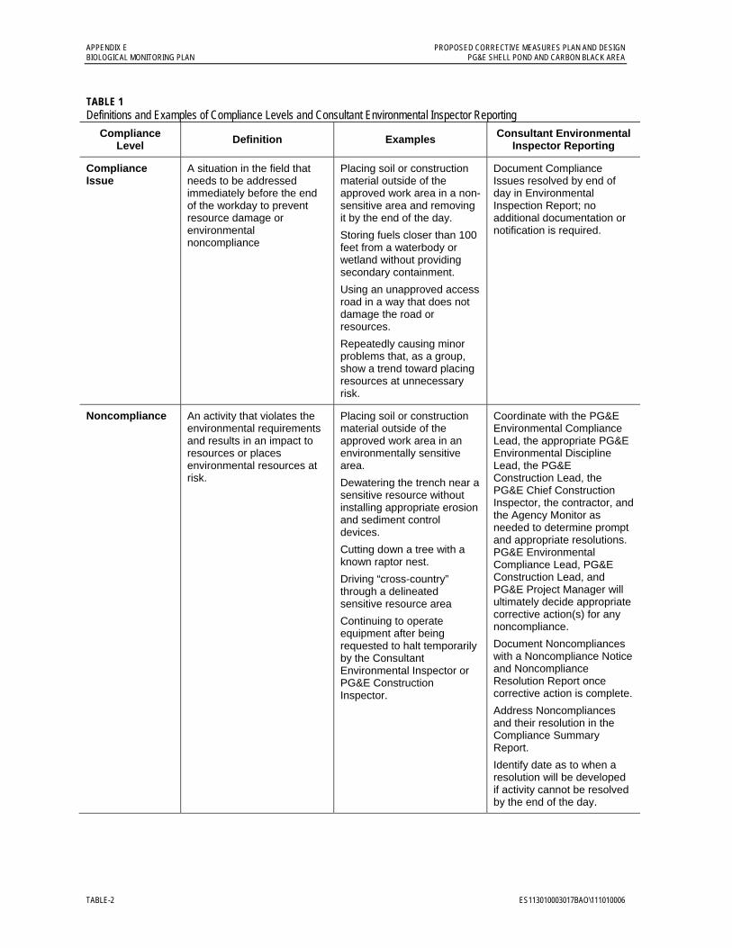
APPENDIX E PROPOSED CORRECTIVE MEASURES PLAN AND DESIGN BIOLOGICAL MONITORING PLAN PG&E SHELL POND AND CARBON BLACK AREA
TABLE-2 ES113010003017BAO\111010006
TABLE 1 Definitions and Examples of Compliance Levels and Consultant Environmental Inspector Reporting
Compliance Level
Definition Examples Consultant Environmental
Inspector Reporting
Compliance Issue
A situation in the field that needs to be addressed immediately before the end of the workday to prevent resource damage or environmental noncompliance
Placing soil or construction material outside of the approved work area in a non-sensitive area and removing it by the end of the day.
Storing fuels closer than 100 feet from a waterbody or wetland without providing secondary containment.
Using an unapproved access road in a way that does not damage the road or resources.
Repeatedly causing minor problems that, as a group, show a trend toward placing resources at unnecessary risk.
Document Compliance Issues resolved by end of day in Environmental Inspection Report; no additional documentation or notification is required.
Noncompliance An activity that violates the environmental requirements and results in an impact to resources or places environmental resources at risk.
Placing soil or construction material outside of the approved work area in an environmentally sensitive area.
Dewatering the trench near a sensitive resource without installing appropriate erosion and sediment control devices.
Cutting down a tree with a known raptor nest.
Driving “cross-country” through a delineated sensitive resource area
Continuing to operate equipment after being requested to halt temporarily by the Consultant Environmental Inspector or PG&E Construction Inspector.
Coordinate with the PG&E Environmental Compliance Lead, the appropriate PG&E Environmental Discipline Lead, the PG&E Construction Lead, the PG&E Chief Construction Inspector, the contractor, and the Agency Monitor as needed to determine prompt and appropriate resolutions. PG&E Environmental Compliance Lead, PG&E Construction Lead, and PG&E Project Manager will ultimately decide appropriate corrective action(s) for any noncompliance.
Document Noncompliances with a Noncompliance Notice and Noncompliance Resolution Report once corrective action is complete.
Address Noncompliances and their resolution in the Compliance Summary Report.
Identify date as to when a resolution will be developed if activity cannot be resolved by the end of the day.

Attachment 1 Project-Specific Environmental Compliance
Management Plan


PG&E PROJECT NAME ECMP 1
ATTACHMENT 1. Project-Specific Environmental Compliance Management Plan Prior to construction, the PG&E Environmental Compliance Lead will be responsible for completing this appendix with specific names and other project-specific details. Project Name: Construction Start Date: Role Name Phone Report Distribution
Environ. Inspection
Specialty Monitoring
Compl.
Summary
Noncompl. Notice
PG&E
Project Manager
Project Engineer
Construction Lead
Chief Construction Inspector
Construction Inspector(s)
PG&E Foreman
Environmental Compliance Lead
Public Affairs Liaison
News Representative
Attorney
Environmental Policy Contact
Regulatory Relations Contact
State & Local Government Relations Contact
PG&E Project Environmental Discipline Leads
Project Biologist
Project Archaeologist

PG&E PROJECT NAME ECMP 2
Role Name Phone Report Distribution
Environ. Inspection
Specialty Monitoring
Compl.
Summary
Noncompl. Notice
Project Geologist
Environmental Field Specialist
Environmental Scientist for Air Quality
Environmental Scientist for Water Quality
PG&E’s Environmental Consultant:
Environmental Compliance Supervisor
Lead Environmental Inspector
Environmental Inspector(s)
Biological Monitor(s)
Cultural Monitor(s)
Paleo Monitor(s)
SWPPP Inspector(s)
Contractor
Superintendent
Environmental Compliance Lead
Agency Monitors

PG&E PROJECT NAME ECMP 3
AGENCY PRIMARY POINTS OF CONTACT This table lists key agency contacts, as well as two PG&E employees who are designated as the primary and secondary point of contact for each agency. Agency Contact Primary PG&E Designated Point
of Contact Secondary PG&E Designated Point of Contact
Agency Name: Project Contact: Phone: Email:
Name: Phone: Email:
Name: Phone: Email:
Agency Name: Project Contact: Phone: Email:
Name: Phone: Email:
Name: Phone: Email:
Agency Name: Project Contact: Phone: Email:
Name: Phone: Email:
Name: Phone: Email:
Agency Name: Project Contact: Phone: Email:
Name: Phone: Email:
Name: Phone: Email:
Agency Name: Project Contact: Phone: Email:
Name: Phone: Email:
Name: Phone: Email:
Agency Name: Project Contact: Phone: Email:
Name: Phone: Email:
Name: Phone: Email:

PG&E PROJECT NAME ECMP 4
ENVIRONMENTAL COMPLIANCE MANAGEMENT PLAN DETAILS
PG&E’s Plan for Environmental Inspection and Specialty Monitoring Describe the frequency of environmental inspection, number of inspectors and/or monitors, locations where monitoring or inspection are required, etc. Agency Oversight and Inspection: Describe the CEQA lead agency’s oversight and inspection program, including whether or not Agency Monitors are authorized to approve extra workspace or other types of variances in the field. Meetings Describe the frequency of regular coordination and typical attendees. Compliance Inspection and Reporting
Environmental Inspection Report FORMS/DATABASE
Specialty Monitoring Report FORMS/DATABASE
Compliance Summary Report WEEKLY/BIWEEKLY/MONTHLY
Environmental Training Key Project Staff Environmental Training Date Held:
Duration (# of hours):

Attachment 2 Compliance Level Scenarios


PG&E Environmental Compliance Management Plan for Large-Scale Transmission Construction Projects 1
Attachment 2: Compliance Level Scenarios
Scenario Acceptable Incident Minor
Problem Compliance
Issue Non-Compliance
1. The contractor parked a backhoe on the right-of-way overnight. During the night the equipment leaked a large spot of oil on the ground. When the contractor discovered the leak in the morning, the crew cleaned up the spill properly and had a mechanic fix the equipment.
2. A hydraulic hose breaks on a backhoe and releases hydraulic fluid in a stream. The contractor cleans up the spill with absorbent pads and booms from the on-site spill kit and bags up the contaminated soil for disposal.
3. Same scenario as #2, but the contractor does not have spill response equipment on the site and someone has to drive 15 miles back to the yard to get some.
4. The Contractor is has just begun work on a wetland crossing and does not have spill response equipment onsite. You tell the on-site Construction Inspector it needs to be there and the contractor corrects the problem before the end of the day.
5. You are meeting with the Lead QA Inspector and the contractor in the field to talk through a dewatering operation that is scheduled for the following day. You remind the contractor to have extra hose on hand to deal with unexpected contingencies.
6. The contractor requests extra work space for spoil storage at a wetland crossing. The request is submitted to the CEQA lead agency, but the contractor begins using the area before the variance is approved.
7. The contractor begins excavation in a signed “Monitor Required” area without a paleontological resources monitor present.
8. The Contractor begins backfilling in a “Monitor Required” area without a cultural resources monitor present.
9. The grading crew uncovers buried bottles and fragments of stoneware. The required monitor is on-site at the time. All earthwork is ceased in the area of the find to allow the monitor time to make the necessary notifications and evaluate the discovery.

PG&E Environmental Compliance Management Plan for Large-Scale Transmission Construction Projects 2
Answers and Explanations
1. Incident. Hazardous material spills should be documented as incidents if they are cleaned up promptly and appropriately.
2. Incident. The fact that the spill occurred in a stream and may have resulted in contamination does not necessarily mean it is a compliance issue or a non-compliance. The spill would still need to get reported to the agencies, but the contractor has not done anything that is out of compliance with the environmental requirements.
3. Non-Compliance. While the same as the incident in #2, in this scenario the contractor was not incompliance with the project requirements, which likely worsened the impacts of the spill. Even though the spill may still be cleaned up before the end of the day, it would not be a compliance issue because the contractor’s failure to maintain response equipment on site exacerbated what would have otherwise been a routine incident.
4. Minor Problem. Since there has been no resource damage, this would be documented as a minor problem, as long as the contractor addressed it immediately (i.e., sent someone back to the yard to go get it). If they don’t have spill response equipment at the yard because the shipment did not arrive and there is none immediately available in the project area, it would be a Non-Compliance.
5. Acceptable. You should document that this meeting took place in your daily report because it involves planning ahead to prevent future compliance concerns. Entire this in the Site-Specific Observations section of the report.
6. Non-Compliance or Compliance Issue. This would typically be a non-compliance because the project is required to obtain agency approval to use extra workspace beyond what was initially approved. However, since the request had been submitted, it is likely that all necessary preconstruction surveys had been completed and there was no actual resource impact that resulted from premature use of the area. It could potentially be a compliance issue if it was a small amount of spoil, placed with no impact to resources, and it was removed before the end of the day.
7. Non-Compliance. This would be a non-compliance because the contractor placed sensitive resources at risk. Since there was a sign installed that was ignored, the activity boarders on blatant disregard for the environmental requirements. It could potentially be a compliance issue if there was no sign installed and the crew was unaware of the monitoring requirement when they started work, they only did very minor soil disturbance with no impact to fossils, and they immediately stopped work and waited to re-start until the monitor arrived.
8. Compliance Issue. Typically, monitoring is required for earthwork and backfilling is considered part of earthwork. However, because the trench spoils are already disturbed, if the contractor ceased backfilling until the monitor arrived, it would be a compliance issue rather than a non-compliance (i.e., addressed immediately and no impact to resources). Depending on how the actual mitigation measure reads, this may be acceptable (i.e., if backfilling is not an activity that requires monitoring). If backfilling requires monitoring and this is the second time this particular crew has started backfilling without a monitor present, it would likely be a non-compliance.
9. Incident. It is not a violation of the environmental requirements to uncover buried cultural materials, so long as the discovery is handled appropriately.

Attachment 3 Environmental Inspection Report Form


ENVIRONMENTAL INSPECTION REPORT
Project Name: Inspector Name: Date: Weather: Report #1: -
Daily Summary Include a brief explanation for any YES answers in the Notes 1. Were there any notable compliance concerns today? (If yes, please check as many as apply) YES NO
INCIDENT MINOR PROBLEM COMPLIANCE ISSUE NONCOMPLIANCE
2. Were any photographs taken today? YES NO
3. Were any new personnel trained today? (If YES, include number trained in Notes) YES NO 4. Were any specialty monitors on the site today? (If YES, include type of monitor and name in Notes) YES NO 5. Did any agency personnel visit the site today? (If YES, include agency and staff name in Notes) YES NO
6. Were any agency notifications required today? YES NO 7. Were any potential paleontological or cultural materials identified? YES NO 8. Did the project have any unanticipated or unpermitted adverse impacts today? YES NO 9. Was the project shutdown for any reason today? YES NO
10. Did anyone from the public inquire or comment about the project? YES NO 11. Are there any outstanding follow-up items from previous reports that have not been completed?
YES NO
Notes:
General Requirements Based on the activities you observed today, please answer the following questions. If there is a compliance concern for any of these general requirements, please fill out a site-specific observation with the details:
1. Were the right-of-way boundaries sufficiently marked by staking, flagging, and exclusion fencing? YES NO NA
2. Did all vehicles and personnel stay in approved work areas? YES NO NA 3. Were vehicle speed limits observed? YES NO NA 4. Was the job site kept free of litter? YES NO NA 5. Were waste management receptacles filled at or beyond capacity? YES NO NA
6. Did crews use approved access roads? YES NO NA
7. Did you observe any pets or firearms on the job site? YES NO NA
8. Were all paved areas free of visible sediment tracking or other particulate matter? YES NO NA
9. Were erosion and sediment control measures installed according to the project requirements? YES NO NA
10. Were spill-response materials readily available for all crews? YES NO NA
11. Was refueling conducted in appropriate areas with containment and spill-response materials? YES NO NA
12. Were hazardous materials stored and handled properly? YES NO NA
13. Did construction sediment or hazardous materials make contact with water resources today?
YES NO NA
14. Was appropriate secondary containment for store hazardous materials used onsite? YES NO NA
Notes:
1 Each inspector will be assigned a two‐digit number and the report number is the date and the inspector number (e.g., 071210‐03)

SITE-SPECIFIC OBSERVATIONS #1 Activity: General Location (e.g., Francis Creek): Specific Location (e.g., MP, STN, POLE): Compliance Level: ACCEPTABLE INCIDENT MINOR PROBLEM COMPLIANCE ISSUE NONCOMPLIANCE
Follow-up Required? NO YES (If yes, specify): Notes:
#2 Activity: General Location (e.g., Francis Creek): Specific Location (e.g., MP, STN, POLE): Compliance Level: ACCEPTABLE INCIDENT MINOR PROBLEM COMPLIANCE ISSUE NONCOMPLIANCE Follow-up Required? NO YES (If yes, specify): Notes:
#3 Activity: General Location (e.g., Francis Creek): Specific Location (e.g., MP, STN, POLE): Compliance Level: ACCEPTABLE INCIDENT MINOR PROBLEM COMPLIANCE ISSUE NONCOMPLIANCE
Follow-up Required? NO YES (If yes, specify): Notes:
#4 Activity: General Location (e.g., Francis Creek): Specific Location (e.g., MP, STN, POLE): Compliance Level: ACCEPTABLE INCIDENT MINOR PROBLEM COMPLIANCE ISSUE NONCOMPLIANCE
Follow-up Required? NO YES (If yes, specify): Notes:
#5 Activity: General Location (e.g., Francis Creek): Specific Location (e.g., MP, STN, POLE): Compliance Level: ACCEPTABLE INCIDENT MINOR PROBLEM COMPLIANCE ISSUE NONCOMPLIANCE
Follow-up Required? NO YES (If yes, specify): Notes:
#6 Activity: General Location (e.g., Francis Creek): Specific Location (e.g., MP, STN, POLE): Compliance Level: ACCEPTABLE INCIDENT MINOR PROBLEM COMPLIANCE ISSUE NONCOMPLIANCE
Follow-up Required? NO YES (If yes, specify): Notes:
#7 Activity: General Location (e.g., Francis Creek): Specific Location (e.g., MP, STN, POLE): Compliance Level: ACCEPTABLE INCIDENT MINOR PROBLEM COMPLIANCE ISSUE NONCOMPLIANCE
Follow-up Required? NO YES (If yes, specify): Notes:

Attachment 4 Specialty Monitoring Report Form


SPECIALTY MONITORING REPORT1
Project Name: Monitor Name: Date: Weather: Report #2: - Other Relevant Ambient Conditions: Type of Monitoring: BIOLOGICAL CULTURAL PALEONTOLOGICAL OTHER (Specify)
General Location(s) (e.g., Francis Creek): Specific Location (e.g., MP, STN, POLE): Activities Monitored: Monitoring Required By (check as many as apply):
MITIGATION MEASURE PLAN/PROCEDURE SPECIFICATION DRAWING PERMIT CONDITION OTHER
Specify Source (e.g., Mitigation Measure BIO-6):
Daily Summary Include a brief explanation for any YES answers in the Notes 1. Did you perform any surveys today? YES NO 2. Did you observe any sensitive resources in the work area today? YES NO 3. Were any photographs taken today? YES NO 4. Were any other specialty monitors on the site today? YES NO
(If YES, include type of monitor and name in Notes) 5. Did any agency personnel visit the site today? YES NO
(If YES, include agency and staff name in Notes) 6. Were any potential paleontological or cultural materials identified? YES NO 7. Did work activities conform to the project’s resource-protection requirements in your discipline area?
YES NO 8. Did the project have any unanticipated or unpermitted adverse resource impacts today? YES NO 9. Was the project shutdown for any reason today? YES NO 10. Are there any outstanding follow-up items from previous reports that have not been completed?
YES NO Notes:
1 If the same individual is functioning as both an Environmental Inspector and a Specialty Monitor (e.g., Biological Monitor), he or she should use the Environmental Inspection Report only. In these cases, surveys and species sightings would be documented in the “Site‐Specific Observations” section.
2 Each monitor will be assigned a two‐digit number. The report number is the date and the monitor number (e.g., 071210‐03)


Attachment 5 Noncompliance Notice Form


NONCOMPLIANCE NOTICE
Project Name: _____________________________________________ Contractor: ____________________________
Date: _______________________________________ Report #: NN-________________________________________
Landowner: __________________________________ Parcel Number: _____________________________________
General Location(s) (e.g., Francis Creek): _____________________________________________________________
Specific Location(s) (e.g., MP, STN, POLE): ___________________________________________________________
Identified By: _____________________________________________________________________________________
Verbal Notification? Notification Date:_____________ Individual Notified:____________________
Noncompliance Source: (check as many as apply)
Specify Source (e.g. Mitigation Measure BIO-6): _______________________________________________________
Did the noncompliance result in resource damage?
Has the same contractor had other related compliance concerns on the project?
Related NN#___________________________
DESCRIPTION: (Include a detailed description, including information on any resources damaged. Attach additional sheets if necessary.)
CORRECTIVE ACTION REQUIRED: DEADLINE FOR CORRECTIVE ACTION: _______________(Attach additional sheets if necessary.)
SIGNATURES:
PG&E Environmental Compliance Lead:
Name: _____________________________ Signature: ___________________________ Date: __________________
PG&E Construction Lead:
Name: _____________________________ Signature: ___________________________ Date: __________________
Contractor Superintendant:
Name: _____________________________ Signature: ___________________________ Date: __________________
mitigation measure c plan/procedure c specification c regulatory requirement c drawing c permit condition c other c
yes c no c
yes c no c
yes c no c
yes c no c


Attachment 6 Noncompliance Resolution Report Form


NONCOMPLIANCE RESOLUTION REPORT
Project Name: _____________________________________________ Contractor: ____________________________
Date: __________________________ Noncompliance Report #: NN-_______________________________________
CORRECTIVE ACTION COMPLETED: DATE COMPLETED: ___________________________
(Describe corrective actions completed.)
AGENCY NOTIFICATIONS COMPLETED
Agency Name Agency Representative Date Contacted Contacted By Follow Up Required?
1.
2.
3.
4.
5.
6.
7.
8.
Notes:
SIGNATURES:
PG&E Environmental Compliance Lead:
Name: _____________________________ Signature: ___________________________ Date: __________________
PG&E Construction Lead:
Name: _____________________________ Signature: ___________________________ Date: __________________
Contractor Superintendant:
Name: _____________________________ Signature: ___________________________ Date: __________________
yes c no c


Attachment 7 Sample Compliance Summary Report


[INSERT PROJECT NAME] Compliance Summary Report Page 1
[INSERT PROJECT NAME] Compliance Summary Report [INSERT REPORTING PERIOD] To use this template, delete instructions in italics and replace with report text.
Introduction
This compliance summary report is intended to summarize the status of the project’s compliance with environmental permit conditions, mitigation measures, and regulatory requirements during the reporting period. It also provides an overview of sensitive species sightings and observations, environmental trainings conducted, and any complaints received from the public.
Construction Status
Provide a brief overview of key construction milestones achieved during the reporting period to provide some context for reviewers.
Environmental Inspection and Specialty Monitoring Summary
List the names and companies of Environmental Inspectors and Specialty Monitors who inspected/monitored construction activities during the reporting period.
Summary of Environmental Compliance Activities and Significant Environmental Events
Drawing from the daily reports prepared by the environmental team, summarize key environmental compliance activities and significant environmental events. This section is primarily used to summarize acceptable activities. Compliance concerns and incidents are summarized in a subsequent section.
Project Photographs
Insert two to three photographs with captions that depict key activities/events during the reporting period.
Summary of Noncompliances, Compliance Issues, Minor Problems, and Incidents
Information for this section may be presented in a table or a narrative as long as all the pertinent information is included.

[INSERT PROJECT NAME] Compliance Summary Report Page 2
Date Report No. Location Description Date Resolved
Resolution
Noncompliance Compliance Issue Minor Problem Incident
Summary of Variances and Extra Work Space Requests
Variance or EWS Request Number
Date Submitted
Summary of Request Approval Status
Summary of Public Complaints
Name Date Summary of Compliant Resolution
Outstanding/Follow‐Up Items
Attachment 8 Sample Supervisor Training Agenda and
Training Attendance Log


ENVIRONMENTAL TRAINING SIGN-IN SHEET
Project: _____________________________ Trainer: ______________________________ Date: __________________
Type of Training: c Key Project Staff c General Crew Training c Tailboard Training
PLEASE NOTE:By signing below, I acknowledge that I have attended the above-referenced environmental training,
and I agree to comply with all the environmental requirements presented.
Name (print) Name (signature) Company/Role
1.
2.
3.
4.
5.
6.
7.
8.
9.
10.
11.
12.
13.
14.
15.
16.
17.
18.
19.
20.
21.
22.
23.
24.
25.


Attachment 9 Temporary Extra Workspace Request Form


TEMPORARY EXTRA WORK SPACE REQUEST FORM
__________________________________________________________________________________________________Project Name Request No
__________________________________________________________________________________________________Location/Address City/County
__________________________________________________________________________________________________Size/dimensions
__________________________________________________________________________________________________Proposed Use of Site
__________________________________________________________________________________________________Proposed Date(s) of Use Proposed Hours of Use
__________________________________________________________________________________________________Current Vegetative Cover/Land Use Adjacent Land Uses
__________________________________________________________________________________________________Request Prepared By Date Submitted
*Any “Yes” answers in the following checklist need to be explained in an attached sheet.
GENERAL CONSIDERATIONS YES* NO CEQA Lead Agency
Duration of Use – Would the site be used for more than 30 days?
Air Quality - Would equipment be on-site or idle for more than 10 minutes? Would there be dust-producing activities?
Cultural Resources – Would clearing or grading be required?
Water Resources – Would runoff from the site flow into storm drains or a waterway? Would equipment refueling or maintenance be performed? Would materials block/impact storm drains or gutters?
Land Use and Recreation – Would use of site block access to local land uses and recreational areas?
Noise – Are noise-sensitive receptors (E.G., schools, hospitals, churches, convalescent homes, parks, recreational areas) adjacent to the site?
Socioeconomic - Would access to business be blocked? Would there be disruption of business operations?
Traffic – Would parking be eliminated? Would increased construction traffic cause impacts? Is the site a residential area?
Visual – Would lights at site create glare for adjacent land uses (including roadways).

Standard Conditions of Approval:
• TheCEQALeadAgency,viaitsdesignatedEnvironmentalMonitor,willreviewandapprove/deny the requests within four business days of receiving this completed form.
• Useoftemporaryextraworkspaceshallbeincompliancewithlocalordinances(includingtraffic/noise) and mitigation measures.
• Ifanysignsofculturalresourcesareidentified,workshallceaseimmediatelyandthesiteshall be re-evaluated.
• Theproposedsiteshallnotbeusedforstorageoffuelorhazardousmaterials.
• Alldrips,leaks,and/orspillsfromvehiclesand/orequipmentshallbecleaned-upimmediately and disposed of in appropriate labeled containers.
• Adjacentstreetsshallbesweptorcleanedwithwaterattheendoreachworkdayifvisiblesoilmaterial is carried on them.
• Noparkingorstorageofvehicles(includingpersonalvehicles),equipment,pipe,oranyotherproject related item shall be allowed on adjacent roadways.
• Ifacomplaintisreceived,itshallbeforwardedtothePG&EEnvironmentalComplianceLead andtheCEQALeadAgencyEnvironmentalMonitorforreview.
Thefollowingsignaturesindicatethattheproposedtemporaryextraworkspaceisapprovedforusebytheproject.Onarandombasis,aCEQALeadAgencyEnvironmentalMonitorwillverifythatuseoftheproposedsiteisinaccordancewiththeconditionsnoted.Thisapprovalmayberevokedatanytimebyanyoneoftheapproval team. Failure to comply with all conditions will result in immediate revocation of this approval.
__________________________________________________________________________________________________Property Owner Date
__________________________________________________________________________________________________Construction Lead Date
__________________________________________________________________________________________________Environmental Inspector Date
TheaboveTEWSrequestandattacheddocumentationhavebeenreviewedandthisrequestis:
APPROVED / DENIED (circle one)
__________________________________________________________________________________________________CEQALeadAgencyEnvironmentalMonitor Date
AdditionalCEQALeadAgencyConditionsofApproval:
__________________________________________________________________________________________________
__________________________________________________________________________________________________
__________________________________________________________________________________________________
__________________________________________________________________________________________________
__________________________________________________________________________________________________
(CEQA Lead Agency Lead Monitor Initial______)

Attachment 10 Environmental Variance Request Form


ENVIRONMENTAL VARIANCE REQUEST FORM
Project Name: ________________________________ Request Prepared By: ________________________________
Date Approval Required: ______________________ Variance Request No: ________________________________
Date Submitted: ______________________________ Location: ___________________________________________
Landowner: __________________________________ Landowner Parcel Number: ___________________________
Current Vegetative Cover/Land Use: _________________________ Existing Sensitive Resource?
If yes, specify sensitive resource: ____________________________________________________________________
Variance From: (check as many as apply):
Specify Source (e.g. Mitigation Measure B.5): _________________________________________________________
Detailed Description of Variance and Justification: Attachments? Photos?
(Attach additional information if needed)
Resources:
Biological
Previous Biological Survey Reference: ______________________________________________________________
Cultural
Previous Cultural Survey Report Reference: _________________________________________________________
mitigation measure c plan/procedure c specification c drawing c permit condition c other c
c no resources present c resources present cn/a
c no resources present c resources present within project ape: yes c no ccn/a (paved/gravel area and no ground disturbance)
yes c no c
yes c no c yes c no c

Conditions of Approval or Reasons for Denial (Attach additional information if needed)
PG&E Required Signatures:
PG&E Chief Construction Inspector or PG&E Foreman:
Name: _____________________________ Signature: ___________________________ Date: __________________
Environmental Inspector:
Name: _____________________________ Signature: ___________________________ Date: __________________
PG&E Environmental Compliance Lead:
Name: _____________________________ Signature: ___________________________ Date: __________________
CEQA Lead Agency Required Signatures for Approval: (if applicable)
Name: _____________________________ Signature: ___________________________ Date: __________________
Potential Impacts: (Describe and attach additional information if needed)
Impacts Adequately Addressed in CEQA Document?
c variance is needed for safe and efficient construction
c approved c approved with conditions c denied (see conditions above)
c approved c approved with conditions (see conditions above) c denied
c field review complete
yes c no c n/a c

Appendix F Air Quality Management Plan


A p p e n d i x F
Air Quality Management Plan
PG&E Shell Pond and Carbon Black Area,
Bay Point, California
Prepared for
Pacific Gas and Electric Company
April 2011
155 Grand Avenue, Suite 800
Oakland, CA 94612


ES113010003017BAO\111010007 iii
Contents
1.0 Air Quality Management Plan .................................................................................. 1-1 1.1 Introduction ...................................................................................................... 1-1 1.2 Compounds of Concern ................................................................................. 1-2 1.3 Air Quality Management Plan ...................................................................... 1-2 1.4 References ......................................................................................................... 1-6
Figures 1 Annual Wind Rose for the Pittsburg Power Plant for Years 2002 to 2005 2 Shell Pond Air Management and Monitoring Plan Sampling Locations
Tables 1 Maximum COC Analytical Results for NNM and Surface Water Samples 2 Summary of COCs Monitored Instrumentation, Monitoring Frequency, and
Calibrations


ES113010003017BAO\\111010007 1-1
1.0 Air Quality Management Plan
1.1 Introduction During remediation of the PG&E Shell Pond, there is the possibility that compounds may be released into the air during non-native material removal activities. These compounds include volatile organic compounds (VOCs), fugitive dust, odors as hydrogen sulfide (H2S) and methyl-mercaptan, combustion exhaust (construction equipment and other vehicles), and portland cement. These compounds may be released during excavation of non-native materials (NNM), vehicle use, and site construction activities. The compounds of concern (COC) were identified during site characterization activities performed for PG&E by CH2M HILL (2010) and this Plan describes the monitoring procedures to be implemented during the PG&E Shell Pond remediation effort.
This Plan does not addresses site workers safety issues as they are addressed in a separate Health and Safety Plan included as Appendix G of the Proposed Corrective Measures Plan and Design (PCMPD).
1.1.1 Local Climate The PG&E Shell Pond site lies along the San Joaquin River within a lowland area that is influenced by wind flow through the Carquinez Strait. The prevailing winds at the project site blow in a westerly direction through the Strait. During the summer and fall months, offshore high pressures coupled with low pressure in the Central Valley (of California) results in marine air flowing eastward through the Carquinez Strait, with afternoon wind speeds of 15 to 20 mph being common and annual average wind speeds of approximately 9 to 10 mph east of Martinez (Bay Area Air Quality Management District, 2010). Figure 1 presents an annual wind profile from the Pittsburg Power Plant (located approximately 3 miles due east) that shows winds at the PG&E Shell Pond site are predominately out of a westerly direction.
1.1.2 Potential Sources of Air Emissions Several site activities to be conducted during the corrective action have the potential to create dust emissions:
Site Preparation – temporary road and material-handling area construction including grading, backfilling, and other site preparation activities involving earthwork may produce fugitive dust, COCs, odors, and vehicle exhaust emissions.
Excavation (mechanical and hydraulic) of NNM from the pond may produce fugitive dust, COCs, odors, and vehicle exhaust emissions. Mechanically excavated NNM may require the addition of portland cement to reduce material moisture content sufficiently for transport to the landfill. The addition of portland cement may result in fugitive cement dust emissions. Excavation of NNM has the potential to release odors which will be controlled with odor suppressants.

APPENDIX F PROPOSED CORRECTIVE MEASURES PLAN AND DESIGN AIR QUALITY MANAGEMENT PLAN PG&E SHELL POND AND CARBON BLACK AREA
1-2 ES113010003017BAO\\111010007
Loading and Unloading – Loading and unloading of trucks with excavated NNM has a slight possibility to generate dust because the material will be damp. No stockpiling of NNM is expected. However, if a stockpile is created, it will either be maintained in a damp condition or will be covered consistent with best management practices.
Vehicular Traffic – Movement of construction/excavation equipment around the site area is capable of creating fugitive dust and vehicle exhaust emissions in excavated or cleared areas. The potential also exists for vehicular traffic on paved or unpaved roads and parking areas near or in the construction area to produce dust and vehicle exhaust emissions.
Placing soil cover for reseeding on the Carbon Black Area may produce fugitive dust and vehicle exhaust emissions.
1.2 Compounds of Concern Field investigations and analytical results for NNM within the PG&E Shell Pond (CH2M HILL, 2010; ENTRIX, 2009) indicated that although the material does not meet criteria to be classified as a hazardous waste, it contains elevated concentrations of numerous COCs. Table 1 presents a summary of the COCs and the maximum analytical results for samples taken of the NNM and surface waters (tables are located at the end of this appendix). Concentrations of these contaminants are orders of magnitude lower in the underlying native media and are generally less than or equal to the low range Ecological Preliminary Remediation Goals (EcoPRGs ) for constituents with screening criteria. Based on existing analytical results, the NNM meets acceptance criteria and is not considered a hazardous waste. The NNM will be transported for disposal at the Keller Canyon in Contra Costa County.
Odors have been observed when NNM in the PG&E Shell Pond is exposed to the atmosphere such as when it is sampled and taken out of the pond or when portions of the pond are not covered by the water cap. A previous ambient monitoring effort, performed in August 2008, identified the following potential odor causing compounds: carboxylic acids, amines, reduced sulfur compounds, VOCs, ammonia, and petroleum hydrocarbons. The result of the August 2008 monitoring determined that H2S and methyl mercaptan were detected above the odor detection threshold. Certain VOCs and petroleum hydrocarbons were detected at significantly higher concentrations downwind of the pond compared to upwind concentrations.
Due to the nature of the contamination (saturated soils), previous analytical results for NNM and surface water, and the remediation actions being considered at the PG&E Shell Pond, the potential for release of COCs is very low. However, air monitoring is planned to ensure workers and the public are protected.
1.3 Air Quality Management Plan The site Construction Superintendent (or his designee) will be responsible for implementing the air monitoring program. Air monitoring will be conducted for fugitive dust as particulate matter with an aerodynamic diameter of 10 microns (PM10), VOCs, and H2S. Figure 2 shows the approximate locations where sampling will be performed. Although

PROPOSED CORRECTIVE MEASURES PLAN AND DESIGN APPENDIX F PG&E SHELL POND AND CARBON BLACK AREA AIR QUALITY MANAGEMENT PLAN
ES113010003017BAO\\111010007 1-3
unlikely due to the prevailing winds being consistently from a westerly direction, sampling locations may move slightly to maintain an upwind downwind orientation to the sampling systems. A discussion of the monitoring methodology, action levels, and mitigation measures is presented below. Table 2 presents a summary of the COC to be monitored, monitoring frequency, and calibrations schedule.
1.3.1 Fugitive Dust and Particulate Matter Monitoring Air monitoring of particulate matter will be performed using both a hand held particulate detector and continuous sampling system.
Three continuous PM10 sampling systems, based on the Beta Ray Attenuation Monitoring (BAM) technology (Met One Instruments Model BAM-1020, E-BAM, or equivalent), will continuously measure PM concentrations by drawing a known volume of ambient air into the monitor through an inlet (via a vacuum pump). Particles are deposited on a filter where a Carbon-14 element emits beta rays through the filter and particles. A scintillation detector detects and counts the beta rays which are then correlated to mass of particles on the filter. Using the known sample volume, the BAM calculates the concentration of particulate matter in the ambient air. The BAM sampling methodology will conform to USEPA reference method contained in Title 40, Code of Federal Regulations (CFR), Part 50, (described in Appendix G of the PCMPD). The three monitors will be located along the fenceline in an upwind/downwind orientation, with 2 of the monitors located downwind. These monitors will be operated continuously during the remediation effort.
A handheld particulate detector will also be used designed to detect concentrations of airborne PM10 using a DataRAM (or equivalent). The hand-held PM monitor passes infrared light through a sample of ambient air and correlates the amount of light scatter to the concentration of particulate matter. The hand-held PM monitor will be able to detect Total Suspended Particulates and PM10 particulate matter concentrations. The handheld monitors will be operated throughout the work site on a periodic basis (at least once per hour) during each work day during remediation.
Fugitive Dust Action Levels The California Ambient Air Quality Standard (AAQS) for PM10 is 0.05 milligrams per cubic meter (mg/m3) based on a 24-hour average. As site work is expected to occur for 8 hours per day, an action level of 0.11 mg/m3 was selected as a level to demonstrate compliance with California 24-hour average AAQS for PM10 of 0.05 mg/m3. The fugitive dust mitigation measures specified in the next section are designed to eliminate offsite fugitive dust impacts. However, if fugitive dust monitoring demonstrates that the action level is exceeded, the Construction Superintendent (or his designee) shall review sources of fugitive dust and modify the mitigation measures to reduce fugitive dust emissions, and additional handheld fugitive dust monitoring shall be performed to demonstrate the effectiveness of the modified mitigation measures. If sufficient reductions in fugitive dust emissions cannot be effected to reduce monitored fugitive dust concentrations below the action level, work activities will be suspended until monitoring results are below the action level.
Fugitive Dust Mitigation Measures All visible dust will be controlled using water spray. Water may be obtained either from the eastern slough, the Contra Costa Water District (which has an access valve on site), or other

APPENDIX F PROPOSED CORRECTIVE MEASURES PLAN AND DESIGN AIR QUALITY MANAGEMENT PLAN PG&E SHELL POND AND CARBON BLACK AREA
1-4 ES113010003017BAO\\111010007
sources. Water will be applied by large-diameter spray hose and water truck to the work areas and roads to control visible dust, but not to the level where runoff is generated.
Construction Traffic Fugitive dust emissions from construction traffic traveling on unpaved surfaces will be controlled as needed using one or more of the following methods:
1. Applying a chemical stabilizer to unpaved roads.
2. Watering unpaved roads at least once every 2 hours if wind conditions reach 15 miles per hour.
3. Track-out of loose materials to public paved roads will be controlled using gravel access aprons at all motor vehicle access points from paved roads to the project site. Speed limit signs will be posted at the entrance to the project site. The posted speed limit onsite will be 15 miles per hour.
Any equipment that has been inside the project site will go through a tire cleaning process before leaving the site to reduce dust and minimize the potential to spread contaminants.
In addition, the following measures shall be addressed for the transportation of NNM to the landfill:
Covering haulage trucks to stop dust and odor emissions Wetting material, if needed, prior to loading vehicles Ensuring appropriate freeboard of material in the vehicles
Construction employees will be instructed to use a designated area for parking.
Site Preparation and Foundation Work Fugitive dust emissions from site preparation work will be controlled using the following methods. All methods should be applied without generating surface-water runoff.
1. For earth-moving activity, maintain soil moisture content sufficient to minimize fugitive dust creation. For construction fill areas which have an optimum moisture content for compaction, completion of the compaction process will be performed as expeditiously as possible to minimize fugitive dust.
2. For disturbed surface areas, apply dust suppression in sufficient quantity and frequency to maintain a stabilized surface, and according to manufacturer’s specifications. Any areas which cannot be stabilized, as evidenced by wind-driven dust, must have an application of water at least twice per day to at least 80 percent of the unstabilized area.
3. During high wind events (i.e., wind conditions exceeding 25 mph), earth-moving activities will cease or water will be applied to soil not more than 15 minutes prior to moving such soil.
4. On the last day of active operations prior to a weekend, holiday, or any other period when active operations will not occur for more than four consecutive days: apply water with a mixture of chemical stabilizer diluted to not less than 1/20 of the concentration required to maintain a stabilized surface for a period of six months.

PROPOSED CORRECTIVE MEASURES PLAN AND DESIGN APPENDIX F PG&E SHELL POND AND CARBON BLACK AREA AIR QUALITY MANAGEMENT PLAN
ES113010003017BAO\\111010007 1-5
Excavation Activities Excavation activities will be visually monitored daily for the generation of fugitive dust and in accordance with the Health and Safety Plan’s air monitoring requirements (Appendix G of the PCMPD). If dust is being generated, water will be applied to the point of excavation to control dust without generating runoff. In the event of wind speeds exceeding 25 miles per hour, water will be applied to soil not more than 15 minutes prior to moving soil, or construction activities will be halted.
Loading and Unloading Activities Dust production will be avoided during loading and unloading operations by the use of water spray. Materials that must be excavated and loaded using conventional methods will be monitored closely for dust creation. Possible techniques for controlling dust during vehicle loading and unloading include application of water or chemical dust suppressants, covering partially filled vehicles as filling occurs, reducing the speed at which loading and unloading activities occur, and using containers for loading and unloading vehicles.
Material Stockpiles Fugitive dust emissions from storage piles will be controlled by using a temporary cover or a chemical dust control agent to stabilize the piles.
Grading Prior to completion of grading, water will be applied sparingly to any disturbed areas as needed to prevent visible dust emissions. Care will be taken to avoid creating runoff. Graded areas will be stabilized with chemical stabilizers within 5 working days of grading completion.
1.3.2 Volatile Organic Compound Monitoring Air monitoring of VOCs and petroleum hydrocarbons will be performed using a handheld photoionization detector (PID) capable of detecting concentrations as low as 0.1 part per million (ppm) (MultiRAE Plus with a 10.6 eV lamp or equivalent). The handheld PID uses a lamp to ionize organic compounds present in the ambient air, including total petroleum hydrocarbons (TPH) and organic decomposition by-products such as methane. The instrument then measures ionization potential to determine the ambient concentration of the organic compounds. The handheld monitor will be operated throughout the work site on a periodic basis (at least once per hour at the upwind and downwind sampling locations) during each work day during remediation.
Volatile Organic Compound Action Levels A VOC action level of 1 ppm (measured as the difference between upwind and downwind sampling) was selected as previous field sampling determined that neither the NNM nor surface waters contained measureable levels of VOCs. If the action level is exceeded based on monitoring, the Construction Superintendent (or his designee) shall review sources of VOC emissions and determine appropriate mitigation measures (such as reducing the area of exposed NNM). If sufficient reductions in VOC emissions cannot be effected to reduce monitored VOC concentrations below the action level, work activities will be suspended until monitoring results comply with the action level.

APPENDIX F PROPOSED CORRECTIVE MEASURES PLAN AND DESIGN AIR QUALITY MANAGEMENT PLAN PG&E SHELL POND AND CARBON BLACK AREA
1-6 ES113010003017BAO\\111010007
1.3.3 Hydrogen Sulfide Monitoring The monitoring of reduced sulfur compounds (mercaptans and H2S) will be performed using a handheld detector (GEM 2000 or equivalent) capable of detecting H2S concentrations as low as 1 ppm. The H2S monitor uses an electrochemical cell to detect H2S concentrations in the ambient air. H2S will be used as a surrogate for all reduced sulfur compounds.
Sampling will occur along the project boundary at locations both upwind downwind of the project activities depending on observed wind conditions. Two monitors will be placed at the fenceline in the downwind direction to measure odors and one monitor will be placed upwind of the excavation to measure ambient odor concentrations resulting from biogenic sources. Odor monitoring will be conducted hourly during mechanical NNM removal activities, every 8 hours during hydraulic NNM removal activities and every 12 hours when only dewatering, and loading for offsite transport is conducted. A wind sock or similar device will be installed at the project site assist in determining the appropriate upwind and downwind sampling locations.
Hydrogen Sulfide Action Level The proposed H2S action level for implementing additional odor mitigation measures is 1 ppm measured as the difference of upwind and downwind concentrations. In the event that the action level is exceeded, the mitigation measures described in the next subsection shall be implemented.
H2S Mitigation Measures Activities that expose NNM to the atmosphere have the potential to generate H2S emissions, resulting in H2S odors. Should odors or odor-causing compounds be detected above the action level, SL-6000 will be used for mitigation. SL-6000 at a dilution ratio of 1000:1 was found to be effective in suppressing odors from PG&E Shell Pond NNM during sampling activities. It may deployed either by direct spray application to exposed NNM or NNM in geotextile tubes, or in conjunction with a misting system installed downwind of the NNM handling areas. If H2S monitoring or qualitative observations by onsite workers or offsite observers indicate increased odor suppression is needed, the dilution ratio may be lowered to 500:1 or 250:1.
1.4 References Bay Area Air Quality Management District (BAAQMD). 2010.Californi Environmental
Quality Act, Air Quality Guidelines.
CH2M HILL. 2010. Summary of Findings Associated with Shell Pond Field Surveys. PG&E Shell Pond, Bay Point, California. July.
ENTRIX. 2008. Technical Memorandum: Dust and Odor Monitoring PG&E Shell Pond Site, Bay Point, CA

Figures


ES032411184221BAO ConceptSection_LeveeBreach.ai 03-30-11 dash
FIGURE 1 Annual Windrose for the Pittsburg Power PlantPG&E Shell Pond and Carbon Black Area ProjectBay Point, California
Annual wind rose for Pittsburg Onsite Meteorological Station Data taken from 2002-2005 for all months.
Displays wind speed, direction (blowing from)
Station ID: 72493 Run ID: Year: 2002 2003 2004 2005 Date Range: Jan 1 - 31-Dec ANNUAL
J2-1


VICINITY MAP
!(
Shell Pond
Carbon BlackArea
McAvoy Harbor
Shell ChemicalPlant
Mc
Av
oy
Rd
Port Chicago Hwy
N B
roa
dw
ay
Av
e
Suisun Ave
Stake Point
SUISUN BAY
0 800 1,600400
Feet
LEGEND
!(
$
ES032411184221BAO Fig_2_air_monitoring_locations.ai 04-04-11 dash
Upland Ditch
Project Boundary
Carbon Black Area Boundary
Influent Point From Upland Ditch
Union Pacific Railroad/Burlington Northern Santa Fe Railway/Sacramento Northern Railroad
Union Pacific Railroad/Burlington Northern Santa Fe Railway/Sacramento Northern Railroad
Union Pacific Railroad/Burlington Northern Santa Fe Railway/Sacramento Northern Railroad
FormerHarris Yacht Harbor
FormerHarris Yacht Harbor
FIGURE 2 Air Monitoring LocationsPG&E Shell Pond and Carbon Black Area ProjectBay Point, California
West ParcelWest ParcelWest Parcel
Upland DitchUpland Ditch
SHELL P ND PARCEL
EAST PARCELAPN: 096-100-020
EAST PARCEL (SOUTH)
APN: 096-100-020
APN 09 -260 001O
8 -:
WEST PARCELAPN: 098-250-013
SHELL PAPN: OND P 098-260ARC-003
EL (SOHUT )
Shell Pond Parcel 098-260-001
East Parcel 096-100-020
East Parcel (South) 096-100-020
West Parcel 098-250-013
Air monitoring locations during NNM removal from pond
Air monitoring locations during dewatering and loading for transport
Shell Pond Parcel (South) 098-260-003
Project ParcelsUpwind Air
Monitoring LocationDownwind Air
Monitoring Location
Downwind Air Monitoring Location
Downwind Air and Meteorological
Monitoring Location


Tables


PROPOSED CORRECTIVE MEASURES PLAN AND DESIGN APPENDIX F PG&E SHELL POND AND CARBON BLACK AREA AIR QUALITY MANAGEMENT PLAN
ES113010003017BAO\111010007 TABLES-1
TABLE 1 Maximum COC Analytical Results for NNM and Surface Water Samples PG&E Shell Pond and Carbon Black Area, Bay Point, California
Contaminant Location and Maximum Concentration
(mg/kg for SS; mg/L for SW)
PAH-anthracene SS: 81
SW: 0.000086
PAH-benzo(a)pyrene SS: 71
SW: 0.0013
Carbon black Potential
Chromium (as Cr(II) & Cr(III) SS: 295
SW: 0.014
PAH-chrysene SS: 2.8
Diesel range organics SS: 56,000
Gasoline range organics SS: 2,600
Hydrogen sulfide Downwind air 0.009 ppm
Lead SS: 218
SW: 0.00551
Mercury SS: 2.16
SW: 0.0003
Methyl mercaptan Downwind air 0.0049 ppm
Methyl mercury SS: .00181
PAH-naphthalene SS: 120
SW: 0.00013
PAH-pyrene SS: 490
SW: 0.0093
Volatile organic compounds Not Detected
Slight potential
Notes: ppm = parts per million SS = soil sediment SW = surface water


PROPOSED CORRECTIVE MEASURES PLAN AND DESIGN APPENDIX F PG&E SHELL POND AND CARBON BLACK AREA AIR QUALITY MANAGEMENT PLAN
ES113010003017BAO\111010007 TABLES-3
TABLE 2 Summary of COCs Monitored Instrumentation, Monitoring Frequency, and Calibrations PG&E Shell Pond and Carbon Black Area, Bay Point, California
Pollutant Instrument Action Levels Monitoring Frequency Calibration
VOCs MultiRAE Plus with 10.6 eV lamp (or equivalent)
1 ppm* Initially and throughout the workday (at least once per hour at the upwind and downwind monitoring location)
Daily
H2S GEM 2000 (or equivalent)
1 ppm* Initially and throughout the workday (at least once per hour at the upwind and downwind monitoring location)
Daily
PM10 Dust Monitor: DataRAM or equivalent
<1.75 mg/m3 Initially and periodically during tasks
Zero Daily
Fugitive Dust Met One Model E-BAM or equivalent
0.11 mg/m3 Daily Beginning and end of monitoring period.
Note: * Difference between upwind and downwind concentrations


Appendix G Health and Safety Plan


A p p e n d i x G
Health and Safety Plan PG&E Shell Pond and Carbon
Black Area
Prepared for
Pacific Gas and Electric Company
April 2011
155 Grand Avenue, Suite 800
Oakland, CA 94612


ES113010003017BAO\111010005 v
Contents
1.0 Applicability................................................................................................................. 1-1
Health and Safety Plan ............................................................................................................ 1-3
Project Information and Background ................................................................................... 1-3
Site Map ..................................................................................................................................... 1-5
Emergency Contacts ................................................................................................................. 1-7
Directions to Local Hospital ................................................................................................... 1-7
2.0 Tasks to be Performed Under this Plan .................................................................. 2-1 2.1 Description of Tasks ........................................................................................ 2-1
2.1.1 Hazwoper-Regulated Tasks .............................................................. 2-1 2.1.2 Non-Hazwoper-Regulated Tasks ..................................................... 2-1
2.2 Health and Safety Change Management ..................................................... 2-2
3.0 Hazard Controls ........................................................................................................... 3-1 3.1 Project-Specific Hazards ................................................................................. 3-1
3.1.1 Drum Handling .................................................................................. 3-1 3.1.2 Electrical ............................................................................................... 3-1 3.1.3 Excavation Activities.......................................................................... 3-3 3.1.4 Fall Protection Activities ................................................................... 3-3 3.1.5 Field Vehicles ...................................................................................... 3-3 3.1.6 Fire Prevention .................................................................................... 3-3 3.1.7 Hand and Power Tools ...................................................................... 3-4 3.1.8 Haul Trucks ......................................................................................... 3-4 3.1.9 Heavy Equipment (earthmoving/excavating machinery) ........... 3-5 3.1.10 Hoists ................................................................................................... 3-5 3.1.11 Knife Use ............................................................................................. 3-6 3.1.12 Manual Lifting .................................................................................... 3-6 3.1.13 Noise ..................................................................................................... 3-7 3.1.14 Pressure-Washing Operations .......................................................... 3-7 3.1.15 Railroad Safety .................................................................................... 3-7 3.1.16 Rigging ................................................................................................. 3-8 3.1.17 Stairways and Ladders ...................................................................... 3-8 3.1.18 Traffic Control ..................................................................................... 3-9 3.1.19 Utilities (Underground) ................................................................... 3-10 3.1.20 Visible Lighting ................................................................................ 3-12
3.2 Working Over Water and Boating Safety .................................................. 3-13 3.2.1 Working Over or Near Water ......................................................... 3-13 3.2.2 Boating Safety ................................................................................... 3-13 3.2.3 Boat Requirements ........................................................................... 3-14
3.3 General Hazards ............................................................................................ 3-16

APPENDIX G PROPOSED CORRECTIVE MEASURES PLAN AND DESIGN HEALTH AND SAFETY PLAN PG&E SHELL POND SITE AND CARBON BLACK AREA
vi ES113010003017BAO\111010005
3.3.1 General Practices and Housekeeping ............................................ 3-16 3.3.2 Personal Hygiene .............................................................................. 3-16 3.3.3 Substance Abuse ............................................................................... 3-16 3.3.4 Driving ................................................................................................ 3-17 3.3.5 Hazard Communication .................................................................. 3-17 3.3.6 Inclement Weather ............................................................................ 3-17 3.3.7 Shipping and Transportation of Chemical Products ................... 3-18 3.3.8 Ultraviolet (UV) Radiation (sun exposure) ................................... 3-18 3.3.9 Temperature Extremes ..................................................................... 3-19
3.4 Biological Hazards and Controls ................................................................. 3-22 3.4.1 Bees and Other Stinging Insects ...................................................... 3-22 3.4.2 Bloodborne Pathogens ..................................................................... 3-23 3.4.3 Bird Droppings .................................................................................. 3-23 3.4.4 Feral Dogs .......................................................................................... 3-24 3.4.5 Mosquito Bites ................................................................................... 3-24 3.4.6 Poison Ivy, Poison Oak, and Poison Sumac .................................. 3-24 3.4.7 Snakes ................................................................................................. 3-25 3.4.8 Spiders - Brown Recluse .................................................................. 3-26 3.4.9 Ticks .................................................................................................... 3-27 3.4.10 Valley Black Gnats ............................................................................ 3-27
3.5 Contaminants of Concern ............................................................................. 3-28
4.0 Project Organization and Personnel ......................................................................... 4-1 4.1 Employee Medical Surveillance and Training ............................................. 4-1
4.1.1 Hazardous Waste Operations Training ........................................... 4-1 4.2 Field Team Chain of Command and Communication Procedures .......... 4-1
4.2.1 Client ..................................................................................................... 4-1
5.0 Personal Protective Equipment ................................................................................. 5-1 5.1 Required PPE .................................................................................................... 5-1 5.2 Respiratory Protection ..................................................................................... 5-3
6.0 Site Monitoring ............................................................................................................ 6-1 6.1 Direct Reading Monitoring Specifications ................................................... 6-1 6.2 Calibration Specifications ............................................................................... 6-2 6.3 Integrated Personal Air Sampling ................................................................. 6-3
7.0 Site Control Plan .......................................................................................................... 7-1 7.1 Site Control Procedures................................................................................... 7-1 7.2 Remediation Work Area Zones ...................................................................... 7-1
7.2.1 Support Zone ....................................................................................... 7-1 7.2.2 Contamination Reduction Zone ........................................................ 7-2 7.2.3 Exclusion Zone .................................................................................... 7-2 7.2.4 Other Controlled Areas ...................................................................... 7-2
8.0 Decontamination .......................................................................................................... 8-1 8.1 Contamination Prevention ............................................................................. 8-1 8.2 Personnel and Equipment Decontamination ............................................... 8-2 8.3 Decontamination During Medical Emergencies ......................................... 8-2
PROPOSED CORRECTIVE MEASURES PLAN AND DESIGN APPENDIX G PG&E SHELL POND SITE AND CARBON BLACK AREA HEALTH AND SAFETY PLAN
ES113010003017BAO\111010005 vii
8.4 Waste Collection and Disposal ...................................................................... 8-2 8.5 Diagram of Personnel-Decontamination Line ............................................. 8-2
9.0 Site-Control Plan ......................................................................................................... 9-1 9.1 Site-Control Procedures .................................................................................. 9-1 9.2 Hazwoper Compliance Plan .......................................................................... 9-1
10.0 Emergency Response Plan ....................................................................................... 10-1 10.1 Pre-Emergency Planning .............................................................................. 10-1 10.2 Emergency Equipment and Supplies ......................................................... 10-2 10.3 Incident Response .......................................................................................... 10-2 10.4 Emergency Medical Treatment ................................................................... 10-2 10.5 Evacuation ...................................................................................................... 10-3 10.6 Evacuation Signals ........................................................................................ 10-3 10.7 Incident Notification and Reporting ........................................................... 10-3
11.0 Attachments ................................................................................................................ 11-1 Attachment 1: Employee Signoff Form Attachment 2: Chemical Inventory/Register Form Attachment 3: Chemical-Specific Training Form Attachment 4: Project Activity Self-Assessment Checklists/Permits/Forms Attachment 5: Material Safety Data Sheets Attachment 6: Tick Fact Sheet Attachment 7: Notice of Safety Violation Form Attachment 8: Stop Work Order Form
Figure 1 Conceptual Diagrams of Remediation Work Area Zones and
Decontamination Areas ............................................................................................... 8-3
Table 1 Hazard Analysis ......................................................................................................... 3-29


ES113010003017BAO\111010005 1-1
1.0 Applicability
This Health and Safety Plan (HSP) has been prepared to satisfy the requirements of 29 CFR 1910.120, 29 CFR 1926.120, and 22 CCR Title 4.5. This HSP provides the framework to assist the Contractor in preparing its site-specific HSP. This HSP does not remove or replace the requirement of the Contractor to prepare its site-specific HSP including the responsibility to conduct analysis of potential hazards. When properly completed, this HSP incorporates the regulatory requirements described in the State of California Division of Occupational Safety and Health (Cal/OSHA) Title 8 CCR, Section 3203, Injury and Illness Prevention Program, and Section 1509, Construction Injury and Illness Prevention Program.
This HSP applies to:
All Contractor staff, including subcontractors and tiered subcontractors of the Contractor working onsite
All visitors to the construction site in the custody of the Contractor (including visitors from the client, the government, the public, and other staff of any Contractor company)
This HSP does not apply to the third-party contractors, their workers, their subcontractors, their visitors, or any other persons not under the direct control or custody of the Contractor.
This HSP defines the procedures and requirements for the health and safety of Contractor staff and visitors when they are on the work site. The work site includes the project area (as defined by the contract documents) and project offices, trailers, and facilities thereon.
This HSP will be kept onsite during field activities and will be reviewed as necessary. The HSP will be amended or revised as project activities or conditions change or when supplemental information becomes available. The HSP adopts, by reference, Contractor Enterprise-wide Core Standards and Standard Operating Procedures (SOP), as appropriate. In addition, the HSP may adopt procedures from the project work plan and governing regulations. If there is a contradiction between this HSP and a governing regulation, the more stringent and protective requirement will apply.
All Contractor staff and subcontractors must sign the employee sign-off form (Attachment 1) to acknowledge review of this document. Copies of the signature page will be maintained onsite by the Safety Coordinator (SC).

ES113010003017BAO\111010005 1-3
Health and Safety Plan This HSP is provided as a general reference for the implementation of the PG&E Shell Pond Corrective Measures. The Contractor is required to prepare a company-specific HSP to be kept onsite during field activities and amended or revised as project activities or conditions change or when supplemental information becomes available. The Contractor’s personnel and subcontractors must be trained on the plan and sign Attachment 1.
Project Information and Background SITE BACKGROUND AND SETTING:
A pond formerly owned by Shell Oil Products Company historically received wastewater mixed with a coke-like compound that contains metals and polycyclic aromatic hydrocarbons (PAH) from the Shell and Hysol/Dexter facilities as part of the industrial manufacturing process A layer of water has been maintained over the majority of the pond to suppress odors and dust.
TASKS TO BE PERFORMED:
Construct a temporary road and bridge to provide safer access to the PG&E Shell Pond area
Construct a temporary geotube containment (Material Handling Area) area for dewatering the NNM
Remove non-native material (NNM) within the PG&E Shell Pond using hydraulic removal or mechanical excavation in areas where hydraulic removal is not feasible
Remove NNM in the portion of the wastewater ditch on PG&E property
Provide offsite transportation and disposal of the removed NNM to a permitted Class 2 disposal facility
Place fill on the upland bare areas of the Carbon Black Area and reseed the upland bare areas and the bare wetland areas; obtain fill from the PG&E-owned parcel west of the PG&E Shell Pond
Remove approximately 82 feet of the eastern levee to provide tidal connection via east slough/channel and restore tidal habitat


ES113010003017BAO\111010005 1-5
Site Map
This page is reserved for a Site Map.
Note locations of Support, Decontamination, and Exclusion Zones; site telephone; first aid station; evacuation routes; and assembly areas.


ES113010003017BAO\111010005 1-7
Emergency Contacts
Medical Emergency -- 911 Facility Medical Response #: Local Ambulance #:
Local Hospital John Muir Medical Center 2540 East St, Concord, CA (925) 682-8200
Fire/Spill Emergency -- 911 Facility Fire Response #: Local Fire Dept #:
Security & Police – 911 Facility Security #: Local Police #:
Utilities Emergency Phone Numbers Water: Gas: Electric:
Safety Coordinator (SC) Name: Phone:
Media Inquiries Corporate Strategic Communications Name: Phone:
Project Manager Name: Phone:
Automobile Accidents Rental: Other:
Federal Express Dangerous Goods Shipping Phone: (800) 238-5355
Facility Alarms: None
Evacuation Assembly Area(s): Entrance gate at southeast and southwest corner
Facility/Site Evacuation Route(s): TBD by SC upon mobilization
Directions to Local Hospital Local Hospital John Muir Medical Center 2540 East St, Concord, CA (925) 682-8200

APPENDIX G PROPOSED CORRECTIVE MEASURES PLAN AND DESIGN HEALTH AND SAFETY PLAN PG&E SHELL POND SITE AND CARBON BLACK AREA
1-8 ES113010003017BAO\111010005

ES113010003017BAO\111010005 2-1
2.0 Tasks to be Performed Under this Plan
2.1 Description of Tasks A health and safety risk analysis (Table 1) has been performed for each task and is incorporated in this plan through task-specific hazard controls and requirements for monitoring and protection. Tasks other than those listed below require an approved amendment or revision to this plan before tasks begin. Refer to the Proposed Corrective Measures Plan and Design for detailed task information.
2.1.1 Hazwoper-Regulated Tasks Hydraulic and Mechanical Excavation (Dredging) Non-native Material Management and Disposal
2.1.2 Non-Hazwoper-Regulated Tasks Under specific circumstances, training and medical monitoring requirements of federal or state Hazwoper regulations are not applicable. It must be demonstrated that the tasks can be performed without the possibility of exposure to use non-Hazwoper-trained personnel. Non-Hazwoper tasks and their controls are listed below.
TASKS CONTROLS Surveys Brief on hazards, limits of access, and emergency
procedures
Mobilization/Demobilization
Material Handling Area Construction
Post contaminant areas as appropriate
Civil Road and Levee Work Sample and monitor as appropriate

APPENDIX G PROPOSED CORRECTIVE MEASURES PLAN AND DESIGN HEALTH AND SAFETY PLAN PG&E SHELL POND SITE AND CARBON BLACK AREA
2-2 ES113010003017BAO\111010005
2.2 Health and Safety Change Management PROJECT HS&E Change Management Form
This evaluation form should be reviewed on a continuous basis to determine if the current site health and safety plan adequately addresses ongoing project work, and should be completed whenever new tasks are contemplated or changed conditions are encountered.
Project Task: Project/Task Manager:
Project Number:
Project Name:
Evaluation Checklist Yes No
1. Have staff listed in the original HSP changed?
2. Has a subcontractor been added to the project?
3. Is any chemical or product to be used that is not listed in Attachment 2 of the HSP?
4. Have tasks been added that were not originally addressed in Section 2.1 of the plan?
5. Have new contaminants or higher than anticipated levels of original contaminants been encountered?
6. Have other safety, equipment, activity, or environmental hazards been encountered that are not addressed in Section 3.1 of the plan?
If the answer is “YES” to Questions 1, 2, or 3, an HSP revision is NOT needed. Please take the following actions:
Confirm staff’s medical and training status Confirm that subcontractor safety performance has been reviewed and is acceptable. Confirm that subcontractor safety procedures have been reviewed and are acceptable.
If the answer is “YES” to Questions 4, 5, or 6, an HSP revision MAY BE NEEDED.

PROPOSED CORRECTIVE MEASURES PLAN AND DESIGN APPENDIX G PG&E SHELL POND SITE AND CARBON BLACK AREA HEALTH AND SAFETY PLAN
ES113010003017BAO\111010005 2-3
TABLE 1 Hazard Analysis (Refer to Section 3.0 for Hazard Controls)
POTENTIAL HAZARDS Oversight Mobilization Access Road Construction Sampling
Non-Native Material
Management
Hydraulic/ Mechanical Dredging
Material Management
Area Construction
Levee Breaching
Abrasive Blasting
Aerial Lifts
Arsenic
Asbestos
Benzene
Biological Hazards X X X X X X X X
Cadmium
Chainsaws
Chemical Hazard-Dermal/Inhalation
X X X X X
Compressed Gas Cylinders
Concrete Coring
Concrete & Masonry Work
Confined Space Entry
Crane-Suspended Personnel Platforms
Cranes X X
Demolition
Diving
Drilling
Drum Handling X X X X X X

APPENDIX G PROPOSED CORRECTIVE MEASURES PLAN AND DESIGN HEALTH AND SAFETY PLAN PG&E SHELL POND SITE AND CARBON BLACK AREA
2-4 ES113010003017BAO\111010005
TABLE 1 Hazard Analysis (Refer to Section 3.0 for Hazard Controls)
Electrical Safety X X X X X
Energized Electrical Work
Electrofishing
Excavations X X X X X
Fall Protection X
Field Vehicles X X X X X X X
Fire Prevention X X X X X X X
Flight Line Hazards
Forklifts X X
Formaldehyde
Groundwater Sampling
Hand & Power Tools X X X X X X X X
Haul Truck Operations X X X X X X
Heavy Equipment X X X X X X X
Hexavalent Chromium
Highly Hazardous Chemicals, Toxics, Reactives (as defined by 29 CFR 1910.119)
Hoists X X X X
IDW Drum Sampling X X
Ionizing Radiation
Knife Use X X X
Lead
Lockout /Tagout

PROPOSED CORRECTIVE MEASURES PLAN AND DESIGN APPENDIX G PG&E SHELL POND SITE AND CARBON BLACK AREA HEALTH AND SAFETY PLAN
ES113010003017BAO\111010005 2-5
TABLE 1 Hazard Analysis (Refer to Section 3.0 for Hazard Controls)
Manual Lifting X X X X X X X X
Methylene Chloride
Noise X X X X X X X
PCBs/Light Ballasts
Powder-Actuated Tools
Pressure Washing/Equip Decon
X X X X
Pressurized Lines/Equipment X X
Radar Hazards
Rigging X X X X
Scaffolding
Stairways and Ladders X
Steel Erection
Traffic Control X X X X X X X X
Utilities (underground/overhead)
X X X X X X X
Vacuum Truck/Pumping Operations
X X
Vinyl Chloride
Visible Lighting X X X
Welding and Cutting
Work Alone X
Work Over Water X X X X X

ES113010003017BAO\111010005 3-1
3.0 Hazard Controls
This section provides safe work practices and control measures used to reduce or eliminate potential hazards. These practices and controls are to be implemented by the party in control of either the site or the hazard. Contractors must remain aware of the hazards affecting them regardless of who is responsible for controlling the hazards.
Hazards posed by field activities have been identified for each project activity and are provided in Table 1. Hazard control measures for project-specific and general H&S hazards are provided in Sections 3.1 and 3.3.
Applicable project activity self-assessment checklists (see Attachment 4) will be completed weekly by a representative during the project depending on the work performed at the time.
3.1 Project-Specific Hazards 3.1.1 Drum Handling Ensure that personnel are trained in proper lifting and moving techniques to prevent
back injuries.
Provide equipment to keep the operator removed from the drums to lessen the likelihood of injury. Such equipment might include a drum grappler attached to a hydraulic excavator; a small front-end loader, which can be either loaded manually or equipped with a bucket sling; a rough terrain forklift; roller conveyor equipped with solid rollers; and drum carts designed specifically for drum handling.
Ensure that the vehicle selected has sufficient rated load capacity to handle the anticipated loads and that the vehicle can operate smoothly on the available road surface.
Ensure that Plexiglas cab shields are on loaders, backhoes, etc., when handling drums containing potentially explosive materials.
Ensure that drums are secure and are not in the operator's view of the roadway.
3.1.2 Electrical General Electrical Safety
Only qualified personnel are permitted to work on unprotected energized electrical systems.
Only authorized personnel are permitted to enter high-voltage areas.
Do not tamper with electrical wiring and equipment unless qualified to do so. Assume all electrical wiring and equipment energized until lockout/tagout procedures are implemented.
Inspect electrical equipment, power tools, and extension cords for damage prior to use. Remove defective electrical equipment from service.

APPENDIX G PROPOSED CORRECTIVE MEASURES PLAN AND DESIGN HEALTH AND SAFETY PLAN PG&E SHELL POND SITE AND CARBON BLACK AREA
3-2 ES113010003017BAO\111010005
Ground Fault Circuit Interrupters (GFCI) can protect employees from the hazards associated with electric shock and should be used on all 120-volt, single-phase 15- and 20-amphere receptacle outlets that are not part of the permanent wiring of the building or structure.
An equipment grounding conductor program may be required if GFCIs cannot be used
Extension cords must be equipped with third-wire grounding. Cords passing through work areas must be covered, elevated, or protected from damage. Cords should not be routed through doorways unless protected from pinching. Cords should not be fastened with staples, hung from nails, or suspended with wire.
Electrical power tools and equipment must be effectively grounded or double-insulated Underwriters Laboratories (UL) approved.
Maintain safe clearance distances between overhead power lines and electrical conducting material unless the power lines have been de-energized and grounded, or where insulating barriers have been installed to prevent physical contact. Maintain at least 10 feet from overhead power lines for voltages of 50 kilovolts (kV) or less, and 10 feet plus one-half inch for every 1 kV over 50 kV.
Portable Generator Hazards
Portable generators are useful when temporary or remote electric power is needed, but they can be hazardous. The primary hazards to avoid when using a generator are carbon monoxide (CO) poisoning from the toxic engine exhaust, electric shock or electrocution, and fire.
NEVER use a generator indoors or in enclosed or partially enclosed spaces. Generators can produce high levels of CO quickly. When you use a portable generator, remember that you cannot smell or see CO. Even if you can’t smell exhaust fumes, you may still be exposed to CO.
Follow the instructions for the generator. Locate the unit outdoors and away from doors, windows, and vents that could allow CO to come indoors.
Keep the generator dry and do not use in rain or wet conditions. To protect from moisture, operate it on a dry surface under an open, canopy-like structure. If your hands are wet, dry them before touching the generator.
Most generators come with GFCIs. Test the GFCIs daily to determine whether they work.
If the generator is not equipped with GFCIs, plug a portable GFCI into the generator and plug appliances, tools, and lights into the portable GFCI.
Never store fuel near the generator or near sources of ignition.
Before refueling the generator, turn it off and let it cool down. Gasoline spilled on hot engine parts could ignite.

PROPOSED CORRECTIVE MEASURES PLAN AND DESIGN APPENDIX G PG&E SHELL POND SITE AND CARBON BLACK AREA HEALTH AND SAFETY PLAN
ES113010003017BAO\111010005 3-3
3.1.3 Excavation Activities Excavation Entry Do not enter the excavations unless completely necessary, and only after the excavation competent person has completed the daily inspection and has authorized entry. An inspection must be conducted by the competent person prior to the start of work, as needed throughout the shift, after every rainstorm, and after any hazard-increasing occurrence. Documentation of the inspection must be maintained onsite at all times.
Sloping, benching, shoring, shielding, or other protective systems are required to protect personnel from cave-ins except when the excavation is made entirely in stable rock or is less than 5 feet deep and there is no indication of possible cave-in, as determined by the excavation competent person. Protective systems for excavations deeper than 20 feet must be designed or approved by a registered professional engineer.
3.1.4 Fall Protection Activities The precautions listed below will be followed when working from unprotected heights:
Fall protection systems must be used to eliminate fall hazards when performing construction activities at a height of 6 feet or greater and when performing general activities
The SC or designee must complete a Project Fall Protection Evaluation Form and provide project-specific fall protection training to all staff exposed to fall hazards.
Personal fall arrest systems must be configured so that individuals can neither free-fall more than 6 feet or contact any lower level.
Personal fall arrest systems must be attached only to anchorage points capable of supporting at least 5,000 pounds. Personal fall arrest systems must not be attached to guardrail systems or hoists.
3.1.5 Field Vehicles Field vehicles may be personal vehicles, rental vehicles, fleet vehicles, or project vehicles.
Ensure project vehicle is equipped with emergency equipment.
Maintain both a first aid kit and fire extinguisher in the field vehicle at all times.
Always wear a seatbelt while operating vehicle.
Pull off the road, put the car in park, and turn on flashers before talking on a mobile phone.
Close car doors slowly and carefully. Fingers can get pinched in doors.
Have a designated place for storing the field vehicle keys when not in use.
3.1.6 Fire Prevention Fire extinguishers must be provided so that the travel distance from any work area to
the nearest extinguisher is less than 100 feet. When 5 gallons or more of a flammable or combustible liquid is used, an extinguisher must be within 50 feet.

APPENDIX G PROPOSED CORRECTIVE MEASURES PLAN AND DESIGN HEALTH AND SAFETY PLAN PG&E SHELL POND SITE AND CARBON BLACK AREA
3-4 ES113010003017BAO\111010005
The area in front of extinguishers must be kept clear.
Combustible materials stored outside must be at least 10 feet from any building.
Solvent waste and oily rags must be kept in a fire-resistant, covered container until removed from the site.
3.1.7 Hand and Power Tools Inspect tools prior to use, and tag and remove damaged tools from service.
Use hand tools for their intended use and operate them in accordance with manufacturer’s instructions and design limitations.
Maintain all hand and power tools in a safe condition.
Use personal protection equipment (PPE) (such as gloves, safety glasses, earplugs, and face shields) when exposed to a hazard from a tool.
Ensure that portable power tools are UL listed and have a three-wire grounded plug or are double insulated.
Disconnect tools from energy sources when they are not in use, before servicing and cleaning them, and when changing accessories (such as blades, bits, and cutters).
Ensure that safety guards on tools remain installed while the tool is in use and that they are promptly replaced after repair or maintenance.
When using a knife or blade tool, stroke or cut away from the body with a smooth motion. Do not use excessive force that could damage the tool, the material being cut, or unprotected hands.
Machine Guarding
Ensure that all machine guards are in place to prevent contact with drive lines, belts, chains, pinch points, or any other sources of mechanical injury.
Unplug jammed equipment only when equipment has been shut down, all sources of energy have been isolated, and equipment has been locked/tagged and tested.
Maintenance and repair of equipment that results in the removal of guards or would otherwise put anyone at risk requires lockout of that equipment prior to work.
3.1.8 Haul Trucks Haul truck operators should be familiar with their equipment and inspect all equipment
before use.
Haul truck operators should ensure all persons are clear before operating truck or equipment. Before moving, operators should sound horn or alarm, and all equipment should be equipped with a working back up alarm.
Haulage trucks or equipment with restricted visibility should be equipped with devices that eliminate blind spots.

PROPOSED CORRECTIVE MEASURES PLAN AND DESIGN APPENDIX G PG&E SHELL POND SITE AND CARBON BLACK AREA HEALTH AND SAFETY PLAN
ES113010003017BAO\111010005 3-5
3.1.9 Heavy Equipment (earthmoving/excavating machinery) Equipment must be checked at the beginning of each shift to ensure the equipment is in
safe operating condition and free of apparent damage. The check should include service brakes, parking brakes, emergency brakes, tires, horn, back-up alarm, steering mechanism, coupling devices, seat belts, and operating controls. All defects must be corrected before the equipment is placed in service. Documentation of this inspection must be maintained onsite at all times.
Equipment must be on a stable foundation such as solid ground or cribbing; outriggers must be fully extended.
Equipment must not be used to lift personnel; loads must not be lifted over the heads of personnel.
Equipment, or parts thereof, that are suspended must be substantially blocked or cribbed to prevent shifting before personnel are permitted to work under or between them. All controls must be in a neutral position, with the motors stopped and brakes set.
Equipment that operates in reverse must have a reverse signal alarm distinguishable from the surrounding noise or a signal person when the operators view is obstructed.
When equipment is used near energized power lines, the closest part of the equipment must be at least 10 feet from power lines less than 50 kV. Provide an additional 4 feet for every 10 kV over 50 kV. A person must be designated to observe clearances and give timely warning for all operations where it is difficult for the operator to maintain the desired clearance by visual means. All overhead power lines must be considered to be energized until the electrical utility authorities indicate that it is not an energized line and it has been visibly grounded.
Underground utility lines must be located before excavation begins.
Operators loading/unloading from vehicles must ensure that vehicle drivers are in the vehicle cab or in a safe area.
The parking brake must be set whenever equipment is parked; wheels must be chocked when parked on inclines.
When not in operation, the blade/bucket must be blocked or grounded; the master clutch must be disengaged when the operator leaves the cab. When equipment is unattended, power must be shut off, brakes set, blades/buckets landed, and shift lever in neutral.
3.1.10 Hoists Manufacturer’s specifications and limitations applicable to the operation of material
hoists must be followed. Where manufacturer’s specifications are not available, the limitations assigned to the equipment must be based on the determinations of a professional engineer competent in the field.
A qualified hoist operator must operate, inspect, maintain, and oversee all hoist operations. The SC or designee must verify proof of hoist operator qualifications.

APPENDIX G PROPOSED CORRECTIVE MEASURES PLAN AND DESIGN HEALTH AND SAFETY PLAN PG&E SHELL POND SITE AND CARBON BLACK AREA
3-6 ES113010003017BAO\111010005
3.1.11 Knife Use Knives (fixed/utility) must not be used. If it is demonstrated that a knife is the right tool for the job, this plan will be amended and the activity that knife will be used for will be reviewed. An Activity Hazard Analysis (AHA) will be developed to address hazards and subsequent controls, PPE, and training. The table below summarizes responsibilities, requirements, and training if knives are used.
Responsibilities Supervisors with assistance from the field team leader (FTL)/SC are responsible for funding and ensuring that the correct tool is used, that employees wear the proper PPE when using knives, and that employees have reviewed this policy.
Employees are responsible for wearing the proper PPE while performing an activity requiring a knife. Employees are also responsible for understanding the proper use of a knife.
Glove Requirements
In general, Kevlar cut resistant gloves are to be worn when using a knife in an occupational setting.
Other types of gloves may be required and will be identified within the AHA/ written procedure. Example: Leather gloves may be worn when using an acetate sleeve cutter.
Training All employees who will use a knife must be trained in the proper use.
When using a knife, always cut away from yourself.
Never use a knife that will fold under pressure.
When cutting, make the force of the cut carry the blade away from any part of your body. If this is not possible, consider putting the material to be cut in a vise, or other holding device.
Store utility knives safely; retract the blade or sheath an open blade before storing. Never leave a knife with the blade exposed on the floor, on a pallet, on a work surface, or in a drawer or cabinet.
Properly store knives not in use.
As always, use the hierarchy of controls and first attempt to engineer out the hazard and ensure we have the right tool for the job.
3.1.12 Manual Lifting Back injuries are the leading cause of disabling work, and most back injuries are the
result of improper lifting techniques or overexertion. Office or field tasks and activities involving manual lifting must be identified and a program implemented to mitigate the risks associated with manual lifting.
When possible, the task should be modified to minimize manual lifting hazards.

PROPOSED CORRECTIVE MEASURES PLAN AND DESIGN APPENDIX G PG&E SHELL POND SITE AND CARBON BLACK AREA HEALTH AND SAFETY PLAN
ES113010003017BAO\111010005 3-7
Lifting of loads weighing more than 40 pounds (18 kilograms) should be evaluated by the SC.
Heavy objects should be lifted by mechanical lifting devices such as forklifts; cranes, hoists, and rigging; hand trucks; and trolleys.
In general, assess the situation before you lift; ensure good lifting and body positioning practices; and ensure good carrying and setting down practices.
3.1.13 Noise A noise assessment must be conducted based on potential to emit noise above 85
decibels (A-weighted scale) (dB[A]). When working in areas or using equipment emitting noise levels at or above 85 dB(A), hearing protection must be worn.
Hearing protection is selected based upon noise levels and specific tasks to be performed.
Employees must be trained in the hazards of noise and how to wear and maintain their hearing protection properly.
In work areas where actual or potential high noise levels are present at any time, hearing protection must be worn by employees working or walking through the area.
High-noise areas requiring hearing protection must be posted, or employees must be informed of the requirements in an equivalent manner.
3.1.14 Pressure-Washing Operations Only trained, authorized personnel may operate the high-pressure washer.
Follow the manufacturer’s safety and operating instructions.
Inspect pressure washer before use and confirm that the deadman switch is fully operational.
Always point the wand at the work area.
Non-operators must remain a safe distance from the operator.
All leaks or malfunctioning equipment must be repaired immediately or the unit must be removed from service.
Wear polycoated Tyvek or equivalent, 16-inch-high steel-toed rubber boots, safety glasses, hard hat with face shield, and inner and outer nitrile gloves, at a minimum.
3.1.15 Railroad Safety Portions of the oversight activities will be parallel to railroad tracks. Railroad safety requirements must be observed. Permission to enter railroad property must be obtained from the local roadmaster. Under all circumstances, work parties must include at least two people while on railroad property; “lone workers” are prohibited. If you will be within 25 feet of the track, you must be accompanied by a Union Pacific Railroad (UPRR) flagger.
Required PPE includes the following:
ANSI-241.1 lace-up, steel-toed ankle-high boots

APPENDIX G PROPOSED CORRECTIVE MEASURES PLAN AND DESIGN HEALTH AND SAFETY PLAN PG&E SHELL POND SITE AND CARBON BLACK AREA
3-8 ES113010003017BAO\111010005
Orange safety vest ANSI-Z89.1 hardhat Safety glasses with side shields (sunglasses or eyeglasses are not sufficient)
Federal Railroad Administration (FRA) personnel, who operate independently of the railroads, can issue citations for violations of safety requirements. The civil penalty, for which individuals are personally responsible, is $1,500 per infraction; therefore, failure to have steel-toed boots, vest, and safety glasses could cost $4,500.
3.1.16 Rigging
General
All rigging equipment must be used only for its intended purpose and inspected by a competent person prior to use, and must not be loaded in excess of its capacity rating. Defective rigging must be removed from service.
Rigging equipment must be protected from flame cutting and electric welding operations, and or contact avoided with solvents and chemicals.
No modification or addition that could affect the capacity and or safe operation of the equipment must be made without the manufacturer’s written approval.
Special hoisting devices, slings, chokers, hooks, clamps, or other lifting accessories must be marked to indicate the safe working loads and must be proof-tested prior to initial use to 125 percent of their rated load. Vendors or suppliers will provide documentation of proof-testing documentation.
3.1.17 Stairways and Ladders A stairway or ladder is generally required when a break in elevation of 19 inches or
greater exists.
Personnel should avoid using both hands to carry objects while on stairways; if unavoidable, use extra precautions.
Ladders must be used only for the purpose for which they were designed and must not be loaded beyond their rated capacity.
Only one person at a time must climb on or work from an individual ladder.
User must face the ladder when climbing; keep belt buckle between side rails.
Ladders must not be moved, shifted, or extended while in use.
User must use both hands to climb; use rope to raise and lower equipment and materials.
Straight and extension ladders must be tied off to prevent displacement.
Portable ladders must extend at least 3 feet above landing surface.
Straight and extension ladders must be positioned at such an angle that the ladder base to the wall is one-fourth of the working length of the ladder.
Stepladders must be used in the fully opened and locked position.

PROPOSED CORRECTIVE MEASURES PLAN AND DESIGN APPENDIX G PG&E SHELL POND SITE AND CARBON BLACK AREA HEALTH AND SAFETY PLAN
ES113010003017BAO\111010005 3-9
Users must not stand on the top two steps of a stepladder; users must not sit on top or straddle a stepladder.
Fixed ladders > 24 feet in height must be provided with fall protection devices.
Fall protection should be considered when working from extension, straight, or fixed ladders greater than 6 feet from lower levels and both hands are needed to perform the work, or when reaching or working outside the plane of ladder side rails.
3.1.18 Traffic Control The following precautions must be taken when working around traffic and in or near an area where traffic controls have been established by a contractor:
Exercise caution when exiting traveled way or parking along street; avoid sudden stops, use flashers, etc.
Park in a manner that will allow for safe exit from vehicle, and where practicable, park vehicle so that it can serve as a barrier.
Wear reflective/high-visibility safety vests when working adjacent to traveled way or within work area.
Wear eye protection to protect eyes from flying debris.
Remain aware of factors that influence traffic-related hazards and required controls – sun glare, rain, wind, flash flooding, limited sight-distance, hills, curves, guardrails, width of shoulder (i.e., breakdown lane), etc.
Remain aware of an escape route (e.g., behind an established barrier, parked vehicle, guardrail, etc).
Pay attention to moving traffic—never assume drivers are looking out for you.
Work as far as possible from traveled way to avoid creating confusion for drivers.
When workers must face away from traffic, use a “buddy system,” where one worker is looking toward traffic.
When working on highway projects, obtain a copy of the contractor’s traffic control plan.
Ensure work area is protected by a physical barrier, such as a K-rail or Jersey barrier.
Review traffic control devices to ensure that they are adequate to protect the work area. Traffic control devices should: (1) convey a clear meaning, (2) command respect of road users, and (3) give adequate time for proper traffic response. The adequacy of these devices depend on limited sight distance, proximity to ramps or intersections, restrictive width, duration of job, and traffic volume, speed, and proximity.
Position either a barrier or a shadow vehicle a considerable distance ahead of the work area. The vehicle should be equipped with a flashing arrow sign and truck-mounted crash cushion. All vehicles within 40 feet of traffic should have an orange flashing hazard light atop the vehicle.

APPENDIX G PROPOSED CORRECTIVE MEASURES PLAN AND DESIGN HEALTH AND SAFETY PLAN PG&E SHELL POND SITE AND CARBON BLACK AREA
3-10 ES113010003017BAO\111010005
Except on highways, use flaggers when (1) two-way traffic is reduced to using one common lane, (2) driver visibility is impaired or limited, (3) project vehicles enter or exit traffic in an unexpected manner, or (4) the use of a flagger enhances established traffic warning systems.
Use lookouts when physical barriers are not available or practical. The lookout continually watches approaching traffic for signs of erratic driver behavior and warns workers.
3.1.19 Utilities (Underground) An assessment for underground utilities must be conducted where there is a potential to contact subsurface utilities or similar obstructions during intrusive activities. Intrusive activities include excavation, trenching, drilling, hand augering, soil sampling, or similar activities.
The assessment must be conducted before any intrusive subsurface activity and must include:
1. An assessment of known utilities
2. An assessment by a utility locating service
3. A visual survey of the area to validate the chosen location
When any of these steps identifies a utility within 5 feet (1.5 meters) of intrusive work, non-aggressive methods must be used to identify the utility before a drill rig, backhoe, excavator, or other aggressive method is used.
Aggressive methods are never allowed within 2 feet of an identified utility.
Known Utility Assessment/As-Built Drawing Review
Identify any client- or location-specific permit or procedural requirements (e.g., dig permit or intrusive work permit) for subsurface activities. Obtain available utility diagrams or as-built drawings for the facility.
Review locations of possible subsurface utilities including sanitary and storm sewers, electrical conduits, water supply lines, natural gas lines, fuel tanks and lines, communication lines, and lighting protection systems. Note: Use caution in relying on as-built drawings as they are rarely 100 percent accurate.
Request that a facility contact with knowledge of utility locations review and approve proposed locations of intrusive work.
Utility Locating Service Contractors performing the intrusive work must arrange for a utility locate service. This is in addition to any utility marking arranged or performed by another party, such as the owner.
Use a qualified utility locating service and obtain clearances in writing and signed by the party conducting the clearance.

PROPOSED CORRECTIVE MEASURES PLAN AND DESIGN APPENDIX G PG&E SHELL POND SITE AND CARBON BLACK AREA HEALTH AND SAFETY PLAN
ES113010003017BAO\111010005 3-11
Always contact the local utility locating service (e.g., Underground Service Alert) to identify and mark the location of utilities. Call 811 in the U.S. or access www.call811.com to identify the appropriate local service group. The use of the local service is a legal requirement.
Contact an independent service if the local service is restricted from the work location or otherwise cannot locate all utilities at the work location. The use of the local service is still required.
A contractor representative must be present during the utility locate to ensure that the work area and the underground utilities are properly identified and marked.
The local service or independent utility locate service personnel will determine the appropriate technique or combinations of techniques to identify the buried utilities on the project, based on their experience and expertise, types of utilities anticipated to be present, and specific site conditions.
Visual Assessment before and during Intrusive Activities Perform a “360 degree” assessment. Walk the area and inspect for utility-related items such as valve caps, previous linear cuts, patchwork in pavement, hydrants, manholes, utility vaults, drains, and vent risers in and around the dig area. If anticipated items are found, conduct further research before initiating intrusive activities. The visual survey must include all surface landmarks, including manholes, previous liner cuts, patchwork in pavement, pad-mounted transformers, utility poles with risers, storm sewer drains, utility vaults, and fire hydrants.
Subsurface Activities within 5 feet of an Underground Utility or if there is Uncertainty When aggressive intrusive activities will be conducted within 5 feet (1.5 meters) of an underground utility (or when there is uncertainty about utility locations), locations must be physically verified by non-aggressive methods such as air or water knifing, hand digging, (preferably using wood or fiberglass-handled tools), or human powered hand augering. Non-conductive tools must be used if electrical hazards may be present. If intrusive activities are within 5 feet (1.5 meters) and parallel to a marked existing utility, the utility location must be exposed and verified by non-aggressive methods every 100 feet (30.5 meters). Check to see if the utility can be isolated during intrusive work.
Subsurface Activities within 2 feet of an Underground Utility Use non-aggressive methods (hand digging, vacuum excavation, etc.) to perform intrusive activities within 2 feet of a high risk utility (e.g., a utility that cannot be de-energized or would cause significant impacts to repair/replace). Hazardous utilities must be de-energized whenever possible.
Spotter A spotter must be used to monitor for signs of utilities during advancement of intrusive work (e.g., sudden change n advancement of auger or split spoon, presence of pea gravel or sand in soils, presence of concrete or other debris in soils, refusal of auger or excavating equipment). If suspicious conditions are encountered, stop work immediately.
APPENDIX G PROPOSED CORRECTIVE MEASURES PLAN AND DESIGN HEALTH AND SAFETY PLAN PG&E SHELL POND SITE AND CARBON BLACK AREA
3-12 ES113010003017BAO\111010005
Utilities (Overhead)
Proximity to Power Lines No work is to be conducted within 50 feet of overhead power lines without first contacting the utility company to determine the voltage of the system. No aspect of any piece of equipment is to be operated within 50 feet of overhead power lines without first making this determination.
Operations adjacent to overhead power lines are PROHIBITED unless one of the following conditions is satisfied:
Power has been shut off, positive means (such as lockout) have been taken to prevent the lines from being energized, lines have been tested to confirm the outage, and the utility company has provided a signed certification of the outage.
The minimum clearance from energized overhead lines is as shown in the table below, or the equipment will be repositioned and blocked to ensure that no part, including cables, can come within the minimum clearances shown in the table.
Minimum Distances from Power lines
Power lines Nominal System, kV Minimum Required Distance, feet
0-50 10
51-100 12
101-200 15
201-300 20
301-500 25
501-750 35
751-1000 45
These distances have been determined to eliminate the potential for arcing based on the line voltage.
The power line(s) has been isolated through the use of insulating blankets that have been properly placed by the utility. If insulating blankets are used, the utility will determine the minimum safe operating distance; this determination must be documented in writing with the utility representative's signature.
All inquiries regarding electric utilities must be made in writing and a written confirmation of the outage/isolation must be received by the Project Manager/Construction Manager prior to the start of work.
3.1.20 Visible Lighting While work is in progress, outside construction areas must have at least 33 lux of light.
Construction work conducted inside buildings must be provided with at least 55 lux of light.
The means of egress must be illuminated with emergency and non-emergency lighting to provide a minimum 11 lux measured at the floor. Egress illumination must be
PROPOSED CORRECTIVE MEASURES PLAN AND DESIGN APPENDIX G PG&E SHELL POND SITE AND CARBON BLACK AREA HEALTH AND SAFETY PLAN
ES113010003017BAO\111010005 3-13
arranged so that the failure of any single lighting unit, including the burning out of an electric bulb, will not leave any area in total darkness.
3.2 Working Over Water and Boating Safety 3.2.1 Working Over or Near Water If activities pose a risk to drowning, implement the following during the activity:
Provide fall protection to prevent personnel from falling into water. Where fall protection systems are not provided and the danger of drowning exists, U.S. Coast Guard (USCG) approved personal flotation devices (PFD) or a life jacket must be worn.
Provide employees with an USCG-approved life jacket or buoyant work vest.
Employees should inspect life jackets or work vests daily before use for defects. Do not use defective jackets or vests.
Post ring buoys with at least 90 feet (27.4 meters) of 3/8-inch solid-braid polypropylene (or equal) line next to the work area. If the work area is large, post extra buoys 200 feet (61 meters) or less from each other.
Provide at least one life-saving skiff, immediately available at locations where employees are working over or adjacent to water.
Ensure the skiff is in the water and capable of being launched by one person and is equipped with both motor and oars.
If the designated skiff operator is not within visual range of the water, provide him or her with a radio or provide some other form of communication to inform them of an emergency.
Designated employee should be able to reach a victim in the water within 3 to 4 minutes.
Ensure at least one employee trained in CPR and first aid is onsite during work activities.
3.2.2 Boating Safety Personnel who will operate a boat during the project must demonstrate to the site manager that they are experienced in operating boats similar to those used for the project and that they are knowledgeable of the USCG Boating Safety requirements (33 CFR Subchapter S). Boat operators must also possess basic mechanical knowledge to troubleshoot common mechanical problems. The boat operator will be responsible for the safety of all personnel on board the boat and for the integrity of all boat and safety equipment.
Each designated boat operator must give a safety briefing to all occupants of the boat prior to leaving the shore. Boats are to be occupied by not less than one qualified operator plus one additional person.
The boat operator has the final authority with regard to boat safety and navigational safety.

APPENDIX G PROPOSED CORRECTIVE MEASURES PLAN AND DESIGN HEALTH AND SAFETY PLAN PG&E SHELL POND SITE AND CARBON BLACK AREA
3-14 ES113010003017BAO\111010005
The boat safety checklist provided below can be used to evaluate and verify necessary equipment prior to leaving shore.
Marine Vessel Checklist
Yes N/A
Personal Flotation Devices
Visual Distress Signals
Anchor and Anchor Line
Sound-Producing Devices
Navigation Lights and Shapes
Fire Extinguishers
Alternative Propulsion (for example, paddles)
Overall Vessel Condition Satisfactory
State Requirements
Marine Sanitation Device
Navigation Rules
Ropes and Buoys
First Aid Kit and Bloodborne Pathogen Kit
Nonslip Deck
Personnel Access Ladder
3.2.3 Boat Requirements All project boats will meet or exceed USCG requirements for safety equipment, as applicable to the operation and type of boat. These requirements are summarized below for small craft (less than 40 feet [12 meters] long).
Flame Arresters All gasoline engines, except outboard motors, installed in a boat must have an approved flame arrestor (backfire preventer) fitted to the carburetor.
Sound Signaling Devices Boats must carry at least one air horn or similar sound-signaling device. Radio or cell-phone communication must be in place as well.
Personal Flotation Devices All personnel and passengers must wear an approved PFD at all times when operating or being transported in a boat. A positively buoyant wet suit or dry suit may be substituted for a PFD. PFDs will be Type II or higher (capable of turning its wearer in a vertical or slightly backward position in the water). In addition, each boat must be equipped with at least one Type IV PFD, designed to be thrown to a person in the water and grasped and held by the

PROPOSED CORRECTIVE MEASURES PLAN AND DESIGN APPENDIX G PG&E SHELL POND SITE AND CARBON BLACK AREA HEALTH AND SAFETY PLAN
ES113010003017BAO\111010005 3-15
user until rescued. A buoyant boat cushion equipped with straps and a float ring are two examples of a Type IV PFD.
Fire Extinguishers Each boat must carry at least one Type B-I or B-II fire extinguisher (for use in gasoline, oil and grease fires) approved by UL. Each fire extinguisher must be inspected to ensure that it is sufficiently charged and that the nozzles are free and clear. Discharged fire extinguishers must be replaced or recharged immediately.
Emergency Planning As part of the project HSP and AHA, emergencies and response actions must be addressed for potential emergencies such at fire, sinking, flooding, severe weather, man over-board, and hazardous material incidents.
Load Capacity Boats must not be loaded (passengers and gear) beyond the weight capacity printed on the USCG information plate attached to the stern. In addition, the following factors must be considered when loading a boat: distribute the load evenly, keep the load low, do not stand up in a small boat or canoe, and do not overload the boat.
Tool Kit All motorized boats must carry a tool kit sufficient for the boat operator to troubleshoot common mechanical problems such as fouled spark plugs, flooded carburetor, and electrical shorts. Boats operated in remote areas must also carry appropriate spare parts (propellers, shear pins, patch kits, air pumps, etc). The tool kit must be maintained by the boat operator and supplies replaced immediately.
Communications All boats operated must carry a two-way radio or cellular telephone that enables communication back to the field camp or other pre-established location.
Good Housekeeping Personnel using a boat must properly stow and secure all gear and equipment against unexpected shifts when underway. Decks and open spaces must be kept clear and free from clutter and trash to minimize slip, trip, and fall hazards.
Fuel Management Personnel must use the "one-third rule" in boating fuel management. Use one-third of the fuel to get to the destination, one-third to return, and keep one-third in reserve.
No smoking is permitted on board vessels or during refueling operations.
Pollution Control The Refuse Act of 1989 prohibits the throwing, discharging, or depositing of refuse matter of any kind (including trash, garbage, oil, and other liquid pollutants) into the waters of the United States. The Federal Water Pollution Control Act prohibits the discharge of oil or hazardous substances in quantities that may be harmful into U.S. navigable waters. No person may intentionally drain oil or oily wastes from any source into the bilge of any
APPENDIX G PROPOSED CORRECTIVE MEASURES PLAN AND DESIGN HEALTH AND SAFETY PLAN PG&E SHELL POND SITE AND CARBON BLACK AREA
3-16 ES113010003017BAO\111010005
vessel. Larger vessels equipped with toilet facilities must be equipped with a USCG-approved marine sanitation device.
Employees must report significant oil spills to water to the PG&E Project Manager who must report the spill to the USCG or other applicable regulatory agency. The procedure for incident reporting and investigation must be followed when reporting the spill.
Training All operators and passengers must be trained on the requirements outlined above, as well as trained on the HSP/AHA(s), including emergency response actions.
3.3 General Hazards 3.3.1 General Practices and Housekeeping Maintain good housekeeping at all times in all project work areas.
Establish common paths of travel and keep them free from the accumulation of materials.
Keep access to aisles, exits, ladders, stairways, scaffolding, and emergency equipment free from obstructions.
Provide slip-resistant surfaces, ropes, and other devices to be used.
Provide containers for trash and other debris and remove them at regular intervals.
Clean up all spills quickly. Clean oil and grease from walking and working surfaces.
Report unsafe conditions or unsafe acts to your supervisor immediately.
Report unsafe equipment, defective or frayed electrical cords, and unguarded machinery to your supervisor.
Shut down and lock out machinery and equipment before cleaning, adjustment, or repair. Do not lubricate or repair moving parts of machinery while the parts are in motion.
Do not wear finger rings, loose clothing, wristwatches, and other loose accessories when within arm’s reach of moving machinery.
Remove waste and debris from the workplace and dispose of in accordance with federal, state, and local regulations.
3.3.2 Personal Hygiene Keep hands away from nose, mouth, and eyes. Keep areas of broken skin (chapped, burned, etc.) covered. Wash hands with hot water and soap frequently prior to eating and smoking.
3.3.3 Substance Abuse Employees who work under the influence of controlled substances, drugs, or alcohol may be dangerous or otherwise harmful to themselves, other employees, clients, the company, the company’s assets and interests, or the public.

PROPOSED CORRECTIVE MEASURES PLAN AND DESIGN APPENDIX G PG&E SHELL POND SITE AND CARBON BLACK AREA HEALTH AND SAFETY PLAN
ES113010003017BAO\111010005 3-17
Prohibitions onsite include:
Use or possession of intoxicating beverages while working. Abuse of prescription or nonprescription drugs. Use or possession of illegal drugs or drugs obtained illegally. Sale, purchase, or transfer of legal, illegal, or illegally obtained drugs. Arrival at work under the influence of legal or illegal drugs or alcohol.
3.3.4 Driving Be aware of surroundings while operating a vehicle. Avoid intellectual stress and
worries, talking on a cellular phone, eating, drinking, smoking, reading a map, adjusting controls, or looking at a passenger while driving.
Use prudent speed limits, ensure that backup warning devices are working, and be aware of blind spots or other hazards associated with low visibility. Use a spotter if necessary.
Do no drive while drowsy. Drowsiness can occur at any time, but is most likely after 18 hours or more without sleep.
3.3.5 Hazard Communication The Hazard Communication Coordinator will perform the following tasks:
Complete an inventory of chemicals brought onsite (Attachment 2).
Confirm that an inventory of chemicals brought onsite by subcontractors is available.
Request or confirm locations of Material Safety Data Sheets (MSDS) (Attachment 5) from the client, contractors, and subcontractors for chemicals to which employees may be exposed.
Before or as the chemicals arrive onsite, obtain an MSDS for each hazardous chemical.
Label chemical containers with the identity of the chemical and with hazard warnings, and store properly.
Give employees chemical-specific HAZCOM training (Attachment 3).
3.3.6 Inclement Weather Sudden inclement weather can rapidly encroach upon field personnel. Preparedness and caution are the best defenses. Field crew members performing work outdoors should carry clothing appropriate for inclement weather. Personnel are to be mindful of the weather forecast for the day and pay attention for signs of changing weather that indicate an impending storm. Signs include towering thunderheads, darkening skies, or a sudden increase in wind. If stormy weather ensues, field personnel should discontinue work and seek shelter until the storm has passed.
Protective measures during a lightning storm include seeking shelter; avoiding projecting above the surrounding landscape (do not stand on a hilltop; seek low areas); staying away from open water, metal equipment, railroad tracks, wire fences, and metal pipes; and positioning people several yards apart. Other general precautions include:

APPENDIX G PROPOSED CORRECTIVE MEASURES PLAN AND DESIGN HEALTH AND SAFETY PLAN PG&E SHELL POND SITE AND CARBON BLACK AREA
3-18 ES113010003017BAO\111010005
Know where to go and how long it will take to get there. If possible, take refuge in a large building or vehicle. Do not go into a shed in an open area. Do not go under a large tree that is standing alone. Likewise, avoid poles, antennae, and towers.
Do not use telephones during electrical storms, except in the case of emergency.
Remember that lightning may strike several miles from the parent cloud, so work should be stopped/restarted accordingly. The lightning safety recommendation is 30-30: Seek refuge when thunder sounds within 30 seconds after a lightning flash, and do not resume activity until 30 minutes after the last thunder clap.
High winds can cause unsafe conditions, and activities should be halted until winds decrease. High winds can also knock over trees, so avoid walking through forested areas during high-wind situations. If winds increase, seek shelter or evacuate the area.
3.3.7 Shipping and Transportation of Chemical Products Chemicals brought to the site might be defined as hazardous materials by the U.S. Department of Transportation (DOT). All staff who ship the materials or transport them by road must receive training in shipping dangerous goods. All hazardous materials shipped (e.g., via Federal Express) or transported by road must be properly identified, labeled, packed, and documented by trained staff.
3.3.8 Ultraviolet (UV) Radiation (sun exposure) Health effects regarding UV radiation are confined to the skin and eyes. Overexposure can result in many skin conditions, including erythema (redness or sunburn), photoallergy (skin rash), phototoxicity (extreme sunburn acquired during short exposures to UV radiation while on certain medications), premature skin aging, and numerous types of skin cancer.
Limit Exposure Time
Rotate staff so the same personnel are not exposed all of the time.
Limit exposure time when UV radiation is at peak levels (approximately 2 hours before and after the sun is at its highest point in the sky).
Avoid exposure to the sun, or take extra precautions when the UV index rating is high.
Provide Shade
Take lunch and breaks in shaded areas.
Create shade or shelter through the use of umbrellas, tents, and canopies. Fabrics such as canvas, sailcloth, awning material, and synthetic shade cloth create good UV radiation protection.
Check the UV protection of the materials before buying them. Seek protection levels of 95 percent or greater, and check the protection levels for different colors.
Clothing
Reduce UV radiation damage by wearing proper clothing; for example, wear long-sleeved shirts with collars and long pants. The fabric should be closely woven and should not let light through.

PROPOSED CORRECTIVE MEASURES PLAN AND DESIGN APPENDIX G PG&E SHELL POND SITE AND CARBON BLACK AREA HEALTH AND SAFETY PLAN
ES113010003017BAO\111010005 3-19
Wear head protection to protect the face, ears, and neck. Wide-brimmed hats with a neck flap or “Foreign Legion” style caps offer added protection.
Wear UV-protective sunglasses or safety glasses. These should fit closely to the face. Wrap-around style glasses provide the best protection.
Sunscreen
Apply sunscreen generously to all exposed skin surfaces at least 20 minutes before exposure, allowing time for it to adhere to the skin.
Re-apply sunscreen at least every 2 hours, and more frequently when sweating or performing activities where sunscreen may be wiped off.
Choose a sunscreen with a high sun protection factor (SPF). Most dermatologists advocate SPF 30 or higher for significant sun exposure.
Waterproof sunscreens should be selected for use in or near water, and by those who perspire sufficiently to wash off non-waterproof products.
3.3.9 Temperature Extremes Employees are responsible for the following:
Recognizing the symptoms of heat or cold stress
Taking appropriate precautionary measures to minimize the risk of exposure to temperature extremes
Communicating concerns regarding heat and cold stress to their supervisor
Heat Stress
General
Physical fitness influences a person's ability to perform work under heat loads. At a given level of work, the more fit a person is, the less the physiological strain, the lower the heart rate, the lower the body temperature (indicates less retrained body heat—a rise in internal temperature precipitates heat injury), and the more efficient the sweating mechanism.
Dehydration reduces body water volume. This reduces the body’s sweating capacity and directly affects its ability to dissipate excess heat.
The table below summarizes symptoms and treatment of heat stress. SYMPTOMS AND TREATMENT OF HEAT STRESS
Heat Syncope Heat Rash Heat Cramps Heat Exhaustion Heat Stroke
Signs and
Symptoms
Sluggishness or fainting while standing erect or immobile in heat.
Profuse tiny raised red blister-like vesicles on affected areas, along with prickling sensations during heat exposure.
Painful spasms in muscles used during work (arms, legs, or abdomen); onset during or after work hours.
Fatigue, nausea, headache, giddiness; skin clammy and moist; complexion pale, muddy, or flushed; may faint on standing; rapid thready
Red, hot, dry skin; dizziness; confusion; rapid breathing and pulse; high oral temperature.

APPENDIX G PROPOSED CORRECTIVE MEASURES PLAN AND DESIGN HEALTH AND SAFETY PLAN PG&E SHELL POND SITE AND CARBON BLACK AREA
3-20 ES113010003017BAO\111010005
SYMPTOMS AND TREATMENT OF HEAT STRESS
pulse and low blood pressure; oral temperature normal or low.
Treatment
Remove to cooler area. Rest lying down. Increase fluid intake. Recovery usually is prompt and complete.
Use mild drying lotions and powders, and keep skin clean for drying skin and preventing infection.
Remove to cooler area. Rest lying down. Increase fluid intake.
Remove to cooler area. Rest lying down, with head in low position. Administer fluids by mouth. Seek medical attention.
Cool rapidly by soaking in cool–but not cold–water. Call ambulance, and get medical attention immediately!
Precautions
Drink 16 ounces of water before beginning work. Disposable cups and water maintained at 50°Fahrenheit (F) (10°Celsius [C]) to 60°F (15.6 °C) should be available. Under severe conditions, drink 1 to 2 cups every 20 minutes, for a total of 1 to 2 gallons (7.5 liters) per day. Do not use alcohol in place of water or other nonalcoholic fluids. Decrease your intake of coffee and caffeinated soft drinks during working hours.
Acclimate yourself by slowly increasing workloads (do not begin with extremely demanding activities).
Use cooling devices, such as cooling vests, to aid natural body ventilation. These devices add weight, so their use should be balanced against efficiency.
Use mobile showers or hose-down facilities to reduce body temperature and cool protective clothing.
Conduct field activities in the early morning or evening and rotate shifts of workers, if possible.
Avoid direct sun whenever possible, which can decrease physical efficiency and increase the probability of heat stress. Take regular breaks in a cool, shaded area. Use a wide-brim hat or an umbrella when working under direct sun for extended periods.
Provide adequate shade to protect against radiant heat (sun, flames, hot metal).
Maintain good hygiene standards by frequently changing clothing and showering.
Observe one another for signs of heat stress. PREVENTION and communication are key.
Thermal Stress Monitoring The following procedures should be implemented when the ambient air temperature exceeds 70 F (21 C), the relative humidity is high (greater than 50 percent), or when the workers exhibit symptoms of heat stress:
The heart rate should be measured by the radial pulse for 30 seconds, as early as possible in the resting period.
The heart rate at the beginning of the rest period should not exceed 110 beats per minute, or 20 beats per minute above resting pulse.

PROPOSED CORRECTIVE MEASURES PLAN AND DESIGN APPENDIX G PG&E SHELL POND SITE AND CARBON BLACK AREA HEALTH AND SAFETY PLAN
ES113010003017BAO\111010005 3-21
If the heart rate is higher, the next work period should be shortened by 33 percent, while the length of the rest period stays the same.
If the pulse rate still exceeds 110 beats per minute at the beginning of the next rest period, the next work cycle should be further shortened by 33 percent.
Continue this procedure until the rate is maintained below 110 beats per minute, or 20 beats per minute above resting pulse.
Alternately, the oral temperature can be measured before the workers have something to drink.
If the oral temperature exceeds 99.6°F (37.6°C) at the beginning of the rest period, the next work cycle should be shortened by 33 percent.
Continue this procedure until the oral temperature is maintained below 99.6°F (37.6 C). While an accurate indication of heat stress, oral temperature is difficult to measure in the field.
Procedures for Heat Illness Symptoms
Contact the Responsible Health and Safety Manager (RHSM) when any heat illness symptom is experienced so that controls can be evaluated and modified, if needed.
In the case of cramps, reduce activity, increase fluid intake, and move to shade until recovered.
In the case of all other heat-related symptoms (fainting, heat rash, heat exhaustion), and if the worker is a Contractor, contact the occupational physician at 1-866-893-2514 and immediate supervisor.
In the case of heat stroke symptoms, call 911, have a designee give location and directions to ambulance service if needed, and follow procedures under Section 10.4, Emergency Medical Treatment.
Follow procedures under Section 10.7, Incident Notification and Reporting.
Cold
General Low ambient temperatures increase the heat lost from the body to the environment by radiation and convection. In cases where the worker is standing on frozen ground, the heat loss is also due to conduction.
Precautions
Be aware of the symptoms of cold-related disorders, and wear proper, layered clothing for the anticipated fieldwork. Appropriate rain gear is a must in wet weather.
The wind-chill index (shown below) is used to estimate the combined effect of wind and low air temperatures on exposed skin. The wind-chill index does not take into account the body part that is exposed, the level of activity, or the amount or type of clothing worn. For those reasons, it should only be used as a guideline to warn workers when they are in a situation that can cause cold-related illnesses.

APPENDIX G PROPOSED CORRECTIVE MEASURES PLAN AND DESIGN HEALTH AND SAFETY PLAN PG&E SHELL POND SITE AND CARBON BLACK AREA
3-22 ES113010003017BAO\111010005
Obtain and review weather forecast; be aware of predicted weather systems along with sudden drops in temperature, increase in winds, and precipitation.
The table below summarizes symptoms and treatment of cold stress.
SYMPTOMS AND TREATMENT OF COLD STRESS
Immersion (Trench) Foot Frostbite Hypothermia
Signs and
Symptoms
Feet discolored and painful; infection and swelling present.
Blanched, white, waxy skin, but tissue resilient; tissue cold and pale.
Shivering, apathy, sleepi-ness; rapid drop in body temperature; glassy stare; slow pulse; slow respiration.
Treatment Seek medical treatment immediately.
Remove victim to a warm place. Re-warm area quickly in warm–but not hot–water. Have victim drink warm fluids, but not coffee or alcohol. Do not break blisters. Elevate the injured area, and get medical attention.
Remove victim to a warm place. Have victim drink warm fluids, but not coffee or alcohol. Get medical attention.
3.4 Biological Hazards and Controls 3.4.1 Bees and Other Stinging Insects Bees and other stinging insects may be encountered almost anywhere and may present a serious hazard, particularly to people who are allergic. Watch for and avoid nests. Keep exposed skin to a minimum. Carry a kit if you have had allergic reactions in the past, and inform your supervisor or buddy. If a stinger is present, remove it carefully with tweezers. Wash and disinfect the wound, cover it, and apply ice. Watch for allergic reaction; contact the occupational nurse at 1-866-893-2514 immediately if a reaction develops or 911 if the reaction is severe.

PROPOSED CORRECTIVE MEASURES PLAN AND DESIGN APPENDIX G PG&E SHELL POND SITE AND CARBON BLACK AREA HEALTH AND SAFETY PLAN
ES113010003017BAO\111010005 3-23
3.4.2 Bloodborne Pathogens Exposure to bloodborne pathogens may occur when rendering first aid or CPR, or when coming into contact with landfill waste or waste streams containing potentially infectious materials (PIM).
Work Controls
Observe universal precautions to prevent contact with blood or other PIMs. Where differentiation between body fluid types is difficult or impossible, consider all body fluids to be PIMs.
Wash your hands and face with soap and running water after contacting PIMs. If washing facilities are unavailable, use an antiseptic cleanser with clean paper towels or moist towelettes. Decontaminate all potentially contaminated equipment and environmental surfaces with chlorine bleach as soon as possible. Clean and decontaminate on a regular basis (and immediately upon visible contamination) all bins, pails, cans, and other receptacles intended for reuse that have the potential for becoming contaminated.
Post-exposure Exposed employees should have a medical examination if exposed to PIMs. This examination includes the following procedures:
Document the exposure Test the exposed employee’s and the source individual’s blood (with consent) Administer post-exposure prophylaxis
3.4.3 Bird Droppings Large populations of roosting birds may present a disease risk. The most serious health risks arise from disease organisms that grow in the nutrient-rich accumulations of bird droppings, feathers, and debris.
Histoplasmosis and cryptococcosis are caused by fungi. The diseases are transmitted to humans by airborne fungus spores from soil contaminated by pigeon and other bird/bat droppings. Most infections are mild and produce either no symptoms or a minor influenza-like illness. On occasion, the diseases can cause high fever, blood abnormalities, pneumonia, and even death.
The best way to prevent exposure to fungus spores is to avoid situations where material that might be contaminated can become aerosolized and inhaled. If disturbing the droppings or removal is necessary, follow these controls:
Use dust control measures (wetting with water or HEPA vacuuming) for all activities that may generate dust form the accumulated droppings.
Wear Tyvek with hoods, disposable gloves and booties, and air-purifying respirators with a minimum N95 rating.
Put droppings into plastic/poly bags and preferably into a 55-gallon drum to prevent bag from ripping.

APPENDIX G PROPOSED CORRECTIVE MEASURES PLAN AND DESIGN HEALTH AND SAFETY PLAN PG&E SHELL POND SITE AND CARBON BLACK AREA
3-24 ES113010003017BAO\111010005
3.4.4 Feral Dogs Avoid all dogs – both leashed and stray. If you are threatened by a dog, remain calm, do not scream, and avoid eye contact. If you say anything, speak calmly and firmly. Do not turn and run, stay still until the dog leaves, or back away slowly until the dog is out of sight or you have reached safety (e.g. vehicle). If attacked, retreat to vehicle or attempt to place something between you and the dog. If you fall or are knocked to the ground, curl into a ball with your hands over your head and neck and protect your face. If bitten, immediately scrub the bite vigorously with soap and water. Report the incident to the local authorities. Seek medical attention as soon as possible.
3.4.5 Mosquito Bites Due to the recent detection of the West Nile Virus in the Southwestern United States, preventative measures should be taken to reduce the probability of being bitten by mosquitoes whenever possible. Mosquitoes are believed to be the primary source for exposure to the West Nile Virus as well as several other types of encephalitis. The following guidelines should be followed to reduce the risk of these concerns for working in areas where mosquitoes are prevalent:
Wear long-sleeved shirts and long pants whenever you are outdoors.
Spray clothing with repellents containing permethrin or DEET (N,N-diethyl-meta-toluamide) because mosquitoes may bite through thin clothing.
Apply insect repellent sparingly to exposed skin because an effective repellent contains 35 percent DEET. Repellents may irritate the eyes and mouth, so avoid applying repellent to the hands.
Whenever you use an insecticide or insect repellent, read and follow the manufacturer's instructions, as printed on the product.
Note: Vitamin B and "ultrasonic" devices are NOT effective in preventing mosquito bites.
Symptoms of Exposure to the West Nile Virus Most infections are mild, and symptoms include fever, headache, and body aches, occasionally with skin rash and swollen lymph glands. More severe infections may be marked by headache, high fever, neck stiffness, stupor, disorientation, coma, tremors, convulsions, muscle weakness, paralysis, and, rarely, death.
The West Nile Virus incubation period is from 3 to 15 days.
3.4.6 Poison Ivy, Poison Oak, and Poison Sumac Poison ivy, poison oak, and poison sumac typically are found in brush or wooded areas. They are more commonly found in moist areas or along the edges of wooded areas. Shrubs are usually 12 to 30 inches high, or can also be a tree-climbing vine, with triple leaflets and short, smooth hair underneath. These plants contain urushiol, a colorless or pale yellow oil that oozes from any cut or crushed part of the plant, including the roots, stems, and leaves, and causes allergic skin reactions when contacted. The oil is active year-round.

PROPOSED CORRECTIVE MEASURES PLAN AND DESIGN APPENDIX G PG&E SHELL POND SITE AND CARBON BLACK AREA HEALTH AND SAFETY PLAN
ES113010003017BAO\111010005 3-25
Become familiar with the identity of these plants (see below). Wear protective clothing that covers exposed skin and clothes.
Poison Ivy Poison Sumac Poison Oak
If you must work on a site with poison ivy, sumac, or oak, the following precautions are necessary:
Do not drive vehicles onto the site where it will come into contact with poison ivy, sumac, or oak. Vehicles that need to work in the area, such as drill rigs or heavy equipment, must be washed as soon as possible after leaving the site.
Wear PPE, including Tyvek coveralls, gloves, and boot covers. PPE must be placed into plastic bags and sealed if they are not disposed of immediately into a trash receptacle.
As soon as possible following the work, shower to remove potential contamination. Any body part with suspected or actual exposure should be washed with “Tecnu” or other product designed for removing urushiol. If you do not have Tecnu, wash with cold water. Do not take a bath, as the oils can form and invisible film on top of the water and contaminate your entire body upon exiting the bath.
Tecnu may also be used to decontaminate equipment.
Use IvyBlock or similar products to prevent poison oak, ivy, and sumac contamination. If you do come into contact with one of these poisonous plants and a reaction develops, contact your supervisor.
3.4.7 Snakes Snakes typically are found in underbrush and tall grassy areas. If you encounter a snake, stay calm and look around; there may be other snakes. Turn around and walk away on the same path you used to approach the area. If a person is bitten by a snake, wash and immobilize the injured area, keeping it lower than the heart if possible. DO NOT apply ice, cut the wound, or apply a tourniquet. Try to identify the type of snake: note color, size, patterns, and markings.

APPENDIX G PROPOSED CORRECTIVE MEASURES PLAN AND DESIGN HEALTH AND SAFETY PLAN PG&E SHELL POND SITE AND CARBON BLACK AREA
3-26 ES113010003017BAO\111010005
3.4.8 Spiders - Brown Recluse
The brown recluse is regarded by many as the most dangerous spider in the United States. Because of interstate shipping/transportation, the brown recluse spider can be found most anywhere in the United States. Brown recluse spiders are usually 1 inch or larger including the legs and can grow as large as 3 inches. Young brown recluse spiders are smaller. Brown recluse spider bites do not always hurt right away. In fact, you may not know that you have been bitten until other symptoms appear. Symptoms of a brown recluse spider bite may include the following:
Reddened skin followed by a blister that forms at the bite site.
Mild to intense pain and itching for 2 to 8 hours following the bite.
An open sore with a breakdown of tissue (necrosis) that develops within a few hours to 3 to 4 days following the bite and the area may become painful, itchy, hot, swollen, red and tender. An irregular ulcerous sore, caused by necrosis, will often appear that is from 1/4 inch to 10 inches in diameter. Prompt attention is the best defense against preventing the necrosis. The wound is often described as being reddish and surrounded by a bluish area with a narrow whitish separation in between the red and the blue. This gives it a ”bull's eye” pattern. In just hours, a bite from the highly venomous brown recluse spider can create blisters and cause tissue damage.
If you think you have been bitten by a brown recluse spider:
Remain calm. Too much excitement or movement will increase the flow of venom into the blood.
Try to collect the spider, without being bitten (even a mangled specimen has diagnostic value), for positive identification by a spider expert. A plastic bag, small jar, or pill vial is useful; no preservative is necessary, but rubbing alcohol helps to preserve the spider.
Apply a cool, wet cloth to the bite or cover the bite with a cloth and apply an ice bag to the bite.
Do not apply a tourniquet. It may cause more harm than benefit.
Try to identify the spider to confirm its type.
Seek prompt medical attention, especially if severe symptoms develop throughout your body or an open sore and necrosis develop.
PROPOSED CORRECTIVE MEASURES PLAN AND DESIGN APPENDIX G PG&E SHELL POND SITE AND CARBON BLACK AREA HEALTH AND SAFETY PLAN
ES113010003017BAO\111010005 3-27
3.4.9 Ticks Ticks typically are in wooded areas, bushes, tall grass, and brush. Ticks are black, black and red, or brown and can be up to one-quarter inch in size.
In some geographic areas, exposure is not easily avoided. Wear tightly woven light-colored clothing with long sleeves and pant legs tucked into boots; spray only outside of clothing with permethrin or permanone and spray skin with only DEET; check yourself frequently for ticks.
Where site conditions warrant (vegetation above knee height, tick endemic area) or when tasks warrant (e.g., sitting/kneeling in vegetation) that diminish the effectiveness of the other controls mentioned above, wear bug-out suits/ Tyvek . Bug-out suits are more breathable than Tyvek.
Take precautions to avoid exposure by including pre-planning measures for biological hazards prior to fieldwork. Use the buddy system and perform tick inspections prior to entering the field vehicle.
The tick fact sheet (Attachment 6) includes further precautions and controls to implement when ticks are present. If bitten by a tick, follow the removal procedures presented in the fact sheet. The fact sheet also includes the procedure for submitting a removed tick for testing.
Be aware of the symptoms of Lyme disease or Rocky Mountain spotted fever (RMSF). For Lyme disease, a rash might appear that looks like a bull’s-eye with a small welt in the center. For RMSF, a rash of red spots might appear under the skin 3 to 10 days after the tick bite. In both RMSF and Lyme disease, chills, fever, headache, fatigue, stiff neck, and bone pain may develop. If symptoms appear, contact the occupational nurse at 1-866-893-2514.
3.4.10 Valley Black Gnats Valley Black Gnats or no-see-ums (Leptoconops torrens), so nicknamed named because of their near invisibility, are common in parts of California's Central Valley, particularly in areas with alkaline clay soils. During the late spring and early summer, the adults emerge and go into a feeding frenzy. The adults are black and tiny, about 1/16 inch long, and are small enough to pass through window screens.
Take precautions to prevent a bite. If possible, avoid this short period of time (typically several weeks) when the gnats are most active. Schedule fieldwork for another time to eliminate the exposure altogether. If fieldwork cannot be delayed, take the following precautions:
Wear light-colored, long-sleeved shirts and long pants and tuck pants into long socks.
Use minimum 20 percent (preferably higher) DEET insect repellent on exposed skin surfaces (including hands, face, and neck).
If bitten, report the bite immediately. The bite is generally painless, but usually results in a small flat red spot that, within 12 hours, becomes excruciatingly itchy. A single bite can welt into a 1- or 2-inch-diameter spot, which lasts about 2 weeks.

APPENDIX G PROPOSED CORRECTIVE MEASURES PLAN AND DESIGN HEALTH AND SAFETY PLAN PG&E SHELL POND SITE AND CARBON BLACK AREA
3-28 ES113010003017BAO\111010005
Do not scratch the bite; scratching will double the length of time required for healing and can lead to infected sores. Over the counter anti-itch creams and antihistamine blockers can be used to minimize the discomfort while the bite heals.
3.5 Contaminants of Concern Contaminants of concern are shown in the Table below. These are found in the NNM material in the PG&E Shell Pond, in the former wastewater discharge ditch, and the Carbon Black Area (CBA). NNM appears as a black mud-like material which may be either wet or dry. Carbon black appears as a fine black powder. Concentrations of contaminants of concern vary across the project area from insignificant in native materials underlying the NNM to elevated concentrations of PAHs in carbon black powder in isolated locations in the CBA. These will be managed in place, in the geotube and materials handling area and in trucks transporting materials to the landfill. Workers can potentially be exposed during NNM removal activities, geotube management activities, loading and offsite transport activities, soil placement and seeding in the CBA. The public may potentially be exposed to contaminants of concern during offsite transport activities.
Workers and the public may become aware of potential exposures by observations of dust plumes, organic odors (oil or gasoline odor), sulfide compounds (rotten eggs), through air monitoring data, and through obvious spills of materials from trucks. Dust will be controlled by water application to areas where dust is generated. Although odors do not present a health threat, odors will be controlled using odor suppressant materials, covering waste loads, and potentially stopping work until the wind direction changes. Potential worker exposure to sulfide compounds and organic compounds will be evaluated using personal monitoring as described in Section 6.

PROPOSED CORRECTIVE MEASURES PLAN AND DESIGN APPENDIX G PG&E SHELL POND SITE AND CARBON BLACK AREA HEALTH AND SAFETY PLAN
ES113010003017BAO\111010005 3-29
Contaminants of Concern
Contaminant
Location and Maximuma
Concentration (mg/kg for SS) (mg/L for SW)
Exposure Limitb IDLHc Symptoms and Effects of Exposure
PIPd
(eV)
Anthracene SS: 81 mg/kg
SW: 0.000086
0.2 mg/m3 80
Ca
Dermatitis and bronchitis. UK
Benzo(a)pyrene SS: 71
SW: 0.0013
0.2 mg/m3 80
Ca
Dermatitis and bronchitis. UK
Carbon Black Potential 3.5 mg/m3 1,750 mg/m3
Skin and eye irritation. NA
Chromium (as Cr(II) & Cr(III) SS: 295
SW: 0.014
0.5 mg/m3 25 Irritated eyes, sensitization dermatitis, histologic fibrosis of lungs. NA
Chrysene SS: 2.8 0.2 mg/m3 80 Eye irritation, dermatitis, bronchitis. 7.75
Diesel Range Organics SS: 56,000 100 mg/m3
(REL)
NL Primary system effect is CHS depression. Inhalation of vapors may cause nausea, confusion, drowsiness, convulsions, and coma. Liquid may cause skin and eye irritation.
NA
Gasoline Range Organics SS: 2,600 300 ppm ND
Ca
Eye, skin and mucous membrane irritation; dermatitis, headache, fatigue, blurred vision, dizziness, slurred speech, confusion, convulsions, chemical pneumonia on aspiration, possible liver and kidney damage.
Hydrogen Sulfide Downwind air 0.009 ppm
Note upwind air had higher readings than downwind.
1 ppm 100 Conjunctivitis, headache, fatigue, photophobia, crying, dizziness. 10.46

APPENDIX G PROPOSED CORRECTIVE MEASURES PLAN AND DESIGN HEALTH AND SAFETY PLAN PG&E SHELL POND SITE AND CARBON BLACK AREA
3-30 ES113010003017BAO\111010005
Contaminants of Concern
Contaminant
Location and Maximuma
Concentration (mg/kg for SS) (mg/L for SW)
Exposure Limitb IDLHc Symptoms and Effects of Exposure
PIPd
(eV)
Lead SS: 218
SW: 0.00551
0.05 mg/m3 100 Weakness lassitude, facial pallor, pal eye, weight loss, malnutrition, abdominal pain, constipation, anemia, gingival lead line, tremors, paralysis of wrist and ankles, encephalopathy, kidney disease, irritated eyes, hypertension.
NA
Mercury SS: 2.16
SW: 0.0003
0.025 mg/m3 10 Skin and eye irritation, cough, chest pain, difficult breathing, bronchitis, pneumontitis, tremors, insomnia, irritability, indecision, headache, fatigue, weakness, GI disturbance.
NA
Methyl Mercaptan Downwind air
0.0049
Note upwind air had higher readings than downwind.
0.5 ppm 500 Irritation mucous membrane; headache, nausea; in animals: incoordination, lassitude (weakness, exhaustion); liver, kidney damage; cyanosis; narcosis.
9.29
Methyl Mercury SS: .00181 0.01 mg/m3 2 Paresthesia; ataxia, dysarthria; vision, hearing disturbance; spasticity, jerking limbs; dizziness; salivation; lacrimation (discharge of tears); nausea, vomiting, diarrhea, constipation; skin burns; emotional disturbance; kidney injury; possible teratogenic effects.
NA
Naphthalene SS: 120
SW: 0.00013
10 ppm 250 Eye irritation, headache, confusion, excitement, nausea, vomiting, abdominal pain, bladder irritation, profuse sweating, dermatitis, corneal damage, optical neuritis.
8.12
Pyrene SS: 490
SW: 0.0093
0.2 mg/m3 80
CA
Dermatitis and bronchitis. UK
Volatile Organic Compounds Not Detected
Slight potential
Varies Varies Varies. Varies

PROPOSED CORRECTIVE MEASURES PLAN AND DESIGN APPENDIX G PG&E SHELL POND SITE AND CARBON BLACK AREA HEALTH AND SAFETY PLAN
ES113010003017BAO\111010005 3-31
Contaminants of Concern
Contaminant
Location and Maximuma
Concentration (mg/kg for SS) (mg/L for SW)
Exposure Limitb IDLHc Symptoms and Effects of Exposure
PIPd
(eV)
Potential Routes of Exposure
Dermal: Contact with contaminated media. This route of exposure is minimized through proper use of PPE, as specified in Section 5.
Inhalation: Vapors and contaminated particulates. This route of exposure is minimized through proper respiratory protection and monitoring, as specified in Sections 5 and 6, respectively.
Other: Inadvertent ingestion of contaminated media. This route should not present a concern if good hygiene practices are followed (e.g., wash hands and face before drinking or smoking). Ingestion will also be prevented through dust suppression and use of PPE.
a Specify sample-designation and media: SS (Soil Sediment), SW (Surface Water). b Appropriate value of PEL, REL, or TLV listed. c IDLH = immediately dangerous to life and health (units are the same as specified “Exposure Limit” units for that contaminant); NL = No limit found in reference materials; CA = Potential occupational carcinogen. d PIP = photoionization potential; NA = Not applicable; UK = Unknown.
Notes: mg/kg – milligrams per kilogram mg/L = milligrams per liter mg/m3 = milligrams per cubic meter ppm = parts per million

ES113010003017BAO\111010005 4-1
4.0 Project Organization and Personnel
4.1 Employee Medical Surveillance and Training 4.1.1 Hazardous Waste Operations Training All employees engaging in hazardous waste operations or emergency response must receive appropriate training as required by 29 CFR 1910.120 and 29 CFR 1926.65. At a minimum, the training must consist of instruction in the topics outlined in 29 CFR 1910.120 and 29 CFR 1926.65. Personnel who have not met these training requirements will not be allowed to engage in hazardous waste operations or emergency response activities.
Initial Training General site workers engaged in hazardous waste operations must, at the time of job assignment, have received a minimum of 40 hours of initial health and safety training for hazardous waste site operations, unless otherwise noted in the above-referenced standards.
Refresher Training General site workers must receive 8 hours of refresher training annually (within the previous 12 months) to maintain qualifications for fieldwork. Employees engaged in emergency response operations must receive annual refresher training of sufficient content and duration to maintain their competencies or demonstrate competency in those areas at least annually.
Eight-Hour Supervisory Training Onsite management or supervisors who will be directly responsible for, or supervise employees engaged in hazardous waste site operations, must have received at least 8 hours of additional specialized training on managing such operations.
4.2 Field Team Chain of Command and Communication Procedures
4.2.1 Client Contact Name: Bob Gray (PG&E Project Manager) Phone: (925) 415-6355 or (415) 265-0926 (mobile)
Role: Overall responsibility for all aspects of the project including Health and Safety.
Contact Name: Mark Inglis (PG&E Project Technical Advisor) Phone: (925) 866-5837 or (925) 270-5972 (mobile)
Role: Technical advisor and assistant project manager
Additional communication and chain of command will be determined when the construction contractor is selected and developed in the health and safety plan.


ES113010003017BAO\111010005 5-1
5.0 Personal Protective Equipment
5.1 Required PPE PPE must be worn by employees when actual or potential hazards exist and engineering
controls or administrative practices cannot adequately control those hazards.
A PPE assessment should be conducted based on project tasks. Employees must be trained to properly wear and maintain the PPE.
Areas requiring PPE should be posted or employees must be informed of the requirements in an equivalent manner.
PPE must be inspected prior to use and after an occurrence to identify any deterioration or damage.
PPE must be maintained in a clean and reliable condition.
The table below outlines PPE to be used according to task based on project-specific hazard assessment. If a task other than the tasks described in this table needs to be performed, contact the RHSM so this table can be updated.
Project-Specific PPE Requirementsa
Task Level Body Head Respirator b
General site entry
Surveying
Dredging
Observation of material loading for offsite disposal
Oversight of remediation and construction
Construction of Material Management Area
D
Work clothes; safety toed leather work boots and gloves
Hardhat c Safety glasses with side shields Ear protection d
None required
Surface water sampling
Material management
Surface soil sampling
Hand augering
Modified D
Work clothes or cotton coveralls Boots: Safety-toe, chemical-resistant boots OR Safety -toe, leather work boots with outer rubber boot covers Gloves: Inner surgical-style nitrile & outer chemical-resistant nitrile gloves.
Hardhat c Safety glasses with side shields Ear protection d
None required
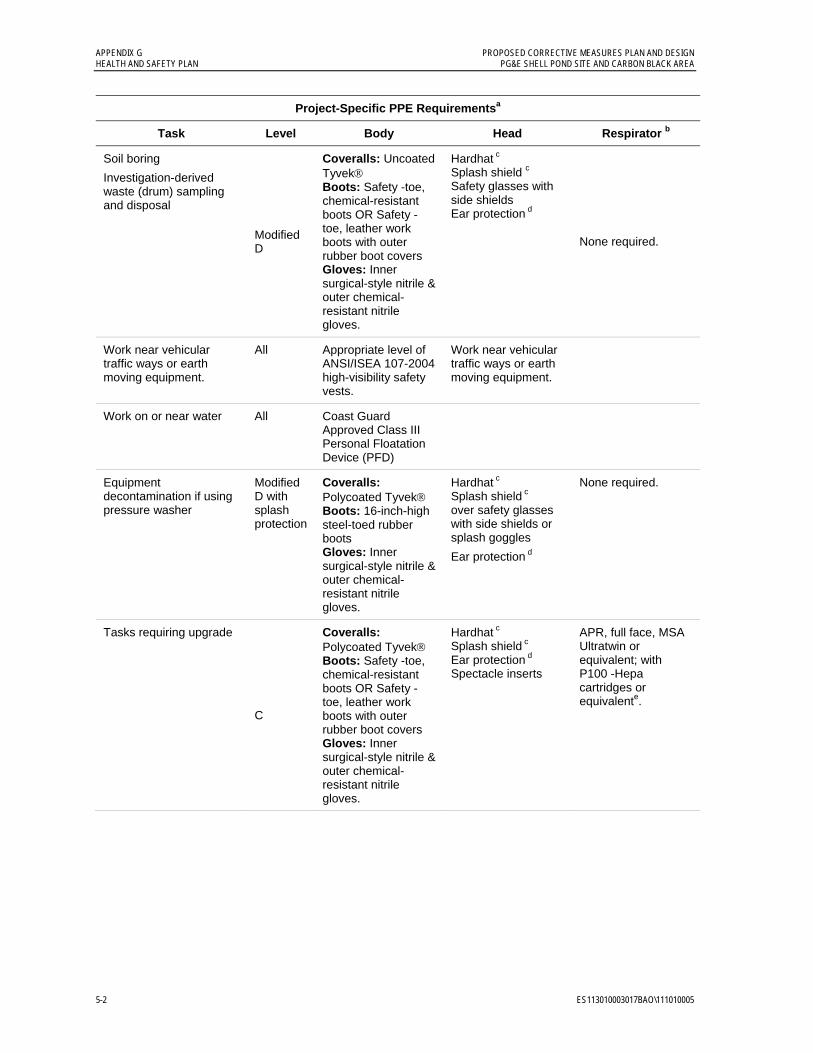
APPENDIX G PROPOSED CORRECTIVE MEASURES PLAN AND DESIGN HEALTH AND SAFETY PLAN PG&E SHELL POND SITE AND CARBON BLACK AREA
5-2 ES113010003017BAO\111010005
Project-Specific PPE Requirementsa
Task Level Body Head Respirator b
Soil boring
Investigation-derived waste (drum) sampling and disposal
Modified D
Coveralls: Uncoated Tyvek Boots: Safety -toe, chemical-resistant boots OR Safety -toe, leather work boots with outer rubber boot covers Gloves: Inner surgical-style nitrile & outer chemical-resistant nitrile gloves.
Hardhat c Splash shield c Safety glasses with side shields Ear protection d
None required.
Work near vehicular traffic ways or earth moving equipment.
All Appropriate level of ANSI/ISEA 107-2004 high-visibility safety vests.
Work near vehicular traffic ways or earth moving equipment.
Work on or near water All Coast Guard Approved Class III Personal Floatation Device (PFD)
Equipment decontamination if using pressure washer
Modified D with splash protection
Coveralls: Polycoated Tyvek Boots: 16-inch-high steel-toed rubber boots Gloves: Inner surgical-style nitrile & outer chemical-resistant nitrile gloves.
Hardhat c Splash shield c over safety glasses with side shields or splash goggles
Ear protection d
None required.
Tasks requiring upgrade
C
Coveralls: Polycoated Tyvek Boots: Safety -toe, chemical-resistant boots OR Safety -toe, leather work boots with outer rubber boot covers Gloves: Inner surgical-style nitrile & outer chemical-resistant nitrile gloves.
Hardhat c Splash shield c Ear protection d
Spectacle inserts
APR, full face, MSA Ultratwin or equivalent; with P100 -Hepa
cartridges or equivalente.

PROPOSED CORRECTIVE MEASURES PLAN AND DESIGN APPENDIX G PG&E SHELL POND SITE AND CARBON BLACK AREA HEALTH AND SAFETY PLAN
ES113010003017BAO\111010005 5-3
Project-Specific PPE Requirementsa
Task Level Body Head Respirator b
Tasks requiring upgrade
B
Coveralls: Polycoated Tyvek Boots: Safety -toe, chemical-resistant boots OR Safety -toe, leather work boots with outer rubber boot covers Gloves: Inner surgical-style nitrile & outer chemical-resistant nitrile gloves.
Hardhat c Splash shield c Ear protection d
Spectacle inserts
Positive-pressure demand self-contained breathing apparatus (SCBA); MSA Ultralite, or equivalent.
Reasons for Upgrading or Downgrading Level of Protection
Upgradef Downgrade
Request from individual performing tasks.
Change in work tasks that will increase contact or potential contact with hazardous materials.
Occurrence or likely occurrence of gas or vapor emission.
Known or suspected presence of dermal hazards.
Instrument action levels (Section 6) exceeded.
New information indicating that situation is less hazardous than originally thought.
Change in site conditions that decrease the hazard.
Change in work task that will reduce contact with hazardous materials.
a Modifications are as indicated. b No facial hair that would interfere with respirator fit is permitted. c Hardhat and splash-shield areas are to be determined by the Safety Coordinator. d Ear protection should be worn when conversations cannot be held at distances of 3 feet or less without shouting. e See cartridge change-out schedule in Section 5.2. f Performing a task that requires an upgrade to a higher level of protection (e.g., Level D to Level C) is permitted only when the PPE requirements have been approved by the safety manager
5.2 Respiratory Protection The use of respiratory protection is not anticipated for this project. However, if respiratory protection is required, implement the following controls:
Respirator users must have completed appropriate respirator training within the past 12 months. Level C training is required for air-purifying respirators (APR) use, and Level B training is required for supplied-air respirators (SAR) and self-contained breathing apparatus (SCBA) use. Specific training is required for the use of powered air-purifying respirators (PAPR).
Respirator users must complete the respirator medical monitoring protocol and be approved for the specific type of respirator to be used.
Tight-fitting facepiece respirator (negative or positive pressure) users must have passed an appropriate fit test within the past 12 months.

APPENDIX G PROPOSED CORRECTIVE MEASURES PLAN AND DESIGN HEALTH AND SAFETY PLAN PG&E SHELL POND SITE AND CARBON BLACK AREA
5-4 ES113010003017BAO\111010005
Respirator use must be limited to those activities identified in this plan. If site condition changes alter the effectiveness of the specified respiratory protection, the RHSM must be notified to amend the written plan.
Tight-fitting facepiece respirator users must be clean-shaven and must perform a user seal check before each use.
Canisters/cartridges must be replaced according to the change-out schedule specified in this plan. Respirator users must notify the SC or RHSM of any detection of vapor or gas breakthrough. The SC must report breakthrough events to the RHSM for schedule upgrade.
Respirators in regular use must be inspected before each use and during cleaning.
Respirators in regular use must be cleaned and disinfected as often as necessary to ensure they are maintained in a clean and sanitary condition.
Respirators must be properly stored to protect against contamination and deformation.
Field repair of respirators must be limited to routine maintenance. Defective respirators must be removed from service.
When breathing air is supplied by cylinder or compressor, the SC or RHSM must verify the air meets Grade D air specifications.
Respirator Cartridge Change-Out Schedule
No exposure requiring the use of respirators is anticipated. If exposure requiring the use of respiratory protection is needed, the responsible H&S professional must determine the change-out schedule for the respirator cartridges to comply with 8 CCR 5144(d)(3)C(2)(b).

ES113010003017BAO\111010005 6-1
6.0 Site Monitoring
When performing site monitoring, record all the information in a field logbook. Note date and time, describe monitoring location (for example, in breathing zone, at source and site location), and what the reading is. If action levels are reached, note it in the field logbook and note the action taken.
Exposure records (air sampling) must be preserved for the duration of employment plus 30 years. Ensure that copies of the field logbook are maintained in the project file.
Copies of all project exposure records (e.g., copies of field logbook pages where air monitoring readings are recorded and associated calibration) must be sent to the regional SPA for retention and maintained in the project files.
6.1 Direct Reading Monitoring Specifications
Instrument Tasks Action Levelsa
Action to be Taken when Action Level
reached Frequency b Calibration
Toxic Gas Monitor: MultiRAE Plus with 10.6 eV lamp (VOCs, O2, LEL, CO, H2S) (or equivalent)
All 0 - 5 ppm 5 - 50 ppm > 50 ppm
Level D Level C Level B
Initially and throughout the workday
Daily
LEL All 0-10% : 10-25% LEL: >25% LEL:
No explosion hazard Potential explosion hazard Explosion hazard; evacuate or vent
Before and during all Confined Space Entries
Daily
O2Meter: All >25%c O2:
20.9%c O2: <19.5%c O2:
Explosion hazard; evacuate or vent Normal O2 O2 deficient; vent or use SCBA
Before and during all Confined Space Entries
Daily
Hydrogen Sulfide dredging <1 ppm >1 ppm
Level D Stop work, implement engineering controls, if concentrations >1ppm persist, contact HSM to determine appropriate path forward, including an upgrade in respiratory protection.
Initially and periodically during tasks
Daily
NOTE: The GEM 2000 (or equivalent) may be used for H2S, methane LEL, and O2 using the action levels listed above.
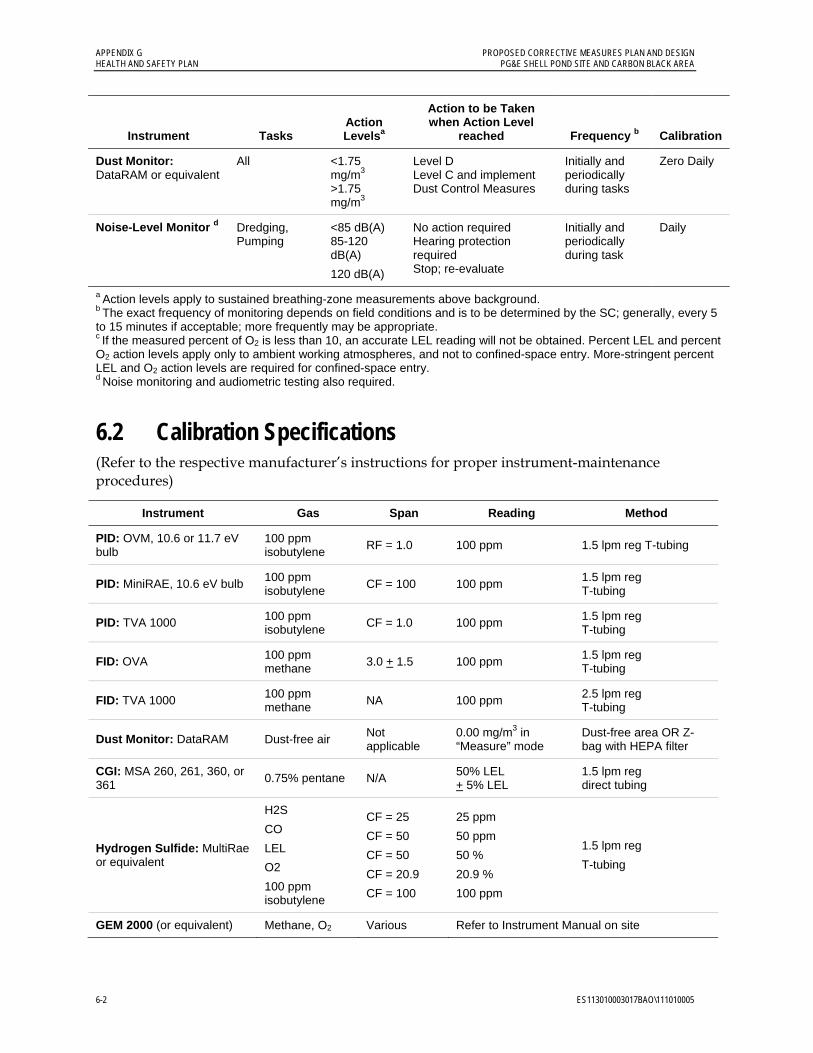
APPENDIX G PROPOSED CORRECTIVE MEASURES PLAN AND DESIGN HEALTH AND SAFETY PLAN PG&E SHELL POND SITE AND CARBON BLACK AREA
6-2 ES113010003017BAO\111010005
Instrument Tasks Action Levelsa
Action to be Taken when Action Level
reached Frequency b Calibration
Dust Monitor: DataRAM or equivalent
All <1.75 mg/m3 >1.75 mg/m3
Level D Level C and implement Dust Control Measures
Initially and periodically during tasks
Zero Daily
Noise-Level Monitor d Dredging, Pumping
<85 dB(A) 85-120 dB(A)
120 dB(A)
No action required Hearing protection required Stop; re-evaluate
Initially and periodically during task
Daily
a Action levels apply to sustained breathing-zone measurements above background. b The exact frequency of monitoring depends on field conditions and is to be determined by the SC; generally, every 5 to 15 minutes if acceptable; more frequently may be appropriate. c If the measured percent of O2 is less than 10, an accurate LEL reading will not be obtained. Percent LEL and percent O2 action levels apply only to ambient working atmospheres, and not to confined-space entry. More-stringent percent LEL and O2 action levels are required for confined-space entry. d Noise monitoring and audiometric testing also required.
6.2 Calibration Specifications (Refer to the respective manufacturer’s instructions for proper instrument-maintenance procedures)
Instrument Gas Span Reading Method
PID: OVM, 10.6 or 11.7 eV bulb
100 ppm isobutylene
RF = 1.0 100 ppm 1.5 lpm reg T-tubing
PID: MiniRAE, 10.6 eV bulb 100 ppm isobutylene
CF = 100 100 ppm 1.5 lpm reg T-tubing
PID: TVA 1000 100 ppm isobutylene
CF = 1.0 100 ppm 1.5 lpm reg T-tubing
FID: OVA 100 ppm methane
3.0 + 1.5 100 ppm 1.5 lpm reg T-tubing
FID: TVA 1000 100 ppm methane
NA 100 ppm 2.5 lpm reg T-tubing
Dust Monitor: DataRAM Dust-free air Not applicable
0.00 mg/m3 in “Measure” mode
Dust-free area OR Z-bag with HEPA filter
CGI: MSA 260, 261, 360, or 361
0.75% pentane N/A 50% LEL + 5% LEL
1.5 lpm reg direct tubing
Hydrogen Sulfide: MultiRae or equivalent
H2S
CO
LEL
O2
100 ppm isobutylene
CF = 25
CF = 50
CF = 50
CF = 20.9
CF = 100
25 ppm
50 ppm
50 %
20.9 %
100 ppm
1.5 lpm reg
T-tubing
GEM 2000 (or equivalent) Methane, O2 Various Refer to Instrument Manual on site
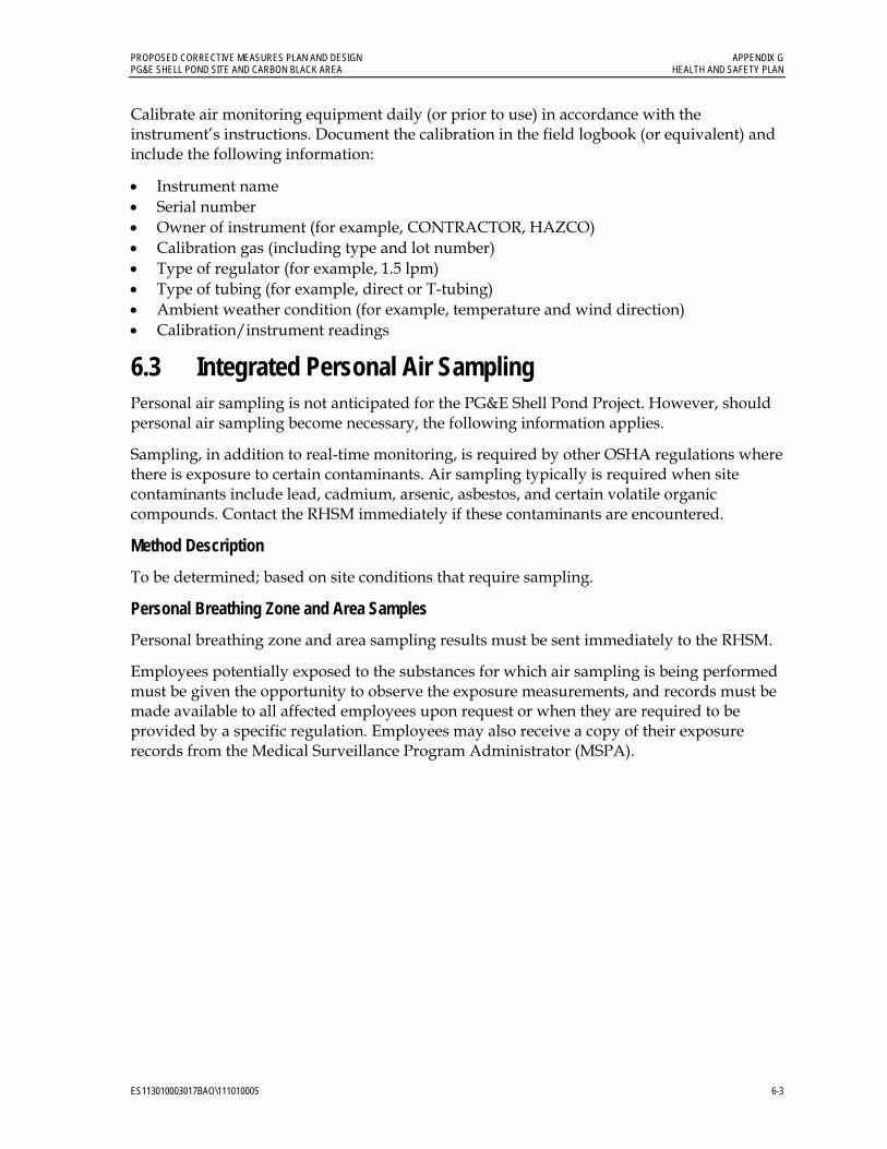
PROPOSED CORRECTIVE MEASURES PLAN AND DESIGN APPENDIX G PG&E SHELL POND SITE AND CARBON BLACK AREA HEALTH AND SAFETY PLAN
ES113010003017BAO\111010005 6-3
Calibrate air monitoring equipment daily (or prior to use) in accordance with the instrument’s instructions. Document the calibration in the field logbook (or equivalent) and include the following information:
Instrument name Serial number Owner of instrument (for example, CONTRACTOR, HAZCO) Calibration gas (including type and lot number) Type of regulator (for example, 1.5 lpm) Type of tubing (for example, direct or T-tubing) Ambient weather condition (for example, temperature and wind direction) Calibration/instrument readings
6.3 Integrated Personal Air Sampling Personal air sampling is not anticipated for the PG&E Shell Pond Project. However, should personal air sampling become necessary, the following information applies.
Sampling, in addition to real-time monitoring, is required by other OSHA regulations where there is exposure to certain contaminants. Air sampling typically is required when site contaminants include lead, cadmium, arsenic, asbestos, and certain volatile organic compounds. Contact the RHSM immediately if these contaminants are encountered.
Method Description
To be determined; based on site conditions that require sampling.
Personal Breathing Zone and Area Samples
Personal breathing zone and area sampling results must be sent immediately to the RHSM.
Employees potentially exposed to the substances for which air sampling is being performed must be given the opportunity to observe the exposure measurements, and records must be made available to all affected employees upon request or when they are required to be provided by a specific regulation. Employees may also receive a copy of their exposure records from the Medical Surveillance Program Administrator (MSPA).


ES113010003017BAO\111010005 7-1
7.0 Site Control Plan
7.1 Site Control Procedures Site control will be established to prevent the spread of contamination throughout the site and to ensure that only authorized individuals are permitted into potentially hazardous areas.
The SC will implement site control procedures including the following:
Establish support, contamination reduction, and exclusion zones. Delineate with flags or cones as appropriate. Support zone should be upwind of the site. Use access control at entry and exit from each work zone.
Establish onsite communication consisting of the following:
Line-of-sight and hand signals Air horn Two-way radio or cellular telephone if available
Establish offsite communication.
Establish and maintain the buddy system.
7.2 Remediation Work Area Zones A three-zone approach will be used to control areas where site contaminants exist. Access will be allowed only after verification of appropriate training and medical qualification. The three-zone approach will include a Support Zone (SZ), Contamination Reduction Zone (CRZ), and an Exclusion Zone (EZ). The three-zone approach is not required for construction work performed outside contaminated areas where control of site contamination is not a concern.
Specific work control zones will be established as necessary during task planning. Site work zones will be modified in the field as necessary, based on such factors as equipment used, air monitoring results, environmental conditions, or alteration of work plans. The following guidelines will be used for establishing and revising these preliminary zone designations.
7.2.1 Support Zone The SZ is an uncontaminated area (trailers, offices, field vehicles, etc.) that serves as the field support area for most operations. The SZ provides field team communications and staging for emergency response. Appropriate sanitary facilities and safety and emergency response equipment are located in this zone. Potentially contaminated personnel/materials are not allowed in this zone. The only exception will be appropriately packaged and decontaminated materials, or personnel with medical emergencies who cannot be decontaminated.

APPENDIX G PROPOSED CORRECTIVE MEASURES PLAN AND DESIGN HEALTH AND SAFETY PLAN PG&E SHELL POND SITE AND CARBON BLACK AREA
7-2 ES113010003017BAO\111010005
7.2.2 Contamination Reduction Zone The CRZ is established between the EZ and the SZ, upwind of the contaminated area where possible. The CRZ provides an area for decontamination of personnel, portable handheld equipment and tools, and heavy equipment. In addition, the CRZ serves as access for heavy equipment and emergency support services.
7.2.3 Exclusion Zone The EZ is established for activities that may involve exposure to site contaminants or hazardous materials or conditions. This zone will be demarcated to prevent unauthorized entry. More than one EZ may be established if there are different levels of protection to be employed or different hazards in the same work area. The EZ will be large enough to allow adequate space for the activity to be completed, including field personnel and equipment, as well as necessary emergency equipment.
The EZ will be demarcated with some form of physical barrier or signage. The physical barrier or signage will be placed so that they are visible to personnel approaching or working in the area. Barriers and boundary markers will be removed when no longer needed.
7.2.4 Other Controlled Areas Other work areas may need to be controlled due to the presence of an uncontrolled hazard, to warn workers of requirements, or to prevent unauthorized entry. Examples include general construction work areas, open excavations, high noise areas, vehicle access areas, and similar activities or limited access locations. These areas will be clearly demarcated with physical barriers (fencing, cones, reinforced caution tape or rope) as necessary and posted with appropriate signage.

ES113010003017BAO\111010005 8-1
8.0 Decontamination
Decontamination areas will be established for work in potentially contaminated areas to prevent the spread of contamination. Decontamination areas will be upwind of the EZ where possible and will consider adjacent or nearby projects and personnel. The SC will establish and monitor the decontamination procedures and their effectiveness. Decontamination procedures found to be ineffective will be modified by the SC. The SC will ensure that procedures are established for disposing of materials generated on the site.
No eating, drinking, or smoking is permitted in contaminated areas and in exclusion or decontamination zones. The SC should establish areas for eating, drinking, and smoking.
8.1 Contamination Prevention Refer to Section 3.5 for information on likely locations of contaminants of concern. Preventing or avoiding contamination of personnel, tools, and equipment will be considered in planning work activities at all field locations. Good contamination prevention and avoidance practices will assist in preventing worker exposure and result in a more efficient decontamination process. Procedures for contamination prevention and avoidance include the following:
Do not walk through areas of obvious or known contamination.
Do not directly handle or touch contaminated materials.
Make sure there are no cuts or tears in PPE.
Fasten all closures in suits and cover them with duct tape, if appropriate.
Take particular care to protect any skin injuries.
Stay upwind of airborne contamination, where possible.
Do not eat or drink in contaminated work areas.
Do not carry food, beverages, tobacco, or flame-producing equipment into contaminated work areas.
Minimize the number of personnel and amount of equipment in contaminated areas to that necessary for accomplishing the work.
Choose tools and equipment with nonporous exterior surfaces that can be easily cleaned and decontaminated.
Cover monitoring and sampling equipment with clear plastic, leaving openings for the sampling ports, as necessary.
Minimize the amount of tools and equipment necessary in contaminated areas.

APPENDIX G PROPOSED CORRECTIVE MEASURES PLAN AND DESIGN HEALTH AND SAFETY PLAN PG&E SHELL POND SITE AND CARBON BLACK AREA
8-2 ES113010003017BAO\111010005
8.2 Personnel and Equipment Decontamination Personnel exiting an EZ must ensure that they do not spread potential contamination into clean areas or increase their potential for ingesting or inhaling potential contaminants. Personal decontamination may range from removing outer gloves when exiting the EZ, to proceeding through an outer layer doffing station including a boot and glove wash and rinse and washing equipment. Equipment that has come into contact with contaminated media must also be cleaned/decontaminated when it leaves the EZ.
8.3 Decontamination During Medical Emergencies Standard personnel decontamination practices will be followed whenever possible. For emergency life saving first aid or medical treatment, normal decontamination procedures may need to be abbreviated or omitted. In this situation, site personnel must accompany contaminated victims to advise emergency response personnel on potential contamination present and proper decontamination procedures.
Outer garments may be removed if they do not cause delays, interfere with treatment, or aggravate the problem. Protective clothing can be cut away. If the outer garments cannot be safely removed, a plastic barrier between the individual and clean surfaces should be used to help prevent contaminating the inside of ambulances or medical personnel. Outer garments can then be removed at the medical facility.
8.4 Waste Collection and Disposal All contaminated material generated through the personnel and equipment decontamination processes (e.g., contaminated disposable items, gross debris, liquids, sludges) will be properly containerized and labeled, stored at a secure location, and disposed of in accordance with the project plans.
8.5 Diagram of Personnel-Decontamination Line Figure 1 illustrates a conceptual establishment of work zones. A site-specific map will be prepared by the selected contractor that includes locations of decontamination areas, exclusion zones, first aid stations, emergency equipment, assembly areas, site entrance and exit, evacuation routes, and telephones.

FIGURE 1 Conceptual Diagram of Remediation Work Area and Decontamination AreasPG&E Shell Pond and Carbon Black Area ProjectBay Point, California
ES032411184221BAO ConceptualDiagram_RemedDeconAreas.indd 04-11-11 lho
EMPLOYEE PARKING
FLAGGER/TRAFFIC CONTROL
ALTERNATEEMPLOYEEPARKING
ALTERNATEEQUIPMENTSTORAGE
OFFICE & LAB TRAILER AND SAFETY EQUIPMENT STORAGE

ES113010003017BAO\111010005 9-1
9.0 Site-Control Plan
9.1 Site-Control Procedures The SC will be responsible for the following:
Conduct a site safety briefing before starting field activities or as tasks and site conditions change. Briefing topics include general discussion of the HSP, site-specific hazards, locations of work zones, PPE requirements, equipment, special procedures, and emergencies.
Record attendance at safety briefings in a logbook and document the topics discussed.
Post the OSHA job-site poster in a central and conspicuous location. Establish support, decontamination, and exclusion zones. Delineate with flags or cones as appropriate. Support zone should be upwind of the site. Use access control at entry and exit from each work zone.
Establish onsite communication consisting of the following:
Line-of-sight and hand signals Air horn Two-way radio or cellular telephone if available
Establish offsite communication.
Establish and maintain the buddy system.
Conduct initial air monitoring in appropriate level of protection.
Conduct periodic inspections of work practices to determine the effectiveness of the HSP. Deficiencies are to be noted, reported, and corrected.
9.2 Hazwoper Compliance Plan Certain parts of the site work are covered by state or federal Hazwoper standards and therefore require training and medical monitoring. Anticipated Hazwoper tasks (Section 2.1.1) might occur consecutively or concurrently with respect to non-Hazwoper tasks. This section outlines procedures to be followed when approved activities specified in Section 2.1.2 do not require 24- or 40-hour training. Non-Hazwoper-trained personnel also must be trained in accordance with other state and federal OSHA requirements.
In many cases, air sampling, in addition to real-time monitoring, must confirm that there is no exposure to gases or vapors before non-Hazwoper-trained personnel are allowed on the site, or while non-Hazwoper-trained staff is working in proximity to Hazwoper activities. When non-Hazwoper-trained personnel are at risk of exposure, the SC must post the exclusion zone and inform non-Hazwoper-trained personnel of the:

APPENDIX G PROPOSED CORRECTIVE MEASURES PLAN AND DESIGN HEALTH AND SAFETY PLAN PG&E SHELL POND SITE AND CARBON BLACK AREA
9-2 ES113010003017BAO\111010005
Nature of the existing contamination and its locations Limitations of their access Emergency action plan for the site
Periodic air monitoring with direct-reading instruments conducted during regulated tasks also should be used to ensure that non-Hazwoper-trained personnel (e.g., in an adjacent area) are not exposed to airborne contaminants.
When exposure is possible, non-Hazwoper-trained personnel must be removed from the site until it can be demonstrated that there is no longer a potential for exposure to health and safety hazards.

ES113010003017BAO\111010005 10-1
10.0 Emergency Response Plan
10.1 Pre-Emergency Planning The Emergency Response Coordinator (ERC) will perform pre-emergency planning tasks before starting field activities and coordinate emergency response with onsite parties, the facility, and local emergency-service providers as appropriate. Pre-emergency tasks include the following:
Review the facility emergency and contingency plans where applicable.
Determine what onsite communication equipment is available (e.g., two-way radio, air horn).
Determine what offsite communication equipment is needed (e.g., nearest telephone, cell phone).
Confirm and post emergency telephone numbers, evacuation routes, assembly areas, and route to hospital; communicate the information to onsite personnel.
Field Trailers: Post “Exit” signs above exit doors, and post “Fire Extinguisher” signs above locations of extinguishers. Keep areas near exits and extinguishers clear.
Review changed site conditions, onsite operations, and personnel availability in relation to emergency response procedures.
Where appropriate and acceptable to the client, inform emergency room and ambulance and emergency response teams of anticipated types of site emergencies.
Designate one vehicle as the emergency vehicle; place hospital directions and map inside; keep keys in ignition during field activities.
Inventory and check site emergency equipment, supplies, and potable water.
Communicate emergency procedures for personnel injury, exposures, fires, explosions, and releases.
Rehearse the emergency response plan before site activities begin, including driving route to hospital. Drills should take place periodically but no less than once a year.
Brief new workers on the emergency response plan.
Evaluate emergency response actions and initiate appropriate follow-up actions.

APPENDIX G PROPOSED CORRECTIVE MEASURES PLAN AND DESIGN HEALTH AND SAFETY PLAN PG&E SHELL POND SITE AND CARBON BLACK AREA
10-2 ES113010003017BAO\111010005
10.2 Emergency Equipment and Supplies The ERC will mark the locations of emergency equipment on the site map and post the map. The table below lists emergency equipment and supplies and their location.
Emergency Equipment and Supplies Location
20 (or two 10) class A,B,C fire extinguishers
First aid kit
Eye wash
Emergency shower
Potable water
Bloodborne-pathogen kit
Additional equipment (specify):
10.3 Incident Response If fires, explosions, or chemical releases occur, actions to be taken include the following:
Notify appropriate response personnel. Shut down operations and evacuate the immediate work area. Account for personnel at the designated assembly area(s). Assess the need for site evacuation, and evacuate the site as warranted. Notify and submit reports to clients as required in contract.
Small fires or spills posing minimal safety or health hazards may be controlled with onsite spill kits or fire extinguishers without evacuating the site. When in doubt, evacuate. Follow the incident reporting procedures in Section 10.7.
10.4 Emergency Medical Treatment Emergency medical treatment is needed when there is a life-threatening injury (such as severe bleeding, loss of consciousness, breathing/heart has stopped). When in doubt if an injury is life-threatening, treat it as needing emergency medical treatment as follows:
Notify 911 or other appropriate emergency response authorities as listed in Emergency Contacts at the front of this HSP.
The ERC will assume charge during a medical emergency until the ambulance arrives or until the injured person is admitted to the emergency room.
To prevent further injury, perform decontamination (if applicable) where feasible; lifesaving and first aid or medical treatment takes priority.
Initiate first aid and CPR where feasible.
Ensure that the injured person is accompanied to the emergency room.

PROPOSED CORRECTIVE MEASURES PLAN AND DESIGN APPENDIX G PG&E SHELL POND SITE AND CARBON BLACK AREA HEALTH AND SAFETY PLAN
ES113010003017BAO\111010005 10-3
Notify and submit reports to client as required in contract.
10.5 Evacuation Evacuation routes, assembly areas, and severe weather shelters (and alternative routes
and assembly areas) will be specified on the site map.
Evacuation route(s) and assembly area(s) will be designated by the ERC or designee before work begins.
Personnel will assemble at the assembly area(s) upon hearing the emergency signal for evacuation.
The ERC and a “buddy” will remain onsite after the site has been evacuated (if safe) to assist local responders and advise them of the nature and location of the incident.
The ERC will account for all personnel in the onsite assembly area.
A designated person will account for personnel at alternate assembly area(s).
The ERC will follow the incident reporting procedures in Section 10.7.
10.6 Evacuation Signals The table below summarizes emergency signals and their meaning.
Signal Meaning
Grasping throat with hand Emergency; help me.
Thumbs up OK; understood.
Grasping buddy’s wrist Leave area now.
Continuous sounding of horn Emergency; leave site now.
10.7 Incident Notification and Reporting Immediately notify the PM, ERC, or RHSM about any project incident (fire,
spill/release, injury/illness, near miss, property damage, or security-related).
Report serious incidents (life-threatening injury/illness, death, kidnap/missing person, terrorism, property damage greater than $500K, significant environmental release) immediately to the ERC, PM, or RHSM. The Serious Incident Reporting number is 720-286-4911.
Incident investigations must be initiated and completed as soon as possible but no later than 72 hours after the incident.


ES113010003017BAO\111010005 11-1
11.0 Attachments
Attachment 1: Employee Signoff Form
Attachment 2: Chemical Inventory/Register Form
Attachment 3: Chemical-Specific Training Form
Attachment 4: Project Activity Self-Assessment Checklists/Permits/Forms
Attachment 5: Material Safety Data Sheets
Attachment 6: Tick Fact Sheet
Attachment 7: Notice of Safety Violation Form
Attachment 8: Stop Work Order Form


ES113010003017BAO\111010005
Attachment 1
Employee Signoff Form – Health and Safety Plan
EMPLOYEE SIGNOFF FORM Health and Safety Plan
The project employees and subcontractors listed below have been provided with a copy of this HSP, have read it and understand it, and agree to abide by its provisions.
Project Name: Project Number:
EMPLOYEE NAME (Please print) EMPLOYEE SIGNATURE COMPANY DATE


ES113010003017BAO\111010005
Attachment 2
Chemical Inventory/Register Form – Health and Safety Plan
CHEMICAL INVENTORY/REGISTER FORM
Location: _______________________________________________________________________
Hazard Communication Coordinator: _____________________________________________
Office Warehouse Laboratory Project: ________________________ Project No.: ____________________
Regulated Product Location Container
labeled (if yes)
MSDS available (if yes)
MSDS for the listed products will be maintained at: ________________________________


ES113010003017BAO\111010005
Attachment 3
Chemical-Specific Training Form – Health and Safety Plan
CHEMICAL-SPECIFIC TRAINING FORM Location: Project #:
Hazard Communication Coordinator Trainer:
TRAINING PARTICIPANTS:
NAME SIGNATURE NAME SIGNATURE
REGULATED PRODUCTS/TASKS COVERED BY THIS TRAINING: The Hazard Communication Coordinator shall use the product MSDS to provide the following information concerning each of the products listed above.
Physical and health hazards
Control measures that can be used to provide protection (including appropriate work practices, emergency procedures, and personal protective equipment to be used)
Methods and observations used to detect the presence or release of the regulated product in the workplace (including periodic monitoring, continuous monitoring devices, visual appearance or odor of regulated product when being released, etc.)
Training participants shall have the opportunity to ask questions concerning these products and, upon completion of this training, will understand the product hazards and appropriate control measures available for their protection.
Copies of MSDSs, chemical inventories, and hazard communication program shall be made available for employee review in the facility/project hazard communication file.


ES113010003017BAO\111010005
Attachment 4
Health and Safety Plan
Project Activity Self-Assessment Checklists/Permits/Forms
Earthmoving Equipment
Electrical
Excavations
Hand and Power Tools
Hazardous Materials Handling
Manual Lifting
Methylene Chloride
Personal Protective Equipment
Traffic Control


ES113010003017BAO\111010005
Attachment 5
Material Safety Data Sheets – Health and Safety Plan


ES113010003017BAO\111010005
CALL–IN CONTACT FORM
Date of site work:_______________ Expected start time:______________
Name of employee in the field:_____________________________________
Name of employee responsible to receive contact:
Client emergency contact:
Employee’s contact numbers:
Radio #__________________________
Cell phone #______________________
Address and location of work:________________________________________________
Directions/map:
Planned activity:____________________________________________________________
Specified frequency and time for call in:________________________________________
Time Verified Location
If lone worker fails to call in at specified frequency/time:
1) Call worker’s radio and cell to determine if an emergency exists.
2) If no reply, immediately call client security/emergency service if there is one at the site.
3) If there is no client security, call Emergency Services (911). Inform the dispatcher there is a lone worker who cannot be contacted and there may be an emergency onsite. Provide the lone worker’s name, his/her last known location, and your contact information.
4) After Emergency Services have been contacted, call the other emergency contacts, Project Manager, and Health and Safety Manager.


ES113010003017BAO\111010005
Attachment 6
Tick Fact Sheet – Health and Safety Plan


ES113010003017BAO\111010005
Tick-Borne Pathogens Six tick-borne pathogens present a significant field hazard, and in some areas account for more than half of our serious field incidents. These procedures should be applied during any field activity where vegetation is present.
Hazard Control
The methods for controlling exposure to ticks include, in order of most-preferred to least:
Avoiding tick habitats and ceasing operations in heavily infested areas
Reducing tick abundance through habitat disruption or application of acracide
Personal protection through use of repellants and protective clothing
Frequent tick inspections and proper hygiene
Vaccinations are not available and preventative antibiotic treatment after a bite is generally not recommended.
Avoidance and Reduction of Ticks
To the extent practical, tick habitats should be avoided. In areas with significant tick infestation, consider stopping work and withdrawing from area until adequate tick population control can be achieved. Stopping and withdrawing should be considered as seriously as entering an area without proper energy control or with elevated airborne contaminants – tickborne pathogens present risk of serious illness!
In areas where significant population density or infestation exists, tick reduction should be considered. Tick reduction can be achieved by disrupting tick habitats and/or direct population reduction through the use of tick-toxic pesticides (Damminix, Dursban, Sevin, etc.).
Habitat disruption may include only simple vegetative maintenance such as removing leaf litter and trimming grass and brush. Tick populations can be reduced between 72 and 100% when leaf litter alone is removed. In more heavily infested areas, habitat disruption may include grubbing, tree trimming or removal, and pesticide application (Damminix, Dursban, Sevin, etc.). This approach is practical in smaller, localized areas or perimeter areas that require occasional access. Habitat controls are to be implemented with appropriate health and safety controls, in compliance with applicable environmental requirements, and may be best left to the property owner or tenant, or licensed pesticide vendor. Caution should be exercised when using chemical repellents or pesticides in or around areas where environmental or industrial media samples will be collected for analysis.
Personal Protection
After other prevention and controls are implemented, personal protection is still necessary in controlling exposure to ticks. Personal protection must include all of the following steps:
So that ticks may be seen on your clothing, wear light-colored clothing. Full-body New Tyvek (paper-like disposable coveralls) may also be used.

ES113010003017BAO\111010005
To prevent ticks from getting underneath clothing, tuck pant legs into socks or tape to boots.
Wear long-sleeved shirts, a hat, and high boots.
Apply DEET repellent to exposed skin or clothing per product label.
Apply permethrin repellent to the outside of boots and clothing before wearing, per product label.
Frequently check for ticks and remove from clothing.
Where site conditions warrant (vegetation above knee height, tick endemic area) or when tasks warrant (e.g., having to sit/kneel in vegetation) that diminish the effectiveness of the other controls mentioned above, bug-out suits (obtained from MKE warehouse)/Tyvek shall be used. Bug-out suits are more breathable than Tyvek.
At the end of the day search your entire body for ticks (particularly groin, armpits, neck and head) and shower.
To prevent pathogen transmission through mucous membranes or broken/cut skin, wash or disinfect hands and/or wear surgical-style nitrile gloves anytime ticks are handled.
Pregnant individuals and individuals using prescription medications should consult with their physician and/or pharmacists before using chemical repellents. Because human health effects may not be fully known, use of chemical repellents should be kept to a minimum frequency and quantity. Always follow manufacturers’ use instructions and precautions. Wash hands after handling, applying, or removing protective gear and clothing. Avoid hand-to-face contact, eating, drinking, smoking, etc. when applying or using repellents. Remove and wash clothes per repellent product label. Chemical repellents should not be used on infants and children.
Vaccinations are generally not available for tick-borne pathogens. Although production of the LYMErix™ lyme disease vaccination has been ceased, vaccination may still be considered under specific circumstances and with concurrence from the consulting physician. Preventative antibiotic treatment in non-ill individuals who have had a recent tick bite is recommended in specific cases only.
Tick Check
A tick check should be performed after field survey before entering the field vehicle (you do not want to infest your field vehicle with ticks). Have your field partner check your back; the backs of your legs, arms, and neck; and your hairline. Shake off clothing as thorough as possible before entering the vehicle. Once the field day is complete, repeat this procedure and perform a thorough self check.
If a tick has embedded itself into the skin, remove the tick as described below. After removal, preserve the specimen in a small air tight bag and send it to Clongen Laboratories, LLC located in Germantown, Maryland for analysis. The laboratory will have results within 1-3 days. A tick testing submission form (attached) should be properly completed and submitted with the tick.

ES113010003017BAO\111010005
Tick Removal
Use fine-tipped tweezers or shield your fingers with a tissue, paper towel, or nitrile gloves.
Grasp the tick as close to the skin surface as possible and pull upward with steady, even pressure. Do not twist or jerk the tick; this may cause the mouthparts to break off and remain in the skin. (If this happens, remove mouthparts with tweezers. Consult your healthcare provider if infection occurs.)
Do not squeeze, crush, or puncture the body of the tick because its fluids (saliva, hemolymph, gut contents) may contain infectious organisms. Releasing these organisms to the outside of the tick’s body or into the bite area may increase the chance of infectious organism transmission.
Do not handle the tick with bare hands because infectious agents may enter through mucous membranes or breaks in the skin. This precaution is particularly directed to individuals who remove ticks from domestic animals with unprotected fingers. Children, elderly persons, and immunocompromised persons may be at greater risk of infection and should avoid this procedure.
After removing the tick, thoroughly disinfect the bite site and wash your hands with soap and water.
You may wish to save the tick for identification in case you become ill. Your doctor can use the information to assist in making an accurate diagnosis. Place the tick in a plastic bag and put it in your freezer. Write the date of the bite on a piece of paper with a pencil and place it in the bag.
Note: Folklore remedies such as petroleum jelly or hot matches do little to encourage a tick to detach from skin. In fact, they may make matters worse by irritating the tick and stimulating it to release additional saliva, increasing the chances of transmitting the pathogen. These methods of tick removal should be avoided. In addition, a number of tick removal devices have been marketed, but none are better than a plain set of fine tipped tweezers.
First-Aid and Medical Treatment
Tick bites should always be treated with first-aid. Clean and wash hands and disinfect the bite site after removing embedded tick. Consult a healthcare professional if infection or symptoms and effects of tick-borne illnesses are develop.

ES113010003017BAO\111010005
Medical treatment for tick-borne infections include antibiotics and other medical interventions. Diagnosis of specific illness involves both clinical and laboratory confirmations. Preventative antibiotic treatment in non-ill individuals who have had a recent tick bite is recommended in specific cases only.
Previously infected individuals are not conferred immunity – re-infection from future tick bites can occur even after a person has contracted a tick-borne disease.
Hazard Recognition
An important step in controlling tick related hazards is understanding how to identify ticks, their habitats, their geographical locations, and signs & symptoms of tick-borne illnesses.
Tick Identification
Five varieties of hard-bodied ticks have been associated with tick-borne pathogens. These tick varieties include:
Deer (Black Legged) Tick (eastern and pacific varieties) Lone Star Tick Dog Tick Rocky Mountain Wood Tick.
Tick Habitat
On the Pacific Coast, the bacteria are transmitted to humans by the western black-legged (deer) tick. Here, ticks have been found in habitats with forest, north coastal scrub, high brush, and open grasslands. Coastal tick populations thrive in areas of high rainfall, but ticks are also found at inland locations.

ES113010003017BAO\111010005
From Left: adult female, adult male, nymph, and larvae Deer Tick (cm scale) Distribution of Pacific Deer Tick (dark green)
Dog Tick
Rocky Mountain Wood Tick
Lone Star Tick Distribution of Lone Star Tick (dark green)

ES113010003017BAO\111010005
Illnesses and Signs & Symptoms
Six notifiable tick-borne pathogens cause human illness in the United States. These pathogens may be transmitted during a tick bite—normally hours after attachment. The illnesses, presented in approximate order of most common to least, include:
Lyme (bacteria) RMSF (bacteria) Ehrlichiosis (bacteria) STARI (Southern Tick-Associated Rash Illness) (bacteria) Tularemia (Rabbit Fever) (bacteria) Babesia (protozoan parasite)
Symptoms will vary based on the illness, and may develop in infected individuals typically between 3 and 30 days after transmission. Some infected individuals will not become ill or may develop only mild symptoms. These illnesses present with some or all of the following signs & symptoms: fever, headache, muscle aches, stiff neck, joint aches, nausea, vomiting, abdominal pain, diarrhea, malaise, weakness, small solid, ring-like, or spotted rashes. The bite site may be red, swollen, or develop ulceration or lesions. A variety of long-term symptoms may result when untreated, including debilitating effects and death.

ES113010003017BAO\111010005
Attachment 7
Notice of Safety Violation Form – Health and Safety Plan


ES113010003017BAO\111010005
Attachment 8
Stop Work Order Form – Health and Safety Plan
Stop Work Order REPORT PREPARED BY:
Name: Title: Signature: Date:
ISSUE OF NONPERFORMANCE:
Description: Date of Nonperformance: ________________
CONTRACTOR SIGNATURE OF NOTIFICATION:
Name: Title: Signature: Date:
CONTRACTOR’S CORRECTIVE ACTION
Description: Date of Nonperformance: ________________
SUBCONTRACTOR SIGNATURE OF CORRECTION
Name: Title: Signature: Date: