Embed Size (px)
Citation preview

U.S. Army Corps of Engineers
Galveston District Southwestern
Division
Freeport Harbor Channel Improvement Project – General Reevaluation Report
Brazoria County, Texas
Engineering Appendix
February, 2018

This page was intentionally left blank.

i
2/2018 HDR 10024557 REV13
TABLE OF CONTENTS
1 GENERAL INFORMATION .......................................................................................................... 1
1.1 PROJECT LOCATION AND DESCRIPTION ........................................................................ 1
2 CIVIL ENGINEERING ................................................................................................................... 5
2.1 EXISTING FREEPORT HARBOR CHANNEL ...................................................................... 5 2.2 PROJECT DESIGN AND DEVELOPMENT .......................................................................... 6
2.2.1 INITIAL PLAN FORMULATION ............................................................................ 7 2.2.2 PLAN FORMULATION ............................................................................................ 8 2.2.3 RELOCATIONS ......................................................................................................... 8
2.3 DETAIL FORMULATION DESIGN PHASE ......................................................................... 9 2.3.1 REAL ESTATE .......................................................................................................... 9 2.3.2 AIDS TO NAVIGATION ........................................................................................ 17 2.3.3 ACCESS ROADS ..................................................................................................... 17
2.4 DREDGING TERMS .............................................................................................................. 17 2.4.1 ADVANCE MAINTENANCE ................................................................................. 17 2.4.2 ALLOWABLE OVERDEPTH ................................................................................. 18 2.4.3 PREDICTED SHOALING RATES ......................................................................... 18 2.4.4 DREDGING FREQUENCY ASSUMPTIONS ........................................................ 18
3 SURVEYING, MAPPING, AND OTHER GEOSPATIAL DATA REQUIREMENTS .......... 19
3.1 SURVEYS ............................................................................................................................... 19 3.2 VERTICAL DATUM .............................................................................................................. 19 3.3 HORIZONTAL DATUM ........................................................................................................ 19 3.4 TIDAL DATUM ..................................................................................................................... 19 3.5 TIDAL DATUM CONVERSION ........................................................................................... 20
4 GEOTECHNICAL ......................................................................................................................... 21
4.1 PURPOSE ............................................................................................................................... 21 4.2 PROJECT CONDITIONS ....................................................................................................... 21
4.2.1 GENERAL GEOLOGY ........................................................................................... 21 4.2.2 SOILS INVESTIGATION ....................................................................................... 21 4.2.3 SAMPLING AND TESTING ................................................................................... 22 4.2.4 SLOPE STABILITY ANALYSES ........................................................................... 23
4.3 ENGINEERING PROPOSAL ................................................................................................ 24 4.4 CONSTRUCTION SEQUENCES .......................................................................................... 25 4.5 CONSTRUCTION CONCERNS ............................................................................................ 25 4.6 DREDGED MATERIAL MANAGEMENT PLAN ............................................................... 25
4.6.1 PLACEMENT AREAS ............................................................................................ 26 4.6.2 DREDGED MATERIAL FACTORS ....................................................................... 28

ii
2/2018 HDR 10024557 REV13
4.6.3 DREDGED MATERIAL CLASSIFICATION ........................................................ 30 4.6.4 DREDGED MATERIAL QUANTITIES ................................................................. 30 4.6.5 PLACEMENT PLANS ............................................................................................. 31 4.6.6 BENEFICIAL USE OPPORTUNITIES ................................................................... 32
5 ENVIRONMENTAL ENGINEERING ........................................................................................ 37
5.1 ENVIRONMENTALLY RENEWABLE MATERIALS ........................................................ 37 5.2 DESIGN OF POSITIVE ENVIRONMENTAL ATTRIBUTES INTO THE PROJECT ....... 37 5.3 INCLUSION OF ENVIRONMENTALLY BENEFICIAL OPERATIONS AND
MANAGEMENT FOR THE PROJECT ................................................................................. 37 5.4 BENEFICIAL USES OF SPOIL OR OTHER PROJECT REFUSE DURING
CONSTRUCTION AND OPERATION ................................................................................. 37 5.5 ENERGY SAVINGS FEATURES OF THE DESIGN ........................................................... 37 5.6 MAINTENANCE OF THE ECOLOGICAL CONTINUITY IN THE PROJECT WITH THE
SURROUNDING AREA AND WITHIN THE REGION ...................................................... 37 5.7 CONSIDERATION OF INDIRECT ENVIRONMENTAL COSTS AND BENEFITS ......... 37 5.8 INTEGRATION OF ENVIRONMENTAL SENSITIVITY INTO ALL ASPECTS OF THE
PROJECT ................................................................................................................................ 38 5.9 THE PERUSAL OF THE ENVIRONMENTAL REVIEW GUIDE FOR OPERATIONS
(ERGO) WITH RESPECT TO ENVIRONMENTAL PROBLEMS THAT HAVE BECOME EVIDENT AT SIMILAR EXISTING PROJECTS AND, THROUGH FORESIGHT DURING THIS DESIGN STAGE, HAVE BEEN ADDRESSED IN THE PROJECT DESIGN .................................................................................................................................. 38
5.10 INCORPORATION OF ENVIRONMENTAL COMPLIANCE MEASURES INTO THE PROJECT DESIGN ................................................................................................................ 38
6 HYDROLOGY AND HYDRAULICS .......................................................................................... 39
6.1 PURPOSE ............................................................................................................................... 39 6.2 SEDIMENTATION ANALYSIS ............................................................................................ 39 6.3 SEA LEVEL RISE ANALYSIS ............................................................................................. 40 6.4 WAVE ANALYSIS ................................................................................................................ 40 6.5 OVERTOPPING ANALYSIS ................................................................................................ 40 6.6 HYDRODYNAMIC ANALYSIS ........................................................................................... 41 6.7 RISK BASED SURGE AND WAVE MODELING ............................................................... 41
7 STRUCTURAL REQUIREMENTS ............................................................................................. 42
8 OPERATION AND MAINTENANCE ......................................................................................... 43
9 COST ESTIMATES ....................................................................................................................... 44
9.1 REFERNCES .......................................................................................................................... 44 9.2 CLASSIFICATION AND SCOPE.......................................................................................... 44
10 REFERENCES ................................................................................................................................ 46

iii
2/2018 HDR 10024557 REV13
ATTACHMENTS
ATTACHMENT 1 DRAWINGS
ATTACHMENT 2 HYDROLOGY AND HYDRAULICS REPORT
ATTACHMENT 3 SHIP SIMULATION REPORT
ATTACHMENT 4 VALUE ENGINEERING REPORT
ATTACHMENT 5 CONSTRUCTION SCHEDULE
ATTACHMENT 6 REAL ESTATE EXHIBITS
ATTACHMENT 7 GEOTECHNICAL DATA
ATTACHMENT 8 COMPARISON AND REVIEW FOR BENEFICIAL USE
ATTACHMENT 9 ERDC RISK BASED SURGE AND WAVE MODELING REPORT
ATTACHMENT 10 TOTAL PROJECT COST SUMMARY

1
2/2018 HDR 10024557 REV13
1 GENERAL INFORMATION
This Engineering Appendix was prepared as part of the Freeport Harbor Channel Improvement Project (FHCIP) General Reevaluation Report (GRR) study under a Cost Sharing Agreement with the non-Federal sponsor, Port Freeport. The GRR study area is shown in Figure 1. Congress authorized channel improvements for Freeport Harbor in Water Resources Reform and Development Act of 2014 (WRRDA 2014). Potential modifications to the authorized project have been identified. This Engineering Appendix documents the following:
Evaluation to optimize the maximum width of the channel through the “waist” at the Dow Thumb, to the extent that such a widening can be accomplished without impacting the Hurricane Flood Protection Project (HFPP).
Evaluation of a lower bend easing to allow vessels to safely align their passage through the “waist” area with tug assistance (including addressing impacts to an existing wave barrier).
A new Turning Notch at the Upper Turning Basin will be included for analysis to enable the design vessel to facilitate safe three-point maneuvering in this reach (see Figure 2).
This Engineering Appendix follows the requirements of the Project Management Plan, dated (November 2015); guidance in ER 1110-2-1150, Appendix C; and input from Port Freeport.
Engineering studies for this deep draft navigation project included Civil Engineering, Cost Engineering, Hydrology and Hydraulics study, Geotechnical and Structural Engineering, a Ship Simulation/Navigation Study (Attachment 3), and other investigations completed by the Corps of Engineers’ Engineer Research & Development Center (ERDC) and/or as work-in-kind by the non-Federal sponsor; preliminary geotechnical investigations, in-house channel surveys; and in-house land surveys. Other engineering and design considerations included surveying and mapping, civil design, geotechnical design, operations and maintenance, cost estimates, and scheduling for construction. Preliminary alternative designs and screening-level cost estimates were developed in sufficient detail to substantiate the recommended plan and baseline cost estimate.
1.1 PROJECT LOCATION AND DESCRIPTION
Freeport Harbor is located in Brazoria County, south of the city of Freeport, along the central Texas Gulf Coast. The existing Freeport Channel has an overall length of 8.6 miles from the Stauffer Turning Basin to the Gulf of Mexico, as shown in Figure 1. This length includes a 5.2 mile stretch from the open water in the Gulf of Mexico through the jettied entrance to the Brazosport Turning Basin, a 1.3 mile stretch from the Brazosport Turning Basin to the Upper Turning Basin, and a 1.4 mile stretch from the Upper Turning Basin through the Stauffer Chemical Company Channel (“Stauffer Channel”) to the turning basin, as well as a 0.6 mile section that includes the Brazos Harbor side channel and turning basin. Stauffer Channel, originally dredged by local interests, was incorporated into the Federal project by the River and Harbor Act

2
2/2018 HDR 10024557 REV13
of 1935. This act also provided for deepening of that channel to 29 feet MLLW. Note that Stauffer Channel was later deauthorized and current depth is 19 feet MLLW.
Figure 1 GRR Study Area.
As shown in Figure 2, the proposed Recommended Plan consists of channel widening and related dredging between approximately Sta. 142+00 to Sta. 186+00 in the vicinity of the Dow Thumb. The plan includes a 46-foot MLLW depth dredging plan and widening the channel constriction to 400 feet; a new Bend Easing at the existing wave barrier between Sta. 147+00 and 160+00; a new Turning Notch at the Upper Turning Basin (Sta. 175+00 to 182+00) adjacent to Brazos Port Harbor. A proposed 3,110 linear foot HFPP levee reinforcement in locations where the channel widening impacts the stability of the existing levee will be implemented by the local sponsor (Port Freeport) according to 33 USC 408 (Section 408).

3
2/2018 HDR 10024557 REV13
Fig
ure
2 R
ecco
men
ded
Pla
n.

4
2/2018 HDR 10024557 REV13
These improvements will allow larger container ships to navigate through the Dow Thumb portion of the channel even with a vessel moored at Berth 2 (Phillips Terminal) where the bottom width of the existing Federal channel is restricted to approximately 286 feet (see Figure 3). Four economic reaches have been identified within WRRDA 2014 and are shown in Figure 3. Note that the local sponsor (Port Freeport) has received a waiver to construct a portion of Economic Reach #3 by deepening it from existing -19 feet MLLW to -46 feet MLLW as authorized in WRRDA 2014.
Figure 3 Minimum Channel Width at Dow Thumb (Existing Condition).

5
2/2018 HDR 10024557 REV13
2 CIVIL ENGINEERING
2.1 EXISTING FREEPORT HARBOR CHANNEL
The existing Freeport Channel is currently constructed to a depth of 46 feet MLLW, and dredged to a depth of 51 feet MLLW which includes 2 feet of advance maintenance and appropriate allowable overdepth, in Economic Reach #2. Deepening to 51 feet will be enacted under the 2014 WRRDA provisions. Note that the current channel is at a depth of 19 feet MLLW in Economic Reach #3 (formerly referred to as the deauthorized Lower Stauffer Channel reach). The entire Freeport Harbor Channel is shown in Figure 4.
Figure 4 Freeport Harbor Channel Reaches.
The existing channel widths vary and are to be modified based on the recommendation of local pilots, a detailed ship simulations (see Attachment 3) and other factors. Table 1 shows the authorized dimensions of the Freeport Harbor. The channel width is currently variable, with a minimum width of 286 feet near Sta. 166+00 in Economic Reach #2, adjacent to the Dow Thumb. According to pilots, the channel around the Dow Thumb must be widened to accommodate the design vessels (Panamax vessels) and enable them safe navigation to and from Berth Seven (7) at the Velasco Container Terminal. Due to the small cross sectional area and tight bend of the channel near the Dow Thumb, large vessels must pass at a slow speed to prevent potential damage to moored vessels caused by pressure field effects generated by the passing vessel. The

6
2/2018 HDR 10024557 REV13
slow speed is not sufficient for steerageway and safe control of the vessel. To facilitate safe maneuvering, a Bend Easing at the wave barrier (Sta.147+00 to Sta. 160+00) as well as a Turning Notch at the Upper Turning Basin (Sta. 182+00 to Sta. 175+00) were incorporated, allowing the design vessels to align with the channel before they navigate past the Dow Thumb. The proposed plan will be enhanced with a new Bend Easing at the wave barrier between Sta. 147+00 and 160+00 to allow the vessel to properly align itself prior to passing through the waist. Tug assist will be required for all large vessels moving through the Dow Thumb to overcome some of the steerage issues.
Table 1 Authorized Dimensions for Freeport Harbor.
Channel Segment Stations Depth in feet
MLLW (MLT)
Width (feet)
Length (miles)
From To
Outer Bar Channel
Outer Bar Channel -300+00 0+00 48 (47) 400* 5.68
Jetty Channel 0+000 71+52 46 (45) 400* 1.35
Lower Turning Basin 71+52 78+52 46 (45) 750 0.13
Main Channel
Channel to Brazosport Turning Basin 78+52 106+74 46 (45) 400 0.53
Brazosport Turning Basin 106+74 115+52 46 (45) 1000 0.17
Channel to Upper Turning Basin 115+52 174+54 46 (45) 350-375 1.12
Upper Turning Basin 174+54 184+20 46 (45) 1200 0.18
Brazos Harbor
Channel to Brazos Harbor 8+00 28+00 37 (36) 200 0.38
Brazos Harbor Turning Basin 0+00 8+00 37 (36) 750 0.15
Stauffer Channel (Deauthorized)
Stauffer Channel, Lower Reach 184+20 222+00 31 (30) 200 0.72
Stauffer Channel, Upper Reach 222+00 260+00 31 (30) 500 0.72
* Note that the Outer Bar Channel and Jetty Channel were widened from 400 ft to 600 ft in 2015 by the local sponsor. The widened channel is maintained by USACE as part of a Federal Assumption of Maintenance agreement.
2.2 PROJECT DESIGN AND DEVELOPMENT
During the GRR study, different alternative navigation channel plans were evaluated. The GRR study consisted of a three-phase process: Initial Plan Formulation, Plan Formulation, and Detail Design. Note the Final Design required for bid documents will occur during Preconstruction Engineering and Design (PED) and no further reference will be made beyond what is needed to communicate the GRR design.

7
2/2018 HDR 10024557 REV13
Alternatives developed by the PDT include the following:
No Action Alternative: proposes no modification to the channel’s depth and width.
Alternative 1: proposes channel widening at Dow Thumb to 375 feet, a Bend Easing and a Turning Notch.
Alternative 2: proposes channel widening at Dow Thumb to 400 feet, a Bend Easing and a Turning Notch
Alternative 3: proposes channel widening at Dow Thumb to 425 feet, a Bend Easing and a Turning Notch
Results of the GRR investigation indicate that Alternative 2 provides for safe passage of the design vessel to and from Berth 7 and is selected as the preferred option. The following sections provide more detail on the three-phase process.
2.2.1 INITIAL PLAN FORMULATION
The GRR is intended to evaluate the previously authorized project and recommend modifications to that plan based on changed economic and physical conditions. The scope of the initial plan formulation is to evaluate the identified modifications related to channel widths and bend-easing that allow for the projected fleet of Panamax vessels and to define the “First Increment" modifications to the recommended plan as authorized by WRRDA 2014.
The initial alternatives considered various widths, all with project depths of 46 feet MLLW to match the depth of the existing channel. Initial Plan Formulation involved screening initial alternatives and eliminating alternatives that rated low based on economics, safety and operations. Alternatives that did not significantly improve navigation or have support from the non-Federal sponsor, or in the PDT’s judgment were cost prohibitive, were not considered.
The initial plan formulation will be referred to as the “First Increment,” and includes the following:
• Evaluate the authorized channel improvements in the Lower Stauffer Channel at a depth of 46 feet MLLW.
• Evaluate an optimized/maximized width of the channel through the “waist” at the Dow Thumb, to the extent that such widening can be accomplished with minimal impact to the HFPP.
• Evaluate a "lower Bend Easing" to allow Panamax vessel to align for passage through the waist area with tug assistance (including addressing the wave barrier impacts).
• Evaluate a turning notch to allow a three-point turn when leaving the container berth.
8
2/2018 HDR 10024557 REV13
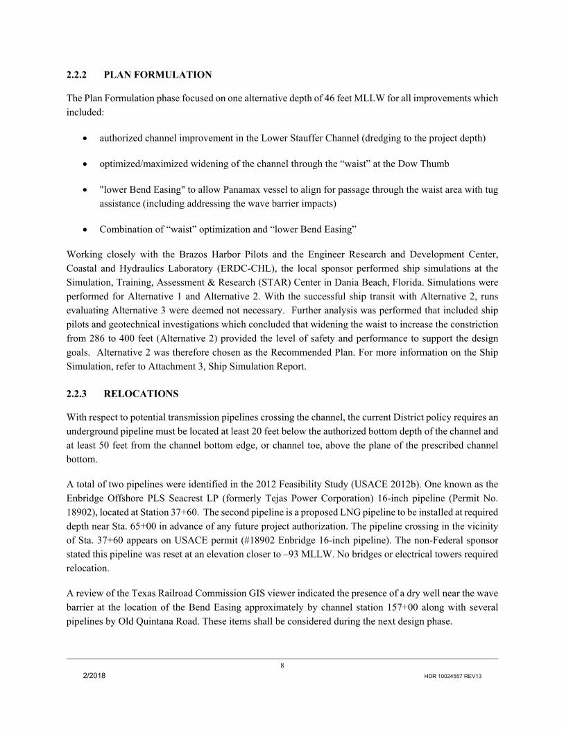
2.2.2 PLAN FORMULATION
The Plan Formulation phase focused on one alternative depth of 46 feet MLLW for all improvements which included:
authorized channel improvement in the Lower Stauffer Channel (dredging to the project depth)
optimized/maximized widening of the channel through the “waist” at the Dow Thumb
"lower Bend Easing" to allow Panamax vessel to align for passage through the waist area with tug assistance (including addressing the wave barrier impacts)
Combination of “waist” optimization and “lower Bend Easing”
Working closely with the Brazos Harbor Pilots and the Engineer Research and Development Center, Coastal and Hydraulics Laboratory (ERDC-CHL), the local sponsor performed ship simulations at the Simulation, Training, Assessment & Research (STAR) Center in Dania Beach, Florida. Simulations were performed for Alternative 1 and Alternative 2. With the successful ship transit with Alternative 2, runs evaluating Alternative 3 were deemed not necessary. Further analysis was performed that included ship pilots and geotechnical investigations which concluded that widening the waist to increase the constriction from 286 to 400 feet (Alternative 2) provided the level of safety and performance to support the design goals. Alternative 2 was therefore chosen as the Recommended Plan. For more information on the Ship Simulation, refer to Attachment 3, Ship Simulation Report.
2.2.3 RELOCATIONS
With respect to potential transmission pipelines crossing the channel, the current District policy requires an underground pipeline must be located at least 20 feet below the authorized bottom depth of the channel and at least 50 feet from the channel bottom edge, or channel toe, above the plane of the prescribed channel bottom.
A total of two pipelines were identified in the 2012 Feasibility Study (USACE 2012b). One known as the Enbridge Offshore PLS Seacrest LP (formerly Tejas Power Corporation) 16-inch pipeline (Permit No. 18902), located at Station 37+60. The second pipeline is a proposed LNG pipeline to be installed at required depth near Sta. 65+00 in advance of any future project authorization. The pipeline crossing in the vicinity of Sta. 37+60 appears on USACE permit (#18902 Enbridge 16-inch pipeline). The non-Federal sponsor stated this pipeline was reset at an elevation closer to –93 MLLW. No bridges or electrical towers required relocation.
A review of the Texas Railroad Commission GIS viewer indicated the presence of a dry well near the wave barrier at the location of the Bend Easing approximately by channel station 157+00 along with several pipelines by Old Quintana Road. These items shall be considered during the next design phase.

9
2/2018 HDR 10024557 REV13
2.3 DETAIL FORMULATION DESIGN PHASE
2.3.1 REAL ESTATE
2.3.1.1 GENERAL BACKGROUND
This Real Estate Plan (REP) is the real estate work product of the U.S. Army Corps of Engineers, Galveston District, Real Estate Division (the “District”) that supports project plan formulation for the FHCIP. It identifies and describes the lands, easements, and rights-of-way (LER) required for the construction, operation and maintenance of the proposed project, including those required for relocations, borrow material, and dredged or excavated material disposal. Further, the REP describes the estimated LERRD value, together with the estimated administrative and incidental costs attributable to providing project LERRD, and the acquisition process.
2.3.1.2 PROJECT TYPE AND AVAILABILITY
The Galveston District of the Corps is currently conducting a feasibility study of the navigation improvements at the Harbor that are addressing both increased channel width and depth under the authority of River and Harbor Act of 1970 and Section 216 of the Flood Control Act of 1970, which authorizes investigations for modification of completed projects or their operation when found advisable due to significantly changed physical or economic conditions and for improving the quality of the environment in the overall public interest. Because of the local interest in expediting improvements for the harbor, Port Freeport, is proposing to implement a deepening and selective widening project at its expense with the request that the Federal Government accept responsibility for future Operation and Maintenance (O&M) of the deepening and selective widening project. Authority for the non-Federal interests to conduct the feasibility study is provided in Section 203 of WRDA 1986 (PL99-662). The non-federal interests are constructing the deepening and selective widening project under the Authority of Section 204(a) of WRDA 1986, as amended. The non-federal interests are asking the Federal Government to assume O&M of the completed project under Section 204(f) of WRDA 1986. Table 2 sets forth the multiple authorizations applicable to the Project, including dates and descriptions of authorized Project features. These authorizations provide the historical foundation for this REP in support of this GRR.

10
2/2018 HDR 10024557 REV13
Table 2 Applicable Project Authorizations. Date
Authorizing Act
Project and Work Authorized for Freeport Harbor, Texas
Documents
June 14, 1880 Provided for construction of jetties for controlling and improving the channel over the bar at mouth of Brazos River
Rivers and Harbors act of 1880
March 3, 1899 Dredging and other work necessary in judgment of Secretary of War for improving harbor; for taking over jetties and privately built works at mouth of river
River and Harbor Act of 1899, 55th Congress, Ch. 425
March 2, 1907 Examination authorized. Work later confined to maintenance of jetties
H. Doc. 1087, 60th Cong., 2nd Sess.
Feb 27, 1911 Repairs to jetties and dredging River and Harbor Act of 1911, P.L. 61‐425
March 4, 1913 Construct seagoing hopper dredge River and Harbor Act of 1913, P.L. 62‐429
August 8, 1917 Purchase of one 15-inch pipeline dredge and equipment, its operation of 3 years, operation of seagoing dredge one-half time for 3 years, and repairs to jetties
River and Harbor Act of 1917, P.L. 65‐37
March 3, 20181 Diversion dam, diversion channel, and necessary auxiliary works Rivers and Harbors Committee Doc. 10, 68th Cong., 2nd Sess.
July 3, 1930 Maintenance of diversion channel at expense of local interest Rivers and Harbors Committee Doc. 18, 70th Cong., 1st Sess.
August 30, 1935 Maintenance of present project dimensions of channels and basins at Federal expense
Rivers and Harbors Committee Docs. 15, 72nd Cong., 1st Sess., and 29, 73rd Cong., 2nd Sess.
July 3, 1958 Relocate outer bar channel on straight alignment with jetty channel and maintain Brazos Harbor entrance channel and turning basin (constructed by local interests)
Rivers & Harbor Act of 1958 (House Doc. 433, 84th Cong., 2nd Sess.)
October 5, 1961 Modification of HD 1469 revoking certain provisions of local cooperation
PL 394, 87th Cong.
Dec 31, 1970
Relocation of entrance channel and deepen to 47 feet; enlargement to a depth of 45 feet and relocation of jetty channel and inside main channel; deepening to 45 feet of channel to Brazosport; enlargement of the widened area of Quintana Point to provide a depth of 45 feet with a 750‐foot diameter turning area; Brazosport turning basin to 45 feet deep with a 1,000-foot turning area; a new turning basin with a 1,200-foot diameter turning area and 45 feet deep; deepening Brazosport channel to 36 by 750 feet diameter; flared approaches from Brazos Harbor Channel; relocation of north jetty and rehabilitation of south jetty
R&H Act of 1970, PL 91‐611; 84 Stat.1818.2
Nov 17, 1986 Modified local cooperation requirements for the 1970 Act Sec. 101, PL 99‐662
Nov 8, 2007 Amends Sec 101 of Rivers and Harbor Act of 1970 to make all costs for removal of the sunken vessel COMSTOCK a Federal responsibility
Sec. 3148, PL 110‐114
June 10, 2014
Deepen the Outer Bar Channel from the jetties into the Gulf of Mexico to –58 feet MLLW; Deepen from the end of the jetties in the Gulf of Mexico to the Lower Turning Basin to–56 feet MLLW; Deepen the Main Channel from the Lower Turning Basin to Sta. 132+66 to–56 feet MLLW; Deepen from Sta. 132+66 through the Upper Turning Basin to–51 feet MLLW; Deepen and widen the lower 3,700 feet of the Stauffer Channel to a depth of –51 feet MLLW and 300 feet wide; and deepen the remainder of the Stauffer Channel to–26 feet MLLW
Sec 7002, H.R. 3080
1. Construction of lock in diversion dam at local expense considered inactive. 2. Extension of north jetty 1,950 feet and south jetty 1,265 feet considered inactive (1975 Deauthorization list).
2.3.1.3 PROJECT LOCATION
The Freeport Harbor Channel is 40-miles south and west of Galveston, Texas. It is a deep draft navigation
11
2/2018 HDR 10024557 REV13
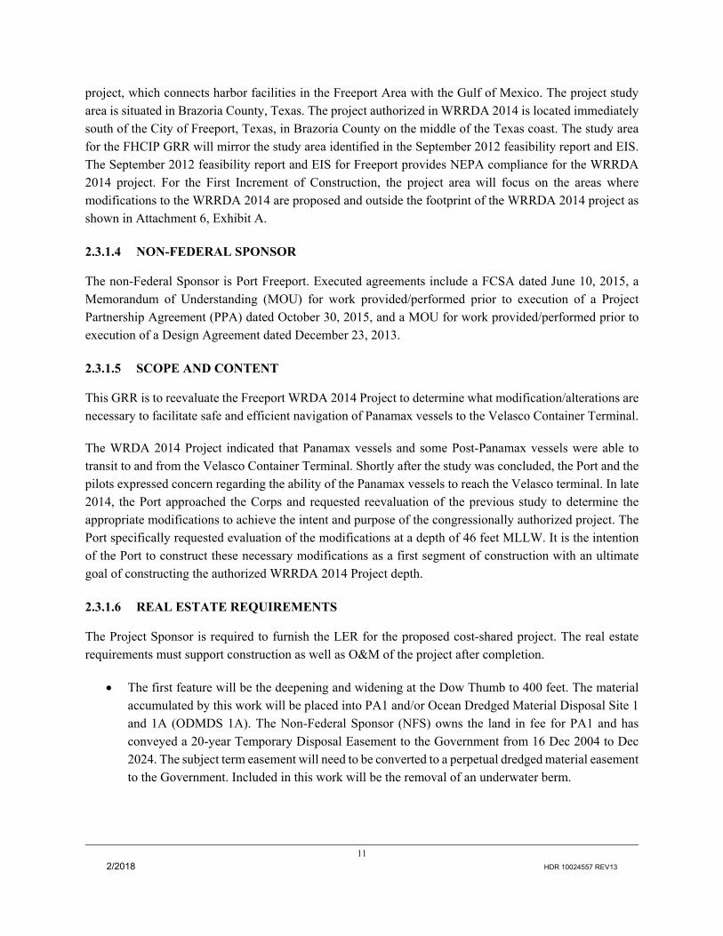
project, which connects harbor facilities in the Freeport Area with the Gulf of Mexico. The project study area is situated in Brazoria County, Texas. The project authorized in WRRDA 2014 is located immediately south of the City of Freeport, Texas, in Brazoria County on the middle of the Texas coast. The study area for the FHCIP GRR will mirror the study area identified in the September 2012 feasibility report and EIS. The September 2012 feasibility report and EIS for Freeport provides NEPA compliance for the WRRDA 2014 project. For the First Increment of Construction, the project area will focus on the areas where modifications to the WRRDA 2014 are proposed and outside the footprint of the WRRDA 2014 project as shown in Attachment 6, Exhibit A.
2.3.1.4 NON-FEDERAL SPONSOR
The non-Federal Sponsor is Port Freeport. Executed agreements include a FCSA dated June 10, 2015, a Memorandum of Understanding (MOU) for work provided/performed prior to execution of a Project Partnership Agreement (PPA) dated October 30, 2015, and a MOU for work provided/performed prior to execution of a Design Agreement dated December 23, 2013.
2.3.1.5 SCOPE AND CONTENT
This GRR is to reevaluate the Freeport WRDA 2014 Project to determine what modification/alterations are necessary to facilitate safe and efficient navigation of Panamax vessels to the Velasco Container Terminal.
The WRDA 2014 Project indicated that Panamax vessels and some Post-Panamax vessels were able to transit to and from the Velasco Container Terminal. Shortly after the study was concluded, the Port and the pilots expressed concern regarding the ability of the Panamax vessels to reach the Velasco terminal. In late 2014, the Port approached the Corps and requested reevaluation of the previous study to determine the appropriate modifications to achieve the intent and purpose of the congressionally authorized project. The Port specifically requested evaluation of the modifications at a depth of 46 feet MLLW. It is the intention of the Port to construct these necessary modifications as a first segment of construction with an ultimate goal of constructing the authorized WRRDA 2014 Project depth.
2.3.1.6 REAL ESTATE REQUIREMENTS
The Project Sponsor is required to furnish the LER for the proposed cost-shared project. The real estate requirements must support construction as well as O&M of the project after completion.
The first feature will be the deepening and widening at the Dow Thumb to 400 feet. The material accumulated by this work will be placed into PA1 and/or Ocean Dredged Material Disposal Site 1 and 1A (ODMDS 1A). The Non-Federal Sponsor (NFS) owns the land in fee for PA1 and has conveyed a 20-year Temporary Disposal Easement to the Government from 16 Dec 2004 to Dec 2024. The subject term easement will need to be converted to a perpetual dredged material easement to the Government. Included in this work will be the removal of an underwater berm.

12
2/2018 HDR 10024557 REV13
The second feature will consist of a bend easing just south of the Dow Thumb and east of the Phillip 66 facility. An estimated 10 acres of land will be cut away from two tracts owned by the NFS. The NFS owns the land in fee and will be required to convey a perpetual channel improvement easement to the Government. This material will be placed into PA1. This feature will also cut into the existing North Wave Barrier. This structure will need to be relocated and a new flood protection levee easement will need to be conveyed to Velasco Drainage for the right to operate and maintain the relocated wave barrier.
The third proposed feature will be the construction of a turning notch located at the upper turning basin. The material accumulated by this work will be placed into PA1. NFS owns the land in fee and will need to convey a perpetual dredged material easement to the Government.
2.3.1.6.1 PLACEMENT AREA 1 (PA1)
PA1 is approximately 320 acres and is located in Freeport roughly 0.5 mile south of State Highway 36 and approximately 1,000 feet east of the Brazos River Diversion Channel (USACE 2012a). The NFS owns the land in fee and has conveyed a 20-year Temporary Dredged Material Disposal Easement to the Government from 16 Dec 2004 to Dec 2024. The NFS will need to convey a Non-standard Perpetual Dredged Material Placement Easement to the Government.
2.3.1.6.2 PLACEMENT AREA 8 (PA8)
PA8 will be located in Freeport, north of Highway 36, and approximately 1,600 feet west of the Brazos River Diversion Channel (USACE 2012a). The PA is planned to be approximately 168 acres and is currently owned by the NFS. If PA8 is used, the NFS would need to convey a Non-standard Perpetual Dredged Material Placement Easement to the Government.
2.3.1.6.3 PLACEMENT AREA 9 (PA9)
According to USACE (2012a), PA9 is planned to be located in Freeport, north of Old State Highway 36, and approximately 300 feet west of the Brazos River Diversion Channel. The PA is planned to be approximately 250 acres with a perimeter length of approximately 14,000 linear feet. Assumed existing ground elevation is approximately 3 feet NAVD. According to USACE (2012b), a dike with a proposed height of approximately 30 feet NAVD is considered for PA9; this height includes 3 feet for ponding and freeboard above the targeted bulk dredged fill height. The tract on which PA9 was to be constructed is no longer owned in fee by Port Freeport and is owned in fee by Dow Chemical. However, it has been determined that based on the current O&M practices of all maintenance material from the FHC being placed into the ODMDS 1A (Maintenance ODMDS), PA9 is no longer necessary for the construction and O&M of the project. In the event that PA9 would have to be utilized, it will be the NFS’s responsibility to acquire the land in fee.

13
2/2018 HDR 10024557 REV13
2.3.1.6.4 OCEAN DREDGED MATERIAL DISPOSAL SITES 1 and 1A (ODMDS 1 and 1A)
Two ocean disposal sites located in the Gulf of Mexico exist for offshore placement. Both ODMDS sites are located in a dispersive offshore environment and assumed to have unlimited capacity due to longshore drift processes. The New Work ODMDS (ODMDS 1) is designed for an approximately 2,236-acre bottom area and is located approximately 5.5 miles southwest from the mouth of the Jetty Channel and approximately six miles from shore. The Maintenance ODMDS (ODMDS 1A) is designed for an approximately 1,129-acre bottom area and is located approximately 2.5 miles southwest from the mouth of the Jetty Channel and approximately 3 miles from shore. ODMDS 1A was not coordinated to be used by the full length of the FHC; however, under the purview of 40 CFR Part 228.14, maintenance material from the entire FHC is now coordinated for offshore placement (ODMDS 1A). This is the current O&M practice and the assumption for this project is that the current O&M practice of the ODMDS 1A placement for all FHC maintenance material will continue in the future.
Freeport Harbor Channel is a commercial navigation project in which the Federal Government has the responsibility of operating and maintaining the project after construction. Government responsibilities include, but are not limited to, dredging of the Federal project channel, assuring placement area capacity, and protecting the Government for environmental liabilities.
Maintenance dredging of the Federal Project channel is a 100% Federal responsibility and is accomplished through Federal dredging contracts. Perpetual easements conveyed to the Federal Government are needed to assure all project placement areas, which are built for the purpose of supporting the Federal navigation project, are available to the Government as often and for as long as they are needed to support the project. The Government is also responsible for managing the navigation project to assure sufficient placement area capacity exists to meet the needs of the Federal navigation project now and in the future.
Perpetual easements allow the Government to better restrict/control non-federal use, maximum quantities placed by non-federal interests, and remove any potential for interference with federal dredge contractors. Finally, the Government has certain Comprehensive Environmental Response, Compensation, and Liability Act (CERCLA) liabilities already as an operator and transporter of materials put into the placement area. Perpetual easements provide the property interest necessary for the Government to issue outgrants to non-federal users that will require testing and approval of non-federal dredged materials prior to placement into the Federal project placement areas, thus protecting the Government from additional CERCLA liability.
Based upon the above requirements to the non-standard perpetual easement estate, easement language below has been drafted for use in this project and submitted for approval in this report. Also listed is language to be used for the channel improvement easement, utility and/or pipeline easement and the flood protection levee easement.
No FATE modeling was performed as the GRR new work material is intended for placement at PA1 and offshore placement of O&M dredged material is already existing practice without major environmental concerns.

14
2/2018 HDR 10024557 REV13
2.3.1.6.5 ESTATES
“Non-Standard Perpetual Dredged Material Placement Easement”
A perpetual and assignable right and easement on, over, and across (the land described in Schedule A) (Tracts Nos. ________________,_______________, and _______________), for the location, construction, operation, maintenance and patrol of a dredged material disposal facility, including the right to borrow and/or deposit fill, spoil and dredged material thereon, the right to move, store and remove equipment and supplies, and the right to perform any other work necessary and incident to said facility, together with the right to trim, cut, fell, and remove therefrom all trees, underbrush, obstructions, and any vegetation, structures, or obstacles within the limits of the easement; reserving, however, to the landowners, their heirs and assigns, all such rights and privileges as may be used without interfering with or abridging the rights and easement hereby acquired; subject, however, to existing easements for public roads and highways, public utilities, railroads and pipelines.
“Channel Improvement Easement”
A perpetual and assignable right and easement to construct operate and maintain channel improvement works on, over and across (the land described in Schedule A) (Tract Nos. ____, ____ and ____) for the purposes as authorized by the Act of Congress approved ___________ , including the right to clear, cut, fell, remove and dispose of any and all timber, trees, underbrush, buildings, improvements and/or other obstructions therefrom; to excavate: dredge, cut away, and remove any or all of said land and to place thereon dredge or spoil material; and for such other purposes as may be required in connection with said work of improvement; reserving, however, to the owners, their heirs and assigns, all such rights and privileges as may be used without interfering with or abridging the rights and easement hereby acquired; subject, however, to existing easements for public roads and highways, public utilities, railroads and pipelines.
“Utility and/or Pipeline Easement”
A perpetual and assignable easement and right-of-way in, on, over and across (the land described in Schedule A) (Tracts Nos. _____,_____ and _____), for the location, construction, operation, maintenance, alteration; repair and patrol of (overhead) (underground) (specifically name type of utility or pipeline); together with the right to trim, cut, fell and remove therefrom all trees, underbrush, obstructions and other vegetation, structures, or obstacles within the limits of the right-of-way; reserving, however, to the landowners, their heirs and assigns, all such rights and privileges as may be used without interfering with or abridging the rights and easement hereby acquired; subject, however, to existing easements for public roads and highways, public utilities, railroads and pipelines.
“Flood Protection Levee Easement”
A perpetual and assignable right and easement in (the land described in Schedule A) (Tracts Nos, ____, ____ and ____) to construct, maintain, repair, operate, patrol and replace a flood protection (levee)

15
2/2018 HDR 10024557 REV13
(floodwall)(gate closure) (sandbag closure), including all appurtenances thereto; reserving, however, to the owners, their heirs and assigns, all such rights and privileges in the land as may be used without interfering with or abridging the rights and easement hereby acquired; subject, however, to existing easements for public roads and highways, public utilities, railroads and pipelines.
2.3.1.7 BORROW MATERIAL
The proposed project does not require any borrow material. All material needed for the construction of the placement area dikes will be borrowed from within the footprint of the proposed placement area.
2.3.1.8 ACCESS/STAGING AREA
The proposed plan alternatives do not require any Access/Staging Areas. Staging areas will be located on barges in navigable waters. All of the proposed work will be performed within the existing property owned by the sponsor and existing roads and highways within the project area. No credit will be allowed for access/staging areas since these areas fall within the boundary lines of the land acquired for the placement areas. The sponsor will get credit for the entire tract acquired for the required placement areas needed for the project.
2.3.1.9 RECREATION FEATURES
The proposed project does not have any recreation features.
2.3.1.10 INDUCED FLOODING
There will be no induced flooding by virtue of the construction of the project. The proposed project will be constructed within the existing R-O-W of the Freeport Harbor Channel.
2.3.1.11 FEDERALLY OWNED LAND AND EXISTING FEDERAL PROJECT
There is no federally owned land in the project area.
2.3.1.12 NAVIGATION SERVITUDE
Navigation Servitude emanated from the Commerce Clause of the Constitution of the United States, Article I; Section 8, Clause 3. The servitude gives the Federal Government the right to use the “Navigable Waters” of the United States without compensation for navigation projects. These are non-transferable rights, and are not considered interest in real property. The proposed project proposes to use two offshore placement areas located in navigable waters. Therefore, there is no real estate requirements associated with these sites.
2.3.1.13 PUBLIC LAW 91-646 RELOCATIONS
There are no residential houses, businesses, or farms that would be required for relocation associated with PL 91-646.

16
2/2018 HDR 10024557 REV13
2.3.1.14 ASSESSMENT OF PROJECT SPONSOR LAND ACQUISITION CAPABILITIES
The local sponsor, Port Freeport has the authority and capability to furnish lands, easements and rights of way in accordance with the Feasibility Cost-Sharing Agreement. The non-federal sponsor is highly capable of performing the real estate acquisition required by this project. An Assessment of NFS Land Acquisition Capabilities Survey was completed and shown in Attachment 6, Exhibit B but will be included in the final draft.
2.3.1.15 BASELINE COST ESTIMATE FOR REAL ESTATE
The costs listed in Attachment 6, Exhibit C reflect the estimated real estate costs for the proposed navigation project. Estimated costs include land payments (including mitigation site) authorized by LERRDs and administrative costs incidental to acquisition, for example surveying and mapping. SWG-RE was not able to obtain non-federal cost including conveyance of three perpetual easement, appraisal cost, administration cost and LERRD crediting cost. The baseline cost estimate is subject to change through final draft of this GRR.
2.3.1.16 ACQUISITION SCHEDULE
The acquisition of the LERRD necessary for the Project is the responsibility of the Non-Federal Sponsor, however, for the current project; the Sponsor owns all the lands required for the proposed plan. However, perpetual easements will need to be conveyed to the Government for the channel improvement feature and dredged material placement area. Details of the schedule for the conveyance of these easements will be develop prior to PED.
2.3.1.17 MINERAL ACTIVITY
Mineral title was not obtained for the review of third party mineral rights at the time of this report. SWG RE’s position for not obtaining mineral title is that the NFS has owned the lands in fee for PA1 and proposed PA8 for over 10 years without mineral extraction activity from third parties.
2.3.1.18 FACILITIES/UTILITIES/PIPELINES RELOCATION
There are 2 known pipelines crossing the channel, Freeport LNG is a recent permitted line already at the required depth (no relocation/removal) and Enbridge Power Corp. of which the Port has determined that no relocation/removal is required.
The bend easing project feature will impact the existing North Wave Barrier of the Freeport Hurricane Flood Protection System. This structure will need to be relocated and a new flood protection levee easement will need to be conveyed to Velasco Drainage for the right to operate and maintain the relocated levee. The cost for the relocation of the wave barrier will be included in the total project cost.

17
2/2018 HDR 10024557 REV13
2.3.1.19 HTRW OR OTHER ENVIRONMENTAL CONTAMINANTS
A HTRW assessment was conducted for Freeport WRRDA 2014 Project, in accordance with USACE document Engineering Regulation (ER) 1165-2-132. The assessment revealed that several HTRW sources exist at upland industries that line the banks of the Freeport Harbor Channel. Although these sources exist upland, no active enforcement actions were under way and no HTRW sites were located within the project area footprint.
2.3.1.20 ATTITUDES OF THE LANDOWNER
The Port of Freeport is the owner of all the project lands. As owners they are supportive and in favor of the project. No resistance to the project by the landowner is expected.
2.3.1.21 SPONSOR NOTIFICATION RISKS
An example of a letter notifying the NFS risk in acquiring lands prior to the signing Project Partnership Agreement (PPA) is shown in Attachment 6, Exhibit D.
2.3.2 AIDS TO NAVIGATION
All of the existing aids to navigation (ATON, or “aids”) for the channel will be adjusted as required. However, other aids affected by the plan, such as the reauthorized Stauffer Channel, will need to be evaluated during Preconstruction Engineering and Design phase.
2.3.3 ACCESS ROADS
All existing and proposed placement areas have existing access routes. Should they be given additional consideration, the new upland placement areas are basically configured on non-Federal sponsor–prescribed plats adjacent to the Brazos River and can be reached from existing access roads near these new areas. Additional access to project sites will be by water, with some sites only being accessible through waterborne equipment. No public roads require improvement for access to the project sites.
2.4 DREDGING TERMS
2.4.1 ADVANCE MAINTENANCE
Advance Maintenance (AM) consists of dredging deeper than the authorized channel dimensions to provide for the accumulation and storage of sediment. In critical and fast-shoaling areas, it is required to avoid frequent re-dredging and to ensure the reliability and least overall cost for operating and maintaining the project authorized dimensions. This Engineering Appendix considers an advanced maintenance of 2 feet for FHCIP GRR. This AM depth is 2 feet less than historical practice at Freeport Harbor.

18
2/2018 HDR 10024557 REV13
2.4.2 ALLOWABLE OVERDEPTH
An additional depth outside the required template is permitted to allow for inaccuracies in the dredging process. Districts may dredge a maximum of 2 feet of allowable overdepth in coastal regions and in inland navigation channels (ER 1130-2-520 Navigation and Dredging Operations and Maintenance Policies). This additional dredging allowance is referred to as a dredging tolerance, or allowable overdepth. The existing channel overdepth from offshore up to Station 82+66 is 2 feet and was assumed to remain constant for the proposed channel improvements. As the stationing increases upstream beyond Station 82+66, a 1-foot overdepth was assumed to match existing conditions. Because all project features are located beyond Station 82+66, this Engineering Appendix considers 1 feet of allowable overdepth for the FHCIP GRR, consistent with historical practice at Freeport Harbor, but it should be noted this is subject to change to 2 feet allowable overdepth based on future internal USACE O&M conditions or operational contract requirements.
2.4.3 PREDICTED SHOALING RATES
Annual shoaling rate at Freeport Harbor Channel (i.e. stations 71+52 to 184+20) was calculated as an arithmetic mean of historical maintenance dredged volumes. The calculated annual shoaling rate represents the annual maintenance dredging requirement for the No Action Alternative. An area factor was then calculated for each reach of the channel with proposed modifications and multiplied by annual shoaling rate for that reach to represent the likely annual shoaling rate for Alternative 2. The sedimentation analysis suggested that annual shoaling rate in Freeport Harbor Channel will increase from approximately 281,000 cy/year for the No Action Alternative to approximately 315,000 cy/year for Alternative 2, an increase of 12%. Additional details on the anticipated shoaling rates is presented in the Attachment 2, Hydrology and Hydraulics Report.
2.4.4 DREDGING FREQUENCY ASSUMPTIONS
The dredging cycle of a channel is defined by the average number of years between the O&M dredging operations for a historical period. Each channel has its own dredging frequency. The USACE, Galveston District’s Dredging Histories Database Management System contains this information for the Freeport Channel. The Entrance Channel, Jetty Channel and Lower Turning Basin (Sta -300+00 to Sta 78+52) currently have a dredging frequency of 1 year. The Freeport Harbor Channel (Sta 78+52 to Sta 184+20) currently has a dredging frequency of 3 years. It is assumed that the channel will retain this dredging frequency after the proposed modifications. Any maintenance dredging on the Stauffer Channel is assumed to occur with a frequency of 12 years. Maintenance dredging requirements are discussed in more detail in the Geotechnical Section of this Engineering Appendix.

19
2/2018 HDR 10024557 REV13
3 SURVEYING, MAPPING, AND OTHER GEOSPATIAL DATA REQUIREMENTS
3.1 SURVEYS
The survey data applied for this study are a mosaic of Lidar data obtained from the U.S. Geological Survey, and Lidar and bathymetry data provided by ERDC. The data provided by ERDC were originally compiled by ERDC for development of the STWAVE model prepared for the H&H portion of this study. The surveys were utilized to identify principal design features, volume estimates, impacts, and anomalies primarily associated in the vicinity of the Outer Bar and Jetty Channel and Main Channel reaches. Recent color orthodigital aerial photographs were utilized to help identify existing topographical features such as shoreline, docks, creeks, potential upland PA sites, wooded areas, etc. Additional land elevations were implied from the orthodigital maps, and from the available Lidar data (dated 2006) obtained from the U.S Geological Survey. The bathymetric data provided by ERDC were obtained from Chris Massey, Research Mathematician, ERDC-CHL on 8/24/2015.When applicable, interpolation between hydro-surveys and land surveys was performed using a 3D surface generated in AutoCAD.
3.2 VERTICAL DATUM
All elevations referred to in this report, unless specifically noted otherwise, are based on the Mean Lower Low Water (MLLW) tidal datum. Previous publications on this project were released utilizing Galveston District’s local mean low tide (MLT) datum. A conversion of 0 MLLW = +1 feet MLT (which is rounded to the nearest whole foot) has been applied.
3.3 HORIZONTAL DATUM
The North American Datum of 1983 (NAD 83) was applied for this assessment. Drawings are shown in NAD 83, Texas State Plane Coordinate System, South Central Zone.
3.4 TIDAL DATUM
Army regulations and Headquarters, USACE (HQUSACE) guidance on tidal datum, provided in Engineering Technical Letter (ETL) 1110-2-349 REQUIREMENTS AND PROCEDURES FOR REFERENCING COASTAL NAVIGATION PROJECTS TO MEAN LOWER LOW WATER DATUM, dated 1 April 1993, and Engineering Manual (EM) 1110-2-1003, 1 April 2002, stress the necessity of converting local datum such as MLT to MLLW. EM 1110-2-1003 further states that MLLW should be tied to the North American Vertical Datum of 1988 (NAVD). The predominant reasons for conversion to MLLW are the need for consistency throughout the ports of the U.S., to enhance the continuity of National Oceanic and Atmospheric Administration (NOAA) and Coast Guard navigation charts, and to avoid misconceptions within the shipping and dredging industries with regard to channel depths.

20
2/2018 HDR 10024557 REV13
3.5 TIDAL DATUM CONVERSION
The Galveston District has an established survey control network along the Freeport Harbor Channel. To comply with the above-referenced guidance on referencing tidal datums using MLLW, the Galveston District obtained vertical survey measurements at tide gages and benchmarks to estimate the relative difference between MLT and MLLW datums along the Freeport Channel. The objective was to maintain an Effective Water Depth of 46 feet while correctly referencing resulting water surface level in MLLW as shown on the following figure.
Figure 5 Datum Conversion for Freeport Harbor Channel.
At Freeport Channel, datum values for MLLW are approximately +1 above MLT. However, this does not result in increased water depth. The actual water depths are equivalent between a 45-foot MLT channel template and a 46-foot MLLW channel template.

21
2/2018 HDR 10024557 REV13
4 GEOTECHNICAL
4.1 PURPOSE
This section provides supporting geotechnical information for the FHCIP’s GRR Project, including modifications to the channel around the Dow Thumb and distribution of dredged material to the upland placement areas (Placement Area 1 and 8). Engineering analysis to support the design proposal to modify channel dimensions of the Dow Thumb Waist area used historical soils information, no new soils investigations were taken as part of this project.
4.2 PROJECT CONDITIONS
4.2.1 GENERAL GEOLOGY
The Dow Thumb area is situated in the eastern portion of the Colorado-Brazos deltaic plain. These formations consist of sediments deposited during the Cenozoic era. Heavy calcareous clays with interbedded silt and sand strata, Pleistocene in age, underlie the recent sediments.
4.2.2 SOILS INVESTIGATION
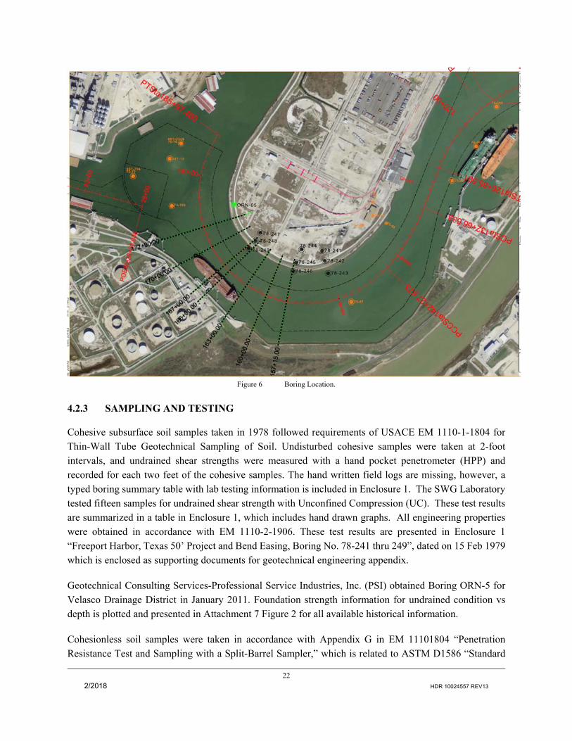
Dow Thumb historical subsurface soil investigation locations are shown below. Boring logs and test information are enclosed with this appendix see Attachment 7 Enclosure 1 titled: “REPORT OF SOIL TESTS FREEPORT HARBOR, TEXAS 50’ PROJECT AND BEND EASING BORING NO. 78-241 thru 249.” SWG obtained borings 78-241 through 78-249 in 1978. Velasco Drainage District obtained boring ORN-05 in 2005 in Enclosure 2 titled: “Velasco Drainage District Levee Evaluation Report” in July 2011. Boring depths range from 40 to 60 feet below natural ground MLT, or 41 to 61 feet below natural ground MLLW. These historical borings are located in close enough proximity to provide relevant information for this project. Test results from the 2005 boring are typically consistent with test results from the 1978 borings.
22
2/2018 HDR 10024557 REV13
Figure 6 Boring Location.
4.2.3 SAMPLING AND TESTING
Cohesive subsurface soil samples taken in 1978 followed requirements of USACE EM 1110-1-1804 for Thin-Wall Tube Geotechnical Sampling of Soil. Undisturbed cohesive samples were taken at 2-foot intervals, and undrained shear strengths were measured with a hand pocket penetrometer (HPP) and recorded for each two feet of the cohesive samples. The hand written field logs are missing, however, a typed boring summary table with lab testing information is included in Enclosure 1. The SWG Laboratory tested fifteen samples for undrained shear strength with Unconfined Compression (UC). These test results are summarized in a table in Enclosure 1, which includes hand drawn graphs. All engineering properties were obtained in accordance with EM 1110-2-1906. These test results are presented in Enclosure 1 “Freeport Harbor, Texas 50’ Project and Bend Easing, Boring No. 78-241 thru 249”, dated on 15 Feb 1979 which is enclosed as supporting documents for geotechnical engineering appendix.
Geotechnical Consulting Services-Professional Service Industries, Inc. (PSI) obtained Boring ORN-5 for Velasco Drainage District in January 2011. Foundation strength information for undrained condition vs depth is plotted and presented in Attachment 7 Figure 2 for all available historical information.
Cohesionless soil samples were taken in accordance with Appendix G in EM 11101804 “Penetration Resistance Test and Sampling with a Split-Barrel Sampler,” which is related to ASTM D1586 “Standard

23
2/2018 HDR 10024557 REV13
Penetration Test (SPT) and Split-Barrel Sampling of Soils.” SPT blowcount numbers are normalized in accordance with equation 3-2, (N60 = CER*Cn*Nspt) friction angle is estimated in accordance with TABLE 3-1, b. “Relative Density and In Situ Soil Tests” in EM 1110-1-1905.
4.2.4 SLOPE STABILITY ANALYSES
The Freeport Hurricane Flood Protection Levee (FHFPL) was constructed immediately adjacent to the existing Freeport Navigation Channel around the Dow Thumb. The north slope of the navigation channel in this area acts as the toe of the FHFPL and is technically, the previous ship channel (-39 feet) prior to being shifted away from the Dow Thumb during the construction of the 46-foot project in the 1990s. It is a land mass consisting of naturally deposited sediments and not a constructed feature. For purposes of this discussion and consistence with the document we will refer to this feature as the underwater berm. To facilitate widening the channel in this area the engineering team evaluated removal of part of this underwater berm, computing slope stability analysis without it.
The factor of safety according to page C-2 in EM 1110-2-1902 is defined with respect to the shear strength of the soil as:
F = s/ τ, (C-1)
s = the available shear strength or resisting moment τ = shear stress required for equilibrium or overturning moment
The stability analysis considered both drained and undrained conditions. The majority of undrained shear strengths of cohesive soil values came from hand pocket penetrometer measurements and unconfined compression values obtained from the 1978 investigations. Slope stability analyses computed by Geostudio computed over thousands of slip circles for each cross section soil. Only the lowest 20 to 30 factors of safety were plotted for the presentation in Attachment 7 Figure 3 through Figure 13. A few unconsolidated-undrained triaxial compression tests of boring ORN-05 were obtained through Velasco’s Drainage District’s 2005 investigation. The boring ORN-05 is located near station 176+00 and the undrained shear strength information obtained from this boring was analyzed with SWG historical soil information for the slope stability, (see Attachment 7 Figure 7 through Figure 9). Attachment 7 Figure 7 and Figure 9 represent the foundation soil shear strength at the narrowest channel area. These shear strength are computed and averaged according to boring ORN-05, 78-247, 78-248, and 78-249 and correlated to soil stratum with its elevations. Attachment 7 Figure 8 and Figure 9 show the lowest of factor of safety of undrained and drained condition in the region of station 166+00 to station 170+00. The slope stability analyses of drained condition of station 150+00 and station 157+00 were not performed because the information to estimate the frictional angles was not available. Based on the past performance of the channel slope at Dow Thumb, the SWG geotechnical team believes the critical state is associated with the end of construction of the channel widening project. Drained strength of cohesive materials were obtained with Plasticity Index (PI) vs Effective Friction Angle, as shown on Figure 3-2 in EM 1110-2-1913. Friction angles of cohesionless soil were estimated in accordance with EM 1110-1-1905. Specific unit weights of soils were computed based on the SWG lab report using percentages of moisture content and dry densities. The value for unit weight

24
2/2018 HDR 10024557 REV13
of soils were obtained by averaging the results within a same strata. Three cross section soil profiles were analyzed, using GeoStudio 2012 Slope/W and the Morgenstern-Price and Spencer methods to compute the slope stability. In order to determine the effect a tension crack would have on the stability, a tension crack depth was computed and found to be 10.59 feet according to equation C-36 in EM 1110-2-1902. Slope stability with tension crack analyses are performed and presented in the geotechnical attachment. The Factor of Safety of slope stability analyses are shown in Table 3. The analysis results are enclosed in Attachment 7 from Figure 3 through Figure 13.
Table 3 Slope Stability Analyses Results.
Cross Section Stations
Factor of Safety of Undrained Condition with Berm (Without tension crack/with tension crack)
Factor of Safety of Undrained Condition without Underwater Berm (Without tension crack/with tension crack)
Factor of Safety of Drained Condition with Underwater Berm (current condition) (Without tension crack/with tension crack)
Sta. 150+00 1.343/1.146 1.014/0.848 N/A* Sta. 157+00 1.039 /0.988 1.015/0.915 N/A* Sat. 170+00 1.255/1.155 1.057/0.983 1.407 /1.481 *Insufficient drained soil information was available
Based on the available foundation strength information from 1978 soils investigation, the computed factor of safety at the end of excavating the underwater berm construction is about 1 which is much lower than EM 1110-2-1902 and EM 1110-2-1913 recommended value of 1.3. The strength information from 1978 investigation provided only very rough estimates which are largely based hand pocket penetrometer measurements from field logs and a few unconfined compression tests. To widen the Dow Thumb for navigation, removal of the underwater berm is necessary, however with degrees of uncertainty associated with foundation material information, SWG PDT believes the factor of safety is about 1 for the undrained condition. Discussions with the SWG Levee Safety Program indicated that if the Navigation project impacts the levee stability, than the Navigation project must implement engineering solutions to make the Flood Risk Management project whole, by bringing the levee up to an acceptable factor of safety (>1.3), which based upon existing data, would be above the current factor of safety. The SWG PDT believes it is appropriate to propose solutions which will enable widening of Dow Thumb and increase of the factor of safety for the flood protection levee.
4.3 ENGINEERING PROPOSAL
Removal of the underwater berm is the Recommended Plan to allow a larger vessel to pass the Dow Thumb area. To facilitate this plan, this project considered two methods to allow removal of the underwater berm while increasing the factor of safety for the FHFPL. The first is to provide foundation reinforcing using ASTM A572 hot rolled steel Pipe-PZ or Pipe-AZ combined system. This is an off the shelf product which is available from multiple steel suppliers. Preliminary slope stability analysis demonstrates a possibility of

25
2/2018 HDR 10024557 REV13
increasing the factor of safety to 1.518 at station 150+00, 2.130 at station 157+00 and 1.687 at station 166+00 to station 170+00 by using this combined system to -55 feet MLLW.
The second method is to reinforce the soft foundation materials with deep soil mixing. The foundation materials are non-homogenous, therefore this method considered using cement and/or lime for the soft clay layers and cement for the loose sand layers. The stability analysis indicated that the factor of safety could increase to 1.681 from soil mixing to 55 feet below 0’ elevation. However in order to stabilize the foundation of the levee, the deep soil mixing will be required to achieve a very high shear strength which may not be possible due to the site foundation soil condition, required longer curing time, and could be very expensive.
Slope stability analyses for both methods are included in Attachment 7 Figure 10 through Figure 13. The values used for these analyses are from historical soil investigations in the area. Further foundation investigation and detailed design analyses are required in order to prepare plans and specification for final designs and ultimately construction.
4.4 CONSTRUCTION SEQUENCES
Due to slope stability concerns, the foundation reinforcement shall be constructed before the underwater berm is removed.
4.5 CONSTRUCTION CONCERNS
Further foundation investigation in the immediate area of the Dow Thumb are required to better estimate soil parameters. These investigations should be done during PED or in a separate NFS modification, and will allow more accurate stability analyses to be performed. Concerns at this time are:
1. Lack of soil data quality due to the missing and/or low precision methods to determine soil strength.
2. Constraints to a possible deepening and widening in the future. 3. Obstruction of the navigation channel during construction. 4. Ground vibrations produced by pile driving may impact the petrochemical industry nearby. 5. Limited site accessibility for heavy construction equipment. 6. Soil mixing may be impractical due to soil stratification with cohesive materials.
4.6 DREDGED MATERIAL MANAGEMENT PLAN
A Dredged Material Management Plan (DMMP) was established to develop a placement plan that will accommodate the placement of new work and maintenance dredged material over 50 years associated with the FHCIP GRR. Dredged material management planning for all Federal harbor projects is conducted by USACE to ensure that dredging activities are performed in an environmentally acceptable manner, use sound engineering techniques, are economically justified, and to ensure that long-term placement facilities are available. Ultimately, the DMMP identifies specific measures necessary to manage the volume of

26
2/2018 HDR 10024557 REV13
material likely to be dredged within the FHCIP project over the 50-year period of analysis included in the GRR.
This DMMP considers maintenance and new work dredging volume associated with the FHCIP GRR including: Existing channel to 46 feet MLLW; Proposed Turning Notch, Channel Widening, and Bend Easing to 46 feet MLLW. All new work dredging has an advanced maintenance depth of 2 feet and an allowable overdepth of 1 foot.
4.6.1 PLACEMENT AREAS
Dredged material placement areas near Freeport Harbor are shown in Figure 7. The Maintenance Ocean Dredged Material Disposal Site (ODMDS 1A) and Placement Area 1 (PA1) are being considered as potential disposal sites in this DMMP. With the recommendation that all maintenance material be placed in the ODMDS, the overall volume of sediment requiring upland confined storage drops dramatically.
As outlined in more detail below, both offshore and upland placement alternatives were evaluated for placement of maintenance material. These evaluations indicated that offshore placement would be more cost effective and have less environmental impacts based on Section 404(b)(1) criteria (no impacts to land previously identified as PA 9). In addition, placement of maintenance material offshore is already standard operating procedure for Freeport Channel. As a result, for the purposes of this DMMP use of PA8 and PA9 is not foreseen within the 50-year planning horizon.

27
2/2018 HDR 10024557 REV13
Figure 7 Dredged Material Placement Areas at Freeport Harbor.
4.6.1.1 MAINTENANCE OCEAN DREDGED MATERIAL DISPOSAL SITE (ODMDS 1A)
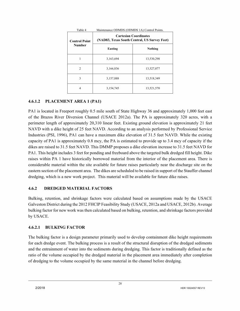
The maintenance ODMDS (ODMDS 1A) is located in the Gulf of Mexico, approximately 2.5 miles southwest from the mouth of the Jetty Channel and approximately 3 miles from shore. The site is located in a dispersive offshore environment with approximately 1,129 acres of bottom area. Due to its dispersive nature, the site can be assumed to have unlimited capacity. Coordinates of control points for the Maintenance ODMDS are presented in Table 4. The maintenance ODMDS was coordinated for only a portion of the channel. However, recent coordination, 40 CFR 228.15 allows material from the entire channel to be placed offshore in ODMDS 1A.
28
2/2018 HDR 10024557 REV13
Table 4 Maintenance ODMDS (ODMDS 1A) Control Points.
Control Point Number
Cartesian Coordinates (NAD83, Texas South Central, US Survey Feet)
Easting Nothing
1 3,163,694 13,530,298
2 3,166,836 13,527,077
3 3,157,888 13,518,349
4 3,154,745 13,521,570
4.6.1.2 PLACEMENT AREA 1 (PA1)
PA1 is located in Freeport roughly 0.5 mile south of State Highway 36 and approximately 1,000 feet east of the Brazos River Diversion Channel (USACE 2012a). The PA is approximately 320 acres, with a perimeter length of approximately 20,310 linear feet. Existing ground elevation is approximately 21 feet NAVD with a dike height of 25 feet NAVD. According to an analysis performed by Professional Service Industries (PSI, 1996), PA1 can have a maximum dike elevation of 31.5 feet NAVD. While the existing capacity of PA1 is approximately 0.8 mcy, the PA is estimated to provide up to 3.4 mcy of capacity if the dikes are raised to 31.5 feet NAVD. This DMMP proposes a dike elevation increase to 31.5 feet NAVD for PA1. This height includes 3 feet for ponding and freeboard above the targeted bulk dredged fill height. Dike raises within PA 1 have historically borrowed material from the interior of the placement area. There is considerable material within the site available for future raises particularly near the discharge site on the eastern section of the placement area. The dikes are scheduled to be raised in support of the Stauffer channel dredging, which is a new work project. This material will be available for future dike raises.
4.6.2 DREDGED MATERIAL FACTORS
Bulking, retention, and shrinkage factors were calculated based on assumptions made by the USACE Galveston District during the 2012 FHCIP Feasibility Study (USACE, 2012a and USACE, 2012b). Average bulking factor for new work was then calculated based on bulking, retention, and shrinkage factors provided by USACE.
4.6.2.1 BULKING FACTOR
The bulking factor is a design parameter primarily used to develop containment dike height requirements for each dredge event. The bulking process is a result of the structural disruption of the dredged sediments and the entrainment of water into the sediments during dredging. This factor is traditionally defined as the ratio of the volume occupied by the dredged material in the placement area immediately after completion of dredging to the volume occupied by the same material in the channel before dredging.

29
2/2018 HDR 10024557 REV13
Bulking Factor = (Volume of Material in Placement Area)
(Volume of Material in Channel prior to Dredging)
The amount of bulking varies with the type of sediments and the method of dredging (mechanical or
hydraulic). Other factors that affect bulking include size of dredge, horsepower, and residence time in the
pipeline. For this project, dredging will primarily be conducted hydraulically. The new work dredging for
this project will consist of about 80 to 90 percent clays (of primarily stiff consistency with some traces of
silts or clayey silts), and about 10 to 20 percent sands of various densities, based on available boring data
from the Upper Turning Basin on out to sea.
Development of containment dike height requirements on this project was based on a bulking factor of about 1.3 for maintenance material and about 2 for the portion of new work material anticipated to go into a slurry state before final discharge at the disposal sites. The remaining portion of new work material that will come out of the dredge pipe in the form of solid clay fragments (informally referred to as “clay balls”) or segregate from the dredge mixture soon after discharge (such as sands) is anticipated to remain fairly close to the original density from the channel.
4.6.2.2 RETENTION FACTOR
For calculations and quantities produced on this project, the definition adopted for the term “retention factor” is the fraction of new work material from the channel that, when dredged to the site, retains a degree of consistency from the original in situ state. These materials can then be used as fill materials for containment dike foundation construction or future borrow for future mechanical containment dike construction. When pumped to the site the clay balls and sand tend to accumulate or stack within the general vicinity of the end of the dredge pipe
Retention Factor = (Volume of Dredged Material Suitable for Containment Dike Fill Material)
(Annual Dredging Quantity)
Variables that can influence this factor include in situ material properties and consistencies, size of the dredge, type and control of cutter head, horsepower, and pump distance. For feasibility level, a retention factor of about 0.5 was assumed for this project.
4.6.2.3 SHRINKAGE FACTOR
The shrinkage factor is a design parameter used to evaluate the long-term storage capacity of a PA for use in developing the DMMP. It is defined as the ratio of the long-term volume occupied by a certain quantity of dredged material in a PA, to the volume it occupied in the channel prior to dredging. Generally, this parameter is associated with maintenance material, but may also be associated with new work material.
Shrinkage Factor = (Long-term Volume in Disposal Area)
(Volume in Channel Prior to Dredging)
Items that affect the shrinkage include the soil composition, pan evaporation rate, consolidation,

30
2/2018 HDR 10024557 REV13
desiccation, climatological conditions, drainage efficiency or dewatering measures implemented, and dredging schedule of maintenance material placed at the sites. Determination of a precise shrinkage factor for a placement area can be a complex task and include modeling the consolidation and desiccation shrinkage based on laboratory test data, climatological data, drainage characteristics, and operational characteristics. For feasibility level, the development of the long-term storage capacity and containment dike height requirements on this project was based on a shrinkage factor of about 0.65 for maintenance material
4.6.2.4 NEW WORK AVERAGE BULKING FACTOR
Assuming 85% clay and 15% sand and given the retention factor of 0.5 and the bulking factor of 2.0, it is expected that 50% of the clay material would expand by a factor of 2.0 while the rest of the clay and all the sand would retain their in situ density. This leads to a new work average bulking factor of 1.425 for placement. In other words, for the purpose of placement calculations, it is expected that the new work material would expand by a factor of 1.425.
For long term calculations, when the shrinkage factor of 0.65 is applied to the bulked clay material, it leads to a new work average bulking factor of 1.13. In other words, for the purpose of long term PA capacity calculations, it is expected that the new work material would expand by a factor of 1.13.
4.6.3 DREDGED MATERIAL CLASSIFICATION
New work dredged material to be removed for the FHCIP GRR is assumed to have consistent composition with the classification provided in the 2012 FHCIP Feasibility Study. The new work is expected to consist of 10-20 percent sand and 80-90 percent clay. Due to lack of boring data, soil classification was not performed for the new work on the Stauffer Channel.
4.6.4 DREDGED MATERIAL QUANTITIES
The quantity of new work material for the proposed GRR widening at Freeport Harbor to achieve Alternative 2 at the Freeport Harbor Channel is approximately 1.734 mcy (see Table 5). The quantities were determined using the average end area method.
The quantity of maintenance material to be removed over 50 years for the channel and the GRR improvements at -46 feet MLLW, is estimated to be 15.3 mcy, as presented in Table 6. After the completion of new work dredging for the Freeport GRR and the Lower Stauffer Channel, the project will require periodic maintenance dredging to retain navigability. It is estimated that the Freeport Harbor Channel (Stations 71+52 to 184+20) will receive an annual shoaling volume of approximately 315,000 cy (HDR, 2016) pursuant to the implementation of the GRR features. Additionally, it is estimated that the Lower Stauffer Channel will receive an annual shoaling rate of approximately 2,500 cy. This DMMP is based on maintenance dredging in 3-year cycles for reaches below Station 184+20 and 12-year cycles for reaches above Station 184+20, resulting in a total dredged volume of approximately 15.3 mcy. All maintenance dredged material is designated for placement at the Maintenance ODMDS. .
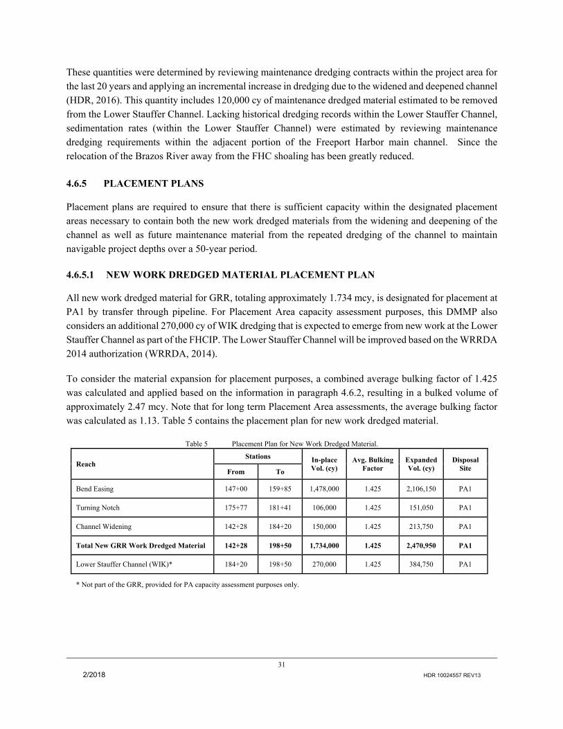
31
2/2018 HDR 10024557 REV13
These quantities were determined by reviewing maintenance dredging contracts within the project area for the last 20 years and applying an incremental increase in dredging due to the widened and deepened channel (HDR, 2016). This quantity includes 120,000 cy of maintenance dredged material estimated to be removed from the Lower Stauffer Channel. Lacking historical dredging records within the Lower Stauffer Channel, sedimentation rates (within the Lower Stauffer Channel) were estimated by reviewing maintenance dredging requirements within the adjacent portion of the Freeport Harbor main channel. Since the relocation of the Brazos River away from the FHC shoaling has been greatly reduced.
4.6.5 PLACEMENT PLANS
Placement plans are required to ensure that there is sufficient capacity within the designated placement areas necessary to contain both the new work dredged materials from the widening and deepening of the channel as well as future maintenance material from the repeated dredging of the channel to maintain navigable project depths over a 50-year period.
4.6.5.1 NEW WORK DREDGED MATERIAL PLACEMENT PLAN
All new work dredged material for GRR, totaling approximately 1.734 mcy, is designated for placement at PA1 by transfer through pipeline. For Placement Area capacity assessment purposes, this DMMP also considers an additional 270,000 cy of WIK dredging that is expected to emerge from new work at the Lower Stauffer Channel as part of the FHCIP. The Lower Stauffer Channel will be improved based on the WRRDA 2014 authorization (WRRDA, 2014).
To consider the material expansion for placement purposes, a combined average bulking factor of 1.425 was calculated and applied based on the information in paragraph 4.6.2, resulting in a bulked volume of approximately 2.47 mcy. Note that for long term Placement Area assessments, the average bulking factor was calculated as 1.13. Table 5 contains the placement plan for new work dredged material.
Table 5 Placement Plan for New Work Dredged Material.
Reach Stations In-place
Vol. (cy) Avg. Bulking
Factor Expanded Vol. (cy)
Disposal Site From To
Bend Easing 147+00 159+85 1,478,000 1.425 2,106,150 PA1
Turning Notch 175+77 181+41 106,000 1.425 151,050 PA1
Channel Widening 142+28 184+20 150,000 1.425 213,750 PA1
Total New GRR Work Dredged Material 142+28 198+50 1,734,000 1.425 2,470,950 PA1
Lower Stauffer Channel (WIK)* 184+20 198+50 270,000 1.425 384,750 PA1
* Not part of the GRR, provided for PA capacity assessment purposes only.
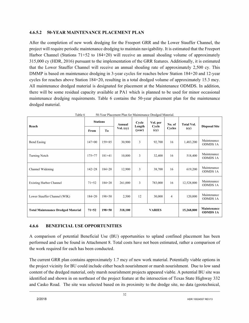
32
2/2018 HDR 10024557 REV13
4.6.5.2 50-YEAR MAINTENANCE PLACEMENT PLAN
After the completion of new work dredging for the Freeport GRR and the Lower Stauffer Channel, the project will require periodic maintenance dredging to maintain navigability. It is estimated that the Freeport Harbor Channel (Stations 71+52 to 184+20) will receive an annual shoaling volume of approximately 315,000 cy (HDR, 2016) pursuant to the implementation of the GRR features. Additionally, it is estimated that the Lower Stauffer Channel will receive an annual shoaling rate of approximately 2,500 cy. This DMMP is based on maintenance dredging in 3-year cycles for reaches below Station 184+20 and 12-year cycles for reaches above Station 184+20, resulting in a total dredged volume of approximately 15.3 mcy. All maintenance dredged material is designated for placement at the Maintenance ODMDS. In addition, there will be some residual capacity available at PA1 which is planned to be used for minor occasional maintenance dredging requirements. Table 6 contains the 50-year placement plan for the maintenance dredged material.
Table 6 50-Year Placement Plan for Maintenance Dredged Material.
Reach
Stations Annual Vol. (cy)
Cycle Length (year)
Vol. per Cycle (cy)
No. of Cycles
Total Vol. (cy)
Disposal Site From To
Bend Easing 147+00 159+85 30,900 3 92,700 16 1,483,200 Maintenance ODMDS 1A
Turning Notch 175+77 181+41 10,800 3 32,400 16 518,400 Maintenance ODMDS 1A
Channel Widening 142+28 184+20 12,900 3 38,700 16 619,200 Maintenance ODMDS 1A
Existing Harbor Channel 71+52 184+20 261,000 3 783,000 16 12,528,000 Maintenance ODMDS 1A
Lower Stauffer Channel (WIK) 184+20 198+50 2,500 12 30,000 4 120,000 Maintenance ODMDS 1A
Total Maintenance Dredged Material 71+52 198+50 318,100 VARIES 15,268,800 Maintenance ODMDS 1A
4.6.6 BENEFICIAL USE OPPORTUNITIES
A comparison of potential Beneficial Use (BU) opportunities to upland confined placement has been performed and can be found in Attachment 8. Total costs have not been estimated, rather a comparison of the work required for each has been conducted.
The current GRR plan contains approximately 1.7 mcy of new work material. Potentially viable options in the project vicinity for BU could include either beach nourishment or marsh nourishment. Due to low sand content of the dredged material, only marsh nourishment projects appeared viable. A potential BU site was identified and shown in on northeast of the project feature at the intersection of Texas State Highway 332 and Casko Road. The site was selected based on its proximity to the dredge site, no data (geotechnical,

33
2/2018 HDR 10024557 REV13
biological or survey) information has been collected and very limited real estate coordination has been conducted for the site. Amid the unknown existing elevation within the BU site, an average fill height of 3 feet was assumed. Based on this fill height the potential BU site can contain roughly 0.7 mcy of dredged material. The BU site does not have sufficient area to hold all 1.7 mcy of new work material; therefore, the remaining 1.0 mcy of new work material needs to be placed at PA1. A natural meandering channel, currently passes through the BU site. In order to retain the existing channel, the BU site was split in to two (2) parcels. A map of the potential BU site is presented in Figure 8
Figure 8 Project features, placement area, and potential BU site. *Note: Dredge pipeline routes are assumed and may differ with actual pipeline routes.
The work required for each scenario (i.e. upland placement vs beneficial use) was estimated by listing all of the necessary activities for placement of the estimate 1.7 mcy of new work material. Table 7 and Table 8 contain an itemized list of the required work for each case.

34
2/2018 HDR 10024557 REV13
Table 7 Work Estimate for Disposal of All Material in PA1.

35
2/2018 HDR 10024557 REV13
Table 8 Work Estimate for Including Beneficial Use of Dredged Material.

36
2/2018 HDR 10024557 REV13
Table 9 compares the required work which effectively translates into cost requirements for the purpose of this comparison.
Table 9 Required Work/Cost Comparison
After a careful consideration and comparison of the required work and specifics to construct the placement area and to discharge the material, it has been determined that the placement of the entire 1.7 mcy of new work into PA 1 would be the least cost placement alternative. While the BU site is a potential placement area it cannot handle the required volume, nor is there any other potential BU area in the proximity for use. Additionally, the cost for acquiring the land for the BU, if able to do so, would likely greatly exceed the cost associated with PA1.
Metric Upland Placement (PA 1)
Least
Cost
Benefical Use Placement
(BU) & PA 1
Sufficent Capacity Yes n/a
No, identified BU site can only hold 0.7 MCYs
additional non-BU site required. PDT was not able to identify another BU site in
proximity. Construction Surveys One PA 1 Two
PA/BU Constructing Moblization and Demobilzation
Once PA 1Twice (For BU and again for
PA 1)Dredge Mobilization and
DemobilizationOnce Same Once
Pipeline Mobilization and Demobilization
Once PA 1Twice (For BU and again to
PA 1)
Pumping Distance 2.3 miles PA 1
.7 MCY for 2.7 miles to BU site and 1 MCY PA 1 for 2.3
miles to PA 1 = (2.5 miles weighted average)
New Decant Structures No, existing PA 1 Yes, five (5) for BU Site
Sensitive ResourcesNone remaining, covered by
previous EA/EISPA 1
No evaluation of resources conducted on BU Site, not
necessary on PA 1,
Geotechnical Surveys Conducted and Completed PA 1None existing on BU Site, will require investigation
Real Estate EasementExisting Easement owned by
NFS PA 1
No easement on BU Site, underlaying land owned by multiple non-NFS entities
PA 1 Levee Raising (CYs) 170,000 BU 165,000
Marsh Levee Raising (CYs) 0 PA 1 90,000
Bankline Stabilization No PA 1 Yes
Least Cost Placement Alternative YES *** NO
37
2/2018 HDR 10024557 REV13
5 ENVIRONMENTAL ENGINEERING
5.1 ENVIRONMENTALLY RENEWABLE MATERIALS
Not Applicable
5.2 DESIGN OF POSITIVE ENVIRONMENTAL ATTRIBUTES INTO THE PROJECT
Potential environmental attributes for this project include increasing navigational efficiency of vessels using the channel, increasing ability of the channel to safely accommodate larger vessels, and beneficially using sediments from channel modifications and maintenance for environmental restoration.
5.3 INCLUSION OF ENVIRONMENTALLY BENEFICIAL OPERATIONS AND
MANAGEMENT FOR THE PROJECT
Creation of new placement areas are not needed for this project. The operation and maintenance plan consisted of utilizing existing placement areas. Site monitoring and management plans for disposal are necessary to ensure proper management of sites, to minimize the potential for adverse environmental impacts, and to ensure compliance with laws, regulations and permits.
5.4 BENEFICIAL USES OF SPOIL OR OTHER PROJECT REFUSE DURING
CONSTRUCTION AND OPERATION
The beneficial use of dredged material was considered as described in paragraph 4.6.6.
5.5 ENERGY SAVINGS FEATURES OF THE DESIGN
Energy saving features of the design include decreasing pumping distances between dredge vessels and the placement areas. This reduces the load on the pump and minimizes the amount of fuel needed.
5.6 MAINTENANCE OF THE ECOLOGICAL CONTINUITY IN THE PROJECT WITH THE
SURROUNDING AREA AND WITHIN THE REGION
The ecological continuity in the project with the surrounding area and within the region should not be interrupted permanently with the current dredging and material placement plans.
5.7 CONSIDERATION OF INDIRECT ENVIRONMENTAL COSTS AND BENEFITS
Indirect environmental costs were considered in the improvement project. The water quality may be affected by turbidity and the exhaust from the dredge during construction, and future maintenance may have a minor degrading effect on air quality. Indirect benefits considered are the decreased risk of adverse impacts to the environment from vessel accidents.
38
2/2018 HDR 10024557 REV13
5.8 INTEGRATION OF ENVIRONMENTAL SENSITIVITY INTO ALL ASPECTS OF THE
PROJECT
Consideration and coordination has been given to environmental, social and economic effects of the proposed project modifications in accordance with the National Environmental Policy Act (NEPA) in all aspects of the project.
Best management practices (BMPs) will be adopted to avoid inadvertent impacts to wildlife during construction. Specific measures will include avoiding contact with wildlife species, daily trash removal, slower transportation speeds within the project area (on land and in the water), and educating construction staff about the presence of wildlife in the project area. Sediment barriers would be used to minimize the amount of sediment entering the river during construction.
5.9 THE PERUSAL OF THE ENVIRONMENTAL REVIEW GUIDE FOR OPERATIONS
(ERGO) WITH RESPECT TO ENVIRONMENTAL PROBLEMS THAT HAVE BECOME
EVIDENT AT SIMILAR EXISTING PROJECTS AND, THROUGH FORESIGHT DURING
THIS DESIGN STAGE, HAVE BEEN ADDRESSED IN THE PROJECT DESIGN
There are minimal environmental impacts which don't require mitigation for this project.
5.10 INCORPORATION OF ENVIRONMENTAL COMPLIANCE MEASURES INTO THE
PROJECT DESIGN
Environmental Compliance Measures incorporated into the project design included USACE Environmental Operating Principles (EOP). The EOP ensure conservation, environmental preservation and restoration. Sediment material was tested and the Texas Water Quality Standards and U.S. Environmental Protection Agency Water Quality Criteria were not exceeded thereby making it safer to dispose of material in placement areas. Dredged material placement was confined to the existing footprints avoiding impacts to coastal natural resources.
Coordination with the U.S. Fish and Wildlife Service (USFWS) and the National Marine Fisheries Service (NMFS) under the Endangered Species Act was done, thereby removing risks of impacts to endangered species or their habitats. Nevertheless, there may continue to be a potential impact to sea turtles during hopper dredging when hopper dredges are used for channel maintenance. Regulations are stipulated to avoid or minimize these impacts. Although sightings of manatees are rare along the Texas coast, they do occur. To avoid potential impacts to the West Indian manatee, USACE would advise all contractors and staff that manatees may be found in the project area. USACE would also incorporate specified education measures into construction and maintenance contracts for the project.

39
2/2018 HDR 10024557 REV13
6 HYDROLOGY AND HYDRAULICS
6.1 PURPOSE
This section has been prepared to provide supporting technical information pertaining to the Hydrology and Hydraulics (H&H) of the Freeport Harbor Channel Improvement Project GRR. The H&H evaluations include an assessment of sedimentation within the channel, review of sea level rise, local wind driven wave analysis, overtopping and resiliency analysis of the HFPP, hydrodynamic analysis, risk based surge and wave study, and a risk and uncertainty analysis. The analyses assessed the existing conditions of the project site and provide a comparison to the proposed alternatives. Additional details regarding the Hydrology and Hydraulics analysis can be found in Attachment 2, Hydrology and Hydraulics Report
6.2 SEDIMENTATION ANALYSIS
Annual shoaling rate at Freeport Harbor Channel (i.e. stations 71+52 to 184+20) was calculated as an arithmetic mean of historical maintenance dredged volumes. The calculated annual shoaling rate represents the annual maintenance dredging requirement for the No Action Alternative. An area factor was then calculated for each reach of the channel and multiplied by annual shoaling rate for that reach to represent the likely annual shoaling rate for Alternative 2. The sedimentation analysis suggested that annual shoaling rate in Freeport Harbor Channel will increase from 281,000 cy/year for the No Action Alternative to approximately 315,000 cy/year for Alternative 2, an increase of approximately 12%. Table 10 contains a summary of approximate annual dredging rates for the No Action Alternative and Alternative 2.
Table 10 Estimated Annual Dredging Rates, No Action Alternative vs. Alternative 2.
No Action Alternative Alternative 2
Stations
Len
gth
(ft)
Wid
th (
ft)
Dre
dgi
ng
(cy/
yr)
Rat
e
(cy/
yr/f
t)
Wid
th (
ft)
Are
a
Fac
tor
Dre
dgi
ng
(cy/
yr)
Rat
e
(cy/
yr/f
t)
Name From To
LTB Reach +71+52 +78+52 700 400 17,394 24.85 400 1.00 17,394 24.85
CH to Brazosport & Brazos turning basin +78+52 +115+52 3,700 1100 91,942 24.85 1100 1.00 91,942 24.85
CH to UP TB +115+52 +132+66 1,714 400 43,884 25.60 400 1.00 43,884 25.60
CH to UP TB to Bend Easing +132+66 +147+38 1,472 400 36,578 24.85 400 1.00 36,578 24.85
Bend Easing +147+38 +160+00 1,262 530 31,361 24.85 950 1.79 56,213 44.54
Dow Thumb +160+00 +166+00 600 varies* 14,910 24.85 varies** 1.27 18,940 31.57
Dow Thumb +166+00 +175+00 900 430 22,365 24.85 530 1.23 27,566 30.63
Dow Thumb to Upper TB +175+00 +184+20 920 400 22,862 24.85 400 1.00 22,862 24.85
Total Freeport Harbor Channel +71+52 +184+20 11,268 -- 281,296 24.96 -- -- 315,378 27.99
* Width varies from 279 feet to 370 ** Width varies from 400 feet to 470

40
2/2018 HDR 10024557 REV13
6.3 SEA LEVEL RISE ANALYSIS
Relative Sea Level Rise was calculated for 50 years as the sum of average global sea level rise, vertical land movement and regional basin trends utilizing both NOAA and USACE methods. Table 11 summarizes the sea level rise analysis for the two methods.
Table 11 Estimated Sea Level Rise for various Scenarios
NOAA
Period of Analysis
Low Intermediate-
Low Intermediate-
High High
2015 - 2067 1.0 ft 1.4 ft 2.4 ft 3.6 ft
2020 - 2070 0.96 ft 1.46 ft 2.46 ft 3.36 ft
USACE Low Intermediate High
2020 - 2070 0.71 ft 1.18 ft 2.68 ft
Since the Freeport Harbor Channel Improvement Project supports a significant industrial complex and would impact an adjacent flood protection system, the Intermediate-High scenario sea level rise was used for the surge modeling future condition. While the relatively conservative number is appropriate for the surge modeling, leading to a greater area of inundation, a lower value was deemed to be more suitable for the other analyses. To maintain consistency with previous USACE studies in the region, a 50-year RSLR value of 1.18 feet was selected for this project based on the USACE Intermediate curve.
6.4 WAVE ANALYSIS
Extreme wave climate at Freeport Harbor Channel was modeled in STeady State spectral WAVE model (STWAVE) for the No Action Alternative and Alternative 2 assuming an extreme storm event consisting of a 100-year wind speed and a 100-year water level. All STWAVE simulations were repeated with RSLR added to represent the future condition (i.e. year 2070) of the project. The wave analysis revealed that both RSLR and implementation of Alternative 2 appear to slightly increase wave heights. While RSLR generally led to a wave height increase over the entire domain, Alternative 2 only led to increase at Eastern Dow plant and Southern Stauffer Plant. Wave height increases as a result of Alternative 2 were modeled to be less than 0.1 feet. It can be concluded that the increase in wave height based on Alternative 2 is driven by the increase in fetch length created by the Bend Easing feature
6.5 OVERTOPPING ANALYSIS
Levees and seawalls surrounding Dow and Stauffer chemical plants were analyzed for wave overtopping under the No Action Alternative and Alternative 2 for both present and future sea levels. Because the increase in wave height was insignificant, the overtopping study revealed that construction of Alternative 2 has slight impact (e.g. increase of less than 0.002 cfs/ft) on wave overtopping. However, due to increase in base water level in the overtopping analysis with the added RSLR, the wave overtopping appeared to increase significantly (e.g. increase of approximately 0.3 cfs/ft) for No Action Alternative and Alternative 2 under future sea levels.
41
2/2018 HDR 10024557 REV13
6.6 HYDRODYNAMIC ANALYSIS
Hydrodynamics of Freeport Harbor Channel were modeled using the Flow module of the Coastal Modeling System (CMS-FLOW) for the No Action Alternative and Alternative 2 over 14 days of non-storm conditions. The hydrodynamic simulations were repeated with added RSLR to represent future (i.e. year 2070) hydrodynamic conditions. The hydrodynamic study revealed that construction of Alternative 2 will have minimal impact on the hydrodynamic climate of the Freeport Harbor Channel.
6.7 RISK BASED SURGE AND WAVE MODELING
Risk based surge and wave modeling has been performed by USACE Engineering Research and Development Center (ERDC) via Coastal Storm Modeling System (CSTORM-MS). First, surge levels in the Freeport Harbor area due to Sea Level Rise for three proxy storms were modeled. The increased water levels due to the SLR added to flood inundation levels in the Freeport Harbor area. The added inundation amounts were often more than the RSLR value due to non-linear effects. Then, maximum surge levels in the area were modeled and compared under with and without channel improvements. For the modeled storms, the with-project conditions were found to very limited or negligible impact to the overall storm surge levels. This was true for present day water levels and future SLR water levels. For more information on Risk based surge and wave modeling, refer to Attachment 9.

42
2/2018 HDR 10024557 REV13
7 STRUCTURAL REQUIREMENTS
The structural activities conducted were as follows.
Obtain and review known geotechnical studies of the area;
Compile strength data for the area near Dow Thumb;
Prepare a slope stability estimate for the Dow Thumb with and without berm ;
Prepare a slope stability estimate with structural improvement along the Dow Thumb;
Quantity Estimate for Cost Estimating of each of the necessary modifications; and
Geotechnical analysis as described in the Engineering Appendix.
This structural engineering portion of the Engineering Appendix to the Feasibility Report was prepared to provide sufficient information on design input for the structural improvements to the Dow Thumb cross section to increase the overall factor of safety to current acceptable levels.

43
2/2018 HDR 10024557 REV13
8 OPERATION AND MAINTENANCE
REFER TO SECTION 4.6.

44
2/2018 HDR 10024557 REV13
9 COST ESTIMATES
9.1 REFERNCES
ASTM E 2516-11 – Standard Classification for Cost Estimate Classification System
ER 1110-2-1302 – Civil Works Cost Engineering, 30 Jun 2016
EP 1110-1-8 – Construction Equipment Ownership and Operating Expense Schedule, Nov 2016
EM 1110-2-1304 – Civil Works Construction Cost Index System (CWCCIS), 31 Mar 2017
RSMeans Labor Rates for the Construction Industry, 2017
9.2 CLASSIFICATION AND SCOPE
For this GRR study, a cost estimate utilizing Microcomputer Aided Cost Engineering System (MCACES) software tools was developed for Alternative 2 to October 2017 price levels. The MCASES software tools, such as the latest MII Unit Cost Book Library and the Region VI Equipment Library per EP 1110-1-8, were used when applicable. Hourly labor rates were adjusted based on recent historical data and the latest RSMeans book to reflect rates expected in the study area. This estimate is supported by site specific developed crews and vendor material quotes as necessary. All dredging costs were calculated using the Cost Engineering Dredge Estimating Program (CEDEP).
This estimate was categorized into different contracts by type of construction activity and area of work being performed. All elements of the 2012 Feasibility Study were divided into eight (8) contracts, while the GRR study was divided into two (2) contracts, labeled Contract A & Contract B. These contracts were further organized in accordance to the Civil Works Work Breakdown Structure (CW-WBS) per Appendix B of ER 1110-2-1302. All costs were inputted into a Total Project Cost Summary (TPCS) spreadsheet. Costs for each contract were escalated to Constant Price Levels with use of the Civil Works Construction Cost Index System (CWCCIS) indices per EM 1110-2-1304. The baseline estimate provides all pertinent elements for a complete and operational project.
A formal Cost & Schedule Risk Analysis (CSRA) Crystal Ball was performed with the cooperation of the PDT and the Civil Works Cost Engineering and Agency Technical Review Mandatory Center of Expertise Cost Engineering Directory of Expertise (Cost MCX) of the Walla Walla District in September 2017. The risks were quantified and a cost risk model was used to develop project contingencies at 80% confidence level. The calculated contingencies were inputted into the aforementioned TPCS. The 50-year Operation and Maintenance (O&M) estimate was prepared with an effective pricing date of October 2017.
ACCOUNT CODE 01 – LANDS AND DAMAGES: Cost for this account code was provided by SWG, Real Estate Division.
45
2/2018 HDR 10024557 REV13
ACCOUNT CODE 06 – FISH AND WILDLIFE FACILITIES (MITIGATION): Quantities and design features were provided by SWF, Regional Planning and Environmental Center. Costs represent all work elements required to develop prairie into coastal prairie areas. This involved removing existing tallow tress (classified as weeds) and creating an irregular-shaped pond with an average depth of 12 inches in the middle, using a dozer to clear and form the depression, and planting 400 clumps spaced 10 feet apart on center with appropriate wetland plants.
ACCOUNT CODE 12 – NAVIGATION PORTS AND HARBORS: For the first two construction contracts (Sta. -370+00 to Sta. 71+52.58), the cost estimate reflects the use of two large hopper dredges owned by the same large business contractor in an effort to reduce the total contract duration. For the remainder of the channel, all other dredging was assumed to be performed with a 30-inch pipeline dredge owned by a single large business contractor. All dredging costs reflect reduced production rates for dredging of stiff new-work material. Historical data from past Freeport Harbor dredging contracts was used when applicable.
The creation of PA 8 and the PA1 containment levee raising estimated costs were included under this account code as Contract 3 and Contract A, respectively. This estimate assumed the prime contractor for these contracts would perform all earthwork activities, while a sub-contractor would be utilized for all steel drop-outlet structure work. The PA1 estimate includes lime-fly ash foundation stabilization under the training and access dikes, which is consistent with ongoing engineering design for the current PA1 solicitation.
Navigation aids, including additional buoys and relocation of four existing range towers, was also incorporated under this account code. All quantities and cost data was provided by the Coast Guard in New Orleans.
ACCOUNT CODE 16 – BANK STABILIZATION: This estimate reflects the use of articulated concrete blocks (ACB) to protect the exposed bank along the new Bend Easing feature for the GRR study and was included in Contract B with the utilization of a sub-contractor under the prime dredging contractor.
ACCOUNT CODE 30 – PLANNING, ENGINEERING, AND DESIGN: Costs in this account code were developed using the guidelines provided in the TPCS, with the agreement of the Project Manager and Cost Engineer for each individual contract. Contract 1 will incur all of the costs for the geotechnical sampling, land surveys, and ODMDS environmental sampling required for all contracts; these costs were provided by SWG, General Engineering Section and Geotechnical & Structures Section in Engineering & Construction Division.
ACCOUNT CODE 31 – SUPERVISION AND ADMINISTRATION: Costs in this account code were developed using the guidelines provided in the TPCS with the assistance of SWG, Construction Branch in Engineering & Construction Division, as well as the Project Manager and Cost Engineer.
More information on total project cost summary can be found in Attachment 10.
46
2/2018 HDR 10024557 REV13
10 REFERENCES
Dean, R.G. 2002. Water Wave Mechanics for Engineers and Scientists. Advanced Series on Ocean Engineering Volume 18, World Scientific Publishing Co., Singapore.
ESRI 2011. ArcGIS Desktop: Release 10. Redlands, CA: Environmental Systems Research Institute.
HDR, 2012; “Dredged Material Placement Area Capacity Assessment.” HDR Project 173803 presented at the Meeting with Freeport LNG, Freeport, TX; February 24, 2012.
HDR, 2016. Freeport Harbor Channel Improvement Project – General Reevaluation Report – Final Hydrology and Hydraulics Report. Houston, TX.
PSI, 1996. Subsurface Exploration and Foundation Recommendations for the Proposed Confined Placement Site No. 1, Port of Freeport, Freeport, TX
U.S. Army Corps of Engineers, 1984. Shore Protection Manual. U.S. Army Corps of Engineers, Washington, D.C. (in 2 volumes).
U.S. Army Corps of Engineers, 2011a Coastal Engineering Manual. Engineer Manual Washington, DC: U.S. Army Corps of Engineers (in 6 volumes).
U.S. Army Corps of Engineers, 2011b STeady-State Spectral Wave Model (version 6.0). Vicksburg, MS.
U.S. Army Corps of Engineers, 2012a. Coastal Modeling System (CMS). U.S. Army Corps of Engineers, Coastal and Hydraulics Laboratory.
U.S. Army Corps of Engineers, 2012b “Freeport Harbor, Texas Channel Improvement Project Feasibility Report,” September 2012.
U.S. Army Corps of Engineers, 2012c; “Final Environmental Impact Statement, Freeport Harbor Channel Improvement Project, Brazoria County, TX,” Volume I; Galveston TX.
U.S. Army Corps of Engineers, 2014, “Procedures to Evaluate Sea Level Change: Impacts, Responses, and Adaptation,” ETL 1100-2-1; June 30, 2014.
U.S. Army Corps of Engineers, 2015. Sea Level Change Curve Calculator (2015.46). U.S Army Corps of Engineers, 2015. http://www.corpsclimate.us/ccaceslcurves.cfm.
U.S. Army Corps of Engineers, 2016. Wave Information Studies. Web, http://wis.usace.army.mil
United States Government, “Federal Register”, Volume 80, No.181, Friday September 18, 2015, pp56395-56398

2/2018 HDR 10024557 REV13
ATTACHMENT 1 DRAWINGS

2/2018 HDR 10024557 REV13
ATTACHMENT 2 HYDROLOGY AND HYDRAULICS
REPORT

2/2018 HDR 10024557 REV13
ATTACHMENT 3 SHIP SIMULATION REPORT

2/2018 HDR 10024557 REV13
ATTACHMENT 4 VALUE ENGINEERING REPORT

2/2018 HDR 10024557 REV13
ATTACHMENT 5 SCHEDULE FOR DESIGN AND
CONSTRUCTION

2/2018 HDR 10024557 REV13
ATTACHMENT 6
REAL ESTATE EXHIBITS

2/2018 HDR 10024557 REV13
ATTACHMENT 7
GEOTECHNICAL DATA

2/2018 HDR 10024557 REV13
ATTACHMENT 7
Enclosure 1
2/2018 HDR 10024557 REV13
ATTACHMENT 7
Enclosure 2

2/2018 HDR 10024557 REV13
ATTACHMENT 8 COMPARISON AND REVIEW FOR
BENEFICIAL USE

2/2018 HDR 10024557 REV13
ATTACHMENT 9
ERDC RISK BASED WAVE AND SURGE MODELING REPORT

2/2018 HDR 10024557 REV13
ATTACHMENT 10
TOTAL PROJECT COST SUMMARY