Embed Size (px)
Citation preview

CITY OF LANCASTER GREEN INFRASTRUCTURE PLAN
APPENDIX A - GREEN INFRASTRUCTURE TECHNOLOGY FACT SHEETS


FACT SHEET: Overview of Green Infrastructure
Common Green Infrastructure Techniques
Downspout Disconnection
Cisterns/Rain Barrels
Bioretention (Rain Gardens)
Vegetated (“Green”) Roofs
Stormwater Planter Boxes
Infiltration Practices (Basins, Trenches, Dry Wells)
Pervious Pavement with Infiltration
Green Streets/Green Alleys
Vegetated Swales
Tree Trenches
Vegetated Curb Extensions
DESCRIPTION
What is Green Infrastructure? Green infrastructure
(GI) refers to a decentralized network of site-specific
stormwater management techniques (see below for
examples). GI techniques are implemented to
reduce the volume of stormwater runoff entering the
sewer system while also restoring the natural
hydrologic cycle. As opposed to gray infrastructure
- the traditional network of costly large scale
conveyance and treatment systems - green
infrastructure manages stormwater through a variety
of small, cost-effective landscape features located
on-site.
Green infrastructure is particularly important in
urban areas with combined sewers, where during
wet weather events, combined sewer overflows
(CSOs) result in untreated combined sewage being
discharged directly into water bodies. (See diagram
on page 2). These CSO events can significantly
impact downstream water quality. As cities are
increasingly required by legislation to reduce the
frequency and volume of CSO events, greater
emphasis is being placed on implementing
alternative ways of managing urban stormwater
runoff using GI techniques.
How does Green Infrastructure work? Green
infrastructure employs the following processes to
design a hydrologically functional site that mimics
predevelopment conditions:
Infiltration (allowing water to slowly sink into the soil)
Evaporation/transpiration using native vegetation
Rainwater capture and re-use (storing runoff to water
plants, flush toilets, etc.)
Examples of Green Infrastructure (GI) techniques, including several from Lancaster City

ADDITIONAL CONSIDERATIONS
Maintenance of Green Infrastructure
Similar to conventional gray infrastructure, green
infrastructure does require some level of maintenance
to ensure optimal performance:
Many GI techniques require regular maintenance,
whether related to vegetation (weeding, pruning,
mulching) or operational maintenance/repair
(cleaning pervious pavement)
The life cycle of the technology or vegetation
used in the GI technique must be taken into
account when preparing a maintenance plan
Cost of Green Infrastructure
Costs for green infrastructure vary widely
depending on specific site conditions and the
type of GI techniques being used
Often the cost of GI projects is competitive with
or less than comparable gray infrastructure
projects
BENEFITS OF GREEN INFRASTRUCTURE
Environmental Benefits
Recharges and improves quality of ground and
surface waters
Provides natural stormwater management
Improves energy efficiency
Reduces urban heat island effect
Improves aquatic and wildlife habitat
Social Benefits
Improves aesthetics and livability of urban
communities
Increases recreational opportunities
Improves water and air quality
Fosters environmental education opportunities
Economic Benefits
Reduces existing and potential future costs of
gray infrastructure
Increases property values
Reduces energy consumption costs
Image Source: artfulrainwaterdesign.net
S
Diagram of combined sewer system Source: EcoJustice.ca
S
S
GREEN INFRASTRUCTURE CAN REDUCE THE FREQUENCY AND VOLUME OF CSO EVENTS
S

FACT SHEET: Downspout Disconnection
BENEFITS
Provides supplemental water supply when used in conjunction with capture/reuse systems
Wide applicability
Reduces potable water use and water supply costs when used in conjunction with capture/reuse systems
Related cost savings and environmental benefits
Reduced runoff volume, CSOs Peak
MAINTENANCE
Check materials for leaks and defects
Remove accumulated debris, especially from gutters
COST
Inexpensive; materials are readily available at hardware store
DESCRIPTION In urban areas, roof runoff flows through gutters and downspouts and out to the storm or combined sewer. Disconnecting downspouts is the process of separating roof downspouts from the sewer system and redirecting roof runoff onto pervious surfaces. This reduces the amount of directly connected impervious area in a drainage area. For disconnection to be safe and effective, each downspout must discharge into a suitable receiving area. Roof runoff can be redirected to a garden, yard, planter, or a rain barrel or cistern for eventual reuse. Runoff must not flow toward building foundations or onto adjacent property. A plan for downspout disconnection will work with the existing downspouts on a building assuming there is an adequate receiving area; however, for buildings with internal drainage, disconnecting internal downspouts may be difficult or impractical.
Residential downspout disconnect in Portland Oregon (Source: Portland Stormwater Website)
POTENTIAL APPLICATIONS
Residential Yes
Commercial Yes
Ultra Urban Limited
Industrial Yes
Retrofit Limited
Highway/Road No
Recreational Yes
Public/Private N/A
POTENTIAL LIMITATIONS
Internal drainage more difficult to disconnect
Do not disconnect onto adjacent property owner
Need adequate receiving area

STORMWATER QUANTITY FUNCTIONS
STORMWATER QUALITY FUNCTIONS
ADDITIONAL CONSIDERATIONS
Volume Medium TSS Medium Capital Cost Low
Groundwater Recharge
Medium/High TP N/A Maintenance Low
Peak Rate Medium TN N/A Winter
Performance High
Erosion Reduction
Medium Temperature Medium/High Fast Track Potential Low/Medium
Flood Protection
Low Aesthetics High
VARIATIONS
Scuppers
Drip chains
Decorative gargoyles KEY DESIGN FEATURES
Install splashblock at the end of the extension to prevent erosion
Roof runoff must be discharged at least 5 feet away from property lines including basements and porches
SITE FACTORS
Water table to bedrock depth – N/A
Soils – N/A
Slope – N/A
Potential hotspots – Yes (with treatment)
Maximum drainage area – N/A
Residential downspout disconnection in Lancaster, PA
FACT SHEET: Cistern/Rain Barrel
.
POTENTIAL APPLICATIONS
Residential Yes
Commercial Yes
Ultra Urban Yes
Industrial Yes
Retrofit Yes
Highway/Road No
Recreational Yes
Public/Private Yes/Yes
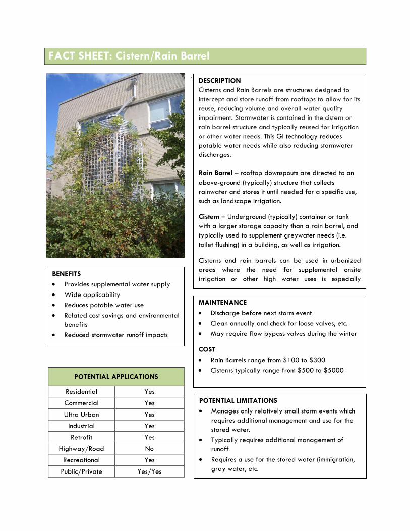
DESCRIPTION
Cisterns and Rain Barrels are structures designed to
intercept and store runoff from rooftops to allow for its
reuse, reducing volume and overall water quality
impairment. Stormwater is contained in the cistern or
rain barrel structure and typically reused for irrigation
or other water needs. This GI technology reduces
potable water needs while also reducing stormwater
discharges.
Rain Barrel – rooftop downspouts are directed to an
above-ground (typically) structure that collects
rainwater and stores it until needed for a specific use,
such as landscape irrigation.
Cistern – Underground (typically) container or tank
with a larger storage capacity than a rain barrel, and
typically used to supplement greywater needs (i.e.
toilet flushing) in a building, as well as irrigation.
Cisterns and rain barrels can be used in urbanized
areas where the need for supplemental onsite
irrigation or other high water uses is especially
apparent
BENEFITS
Provides supplemental water supply
Wide applicability
Reduces potable water use
Related cost savings and environmental
benefits
Reduced stormwater runoff impacts
MAINTENANCE
Discharge before next storm event
Clean annually and check for loose valves, etc.
May require flow bypass valves during the winter
COST
Rain Barrels range from $100 to $300
Cisterns typically range from $500 to $5000
POTENTIAL LIMITATIONS
Manages only relatively small storm events which
requires additional management and use for the
stored water.
Typically requires additional management of
runoff
Requires a use for the stored water (immigration,
gray water, etc.

STORMWATER QUANTITY FUNCTIONS
STORMWATER QUALITY FUNCTIONS
ADDITIONAL CONSIDERATIONS
Volume Low/Medium TSS Medium Capital Cost Low/Medium
Groundwater Recharge
Low TP Medium Maintenance Medium
Peak Rate Low TN Medium Winter Performance Medium
Erosion Reduction
Low Temperature Medium Fast Track Potential Medium/High
Flood Protection Low/Medium Aesthetics Low/Medium
VARIATIONS
Rain barrels
Cistems, both underground and above ground
Tanks
Storage beneath a surface using manufactured products
Various sizes, materials, shapes, etc.
KEY DESIGN FEATURES
Small storm events are captured with most structures
Provide overflow for large storms events
Discharge water before next storm event
Consider site topography, placing structure upgradient
of planting (if applicable) in order to eliminate pumping
needs
SITE FACTORS
Water table to bedrock depth – N/A (although must be
considered for subsurface systems)
Soils – N/A
Slope – N/A
Potential hotspots – yes with treatment
Maximum drainage area – N/A
Top-left and bottom-left photos:
Rain barrels in use in the City of Lancaster
(Source: LiveGREEN)
Bottom-right photo: Rain barrel
prototype example
FACT SHEET: Bioretention (Rain Gardens)
POTENTIAL APPLICATIONS
Residential Yes
Commercial Yes
Ultra Urban Limited
Industrial Yes
Retrofit Yes
Recreational Yes
Public/Private Yes
Residential Yes
BENEFITS
Volume control & GW recharge,
moderate peak rate control
Versatile w/ broad applicability
Enhance site aesthetics and habitat
Potential air quality & climate benefits
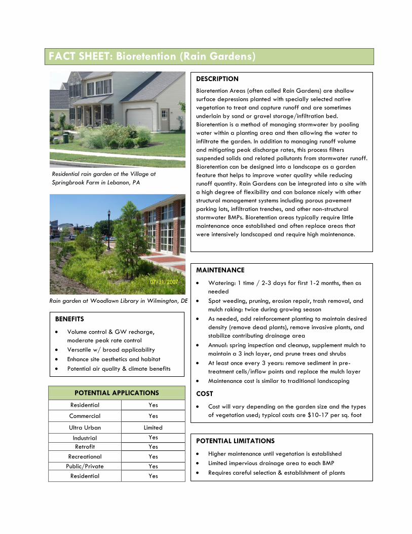
DESCRIPTION
Bioretention Areas (often called Rain Gardens) are shallow
surface depressions planted with specially selected native
vegetation to treat and capture runoff and are sometimes
underlain by sand or gravel storage/infiltration bed.
Bioretention is a method of managing stormwater by pooling
water within a planting area and then allowing the water to
infiltrate the garden. In addition to managing runoff volume
and mitigating peak discharge rates, this process filters
suspended solids and related pollutants from stormwater runoff.
Bioretention can be designed into a landscape as a garden
feature that helps to improve water quality while reducing
runoff quantity. Rain Gardens can be integrated into a site with
a high degree of flexibility and can balance nicely with other
structural management systems including porous pavement
parking lots, infiltration trenches, and other non-structural
stormwater BMPs. Bioretention areas typically require little
maintenance once established and often replace areas that
were intensively landscaped and require high maintenance.
Residential rain garden at the Village at
Springbrook Farm in Lebanon, PA
Rain garden at Woodlawn Library in Wilmington, DE
MAINTENANCE
Watering: 1 time / 2-3 days for first 1-2 months, then as
needed
Spot weeding, pruning, erosion repair, trash removal, and
mulch raking: twice during growing season
As needed, add reinforcement planting to maintain desired
density (remove dead plants), remove invasive plants, and
stabilize contributing drainage area
Annual: spring inspection and cleanup, supplement mulch to
maintain a 3 inch layer, and prune trees and shrubs
At least once every 3 years: remove sediment in pre-
treatment cells/inflow points and replace the mulch layer
Maintenance cost is similar to traditional landscaping
COST
Cost will vary depending on the garden size and the types
of vegetation used; typical costs are $10-17 per sq. foot
POTENTIAL LIMITATIONS
Higher maintenance until vegetation is established
Limited impervious drainage area to each BMP
Requires careful selection & establishment of plants

STORMWATER QUANTITY FUNCTIONS
STORMWATER QUALITY FUNCTIONS
ADDITIONAL CONSIDERATIONS
Volume Medium/High TSS High
(70-90%) Capital Cost Medium
Groundwater Recharge
Medium/High TP Medium (60%) Maintenance Medium
Peak Rate Medium TN Medium
(40-50%) Winter Performance Medium
Erosion Reduction Medium Temperature High Fast Track Potential Medium
Flood Protection Low/Medium Aesthetics High
VARIATIONS
Subsurface storage/infiltration bed
Use of underdrain
Use of impervious liner
KEY DESIGN FEATURES
Flexible in size and configuration
Ponding depths 6 to 18 inches for
drawdown within 48 hours
Plant selection (native vegetation that is
tolerant of hydrologic variability, salts, and
environmental stress)
Amend soil as needed
Provide positive overflow for extreme
storm events
Stable inflow/outflow conditions
SITE FACTORS
Water Table/ Bedrock Separation: 2-foot
minimum, 4-foot recommended
Soils: HSG A and B preferred; C & D may
require an underdrain
Feasibility on steeper slopes: medium
Potential Hotspots: yes with pretreatment
and/or impervious liner
Maximum drainage area: 5:1; not more
than 1 acre to one rain garden
Conceptual diagram showing process of bioretention
Linear bioretention area along roadway
Source: Low Impact Development Center, Inc.
Sou

FACT SHEET: Vegetated Roof
POTENTIAL APPLICATIONS
Residential Limited
Commercial Yes
Ultra Urban Yes
Industrial Yes
Retrofit Yes
Highway/Road No
Recreational Yes
Public/Private Yes/Yes
DESCRIPTION
A vegetated roof cover is a veneer of vegetation that is grown
on and covers an otherwise conventional flat or pitched roof,
endowing the roof (< 30 degree slope) with hydrologic
characteristics that more closely match surface vegetation than
the roof. The overall thickness of the veneer typically ranges
from 2 to 6 inches and may contain multiple layers, consisting
of waterproofing, synthetic insulation, nonsoil engineered
growth media, fabrics, and synthetic components. Vegetated
roofs, also called “green rooftops” can be optimized to
achieve water quantity and water quality benefits. Through
the appropriate selection of materials, even thin vegetated
covers can provide significant rainfall retention and detention
functions.
Depending on the plant material and planned usage for the
roof area, modern vegetated roofs can be categorized as
systems that are intensive, semi-intensive, or extensive.
Intensive vegetated roofs utilize a wide variety of plant
species that may include trees and shrubs, require deeper
substrate layers (usually > 4 inches), are generally limited to
flat roofs, require „intense‟ maintenance, and are often
park-like areas accessible to the general public. Extensive
vegetated roofs are limited to herbs, grasses, mosses, and
drought tolerant succulents such as sedum, can be sustained in a
shallow substrate layer (<4 inches), require minimal
maintenance once established, and are generally not designed
for access by the public. These vegetated roofs are typically
intended to achieve a specific environmental benefit, such as
rainfall runoff mitigation. Extensive roofs are well suited to
rooftops with little load bearing capacity and sites which are
not meant to be used as roof gardens. Semi-intensive
vegetated roofs fall between intensive and extensive
vegetated roof systems. More maintenance, higher costs and
more weight are the characteristics for this intermediate system
compared to that of the extensive vegetated roof.
BENEFITS
High volume reduction (annual basis)
Moderate ecological value and habitat
High aesthetic value
Energy benefits (heating/cooling)
Urban heat island reduction
MAINTENANCE
Once vegetation is established, little to no maintenance
needed for the extensive system
Maintenance cost is similar to traditional landscaping,
$0.25-$1.25 per square foot
COST
$5 - $50 per square foot, including all structural
components, soil, and plants; more expensive than
traditional roofs, but have longer lifespan; generally less
expensive to install on new roof versus retrofit on existing
roof
POTENTIAL LIMITATIONS
Higher maintenance needs until
vegetation is established
Need for adequate roof structure; can
be challenging on retrofit application
STORMWATER QUANTITY FUNCTIONS
STORMWATER QUALITY FUNCTIONS
ADDITIONAL CONSIDERATIONS
Volume Medium/High TSS Medium Capital Cost High
Groundwater Recharge
Low TP Medium Maintenance Medium
Peak Rate Medium TN Medium Winter Performance Medium
Erosion Reduction Low/Medium Temperature Medium Fast Track Potential Low
Flood Protection Low/Medium Aesthetics High
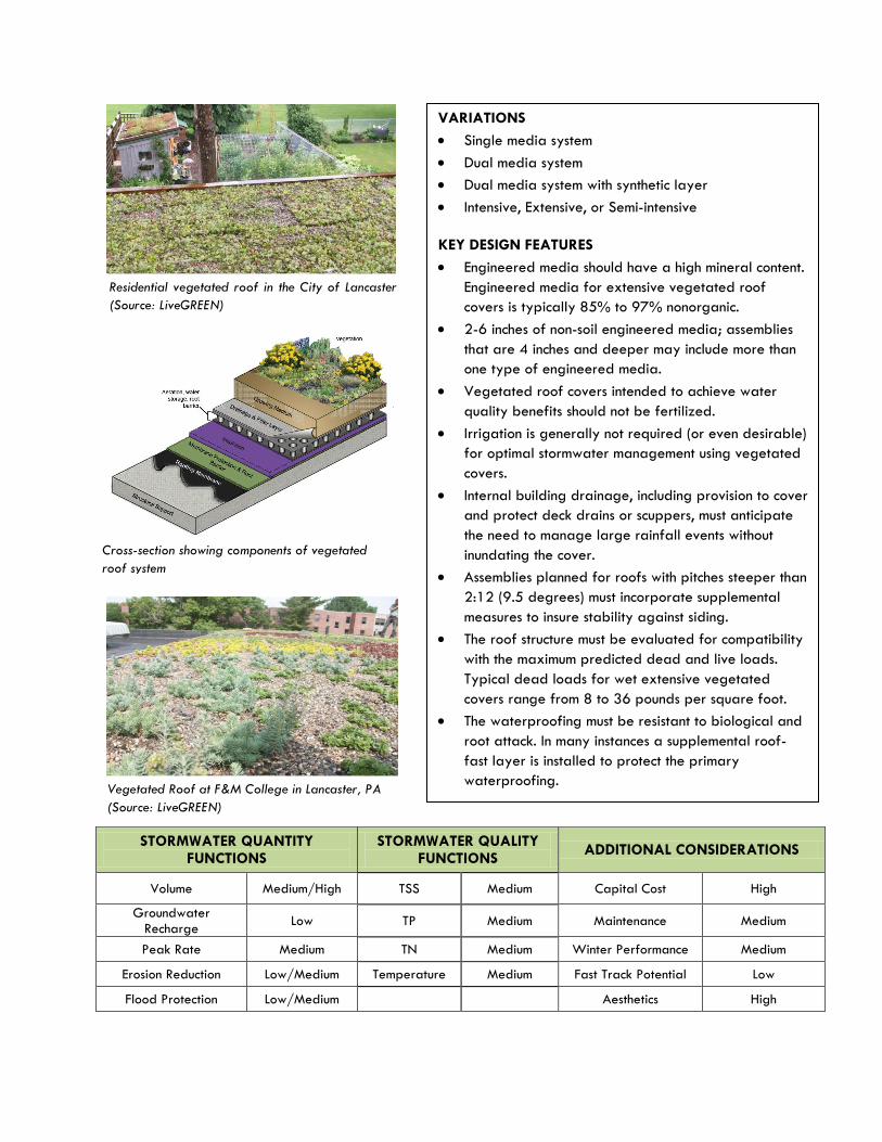
VARIATIONS
Single media system
Dual media system
Dual media system with synthetic layer
Intensive, Extensive, or Semi-intensive
KEY DESIGN FEATURES
Engineered media should have a high mineral content.
Engineered media for extensive vegetated roof
covers is typically 85% to 97% nonorganic.
2-6 inches of non-soil engineered media; assemblies
that are 4 inches and deeper may include more than
one type of engineered media.
Vegetated roof covers intended to achieve water
quality benefits should not be fertilized.
Irrigation is generally not required (or even desirable)
for optimal stormwater management using vegetated
covers.
Internal building drainage, including provision to cover
and protect deck drains or scuppers, must anticipate
the need to manage large rainfall events without
inundating the cover.
Assemblies planned for roofs with pitches steeper than
2:12 (9.5 degrees) must incorporate supplemental
measures to insure stability against siding.
The roof structure must be evaluated for compatibility
with the maximum predicted dead and live loads.
Typical dead loads for wet extensive vegetated
covers range from 8 to 36 pounds per square foot.
The waterproofing must be resistant to biological and
root attack. In many instances a supplemental roof-
fast layer is installed to protect the primary
waterproofing.
Residential vegetated roof in the City of Lancaster
(Source: LiveGREEN)
Vegetated Roof at F&M College in Lancaster, PA
(Source: LiveGREEN)
Cross-section showing components of vegetated
roof system

FACT SHEET: Stormwater Planter Box
POTENTIAL APPLICATIONS
Residential Yes
Commercial Yes
Ultra Urban Yes
Industrial Limited
Retrofit Yes
Highway/Road Limited
Recreational Limited
Private Yes
DESCRIPTION
A Planter Box is a container or enclosed feature
located either above ground or below ground,
planted with vegetation that captures
stormwater within the structure itself. Planter
Boxes can play an important role in urban areas
by minimizing stormwater runoff, reducing water
pollution, and creating a greener and healthier
appearance by retaining stormwater rather
than allowing it to directly drain into nearby
sewers. Planter Boxes receive runoff usually
from rooftop areas and must be located
reasonably close to downspouts or structures
generating runoff. Stormwater runoff is used to
irrigate the plants, and the vegetation in the
planter box reduces stormwater through
evapotranspiration.
Boxes can take any number of different
configurations and be made out of a variety of
different materials, although many are
constructed from wood or concrete.
Underground Planter Boxes designed to
infiltrate can be constructed alongside buildings
provided that proper waterproofing measures
are used to protect foundations.
Planter box in Lansing, Michigan
BENEFITS
Enhance site aesthetics and habitat
Potential air quality and climate benefits
Potential runoff and combined sewer overflow
reductions
Wide applicability including ultra-urban
areas
MAINTENANCE
See Rain Garden maintenance
Bypass valve during winter
Maintenance cost: $400-$500 per year for
a 500 square foot planter; varies based on
type, size, plant selection, etc.
COST
Varies based on type, size, plant selection,
etc., but is approx. $8-15 per square foot
POTENTIAL LIMITATIONS
Limited stormwater quantity/quality benefits
Relatively high cost due to structural
components for some variations

STORMWATER QUANTITY FUNCTIONS
STORMWATER QUALITY FUNCTIONS
ADDITIONAL CONSIDERATIONS
Volume Low/Medium TSS Medium Capital Cost Low/Medium
Groundwater Recharge
Low TP Medium Maintenance Medium
Peak Rate Low TN Medium Winter
Performance Medium
Erosion Reduction Low Temperature Medium Fast Track Potential Low
Flood Protection Low Aesthetics High
VARIATIONS
Contained (above ground)
Infiltration (below ground)
Flow-through
KEY DESIGN FEATURES
Native vegetation
May be designed as pretreatment
May be designed to infiltrate
Captured runoff to drain out in 3 to 4
hours after storm even unless used for
irrigation
Receive less than 15, 000 square feet of
impervious area runoff (typ.)
The structural elements of the planters
should be stone, concrete, brick, or
pressure-treated wood
Flow bypass during winter
SITE FACTORS
Water Table and Bedrock Depth – N/A
for contained and flow-through, 2 feet
minimum for Infiltration Planter Box
Soils – N/A for contained and flow-
through, HSG A&B preferred for
Infiltration
Potential Hotspots – yes for contained
and flow-through; no for infiltration
Infiltration planter box at Woodlawn Library, Wilmington, DE
Conceptual diagram showing infiltration
FACT SHEET: Infiltration Practices
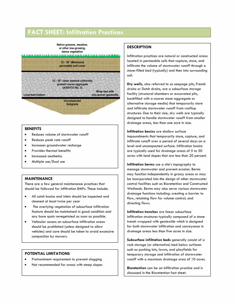
DESCRIPTION
Infiltration practices are natural or constructed areas
located in permeable soils that capture, store, and
infiltrate the volume of stormwater runoff through a
stone-filled bed (typically) and then into surrounding
soil.
Dry wells, also referred to as seepage pits, French
drains or Dutch drains, are a subsurface storage
facility (structural chambers or excavated pits,
backfilled with a coarse stone aggregate or
alternative storage media) that temporarily store
and infiltrate stormwater runoff from rooftop
structures. Due to their size, dry wells are typically
designed to handle stormwater runoff from smaller
drainage areas, less than one acre in size.
Infiltration basins are shallow surface
impoundments that temporarily store, capture, and
infiltrate runoff over a period of several days on a
level and uncompacted surface. Infiltration basins
are typically used for drainage areas of 5 to 50
acres with land slopes that are less than 20 percent.
Infiltration berms use a site’s topography to
manage stormwater and prevent erosion. Berms
may function independently in grassy areas or may
be incorporated into the design of other stormwater
control facilities such as Bioretention and Constructed
Wetlands. Berms may also serve various stormwater
drainage functions including: creating a barrier to
flow, retaining flow for volume control, and
directing flows.
Infiltration trenches are linear subsurface
infiltration structures typically composed of a stone
trench wrapped with geotextile which is designed
for both stormwater infiltration and conveyance in
drainage areas less than five acres in size.
Subsurface infiltration beds generally consist of a
rock storage (or alternative) bed below surfaces
such as parking lots, lawns, and playfields for
temporary storage and infiltration of stormwater
runoff with a maximum drainage area of 10 acres.
Bioretention can be an infiltration practice and is
discussed in the Bioretention fact sheet.
MAINTENANCE
There are a few general maintenance practices that
should be followed for infiltration BMPs. These include:
All catch basins and inlets should be inspected and
cleaned at least twice per year
The overlying vegetation of subsurface infiltration
feature should be maintained in good condition and
any bare spots revegetated as soon as possible.
Vehicular access on subsurface infiltration areas
should be prohibited (unless designed to allow
vehicles) and care should be taken to avoid excessive
compaction by mowers.
BENEFITS
Reduces volume of stormwater runoff
Reduces peak rate runoff
Increases groundwater recharge
Provides thermal benefits
Increased aesthetics
Multiple use/Dual use
POTENTIAL LIMITATIONS
Pretreatment requirement to prevent clogging
Not recommended for areas with steep slopes

Potential Applications
Residential Commercial Ultra Urban
Industrial Retrofit Highway/
Road Recreati-
onal Private
Dry Well Yes Yes Yes Limited Yes No Yes Yes
Infiltration Basin
Yes Yes Limited Yes Yes Limited Yes Yes
Infiltration Berm
Yes Yes Limited Yes Yes Yes Yes Yes
Infiltration Trench
Yes Yes Yes Yes Yes Yes Yes Yes
Subsurface Infiltration
Bed Yes Yes Yes Yes Yes Limited Yes Yes
VARIATIONS
Rain barrels
Cistems, both underground and above ground
Tanks
Storage beneath a surface using manufactured
products
Various sizes, materials, shapes, etc.
KEY DESIGN FEATURES
Depth to water table or bedrock
Pretreatment is often needed to prevent clogging
Often required level infiltration surface
Proximity to buildings, drinking water supplies,
karst features, and other sensitive areas
Soil types (permeability, limiting layer, etc.)
Provide positive overflow in most uses
SITE FACTORS
Maximum Site Slope: 20 percent
Minimum depth to bedrock: 2 feet
Minimum depth to seasonally high water table: 2
feet
Potential Hotspots: yes with pretreatment and/or
impervious liner
HSG Soil type: A and B preferred,
C & D may require an underdrain
Maximum drainage area – N/A
COST
Dry Well: Construction costs –
$4-9/ft3, Maintenance Costs –
5-10% of capital costs
Infiltration basin: Construction costs –
varies depending on excavation,
plantings, and pipe configuration
Infiltration Trench: Construction costs –
$20-30/ft3, Maintenance Costs – 5-
10% of capital costs
Subsurface Infiltration Bed:
Construction costs – 13/ft3
Subsurface Infiltration Bed using Rainstore ™ blocks for storage media, Washington National Cathedral,
DC

Stormwater Quantity Functions
Volume Groundwater
Recharge Peak Rate
Erosion Reduction
Flood Protection
Dry Well Medium High Medium Medium Low
Infiltration Basin High High High Medium High
Infiltration Berm Low/Medium Low/Medium Medium Medium/High Medium
Infiltration Trench Medium High Low/Medium Medium/High Low/Medium
Subsurface Infiltration Bed
High High High Medium/High Medium/High
Stormwater Quality Functions
TSS TP TN Temperature Dry Well Medium (85%) High/Medium (85%) Medium/Low (30%) High
Infiltration Basin High (85%) Medium/High (85%) Medium (30%) High
Infiltration Berm Medium/High (60%) Medium (50%) Medium (40%) Medium
Infiltration Trench Medium (85%) High/Medium (85%) Medium/Low (30%) High
Subsurface Infiltration Bed High (85%) Medium/High (85%) Low (30%) High
Capital Cost Medium
Life Cycle Costs Medium
Maintenance Medium
Winter Performance High
Resistance to Heat High
Fast Track Potential Medium
Aesthetics Medium
Level Spreader for
Even Distribution
The Vegetated Infiltration Basin beneath this
playfield manages rooftop runoff from the adjacent
school building, Philadelphia, PA
Additional Considerations
Gently Sloping Sides
Vegetated Infiltration Basin outside of Allentown, PA
Infiltration trench Chester County, PA

FACT SHEET: Pervious Pavement with Infiltration
POTENTIAL APPLICATIONS
Residential Yes
Commercial Yes
Ultra Urban Yes
Industrial Yes
Retrofit Yes
Highway Limited
Recreational Yes
Public Yes
DESCRIPTION
Pervious pavement is a Green Infrastructure (GI)
technique that combines stormwater infiltration,
storage, and structural pavement consisting of a
permeable surface underlain by a storage/infiltration
bed. Pervious pavement is well suited for parking lots,
walking paths, sidewalks, playgrounds, plazas, tennis
courts, and other similar uses.
A pervious pavement system consists of a pervious
surface course underlain by a storage bed placed on
uncompacted subgrade to facilitate stormwater
infiltration. The storage reservoir may consist of a
stone bed of uniformly graded, clean and washed
course aggregate with a void space of approximately
40% or other pre-manufactured structural storage
units. The pervious pavement may consist of asphalt,
concrete, permeable paver blocks, reinforced
turf/gravel, or other emerging types of pavement.
BENEFITS
Volume control & GW recharge, moderate peak
rate control
Versatile with broad applicability
Dual use for pavement structure and stormwater
management
MAINTENANCE
Clean inlets
Vacuum annually
Maintain adjacent landscaping/planting beds
Periodic replacement of paver blocks
Maintenance cost: approximately $400-500 per
year for vacuum sweeping of a half acre parking
lot
COST
Varies by porous pavement type
Local quarry needed for stone filled infiltration
bed
$7-$15 per square foot, including underground
infiltration bed
Generally more than standard pavement, but
saves on cost of other BMPs and traditional
drainage infrastructure
Porous pavers on the right,
standard asphalt on the left, in
San Diego, CA
Porous concrete sidewalk
at State College, PA
POTENTIAL LIMITATIONS
Careful design & construction required
Pervious pavement not suitable for all uses
Higher maintenance needs than standard
pavement
Steep slopes

STORMWATER QUANTITY FUNCTIONS
STORMWATER QUALITY FUNCTIONS
ADDITIONAL CONSIDERATIONS
Volume High TSS High Capital Cost Medium
Groundwater Recharge
High TP Medium Maintenance Medium
Peak Rate Medium/High TN High Winter
Performance Medium/High
Erosion Reduction Medium/High Temperature High Fast Track Potential Low/Medium
Flood Protection Medium/High Aesthetics Low/Medium
KEY DESIGN FEATURES
Infiltration testing required
Do not infiltrate on compacted soil
Level storage bed bottoms
Provide positive storm water overflow
from bed
Surface permeability >20”/hr
Secondary inflow mechanism
recommended
Pretreatment for sediment-laden runoff
SITE FACTORS
Water Table/Bedrock Separation: 2-foot
minimum
Soils: HSG A&B preferred; HSG C&D
may require underdrains
Feasibility on steeper slopes: Low
Potential Hotspots: Not without design of
pretreatment system/impervious liner
Conceptual diagram showing how porous pavement functions
Porous asphalt path at Gray Towers Natl. Historic Site, PA Porous asphalt parking lot in Wilm., DE
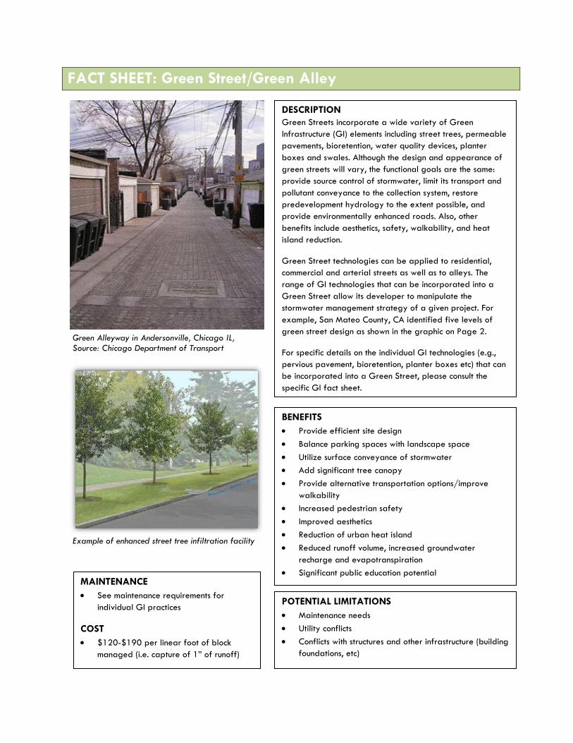
FACT SHEET: Green Street/Green Alley
DESCRIPTION
Green Streets incorporate a wide variety of Green
Infrastructure (GI) elements including street trees, permeable
pavements, bioretention, water quality devices, planter
boxes and swales. Although the design and appearance of
green streets will vary, the functional goals are the same:
provide source control of stormwater, limit its transport and
pollutant conveyance to the collection system, restore
predevelopment hydrology to the extent possible, and
provide environmentally enhanced roads. Also, other
benefits include aesthetics, safety, walkability, and heat
island reduction.
Green Street technologies can be applied to residential,
commercial and arterial streets as well as to alleys. The
range of GI technologies that can be incorporated into a
Green Street allow its developer to manipulate the
stormwater management strategy of a given project. For
example, San Mateo County, CA identified five levels of
green street design as shown in the graphic on Page 2.
For specific details on the individual GI technologies (e.g.,
pervious pavement, bioretention, planter boxes etc) that can
be incorporated into a Green Street, please consult the
specific GI fact sheet.
MAINTENANCE
See maintenance requirements for
individual GI practices
COST
$120-$190 per linear foot of block
managed (i.e. capture of 1” of runoff)
BENEFITS
Provide efficient site design
Balance parking spaces with landscape space
Utilize surface conveyance of stormwater
Add significant tree canopy
Provide alternative transportation options/improve
walkability
Increased pedestrian safety
Improved aesthetics
Reduction of urban heat island
Reduced runoff volume, increased groundwater
recharge and evapotranspiration
Significant public education potential
Enhanced tree health/longevity
Green Alleyway in Andersonville, Chicago IL, Source: Chicago Department of Transport
POTENTIAL LIMITATIONS
Maintenance needs
Utility conflicts
Conflicts with structures and other infrastructure (building
foundations, etc)
Example of enhanced street tree infiltration facility

POTENTIAL APPLICATIONS
Residential Yes Retrofit Yes
Commercial Yes Highway/Road Yes
Ultra Urban Yes Recreational Yes
Industrial Yes Public/Private Yes
STORMWATER QUANTITY FUNCTIONS
STORMWATER QUALITY FUNCTIONS
ADDITIONAL CONSIDERATIONS
Volume Medium TSS High (70-90%) Capital Cost Medium
Groundwater Recharge
Medium TP Medium (60%) Maintenance Medium/High
Peak Rate Medium TN Medium (40-
50%) Winter
Performance High
Erosion Reduction Medium Temperature High Fast Track Potential
Low/Medium
Flood Protection Low/Medium Aesthetics High
VARIATIONS
Porous pavement (street
and/or sidewalk)
Vegetated curb extensions
Infiltration planters
Infiltration trenches
Enhanced tree plantings
Water quality inlets
KEY DESIGN FEATURES
See individual GI fact
sheets: Tree Trench,
Vegetated Curb Extension,
Porous Pavement, etc.
SITE FACTORS
Slope
Soils
Utilities
Size of right-of-way
See site factors for
individual
GI practices
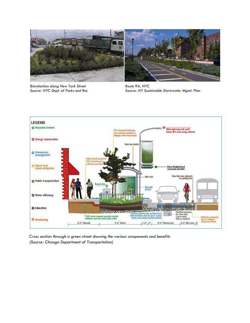
Cross section through a green street showing the various components and benefits
(Source: Chicago Department of Transportation)
Bioretention along New York Street Route 9A, NYC Source: NYC Dept. of Parks and Rec Source: NY Sustainable Stormwater Mgmt. Plan

FACT SHEET: Vegetated Swale
POTENTIAL APPLICATIONS
Residential Yes
Commercial Yes
Ultra Urban Limited
Industrial Yes
Retrofit Limited
Highway/Road Yes
Recreational Yes
Public/Private Yes
DESCRIPTION
A vegetated swale, also called a drainage swale or bioswale,
is a shallow stormwater channel that is densely planted with a
variety of grasses, shrubs, and/or trees designed to slow,
filter, and infiltrate stormwater runoff. Vegetated swales are
an excellent alternative to conventional curb and gutter
conveyance systems, because they provide pretreatment and
can distribute stormwater flows to subsequent BMPs.
Vegetated swales are sometimes used as pretreatment devices
for other structural BMPs, especially from roadway runoff.
While swales themselves are intended to effectively treat
runoff from highly impervious surfaces, pretreatment measures
are recommended to enhance swale performance. Check dams
can be used to improve performance and maximize infiltration,
especially in steeper areas. Check dams made of wood, stone,
or concrete are often employed to enhance infiltration
capacity, decrease runoff volume, rate, and velocity. They also
promote additional filtering and settling of nutrients and other
pollutants. Check-dams create a series of small, temporary
pools along the length of the swale, which drain down within a
maximum of 48 hours.
BENEFITS
Can replace curb and gutter for site
drainage and provide significant cost
savings
Water quality enhancement (i.e. filtration)
Peak and volume control with infiltration
Can fit into the layout, topography, and landscaping plans of a particular project
with relative ease
MAINTENANCE
Remulch void areas, treat or replace diseased trees and
shrubs, and keep overflow free and clear of leaves as
needed
Inspect soil and repair eroded areas, remove litter and
debris, and clear leaves and debris from overflow
Inspect trees and shrubs to evaluate health
Add additional mulch, inspect for sediment buildup, erosion, vegetative conditions, etc. annually
Maintenance cost: approximately $200 per year for a 900 square foot vegetated swale
COST
$5-20 per linear foot depending on extent of grading
and infrastructure required, as well as the vegetation used
Vegetated swales at Swarthmore College
(Swarthmore, PA)
POTENTIAL LIMITATIONS
Limited application in areas where space is a concern
Unless designed for infiltration, there is limited peak and
volume control

STORMWATER QUANTITY FUNCTIONS
STORMWATER QUALITY FUNCTIONS
ADDITIONAL CONSIDERATIONS
Volume Low/Medium TSS Medium/High
(50%) Capital Cost Low/Medium
Groundwater Recharge
Low/Medium TP Low/High
(50%) Maintenance Low/Medium
Peak Rate Low/Medium TN Medium (20%)
Winter Performance
Medium
Erosion Reduction Medium Temperature Medium/High Fast Track Potential High
Flood Protection Low Aesthetics Medium
VARIATIONS
Vegetated swale with infiltration
trench
Linear wetland swale
Grass swale
Check-dams
KEY DESIGN FEATURES
Handles the 10-year storm event with
some freeboard
Two-year storm flows do not cause
erosion
Maximum contributing drainage area
is 5 acres
Bottom width of 2-8 feet
Side slopes from 3:1 (H:V) to 5:1
Longitudinal slope from 1% to 6%
Check dams can provide additional storage and infiltration
SITE FACTORS
Water table to bedrock depth – 2
foot minimum
Soils – A&B preferred, C&D may
require an underdrain
Potential hotspots – No
Curb opening to grass swale in residential development

FACT SHEET: Tree Trench
POTENTIAL APPLICATIONS
Residential Yes
Commercial Yes
Ultra Urban Limited
Industrial Yes
Retrofit Yes
Highway/Road Yes
Recreational Yes
Public/Private Yes
DESCRIPTION
Tree trenches perform the same functions
that other infiltration practices perform
(infiltration, storage, evapotranspiration
etc.) but in addition provide an increased
tree canopy.
BENEFITS
Increased canopy cover
Enhanced site aesthetics
Air quality and climate benefits
Runoff reductions
Water quality benefits
High fast track potential
Enhanced tree health/longevity
MAINTENANCE
Water, mulch, treat diseased trees, and
remove litter as needed
Annual inspection for erosion, sediment
buildup, vegetative conditions
Biannual inspection of cleanouts, inlets,
outlets, etc.
Maintenance cost for prefabricated
tree pit: $100-$500 per year
COST
$850 per tree
$ 10-$15 per square foot
$8000-$10,000 to purchase one
prefabricated tree pit system including
filter material, plants, and some
maintenance; $1500-$6000 for
installation
POTENTIAL LIMITATIONS
Required careful selection of tree
species
Required appropriate root zone area
Utility conflicts, including overhead
electric wires, posts,
signs, etc.
Conflicts with other structures
(basements, foundations, etc.)
Tree trench in urban setting (Viridian Landscape
Studio)

STORMWATER QUANTITY FUNCTIONS
STORMWATER QUALITY FUNCTIONS
ADDITIONAL CONSIDERATIONS
Volume Medium TSS High (70-90%) Capital Cost Medium
Groundwater Recharge
Medium TP Medium (60%) Maintenance Medium
Peak Rate Medium TN Medium (40-
50%) Winter
Performance High
Erosion Reduction Medium Temperature High Fast Track Potential High
Flood Protection Low/Medium Aesthetics High
VARIATIONS
Structural soil or alternative (eg. Silva Cell)
Porous pavers
Open vegetated tree trench strip (planted
with ground cover or grass)
Tree grates
Alternate storage media (modular storage
units)
Prefabricated tree pit
KEY DESIGN FEATURES
Flexible in size and infiltration
Native Plants
Quick drawdown
Linear infiltration/storage trench
Adequate tree species selection and
spacing
New inlets, curb cuts, or other means to
introduce runoff into the trench
SITE FACTORS
Overhead clearance; minimize utility
conflict
Root zone
Water table
Soil permeability/Limiting zones
TOP LEFT: Tree trench with porous pavers and subsurface infiltration bed, located in City Lot No. 21, Syracuse, NY LEFT: Tree trench located at Upper Darby Park outside of Philadelphia, PA

Example of Tree Trench adjacent to a Subsurface Infiltration Bed
Example of Street Tree Trench with Structural Soil and Adjacent Infiltration Trench – Cross-Section A
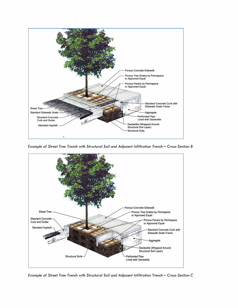
Example of Street Tree Trench with Structural Soil and Adjacent Infiltration Trench – Cross-Section B
Example of Street Tree Trench with Structural Soil and Adjacent Infiltration Trench – Cross-Section C

FACT SHEET: Vegetated Curb Extension
POTENTIAL APPLICATIONS
Residential Yes
Commercial Yes
Ultra Urban Yes
Industrial Yes
Retrofit Yes
Highway/Road Limited
Recreational Yes
Private Yes
DESCRIPTION
Vegetated curb extensions, also called
stormwater curb extensions, are landscaped
areas within the parking zone of a street that
capture stormwater runoff in a depressed
planting bed. The landscaped area can be
designed similar to a rain garden or vegetated
swale, utilizing infiltration and
evapotranspiration for stormwater management.
They can be planted with groundcover, grasses,
shrubs or trees, depending on the site conditions,
costs, and design context.
Vegetated curb extensions can be used at a
roadway intersection, midblock, or along the
length or block of the roadway, and can be
combined with pedestrian crosswalks to increase
safety along a roadway. Additionally,
vegetated curb extensions provide traffic
calming opportunities along with stormwater
management opportunities. Vegetated curb
extensions can be added to existing roadways
with minimal disturbance and are very cost
effective as retrofit opportunities. They can be
used in a variety of land uses, and are a good
technique to incorporate along steeply sloping
roadways. They are also effective pretreatment
(i.e. filtration) practices for runoff entering other
Green Street practices, such as infiltration
trenches.
BENEFITS
Traffic calming and pedestrian safety
Enhanced site aesthetics, habitat
Potential air quality and climate benefits
Potential combined sewer overflow
reductions
Wide applicability, including in ultra-urban
areas
Reduced runoff, improved water quality
Works well with existing infrastructure
MAINTENANCE
Remove accumulated debris
Clean inlets
COST
Relatively inexpensive to retrofit
$ 30/square foot for new construction
POTENTIAL LIMITATIONS
Could require removal of on-street parking
Conflict with bike lane
Utility and fire hydrant conflicts
Urban application of a vegetated curb extension in
Portland, Oregon (Source: www.artfulstormwater.net)

STORMWATER QUANTITY FUNCTIONS
STORMWATER QUALITY FUNCTIONS
ADDITIONAL CONSIDERATIONS
Volume Medium TSS Medium/High Capital Cost Low
Groundwater Recharge
Medium TP Medium Maintenance Low/Medium
Peak Rate Medium TN Medium Winter
Performance Medium
Erosion Reduction
Medium Temperature Medium/High Fast Track Potential
Low/Medium
Flood Protection Low/Medium Aesthetics High
VARIATIONS
Bulb-out; Bump-out
Stormwater Curb Extension
KEY DESIGN FEATURES
Design can incorporate existing inlets
Size to handle runoff from the
catchment area
Infiltration testing required
Do not infiltrate on compacted soil
Level storage bed bottoms
Native vegetation
Work around existing utilities
Mark curb cuts highly visible to
motorists
SITE FACTORS
Water Table/Bedrock Separation; 2-
foot minimum.
Soils: HSG A&B preferred; HSG C&D
may require underdrains
Feasibility on steeper slopes: high.
Design to include backstop or check
dam
Vegetated curb extensions in Berwyn, PA
Source: CH2M HILL
Residential application of a vegetated curb extension in
Portland, Oregon (Source: www.artfulstormwater.net)