Embed Size (px)
Citation preview

APPENDIX 2E
Mechanical Engineering Design Criteria

Vacaville Energy Center 3.3 - 1 VEC AFC 071508 Rev. A
3.0 MECHANICAL DESIGN CRITERIA This section describes the primary mechanical equipment and systems, their functions, and the criteria upon which their design will be based for the Vacaville Energy Center. Codes and Standards The design of the mechanical systems and components will be in accordance with the laws and regulations of the federal government, state of California, Solano County ordinances, and industry standards. The current issue or revision of the documents at the time of the filing of this Application for Certification (AFC) will apply, unless otherwise noted. If there are conflicts between the cited documents, the more conservative requirements shall apply. The following codes and standards are applicable to the mechanical aspects of the power facility. • California Building Standards Code, 2001 • American Society of Mechanical Engineers (ASME) Boiler and Pressure Vessel Code • ASME/ANSI B31.1 Power Piping Code • ASME Performance Test Codes • ASME Standard TDP-1 • American National Standards Institute (ANSI) B16.5, B16.34, and B133.8 • American Boiler Manufacturers Association (ABMA) • American Gear Manufacturers Association (AGMA) • Air Moving and Conditioning Association (AMCA) • American Society for Testing and Materials (ASTM) • American Society of Heating, Refrigerating, and Air Conditioning Engineers (ASHRAE) • American Welding Society (AWS) • Cooling Tower Institute (CTI) • Heat Exchange Institute (HEI) • Manufacturing Standardization Society (MSS) of the Valve and Fitting Industry • National Fire Protection Association (NFPA) • Hydraulic Institute Standards (HIS) • Tubular Exchanger Manufacturer’s Association (TEMA)
3.1 Combustion Turbine Generator (CTG)
Each CTG will be supplied with a metal acoustical enclosure suitable for outdoor installation. The CTG’s will use Dry Low NOx combustors to control exhaust gas NOx. The CTG’s will also have evaporative coolers installed for performance enhancement capabilities. Each CTG generator will be a totally enclosed water to air cooled (TEWAC) or hydrogen cooled direct-drive, 2-pole, 60 Hz synchronous machine.

Vacaville Energy Center 3.3 - 2 VEC AFC 071508 Rev. A
Mechanical auxiliary systems for the CTG, which are to be supplied as part of the CTG supplier scope, will be as follows:
• Lubricating and hydraulic oil system • Oil-to-Water lube oil coolers • Fuel gas system, including fuel gas metering valve • Inlet air filtration (static filters) system • Fire protection and detection system for the CTG • Turbine compartment vent fans • Generator compartment vent fans • Lube oil filtration system • Online/offline water wash system
CTG inlet air conditioning will be accomplished via an evaporative cooling system. The inlet cooling system will be provided by the OEM. The inlet cooling system will be designed to achieve a compressor inlet temperature that is within 2 deg F of the wet bulb temperature. The inlet cooling system will be complete with pumps, nozzles, interconnecting piping, valves, controls, and other equipment necessary to function across typical load and ambient range. Equipment will be designed for outdoor installation in ambient conditions.
3.2 Steam Turbine Generator (STG)
The STG will be supplied with a metal acoustical enclosure suitable for outdoor installation. The generator will be a totally enclosed water to air cooled (TEWAC) or hydrogen cooled direct-drive, 2-pole, 60 Hz synchronous machine. Mechanical auxiliary systems for the STG, which are to be supplied as part of the STG supplier scope, will be as follows:
• Lubricating and hydraulic oil system • Oil-to-Water lube oil coolers • Fire protection and detection system for the STG • Starter System (Starting Motor and fluid drive for STG) • Turbine compartment vent fans • Generator compartment vent fans • Lube oil filtration system
Equipment will be designed for outdoor installation.

Vacaville Energy Center 3.3 - 3 VEC AFC 071508 Rev. A
3.3 Heat Recovery Steam Generators (HRSG’s)
3.3.1 HRSG Description The HRSGs will be duct fired, three-pressure, reheat, natural circulation, drum type with horizontal gas flow, complete with manual main steam isolation valves, feedwater stop and check valves, relief valves, and a continuous and intermittent blowdown system. The high pressure (HP), intermediate pressure (IP), and low pressure LP sections will each consist of an economizer, evaporator, and superheater section. The reheat section will heat IP steam and exhaust steam from the HP section of the steam turbine for admission into the IP/LP turbine. The HRSGs will be designed and constructed to operate within the maximum exhaust gas flow and temperature ranges of the CTGs. The HRSGs will be designed for outdoor installation, with full enclosures over the drum areas. The HRSG will be fabricated, assembled, inspected and tested in accordance with Section 1 (Power Boilers) of the ASME Boiler and Pressure Vessel Code. The HRSG external piping will be furnished, installed and tested in accordance with the requirements of ASME B31.1 (Power Piping) and Section 1 of the ASME, Boiler and Pressure Vessel Code. The HRSG drums and internals will be sized for required steam separation at the predicted HRSG performance conditions for the minimum HRSG drum pressure. In addition, the steam drums will be designed to accommodate surges associated with startup, shutdown and rapid load changes. Blowdown from each HRSG will be piped to its respective blowdown tank. Quench water to cool blowdown before discharge will be supplied from the raw water system. Rate of quench water flow will be automatically adjusted in accordance with blowdown temperature. The boiler blowdown tank will be located in the boiler blowdown sump. All topside drains will be routed to grade. The bottom drains will terminate on the side of the HRSG and the valves will be accessible at grade. The drains will be headered together and the header drained into the boiler blowdown sump. Quench water will be provided to the sump from the raw water system. The nitrogen purge connections, one per drum, will terminate at the valve located within three feet of grade. In the event that long-term lay-up is required, plant operations will have to provide a nitrogen trailer with the required connectors, hoses and regulators. The HRSG reheater section will be designed for “wet” operation during startup and in case of a steam turbine trip. Each HRSG scope of supply will include an A36 structural carbon steel stack with motorized stack dampers. The internal bottom portion of the breeching and stack (field welds and up ten (10) feet) will be coated and insulated with a “stalastic-type” material

Vacaville Energy Center 3.3 - 4 VEC AFC 071508 Rev. A
(such as Intertherm 228). Externally, the HRSG shall be insulated from the last tube row through the breeching up to the stack damper elevation. In addition, each HRSG scope of supply will include the necessary emissions control equipment (i.e., SCRs and/or CO catalysts) as specified in Section 1. The gas path will be insulated with ceramic fiber blanket to provide a skin temperature of not more than 140°F, and lined with stainless steel (ASTM A-312 grade 309 where temperatures exceed 800°F). Man-ways will be provided for access to each section of the HRSG between modules. The manways will be provided with a davit, or will be hinged. The size of the opening will be suitable for maintenance expected in that section, and in no case be less than 24 X 18 inches. Operating areas of the HRSG will be provided with platforms. Exterior platforms, ladders, rails, and structural steel will be hot dip galvanized. Handrails will be fabricated from 1 ½ - inch diameter steel pipe. Penetrations through platform decking 6 inches or greater in diameter will be finished with plate material. The vent valves, safety relief valves, silencers, and supporting steel frames will be provided by the HRSG supplier. All vent lines will be extended to a safe location (pointing away from any platforms). Heat tracing and adequate draining of the HRSG in cold weather will be used to prevent freeze-up of the internal pping of the HRSG. Drain lines will be provided after the double block valves, as well as impulse lines from root valves up to and including transmitter blow-offs, and HP, IP, and LP Drum Level control valves. Drain line connections will also be provided on the vent side of the startup vent valve, power relief valve and safety valves. If silencers are provided with drains, the drain will be piped to a drain manifold. Each HRSG will be provided with sparging steam connections on all three drums at the lower downcomer connection, and additionally, a drum warming connection on the HP drum saturated steam lines. 3.3.2 Stack The stack will be provided with emission sampling ports in accordance with EPA, State, and local regulatory requirements. A platform located at the sampling port elevation will be provided with ladder access, either from grade or from an adjacent HRSG platform. An expanded metal standoff shield will be provided by HRSG supplier to prevent human contact with 140°F or hotter surfaces, unless external insulation is being utilized with a stack damper as described in 3.2.1 above. A davit will be provided by the HRSG supplier. An electric hoist and weatherproof 120 and 208-volt single-phase electrical outlets for powering tools and test equipment at the source test platform are to

Vacaville Energy Center 3.3 - 5 VEC AFC 071508 Rev. A
be provided. Aircraft warning lights will not be provided, in accordance with the FAA or the authority that has jurisdiction in the location of the site. Lightning protection will not be required. 3.3.3 Selective Catalytic Reduction System SCR system will be provided with catalyst modules designed to facilitate eventual replacement. The system will include a monorail and a hoist for loading & removing SCR catalyst blocks. Engineer will ascertain local process safety and site permitting requirements. The HRSG scope of supply will include (per unit):
1 Each Ammonia Injection Skid 1 Each Ammonia Dilution Vessel 1 Each Injection Grid 1 Lot SCR Catalyst 2 Each Blowers
One ammonia storage tank will be provided of sufficient size to allow unloading at least one full truckload of ammonia, and to provide at least 15 days of supply for normal 1x1 fuel gas operation. The system will also include ammonia piping to the ammonia injection skid. HRSG local instrumentation will be provided by HRSG supplier. All transmitters & measurement elements, including flow measurement devices will be furnished and located at a reasonable distance from the measured location.
3.4 Fire Protection System 3.4.1 General NFPA 850 and the applicable fire code will provide the general guidance for the fire protection considerations of the facility. A Fire Mitigation Design Plan will be prepared to detail the site-specific fire protection features of the facility. The fire prevention and protection design for the facility will be reviewed and must receive approval from the local Fire Marshal and Owner’s insurance representative. Automatic and manual fire protection systems employing detection and extinguishing equipment will be provided at all locations having potential fire hazard due to the presence of combustible materials or where major property damage could result. Yard

Vacaville Energy Center 3.3 - 6 VEC AFC 071508 Rev. A
hydrants and portable extinguishers will provide additional incipient fire extinguishing capability and overall protection throughout the plant site. The fire protection water supply will be taken from an onsite fire/raw water storage tank and distributed to the site fire protection system via a new underground firewater loop with necessary hydrants. The fire loop will be pressurized by an electric motor driven fire pump with a diesel driven fire pump as a backup. Hose houses will not be installed around the yard since plant-operating personnel will only be trained to extinguish incipient fires and local fire department personnel will only use their own hose.
3.4.2 Fire Protection System As a minimum, the fire protection system will include: Area of Building Standard Detail
Fire Extinguishers Site Wide NFPA 10
Use Dry Chemical only if it is best option Wheeled 33 gallon AFFF and 50 pound dry chemical extinguishers in the fuel oil pump, storage, and heating areas.
Fire Hose & Standpipe NFPA 14 Provide for the Warehouse
Fire Water Supply / Distribution Tank Fire Pumps/Controllers Underground piping/loop
NFPA 22 NFPA 20 NFPA 24
A tank level monitor will be provided at ground level. An approved flow meter and piping to the firewater tank will be provided to test each fire pump. Emergency fire department water supply connections should be provided by installing a suction connection at the tank, and a fire hose pumper connection downstream of the fire pump discharge valves. Sectional control valves should be provided so that no more than five hydrants or individual suppression systems would be out of service in the event of a main break.
Fire Hydrants NFPA 24 Hydrants will be spaced <=300 ft apart
Vacaville Energy Center 3.3 - 7 VEC AFC 071508 Rev. A
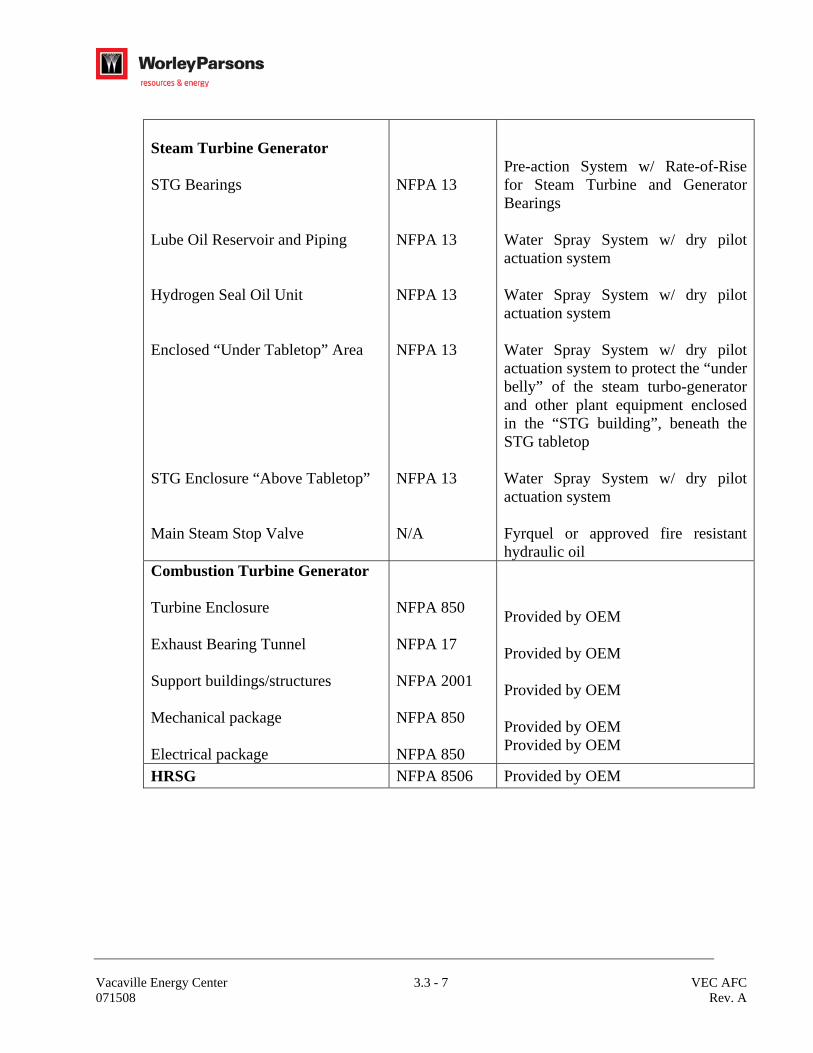
Steam Turbine Generator STG Bearings Lube Oil Reservoir and Piping Hydrogen Seal Oil Unit Enclosed “Under Tabletop” Area STG Enclosure “Above Tabletop” Main Steam Stop Valve
NFPA 13 NFPA 13 NFPA 13 NFPA 13 NFPA 13 N/A
Pre-action System w/ Rate-of-Rise for Steam Turbine and Generator Bearings Water Spray System w/ dry pilot actuation system Water Spray System w/ dry pilot actuation system Water Spray System w/ dry pilot actuation system to protect the “under belly” of the steam turbo-generator and other plant equipment enclosed in the “STG building”, beneath the STG tabletop Water Spray System w/ dry pilot actuation system Fyrquel or approved fire resistant hydraulic oil
Combustion Turbine Generator Turbine Enclosure Exhaust Bearing Tunnel Support buildings/structures Mechanical package Electrical package
NFPA 850 NFPA 17 NFPA 2001 NFPA 850 NFPA 850
Provided by OEM Provided by OEM Provided by OEM Provided by OEM Provided by OEM
HRSG NFPA 8506 Provided by OEM

Vacaville Energy Center 3.3 - 8 VEC AFC 071508 Rev. A
Transformers Generator Step-Up Auxiliary Other Transformers
NFPA 15 NFPA 15
Water Spray System w/ dry pilot actuation system for each transformer Water Spray System w/ dry pilot actuation system for each transformer Protection based on oil volume and location
Fire Pump House NFPA 13 Wet pipe sprinkler system Admin/Maint/Whse/Ctrl Bldg. Administration areas Maintenance areas Control Room area Electronics Area Warehouse
NFPA 13 NFPA 13 NFPA 13 NFPA 2001 NFPA 13
Wet pipe sprinkler system Wet pipe sprinkler system Preaction sprinkler system w/ smoke detection actuation system FM 200 Wet pipe sprinkler system
PDC’s and Switchyard control building NFPA 72 Smoke detection throughout
Water Treatment Building Electrical Room
NFPA 13 NFPA 72
Wet pipe sprinkler (only if justified by combustible loading; generally not required) Smoke detectors
Boiler Feedpump NFPA 13 Wet pipe sprinkler system
Chemical Skids
NFPA 13
Sprinkler system (if required by combustible loading; generally not required)
Cooling Tower Water Treatment Bldg. N/a N/a

Vacaville Energy Center 3.3 - 9 VEC AFC 071508 Rev. A
Other Hazards Fuel Yard Area Aqueous Ammonia Tank Cooling Tower Fan Deck
NFPA 24& 54 NFPA 850
Monitor Nozzle(s) mounted on hydrant(s) Monitor Nozzle(s) mounted on hydrant(s) with a water spray/fogging system with ammonia detectors Monitor Nozzle(s) mounted on hydrant(s)
3.4.3 Additional Fire Protection Features Additional features of fire protection/detection include:
− One central fire detection control panel to monitor status of zones, with visual indications, audible alarm, and test provisions; and/or a remotely located fire detection control panel in a location where there is 24/7 manned coverage
− Area fire/smoke detectors where required for automatic suppression systems
− Fire alarm horns (audible throughout the site)
− Manual pull stations
− Interconnecting cabling
− Natural gas and ammonia leak detection
3.5 Compressed Air System The compressed air system will be designed to supply service and instrument air for the facility. Dry, oil-free instrument air will be provided for pneumatic operators and devices throughout the plant. Compressed service air will be provided to appropriate areas of the plant as utility stations. The instrument air system will be given demand priority over the service air system. A pressure control valve will be set at approximately 85 psi to cut off the air supply to the service air header once the system pressure falls below that set point Two (2), 100 percent capacity packaged air-cooled air compressors will supply compressed air to the service and instrument air systems. The control system will be designed to allow either air compressor to become the “lead” and will provide instrument air system pressure indication and a low-pressure alarm. The instrument air system will include two parallel duplex instrument air dryers, a compressed air storage receiver, stainless steel piping, valves, instrumentation and controls.
3.5.1 Instrument/Service Air Requirements

Vacaville Energy Center 3.3 - 10 VEC AFC 071508 Rev. A
The total instrument air flow capacity is based on the total quantity of air users, capacity of each air user, an average load factor of 25 percent, plus an additional 50 percent margin to account for air leakage. All instrument air will pass through the air dryers. Instrument air will be dried to a dew point of -40 degrees F.
3.5.2 Service Air Requirements Utility hose stations will be located as necessary throughout the plant to allow all equipment to be accessed via air hose. Each hose station will have with a ball valve, an anti whip valve and a quick disconnect coupling. 3.5.3 Emergency Air Compressor Connection An emergency air compressor connection consisting will be located in the air header ahead of the compressor discharge air receiver and in a location reachable by a portable air compressor air hose. This connector will be sized for at least the same flow rate as one of the plant air compressors. An oil trap will be supplied at the emergency connection to prevent oil from the emergency air compressor entering the instrument air system.
3.6 Compressed Gas Systems
All compressed gas tanks/cylinders and pressure regulators required to operate and maintain the facility will be provided. All interconnecting piping, valves, instrumentation and controls will be part of design. 3.6.1 Carbon Dioxide A carbon dioxide system will be provided for fire protection at the CTG and STG.
3.7 Heating, Ventilating, and Air-Conditioning System The design basis for sizing the system will be as follows: Design Basis
Area Summer Winter Control Room, Electronics Room, and Office and Lab Areas 75°F, 50% R.H. 70°F
Battery Room 80°F, 50% R.H. 75°F
CEM Bldgs 80°F, 50% R.H. 60°F
Electrical and Control Equipment Rooms, 80°F, 50% R.H. 50°F
Toilet/Locker Areas 75°F, 50% R.H. 70°F (ventilated)

Vacaville Energy Center 3.3 - 11 VEC AFC 071508 Rev. A
Design Basis
All other Areas (incl. Turbine building) 100°F (Ventilated) 50°F
The HVAC system will consist of building heating, building ventilation for fresh air makeup and cooling, and air-conditioning as required and will include: Two 100-percent-capacity HVAC systems for the control and electronics rooms and one 100-percent-capacity HVAC system for the balance of the administration building, with miscellaneous piping, ductwork, insulation, dampers, louvers, and controls for an efficient and operable system. Systems will not take suction from areas where fumes might be present (e.g., maintenance shop area) to prevent introduction of irritants and gases such as CO, into administration areas.
• One 100-percent-capacity HVAC unit for the water treatment lab (may be part of other adjacent systems if not remotely located).
• Separate redundant exhaust fans for battery room. • One 100-percent-capacity HVAC unit for the electrical switchgear room, control
equipment room, and battery room sections of the water treatment building. • Ventilation fans and electric or gas radiant heaters for maintenance, warehouse, and
water treatment areas. • Ventilation fans and electric unit heaters for boiler feed pump enclosures (when such
enclosures are specified in Section 1). • Multiple HVAC units per PDC (supplied as part of the package) • Ventilation fans and unit gas heaters for the turbine building and auxiliary boiler
building as required For indoor areas not normally occupied, the heating system will be capable of maintaining a nominal indoor temperature of 50°F at the HVAC design outdoor conditions. Heating design will be based on the plant being shut down with no solar warming. HVAC systems serving the control room, maintenance shop offices, lab areas, and administration areas will be designed to provide comfort levels for extended human occupancy. HVAC for other areas will be designed in consideration of equipment and environmental requirements, including dust control. Air velocities in ducts and from louvers and grills will be low enough to prevent unacceptable noise levels in areas where personnel are normally located. Air-conditioning will include both heating and cooling of the filtered inlet air. Air filters will be housed in a manner that facilitates removal. The filter frames will pass the air being handled through the filter without leakage. Ductwork, filter frames, and fan casings will be constructed of galvanized mild steel sheets stiffened with galvanized mild steel flanges. Ductwork will be furnished and installed per UMC 1997. Duct

Vacaville Energy Center 3.3 - 12 VEC AFC 071508 Rev. A
joints will be leak tight. Grills and louvers will be of adjustable metal construction. Fans and motors will be mounted on antivibration bases to isolate the units from the building structure. Exposed fan outlets and inlets will be fitted with guards. Wire guards will be specified for belt-driven fans and arranged to enclose the pulleys and belts. Modules will be ground mounted (for ease of maintenance) in locations where they are least likely to be damaged, cause inconvenient obstruction, or be exposed to gasses or odors. HVAC systems will meet requirements of NFPA 90A, standard for installation of air conditioning and ventilating systems. An air balance will be part of the scope.
3.8 Fuel System 3.8.1 Fuel Gas The fuel gas system treats and delivers fuel gas to equipment at the desired conditions. The scope of the fuel gas system extends from the interface with the utility natural gas connection at the plant property boundary to the gas interfaces for the CTGs. The fuel gas system will be designed to accommodate the reciprocating gas compressors and fuel gas requirements of the GE 7FA or Siemens SGT6 5000F CTG’s.
The fuel gas supply system includes 3 x 50% fuel gas compressor packages which will control gas pressure and temperature to CTG manufacturer requirements. Each compressor is sized to provide the natural gas needed for one CTG unit. The compressor package includes inlet-side scrubber(s) to remove coarse sludge from the incoming gas, discharge coalescing filter(s), and discharge cooler(s). The inlet scrubber and discharge coalescing filters will be located on either the gas compressor package skid or on a separate skid. The discharge cooler will be a separate skid package. The compressor package will include a recycle system to control discharge pressure across all CTG operating conditions. A regulating station will reduce the utility supply gas pressure to match design conditions at the inlet of the gas compressor. The design will include the capability to increase the setpoint of the regulating station and manually adjust the volume pockets of the gas compressor in order to minimize electric power consumption of the compressor.
The fuel gas system will have provision to bypass the gas compressor for unusual situations where the gas compressor is unavailable and utility line pressure is sufficient to run the CTG. In such bypass situations, the fuel gas must flow through the inlet scrubber and discharge coalescing filter in the gas compressor area. A duplex filter/coalescer will be located downstream of the gas compressor equipment near each CTG unit. Carbon steel interconnecting piping will be provided from the gas

Vacaville Energy Center 3.3 - 13 VEC AFC 071508 Rev. A
compressor area to the final filter/coalescer. All piping after the final filter/coalescer will be stainless steel. Condensate and other waste drained from the filter/coalescer will be routed to the waste water collection system.
3.9 Lubricating Oil Systems
Lubricating oil systems will be provided with the CTG and STG including all lubricating oil pressure and drain piping, as well as all valves, devices, and controls needed for an operable system. Lube oil pipe will be stainless steel. The CTG and STG lube oil is cooled by an oil to water heat exchanger.
3.10 Cranes/Monorails Equipment will be arranged to allow maintenance to be performed via mobile crane access to the CTG, STG, and other major equipment. The CTG and STG will include a monorail lifting beam and hoist for turbine removal.
3.11 Pumps 3.11.1 General Service Pumps (200 HP and Smaller) Pumps will be sized for maximum efficiency at the normal operating point. Pumps will be free from excessive vibration throughout their operating range. Pumps will operate satisfactorily at various flow rates up to maximum pump output. Pump motors will be sized so the selected pump impeller will not overload the motor at any point on the pump head-capacity curve. Wear rings will be provided as appropriate. Vent and drain valves will be fitted at high and low points on the pump casing. Pumps rated 25 hp and above typically have a recirculation line for protection. The recirculation line will normally be routed to the source from which the system takes suction. Restriction orifices will be used as appropriate. Horizontal split-case pumps will allow the removable casing half and impeller to be withdrawn without disturbing any of the process piping or valves. Horizontal end-suction pumps will allow the impeller to be withdrawn without disturbing the motor or discharge piping. Pumps will have expansion joints between the inlet and outlet side and piping connected to them as required by good engineering practice. Strainers (startup or permanent) will be installed in the suction piping of horizontal pumps or sets of pumps. The driver will be mounted on an extension of the pump bedplate and will drive the pump through a flexible coupling. Vertical shaft pumps will be designed to Hydraulic Institute standards and will generally

Vacaville Energy Center 3.3 - 14 VEC AFC 071508 Rev. A
be arranged to work with the pump casing submerged in a sump or tank. The suction branch will be arranged vertically downward and, if required for the service conditions, will be fitted with a strainer. When pumping fresh water or condensate, bearings situated below water level will be water lubricated. Discharge piping and non-return valves will be arranged to facilitate withdrawing the complete shaft and pump casing as a unit by splitting a pipe joint above floor level. Pumps will have mechanical seals (25,000-hr life if available), if appropriate for the application. In general, major pumps will be specified to have mechanical seals. Pumps with mechanical seals will be arranged to facilitate seal removal. Shaft slingers will be specified to prevent packing gland leakage water from entering bearing housings. Bearings requiring cooling water will include the necessary pipe work, valves, and strainers. Couplings and any intermediate shafting will be provided with OSHA approved guards. Bedplates will be of ample proportions and stiffness to withstand the loads likely to be experienced in shipment and service. 3.11.2 Boiler Feed Pumps Boiler feedwater pumps will provide feedwater consistent with the HRSG design conditions as stipulated in ASME, Section I, Power Boilers, paragraph PG-61. Where there is an intermediate pressure level in the steam generator, and the flow rate of the intermediate level is less than approximately a third of the high-pressure section, the boiler feedwater pump will include an interstage bleed. The interstage bleed will allow a single pump to feed the high pressure as well as the intermediate pressure levels of the HRSG. Where the flow rate of the intermediate level is more than a third of the high-pressure level, separate boiler feed pumps will be provided for the required pressure levels of the HRSG. An interstage bleed type of pump will be provided with one recirculation valve installed on the high-pressure section. Minimum flow measurement will be taken from the high-pressure feedwater flow element. Recirculation flow will be directed to the low-pressure drum. No recirculation valve is required from the bleed section of a pump. The boiler feedwater pump will be equipped with a “T-type” suction strainer (with at least 4 x pipe area) consisting of a 120 mesh enclosed by a permanent 80 mesh strainer. Each boiler feedwater pump will be provided with its own, closed lubrication system. Pump start up will require lubrication system start up before the pump is allowed to start. Pump shaft seals will be mechanical, designed for the proper temperature. Vibration Probes - Vibration probes will be Bently Nevada Series 3300XL proximity probes.

Vacaville Energy Center 3.3 - 15 VEC AFC 071508 Rev. A
Vibration Monitoring System - A separately mounted vibration monitor system will be provided to monitor the boiler feed pump and motor probes. Vibration monitors will be Bently Nevada Series 3500 and one vibration monitor will be provided for each set of two motor/pump sets. DCS Alarm and Tripping - 4-20mA signals from the 3500/42M proximitor monitors for each boiler feed pump will be wired to the balance of plant DCS system for indication, alarming, and tripping. Each HRSG will have two 100% boiler feed pumps (very high flow operating cases will require dual pump operation). The boiler feed pumps will be electrically driven, multistage, centrifugal pumps with the following: • Heavy-duty baseplate for all components and accessories. • Sleeve bearings and Kingsbury-type thrust bearings with forced oil lubrication. • 400 series stainless steel shafts and chromoly cases (API 610 Table H-1 C-6). • The pump system will include the following instrumentation:
o Discharge Pressure o Discharge Temperature o Bearing Temperature o Suction Pressure o Suction Temperature o Suction strainer differential pressure (transmitter plus local indication) o Low NPSH alarm o Vibration Detection
3.11.3 Condensate Pumps Condensate pumps will be multistage, vertical, open shaft, canned type pumps with the suction nozzle in the discharge head (T-type head). The condensate pump will be selected specifically for low NPSH service. Pump sizing will assume the available suction pressure at the pump suction nozzle centerline is zero. The condensate pump will be equipped with a suction strainer. Loss through the suction strainer will be accounted for in setting the height of the surface condenser relative to the pump suction nozzle centerline. Condensate pumps will be provided with minimum flow recirculation lines satisfying the pump manufacturer’s minimum flow requirements and with consideration for the gland steam condenser and air ejector minimum flow requirements. The pumps will be suitable for parallel operation over their full performance curve. Wetted parts of the pump will be stainless steel. 3.11.4 Circulating Water Pumps

Vacaville Energy Center 3.3 - 16 VEC AFC 071508 Rev. A
The circulating water pumps will be single stage, vertical, open shaft pumps with single suction impeller design in accordance with HI Standards. Head vs. capacity curves will rise continuously toward shut off head without reversing slope. An auxiliary source of water will be provided for pump shaft bearing lubrication when pumps operate in conditions where line bearings may be dry on start up, or when quality of the pumped water may cause damage to bearings. All wear rings will be fully renewable Each pump will be provided with a motor operated discharge valve. Each motor will be provided with a reverse rotation lock device to ensure the motor and pump do not reverse-rotate and cause damage. All wetted components will be suitable for worst-case water quality. 3.11.5 Fire Water Pumps A modularized system containing one each FM (Factory Mutual) approved pump of the following types will be provided for the plant fire suppression system. Firewater pumps will be tested in accordance with NFPA requirements. • Electric Fire Water Pump • Diesel Fire Water Pump • Jockey Fire Water Pump 3.11.6 Positive Displacement Pumps Rotary positive displacement pumps will be either gear or screw type. All rotary positive displacement pumps will be provided with an exterior relief valve to protect the pump and piping upstream from an inadvertently isolated discharge valve.
3.12 Storage Tanks Large outdoor storage tanks will be freeze protected as required through the use of insulation and heaters and nozzle insulation and heat tracing. Overflow connections and drop downs to grade lines will be provided. Maintenance drain connections will be provided for complete tank drainage. Manholes, where provided, will be at least 24 inches in diameter and hinged to facilitate removal. Storage tanks will have ladders and cleanout doors as required to facilitate access/maintenance. Provisions will be included for proper tank ventilation during internal maintenance. Ladders and platforms will be galvanized and designed in accordance with API and OSHA standards. Local level indication will be provided with level transmitters for monitoring in the

Vacaville Energy Center 3.3 - 17 VEC AFC 071508 Rev. A
control room and a float system for local monitoring. Bolted tanks will utilize encapsulated nuts for interior bottom seams and polycapped bolts in sidewalls and deck vapor areas. Tanks will be designed using the following criteria: Tank Quantity Description Size in Gallons
(see note)
Fire/Raw Water Storage 1
Carbon Steel Bolted Fab & Erect AWWA D103-97/NFPA 22 with factory applied exterior and interior coating
TBD
Demineralized Water Storage
1 + 1 future
Carbon Steel Bolted Fab & Erect AWWA D103-97 with factory applied exterior and interior coating
TBD
Water Wash Drain Tank
1+1 future
Horizontal, Cylindrical Double Wall Tank, Fiberglass 5,000
Gas Turbine Drains Tank
1+1 future
Horizontal, Cylindrical Double Wall Tank, Fiberglass, Integral with Water Wash Drain Tank
500 To be integral with water wash drain
tank (divided) Closed Cooling Water Head Tank 1 Horizontal, Cylindrical Carbon Steel 1,000
Oil/Water Separator 1 Double Wall Carbon Steel TBD
Service Water Tank 1 Carbon steel 15,000
3.13 Pressure Vessels
Pressure vessels will be ASME stamped and will include, at minimum, the following features/appurtenances: Vessel Quantity Description Capacity
Gallons
Blowdown Tanks 1 per HRSG
Vertical, Carbon Steel per ASME Section VIII with Stainless Steel Wear Plate
4,000
Ammonia Tanks 1 per HRSG
Horizontal, Carbon Steel per ASME Section VIII 12,000
Compressed Air Receiver 1 Vertical, Carbon Steel per ASME Section VIII 500
Steam Turbine Drain Tank 1 Vertical, Carbon Steel, ASME Section VIII with Stainless Steel Wear Plate
1,000
Pressure vessels will be ASME stamped and will include, at minimum, the following features/appurtenances:

Vacaville Energy Center 3.3 - 18 VEC AFC 071508 Rev. A
• Process, vent, and drain connections for startup, operation, and maintenance. • Materials compatible with the fluid being handled. • A minimum of one manhole and one air ventilation opening (e.g., handhole) where
required for maintenance or cleaning access. • Relief valves in accordance with the applicable codes.
3.14 Heat Exchangers 3.14.1 Heat exchangers will be shell-and-tube or plate type and will be designed in
accordance with Tubular Exchanger Manufacturers Association (TEMA) or manufacturer’s standards. Fouling factors will be specified in accordance with TEMA. Cooling duty and fluid characteristics will be considered in determining fabrication materials, wall thickness, etc.
3.15 Piping and Piping Supports
Piping will be designed, selected, and fabricated in accordance with the following criteria:
3.15.1 Design Temperature and Pressure
The design pressure and temperature for piping will be consistent with conditions established for the design of the associated system.
The design pressure of a piping system will be the maximum of:
• The set pressure of a relief valve mounted in the line • The set pressure of a relief valve installed on equipment that is connected to
the line, adjusted accordingly to account for static head and friction loss • If the system has no PSV or can be isolated from a PSV, the maximum pressure
upstream equipment can generate (i.e., pump shutoff pressure). • The maximum sustained pressure that may act on the system plus 25 psi.
The main and process steam piping design pressures will be in accordance with applicable codes. All design pressure values will be rounded up to the next 5-psig increment.
The design temperature of a piping system will be based on:
• The maximum sustained temperature which may act on the system plus 25°F
If a heat exchanger of piece of equipment in which heat is being removed can be taken out of service or bypassed, then the line downstream of that equipment will be designed for the resulting higher temperature.

Vacaville Energy Center 3.3 - 19 VEC AFC 071508 Rev. A
3.15.2 General Design and Selection Criteria Piping will be designed in accordance with the requirements of the Code for Pressure Piping, ASME B31.1-Power Piping, and other codes and standards referenced in Section 2, Codes and Standards. Pipe stress analysis will be performed in accordance with ASME B3 1.1. All pipe supports will be suitable to restrain the piping where subjected to external loads as stipulated by the California Building Code – Seismic and Wind Load Criteria. Vents and drains will be provided, as service requires.
Material selection will generally be based on the design temperature and service conditions in accordance with the following:
• Carbon steel piping materials will be specified for design temperatures up to and including 800°F.
• One and one-quarter percent chromium alloy steel piping materials will be specified for design temperatures ranging from 805°F to 950°F. 21/4 percent chromium alloy steel piping may be specified for design temperatures ranging from 955°F to 1100°F, however, 9 percent chromium alloy steel piping will be specified for high pressure steam and hot reheat steam systems which have a design temperature of approximately 1065°F.
• Scale free piping materials such as cleaned carbon steel, stainless steel or non-metallic will be used as follows:
Piping applications requiring a high degree of cleanliness generally including injection water supply piping after strainers, air compressor inlet piping, miscellaneous lubricating oil system piping, and sampling piping after process isolation valves.
Lubricating oil piping; carbon steel piping shall be pickled and stainless steel piping shall be swabbed.
Fiberglass reinforced plastic piping materials will be used only in applications requiring corrosion-resistant material.
3.15.3 Piping Materials
Piping materials will be in accordance with applicable ASTM, and ASME standards. Materials to be incorporated in permanent systems will be new, unused, and undamaged. Piping materials will be in accordance with the following criteria:
• Steel and Iron Pipe. Carbon steel piping 2-inch nominal size and smaller will be ASTM A53 or A106, Grade B, SCH 80 minimum.
• Carbon steel piping 3 inch through 24-inch nominal size will be ASTM

Vacaville Energy Center 3.3 - 20 VEC AFC 071508 Rev. A
A53 Grade B seamless (welded seam pipe shall be used for low pressure air and water) or A106Grade B, with the indicated grades as a minimum. Carbon steel piping larger than 24-inch nominal size will be ASTM A672 or API 5L Grade B or ASTM A139 Grade B.
• Low chrome alloy pipe will be in accordance with ASTM A335 Grades P5, P11, P22 or P91 seamless or welded.
• Stainless steel pipe will be ASTM A312 Grades TP304, TP304L, TP316, or TP 316L seamless or welded. All stainless steel piping materials will be fully solution annealed prior to fabrication. The Type 316 materials will be utilized for high resistance to corrosion. The Type 30 and 3 16L materials will be utilized for applications requiring hot working (welding, etc.) and for additional corrosion resistance at welds.
• Schedule numbers, sizes, and dimensions of all carbon steel and alloy steel pipe will conform to ASME B36. 10M. Sizes and dimensions of stainless steel pipe designated as Schedule 5S, 10S, 40S, or 80S will conform to ASME B36.19M. Schedule numbers, sizes, and dimensions of stainless steel pipe not covered by ASME B36. 19M will conform to ASME B36.10.
• Alloy Steel Pipe. Steel piping for acid service will be Alloy 20.
• Galvanized Steel Pipe. Galvanized carbon steel piping will be ASTM A53 Grade B. The piping will be hot-dip galvanized.
• The use of galvanized steel pipe will be limited to systems where a degree of corrosion resistance is required or where codes require the use of galvanized steel pipe rather than black steel pipe.
• Underground piping materials will be non-metallic, ductile iron or cathodically protected carbon steel (see 3.1.7). The material selection will be in accordance with service requirements. Metallic underground piping will be wrapped in accordance with American Water Works Association (AWWA) standards.
• Polypropylene Lined Pipe. Polypropylene lined pipe will be ASTM A53 steel pipe with an applied liner of polypropylene.
• Fiberglass Reinforced Plastic Pipe. Fiberglass reinforced plastic pipe will be selected accordance with the specific service requirements.
• Polyvinyl Chloride Pipe. Polyvinyl chloride (PVC) pipe will conform to ASTM D1785 or ASTM D2241.
• Chlorinated Polyvinyl Chloride Pipe. Chlorinated polyvinyl chloride (CPVC) pipe will conform to ASTM F441.
• High Density Polyethylene Pipe. High-density polyethylene pipe (HDPE) will conform to ASTM D3350 with a Plastic Pipe Institute rating of PE 3406 or

Vacaville Energy Center 3.3 - 21 VEC AFC 071508 Rev. A
3408.
3.15.4 Fitting Materials
Fittings will be constructed of materials equivalent to the pipe with which they are used, except for special cases such as lined steel pipe.
• Steel Fittings. Steel fittings 21/2 inches and larger will be of the butt welding type and steel fittings 2 inches and smaller will be of the socket welding type, except galvanized steel fittings will be threaded.
• Butt Welding Fittings. The wall thickness of butt welding fittings will be equal to the pipe wall thickness with which they are used. The fittings will be manufactured in accordance with ASME B 16.9. ASME B 16.28, and ASTM A234 or ASTM A403.
• Forged Steel Fittings. Forged steel fittings will be used for socket weld and steel threaded connections and will conform to ASME B 16.11.
• Cast Steel Flanged Fittings. Cast carbon steel flanged fittings will conform to ASME B 16.5 and will be of materials conforming to ASTM A2 16 WCB.
3.15.5 Flanges, Gaskets, Bolting, and Unions
Flanged joints will be in accordance with the following requirements:
• Flange Selection: Flanges mating with flanges on piping, valves, and equipment will be
of sizes, drilling, and facings which match the connecting flanges of the piping, valves, and equipment.
Flange class ratings will be adequate to meet the design pressure and temperature values specified for the piping with which they are used.
Flanges will be constructed of materials equivalent to the pipe with which theyare used.
Mating flanges will be of compatible material.
• Steel Flanges: – Steel flanges will conform to ASME B 16.5; – Carbon steel flanges will be forged in accordance with ASTM A105; – Chromium alloy steel and stainless steel flanges will be forged in
accordance with ASTM A182.
• Brass and Bronze Flanges. Brass and bronze screwed companion flanges will be plain faced and will conform to Class 150 or Class 300

Vacaville Energy Center 3.3 - 22 VEC AFC 071508 Rev. A
classifications of ASME B 16.24. Drilling will be in accordance with ANSI Class 125 or Class 250 standards. Gaskets will be suitable for the design pressures and temperatures.
• Compressed Fiber Gaskets. Compressed fiber gaskets will be in accordance with ANSI B 16.21, and materials will be suitable for a maximum working pressure of 600 psig and a maximum working temperature of 750°F. Compressed fiber gaskets will be used with flat face flanges and raised face slip-on flanges.
• Spiral Wound Gaskets. Spiral wound gaskets will be constructed of a continuous stainless steel ribbon wound into a spiral with non-asbestos filler between adjacent coils. Spiral wound gaskets shall be in accordance with ASME B 16.20. Spiral wound gaskets will be used with raised face flanges, except for raised face slip-on flanges.
• Gaskets containing asbestos are not acceptable. Gaskets will be suitable for the design pressures and temperatures.
3.15.6 Cathodic Protection
Where required, underground piping steel will be cathodically protected, and electrically isolated from above-ground piping and other steel components.
Under ground firewater piping and components, made of steel, will be protected by a cathodic protection system. All cast iron and HDPE piping and components do not require cathodic protection.
3.15.7 Piping Fabrication Piping fabrication will generally be in accordance with the requirements of the Piping Fabrication Institute (PFI).
3.15.7.1 Welder Qualification and Welding Procedures Welding procedures, welders, and welding operators will be qualified in accordance with ASME Section IX code requirements. Backing rings will not be allowed for shop or field welds except where specifically permitted.
3.15.7.2 Nondestructive Examination and Inspection
Inspection and testing of piping will be performed in accordance with the requirements of ASME B3 1.1. Nondestructive examination will generally include visual, radiographic, magnetic particle and liquid penetrant, and ultrasonic examinations.
• Visual examination of welds will be performed by personnel qualified and

Vacaville Energy Center 3.3 - 23 VEC AFC 071508 Rev. A
certified in accordance with AWS QCI, Standard for Qualification and Certification of Welding Inspectors.
• Nondestructive examination shall be performed by personnel certified in accordance with ASNT Recommended Practice SNT-TC-IA.
• Radiographic examination will be performed on welds or welds to pressure retaining components as required by ASME B31.1 LODE.
• Magnetic particle, ultrasonic and liquid penetrant examination will be performed as required by ASME B3 1.1 Code.
3.15.8 Pipe Supports and Hangers The term “pipe supports” includes all assemblies such as hangers, floorstands, anchors, guides, brackets, sway braces, vibration dampeners, positioners, and any supplementary steel required for pipe supports.
3.15.8.1 Design and Selection Criteria All support materials, design, and construction will be in accordance with the latest applicable provisions of the Power Piping Code, ASME B31.1. Seismic design of piping systems will be in accordance with criteria as stipulated by the California Building Code.
3.16 VALVES
Valve pressure classes, sizes, types, body materials, and end preparations will generally be as described herein. Special features and special application valves will be utilized where required. Steel body gate, globe, angle, and check valves will be designed and constructed in accordance with ASME B16.34 as applicable.
3.16.1 Iron Body Valves Iron body gate, globe and check valves will have iron bodies and will be bronze mounted. The face-to-face dimensions will be in accordance with ASME B16.10.
3.16.2 Butterfly Valves Rubber-seated butterfly valves will be generally constructed in accordance with AWWA C504 Standard for Rubber-Seated Butterfly Valves. The valves will also generally conform to the requirements of MSS Standard Practice SP-67, Butterfly Valves.
3.16.3 Branch Line Isolation Valves

Vacaville Energy Center 3.3 - 24 VEC AFC 071508 Rev. A
Isolation valves will be provided in 2-inch and smaller branch lines from main piping headers and equipment.
3.17 INSULATION AND LAGGING
The insulation and lagging to be applied to piping, equipment, and ductwork for the purposes of reducing heat loss, and personnel protection will be in accordance with the following criteria: 3.17.1 Insulation Materials and Installation
Insulation materials will be inhibited and of a low halogen content so that the insulation meets the requirements of ASTM C795 and ASTM C929 regarding stress-corrosion cracking of austenitic stainless steel. Insulation materials will contain no asbestos. All piping operating above 140°F will be insulated in areas required for personal protection. All piping will be insulated as required for energy conservation, prevention of condensation and noise attenuation. Equipment and ductwork operating at elevated temperatures will be insulated with calcium silicate or mineral fiber insulation. 3.17.2 Lagging Materials and Installation All insulated surfaces of equipment, ductwork, piping, and valves will be lagged, except where removable covers are used. 3.17.3 Freeze Protection
All above ground piping smaller than 2-inch nominal diameter and subject to freezing will be insulated and provided with electric heat tracing. In addition, all piping will be evaluated for freeze protection by the following methods: Insulation, electric heat tracing, low point drains, high point vents and schedule 80 piping.
3.18 Lubrication
Types of lubrication specified for facility equipment will be suited to the operating conditions and will comply with the recommendations of equipment manufacturers. The startup charge of flushing oil will be the manufacturer’s standard lubricant for the intended service. Subsequently, such flushing oil will be sampled and analyzed to determine whether it can also be used for normal operation or must be replaced in accordance with the equipment supplier’s recommendations. Rotating equipment will be splash lubricated, force lubricated, or self-lubricated. Oil cups will be provided as necessary. Where automatic lubricators are fitted to equipment, provision for emergency hand lubrication will also be specified. Where

Vacaville Energy Center 3.3 - 25 VEC AFC 071508 Rev. A
applicable, equipment will be designed to be manually lubricated while in operation without the removal of protective guards. Lubrication filling and drain points will be readily accessible.
END OF SECTION