Embed Size (px)
Citation preview

APPENDIX 2C
Geotechnical Report


GEOTECHNICAL CONDITIONS AND PRELIMINARY RECOMMENDATIONS, MARIPOSA ENERGY PROJECT
EY012009005SAC/386247/091040006 (PRELIM_GEOTECH_REPORT_REVISED_05_04_09.DOC) 2
about 63:1. The elevation change within the valley from south to north is 124 feet msl to 108 feet msl.
Planned improvements include the construction of the following features:
• A level pad at an approximate elevation of 125 feet msl • A cut slope at 3:1 incised into the existing eastern slope • Four turbines and associated step-up transformers and exhaust stacks • Three water tanks: a raw water storage tank with a diameter of 45 feet and a height of
45 feet; a demineralized water tank with a diameter of 40 feet and a height of 40 feet; and a process wastewater storage tank with a diameter of 25 feet and a height of 25 feet
• A warehouse/maintenance building • A control/administration building • A power distribution center • Fuel gas compressors • A chiller air-cooled condenser • A retention basin • A paved entrance road • Associated transmission lines and piping (not shown in Figure 3) Scope of Work The scope of work for the preliminary geotechnical investigation and evaluation included the following tasks:
• Develop and conduct an exploration program for the facilities shown in Figure 3.
• Based on the subsurface data, identify subsurface conditions with the potential to impact proposed construction and identify design parameters related to the preliminary design of the proposed facilities including the following:
− Facility site and layout constraints − Seismic design criteria − Seismic hazards in accordance with California Geological Survey Special
Publication 11 rev. 2008 − Foundation design − Nature and strength of the native soils − Corrosion design
• Prepare this technical memorandum summarizing the preliminary geotechnical evaluation and recommendations.
Exploration and Testing Field Investigation In February 2009, CH2M HILL completed a geotechnical exploration program consisting of drilling three borings to depths ranging from 35 to 100 feet below the ground surface (bgs), and excavating six test pits to depths ranging from 7 to 10 feet bgs. Borings were drilled by V & W Drilling of Lodi, California using a CME 850 wire line drill rig with 8-inch, hollow-stem continuous flight augers and 8-inch mud rotary on February 24 and 25, 2009. Drilling

GEOTECHNICAL CONDITIONS AND PRELIMINARY RECOMMENDATIONS, MARIPOSA ENERGY PROJECT
EY012009005SAC/386247/091040006 (PRELIM_GEOTECH_REPORT_REVISED_05_04_09.DOC) 3
was directed by, and subsurface conditions were logged by, a CH2M HILL representative. Test pits were excavated by Diamond D Engineering of Woodland, California at the direction of a CH2M HILL field representative using a Komatsu PC-35 mini-excavator with a 30-inch bucket on February 19, 2009.
During drilling, soil sampling was conducted using a 2-inch-outside-diameter (OD) split-spoon sampler without liners for the Standard Penetration Tests (SPT), and a 3-inch OD split-barrel sampler with 2.5-inch OD 6-inch-long brass liners for the Modified California Sampler. Both samplers were driven using an automatic trip hammer of 140 pounds falling 30 inches, in accordance with the American Society for Testing Materials (ASTM) SPT (ASTM D1586). The number of blows required to drive the sampler 18 inches in 6-inch increments was recorded, and the number of blows required to drive the last two 6-inch intervals was summed to get the blow count (N-value). Sampling was performed at approximate 5-foot intervals. HQ coring (2.4-inch-diameter core size) techniques were used to advance through rock, where encountered.
Field measurements of unconfined compressive strength for cohesive samples were obtained during drilling using a pocket penetrometer. The results are presented in the “Comments” section of the boring logs provided in Attachment 1. Boring and test pit locations and depths are summarized in Table 1, and are shown in Figure 3. Boring and test pit locations were determined with a handheld Trimble GEO-XT GPS with sub-meter accuracy. Elevations were estimated from the topographic site map.
TABLE 1 Summary of Borings and Test Pits Preliminary Geotechnical Design Memorandum – Mariposa Energy Project
Boring Northing
(feet) Easting
(feet) Depth (feet)
Elevation at top of the borehole
(feet)
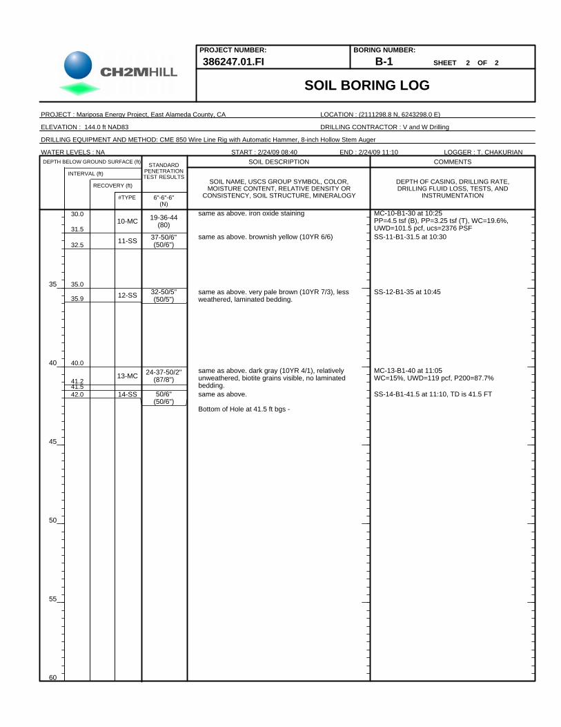
B-1 2111298.8 6243298.0 41.5 144.0
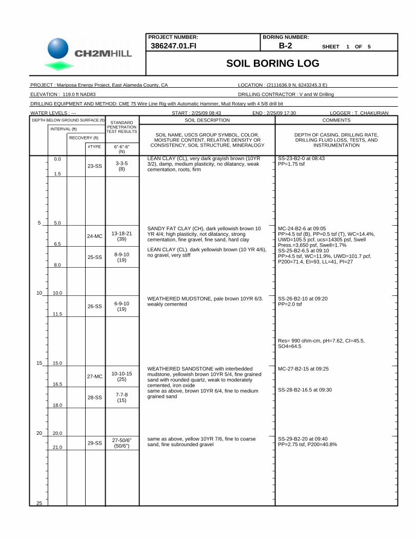
B-2 2111636.9 6243245.3 100 119.0
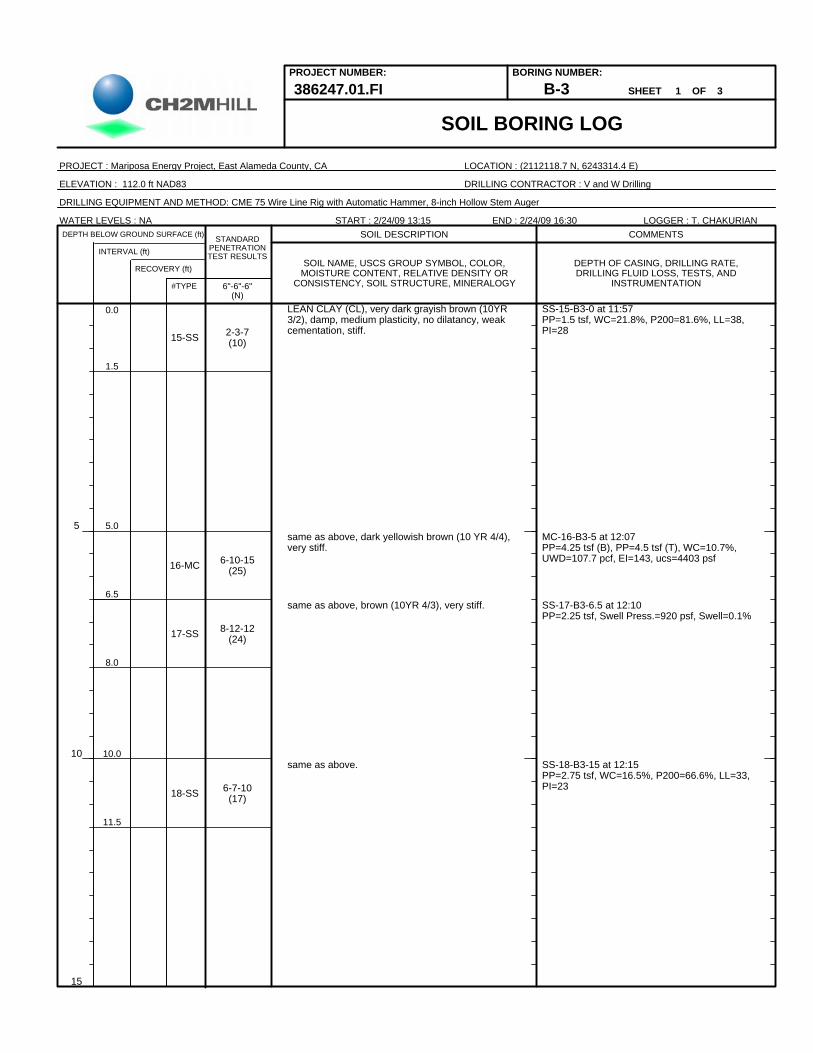
B-3 2112118.7 6243314.4 35 112.0
TP-1 2111309.8 6243238.4 10 136.0
TP-2 2111370.4 6243008.8 10 132.0
TP-3 2111770.5 6243405.3 7 127.0
TP-4 2111440.5 6243125.8 9.5 123.0
TP-5 2111941.2 6243230.3 10 117.0
TP-6 2111966.5 6243410.4 10 117.0
Rain at the site the day before drilling, and subsequent soft ground conditions required the driller to lay timber mats on the ground in front of the drill rig to access the boring locations.
The first boring (B-1) was drilled to a final depth of 35 feet with an 8-inch, hollow-stem auger. During the second boring (B-3), drilling with a hollow-stem auger met refusal and broke the bit at a depth of 23 feet bgs. Unable to continue drilling through the bedrock, the driller abandoned the hole and switched to coring techniques. Because most of the material

GEOTECHNICAL CONDITIONS AND PRELIMINARY RECOMMENDATIONS, MARIPOSA ENERGY PROJECT
EY012009005SAC/386247/091040006 (PRELIM_GEOTECH_REPORT_REVISED_05_04_09.DOC) 4
was not recovered during the first two cores below drilling refusal, it is unclear of the material type that caused refusal. A small amount of weathered conglomerate was encountered in the last portion of the second core. Similarly to Boring B-3, the mud rotary drilling for Boring B-2 met with refusal with at depth of about 34.8 feet bgs. The driller began coring at a depth of 34.8 bgs and encountered very hard andesite.
Soil Classification For this memorandum, soil has been classified using the Unified Soil Classification System (USCS) in accordance with ASTM D2487. In order to determine the relative density and consistency of soils represented by each sample, CH2M HILL calculated a “corrected,” or N60, blow count. The N60 blow count is standardized to account for samplers and hammers other than the standard 2-inch OD split-spoon sampler and the standard safety hammer (140 pounds falling 30 inches). Correction factors presented in Table 2 were used to adjust field blow counts shown on the boring logs for sampler and hammer type.
TABLE 2 Summary of Correction Factors to Blow Counts Shown on Boring Logs Preliminary Geotechnical Design Memorandum – Mariposa Energy Project
Sampler
Drive Method 2.0-inch OD Split Spoon 3.0-inch OD Split Barrel
Automatic Trip Hammer 1.3 0.8
For granular soils, the relative density was based on the corrected blow count using the guidelines presented in Table 3. For cohesive soils, the consistency was based on the following data in order of hierarchy: laboratory measurements of unconfined compressive strength, field pocket penetrometer estimates of unconfined compressive strength, and corrected N60 blow counts. The soils were then assigned relative densities or consistencies based on “corrected” blow counts and the guidelines presented in Table 3.
TABLE 3 Summary of Consistency or Relative Density Preliminary Geotechnical Design Memorandum – Mariposa Energy Project
Soil Type Description
Corrected SPT Blow Count (bpf)
Unconfined Compressive Strength
(tsf)
Very soft 0–1 <0.25
Soft 2–4 0.25–0.50
Firm 5–8 0.50–1.00
Stiff 9–15 1.00–2.00
Very stiff 16–30 2.00–4.00
Cohesive (silts and clays)
Hard >30 >4.00

GEOTECHNICAL CONDITIONS AND PRELIMINARY RECOMMENDATIONS, MARIPOSA ENERGY PROJECT
EY012009005SAC/386247/091040006 (PRELIM_GEOTECH_REPORT_REVISED_05_04_09.DOC) 5
TABLE 3 Summary of Consistency or Relative Density Preliminary Geotechnical Design Memorandum – Mariposa Energy Project
Soil Type Description
Corrected SPT Blow Count (bpf)
Unconfined Compressive Strength
(tsf)
Very loose 0–4 —
Loose 5–10 —
Medium dense 11–30 —
Dense 31–50 —
Non-Cohesive (sands and gravels)
Very dense >50 —
Source: Sowers, 1979 bpf = blows per foot
Laboratory Testing Samples obtained during drilling were transported to a soil testing laboratory. The samples were tested for moisture content, dry density, gradation, Atterberg limits, unconfined compressive strength, expansion index, swell/consolidation and R-value. Results are presented on the boring logs provided in Attachment 1. Laboratory test data are presented in Attachment 2. Tables 4 and 5 summarize the geotechnical test results by primary soil type.
TABLE 4 Summary of Test Results for Characterization Preliminary Geotechnical Design Memorandum – Mariposa Energy Project
Percent < No. 200 Sieve Atterberg Limits
USCS Type No. of Tests Range
No. of Tests
Range of Liquid Limit
Range of Plasticity
Index
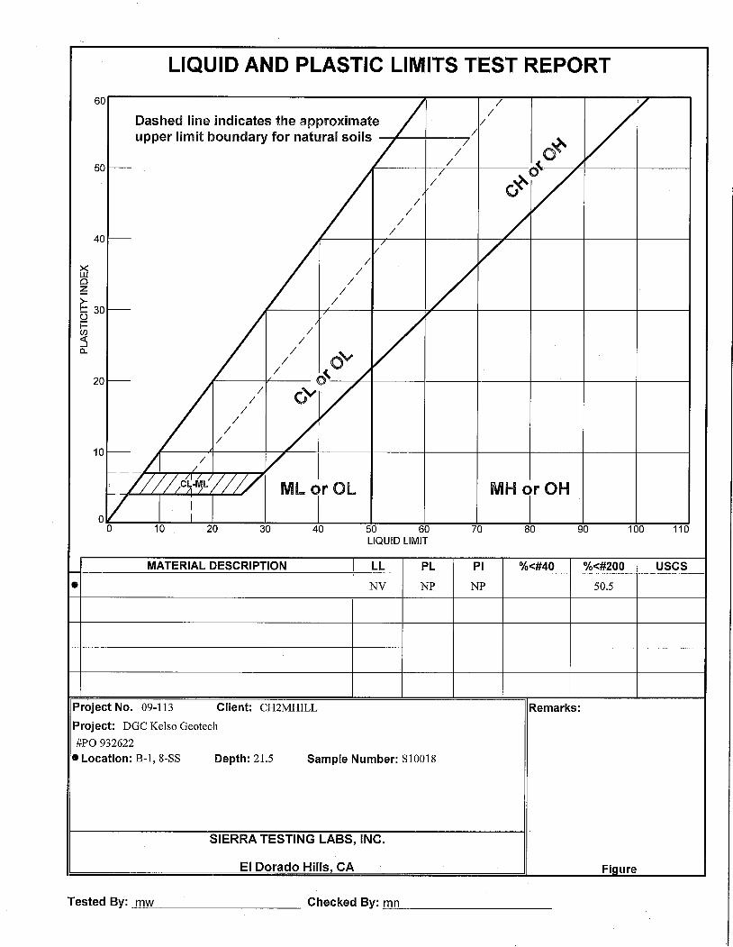
Lean Clay (CL) 4 63 to 82 4 33 to 41 22 to 28
Mudstone (Claystone) 4 63 to 74 4 52 to 92 36 to 54

GEOTECHNICAL CONDITIONS AND PRELIMINARY RECOMMENDATIONS, MARIPOSA ENERGY PROJECT
EY012009005SAC/386247/091040006 (PRELIM_GEOTECH_REPORT_REVISED_05_04_09.DOC) 6
TABLE 5 Summary of Test Results for Strength Preliminary Geotechnical Design Memorandum – Mariposa Energy Project
Corrected Blow Count (bpf)
Unconfined Compressive Strength
(tsf) Pocket Penetrometer
(tsf)
USCS /Rock Type No. of Tests Range
No. of Tests Range
No. of Tests Range
Lean Clay (CL) 7 5 to 31(18)* 1 2.2 7 1.25 to 4.5 (3)*
Sandy Fat Clay (CH) 1 31 1 7.2 2 0.5 to >4.5 (2.5)*
Clayey Sand (SC) 1 49 1 — — —
Sandstone 21 20 to > 50/3” 1 14.4 — —
Andesite — — 1 749 — —
Mudstone (Claystone) 1 25 5 1.5-2.5 — —
*- average value 50/3” = 50 blows for 3 inches
TABLE 6 Summary of Test Results for Swell/Consolidation Preliminary Geotechnical Design Memorandum – Mariposa Energy Project
Consolidation Test
USCS/Rock Type No. of Tests
Overburden Pressure
(tsf) Preconsolidation
Pressure (psf)
Swell Pressure
(psf) Swell (%) Cv Cs
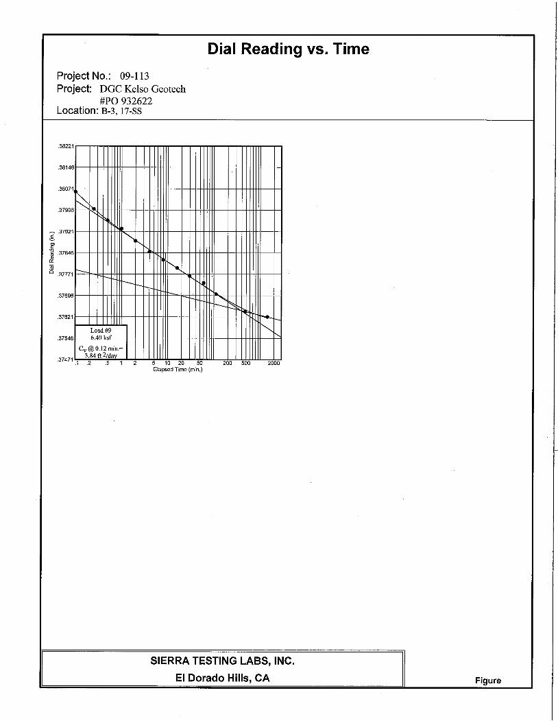
Lean Clay (CL) 1 0.39 1.60 0.46 0.1 0.06 0.01
Sandy Fat Clay (CH) 1 0.30 1.58 1.83 1.7 0.10 0.03
psf = pounds per square foot tsf = tons per square foot
Corrosion Potential and Expansion Index of the Native Soils Two soil samples were submitted to Environmental Technical Services of Petaluma, California, and one sample was submitted to Sunland Analytical in Rancho Cordova, California, for analysis of resistivity, pH, and chloride and sulfate concentrations to assess the corrosivity of the native soils. Composite Sample 1 was a composite of clayey soil from the test pits. Composite Sample 2 was a composite of sandy soil (sandstone) from the test pits. The third sample was from Boring B-2 at a depth of 15 feet bgs in mudstone. Additionally, two soil samples were tested for expansion index and swell potential by Sierra Testing Laboratories of El Dorado Hills, California. Results of the laboratory analyses are included in Attachment 2 and are summarized in Table 7. The soil samples submitted for this testing were collected from depths between the surface and 15 feet bgs.

GEOTECHNICAL CONDITIONS AND PRELIMINARY RECOMMENDATIONS, MARIPOSA ENERGY PROJECT
EY012009005SAC/386247/091040006 (PRELIM_GEOTECH_REPORT_REVISED_05_04_09.DOC) 7
TABLE 7 Summary of Test Results for Corrosivity and Expansion Index Preliminary Geotechnical Design Memorandum – Mariposa Energy Project
Sample Soil Type pH Sulfates (ppm)
Chlorides (ppm)
Resistivity (ohm-cm) Expansion Index
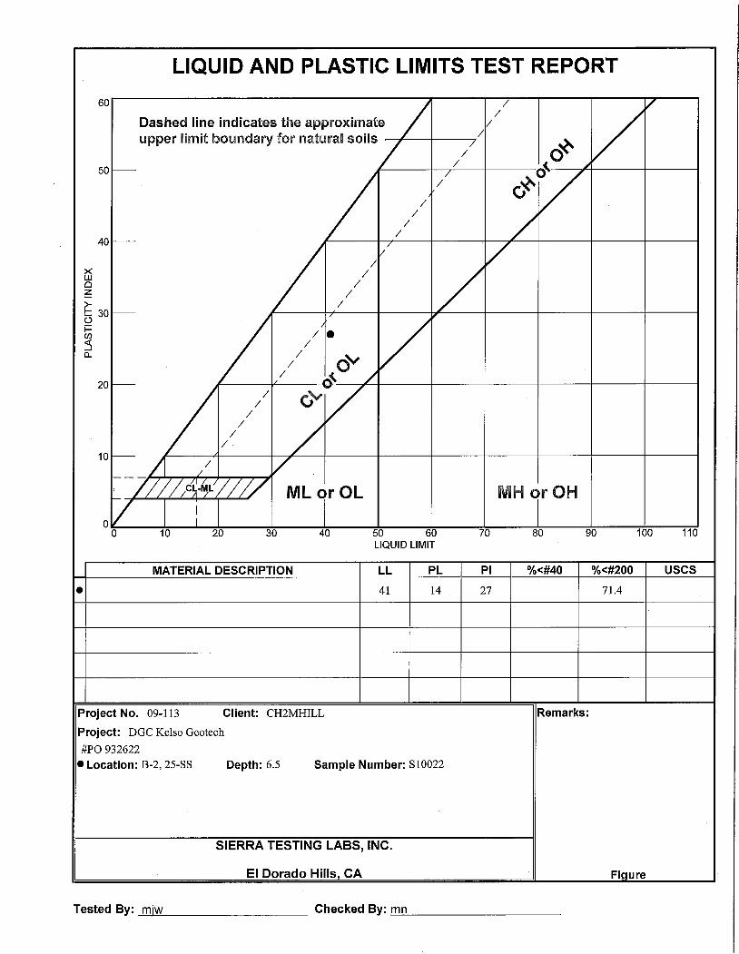
B-2 @ 6.5’ bgs CL — — — — 93
B-2 @ 15’ bgs Interbedded Mudstone
7.62 64.5 45.5 990
B-3 @ 5’ bgs CL — — — — 143
Composite Sample 1
CL 7.84 4.3 53.4 1,050 —
Composite Sample 2
Sandstone 7.84 4.3 53.4 1,050 —
ohm-cm = ohms-centimeters ppm = parts per million
Site Conditions Surface Conditions As discussed previously, the site slopes to the north between two gentle sloping hills. Figure 3 shows the general topography of the project site. The site is generally open and vegetated with short grass. There are no improvements at the site; however, a number of abandoned wind turbine foundations are located on the eastern and western ridge. An existing cogeneration plant is located northeast of the site. Unpaved road access exists at the site, as can be seen in Figure 3.
Regional and Site Geology The site is in the western portion of the San Joaquin Valley, a portion of the Great Valley, bordered by the Sierra Nevada Mountains to the east, the Coast Ranges to the west, the Transverse Ranges and the Mojave Desert to the south, and the Klamath Mountains to the north. The site is mapped as being underlain by Unit D of the Great Valley Sequence, defined as late cretaceous sandstone with adjacent units of shale as shown in Figure 2. The sandstone dips generally to the northeast from 15 to 37 degrees.
Seismicity Faulting. The site is not within a designated Alquist-Priolo zone (Hart and Bryant, 1999). The nearest active fault is Segment 7 of the Great Valley Fault System. This fault segment is considered a reverse blind thrust fault that does not extend to the ground surface.
The Midway Fault is located approximately 1.4 miles west of the site (Unruh and Krug, 2007), but is not officially recognized by the United States Geologic Society (USGS) nor the California Geologic Society (CGS) as a quaternary fault (having movement within the last 1.6 million years). Recently published information suggests the fault should be considered active and was assigned a maximum moment magnitude of 6.3, and a slip rate of 0.2 millimeters a year (Unruh and Krug, 2007; AEG, 2005). The average recurrence interval
GEOTECHNICAL CONDITIONS AND PRELIMINARY RECOMMENDATIONS, MARIPOSA ENERGY PROJECT
EY012009005SAC/386247/091040006 (PRELIM_GEOTECH_REPORT_REVISED_05_04_09.DOC) 8
for the fault is 2,651 years (Wesnousky, 1986). Despite conflicting opinions, the majority of evidence suggests the Midway Fault is a right lateral structure.
Table 8 lists known CGS active faults having the most potential to cause moderate ground shaking at the site. The faults in the list were identified as generating deterministic peak site accelerations greater than 1.0g (EQFAULT, 2004).
TABLE 8 Significant Seismic Sources Preliminary Geotechnical Design Memorandum – Mariposa Energy Project
Fault Fault Typea CGS Fault
Classa
Slip Rate (millimeters per year)a
Maximum Moment
Magnitude (Mw) b
Approximate Site-to-Source
Distance (miles)c
Great Valley Segment 7 Thrust B 1.5 6.7 6 Greenville (North) Strike-Slip B 2.0 6.7 7 Mount Diablo Thrust B 2.0 6.7 8 Calaveras (North, Central, South)
Strike-slip B 6 6.9 19
Great Valley Segment 5 Thrust B 1.5 6.5 22 Hayward (Total) Strike-slip B 9.0 7.3 25 San Andreas Fault (1906) Strike-slip A N/A 7.9 44 a California Geological Survey, 2002. b USGS National Seismic Hazard Maps Fault parameters (2002). c EQFAULT, 2004
Seismic Hazards. The USGS Liquefaction Susceptibility Map of the San Francisco Bay Area shows that the site has very low liquefaction susceptibility (USGS, 2006). There are no other published seismic hazard maps for the site. The site is mapped as having no evidence of historic landslides (Robertson et. al, 1999) and no evidence of landslides was observed at or around the site. Areas to the south, where steeper slopes are present, such as in the vicinity of Altamont Pass, have been subject to landslides.
The seismic hazards at the site are considered to be minimal. No active faults were mapped as crossing the site and the potential for ground rupture, tectonic creep, and seismically induced settlement is considered low. Liquefaction is not anticipated to occur because no groundwater was encountered at the site and no deposits of loose sand were detected during the investigation.
Subsurface Conditions Subsurface conditions encountered in the three borings and six test pits generally consisted of clayey soil over sandstone with interbedded mudstone (claystone) and very hard andesite layers.
Soil. In the borings, the soil consisted primarily of stiff to hard lean clay (CL) with occasional pockets of sandy fat clay (CH), clayey sand (SC), and gravelly lean clay (CL). The test pits encountered similar lean clay (CL). The clays are thought to be residual in nature, derived from weathering of the local bedrock.

GEOTECHNICAL CONDITIONS AND PRELIMINARY RECOMMENDATIONS, MARIPOSA ENERGY PROJECT
EY012009005SAC/386247/091040006 (PRELIM_GEOTECH_REPORT_REVISED_05_04_09.DOC) 9
Corrected blow counts for the lean clay ranged from 5 to 31 bpf with an average value of 18 bpf. Pocket penetrometer measurements of unconfined compressive strength obtained in the field in this material ranged from 1.25 to more than 4.5 tsf, with an average value of 3 tsf. A single sample of the lean clay at a depth of 5 feet in Boring B-3 reported a laboratory unconfined compressive strength of 2.2 tsf
The blow count in the sandy fat clay encountered in Boring B-2 at a depth of 5 feet was 31 bpf. The laboratory unconfined compressive strength of the sandy fat clay was 7 tsf. Using the pocket penetrometer, measurements of unconfined compressive strength obtained in the field in this material ranged from 0.5 to more than 4.5 tsf, with the average value of 2.5 tsf.
Based on the results of the expansion index testing, samples of the native clays are considered to possess high to very high expansion potential (CBC, 2002). Two consolidation tests were conducted at the site. The tests show the sandy fat clay has high swell potential, while the lean clay has low swell potential (O’Neill and Poormayed, 1980). The sandy fat clay has 1.7 swell percentage with a swell pressure of 3,650 psf. The lean clay has 0.1 swell percentage with a swell pressure of 920 psf. Both consolidation tests indicate that the sandy fat clay and the lean clay are overconsolidated, which is consistent with the residual nature of the soil at the site.
The soils should also be considered corrosive to buried ferrous metals including steel, ductile iron, cast iron, and galvanized steel due to low resistivity (Caltrans, 2003). The soils are not considered corrosive to buried concrete and cement mortar surfaces due to low chlorides and sulfate concentrations
Rock. Sandstone with interbedded mudstone (claystone), mudstone, and very hard andesite dikes were encountered underlying these surface soils in the borings. A 1-foot layer of very hard conglomerate was also encountered in boring B-3 at a depth of 23 feet bgs. Weathered sandstone was encountered in the test pits at the site. In TP-2, a dip of about 35 degrees was measured. Based on the reported dips shown in Figure 2 and the measured dip, a 35 degree dip was assumed for the site.
The laboratory unconfined compressive strength was 14.4 tsf for the sandstone and 749.0 tsf for the andesite. The andesite sample tested was from a depth of 93 feet in Boring B-2 as it was the only recovered andesite core suitable for testing. Andesite encountered at a depth of 34.8 feet and at other depths in Boring B-2 likely has a similar high strength. The hard andesite and the conglomerate encountered below elevation 84 feet will likely make installation of deep driven or drilled foundations very difficult and rock drilling may be required to allow any deep foundations to advance and develop necessary design capacity.
The laboratory unconfined compressive strength of the interbedded mudstone ranged from 1.9 to 2.3 tsf. The moisture content of the interbedded mudstone ranged from 31.3 to 38.7 percent. For the interbedded mudstone, the percent passing the number 200 sieve ranged from 62.7 to 73.8 percent.
No swell tests were conducted on the mudstone layers; however, the mudstone layers have a high liquid limit and may be expansive.

GEOTECHNICAL CONDITIONS AND PRELIMINARY RECOMMENDATIONS, MARIPOSA ENERGY PROJECT
EY012009005SAC/386247/091040006 (PRELIM_GEOTECH_REPORT_REVISED_05_04_09.DOC) 10
Groundwater. Groundwater was not encountered in the borings and test pits at the time of the investigation. No historic groundwater data are available for the site.
Conclusions and Recommendations Seismic Design The results of the probabilistic site hazard analysis were derived for the project site based on information obtained from the USGS National Seismic Hazard Maps (USGS, 2008a). The maximum credible earthquake (MCE) by the California Building Code (CBC, 2007) has recurrence interval of 2,475 years or 2 percent probability of exceedance in 50 years.
Design Values. The National Seismic Hazard Maps indicate that the peak bedrock acceleration (PBA) at the site is 0.60g for a 2,475 years recurrence interval or 2 percent probability of exceedance in 50 years. Given the shallow bedrock at the site, this value may also be considered the peak ground acceleration (PGA) for design. During the final design, the shear wave velocity should be measured to confirm this estimate. The design ground motion is based on 2/3 of the MCE per the 2007 CBC. From the Earthquake Ground Motion Parameter Calculator (USGS, 2008b) the following parameters in Table 9 may be used for seismic design of the improvements using the 2007 California Building Code.
TABLE 9 2007 California Building Code Site Class and Site Seismic Coefficients Preliminary Geotechnical Design Memorandum – Mariposa Energy Project
Designation Value Reference
Soil Profile Type Site Class C Table 1613.5.2
Spectral Response Acceleration for MCE at 0.2 second period
Ss 1.50 Figure 1613.5 (3)
Spectral Response Acceleration for MCE at 1 second period
Sf 0.521 Figure 1613.5 (4)
Site Parameter Fa 1.0 Table 1613.5.3 (1)
Site Parameter Fv 1.3 Table 1613.5.3 (1)
Spectral Response Acceleration at 0.2 second period
SMS 1.500 Equation 16A-37
Spectral Response Acceleration at 1 second period
SM1 0.678 Equation 16A-37
Design Spectral Acceleration Parameter at 0.2 second period
SDS 1.000 Equation 16A-39
Design Spectral Acceleration Parameter at 1 second period
SD1 0.452 Equation 16A-40
Site Class C was calculated according to the California Building Code (2007). The field blow counts per foot were averaged to a depth of 100 feet bgs. For blow counts not recorded, the blow counts were estimated using blow counts in similar adjacent material. For the blow

GEOTECHNICAL CONDITIONS AND PRELIMINARY RECOMMENDATIONS, MARIPOSA ENERGY PROJECT
EY012009005SAC/386247/091040006 (PRELIM_GEOTECH_REPORT_REVISED_05_04_09.DOC) 11
counts that met with refusal and for the bedrock cores, a blow count of 100 bpf were used in the estimate.
The National Seismic Hazard Maps and the Earthquake Ground Motion Parameter Calculator does not explicitly account for the Midway Fault in the probabilistic PBA because the fault was not included in the seismic sources. However, the PBA component from the Midway Fault is likely small, as mentioned previously, the average recurrence interval is 2,651 years. In comparison, the San Andreas, the Calaveras (North), and the Greenville faults have respective recurrence intervals of 400, 300, and 550 years. For the final geotechnical work, the seismicity of the Midway Fault should be explicitly modeled and its contribution accounted for in the PBA to confirm that its contribution is considered minor.
Earthwork The following earthwork and related activities will be performed during construction:
• Excavation and site pad preparation • Foundation construction • Backfill and surface restoration
Excavation and Site Pad Preparation. Construction areas should be cleared and grubbed of all surface and subsurface materials and structures, including vegetation, organic topsoil, pavement, abandoned utilities, and any other deleterious substances that conflict with the proposed construction. Cleared and grubbed material should be disposed of offsite, and should not be used as fill or backfill material.
Cuts of up to 32 feet are planned along the eastern portion of the site, and fills of up to 15 feet are planned along the central and western portions of the site. Approximately 45 percent of the proposed site will be located within bedrock cut while the remainder of the site will be underlain by compacted fill.
As discussed previously, the bedrock contains interbedded layers of sandstone and expansive mudstone that dip toward the northeast. The proposed site grading plan will expose this dipping bedrock along the majority of the eastern portion of the site, where it will constitute the finished grade. There is a potential for differential movement and swell if foundations bear directly on the interbedded bedrock. Therefore, it is recommended that the upper 2 feet of bedrock beneath the portion of the site where it represents the finished grade be removed, moisture conditioned, blended, and compacted to a minimum of 95 percent relative compaction in accordance with ASTM D1557 to provide a more uniform bearing surface.
For the areas of fill, the residual clay soils appear to possess high swell potential. At this time, it is not known whether the mudstone bedrock or the remolded composite samples of the clays, mudstones, and sandstones possess the same swell potential.
Discussed previously, the surface layer of residual clay within the existing valley appears to become thicker toward the north. At Boring B-3, approximately 15 feet of clay is present below the ground surface. Because the fills of up to 15 feet of soil at the north end of the foundation pad will place an additional pressure on the thicker clay soils, it is estimated that up to 1 inch of post-construction consolidation (settlement) or swell of the native clay soils

GEOTECHNICAL CONDITIONS AND PRELIMINARY RECOMMENDATIONS, MARIPOSA ENERGY PROJECT
EY012009005SAC/386247/091040006 (PRELIM_GEOTECH_REPORT_REVISED_05_04_09.DOC) 12
will occur. With laboratory test results from samples of clay obtained during final design, the actual swell or consolidation should be better defined.
For portions of the site pad fill greater than 10 feet in thickness and for fill beneath the turbines, select granular fill derived from on-site sandstone or imported material containing less than 30 percent passing the number 200 sieve should be placed and compacted to a minimum of 95 percent relative compaction. It is estimated that approximately half of the planned cut on the eastern side of the slope will encounter sandstone materials that will meet the requirements for select granular fill. This suggests that 36,000 of the required 66,000 cubic yards of fill material will likely be suitable for use in the deeper fills and beneath the turbines. Because this preliminary estimate was made using data from a single soil boring (B-1) and shallow test pits, it should be confirmed during final design with additional investigation.
The moisture content of fill materials should be adjusted as necessary to obtain the specified compaction. Loose lifts of fill should not exceed 8 inches in thickness if heavy equipment is used. If hand-operated equipment is used, loose lifts of fill should not exceed 6 inches in thickness. All excavations should be free of standing water or loose material before any fill or concrete is placed.
Cut Slope. The proposed 3:1 cut slope into the eastside slope was modeled and analyzed with the computer program Slide 5.0 (Rocscience, 2009) to evaluate stability of the slope. In the computer model, the 3:1 cut slope was made in sandstone. The sandstone was modeled with a 35 degree dip into the cut slope (favorable). At a slope height of 32 feet, the factor of safety against failure was greater than 3.
Because of the unfavorable bedrock dip on the western site slope, it is recommended to avoid cuts of more than a few feet at the toe of this slope to reduce the potential for sliding and movement of the stratified bedrock onto the site.
Fill Slope. It is recommended to slope the constructed embankment slopes at 3:1 (H:V).
Foundations and Settlement Four gas turbines are planned for the site. Each turbine is approximately 55 feet long, 14 feet wide, and weighs approximately 350 tons. Turbines are typically founded on reinforced concrete mat foundations with a typical thickness of 3 feet. Bearing pressure would be anticipated to be approximately 1,000 psf. Based on the site grading plan, it is anticipated that the turbines and associated exhaust stacks will bear on excavated native sandstones and mudstones, with the turbines of Units 3 and 4 (northern most turbines) bearing on compacted select granular site fill ranging in thickness to 4 feet.
In a similar manner the administration building and the water tanks are planned to partially bear on both excavated bedrock and select granular fill. The compacted select granular site fill across the site will in turn bear on a layer of the expansive native lean and fat clays that range in thickness up to 4 feet. In order to mitigate the risk of differential settlement and cracking of the turbine foundations at Units 3 and 4 and the administration building and water tanks, it is recommended to overexcavate the native clay soils from beneath the turbines of Units 3 and 4, the administration building, and tanks and replace the overexcavated material with moisture conditioned and compacted select granular fill.
GEOTECHNICAL CONDITIONS AND PRELIMINARY RECOMMENDATIONS, MARIPOSA ENERGY PROJECT
EY012009005SAC/386247/091040006 (PRELIM_GEOTECH_REPORT_REVISED_05_04_09.DOC) 13
The warehouse, power distribution center, and fuel gas compressor are planned to bear on fills with thicknesses of over 10 feet, and therefore will be comprised per the recommendation above, of select granular fill. The transformers will instead bear on compacted native fills of thicknesses of less than 10 feet.
The maximum net allowable bearing pressure for foundations bearing in the fill shall be 2,000 psf and for foundations bearing in the select fill, it shall be 2,500 psf. For foundations bearing entirely on the excavated bedrock the net allowable bearing pressure shall be 3,000 psf. Allowable bearing pressures may be increased by one-third for transient loading conditions. Consolidation or swell of the native clay soils beneath the fill is likely to be less than 1 inch, as the applied fill pressure is less than 1,500 psf. Movement of the turbine foundations with a bearing pressure of 1,000 psf is also estimated to be less than 1 inch. These estimates should be verified by additional soils testing during final design.
For areas of shallow fill where the foundations will bear on native clays or where the native clays are within 24 inches of the foundation (such as the south end of the project and along the boundaries of cut and fill), foundations with net bearing pressures of 2,000 psf or less may experience swell equal to 1 to 2 percent of the thickness of the underlaying clay layer, or approximately 1 to 3 inches of movement. Therefore, it is recommended to remove, moisture-condition, and recompact 24 inches of the native clays beneath the lowest foundation bearing depth.
As stated previously, settlement and swell potential of the native clays across the site will need to be addressed in final design with the collection of additional swell and consolidation test data. If additional testing during final design indicates that settlement or swell is an issue for the warehouse, power distribution center, and fuel gas compressors, it is recommended to consider the following options to address post-construction movement of the tanks:
1. Overexcavate the native clay soils and replace them with suitable non-swelling fill prior to placement of the site equipment pad.
2. Install sand columns through the clay and preload the site with additional fill to speed the consolidation process and reduce the settlement potential.
3. Construct the facilities on thick mat foundations to reduce the potential for structural damage related to settlement
All of the stacks and the turbines of Units 1 and 2 are anticipated to bear on native bedrock exposed in the planned cut. As discussed previously, to reduce the potential for differential swell of the bedrock, it is also recommended to remove, moisture-condition, and recompact 24 inches of the native mudstone bedrock beneath the lowest foundation bearing depth. This requirement may be deleted if final design geotechnical data suggest that the bedrock possesses low swell potential. Net allowable bearing pressure in the areas of bedrock cut shall be 3,000 psf.
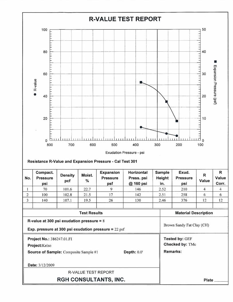
Pavement Design For the proposed paved areas, surface restoration should include asphalt concrete (AC) pavement over an aggregate base. Two R-value tests were performed on composite samples of the surface soils from test pits TP-1 through TP-6. Composite Sample 1 included

GEOTECHNICAL CONDITIONS AND PRELIMINARY RECOMMENDATIONS, MARIPOSA ENERGY PROJECT
EY012009005SAC/386247/091040006 (PRELIM_GEOTECH_REPORT_REVISED_05_04_09.DOC) 14
composite samples of clayey soil and indicated an R-value of 8. Composite Sample 2 included composite samples of weathered sandstone and indicated an R-value of 22.
For private roads in unincorporated areas of Alameda County, the Alameda County Public Works Agency requires private roads to have the following minimums:
• Traffic Index (TI) of 5.5 • AC pavement thickness of 3 inches • 10 inches of aggregate base.
Also, the pavement design shall be based on the criteria in Chapter 600 of the Caltrans Highway Design Manual. As such, the calculated pavement thicknesses are presented in Table 10 for the minimum TI, and TI equal to 7 and 9 using the Caltrans program CalFP Version 1.1. If pavement thicknesses are required for additional TIs, the geotechnical engineer should be contacted. The aggregate base material should be placed on a prepared subgraded and compacted to a minimum 95 percent relative compaction (ASTM D1557). Subgrade preparation should include clearing, grubbing, and stripping topsoil from the area to receive pavement and scarifying the upper 12 inches, moisture conditioning the soil, and compacting the native soils to at least 95 percent relative compaction.
TABLE 10 Preliminary Pavement Thicknesses Preliminary Geotechnical Design Memorandum – Mariposa Energy Project
Traffic Index Asphalt Concrete (Type B)
(feet) Aggregate Base (Class 2)
(feet)
5.5 0.25 0.90
7 0.35 1.20
9 0.45 1.65
Detention Basin A detention basin is planned at the northwestern corner of the site, located at the toe of the planned equipment pad. The planned basin floor elevation is 107 feet msl, which is approximately 5 feet lower than the existing ground surface near the basin discharge point. Test Pit TP-5, located on the western slope, encountered weathered sandstone (sand) at a depth of 4.5 feet bgs. This may indicate that the proposed detention basin will introduce water to the sandstone layer causing water to leak from the basin. As overall basin leakage is not a general concern, except in as far as the potential for piping of fines through sand layers, it is recommended to incorporate a cutoff collar into the discharge piping to reduce the risk of seepage around the planned pipe.
The basin should be constructed of native materials with in excess of 30-percent clay fines to reduce seepage losses.

GEOTECHNICAL CONDITIONS AND PRELIMINARY RECOMMENDATIONS, MARIPOSA ENERGY PROJECT
EY012009005SAC/386247/091040006 (PRELIM_GEOTECH_REPORT_REVISED_05_04_09.DOC) 15
Construction Considerations The ground surface elevation for the proposed site pad is approximately 125 feet msl. At this elevation, the western side of the pad will be on clay soils and the eastern side will be over bedrock.
The soils beneath the site should be excavatable with an excavator of 200 horsepower, with the exception of the layers of andesite and conglomerate encountered at depth. However, the depth of these identified layers and the northeastern dip of the bedrock would suggest that the same layers would be below the proposed cut on the eastern side of the site. Regardless, it is recommended to drill additional borings on the east side to verify that these layers will not complicate excavation of the proposed cut.
Sandy site soils exposed in cut and fill slopes should be protected from erosion and revegetated as soon as possible because these soils will likely be prone to erosion.
For the proposed improvements, it is the responsibility of the contractor to implement sound construction methods and procedures in accordance with local, state, and federal safety standards. Variations in soil and geologic conditions are possible and may be encountered during construction. To permit correlation between the exploration data and the actual conditions encountered during construction, a qualified geotechnical specialist should provide onsite review, as needed, during construction. If unusual conditions are encountered, a geotechnical engineer should be consulted to determine if revisions to the recommendations are needed. It is recommended that a qualified geotechnical specialist, engineer, or engineering geologist inspect the excavation and subgrade preparation to observe the nature of the materials encountered and to verify the adequacy of the subgrade. Compaction testing and periodic fill observations should be performed during placement of engineered fill.
Recommendation for the Final Geotechnical Investigation As stated in CH2M HILL’s original proposal dated January 23, 2009, the following primary issues are to be addressed in the final design geotechnical investigation:
• Nature and strength of native soils beneath specific planned facilities and improvements • Parameters necessary for civil earthwork calculations • Recommendations for final design of deep and/or shallow foundations • Earthwork values necessary for final design of on-and offsite utilities such as gas and water • Recommendations for design of electric transmission towers • Recommendations for design of site access and onsite access roads
The following specific topics require additional investigation and analysis based on the findings of the preliminary geotechnical design effort:
1. Contribution of nearby Midway Fault to the site seismicity 2. Swell or settlement potential of site soils, bedrock, and fill derived from the same
materials 3. Potential presence of hard andesite and conglomerate in the eastern cut slope

GEOTECHNICAL CONDITIONS AND PRELIMINARY RECOMMENDATIONS, MARIPOSA ENERGY PROJECT
EY012009005SAC/386247/091040006 (PRELIM_GEOTECH_REPORT_REVISED_05_04_09.DOC) 16
Site Investigation The final design investigation is planned to provide specific information necessary for final design of the project and to allow ME to obtain necessary construction permits.
Based on the preliminary design and with specific attention to the final design layout of the facilities and proximity to existing subsurface data, three soil borings and six test pits will be completed across the site to obtain samples for laboratory testing and to investigate deep subsurface conditions, and up to 10 soil borings and four test pits will be completed at the locations of transmission towers and along the gas pipeline. One of the 13 borings will be 100 feet deep, two borings will be 25 feet deep, and the remaining borings will be 50 feet deep. The borings will be completed at the specific locations of final design facilities such as the office building, turbines, transmission towers, pipeline, and inlet air cooling facilities.
Down-hole measurements of seismic shear wave velocity will be obtained at one of the boring locations to a depth of 100 feet in order to assess the potential for vibration-induced settlement and to confirm the estimated shear wave velocity at the site. A CH2M HILL geotechnical or geologic professional will log the conditions observed in the borings and will obtain samples suitable for laboratory testing.
Laboratory Testing The assumed testing plan based on the investigation outlined above is provided in Table 11.
TABLE 11 Final Design Laboratory Testing Plan Preliminary Geotechnical Design Memorandum – Mariposa Energy Project
Test Standard Frequency
Corrosivity CAL 643, 417, and 422 4
Gradation ASTM D422 20
Atterberg Limits ASTM D2216 and D4318 20
In situ Unit Weight and Moisture Content ASTM D2937 10
Swell/Collapse Potential ASTM D4546 5
Direct Shear ASTM D3080 15
Unconfined Compressive Strength ASTM D2166 10
Final Design Geotechnical Memorandum CH2M HILL will prepare a final design memorandum that will discuss the implemented field and laboratory testing programs and present the findings. A fee estimate for the final scope of work will be provided to ME in a separate letter. The report will address the following issues:
• Seismic design criteria using CBC 2007 • Foundation design for facilities (tanks, cooling facilities, office, transmission towers,
stacks, and turbines)

GEOTECHNICAL CONDITIONS AND PRELIMINARY RECOMMENDATIONS, MARIPOSA ENERGY PROJECT
EY012009005SAC/386247/091040006 (PRELIM_GEOTECH_REPORT_REVISED_05_04_09.DOC) 17
• Nature and strength of native soils beneath specific planned facilities and improvements • Corrosion design considerations • Parameters necessary for civil earthwork calculations • Recommendations for design of deep and/or shallow foundations • Recommendations for design of the detention basin • Earthwork values necessary for design of onsite utilities and offsite gas and water lines • Recommendations for design of site access and onsite access roads • Earth pressures for retaining wall and belowgrade facility design • Swell potential of the native materials and the moisture-conditioned blend of the
mudstone, sandstone, and clays. • Detailed settlement/swell analysis depending on the final layout of improvements. • Confirmation of the seismic shear wave velocity of the soils and bedrock beneath the site. • Probabilistic analysis of the site seismicity in consideration of the Midway Fault
Limitations This memorandum has been prepared for the exclusive use of ME and CH2M HILL for specific application to the design of the improvements at the Mariposa Energy Project in Alameda County, California. It has been prepared in accordance with generally accepted geotechnical engineering practice. No other warranty, expressed or implied, is made.
The analyses and recommendations contained in this memorandum are based on the data obtained from exploratory borings and test pits for the proposed facility. These explorations indicate subsurface conditions only at specific locations and times, and only to the depths penetrated. They do not necessarily reflect strata variations that may exist between such locations. Subsurface conditions and water levels at other locations may differ from conditions occurring at these locations. The passage of time may result in a change in the conditions at these locations. If variations in subsurface conditions from those described are noted during construction, recommendations in this memorandum must be reevaluated.
In the event that any changes in the nature, design, or location of the facilities are planned, the conclusions and recommendations contained in this memorandum should not be considered valid unless the changes are reviewed and conclusions of this memorandum modified or verified in writing by CH2M HILL. CH2M HILL is not responsible for any claims, damages, or liability associated with the interpretations of subsurface data or reuse of the subsurface data or engineering analyses without the express written authorization of CH2M HILL.
References Alameda County Public Works Agency, 2008, Engineering Design Guideline for Unincorporated Alameda County, Hayward, CA.
Association Engineering Geologists. 2005. An Updated Characterization of the Midway Fault, Alameda County, California. San Francisco Section Newsletter, February 2005.
Blake, T. 2004. EQFAULT V. 3.00b. Thomas F. Blake Computer Services and Software, Thousand Oaks, CA.

GEOTECHNICAL CONDITIONS AND PRELIMINARY RECOMMENDATIONS, MARIPOSA ENERGY PROJECT
EY012009005SAC/386247/091040006 (PRELIM_GEOTECH_REPORT_REVISED_05_04_09.DOC) 18
California Department of Transportation (Caltrans). 2003. California Department of Transportation Division of Engineering Services—Materials Engineering and Testing Services, Corrosion Technology Branch. Corrosion Guidelines. Version 1.0. September.
California Department of Transportation (Caltrans). 2009. CalFP Version 1.1
California Geological Survey (CGS). 2002. Probabilistic Seismic Hazard Assessment Maps (probabilistic site hazard analysis) http://www.conservation.ca.gov/cgs/rghm/psha/ index.htm.
Hart, E. and W. A. Bryant. 1999. Fault-Rupture Hazard Zones in California (Alquist-Priolo Special Studies Zones Act of 1972 with Index to Special Studies Zones Maps), California Division of Mines and Geology Special Publication 42, Revision 2.
International Conference of Building Officials (ICBO). 2002. Uniform Building Code.
O’Neil, M.W., and N. Poormoayed. 1980. Methodology for Foundations on Expansive Clays. Journal of Geotechnical Engineering Division, American Society of Civil engineers, Vol. 106, No. GT12, pp. 1345-1367.
Robertson, S., Roberts, M., and Brennan, E. 1997. Landslides In Alameda County, California, A Digital Database Extracted from Preliminary Photointerpretation Maps Of Surficial Deposits By T.H. Nilsen Inusgs Open-File Report 75-277. United States Geological Survey. Open-File Report 99-504.
Rocscience. 2009. Slide 5.039. Toronto, Ontario
Seed, R.B., H.O. Cetin, R.E.S. Moss, A.M. Kammerer, J. Wu, J.M. Pestana, and M.F. Riemer. 2001. Recent Advances in Soil Liquefaction Engineering and Seismic Site Response Evaluation. Proceedings of the Fourth International Conference on Recent Advances in Geotechnical Earthquake Engineering and Soil Dynamics and Symposium in Honor of Professor W.D. Liam Finn. San Diego, CA. March.
Sowers, G. 1979. Introductory Soil Mechanics and Foundations. Fourth Edition. Prentice Hall. May.
United States Geological Survey (USGS). 1996. Preliminary Geologic Map Emphasizing Bedrock Formations in Alameda County, California. File Report 96-252
United States Geological Survey (USGS). 2002. National Seismic Hazard Maps Fault Parameters, Quaternary Fault and Fold Database of the United States http://earthquake.usgs.gov/regional/qfaults. Website accessed November 2006.
United States Geological Survey (USGS). 2005. Conterminous U.S., Gridded Data Values 2002, revised October 2003 and Interactive Deaggregation. USGS website, http://earthquake.usgs.gov/research/hazmaps/ interactive/index.php. Website accessed April 2009.
United States Geological Survey (USGS). 2006. USGS Susceptibility Map of the San Francisco Bay Area, San Francisco Bay Region Geology and Geologic Hazards. USGS website, http://geomaps.wr.usgs.gov/sfgeo/liquefaction/susceptibility.html. Website accessed April 2009.

GEOTECHNICAL CONDITIONS AND PRELIMINARY RECOMMENDATIONS, MARIPOSA ENERGY PROJECT
EY012009005SAC/386247/091040006 (PRELIM_GEOTECH_REPORT_REVISED_05_04_09.DOC) 19
United States Geological Survey (USGS). 2008a. National Seismic Hazard Maps. http://gldims.cr.usgs.gov/nshmp2008/viewer.htm
United States Geological Survey (USGS). 2008b. Earthquake Ground Motion Parameter Calculator, Version 5.0.9, Dated 10/06/2008, http://earthquake.usgs.gov/research/hazmaps/design/
Unruh, J., and K. Krug. 2007. Assessment and Documentation of Transpressional Structures, Northeastern Diablo Range, for Quaternary Fault Map Database: Collaborative Research with William Lettis & Associates, Inc and the U.S. Geological Survey. Award Number 06HQGR0139.
Wagner D.L., E. J. Bortugno, and R.D McJunkin. 1990. Geologic map of the San Francisco-San Jose Quadrangle. California Department of Conservation. Division of Mines and Geology. Map No. 5A.
Wesnousky, S. G. 1986. Earthquakes, Quaternary Faults and Seismic Hazard in California, Journal of Geophysical Research, Vol. 91, No. B12, pp. 12,587-12,631.

Figures
\

\\ZION\SACGIS\PROJ\DIAMOND_376670\MAPFILES\AFC_MAPS\VICINITYMAP.MXD SSCOPES 4/14/2009 11:53:43
_̂
Project Site
CONTRA COSTA COUNTY
STANISLAUS COUNTY
ALAMEDA COUNTY
SANTA CLARA COUNTY
SAN JOAQUIN COUNTY
SOLANO COUNTY
§̈¦5
§̈¦580
§̈¦680
§̈¦205
§̈¦880
§̈¦680
§̈¦580
UV99
UV33
UV12
UV120
UV88
UV84
UV26
UV26 UV4
UV12
UV4
UV160
UV99
UV4
UV130
UV130UV130
UV132
UV4
Lodi
Tracy
Oakley
Dublin
Antioch
MantecaLathrop
Clayton
Stockton
Milpitas
Brentwood
Alum Rock
Livermore
Pittsburg
Pleasanton
Blackhawk-Camino Tassajara
0 63
Miles
LEGEND
_̂ PROJECT SITE
COUNTY BOUNDARIES$ FIGURE 1
PROJECT VICINITYMARIPOSA ENERGY PROJECTALAMEDA COUNTY, CALIFORNIA

SAC\\ZION\SACGIS\PROJ\DIAMOND_376670\MAPFILES\AFC_MAPS\GEOTECH_GEOLOGYMAP.MXD MHASKELL 5/1/2009 11:34:59
Qu
Midway Reverse Fault
West Tracy Thrust Fault
Kd
QuTol
Tn
Kd
Tol
Tn
Kd
Qt
Kd
KelQu
Kd
Qt
Kd Qu
Kd
Kd
Kds
Kds
Kel
Qu
Kds
Kd
Qt
Kds
Kds
Kds
Qu
Kd
Qu
Qu
36
1523
28
34
27
30
27
Kelso Rd
Bru
ns R
d
0 4,0002,000
Feet
LEGENDMEASURED BEDROCK STRIKE AND DIP (DEGREES)ACCESS ROADCONSTRUCTION LAYDOWN/PARKING AREAPROJECT SITETWO MILE RADIUS
GEOLOGY TYPEQt - Terrace deposits (Holocene(?) and Pleistocene)Qu - Surficial deposits, undivided (Holocene and Pleistocene)Tn - Neroly Sandstone (late Miocene)Tol - Oro Loma Formation of Briggs (1953) (Pliocene)
GREAT VALLEY SEQUENCEKd - Unit D - Sandstone (Late Cretaceous)Kds - Shale memberKel - Unit E, lower member (Late Cretaceous)
This map was compiled from various scale source data and maps and is intended for use as only an approximate representation of actual locations.
FIGURE 2GEOLOGIC MAPMARIPOSA ENERGY PROJECTALAMEDA COUNTY, CALIFORNIA
Sources:Faults: Unruh & Krug, 2007; USGS 1996aGeology: U.S. Dept of the Interior, USGS, 1996b
NOTE: ORIGINAL FIGURE REPRODUCED IN COLOR

SAC\\ZION\SACGIS\PROJ\DIAMOND_376670\MAPFILES\AFC_MAPS\GEOTECH_TOPO.MXD MHASKELL 4/29/2009 18:21:13
EXHAUST STACK
EXHAUST STACK
EXHAUST STACKEXHAUST STACK
RAW WATER STORAGE TANK
GAS TURBINE GENERATOR(TYP. OF 4)
GENERATOR STEP-UPTRANSFORMER
(TYP. OF 4)
ACCESS ROAD
1FT CONTOURS
145
140
135
130
140
160
155
150
145
135
130
125
120
175
170
165
160
155
150
145
140
135
130
125
DETENTION BASIN
PROCESS WASTEWATERSTORAGE TANK
DEMINERALIZEDTANK
WAREHOUSE / MAINTENANCEBUILDING
POWERDISTRIBUTION CENTER AIR COOLED
CONDENSER
DISCONNECT
B-3
B-2
B-1
TP-6
TP-5
TP-4
TP-3
TP-2
TP-1
0 15075
Feet
LEGEND
APPROXIMATE SOIL BORING LOCATIONSEXISTING TURBINE FOUNDATIONSAPPROXIMATE TEST PIT LOCATIONS
This map was compiled from various scale source data and maps and is intended for use as only an approximate representation of actual locations.
FIGURE 3SITE PLANMARIPOSA ENERGY PROJECTALAMEDA COUNTY, CALIFORNIA

ATTACHMENT 1
Project Boring and Test Pit Logs

SAMPLES:BU: BULK SAMPLEMC: MODIFIED CALIFORNIA SPLIT SPOON SAMPLE SS: SPLIT SPOON SAMPLE
UNITS AND COMMENTS:(B): BOTTOM(T): TOPNP: NOT PLASTICNV: NOT VALIDPCF: POUNDS PER CUBIC FOOTPPM: PARTS PER MILLIONPSF: POUNDS PER SQUARE FOOT TSF: TONS PER SQUARE FOOT
DRILLING AND SAMPLING ABBREVIATIONS
WATER LEVELS INDICATED ON THE BORING LOGS ARE THE LEVELS MEASURED IN THE BORINGS AT THE TIMES INDICATED. GROUNDWATER LEVELS AT OTHER TIMES AND OTHER LOCATIONS ACROSS THE SITE COULD VARY. THE ACCURACY OF THE GROUNDWATER LEVEL READINGS IS BASED ON THE TYPE OF SOIL AND THE PERIOD OF OBSERVATION.
WATER LEVELS:
ASTM STANDARD: THE SOIL CLASSIFICATIONS ON THE LOGS ARE BASED ON THE UNIFIED SOIL CLASSIFICATION SYSTEM (USCS), AND ARE IN GENERAL ACCORDANCE WITH ASTM D2488, VISUAL-MANUAL PROCEDURE FOR DESCRIPTION OF SOILS AND ASTM D2487, CLASSIFICATION OF SOILS FOR ENGINEERING PURPOSES. SEE THE ASTM STANDARD FOR A COMPLETE DESCRIPTION, SELECT SUMMARY OF THE CLASSIFICATIONS PROVIDED BELOW.
SOIL CLASSIFICATION
SPT N-VALUE (BLOWCOUNTS): THE NUMBER OF BLOWS REQUIRED TO DRIVE THE STANDARD 2-INCH O.D. SPLIT-SPOON SAMPLER (SS) 12 INCHES BEYOND THE FIRST 6 INCH INTERVAL. OF AN 18 INCH DRIVE WITH A 140 LB HAMMER FALLING 30 INCHES. THE BLOWCOUNT VALUES PROVIDED ON THE LOGS HAVE NOT BEEN CORRECTED.
FIELD TESTING:PP: UNCONFINED COMPRESSION FROM A POCKET PENETROMETER (TSF)TORVANE: UNDRAINED SHEAR STRENGTH FROM A TORVANE DEVICE (TSF)
LABORATORY TESTING:CL: CHLORIDE (ASTM D512)CONSOL: ONE-DIMENSIONAL CONSOLIDATION (ASTM D2435)EI: EXPANSION INDEX (ASTM D4829)LL: LIQUID LIMIT, ATTERBERG LIMITS (ASTM D4318)P200: PERCENT FINES, SMALLER THAN NO. 200 SIEVEPI: PLASTICITY INDEX, ATTERBERG LIMITS (ASTM D4318)R-VALUE: (ASTM D2844)RES: RESISTIVITY (ASTM D1125)SO4: SULPHATE (ASTM D516)UCS: UNCONFINED COMPRESSIVE STRENGTH (ASTM D1633)UWD: DRY UNIT WEIGHT (ASTM D2937)WC: WATER (MOISTURE) CONTENT (ASTM D2216)
COARSE-GRAINED SOILS (SANDS, GRAVELS, COBBLES, BOULDERS): MORE THAN 50% BY WEIGHT RETAINED ON THE NO. 200 SIEVE.
WELL-GRADED: WIDE RANGE OF PARTICLE SIZES AND SUBSTANTIAL AMOUNTS OF INTERMEDIATE SIZESPOORLY-GRADED: PREDOMINATELY ONE SIZE, OR A WIDE RANGE MISSING THE INTERMEDIATE SIZESBOULDER: OVER 12 INCHCOBBLE: 3 TO 12 INCHGRAVEL: #4 SIEVE (4.75 MM) TO 3 INCHSAND: #200 SIEVE (0.075 MM) TO #4 SIEVE (4.75 MM)WITH SILT OR WITH CLAY: WHEN 5% OR MORE BUT 12% OR LESS SILT OR CLAYSILTY OR CLAYEY: WHEN MORE THAN 12% SILT OR CLAYCONSISTENCY OF COARSE-GRAINED SOILS (AFTER SOWERS, 1979):
SPT N-VALUE RELATIVE DENSITY FIELD TEST WITH ½-INCH STEEL ROD0-4 VERY LOOSE EASILY PENETRATED PUSHED BY HAND5-10 LOOSE EASILY PENETRATED PUSHED BY HAND11-30 MEDIUM EASILY PENETRATED WITH 5-LB HAMMER31-50 DENSE PENETRATED 1 FOOT WITH 5-LB HAMMER>50 VERY DENSE PENETRATED ONLY A FEW INCHES WITH 5-LB HAMMER
SPT N-VALUE CONSISTENCY PP (TSF) TORVANE (TSF) FIELD TEST<2 VERY SOFT <0.25 <0.12 EASILY PENETRATED SEVERAL INCHES BY FIST2-4 SOFT 0.25 TO 0.50 <0.12 TO 0.25 EASILY PENETRATED SEVERAL INCHES BY THUMB5-8 FIRM 0.50 TO 1.0 0.25 TO 0.50 MODERATE EFFORT TO PENETRATE WITH THUMB9-15 STIFF 1.0 TO 2.0 0.50 TO 1.0 INDENTED BY THUMB BUT DIFFICULT TO PENETRATE16-30 VERY STIFF 2.0 TO 4.0 1.0 TO 2.0 READILY INDENTED BY THUMBNAIL>30 HARD >4.0 >2.0 INDENTED WITH DIFFICULTY BY THUMBNAIL
FINE-GRAINED SOILS (SILTS, CLAYS, ORGANICS): MORE THAN 50% BY WEIGHT SMALLER THAN THE NO. 200 SIEVE.
LOW-PLASTICITY (LEAN CLAY OR SILT): LIQUID LIMIT LESS THAN 50HIGH- PLASTICITY (FAT CLAY OR ELASTIC SILT): LIQUID LIMIT GREATER THAN 50SILT: PLASTICITY INDEX BELOW “A” LINECLAY: PLASTICITY INDEX ABOVE “A” LINEWITH SAND OR WITH GRAVEL: WHEN 15% OR MORE
BUT LESS THAN 30% SAND OR GRAVELSANDY OR GRAVELLY: WHEN 30% OR MORE SAND OR GRAVELCONSISTENCY OF COARSE-GRAINED SOILS (AFTER SOWERS, 1979):
00 50 100
20
40
60
10
30
50
40 9030 8020 7010 60
CL OR OL
CH OR OH
MH OR OH
ML OR OLCL-ML
"A" Line
Plas
ticity
Inde
x (P
I)
Liquid Limit (LL)
ASTM. American Society of Testing and Materials.Sowers, 1979. Introductory Soil Mechanics and Foundation: Geotechnical Engineering. 4th Edition, Macmillan, New York.

DISCONTINUITY ANGLES ARE MEASURED FROM THE HORIZONTAL.
DISCONTINUITY ORIENTATION TEXTURE OR GRAIN SIZE(AFTER CORE LOGGING COMMITTEE 1978)
DESCRIPTIVETERM DEFINING CHARACTERISTICSFINE-GRAIN AVG GRAIN SIZE UP TO 0.05 INCHMEDIUM-GRAIN AVG GRAIN SIZE FROM 0.05 TO 0.2 INCHCOARSE-GRAIN AVG GRAIN SIZE GREATER THAN 0.2 INCH
WEATHERING (AFTER ASCE 1976)
DESCRIPTIVETERM DEFINING CHARACTERISTICSFRESH ROCK AND DISCONTINUITIES ARE UNSTAINED.SLIGHTLY DISCONTINUITIES SHOW SOME STAINING ON SURFACE, BUT DISCOLORATION
DOES NOT PENETRATE INTO THE MASS. MODERATE DISCONTINUITY SURFACES ARE STAINED AND DISCOLORATION EXTENDS
INTO THE ROCK MASS.HIGHLY INDIVIDUAL ROCK FRAGMENTS ARE THOROUGHLY STAINED. FELDSPARS HAVE
MOSTLY ALTERED TO CLAYS. ROCK IS BEGINNING TO TAKE ON SOIL CHARACTERISTICS.
SPACING JOINTS BEDDING/FOLIATION< 0.5 IN LAMINATED0.5 IN - 2 IN VERY CLOSE VERY THIN2 IN - 1 FT CLOSE THIN1 FT - 3 FT MODERATELY CLOSE MEDIUM3 FT - 10 FT WIDE THICK> 10 FT VERY WIDE VERY THICK (MASSIVE)
JOINT AND BEDDING SPACING (AFTER ASCE 1976)
HARDNESS RATING (AFTER ASCE 1976 AND ISRM 1981)
GRADE DESCRIPTION FIELD IDENTIFICATIONR0 EXTREMELY SOFT CAN BE INDENTED BY FINGERNAIL.R1 VERY SOFT CRUMBLES UNDER FIRM BLOWS OF GEOLOGIC PICK,
CAN BE PEELED BY A POCKET KNIFE, SCRATCHED WITH A FINGERNAIL. R2 SOFT SHALLOW INDENTATIONS MADE BY FIRM BLOW OF GEOLOGIC PICK,
CAN BE PEELED WITH DIFFICULTY AND SCRATCHED BY A KNIFE.R3 MEDIUM HARD CAN BE FRACTURED WITH A SINGLE FIRM BLOW OF GEOLOGIC PICK HAMMER END,
CANNOT BE PEELED AND DIFFICULT TO SCRATCH WITH A KNIFE. R4 HARD REQUIRES MORE THAN ONE BLOW WITH GEOLOGIC PICK HAMMER END TO FRACTURE,
DIFFICULT TO SCRATCH WITH KNIFE.R5 VERY HARD REQUIRES MANY BLOWS WITH GEOLOGIC PICK HAMMER END TO FRACTURE,
CANNOT BE SCRATCHED WITH KNIFE.R6 EXTREMELY HARD CAN ONLY BE CHIPPED WITH GEOLOGIC PICK.
ROUGHNESS AND PLANARITY (AFTER ISRM 1978)
STEPPEDROUGH
SLICKENSIDEDSMOOTH
UNDULATINGROUGH
SLICKENSIDEDSMOOTH
PLANARROUGH
SLICKENSIDEDSMOOTH
ASCE, 1976. “Subsurface Investigation for Design and Construction of Foundations and Buildings.” ASCE Manual on Engineering Practice. No. 56, p. 53.Core Logging Committee (South Africa Section, AEG), 1978. “A Guide to Core Logging for Rock Engineering.” Bull. of the Assoc. of Engr. Geologists. Vol. 15, No. 3. pp. 295-328.Deere, D.U. and Deere, D.W., 1989. Rock Quality Designation (RQD) after Twenty Years. US Army Corp of Engr, Waterway Experiment Station. Contract Report GL-89-1.ISRM, 1978. “Commission on Standardization of Laboratory and Field Tests.” ISRM. Inter. Jour. of Rock Mech. and Mineral Sciences and Geomech. Abstracts. Vol. 15, pp 319-368. ISRM, 1981. Rock Characterization, Testing, and Monitoring: Suggested Method for Determination of Uniaxial Compressive Strength of Rock Materials. International Society for Rock
Mechanics. Pregamon Press, London, U.K.
ROCK QUALITY DESIGNATION (RQD) (AFTER DEERE AND DEERE 1989)
RQD =
LENGTH OF SOUND CORE PIECES LONGER THAN 4" (100mm)
TOTAL CORE RUN LENGTH=
10+12+21
60= 72%
Mechanical break caused by drilling
TOTAL CORE RUN LENGTH = 60"
L = 10" L = 12" L = 0"PIECES < 4"
L = 21" L = 0NO REC.
RQD DESCRIPTION OF ROCK QUALITY0-25% VERY POOR25-50% POOR 50-75% FAIR75-90% GOOD90-100% EXCELLENT

11.3
5.0
MC-4-B1-10 at 09:15
SS-3-B1-6.5 at 09:05
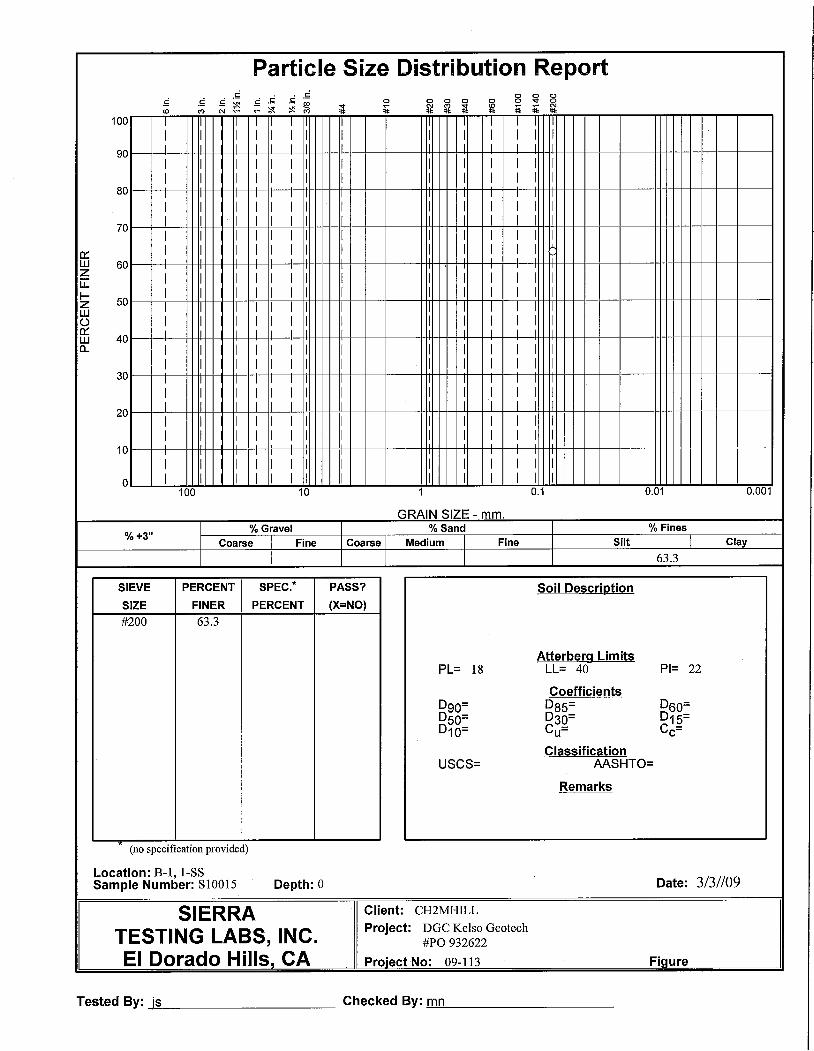
MC-2-B1-5 at 09:00WC=12.3%, P200=27.1%
SS-1-B1-0 at 08:40PP=1.25 tsf, WC =23.6%, P200=63.3%, LL=40,PI =22
25.5
21.8
20.5
SS-6-B1-15 at 09:25WC=10.1%, P200=59.9%
12.5
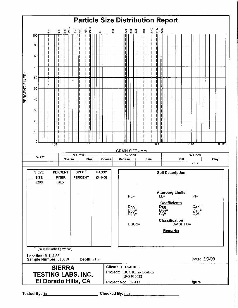
MC-7-B1-20 at 09:35WC=7.9%, P200=50.5%
8.0
1.5
25.0
21.5
20.0
15.0
11.5
10.0
16.5
SS-5-B1-11.5 at 09:20
0.0
soft drilling at 29 ft
mudstone gravel in cuttings from 27 fto to 27.5 ft
SS-9-B1-25 at 10:00
SS-8-B1-21.5 at 09:40, hard drilling from 22.5 ftto 23 ft. gravel to cobbles in cuttings. soft drillingat 23 ft.LL=NV, PI=NP
6.5
10-10-16(26)
35-38-40(78)
2-2-2(4)
39-50/6"(50/6")
37-39-48(87)
35-40-50/3"(90/9")
50/6"(50/6")
50/3"(50/3")
50/6"(50/6")
DEPTH BELOW GROUND SURFACE (ft)
5
10
15
20
25
30
DRILLING EQUIPMENT AND METHOD: CME 850 Wire Line Rig with Automatic Hammer, 8-inch Hollow Stem Auger
LOGGER : T. CHAKURIAN
B-1
ELEVATION : 144.0 ft NAD83
COMMENTS
#TYPE
SOIL BORING LOG
STANDARDPENETRATIONTEST RESULTS
PROJECT NUMBER:
LOCATION : (2111298.8 N, 6243298.0 E)
WATER LEVELS : NA
DRILLING CONTRACTOR : V and W Drilling
INTERVAL (ft)
BORING NUMBER:
START : 2/24/09 08:40
386247.01.FI
9-SS
6"-6"-6"(N)
8-SS
7-MC
6-SS
5-SS
4-SS
3-SS
2-MC
1-SS
RECOVERY (ft)
same as above
DEPTH OF CASING, DRILLING RATE,DRILLING FLUID LOSS, TESTS, AND
INSTRUMENTATION
SHEET 1 OF 2
SOIL DESCRIPTION
SOIL NAME, USCS GROUP SYMBOL, COLOR,MOISTURE CONTENT, RELATIVE DENSITY OR
CONSISTENCY, SOIL STRUCTURE, MINERALOGY
PROJECT : Mariposa Energy Project, East Alameda County, CA
END : 2/24/09 11:10
WEATHERED SANDTONE with interbeddedmudstone, light yellowish brown 10YR 6/4, finegrained sand with rounded quartz, weakly tomoderately cemented
same as above, very pale brown, 10YR 7/3
same as above. yellowish brown (10YR 5/4)
same as above
same as above
WEATHERED SANDTONE with interbeddedmudstone, yellow (10YR 7/6), fine grainedcemented, iron oxide staining, weak to moderately
LEAN CLAY (CL), very dark grayish brown, (10YR3/2), damp, medium plasticity, not dilation, weakcementation, roots, soft
WEATHERED SANDTONE, very pale brown (10YR8/3), fine to medium grained sand with roundedquartz, weakly to moderately cemented.
42.0
MC-10-B1-30 at 10:25PP=4.5 tsf (B), PP=3.25 tsf (T), WC=19.6%,UWD=101.5 pcf, ucs=2376 PSFSS-11-B1-31.5 at 10:30
SS-12-B1-35 at 10:45
MC-13-B1-40 at 11:05WC=15%, UWD=119 pcf, P200=87.7%
SS-14-B1-41.5 at 11:10, TD is 41.5 FT
32.5
10-MC
11-SS
12-SS
13-MC
14-SS
19-36-44(80)
37-50/6"(50/6")
32-50/5"(50/5")
24-37-50/2"(87/8")41.2
35.9
30.0
31.5
35.0
40.0
41.550/6"
(50/6")
DRILLING CONTRACTOR : V and W Drilling
35
40
45
50
55
60
START : 2/24/09 08:40
INTERVAL (ft)
WATER LEVELS : NA
386247.01.FI
LOCATION : (2111298.8 N, 6243298.0 E)
BORING NUMBER:
6"-6"-6"(N)
same as above. iron oxide staining
same as above. brownish yellow (10YR 6/6)
same as above. very pale brown (10YR 7/3), lessweathered, laminated bedding.
same as above. dark gray (10YR 4/1), relativelyunweathered, biotite grains visible, no laminatedbedding.same as above.
Bottom of Hole at 41.5 ft bgs -
END : 2/24/09 11:10
PROJECT : Mariposa Energy Project, East Alameda County, CA
SOIL NAME, USCS GROUP SYMBOL, COLOR,MOISTURE CONTENT, RELATIVE DENSITY OR
CONSISTENCY, SOIL STRUCTURE, MINERALOGY
SOIL DESCRIPTION
SHEET 2 OF 2
DEPTH OF CASING, DRILLING RATE,DRILLING FLUID LOSS, TESTS, AND
INSTRUMENTATION
PROJECT NUMBER:
STANDARDPENETRATIONTEST RESULTS
SOIL BORING LOG
#TYPE
COMMENTS
ELEVATION : 144.0 ft NAD83
B-1
LOGGER : T. CHAKURIAN
DRILLING EQUIPMENT AND METHOD: CME 850 Wire Line Rig with Automatic Hammer, 8-inch Hollow Stem Auger
DEPTH BELOW GROUND SURFACE (ft)
RECOVERY (ft)
MC-24-B2-6 at 09:05PP>4.5 tsf (B), PP=0.5 tsf (T), WC=14.4%,UWD=105.5 pcf, ucs=14305 psf, SwellPress.=3,650 psf, Swell=1.7%
16.5
SS-29-B2-20 at 09:40PP=2.75 tsf, P200=40.8%
SS-28-B2-16.5 at 09:30
MC-27-B2-15 at 09:25
Res= 990 ohm-cm, pH=7.62, CI=45.5,SO4=64.5
SS-25-B2-6.5 at 09:10PP>4.5 tsf, WC=11.9%, UWD=101.7 pcf,P200=71.4, EI=93, LL=41, PI=27
SS-23-B2-0 at 08:43PP=1.75 tsf
21.0
18.0
11.5
8.0
1.5
28-SS
SS-26-B2-10 at 09:20PP=2.0 tsf26-SS
25-SS
24-MC
23-SS
15.0
20.0
6-9-10(19)
8-9-10(19)
13-18-21(39)
3-3-5(8)
7-7-8(15)
27-50/6"(50/6")
10.0
6.5
5.0
0.0
10-10-15(25)
29-SS
LOGGER : T. CHAKURIANSTART : 2/25/09 08:43
5
10
15
20
25
DEPTH BELOW GROUND SURFACE (ft)
27-MC
386247.01.FI
LOCATION : (2111636.9 N, 6243245.3 E)
B-2
WATER LEVELS : ---
DRILLING CONTRACTOR : V and W Drilling
INTERVAL (ft)
BORING NUMBER:
DRILLING EQUIPMENT AND METHOD: CME 75 Wire Line Rig with Automatic Hammer, Mud Rotary with 4 5/8 drill bit
LEAN CLAY (CL). dark yellowish brown (10 YR 4/6),no gravel, very stiff
SANDY FAT CLAY (CH), dark yellowish brown 10YR 4/4; high plasticity, not dilatancy, strongcementation, fine gravel, fine sand, hard clay
LEAN CLAY (CL), very dark grayish brown (10YR3/2), damp, medium plasticity, no dilatancy, weakcementation, roots, firm
WEATHERED SANDSTONE with interbeddedmudstone, yellowish brown 10YR 5/4, fine grainedsand with rounded quartz, weak to moderatelycemented, iron oxidesame as above, brown 10YR 6/4, fine to mediumgrained sand
ELEVATION : 119.0 ft NAD83
COMMENTS
#TYPE
SOIL BORING LOG
STANDARDPENETRATIONTEST RESULTS
PROJECT NUMBER:
WEATHERED MUDSTONE, pale brown 10YR 6/3.weakly cemented
RECOVERY (ft) DEPTH OF CASING, DRILLING RATE,DRILLING FLUID LOSS, TESTS, AND
INSTRUMENTATION
SHEET 1 OF 5
SOIL DESCRIPTION
SOIL NAME, USCS GROUP SYMBOL, COLOR,MOISTURE CONTENT, RELATIVE DENSITY OR
CONSISTENCY, SOIL STRUCTURE, MINERALOGY
PROJECT : Mariposa Energy Project, East Alameda County, CA
END : 2/25/09 17:30
same as above, yellow 10YR 7/6, fine to coarsesand, fine subrounded gravel
6"-6"-6"(N)

MC-30-B2-25 at 09:55
SS-31-B2-26.5 at 10:00PP=3.5 tsf
SS-32-B2-30 at 10:30PP=3.5 tsf
MC-33-B2-35 at 10:45
SS-34-B2-36.5 at 10:50.hard drilling at 35 ft, unable to drill further withmud rotary, switch to rock coring. loggingcontinues on rock core log.
33.4
31.0
30-MC
31-SS
32-SS
33-MC
34-SS
21-28-34(62)
12-16-20(36)
29-50/6"(50/6")
50/5"(50/5")
34.8
25.0
26.5
30.0
33.0
34.5
28.0
50/3"(50/3")
INTERVAL (ft)
30
35
40
45
50
START : 2/25/09 08:43
BORING NUMBER:
DRILLING CONTRACTOR : V and W Drilling
WATER LEVELS : ---
386247.01.FI
LOCATION : (2111636.9 N, 6243245.3 E)
RECOVERY (ft)
same as above, gray 10YR 5/1, relativelyunweathered, biotite grains visible, laminatedbedding, fine to medium grained sand
same as above, dark gray 10YR 4/1
same as above, moderately to strongly cemented
same as above, weak to moderately cemented
same as aboveBegin Rock Coring at 34.8 ft below ground surfaceSee the next sheet for the rock core log
END : 2/25/09 17:30
PROJECT : Mariposa Energy Project, East Alameda County, CA
SOIL NAME, USCS GROUP SYMBOL, COLOR,MOISTURE CONTENT, RELATIVE DENSITY OR
CONSISTENCY, SOIL STRUCTURE, MINERALOGY
SOIL DESCRIPTION
SHEET 2 OF 5
COMMENTSDEPTH BELOW GROUND SURFACE (ft)
DRILLING EQUIPMENT AND METHOD: CME 75 Wire Line Rig with Automatic Hammer, Mud Rotary with 4 5/8 drill bit
LOGGER : T. CHAKURIAN
DEPTH OF CASING, DRILLING RATE,DRILLING FLUID LOSS, TESTS, AND
INSTRUMENTATION
ELEVATION : 119.0 ft NAD83
#TYPE
SOIL BORING LOG
STANDARDPENETRATIONTEST RESULTS
PROJECT NUMBER:
6"-6"-6"(N)
B-2

2
2
0
0
>10
1
>10
3
1
1
1
3
>10
>10
>10
1
1
>10
1
SY
MB
OLI
C L
OG
34.8' ANDESITE DIKE, gray (10YR6/1), crystalline, aphanitic, finegrained quartz, biotite, plagioclase,unaltered, veinlets, localizedhydrothermal attenuation
0
0
2
1
1
1
58.7' - 59.7' MUDSTONE, black(10YR 2/1), moderately cemented.
55' massive bedding54.7' - 55' laminated bedding
same as above
39.2' SANDSTONE with interbeddedmudstone, dark gray (10YR 4/1),fine grained sand with biotite androunded quartz, moderatelycemented
37.65' ANDESITE DIKE, gray (10YR6/1), crystalline, fine to coarsegrained quartz, biotite andplagioclase unaltered
35.8' SANDSTONE with interbeddedmudstone, dark gray (10YR 4/1),fine grained sand with biotite androunded quartz, moderatelycemented.
35.65' - 35.8' ANDESITE DIKE, gray(10YR 6/1), crystalline, aphanitic,fine grained quartz, biotite andplagioclase unaltered
35.2' SANDSTONE with interbeddedmudstone, dark gray, (10YR 4/6),fine grained sand with roundedquartz and biotite, moderatelycemented
49' - 49.3' highly fractured
55.0
50.0
45.0
40.0
35.034.8
54.1' - 54.7' highly fractured
37.65' - 40' highly fractured
35.7' - 35.8' highly fractured35.2' - 35.3' highly fractured
ELEVATION : 119.0 ft NAD83
END : 2/25/09 17:30START : 2/25/09 08:43
LOCATION : (2111636.9 N, 6243245.3 E)FR
ACTU
RES
PE
R F
OO
T
R Q
D (%
)
ORIENTATION :CORING METHOD AND EQUIPMENT : CME 75 Wire Line Rig with Automatic Hammer, Mud Rotary with 4 5/8 drill bit
CO
RE
RU
N,
LEN
GTH
, AN
DR
EC
OV
ER
Y (%
)
SIZE AND DEPTH OF CASING,FLUID LOSS, CORING RATE AND
SMOOTHNESS, CAVING RODDROPS, TEST RESULTS, ETC.
B-2386247.01.FI
WATER LEVELS : ---
SHEET 3 OF 5
PROJECT : Mariposa Energy Project, East Alameda County, CA
COMMENTS
40
45
50
55
BORING NUMBER:
LOGGER : T. CHAKURIAN
ROCK TYPE, COLOR,MINERALOGY, TEXTURE,
WEATHERING, HARDNESS,AND ROCK MASS
CHARACTERISTICS
DISCONTINUITIES
DESCRIPTION
DEPTH, TYPE, ORIENTATION, ROUGHNESS,PLANARITY, INFILLING MATERIAL AND
THICKNESS, SURFACE STAINING, AND TIGHTNESSDE
PTH
BE
LOW
SU
RFA
CE
(ft)
PROJECT NUMBER:
50
LITHOLOGY
83
97
83
P200=73.5%, LL=52,PI=26, UCS=3727 psf
P200=69.6%
encounter core at 34.8 ft
78
ROCK CORE LOG
DRILLING CONTRACTOR : V and W Drilling
84.0
79.0
74.0
69.0
64.0
4-HQ5 ft
100%
2-HQ5 ft
80%
5-HQ5 ft
100%
6-HQ5 ft
91%
3-HQ5 ft
100%

NR
0
5
2
NR
2
3
2
3
1
1
>10
71
6
SY
MB
OLI
C L
OG
59.7' SANDSTONE with interbeddedmudstone, dark gray (10YR 4/1),fine grained sand with biotite androunded quartz, moderatelycemented.
2
4
60.0
75.8' SANDSTONE with interbeddedmudstone, dark gray (10YR 4/1),fine grained sand with biotite androunded quartz, moderately tostrongly cemented
same as above
70' SANDSTONE, dark gray (10YR4/1), fine to medium grained sandwith biotite and rounded quartz.moderately to strongly cemented
64.65' strongly cemented
62.6' SANDSTONE with interbeddedmudstone, dark gray (10YR 4/1),fine grained sand with biotite, androunded quartz, moderatelycemented
61.3' MUDSTONE, black (10YR2/1), moderately cemented
same as above
NR
1
2
1
1
2
1
1
59.85' fracture, 45 degrees, planar andsmooth
61.5' fracture, 43 degrees, planar, rough
80.0
75.0
70.0
65.0
85
2
R Q
D (%
)
FRAC
TUR
ESP
ER
FO
OT
END : 2/25/09 17:30LITHOLOGY
DESCRIPTION
LOCATION : (2111636.9 N, 6243245.3 E)
ORIENTATION :
CO
RE
RU
N,
LEN
GTH
, AN
DR
EC
OV
ER
Y (%
)
68
START : 2/25/09 08:43
PROJECT : Mariposa Energy Project, East Alameda County, CA
DE
PTH
BE
LOW
SU
RFA
CE
(ft)
DEPTH, TYPE, ORIENTATION, ROUGHNESS,PLANARITY, INFILLING MATERIAL AND
THICKNESS, SURFACE STAINING, AND TIGHTNESS
WATER LEVELS : ---
65
70
75
80
BORING NUMBER:
LOGGER : T. CHAKURIAN
ROCK TYPE, COLOR,MINERALOGY, TEXTURE,
WEATHERING, HARDNESS,AND ROCK MASS
CHARACTERISTICS
DISCONTINUITIES
SHEET 4 OF 5
UCS=28717 psf,WC=11.4%, UWD=1248pcf
SIZE AND DEPTH OF CASING,FLUID LOSS, CORING RATE AND
SMOOTHNESS, CAVING RODDROPS, TEST RESULTS, ETC.
36
CORING METHOD AND EQUIPMENT : CME 75 Wire Line Rig with Automatic Hammer, Mud Rotary with 4 5/8 drill bit
59.0
54.0
49.0
44.0
39.0
rotten egg odor (H2S)
driller identified intervalfrom 69 ft-70 ft as softmaterial. no recovery.
rotten egg odor (H2S)
rotten egg odor (H2S)
9
COMMENTS
B-2386247.01.FI
ELEVATION : 119.0 ft NAD83
PROJECT NUMBER:
DRILLING CONTRACTOR : V and W Drilling
ROCK CORE LOG
7-HQ5 ft
91%
8-HQ5 ft
80%
9-HQ5 ft
100%
10-HQ5 ft
97%
11-HQ5 ft
48%

2
90.0
1
>10
7
0
0
0
0
1
2
1
100.0
>10
SY
MB
OLI
C L
OG
84.8 SANDSTONE, dark gray (10YR4/1), fine to medium grained sandwith biotite and rounded quartz,moderately cemented.
3
85.0
1
1
94.45' SANDSTONE interbeddedwith mudstone, dark gray (10 YR4/1), fine grained sand with biotiteand rounded quartz, moderatelycemented
95.0
Bottom of Hole at 100.0 ft bgs -
93.95' - 94.45' ANDESITE DIKE,gray (10YR 6/1), crystalline,aphanitic, fine grained, quartz,biotite, plagioclase unaltered
93.35' - 93.95' SANDSTONEinterbedded with mudstone, darkgray (10YR 4/1), fine grained sandwith biotite, and rounded quartz,strongly cemented, indurated
93' - 93.35' ANDESITE DIKE, gray(10YR 6/1), crystalline, aphanitic,fine grained quartz, biotite,plagioclase, unaltered
92.45' - 93' SANDSTONEinterbedded with mudstone, darkgray (10YR 4/1), fine grained sandwith biotite and rounded quartz,moderately cemented
92.2' 92.45' ANDESITE DIKE, gray(10YR 6/1), crystalline, aphanitic,fine grained quartz, biotite,plagioclase, unaltered
90.3' SANDSTONE, dark gray(10YR 4/1), fine grained sand withbiotite, and rounded quartz,moderately cemented
87.2 SANDSTONE with interbeddedmudstone, dark gray (10YR 4/1),fine grained sand with biotite, androunded quartz, moderatelycemented
98.41' - 98.5' highly fractured
94.95' fracture, 50 degrees, planar andsmooth
93.25' - 93.35' highly fractured93' fracture, 60 degrees, planar and smooth
89.9' - 90.3' highly fractured
85.7, - 85.9' highly fractured
88.7' - 89.45' highly fractured
START : 2/25/09 08:43
CORING METHOD AND EQUIPMENT : CME 75 Wire Line Rig with Automatic Hammer, Mud Rotary with 4 5/8 drill bit
R Q
D (%
)
FRAC
TUR
ESP
ER
FO
OT
DESCRIPTION
END : 2/25/09 17:30DISCONTINUITIES
84
ORIENTATION :
DE
PTH
BE
LOW
SU
RFA
CE
(ft)
DEPTH, TYPE, ORIENTATION, ROUGHNESS,PLANARITY, INFILLING MATERIAL AND
THICKNESS, SURFACE STAINING, AND TIGHTNESS
SHEET 5 OF 5
PROJECT : Mariposa Energy Project, East Alameda County, CA
WATER LEVELS : ---
90
95
100
105
BORING NUMBER:
LOGGER : T. CHAKURIAN
ROCK TYPE, COLOR,MINERALOGY, TEXTURE,
WEATHERING, HARDNESS,AND ROCK MASS
CHARACTERISTICS
ROCK CORE LOGC
OR
E R
UN
,LE
NG
TH, A
ND
RE
CO
VE
RY
(%)
WC=0.6%, UWD=166.8pcf, UCS=1,498,320 psf
LOCATION : (2111636.9 N, 6243245.3 E)
DRILLING CONTRACTOR : V and W Drilling
34.0
29.0
24.0
19.0
14.0
total depth at 100 feet.
74
LITHOLOGY
SIZE AND DEPTH OF CASING,FLUID LOSS, CORING RATE AND
SMOOTHNESS, CAVING RODDROPS, TEST RESULTS, ETC.
COMMENTS
B-2386247.01.FI
ELEVATION : 119.0 ft NAD83
80
PROJECT NUMBER:
12-HQ5 ft
100%
13-HQ5 ft
98%
14-HQ5 ft
96%
16-MC
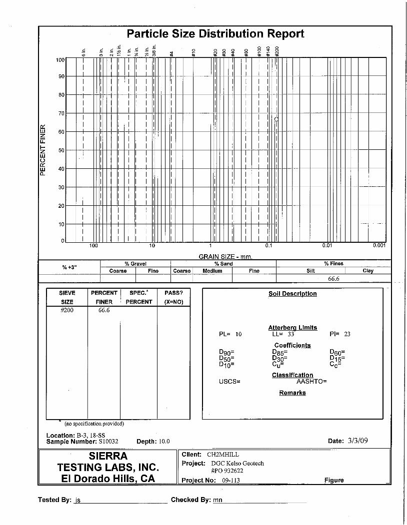
SS-18-B3-15 at 12:15PP=2.75 tsf, WC=16.5%, P200=66.6%, LL=33,PI=23
MC-16-B3-5 at 12:07PP=4.25 tsf (B), PP=4.5 tsf (T), WC=10.7%,UWD=107.7 pcf, EI=143, ucs=4403 psf
15-SS
SS-15-B3-0 at 11:57PP=1.5 tsf, WC=21.8%, P200=81.6%, LL=38,PI=28
17-SS
18-SS
LEAN CLAY (CL), very dark grayish brown (10YR3/2), damp, medium plasticity, no dilatancy, weakcementation, stiff.
same as above, dark yellowish brown (10 YR 4/4),very stiff.
2-3-7(10)
6-10-15(25)
8-12-12(24)
6-7-10(17)
SS-17-B3-6.5 at 12:10PP=2.25 tsf, Swell Press.=920 psf, Swell=0.1%
END : 2/24/09 16:30
0.0
5.0
6.5
10.0
1.5
8.0
11.5
WATER LEVELS : NA
5
10
15
START : 2/24/09 13:15
BORING NUMBER:
same as above, brown (10YR 4/3), very stiff.
DRILLING CONTRACTOR : V and W Drilling
386247.01.FI
LOCATION : (2112118.7 N, 6243314.4 E)
INTERVAL (ft)
COMMENTS
RECOVERY (ft)
PROJECT : Mariposa Energy Project, East Alameda County, CA
SOIL NAME, USCS GROUP SYMBOL, COLOR,MOISTURE CONTENT, RELATIVE DENSITY OR
CONSISTENCY, SOIL STRUCTURE, MINERALOGY
SOIL DESCRIPTION
SHEET 1 OF 3
DEPTH OF CASING, DRILLING RATE,DRILLING FLUID LOSS, TESTS, AND
INSTRUMENTATION6"-6"-6"(N)
PROJECT NUMBER:
STANDARDPENETRATIONTEST RESULTS
#TYPE
ELEVATION : 112.0 ft NAD83
B-3
LOGGER : T. CHAKURIAN
DRILLING EQUIPMENT AND METHOD: CME 75 Wire Line Rig with Automatic Hammer, 8-inch Hollow Stem Auger
DEPTH BELOW GROUND SURFACE (ft)
same as above.
SOIL BORING LOG

19-MC
20-SS
21-SS
SOIL NAME, USCS GROUP SYMBOL, COLOR,MOISTURE CONTENT, RELATIVE DENSITY OR
CONSISTENCY, SOIL STRUCTURE, MINERALOGY
SS-21-B3-20 at 12:30
same as above. yellowish brown (10YR 5/4), verystiff
CLAYEY SAND (SC), dark yellowish brown (10YR4/6), wet, weak to moderate cementation, fine tomedium grained sand, clay, rounded, well graded,dense
GRAVELLY LEAN CLAY (CL), brown (10YR 5/3),wet, medium plasticity, no dilatancy, weakcementation, subrounded gravel, fine to coarsesand, hard.
Begin Rock Coring at 23.0 ft below ground surfaceSee the next sheet for the rock core log
END : 2/24/09 16:30
12-12-15(27)
16-18-20(38)
25-37-44(81)
Hard drilling from 22 ft to 23 ft. likely bedrock.drill bit broke at 23 ft. borehole was abandoned.total depth is 23 ft.
15.0
16.5
20.0
23.0
18.0
21.5
MC-19-B3-15 at 12:20PP=3.0 tsf (B). PP=4.25 tsf (T)
SS-20-B3-16.5 at 12:25. groundwater at 16.5FT.
SOIL DESCRIPTION
20
25
30
START : 2/24/09 13:15
BORING NUMBER:
INTERVAL (ft)
PROJECT : Mariposa Energy Project, East Alameda County, CA
WATER LEVELS : NA
386247.01.FI
LOCATION : (2112118.7 N, 6243314.4 E)
DRILLING CONTRACTOR : V and W Drilling
LOGGER : T. CHAKURIAN
SHEET 2 OF 3
DEPTH OF CASING, DRILLING RATE,DRILLING FLUID LOSS, TESTS, AND
INSTRUMENTATION6"-6"-6"(N)
PROJECT NUMBER:
STANDARDPENETRATIONTEST RESULTS
SOIL BORING LOG
#TYPE
COMMENTS
B-3
DRILLING EQUIPMENT AND METHOD: CME 75 Wire Line Rig with Automatic Hammer, 8-inch Hollow Stem Auger
DEPTH BELOW GROUND SURFACE (ft)
RECOVERY (ft)
ELEVATION : 112.0 ft NAD83

WC=38.4%, UWD=83.6pcf, LL=81, PI=54,UCS=3496 psf,P200=62.7, P40=95.2%
0
16
90
DRILLING CONTRACTOR : V and W Drilling
Gravel encountered at 23ft appears to beassociated with theconglomerate at 29 ftWC=35%, UWD=87.8 pcf,UCS=4508 psf
1
Tan Sample (34 ft)WC=31.3%, UWD=86.6pcf, LL=92, PI=63,UCS=3020 psf,P200=69.6%, P40=96.8%Black Sample (34 ft)WC=38.7%, UWD=81.8pcf, LL=83, PI=36,UCS=4933 psf,P200=73.8%, P40=96%Driller notes that clayclogged the rock coringsystem at 35 feet. drillerpulls casing and boringcollapses. total depth at 35feet.
29' WEATHEREDCONGLOMORATE, very pale brown(10YR 8/2), coarse grained sand tocoarse gravel with subangular torounded fragments of red and greenchert, SANDSTONE and quartzite,well cemented.
87.0
82.0
77.0
SY
MB
OLI
C L
OG
25.0
29.5' WEATHERED SANDSTONEwith interbedded mudstone,yellowish brown (10YR 5/4), fine tomedium grained sand, rounded,clay, weakly cemented
33' SANDSTONE is relativelyunweathered, gray (10YR 5/1).
Bottom of Hole at 35.0 ft bgs -
fracture, 70 degrees, rough undulatingsurface
fracture 80 degrees, smooth planar surface
23.0
30.0
35.0
1
1
1
2
2
ROCK CORE LOG
25
30
35
FRAC
TUR
ESP
ER
FO
OT
R Q
D (%
)
DEPTH, TYPE, ORIENTATION, ROUGHNESS,PLANARITY, INFILLING MATERIAL AND
THICKNESS, SURFACE STAINING, AND TIGHTNESS
DESCRIPTION
DISCONTINUITIES
ROCK TYPE, COLOR,MINERALOGY, TEXTURE,
WEATHERING, HARDNESS,AND ROCK MASS
CHARACTERISTICS
BORING NUMBER:
END : 2/24/09 16:30WATER LEVELS : NA
PROJECT : Mariposa Energy Project, East Alameda County, CA
DE
PTH
BE
LOW
SU
RFA
CE
(ft)
SHEET 3 OF 3
LOGGER : T. CHAKURIAN
386247.01.FI
ELEVATION : 112.0 ft NAD83
START : 2/24/09 13:15
B-3
SIZE AND DEPTH OF CASING,FLUID LOSS, CORING RATE AND
SMOOTHNESS, CAVING RODDROPS, TEST RESULTS, ETC.
LITHOLOGY
CO
RE
RU
N,
LEN
GTH
, AN
DR
EC
OV
ER
Y (%
)
CORING METHOD AND EQUIPMENT : CME 75 Wire Line Rig with Automatic Hammer
LOCATION : (2112118.7 N, 6243314.4 E)
COMMENTS
PROJECT NUMBER:
ORIENTATION :
3-HQ5 ft
97%
2-HQ5 ft
18%
1-HQ2 ft0%

#TYPE
Depth below surface values are approximatedue to method of excavation.
Composite Sample 1: Res=1,210 ohm-cm,CI=75 ppm, SO4=3 ppm, R-value at 300 psi=8,Expansive index at 300 psi=22 psf
Composite Sample 2: Res=1,000 ohm-cm,CI=66 ppm, SO4=306 ppm, R-value at 300psi=22, Expansive index at 300 psi=62 psf
TD at 10 ft at 12:05 pm. reached limit ofexcavator arm
LEAN CLAY (CL), dark brown, moist, low plasticity, soft, clay with silt[topsoil]
Composite Sample1 consists of TP-1-1, TP-1-2,TP-2-1, TP-2-2, TP-3-1, TP-4-1, TP-4-2, TP-5-1,TP-5-2. Composite Sample 2 consists of TP-1-3, TP-1-4, TP-2-3, TP-3-2, TP-4-3, TP-5-3, TP-5-4, TP-6-3
SANDY SILT (ML), light brown, dry, low plasticityl, medium sandy silt
SAND (SP), light brown, dry, poorly graded, medium dense, fine sandwith occassional calcareous nodules [WEATHERED SANDTONE]
WEATHERED SANDTONE orangish brown, dry, poorly graded,medium dense fine SAND (SP)
Bottom of Hole at 10.0 ft bgs -
PROJECT NUMBER:
1-BU
2-BU
3-BU
4-BU
PROJECT: Mariposa Energy Project, East Alameda County, CA
WATER LEVELS: not encountered DEPTH:
TEST PIT NUMBER:
ELEVATION: 136.0 ft NAD83
LOGGER: J. DEAN
LOGGRAPHIC
DEPTH OF CASING, DRILLING RATE,DRILLING FLUID LOSS, TESTS, AND
INSTRUMENTATION
1
2
3
4
5
6
7
8
9
10
11
12
13
14
15
16
TP-1 SHEET 1 OF 1
TEST PIT LOG
CONTRACTOR: Diamond D Engineering
LOCATION: (2111309.8 N, 6243238.4 E)
DATE EXCAVATED: 02/19/2009 11:25:00 AM
386247.01.FI
BELOWDEPTH
SURFACE
SOIL DESCRIPTION COMMENTS
SOIL NAME, USCS GROUP SYMBOL, COLOR,MOISTURE CONTENT, RELATIVE DENSITY OR
CONSISTENCY, SOIL STRUCTURE, MINERALOGY
LENGTH: WIDTH:
EXCAVATION EQUIPMENT: PC-35 Excavator w/ 30" Bucket

Depth below surface values are approximatedue to method of excavation.
Composite Sample 1: (See TP-1)
Composite Sample 2: (See TP-1)
from surface, can see bedding dipping towardthe east ~35 degrees
TD at 10 ft at 12:05 pm. reached limit ofexcavator arm
1
2
3
4
5
6
7
8
9
10
11
12
13
14
15
16
LEAN CLAY (CL), dark brown, moist, soft, low plasticity clay [topsoil]
PROJECT NUMBER:
#TYPE
LEAN CLAY (CL), dark brown, moist, soft, low plasticity, clay withsome silt and calcareous patches
WEATHERED SANDTONE, light brown, moist, poorly graded,medium dense, fine sand.
WEATHERED SANDTONE, light brown, moist, poorly-graded,medium dense sand with larger fragments of cemented rock
Bottom of Hole at 10.0 ft bgs -
1-BU
2-BU
3-BU
TEST PIT NUMBER:
LOCATION: (2111370.4 N, 6243008.8 E)
DEPTH:
DATE EXCAVATED: 02/19/2009 10:40:00 AM
PROJECT: Mariposa Energy Project, East Alameda County, CA
LOGGER: J. DEAN
LOGGRAPHIC
DEPTH OF CASING, DRILLING RATE,DRILLING FLUID LOSS, TESTS, AND
INSTRUMENTATION
TEST PIT LOG
CONTRACTOR: Diamond D Engineering
DEPTH
TP-2
BELOW
WATER LEVELS: not encountered
386247.01.FI SHEET 1 OF 1
SOIL DESCRIPTION
SURFACE
COMMENTS
SOIL NAME, USCS GROUP SYMBOL, COLOR,MOISTURE CONTENT, RELATIVE DENSITY OR
CONSISTENCY, SOIL STRUCTURE, MINERALOGY
LENGTH: WIDTH:
EXCAVATION EQUIPMENT: PC-35 Excavator w/ 30" Bucket
ELEVATION: 132.0 ft NAD83
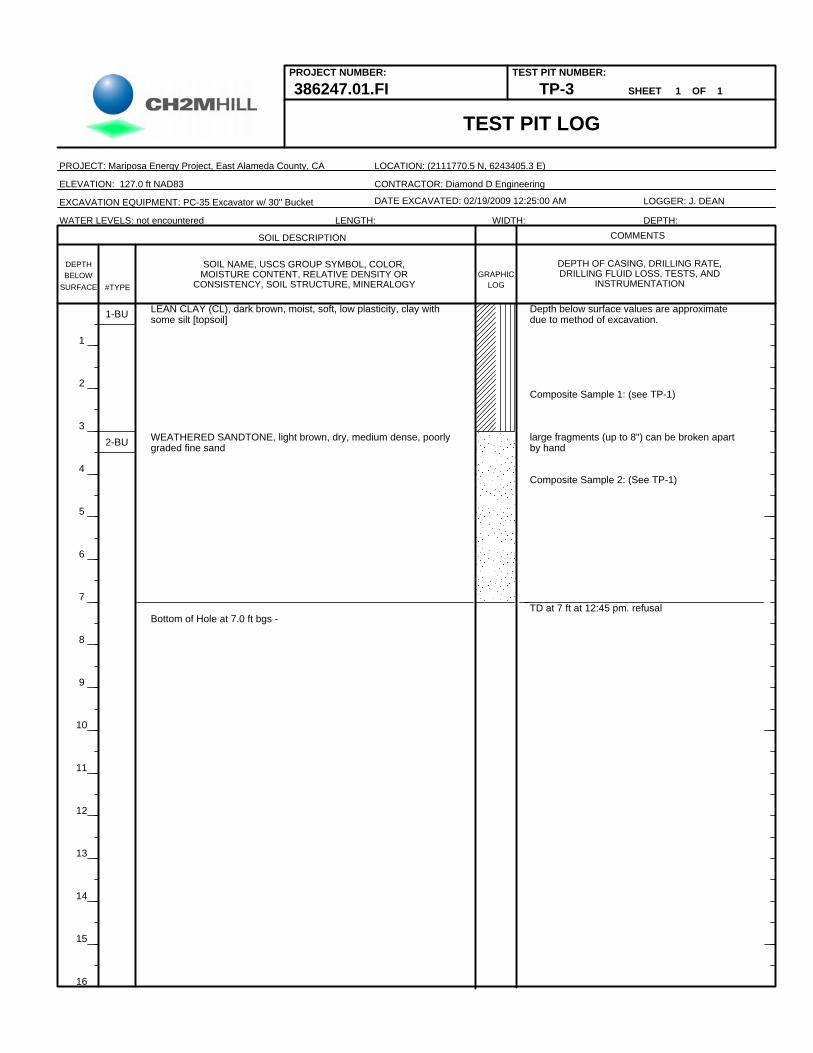
386247.01.FI
large fragments (up to 8") can be broken apartby hand
PROJECT NUMBER: TEST PIT NUMBER:
1
2
3
4
5
6
7
8
9
10
11
12
13
14
15
16
DATE EXCAVATED: 02/19/2009 12:25:00 AM
LEAN CLAY (CL), dark brown, moist, soft, low plasticity, clay withsome silt [topsoil]
WEATHERED SANDTONE, light brown, dry, medium dense, poorlygraded fine sand
Bottom of Hole at 7.0 ft bgs -TD at 7 ft at 12:45 pm. refusal
2-BU
Composite Sample 2: (See TP-1)
Depth below surface values are approximatedue to method of excavation.
Composite Sample 1: (see TP-1)
TP-3
1-BU
WATER LEVELS: not encountered
#TYPE
LOCATION: (2111770.5 N, 6243405.3 E)
LOGGER: J. DEAN
LOGGRAPHIC
DEPTH OF CASING, DRILLING RATE,DRILLING FLUID LOSS, TESTS, AND
INSTRUMENTATION
COMMENTS
SHEET 1 OF 1
TEST PIT LOG
CONTRACTOR: Diamond D Engineering
DEPTHBELOW
SURFACE
DEPTH:
SOIL DESCRIPTION
PROJECT: Mariposa Energy Project, East Alameda County, CA
SOIL NAME, USCS GROUP SYMBOL, COLOR,MOISTURE CONTENT, RELATIVE DENSITY OR
CONSISTENCY, SOIL STRUCTURE, MINERALOGY
LENGTH: WIDTH:
EXCAVATION EQUIPMENT: PC-35 Excavator w/ 30" Bucket
ELEVATION: 127.0 ft NAD83

Composite Sample 1: (see TP-1)
Composite Sample 2: (See TP-1)
TD at 9.5 ft at 10:30 am. reached limit ofexcavator arm
#TYPE
PROJECT NUMBER:
LEAN CLAY (CL), dark brown, moist, soft, low plasticity clay withsome silt and rootlets [topsoil]1
2
3
4
5
6
7
8
9
10
11
12
13
14
15
16
1-BU
LEAN CLAY (CL), dark brown, moist, low plasticity, medium clay withsome silt
WEATHERED SANDTONE, light brown, moist, poorly graded,medium dense, fine sand becomes more yellowish brown with depth
Bottom of Hole at 9.5 ft bgs -
Depth below surface values are approximatedue to method of excavation.
2-BU
3-BU
DATE EXCAVATED: 02/19/2009 10:00:00 AM
LOCATION: (2111440.5 N, 6243125.8 E)
TEST PIT NUMBER:
DEPTH:
PROJECT: Mariposa Energy Project, East Alameda County, CA
LOGGER: J. DEAN
LOGGRAPHIC
DEPTH OF CASING, DRILLING RATE,DRILLING FLUID LOSS, TESTS, AND
INSTRUMENTATION
SOIL DESCRIPTION
TEST PIT LOG
CONTRACTOR: Diamond D Engineering
DEPTH
TP-4
BELOW
WATER LEVELS: not encountered
SHEET 1 OF 1
ELEVATION: 123.0 ft NAD83
SURFACE
COMMENTS
SOIL NAME, USCS GROUP SYMBOL, COLOR,MOISTURE CONTENT, RELATIVE DENSITY OR
CONSISTENCY, SOIL STRUCTURE, MINERALOGY
LENGTH: WIDTH:
EXCAVATION EQUIPMENT: PC-35 Excavator w/ 30" Bucket
386247.01.FI

Depth below surface values are approximatedue to method of excavation.
Composite Sample 1: (see TP-1)
Composite Sample 2: (See TP-1)
at 9 feet, became slightly harder to excavate
TD at 10 ft at 9:45 am. reached limit ofexcavator arm
#TYPE
LEAN CLAY (CL), dark brown, moist, low plasticity, soft clay withsome silt. [topsoil] contains rootlets
PROJECT NUMBER:
2-BU LEAN CLAY (CL),,dark brown, moist, low plasticity, medium clay withsome siltt, increased white calcareous nodules with depth.
WEATHERED SANDTONE, light brown, moist, poorly graded,medium dense fine SAND (SP) with some clay
Bottom of Hole at 10.0 ft bgs -
1-BU
3-BU
4-BU
TEST PIT NUMBER:
PROJECT: Mariposa Energy Project, East Alameda County, CA
WATER LEVELS: not encountered DEPTH:
1
2
3
4
5
6
7
8
9
10
11
12
13
14
15
16
ELEVATION: 117.0 ft NAD83
LOGGER: J. DEAN
LOGGRAPHIC
DEPTH OF CASING, DRILLING RATE,DRILLING FLUID LOSS, TESTS, AND
INSTRUMENTATIONSURFACE
TP-5 SHEET 1 OF 1
TEST PIT LOG
CONTRACTOR: Diamond D Engineering
LOCATION: (2111941.2 N, 6243230.3 E)
DATE EXCAVATED: 02/19/2009 9:00:00 AM
386247.01.FI
BELOWDEPTH
SOIL DESCRIPTION COMMENTS
SOIL NAME, USCS GROUP SYMBOL, COLOR,MOISTURE CONTENT, RELATIVE DENSITY OR
CONSISTENCY, SOIL STRUCTURE, MINERALOGY
LENGTH: WIDTH:
EXCAVATION EQUIPMENT: PC-35 Excavator w/ 30" Bucket

Composite Sample 2: (See TP-1)
TD at 10ft at 13:20 due to limit of excavator arm
#TYPE
PROJECT NUMBER: TEST PIT NUMBER:
LEAN CLAY (CL),, dark brown, moist, soft, low plasticity, clay withsome silt [topsoil]
DATE EXCAVATED: 02/19/2009 1:00:00 PM
1-BU
LEAN CLAY (CL), medium brown, dry, medium, low plasticity, Lclaywith some silt.
WEATHERED SANDTONE, light brown, dry, medium dense, poorlygraded fine sand,
Bottom of Hole at 10.0 ft bgs -
Depth below surface values are approximatedue to method of excavation.
2-BU
3-BU
WATER LEVELS: not encountered
1
2
3
4
5
6
7
8
9
10
11
12
13
14
15
16
386247.01.FI
LOCATION: (2111966.5 N, 6243410.4 E)
LOGGER: J. DEAN
LOGGRAPHIC
DEPTH OF CASING, DRILLING RATE,DRILLING FLUID LOSS, TESTS, AND
INSTRUMENTATION
COMMENTS
CONTRACTOR: Diamond D Engineering
DEPTHBELOW
SHEET 1 OF 1
SURFACE
DEPTH:
TEST PIT LOG
PROJECT: Mariposa Energy Project, East Alameda County, CA
SOIL DESCRIPTION
SOIL NAME, USCS GROUP SYMBOL, COLOR,MOISTURE CONTENT, RELATIVE DENSITY OR
CONSISTENCY, SOIL STRUCTURE, MINERALOGY
LENGTH: WIDTH:
EXCAVATION EQUIPMENT: PC-35 Excavator w/ 30" Bucket
ELEVATION: 117.0 ft NAD83
TP-6

ATTACHMENT 2
Laboratory Test Results