Embed Size (px)
Citation preview
ALASKA PIPELINE PROJECT DRAFT RESOURCE REPORT 1
GENERAL PROJECT DESCRIPTION APPENDIX 1H
USAG-UR-SGREG-000002DECEMBER 2011
REVISION 0
FERC Docket No. PF09-11-000
APPENDIX 1H RATIONALE FOR THE WIDTH OF THE CONSTRUCTION AND PERMANENT RIGHT-OF-WAY
DRAFT
ALASKA PIPELINE PROJECT DRAFT RESOURCE REPORT 1
GENERAL PROJECT DESCRIPTION APPENDIX 1H
USAG-UR-SGREG-000002DECEMBER 2011
REVISION 0
FERC Docket No. PF09-11-000 PAGE 1H-1
CONSTRUCTION RIGHT-OF-WAY RATIONALE
The proposed project will be constructed under various seasonal and construction conditions. The proposed construction right-of-way widths for the Project are the minimum widths required to effectively, efficiently and safely construct Alaska Pipeline Project (APP) pipelines. Construction right-of-way widths will be further refined as the route centerline is updated and established, additional geotechnical data is developed, and the construction execution plan is finalized. The currently proposed cases represent the majority of expected construction scenarios. It is also expected that the final centerline will pass through some restricted areas requiring reduced construction right-of-way widths.
Listed below are the four construction scenarios for the proposed project:
Winter construction - south of the tree line;
Summer construction - south of the tree line;
Winter construction - north of the tree line; and
Saturated wetland crossings winter and summer construction.
The construction right-of-way for the Project is divided into four main areas and a number of subareas, depending on the specific construction situation.
1) Spoil area:
Topsoil and loose surface material storage area;
Cut slope;
Bypass lane; and
Trench spoil.
2) Trench area:
Trench excavation and ripping.
3) Work area:
Pipe make-up; and
Primary work area.
4) Travel area:
Secondary work lane;
Travel lane;
Safety buffer; and
Fill slope.
Each configuration and their areas are described in detail below.
DRAFT

ALASKA PIPELINE PROJECT DRAFT RESOURCE REPORT 1
GENERAL PROJECT DESCRIPTION APPENDIX 1H
USAG-UR-SGREG-000002DECEMBER 2011
REVISION 0
FERC Docket No. PF09-11-000 PAGE 1H-2
H-1 WINTER CONSTRUCTION - SOUTH OF THE TREE LINE (WIDTH: 160 FEET)
The right-of-way for winter construction south of the tree line will be made up of four areas: Spoil area (60 feet), trench area (20 feet), work area (40 feet), and travel area (40 feet) (refer to Figure H-1). Justifications for the four areas are discussed below.
FIGURE H-1. Right-of-way Configuration for Winter Construction - South of the Tree Line
H-1.1 SPOIL AREA (WIDTH: 60 FEET)
The spoil storage area will comprise a 15-foot-wide area for loose surface materials, 15-foot-widebypass lane and a 30-foot-wide area for trench spoil.
H-1.1.1 Bypass Lane and Loose Surface Material Storage (WIDTH: 30 FEET)
Any snow and loose surface materials will be bladed over the proposed trench location before construction to form an insulating trench line roach (mound). The base of the insulating roach will be approximately 20 feet in width. Just prior to trench excavation, this material will be bladed to the storage sides.
In the spoil area, the loose surface material will be mounded up 15 feet from the bottom of the spoil storage pile to make way for a bypass lane used to “leap frog” trenching equipment on the work side of the right-of-way alongside of the spoil pile. Additionally, should the pipe be welded in strings at the time of trench excavation, it is difficult to move trenching equipment to the work side of the right-of-way with the pipe strings in place, additional width is required.
During reclamation, the stored surface material will be re-spread over the finished graded slopes and workspaces.
H-1.1.2 Spoil Storage (WIDTH: 30 FEET)
The volume of trench spoil generated is dependent on the type of in-situ material in which the trench is excavated, the shape of the trench, and the type of equipment used to excavate the trench. The spoil generated in surficial materials, such as glacial till, will bulk (i.e., expand from volume of in-situ material) at approximately 20 to 30 percent, whereas the spoil generated in
DRAFT
ALASKA PIPELINE PROJECT DRAFT RESOURCE REPORT 1
GENERAL PROJECT DESCRIPTION APPENDIX 1H
USAG-UR-SGREG-000002DECEMBER 2011
REVISION 0
FERC Docket No. PF09-11-000 PAGE 1H-3
bedrock will bulk at approximately 40 to 60 percent or more, depending on rock sizes generated by excavation. The spoil volumes generated by a wheel-trencher or chain-trencher will typically be less than the spoil generated by a tracked excavator track-hoe. Trencher-excavated trench shape is very consistent; however, track-hoe excavated trench shape varies depending on the materials being excavated, back slope requirements, and to a lesser degree, the individual operator skill/preferences. The spoil generated by a wheel-trencher or chain-trencher in surficial materials will bulk at approximately 20 percent, a lower percentage range because the spoil created during excavation is of a smaller size and is more granular, whereas the spoil generated by a track-hoe will bulk at approximately 20 percent larger because it has larger soil aggregates whereby the displaced soils are excavated with a large bucket. A placement factor is also built into the spoil storage calculation. A placement factor of 10 percent is used for spoil placed by a wheel-trencher or chain-trencher because the spoil is placed by the machine. A consistent 3-foot setback from the trench can typically be maintained. A 30 percent placement factor is used for spoil placed by a track-hoe, since the spoil is placed under the control of the equipment operator and the setback can vary by a few feet from the desired 3-foot setback.
The slope of the spoil windrow is assumed to be at the angle of repose, which is approximately 1.5:1 (34 degrees); therefore, the calculation of the base width or how much space it takes up on the right-of-way is a factor of this angle. The bulking and placement factors are taken into account for determining the required spoil pile width.
H-1.2 TRENCH AREA (WIDTH: 20 FEET)
The trench area width is based on a 7-foot-deep trench with trench walls at a 1:0.5 back slope that yields an open trench width of 14 feet. There is a 3-foot-wide buffer on either side of the trench to reduce trench wall collapse due to external loading of equipment and or spoil pile.
H-1.3 WORK AREA (WIDTH: 40 FEET)
The work area comprises a 19-foot pipe make-up area and a 21-foot primary work area for safe sideboom operation.
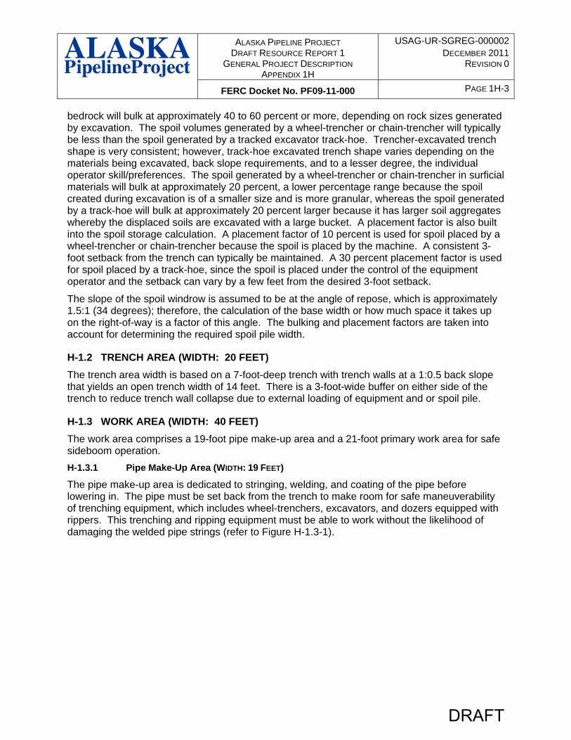
H-1.3.1 Pipe Make-Up Area (WIDTH: 19 FEET)
The pipe make-up area is dedicated to stringing, welding, and coating of the pipe before lowering in. The pipe must be set back from the trench to make room for safe maneuverability of trenching equipment, which includes wheel-trenchers, excavators, and dozers equipped with rippers. This trenching and ripping equipment must be able to work without the likelihood of damaging the welded pipe strings (refer to Figure H-1.3-1).
DRAFT

ALASKA PIPELINE PROJECT DRAFT RESOURCE REPORT 1
GENERAL PROJECT DESCRIPTION APPENDIX 1H
USAG-UR-SGREG-000002DECEMBER 2011
REVISION 0
FERC Docket No. PF09-11-000 PAGE 1H-4
FIGURE H-1.3-1. Dozer with Single Shank Ripper
When ripping the trench line with a dozer, the single tooth ripper will require sufficient space between ripping lanes to efficiently rip the full width of the trench. The spacing must be wide enough to prevent the tracks of the dozer from getting bogged down in the previously loose ripped soil.
The width of the ripping lane offset combined with the 19-foot-wide dozer blade will leave a safety buffer between the blade and the pipe and skids of 6.5 feet. The ripper will also need to have the option to rip the trench on an angle for ripping efficiency
The pipe make-up area also accommodates the welding shack (12-foot-wide) maneuverability and provides a safe work area around the welding shack.
H-1.3.2 Primary Work Area (WIDTH: 21 FEET)
The primary work lane will accommodate offloading of stringing trucks, welding, joint coating, and lowering-in operations. In the stringing phase, the space will be occupied by stringing trucks and strung pipe.
In the welding phase, the space will be used for sidebooms and welding shacks, the welded pipe string, and sidebooms with extended counter weight during lowering-in operations.
DRAFT
ALASKA PIPELINE PROJECT DRAFT RESOURCE REPORT 1
GENERAL PROJECT DESCRIPTION APPENDIX 1H
USAG-UR-SGREG-000002DECEMBER 2011
REVISION 0
FERC Docket No. PF09-11-000 PAGE 1H-5
The sideboom will take up 29-feet from the outside of the extended counterweights to the centerline of the suspended pipe with the boom in its neutral position. This distance will increase as the pipe is lowered into the trench during lowering-in operations.
H-1.4 TRAVEL AREA (WIDTH: 40 FEET)
The travel area comprises a 29-foot secondary work lane and an 11-foot-wide travel lane.
H-1.4.1 Secondary Work Lane (WIDTH: 29 FEET)
The secondary work lane is dedicated as a passing zone for moving equipment and materials up and down the construction right-of-way, such as welding shacks, maintenance vehicles, rock trucks, and fuel trucks. Sidebooms with welding shacks will require 29-feet of room while leap frogging around other welding shacks during welding operations.
H-1.4.2 Travel Lane (WIDTH: 11 FEET)
The travel lane is required for safe and efficient movement of the hundreds of daily pipe stringings and haulers, rock trucks, personnel, inspection staff, and other construction support vehicles. The lane will also be used for an emergency vehicle lane. The travel lane must remain unobstructed by sidebooms and other pipeline equipment to allow a large volume of traffic to move along the right-of-way in a timely manner.
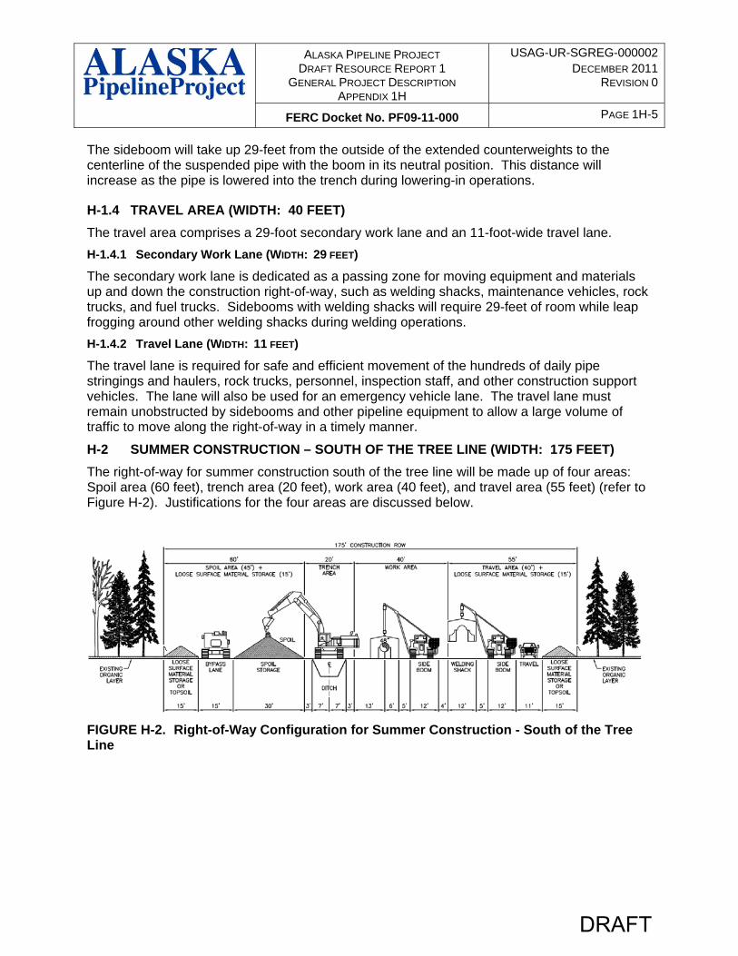
H-2 SUMMER CONSTRUCTION – SOUTH OF THE TREE LINE (WIDTH: 175 FEET)
The right-of-way for summer construction south of the tree line will be made up of four areas: Spoil area (60 feet), trench area (20 feet), work area (40 feet), and travel area (55 feet) (refer to Figure H-2). Justifications for the four areas are discussed below.
FIGURE H-2. Right-of-Way Configuration for Summer Construction - South of the Tree Line
DRAFT
ALASKA PIPELINE PROJECT DRAFT RESOURCE REPORT 1
GENERAL PROJECT DESCRIPTION APPENDIX 1H
USAG-UR-SGREG-000002DECEMBER 2011
REVISION 0
FERC Docket No. PF09-11-000 PAGE 1H-6
H-2.1 SPOIL AREA (WIDTH: 60 FEET)
The spoil storage area comprises a 15-foot-wide area for organic layer storage, a 15-foot-wide area for a bypass lane and a 30-foot-wide area for trench spoil.
H-2.1.1 Loose Surface Material Storage (WIDTH: 15 FEET)
In thaw-stable areas during summer construction, the loose surface materials are stored and used as a resource for reclamation purposes. In agricultural land topsoil will be stripped from all or only part of the right-of-way depending on circumstances. This reclamation material is windrowed to both sides of the proposed construction right-of-way for later use during reclamation. The volume of this material will vary depending on the type of vegetation cover and terrain.
During reclamation, the stored surface material will be re-spread over the finished graded slopes and workspaces.
H-2.1.2 Bypass Lane (WIDTH: 15 FEET)
This is a dedicated lane required to leap frog trenching equipment on the work side of the right-of-way alongside of the spoil pile. Unlike the loose surface material pile in winter construction, the loose surface material pile cannot be flattened down and driven on by heavy equipment.
Travel on the loose surface material pile must be prohibited to prevent the change that occurs in the soils composition from heavy traffic.
During reclamation, the loose surface material will be re-spread over the finished graded slopes and workspaces.
H-2.1.3 Spoil Storage (WIDTH: 30 FEET)
This is the same as for spoil storage for winter construction south of the tree line in Section H-1.1.2.
H-2.2 TRENCH AREA (WIDTH: 20 FEET)
This is the same as for the trench area for construction south of the tree line in Section H-1.2.
H-2.3 WORK AREA (WIDTH: 40 FEET)
This is the same as for the work area for construction south of the tree line in Section H-1.3.
H-2.4 TRAVEL AREA (WIDTH: 55 FEET)
The travel area in summer construction is similar to the winter construction right-of-way with a 29-foot-wide secondary work area and an 11-foot-wide travel lane, but has an additional 15 feet for loose surface material storage or topsoil where applicable.
DRAFT
ALASKA PIPELINE PROJECT DRAFT RESOURCE REPORT 1
GENERAL PROJECT DESCRIPTION APPENDIX 1H
USAG-UR-SGREG-000002DECEMBER 2011
REVISION 0
FERC Docket No. PF09-11-000 PAGE 1H-7
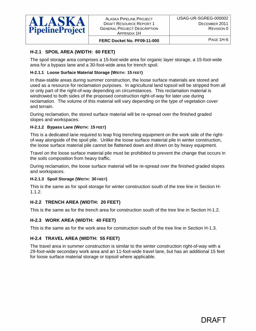
H-3 WINTER CONSTRUCTION - NORTH OF THE TREE LINE (WIDTH: 145 FEET)
The right-of-way for winter construction north of the tree line will be made up of four areas: Spoil area (45 feet), trench area (20 feet), work area (40 feet), and travel area (40 feet) (refer to Figure H-3).
This right-of-way configuration is similar to winter construction south of the tree line, except in this case the right-of-way is built up with a granular / snow and ice pad and that there will be no loose surface material as it will be frozen.
FIGURE H-3. Right-of-Way Configuration for Winter Construction - North of the Tree Line
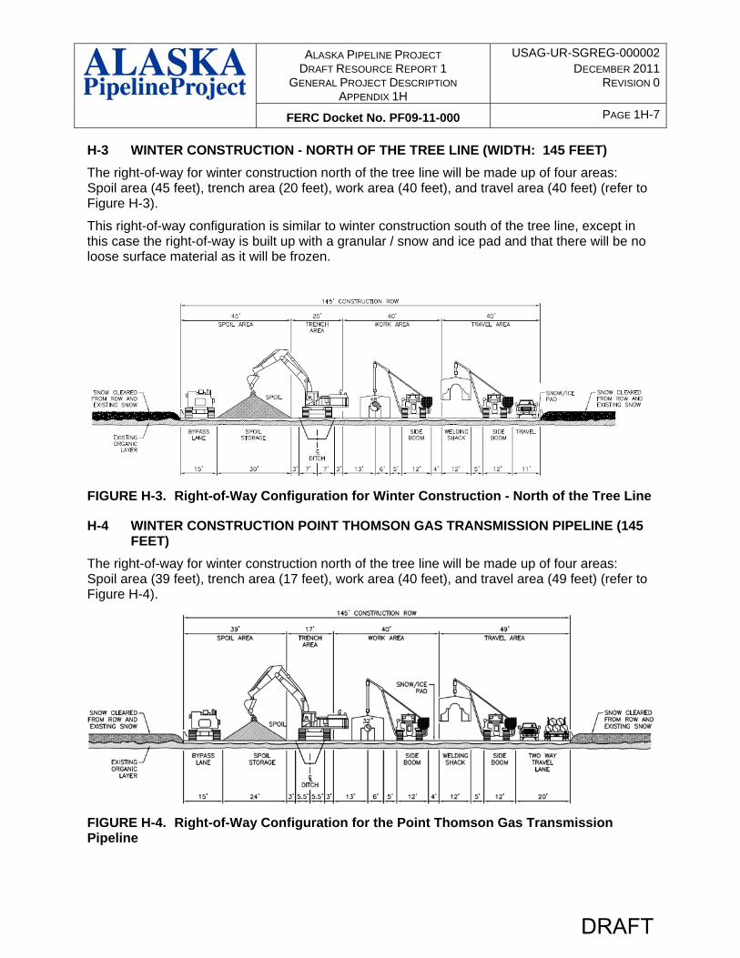
H-4 WINTER CONSTRUCTION POINT THOMSON GAS TRANSMISSION PIPELINE (145 FEET)
The right-of-way for winter construction north of the tree line will be made up of four areas: Spoil area (39 feet), trench area (17 feet), work area (40 feet), and travel area (49 feet) (refer to Figure H-4).
FIGURE H-4. Right-of-Way Configuration for the Point Thomson Gas Transmission Pipeline
DRAFT
ALASKA PIPELINE PROJECT DRAFT RESOURCE REPORT 1
GENERAL PROJECT DESCRIPTION APPENDIX 1H
USAG-UR-SGREG-000002DECEMBER 2011
REVISION 0
FERC Docket No. PF09-11-000 PAGE 1H-8
H-4.1 SPOIL AREA (WIDTH: 39 FEET)
The spoil storage area is comprised of a 15-foot-wide bypass lane and a 24-foot-wide area for trench spoil.
H-4.1.1 Bypass Lane (WIDTH: 15 FEET)
Same as winter construction discussed above.
H-4.1.2 Spoil Storage (WIDTH: 24 FEET)
The spoil storage for this pipeline takes into account the factors mentioned above; however, due to the significant reduction in size of the pipeline trench, the spoil storage pile will consume just 24-feet of right-of-way.
H-4.2 TRENCH AREA (WIDTH: 17 FEET)
The trench area width is based on a 5-foot-deep trench with trench walls at a 1:0.5 back slope, which yields an open trench width of 11 feet. There is a 3-foot-wide buffer on either side of the trench to reduce trench wall collapse due to external loading of equipment and/or spoil pile.
H-4.3 WORK AREA (WIDTH: 40 FEET)
Same as winter construction discussed above.
H-4.4 TRAVEL AREA (WIDTH: 49 FEET)
The travel area is comprised of a 29-foot-wide secondary work area and a 20-foot-wide travel lane.
H-4.4.1 Secondary Work Lane (WIDTH: 29 FEET)
Same as winter construction discussed above.
H-4.4.2 Travel Lane (WIDTH: 20 FEET)
The travel lane is required for safe and efficient movement of the pipe stringing and haulers, rock trucks, personnel, inspection staff, and other construction support vehicles, as in the cases mentioned above, however, there are no accesses to intermediate points along the Point Thomson Gas Transmission Pipeline (PT Pipeline) right-of-way and as a result, the right-of-way is the only access available to construct the pipeline.
The travel lane must be wide enough to safely accommodate two vehicles traveling in opposite directions during construction.
H-4.4.1 Secondary Work Lane (WIDTH: 29 FEET)
Same as winter construction discussed above.
H-4.4.2 Travel Lane (WIDTH: 20 FEET)
The travel lane is required for safe and efficient movement of the pipe stringing and haulers, rock trucks, personnel, inspection staff, and other construction support vehicles, as in the cases mentioned above. However, there is no access to intermediate points along the PT Pipeline right-of-way and as a result the right-of-way is the only access available to construct the pipeline.
DRAFT
ALASKA PIPELINE PROJECT DRAFT RESOURCE REPORT 1
GENERAL PROJECT DESCRIPTION APPENDIX 1H
USAG-UR-SGREG-000002DECEMBER 2011
REVISION 0
FERC Docket No. PF09-11-000 PAGE 1H-9
The travel lane must be wide enough to safely accommodate two vehicles traveling in opposite directions during construction.
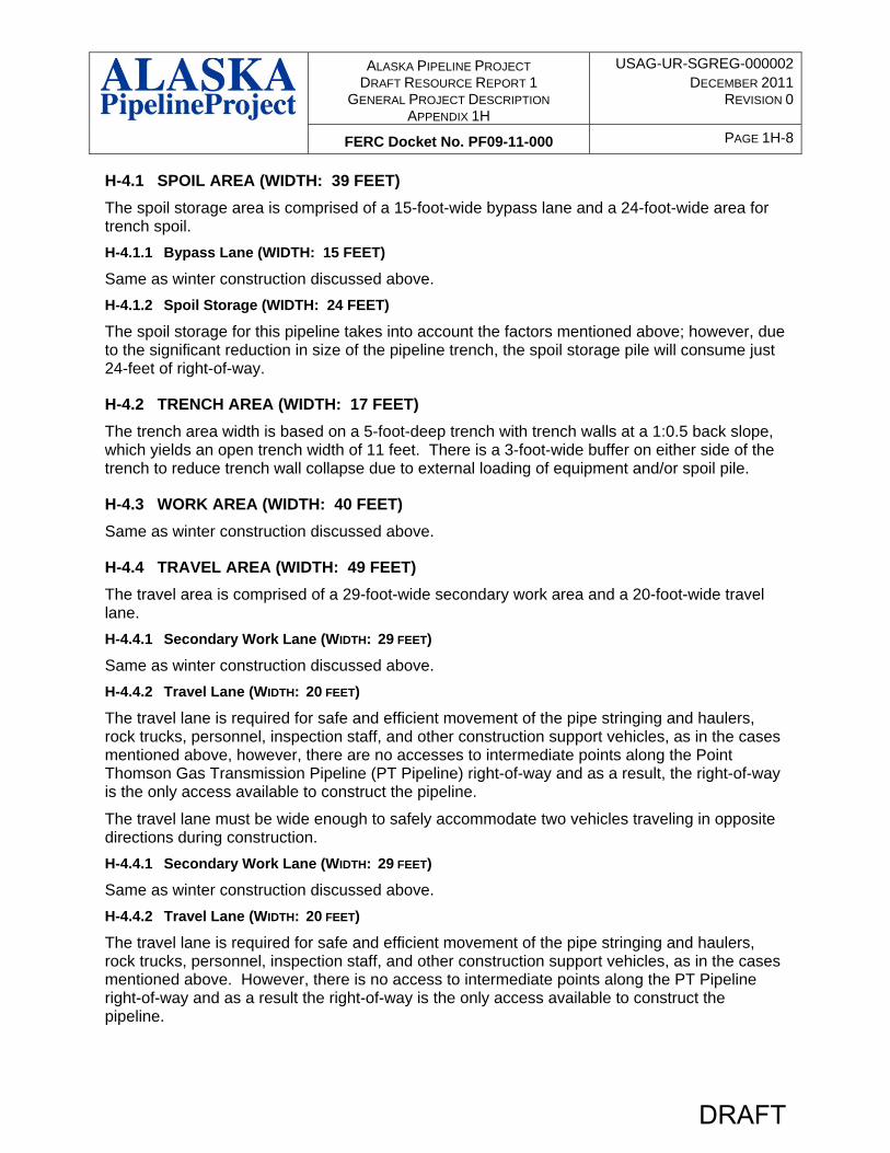
H-5 SIDE SLOPES NORTH OF TREE LINE
The right-of-way for winter construction north of the tree line on side slopes will be made up of four areas: Spoil area (45 feet), trench area (20 feet), work area (40 feet), and travel area (40 feet but varies) (refer to Figure H-5).
The right-of-way width north of the tree line will be required to be a minimum of 145-feet-wide; however, where side slopes occur, the width of the right-of-way will vary based on the degree of the side slope.
FIGURE H-5. Right-of-way Configuration for a Side Slope for Winter Construction - North of the Tree Line.
H-6 UNFROZEN WETLAND CROSSING – WINTER CONSTRUCTION
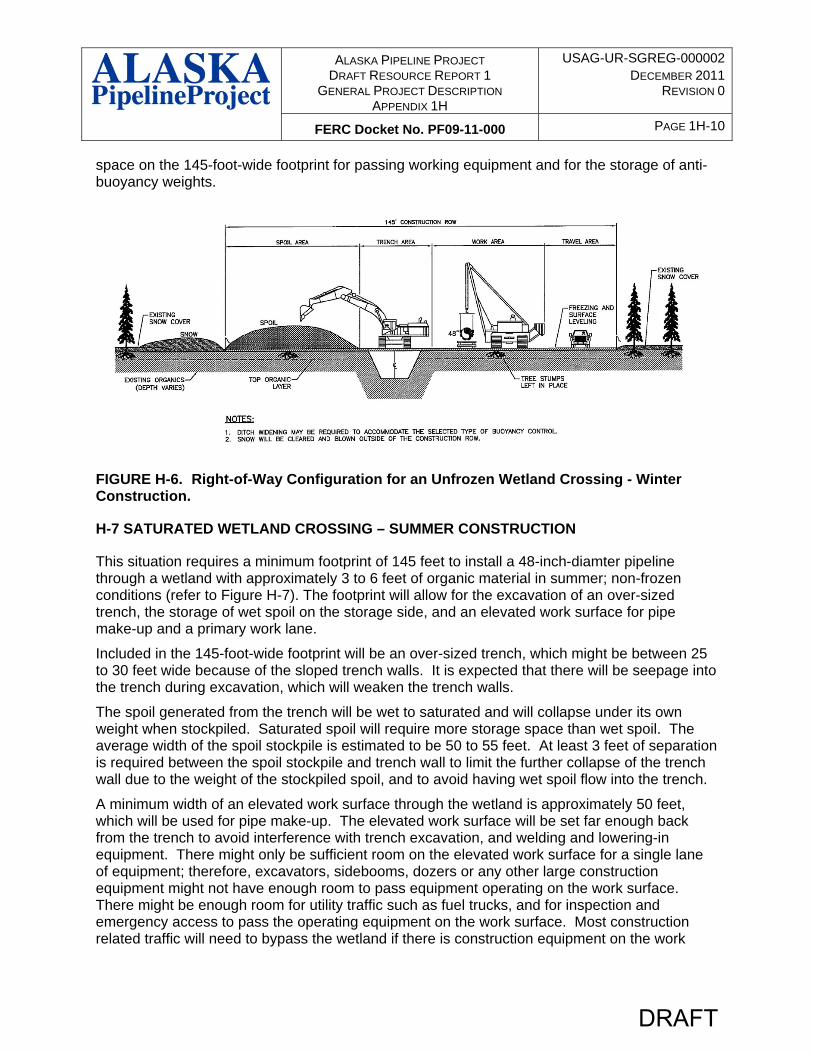
This situation requires a minimum footprint of 145 feet to install a 48-inch-diamter pipeline through a wetland with approximately 3 to 6 feet of organic material in the winter, where only the upper-most portion of the wetland is frozen (refer to Figure H-6).
Included in the 145-foot-wide footprint will be a moderately over-sized trench, which might be approximately 20 feet wide due to the frozen or semi-frozen nature of the trench walls. There could be seepage into the trench at depth during excavation, which might undermine the overlying frozen wetland surface and trench wall stability.
The spoil generated from the trench will be frozen to semi-frozen and should stockpile similar to mineral spoil. The average width of the spoil area is estimated to be 38 to 42 feet. At least 3 feet of separation is required between the spoil and trench wall to limit the amount of frozen spoil rolling back into the open trench.
The minimum width of a frozen work surface (work area plus travel area) through the wetland is approximately 80 feet, which will allow for standard productivity rates to occur. There will be
DRAFT
ALASKA PIPELINE PROJECT DRAFT RESOURCE REPORT 1
GENERAL PROJECT DESCRIPTION APPENDIX 1H
USAG-UR-SGREG-000002DECEMBER 2011
REVISION 0
FERC Docket No. PF09-11-000 PAGE 1H-10
space on the 145-foot-wide footprint for passing working equipment and for the storage of anti-buoyancy weights.
FIGURE H-6. Right-of-Way Configuration for an Unfrozen Wetland Crossing - Winter Construction.
H-7 SATURATED WETLAND CROSSING – SUMMER CONSTRUCTION
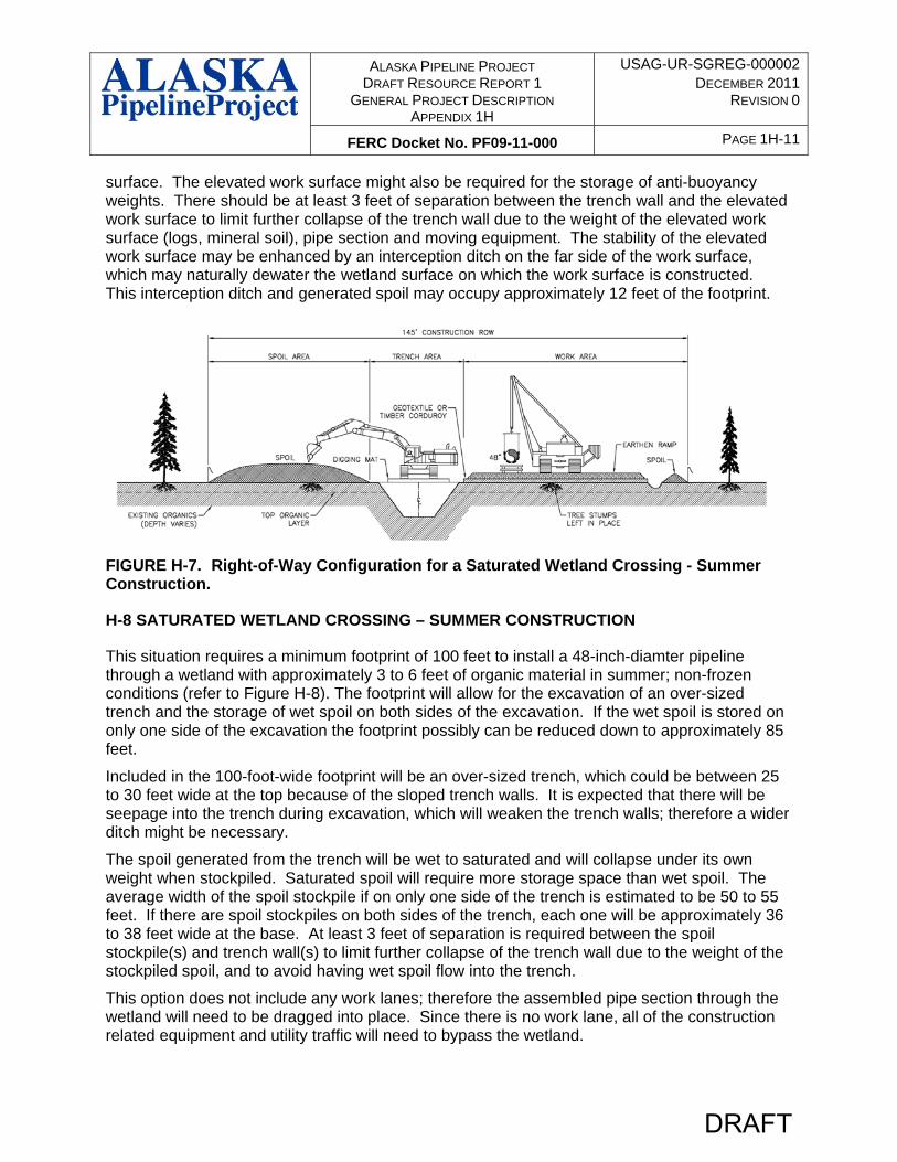
This situation requires a minimum footprint of 145 feet to install a 48-inch-diamter pipeline through a wetland with approximately 3 to 6 feet of organic material in summer; non-frozen conditions (refer to Figure H-7). The footprint will allow for the excavation of an over-sized trench, the storage of wet spoil on the storage side, and an elevated work surface for pipe make-up and a primary work lane.
Included in the 145-foot-wide footprint will be an over-sized trench, which might be between 25 to 30 feet wide because of the sloped trench walls. It is expected that there will be seepage into the trench during excavation, which will weaken the trench walls.
The spoil generated from the trench will be wet to saturated and will collapse under its own weight when stockpiled. Saturated spoil will require more storage space than wet spoil. The average width of the spoil stockpile is estimated to be 50 to 55 feet. At least 3 feet of separation is required between the spoil stockpile and trench wall to limit the further collapse of the trench wall due to the weight of the stockpiled spoil, and to avoid having wet spoil flow into the trench.
A minimum width of an elevated work surface through the wetland is approximately 50 feet, which will be used for pipe make-up. The elevated work surface will be set far enough back from the trench to avoid interference with trench excavation, and welding and lowering-in equipment. There might only be sufficient room on the elevated work surface for a single lane of equipment; therefore, excavators, sidebooms, dozers or any other large construction equipment might not have enough room to pass equipment operating on the work surface. There might be enough room for utility traffic such as fuel trucks, and for inspection and emergency access to pass the operating equipment on the work surface. Most construction related traffic will need to bypass the wetland if there is construction equipment on the work
DRAFT
ALASKA PIPELINE PROJECT DRAFT RESOURCE REPORT 1
GENERAL PROJECT DESCRIPTION APPENDIX 1H
USAG-UR-SGREG-000002DECEMBER 2011
REVISION 0
FERC Docket No. PF09-11-000 PAGE 1H-11
surface. The elevated work surface might also be required for the storage of anti-buoyancy weights. There should be at least 3 feet of separation between the trench wall and the elevated work surface to limit further collapse of the trench wall due to the weight of the elevated work surface (logs, mineral soil), pipe section and moving equipment. The stability of the elevated work surface may be enhanced by an interception ditch on the far side of the work surface, which may naturally dewater the wetland surface on which the work surface is constructed. This interception ditch and generated spoil may occupy approximately 12 feet of the footprint.
FIGURE H-7. Right-of-Way Configuration for a Saturated Wetland Crossing - Summer Construction.
H-8 SATURATED WETLAND CROSSING – SUMMER CONSTRUCTION
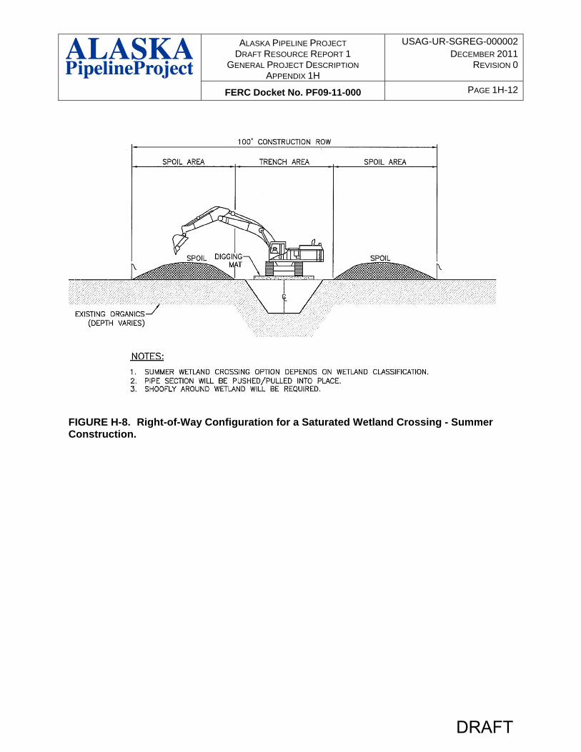
This situation requires a minimum footprint of 100 feet to install a 48-inch-diamter pipeline through a wetland with approximately 3 to 6 feet of organic material in summer; non-frozen conditions (refer to Figure H-8). The footprint will allow for the excavation of an over-sized trench and the storage of wet spoil on both sides of the excavation. If the wet spoil is stored on only one side of the excavation the footprint possibly can be reduced down to approximately 85 feet.
Included in the 100-foot-wide footprint will be an over-sized trench, which could be between 25 to 30 feet wide at the top because of the sloped trench walls. It is expected that there will be seepage into the trench during excavation, which will weaken the trench walls; therefore a wider ditch might be necessary.
The spoil generated from the trench will be wet to saturated and will collapse under its own weight when stockpiled. Saturated spoil will require more storage space than wet spoil. The average width of the spoil stockpile if on only one side of the trench is estimated to be 50 to 55 feet. If there are spoil stockpiles on both sides of the trench, each one will be approximately 36 to 38 feet wide at the base. At least 3 feet of separation is required between the spoil stockpile(s) and trench wall(s) to limit further collapse of the trench wall due to the weight of the stockpiled spoil, and to avoid having wet spoil flow into the trench.
This option does not include any work lanes; therefore the assembled pipe section through the wetland will need to be dragged into place. Since there is no work lane, all of the construction related equipment and utility traffic will need to bypass the wetland.
DRAFT
ALASKA PIPELINE PROJECT DRAFT RESOURCE REPORT 1
GENERAL PROJECT DESCRIPTION APPENDIX 1H
USAG-UR-SGREG-000002DECEMBER 2011
REVISION 0
FERC Docket No. PF09-11-000 PAGE 1H-12
FIGURE H-8. Right-of-Way Configuration for a Saturated Wetland Crossing - Summer Construction.
DRAFT
ALASKA PIPELINE PROJECT DRAFT RESOURCE REPORT 1
GENERAL PROJECT DESCRIPTION APPENDIX 1H
USAG-UR-SGREG-000002DECEMBER 2011
REVISION 0
FERC Docket No. PF09-11-000 PAGE 1H-13
PERMANENT RIGHT-OF-WAY RATIONALE
APP has identified the need to retain a permanent right-of-way of 80 feet for the 32-inch diameter PT Pipeline and 100 feet for the 48-inch diameter Alaska Mainline. As described in Resource Report 1, where practical, the pipeline facilities will generally collocate with other infrastructure corridors (e.g. above and below ground third-party utilities; roads and highways). The existing infrastructure corridors provide access to the Pipeline Facilities in some areas; however, a significant portion of the permanent right-of-way will be located within geographically remote areas and will be accessed mainly by helicopter.
During normal operations APP will require access to various points along the permanent right-of-way to conduct inspection and maintenance activities on the pipeline and aboveground facilities. These inspection and maintenance activities are identified in the Integrity Management Program (IMP) discussed in Resource Report 11 and include accessing:
o Mainline Block Valves (MLBV) located approximately every 20 miles in between compressor stations,
o Cathodic protection test leads installed approximately every 2 miles along the pipeline;
o Short sections of the buried pipeline along the permanent right-of-way for investigative digs; and
o Sections of the permanent right-of-way requiring erosion control, slope stability management, and drainage mitigation/control;
APP Aviation Standards will require a stable and flat landing surface with minimum dimensions of 100 feet x 100 feet, that is cleared of trees and tall growth. In conjunction with the 100 foot square cleared landing area, APP procedures will require additional clearing within the 100 foot Right-of-way in order to allow for safe helicopter access/egress to these locations.
Maintenance of the buried pipeline may require excavation to expose a short length of the pipeline for visual inspection or pipe alignment using various pieces of equipment described in Resource Report 1, Section 1.6. The pipeline facilities may have up to five feet of cover over the top of the buried pipeline. APP excavation procedures will require width along the permanent right-of-way for the trench slope to have a safe slope and a safety buffer zone away from the trench slope plus room for excavation and maintenance equipment. The width of the trench opening, assuming a trench slope of 1:1 at the surface grade will be approximately 13 feet to 16 feet for the PT Pipeline and 19 feet to 22 feet for Alaska Mainline. The excavated spoil from the trench will require approximately 23 feet for PT Pipeline and 29 feet for the Alaska Mainline. Furthermore, the safety buffer zone will require approximately 39 feet for the PT Pipeline and 49 feet for the Alaska Mainline to accommodate maintenance and excavation equipment. Overall, the permanent right-of-way width required to perform IMP periodic investigative digs along the pipeline is approximately 80 feet for the PT Pipeline and 100 feet for the Alaska Mainline. Maintenance excavation can be safely performed within a narrower right-of-way along short sections of the pipeline than is required during initial construction, due to the smaller scope of work, volume of equipment, and manpower.
DRAFT


![[XLS] · Web viewrptAppendix 7 AIRCRAFT NOISE DATA FOR U.S. CERTIFICATED PROPELLER DRIVEN SMALL AIRPLANES (14 CFR PART 36, APPENDIX F) (FROM AC36-1H APPENDIX 7, NOVEMBER 15, 2001)](https://img.dokumen.tips/doc/110x75/5b1d0f977f8b9a3b618c07bb/xls-web-viewrptappendix-7-aircraft-noise-data-for-us-certificated-propeller.jpg)