Embed Size (px)
Citation preview

Appendix 15
Outfall Capacity Review
Report
Gisborne District Council - Outfall Capacity Review & Design Basis Report
Prepared for Gisborne District Council
Prepared by CH2M Beca Ltd
23 June 2017

Gisborne District Council - Outfall Capacity Review & Design Basis Report
CH2M Beca // 23 June 2017
6519032 // NZ1-13646030-31 0.31 // i
Revision History
Revision Nº Prepared By Description Date
A Nick Koppel/ Rob Fullerton Draft
B Nick Koppel/ Rob Fullerton Final 23 June 2017
Document Acceptance
Action Name Signed Date
Prepared by Nick Koppel, Rob Fullerton
23 June 2017
Reviewed by Rachael Shaw
23 June 2017
Approved by Garry Macdonald
23 June 2017
on behalf of CH2M Beca Ltd
© CH2M Beca 2017 (unless CH2M Beca has expressly agreed otherwise with the Client in writing).
This report has been prepared by CH2M Beca on the specific instructions of our Client. It is solely for our Client’s use for the purpose for which it is intended in accordance with the agreed scope of work. Any use or reliance by any person contrary to the above, to which Beca has not given its prior written consent, is at that person's own risk.

Gisborne District Council - Outfall Capacity Review & Design Basis Report
CH2M Beca // 23 June 2017
6519032 // NZ1-13646030-31 0.31 // ii
Contents
1 Introduction 1
2 Review of previous reports 1
2.1 Original design 1
2.2 Outfall Capacity 2
2.3 Duckbill Valves 2
2.4 Outfall Condition 6
2.5 Design Basis 7
3 Head loss modelling 8
4 Relining the outfall 9
5 Conclusion and Recommendation 10

Gisborne District Council - Outfall Capacity Review & Design Basis Report
CH2M Beca // 23 June 2017
6519032 // NZ1-13646030-31 0.31 // page 1
1 Introduction
Gisborne District Council (GDC) has commissioned CH2M Beca (Beca) to review the capacity of the existing
ocean outfall and prepare a report summarising the previous work done on the outfall.
The scope of the study is to:
� Review previous reports regarding the outfall pipeline
� Develop a basis of design for estimating the capacity of the outfall
� Confirm the current capacity of the outfall in its existing configuration
� Estimate the capacity if all ports are fitted with duckbill valves
� Identify a method for lining the outfall and provide an order-of-magnitude cost estimate for this
The following table provides a list of the historic reports prepared in relation to the Gisborne District Council
wastewater outfall pipeline:
Number Report References Author Year
1 The Gisborne Submarine Sewer Outfall. The Journal of New Zealand Institute of Engineers, 21(3), 110-119
Williams, H. GDC 1966
2 Gisborne Submarine Outfall Nine Years in Retrospect Williams, H. GDC 1974
3 System Study and Outfall Survey for Gisborne Sewage System. Steven Fitzmaurice & Partners Ltd
1988
4 Gisborne Outfall Evaluation of Diffuser Check Valve. BECA STEVEN 1995
5 Gisborne District Council Sewer Outfall Condition Assessment. Opus 2015
6 Outfall Cleaning – Options. CH2M Beca 2008
7 Duckbill Valve Testing. CH2M Beca 2008
8 Gisborne Design Peak Flows and Outfall Capacity. Beca CH2M Beca 2008
9 Brown, P. Gisborne Outfall Model. CH2M Beca CH2M Beca 2009
10 Gisborne Sewage Outfall Dive Inspection. FMS Fielder Marine
Service Limited 2015
11 Cross, I. Desktop Review of Status Gisborne City Outfall. OCEL Consultants NZ Limited
2016
2 Review of previous reports
2.1 Original design
The ocean outfall was originally designed by Harold Williams (GCC Engineer) in the 1960s comprising a
6000ft (1829m) long 30in (762mm) diameter pre-tensioned concrete pipe with a 600ft (~180m) diffuser
section. The diffuser section was fitted with 44 plugged 5.5in (140mm) diameter steel rimed diffuser ports in
a 90 degree pattern around the circumference.
Once the pipe was laid, 22 of the plugged diffuser ports were opened as the other 22 were positioned on the
underside of the pipe and buried in sediment. A 12in (300mm) diameter end port was also included to
provide back pressure allowing five-sixths of the flow to emerge evenly out of the ports along the diffusers
length.

Gisborne District Council - Outfall Capacity Review & Design Basis Report
CH2M Beca // 23 June 2017
6519032 // NZ1-13646030-31 0.31 // page 2
The outfall was originally designed with an ultimate flow capacity of 12.3mgd (~540l/s) with a flow velocity of
4.6ft/s (1.4m/s) to match the capacity of the pumps installed.
The N.Z. Engineering paper (Williams 1966) notes a representative selection of pipe sections were tested to
a pressure of 18.3m (60 ft). It is not stated in the paper whether this was considered a maximum operating
pressure or a working pressure.
2.2 Outfall Capacity
In 1988 Steven Fitzmaurice & Partners conducted a capacity study of the outfall. The study assumed a
safety factor of 1.50 was applied to the 18.3m test pressure and is the basis for the operating head (12.2m)
stated in subsequent reports regarding the GDC outfall. It was concluded that at the maximum working
hydrostatic head of 12.2m the outfall would have a maximum flow capacity of 922l/s. GDC then
commissioned Beca Steven in 1995 to investigate the installation of duckbill valves on the diffuser ports to
improve dilution and reduce sand infiltration into the outfall pipe. The model previously developed by Steven
Fitzmaurice was modified to include duckbill valves and the outfall capacity was estimated to be 850l/s with
duckbill valves fitted to the diffuser ports. An additional 1.2m of head was required to achieve the previously
estimated capacity of 922l/s.
In 2009 a third capacity review of the outfall was conducted by CH2M Beca to investigate the implications of
the build-up of sediment in the pipe and the fitting of new duckbill valves to the diffuser ports. A new
wastewater system was proposed for Gisborne which would deliver approximately 930l/s of flow to the
outfall. It was concluded that with duckbill valves installed the outfall are unlikely to be able to pass this flow
at the maximum head of 12m.
A further capacity study of the outfall was conducted by OCEL in 2016. This concluded that a driving head of
>12m is required at a flow rate of 900l/s suggesting that the capacity of the outfall is less than 900l/s if the
maximum driving head of 12m is assumed. Blocking off 5 ports increased the headloss by approximately
0.5m, which simulates the effect port blockages may have on pumping head requirements.
2.3 Duckbill Valves
In 1974 Harold Williams reviewed the performance of the ocean outfall and indicated that “some form of plug
in nozzle contraption” could be fitted to some of the diffuser ports to improve dilution if required. Subsequent
to this, GDC has considered the installation of duckbill valves to the diffuser ports and a number of
investigations have been undertaken. The specific arrangement and time of installation of the early duckbill
valves is not known.
As well as adding to initial dilution, the other advantage of duckbill valves is that they reduce the risk of sand
and other marine organisms and materials entering the outfall pipe through otherwise fully open ports, which
are then difficult to remove from the pipe.
In 1995 the installation of duckbill valves was investigated and subsequently duckbill valves manufactured by
Skellerup were installed, although the exact number of ports fitted with duckbill valves is uncertain. In
2010/2011all the Skellerup duckbill valves were removed and replaced with culvert socks. The 2015 dive
survey identified a number of blocked ports; each of these ports were then fitted with Duckbill valves sourced
by Greenfield Diving Services (GDS). Large (125mm diameter) duckbill valves were fitted to ports 5, 7 and 8.
Small (100mm diameter) duckbill valves were fitted to ports 12, 13, 14, 15, 20 and 21.
Gisborne District Council - Outfall Capacity Review & Design Basis Report
CH2M Beca // 23 June 2017
6519032 // NZ1-13646030-31 0.31 // page 3
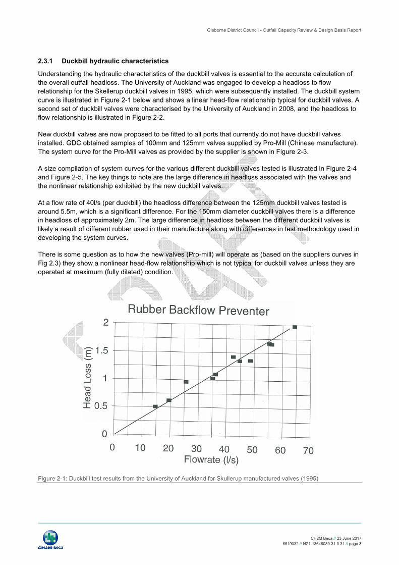
2.3.1 Duckbill hydraulic characteristics
Understanding the hydraulic characteristics of the duckbill valves is essential to the accurate calculation of
the overall outfall headloss. The University of Auckland was engaged to develop a headloss to flow
relationship for the Skellerup duckbill valves in 1995, which were subsequently installed. The duckbill system
curve is illustrated in Figure 2-1 below and shows a linear head-flow relationship typical for duckbill valves. A
second set of duckbill valves were characterised by the University of Auckland in 2008, and the headloss to
flow relationship is illustrated in Figure 2-2.
New duckbill valves are now proposed to be fitted to all ports that currently do not have duckbill valves
installed. GDC obtained samples of 100mm and 125mm valves supplied by Pro-Mill (Chinese manufacture).
The system curve for the Pro-Mill valves as provided by the supplier is shown in Figure 2-3.
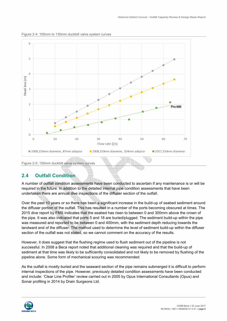
A size compilation of system curves for the various different duckbill valves tested is illustrated in Figure 2-4
and Figure 2-5. The key things to note are the large difference in headloss associated with the valves and
the nonlinear relationship exhibited by the new duckbill valves.
At a flow rate of 40l/s (per duckbill) the headloss difference between the 125mm duckbill valves tested is
around 5.5m, which is a significant difference. For the 150mm diameter duckbill valves there is a difference
in headloss of approximately 2m. The large difference in headloss between the different duckbill valves is
likely a result of different rubber used in their manufacture along with differences in test methodology used in
developing the system curves.
There is some question as to how the new valves (Pro-mill) will operate as (based on the suppliers curves in
Fig 2.3) they show a nonlinear head-flow relationship which is not typical for duckbill valves unless they are
operated at maximum (fully dilated) condition.
Figure 2-1: Duckbill test results from the University of Auckland for Skullerup manufactured valves (1995)

Gisborne District Council - Outfall Capacity Review & Design Basis Report
CH2M Beca // 23 June 2017
6519032 // NZ1-13646030-31 0.31 // page 4
Following this evaluation of the Pro-mill valve characteristics GDC made inquiries of the Tideflex duckbill
valve manufacturer for information on their standard and wide bill valves. Tideflex valves are the original
duckbill valve in the market with successful experience of outfall applications over many years around the
world. The wide bill valve is optimised for improved dilution at low flows. Performance head/flow curves were
provided for the standard and wide bill 100mm and 125mm valves by the supplier.
The standard Tideflex valve curves compare favourably with earlier data used in the Beca diffuser headloss
model. The wide bill valves exhibit a significantly lower headloss relationship. The diffuser model has been
evaluated for both Tideflex valve combinations.
Figure 2-2: Duckbill test results from the University of Auckland (2008)
Skullerup

Gisborne District Council - Outfall Capacity Review & Design Basis Report
CH2M Beca // 23 June 2017
6519032 // NZ1-13646030-31 0.31 // page 5
Figure 2-3: System curve for proposed new duckbill valves (Pro-Mill)
Skullerup
Pro-Mill
Pro-Mill
Gisborne District Council - Outfall Capacity Review & Design Basis Report
CH2M Beca // 23 June 2017
6519032 // NZ1-13646030-31 0.31 // page 6
Figure 2-4: 100mm to 130mm duckbill valve system curves
Figure 2-5: 150mm duckbill valve system curves
2.4 Outfall Condition
A number of outfall condition assessments have been conducted to ascertain if any maintenance is or will be
required in the future. In addition to the detailed internal pipe condition assessments that have been
undertaken there are annual dive inspections of the diffuser section of the outfall.
Over the past 10 years or so there has been a significant increase in the build-up of seabed sediment around
the diffuser portion of the outfall. This has resulted in a number of the ports becoming obscured at times. The
2015 dive report by FMS indicates that the seabed has risen to between 0 and 300mm above the crown of
the pipe. It was also indicated that ports 5 and 18 are buried/plugged. The sediment build-up within the pipe
was measured and reported to be between 0 and 400mm, with the sediment depth reducing towards the
landward end of the diffuser. The method used to determine the level of sediment build-up within the diffuser
section of the outfall was not stated, so we cannot comment on the accuracy of the results.
However, it does suggest that the flushing regime used to flush sediment out of the pipeline is not
successful. In 2008 a Beca report noted that additional cleaning was required and that the build-up of
sediment at that time was likely to be sufficiently consolidated and not likely to be removed by flushing of the
pipeline alone. Some form of mechanical scouring was recommended.
As the outfall is mostly buried and the seaward section of the pipe remains submerged it is difficult to perform
internal inspections of the pipe. However, previously detailed condition assessments have been conducted
and include: ‘Clear Line Profiler’ review carried out in 2005 by Opus International Consultants (Opus) and
Sonar profiling in 2014 by Drain Surgeons Ltd.
Pro-Mill

Gisborne District Council - Outfall Capacity Review & Design Basis Report
CH2M Beca // 23 June 2017
6519032 // NZ1-13646030-31 0.31 // page 7
The condition assessment conducted by Opus in 2005 included Clear Line Profiling of the pipe along with
concrete coring at critical locations. The Clear Line Profiler consists of an extension probe on the front of a
standard tractor type CCTV camera. A laser is projected from the probe onto the inside surface of the pipe,
the camera records the image and compares it to an image representing the original pipe. The difference is
analysed and represents the loss of material within the pipe.
This inspection viewed 130m of pipe above the high tide line, which is 20m from the start of the pre-stressed
portion of the pipe. Two 100mm by 200mm concrete cores were found in the invert of the pipe. Strips of
erosion of the soffit of the pipe were observed on the upstream side of a number of pipe joins in the reaches
9m to 25m and 48-100m from the start of the pipe to the end of the wall of the pump station wet-well. These
isolated strips measured less than 250mm wide and did not occur past the 100m mark.
Analysis of the Clear Line Profiler results indicates erosion inside the soffit of the pipe of between 7.2mm
11.4mm. However, this only occurred at localised points (68-70m and 92-98m). Concrete cores were taken
at points of maximum corrosion as identified by the clear line profiler, which indicated erosion of 6mm.
Erosion was not detected outside of the reaches 9-25m and 48-100m.
In 2014 a further internal condition assessment was conducted by Drain Surgeons Limited using a sonar
profiler. This covered 1013m of the pipe and apart from an isolated obstruction of the bottom of the pipe near
the commencement of the survey there is very little sediment or debris build-up.
From the condition assessments it can be concluded that there is no significant issues with the structural
integrity outfall pipeline and repairs are not likely required for a number of years. The points of maximum
corrosion occur where the pipe may at times not run full allowing oxygen and other corrosive products to
form and corrode the surface of the pipe.
2.5 Design Basis
Based on the review of previous reports associated with the Gisborne outfall a design basis has been
developed for estimating the current capacity of the pipeline with duckbill valves fitted to all diffuser ports.
Table 2-1, provides the design basis information.
Table 2-1: Design basis information for the outfall pipeline
Parameter Unit Value
Pipe ID Mm 762
Pipe length M 1829
Diffuser length1 M 183 (600ft)
Diffuser slope m/m 0.003
Water depth over diffuser (mean sea level ) M 17.6
Water depth over diffuser ( mean high water springs)
M 16.9
Water depth over the
Number of diffuser ports No. 22 + end cap port
Diffuser port diameter mm 140
End cap duckbill valves No. 2 x 125mm diameter valves
Duckbill valve diameters Large and small 125mm and 100mm
Number of small (100mm diameter) duckbill valves
No. 11
Number of large (125mm diameter) duckbill valves
No. 11 + 2 end cap
Spacing between ports2 m 4.9 – 9.8

Gisborne District Council - Outfall Capacity Review & Design Basis Report
CH2M Beca // 23 June 2017
6519032 // NZ1-13646030-31 0.31 // page 8
Parameter Unit Value
Specific gravity of effluent Kg/kg 0.998
Specific gravity of sea water Kg/kg 1.026
Average grade of pipe mm/mm 0.003
Outfall pipe roughness coefficient m 0.0015
1 Taken from N.Z. Engineering paper (Williams 1966)
2 Approximate as spacing between ports varies across the full length of the diffuser section
3 Head loss modelling
A hydraulic model of the outfall was used to assess the maximum flow capacity with a 12m head limitation
under the following conditions The key assumptions made in estimating the current and future capacity of the
outfall are outlined below:
� Pipe roughness coefficient of 0.0015m
� Landward 11ports fitted with 100mm duckbill valves
� Seaward 11 ports fitted with 125mm duckbill valves
� End port fitted with two125mm duckbill valves
� Diffuser port entrance loss Cv = 0.75 (elbow port)
� Tide Flex valve head to flow relationships have been used for the currently installed duckbill valves and
the proposed new duckbill valves.
� Both standard TF and wide bill TF valves evaluated
Based on the assumptions above, and the design basis in the previous section of this report, a preliminary
capacity of the outfall in its current configuration and its proposed future configuration (all 23 ports fitted with
Duckbill valves) has been estimated (Figure 3-1).
The current capacity of the outfall at 12m operating head has been estimated to be approximately ~870L/s
(125mm duck bill valves on ports 5, 7, 8 + 100mm duck bill valves on ports 12, 13, 14, 15, 20, 21).
For the standard TF duckbill valve the capacity of the outfall is estimated as 823L/s. The wide bill operating
capacity is estimated as 882L/s. The difference in diffuser operating head between the standard TF valve
and the wide bill valve is 1.6m (3.3m vs 1.7m). The lower headloss for the wide bill valve allows an increase
in flow capacity from 823L/s to 882L/s at a maximum outfall pressure of 12m head.
The hydraulic model of the outfall capacity with all ports operating with duckbill valves as per the proposed
configuration, confirms that >12m of driving head will be required to achieve a flow rate of 900l/s from the
outfall in this future configuration.

Gisborne District Council - Outfall Capacity Review & Design Basis Report
CH2M Beca // 23 June 2017
6519032 // NZ1-13646030-31 0.31 // page 9
Figure 3-1: Capacity estimate of outfall, current configuration and proposed future configuration
This capacity model of the outfall estimated for the current configuration and future configuration with all
ports fitted with duckbill valves is consistent with the previous modelling and reports.
4 Relining the outfall
The new wastewater system proposed for Gisborne requires approximately 930l/s of flow to the outfall. To
achieve this flow rate with the Tideflex wide bill configuration the estimated pumping head required is ~13m.
For the standard Tideflex duck bill configuration the required head is ~15m.
A preliminary assessment of relining the outfall to extend the operating life and to enable peak flow
discharge of 930L/s by allowing increased pumping pressure has been modelled. Initial options have
considered pulling a smaller diameter PE or fuseable PVC (FPVC) continuously welded pipe through the
outfall with a new diffuser. A PE pipe with ID 624mm and a diffuser with the same configuration as the
current outfall was modelled. The 630mm diam FPVC (internal diam ~ 570mm) pipe is the largest diameter
available in New Zealand and would result in further headloss due to the smaller diameter; larger diameter
FPVC pipes could be imported as they have a thinner wall than the equivalent PE pipe, resulting in a larger
internal diameter.
The overall hydraulic analysis confirms that the headloss of the outfall pipe, not the diffuser, is the dominant
factor (even with a reduced friction factor of 0.5mm for PE pipe). For the same diffuser configuration with
widebill TF duckbills the outfall pipe headloss is some 23m with the diffuser headloss (port + duckbill) adding
only 2.2m for a total headloss of ~25.2m at a flow of 900L/s. For the standard TF valve the total headloss is
~26.3m at a flow of 900L/s. Should relining proceed in the future, the outfall pumps would need to be
upgraded for the higher hydraulic duty and to match the post Drainwise anticipated peak flow.

Gisborne District Council - Outfall Capacity Review & Design Basis Report
CH2M Beca // 23 June 2017
6519032 // NZ1-13646030-31 0.31 // page 10
A preliminary methodology and cost estimate to reline the outfall using the 630mm FPVC pipe has been
prepared by a contractor experienced in marine outfall works. The contractor has indicated that the
preferred methodology would be as follows:
� Float the welded string of PE (or FPVC) pipe out to sea with both ends sealed.
� Remove the seals causing the pipe to sink to the bottom.
� Attach a pulling rope and then pull it into the existing outfall.
� The annulus around the pipe would be sufficient for the discharge of the outfall to continue virtually
unimpaired.
� The pipe would be pulled open ended in that way eliminating the need for a temporary by-pass pipe i.e.
the majority of the works would be done live.
� A period of no flow would be required to allow the landward connections to be made. Such tie-in works
are not uncommon and could be scheduled at low flow periods, and only take a matter of hours.
� The new pipe would not be grouted and would sit loose inside the host pipe, except on the landside at the
pulling pit. The weight of the FPVC will ensure that the new pipe would sit at the bottom of the existing
pipe.
� A purpose designed diffuser section would be fitted to the end, which would effectively extend the outfall
length by a similar length to the existing diffuser section.
Based on 2km of relining and a preliminary bill of quantities, the order of magnitude cost of outfall relining is
estimated to be about $2.7M including a new diffuser section. A further allowance of approximately $0.5M
for design, consenting and other costs should be included. Should relining be required in the future, a
detailed hydraulic design and engineers estimate is recommended. This should include further investigation
of the availability of larger diameter FPVC to reduce the overall friction losses. It should also be based on
the post Drainwise implementation peak flows.
5 Conclusion and Recommendation
The key assumption in defining the maximum flow capacity of the outfall is the 12m pressure limitation based
on the earlier test pressure results reported by H Williams. If this limit could be lifted, through either assuming
a lower safety factor on the pipe (not recommended) or inserting a higher-pressure rated liner pipe, the
outfall capacity could be increased as the outfall pumps can pump at a higher rate.
The analysis undertaken is only for static hydraulic conditions, with the 12m limit, and we recommend that a
surge analysis of the whole outfall pipeline from the pump station to the diffuser be undertaken when the new
duckbill characteristics are confirmed and included in the outfall model. The situation to be tested in the
surge analysis is a sudden shutdown of the outfall pumps when operating at close to full speed to determine
if the 12m pressure limit is exceeded anywhere along the outfall pipeline.