Embed Size (px)
Citation preview

appendices 8-1
Absorption
Transformation of radiant energy to a different form of energy by the intervention
of matter.
Adaptation
The process by which the state of the human visual system is modified by previous
and present exposure to stimuli that may have various luminances, spectral
distributions, and angular subtenses.
Altitude
The angular distance of the sun measured upward from the horizon on the vertical
plane that passes through the sun. Altitude is measured positively from horizon to
zenith from 0° to 90°.
Angle of Incidence
The angle between a ray of light falling on a surface and a line perpendicular to
the surface.
Atmospheric Turbidity
The scattering of solar radiation caused by air molecules, the scattering and absorption
of solar radiation by larger particles known as aerosols, and the absorption of solar
radiation by atmospheric gases and water vapour in the atmosphere. Atmospheric
turbidity is usually expressed as the ratio of the total attenuation from molecules and
aerosols in the atmosphere to that of molecules alone, using coefficients or optical
thicknesses of molecular and particulate atmospheres. Atmospheric turbidity values
Appendices 8.
Glossary 8.1.

8-2 daylight in buildings
of 3 to 6 are common even on days described as clear. A value of unity is equivalent
to a Rayleigh atmosphere in which the size of particles is small compared with the
wavelength of the radiation.
Atrium
An interior light space enclosed laterally by the walls of a building and covered with
transparent or translucent material that permits light to enter interior spaces through
pass-through components.
Azimuth
The azimuth of the sun is the angle between the vertical plane containing the sun and
the vertical plane oriented to the north (direction of origin).
Brightness
The visual sensation by which an observer registers the degree to which a surface
appears to emit or reflect more or less light. This subjective sensation cannot be
measured in absolute units; it describes the appearance of a source or object.
Candela
The unit of luminous intensity. The luminance of a full radiator at the temperature of
solidification of platinum is 60 candelas / cm2.
Candela Per Square Meter
A unit of luminance in a particular direction recommended by the Commission
Internationale de L’Éclairage (CIE).
CIE Standard Clear Sky
Cloudless sky for which the relative luminance distribution is described in Publication
CIE No. 22 (TC 4.2) 1973 Commission Internationale de L’Éclairage (CIE).
CIE Standard Overcast Sky
A completely overcast sky for the luminance (cd/m2) of any point in the sky at an angle
of elevation γ above the horizon, is assumed to be given by the relation:
Lγ = Lz (1+2sinγ )
________________
3
where Lz is the luminance at the zenith.
Clerestory
Daylight opening in the uppermost part of an exterior wall.

appendices 8-3
Contrast
The subjective assessment of the difference in appearance of two parts of a field of
view seen simultaneously or successively. It can be defined objectively as:
(L1–L2) /L1where L1 and L2 are the luminances of the background and object, respectively.
Daylight
Visible global radiation. Daylight is the sum of sunlight and skylight.
Daylight Factor
Ratio, at a point on a given plane, of the illuminance that results from the light
received directly or indirectly from a sky of assumed or known luminance distribution
to the illuminance on a horizontal plane that results from an unobstructed hemisphere
of this sky. The contribution of direct sunlight to both illuminances is excluded.
Daylight Opening
Area, glazed or unglazed, that is capable of admitting daylight to an interior.
Diffuse Illuminance From the Sky
Illuminance from the sky received on a horizontal plane from the whole hemisphere,
excluding direct sunlight.
Diffuser
A device object or surface used to alter the spatial distribution of light.
Diffuse Reflection
The process by which incident flux is redirected over a range of angles.
Diffuse Transmission
The process by which the incident flux passing through a surface or medium is
scattered.
Diffuse Transmittance
The ratio of the diffusely transmitted luminous flux leaving a surface or medium to
the total incident flux.
Diffusion
The scattering of light rays so that they travel in many directions rather than in
parallel or radiating lines.

8-4 daylight in buildings
Disability Glare
Excessive contrast, especially to the extent that visibility of one part of the visual field
is obscured by the eye’s attempt to adapt to the brightness of the other portion of the
field of view; visibility of objects is impaired.
Discomfort Glare
Glare that causes annoyance without physically impairing a viewer’s ability to see
objects.
Emission
Release of radiant energy.
Fenestration
Any opening or arrangement of openings in a building for the admission of daylight
or air.
Glare
A visual condition which results in discomfort, annoyance, interference with visual
efficiency, or eye fatigue because of the brightness of a portion of the field of view
(lamps, luminaires, or other surfaces or windows that are markedly brighter than the
rest of the field). Direct glare is related to high luminances in the field of view. Reflected
glare is related to reflections of high luminances.
Goniophotometer
Photometer for measuring the directional light distribution characteristics of sources,
luminaires, media, or surfaces.
Integrating Sphere
Hollow sphere whose internal surface is a diffuse reflector that is as non-selective as
possible.
Illuminance
The luminous flux incident on a surface per unit area. The unit is lux, or lumens per
square foot.
Indirect Lighting
Illumination achieved by reflection, usually from wall and/or ceiling surfaces.
Latitude
Geographical latitude is the angle measured in the plane of the long meridian between
the equator and a line perpendicular to the surface of the Earth through a
particular point.

appendices 8-5
Light
Radiant energy evaluated according to its capacity to produce visual sensation.
Light Duct
An element of a building that carries natural light to interior zones. Duct surfaces are
finished with highly reflective materials.
Longitude
The angular distance from the meridian through Greenwich, England, to the local
meridian through a particular point. Longitude is measured either east or west from
Greenwich through 180° or 12 hours.
Lumen
The unit of luminous flux. It is equal to the flux through a unit of solid angle
(steradian) from a uniform point source of one candela or the flux on a unit surface
all points of which are at a unit distance from a uniform point of one candela.
Luminaire
A complete lighting unit (fixed or portable) that distributes, filters, or transforms the
light given by a lamp or lamps and that includes all the components necessary for
mounting and protecting the lamps and connecting them to the supply circuit.
Luminance
The luminous intensity of any surface in a given direction per unit or projected area
of the surface as viewed from that direction.
Lux
The International System (SI) unit of illumination. It is the illumination on a surface
one square metre in area on which there is a uniformly distributed flux of 1 lumen.
Obstruction
Surfaces outside the building that obstruct direct view of the sky from a reference point.
Overcast Sky
Sky completely covered by clouds with no sun visible.
Radiation
Energy in the form of electromagnetic waves or particles.
Reflectance
The ratio of light reflected to incident light.

8-6 daylight in buildings
Reflection
Process by which radiation is returned by a surface or a medium without change of
frequency of its monochromatic components.
Reflector
A device that returns incident visible radiation; used to alter the spatial distribution
of light.
Refraction
Change in direction of propagation of radiation determined by change in the velocity
of propagation as radiation passes through an optically non-homogeneous medium
or from one medium to another.
Relative Sunshine Duration
Ratio of actual time to possible time when the sun is not obscured by clouds.
Shading
Use of fixed or movable devices to block, absorb, or redirect incoming light for
purposes of controlling unwanted heat gains and glare.
Shading Coefficient
The dimensionless ratio of the total solar heat gain from a particular glazing system
to that for one sheet of clear, 3-mm, double-strength glass.
Shading Device
Device used to obstruct, reduce, or diffuse the penetration of direct sunlight.
Skylight
An opening situated in a horizontal or tilted roof.
Toplighting
Daylight that enters through the upper portion of an interior space such as a clerestory
or skylight.
Translucent Glass
A glass with the property of transmitting light diffusely.
Transmission
Passage of radiation through a medium without change of frequency of its
monochromatic components.

appendices 8-7
Transmittance
Ratio of the transmitted radiant or luminous flux to the incident flux in the given
conditions.
Veiling Reflections
Reflections that reduce the contrast between the task/object and the background when
extremely bright reflections of light sources appear on the task object itself.
Window
Daylight opening on a vertical or nearly vertical area of a room envelope.
Chapter 1.: Introduction
Boyce, P. 1998. “Why Daylight?” Proceedings of Daylight ’98, International Conference on
Daylighting Technologies for Energy Efficiency in Buildings, Ottawa, Ontario, Canada: 359-
365.
Chapter 2.: Daylight in Building Design
Baker, N. and K. Steemers. 2000. Energy and Environment in Architecture; A Technical
Design Guide. London.
Dumortier, D. 1995. Mesure, Analyse et Modélisation du gisement lumineux; Application
à l’évaluation des performance de l’éclairage naturel des bâtiments. Vaulx-en-Velin.
Fontoynont, M. (editor) 1999. Daylight performance of buildings. London: James and
James.
IEA SHC Task 21 Daylight in Buildings: 15 Case Studies from Around the World. See
http://www.iea-shc.org.
Littlefair, P. 1991. Site layout planning for daylight and sunlight: a guide to good practice.
British Research Establishment (BRE) Report, Garston, UK. LUMEN 1995.
LUMEN. 1995. LUMEN, Étude Typologique; Programme interdisciplinaire: LUMEN, ANNEXE
B, Fiches Modèles. École Polytechnique de Lausanne.
References and Bibliography 8.2.

8-8 daylight in buildings
O’Connor, J., E.S. Lee, F.M. Rubinstein, S.E. Selkowitz. 1997. Tips for daylighting with
windows: the integrated approach. PUB 790, Ernest Orlando Lawrence Berkeley National
Laboratory, Berkeley.
Robbins, C.L. 1986. Daylighting: Design and Analysis. New York:Van Nostrand Reinhold
Company.
Chapter 3.: Performance Parameters
Aydinli, S. and M. Seidl. 1986. Determination of the economic benefits of daylight in
interiors concerned with the fulfillment of visual tasks. M.S. Adepski and R. McCluney
(Editors), Proceedings I: 1986 International Daylighting Conference, 4-7 November 1986,
Long Beach, California, USA: 145-151.
Baron, R.A., Rea, M.S., Daniels, S.G. 1992. Effects of indoor lighting (illuminance and
spectral distribution) on the performance of cognitive tasks and interpersonal behaviors:
The potential mediating role of positive affect. Motivation and Emotion (16): 1-33.
CIE-29.2. 1986. Guide on interior lighting. Vienna, Austria: Bureau Centrale de la
Commission Internationale de L’Éclairage.
CIE-117. 1995. Discomfort glare in interior lighting. Vienna, Austria: Bureau Central de
la Commission Internationale de L’Éclairage.
Courret, G., Scartezzini, J.L., Francioli, D., Meyer, J.J. 1998. Design and assessment
of an anidolic light duct. Energy and Buildings 28 (1998): 79-99.
Hopkinson, R.G. 1972. Glare from daylighting in buildings. Applied Ergonomics (3):
206-215.
Hopkinson, R.G. 1963. Daylight as a cause of glare. Light and Lighting, November 1963:
322-326.
IES 1993a. Lighting Handbook: Reference and Application, 8th edition. Illuminating
Engineering Society of North America, New York, New York.
IES 1993b. American National Standard Practice for Office Lighting. ANSI/IESNA RP-1-
1993. Illuminating Engineering Society of North America, New York, New York.
Tiller, D.K., Veitch, J.A. 1995. Perceived room brightness: Pilot study on the effect of
luminance distribution. Lighting Research and Technology (27): 93-101.

appendices 8-9
Chapter 4.: Daylighting Systems
4.3.: Light Shelves
Aizlewood, M.E. 1993. Innovative daylighting systems: An experimental evaluation.
Lighting Research & Technology (14)4.
Beltran, L.O., E.S. Lee, S.E. Selkowitz. 1997. Advanced Optical Daylighting Systems: Light
Shelves and Light Pipes. Journal of the Illuminating Engineering Society 26 (2): 91-106.
Christoffersen, J. 1995. Daylight utilisation in office buildings. Ph.D. Dissertation,
Danish Building Research Institute, Report 258.
Howard, T.C., W. Place, B. Anderson, P. Coutiers. 1986. Variable-area light reflecting
assemblies (VALRA). Proceedings of the 2nd International Daylighting Conference,
Long Beach.
Lam, W. 1986. Sunlighting as formgiver for architecture. New York: Van Nostrand
Reinhold Company.
Lee, E.S., L.O. Beltrán, S.E. Selkowitz, H. Lau, G.D. Ander. 1996. “Demonstration of a
light-Redirecting Skylight System at the Palm Springs Chamber of Commerce.” Proceedings
from the ACEEE 1996 Summer Study on Energy Efficiency in Buildings, 4:229-241.
Washington, D.C.: American Council for an Energy-Efficient Economy.
Littlefair, P.J. 1995. Computer assessment of the daylighting performance of light shelves.
Lighting Research & Technology (27)2.
Littlefair, P.J. 1996. Designing with innovative daylighting. Building Research
Establishment, Construction Research Communications Ltd Report.
Michel, L. 1998. Scale model-daylighting systems evaluation. IEA SHC Task 21 Working
Document, EPFL.
4.4.: Louvers and Blinds Systems
Inoue, T., T. Kawase, T. Ibamoto, S. Takakusa, Y. Matsuo. 1988. The development of
an optimal control system for window shading devices based on investigations in office
buildings. ASHRAE Transactions 94(2).

8-10 daylight in buildings
Pohl, W., Scheiring, C. 1998. Charakterisierung von Tageslichtsystemen, OTTI 1998, Viertes
Symposiom Innovative Lichttechnik in Gebäuden, Tagungsband, pp. 133-140, Staffelstein
Jan 1998.
Rea, M.S. 1984. Window blind occlusion: A pilot study. Building and Environment (19)2:
133-137.
Rubin A.I., Collins, B.L., Tibbott, R.L. 1978. Window blinds as a potential energy saver
– a case study, Building Science series 112 NBS, Washington National Bureau of Standards.
4.5.: Prismatic Panels
Aizlewood, M.E. 1993. Innovative daylighting systems: An experimental evaluation.
Lighting Research & Technology (14)4.
4.6.: Laser-Cut Panels
Edmonds, I.R. 1993. Performance of laser-cut deflecting panels in daylighting. Solar Energy
Materials and Solar Cells (29): 1-26.
Reppel, J., I.R. Edmonds. 1998. Angle selective glazing for radiant heat control in
buildings: Theory. Solar Energy (62) 245-253.
4.7.: Angular Selective Skylight (Laser-Cut Panel)
Edmonds, I.R., P.A. Jardine, G. Rutledge. 1996. Daylighting with angular selective
skylights: predicted performance. Lighting Research & Technology (28)3: 22-130.
4.8.: Light-Guiding Shades
Edmonds I.R. 1992. Permanently fixed collimation devices which combine the function
of shading and daylighting building interiors. Australian Patent AU-B-15055/92.
4.9.: Sun-directing Glass
Kischkoweit-Lopin, M. 1996. New Systems for Better Daylight Utilization, Proceedings
of Solar Energy in Architecture and Urban Planning, Berlin, Germany.

appendices 8-11
4.10.: Zenithal-Light Guiding Glass with Holographical Optical Elements
Kischkoweit-Lopin, M. 1999. Application of new developed daylighting systems in real
case studies, Proceedings of IDC 98 (International Daylighting Conference) in Ottawa,
Canada.
4.11.: Directional Selective Shading Systems Using Holographical Optical Elements (HOEs)
Müller, H. 1996. Erprobung elner anpassungsfähigen Fassade für die ganzjährige
Solarenergienutzung (Testing of a flexible facade for usage of solar energy through the year),
Bauphysik 1/96, Verlag Ernst & Sohn, Berlin (1996).
4.12.: Anidolic Ceilings
Courret, G. 1999. Systèmes anidoliques d’éclairage naturel, Thèse no. 2026, DA/EPFL.
Welford, W.T., R. Winston. 1989. Non-imaging optics. New York: Academic Press.
4.13.: Anidolic Zenithal Openings
Courret G., B. Paule, J.L. Scartezzini. 1996. Anidolic zenithal openings: Daylighting and
shading. Lighting Research and Technology 28(1): 11-17.
Courret, G. 1999. Systèmes anidoliques d’éclairage naturel, Thèse no. 2026, DA/EPFL.
4.14.: Anidolic Solar Blinds
Courret, G. 1999. Systèmes anidoliques d’éclairage naturel, Thèse de Doctorat No 2026,
DA/EPFL, 1999-12-16.
Chapter 5.: Daylight-Responsive Controls
Andersson, B., M. Adegram, T. Webster, W. Place, R. Kammerud, P. Albrand. 1987.
Effects of daylighting options on the energy performance of two existing passive commercial
buildings. Building and Environment 22(1): 3-12.
Christoffersen, J., Johnsen, K., Petersen, E., Hygge, S. 1999. Post-occupancy evaluation
of Danish offices, Proceedings, CIE Conference, Poland, pp. 333-337.
Crisp, V.H.C. 1984. A case for active daylighting by appropriate management of electric
lighting. Energy and Buildings (6): 151-158.

8-12 daylight in buildings
Guillemin, A. and N. Morel. 2001. An Innovative lighting controller integrated in a self-
adaptive building control system. Energy and buildings 33(5): 477-487.
Hunt, D.R.G. 1980 Predicting artificial use — a method based upon observed patterns of
behaviour. Lighting Research and Technology 12 (1) 7-14.
Hygge, S. and H.A. Löfberg. 1999. Post occupancy evaluation of daylight in buildings.
A report of IEA Task 21/ Annex 29. Published by KTH - Royal Institute of Technology, Centre
for Built Environment, Gavle, Sweden, [email protected].
Jennings, J. D., Rubinstein, F.M., DiBartolomeo, D., Blanc, S. 1999. Comparison of
control options in private offices in an advanced lighting controls testbed. LBNL Report
LBNL-43096.
Kittler, R; Hayman, S; Ruck, N.C; Julian, W.G. 1992. Daylight measurement data:
Methods of evaluation and representation. Light. Res. Technol., 24, 173-187.
Kittler, R., Perez, R., Darula, S. 1999. Universal models of reference daylight conditions
based on new sky standards. Proceedings 24th Session of the CIE, pp. 243-248.
Lee, E.S., D.L. DiBartolomeo, S.E. Selkowitz 1998a. “Thermal and Daylighting
Performance of an Automated Venetian Blind and Lighting System in a Full-Scale Private
Office.” Energy and Buildings 29(1)1998: 47-63.
Lee, E.S., D.L. DiBartolomeo, E.L. Vine, S.E. Selkowitz 1998b. “Integrated Performance
of an Automated Venetian Blind/Electric Lighting System in a Full-Scale Private Office.”
Thermal Performance of the Exterior Envelopes of Buildings VII: Conference Proceedings,
Clearwater Beach, Florida, December 7-11, 1998.
LESO-PB/EPFL 1996. DELTA, A blind controller using fuzzy logic, Final Report.
Littlefair, P.J. 1984. Daylight availability for lighting controls. Proc. CIBS National Lighting
Conference, Cambridge.
Littlefair, P.J., Heasman, T.A. 1998. A case study of technology and the user interface:
The effectiveness of lighting controls in a range of building types. Proceedings Intelligent
buildings conference, BRE, Garston, 1998.
Littlefair, P.J., Lynes, J.A. 1999. Responding to change. Light and Lighting, April, 1999.
Love, J.A. 1998. Daylighting control systems: Directions for the future based on lessons
from the past. Proc. Daylighting ’98 299-306.

appendices 8-13
Maniccia, D., Rutledge, B., Rea, M., Morrow, W. 1998. Occupant use of manual lighting
controls in private offices. Proceedings 1998 IESNA Conference, August 1998.
Newsham, G., Mahdavi, A., Beausoleil-Morrison, I. 1995. Lightswitch: a stochastic model
for predicting office lighting energy consumption. Proceedings of Right Light Three: the Third
European Conference on Energy Efficient Lighting Vol. 1 - Published Papers 59-66.
Opdal, K., Brekke, B. 1995. Energy savings in lighting by utilisation of daylight.
Proceedings of Right Light Three: the Third European Conference on Energy Efficient
Lighting Vol. 1 - Published Papers 67-74.
Rubinstein, F., Siminovitch, M., Verderber, R. 1991. 50% energy savings with automatic
lighting controls. IEEE-IAS Transactions on Industry applications.
Rubinstein, F., Avery, D., Jennings, J., Blanc, S. 1997. On the calibration and
commissioning of lighting controls. Proceedings of 4th Right Light Conference, Copenhagen,
November 1997. LBNL Report LBNL-41010.
Rubinstein, F.D., Jennings, J., Avery, D., Blanc, S. 1999. Preliminary results from an
advanced lighting controls testbed. Presented at the IESNA 1998 Annual Conference, San
Antonio, TX, August 10-12, 1998, and published in J. of the IES (Winter 1999).
Rubinstein, F., S. Johnson, P. Pettler. 2000. IBECS: an Integrated Building Environment
Communications System It’s Not Your Father’s Network. Proceedings of the 2000 ACEEE
Summer Study on Energy Efficiency in Buildings, August 20-25, 2000, Pacific Grove, CA.
Slater, A.I. Bordass, W.T., Heasman, T.A. 1996. People and lighting controls. Information
paper IP 6/96, Garston: CRC.
Zonneveldt, L., Mallory-Hill, S. 1998. Evaluation of Daylight Responsive Lighting Control
Systems, Proc. ‘Daylighting ’98,’ 223-231.
Chapter 6.: Design Tools
Aizlewood, M.E, P.J. Littlefair. 1996. Daylight prediction methods: A survey of their use.
Conference Papers, CIBSE National Lighting Conference, pp. 126-140, Bath.
Baker, N.V., A. Fanchiotti, K. Steemers (editors). 1993. Daylighting in Architecture. CEC
DG II, James & James, London.
CIBSE. 1987. Window design - Application Manual, London.

8-14 daylight in buildings
Compagnon, R. 1993. “Simulation numérique de systèmes d’éclairage naturel à
pénétration latérale”, Thèse de Doctorat No 1193, EPFL, Lausanne.
de Boer, J., H. Erhorn. 1998. Survey of simple design tools. Final document of IEA SHC
Task 21.
Erhorn, H., M. Dirksmöller (editors). 2000. Documentation of the Software Package
ADELINE 3, Fraunhofer-Institut für Bauphysik, Stuttgart.
Fontoynont, M. et al. 1999. Validation of daylighting simulation programmes within IEA
Task 21, Proc. of CIE Conference, Warsaw, 24-30 June 1999.
Hopkinson, R.G., P. Petherbridge, J. Longmore. 1966. Daylighting. London: William
Heinemann Ltd.
Kenny, P., J.O. Lewis (editors). 1995. Tools and Techniques for the Design and
Evaluation of Energy Efficient Buildings. EC DG XVII Thermie Action No B 184, Energy
Research Group, University College Dublin.
Lighting Design and Application 1996. “1996 IESNA Lighting Design Software Survey,”
pp. 39-47, New York, September.
McNicholl, A., J.O. Lewis (editors). 1994. Daylighting in Buildings. EC DG XVII
Thermie, Energy Research Group, University College, Dublin.
Michel, L., C. Roecker, J.L. Scartezzini. 1995. Performance of a new scanning sky
simulator. Lighting Research & Technology 27(4): 197-207.
Michel, L. 1998. IEA SHC Task 21 Scale models - Daylighting systems evaluation. IEA SHC
Task 21 working document, EPFL.
Paule B., R. Compagnon, J.L. Scartezzini. 1995. Toward a new daylighting design
computer tool, Proc. of 3. Conf. on Energy Efficient Lighting, Newcastle-upon-Tyne, UK.
Tregenza, P.R. 1989. Daylight measurement in models: new type of equipment, Lighting
Research and Technology (21)4: 193-194.
Ward, G.J., F.M. Rubinstein. 1988. A new technique for computer simulation of
illuminated space, Journal of the Illuminating Engineering Society 17(1).

appendices 8-15
Appendices
8.3.: Optical Characteristics of Daylighting Materials
Apian-Bennewitz, P.; Designing an apparatus for measuring bi-directional reflection/
transmission, SPIE vol. 2255, S. 697-706.
Aydinli, S., Kaase, H., Scartezzini, J. L., Michel, L., Kischkoweit-Lopin, M., Wienold,
J., Apian-Bennewitz, P.: 1998. Measurement of Photometric Characteristics of Daylighting
Systems, Proc. of International Daylighting Conference, Ottawa, Canada.
CIE Publ. No. 38 (T.C. - 2.3), Radiometric and photometric characteristics of materials
and their measurements, 1977.
CIE Publ. No. 46 (TC - 2.3), A review of publications on properties and reflection values
of materials reflection standards, 1979.
CIE Publ. No. 44 (TC - 2.3), Absolute methods for reflection measurements, 1979.
CIE Publ. No. 53 (TC - 2.2), Methods of characterizing the performance of radiometer and
photometer, 1982.
CIE Publ. No. 15.2, Colorimetry, 1986.
CIE Publ. No. 17.4, International lighting vocabulary, 1987.
CIE Publ. No. 130 (TC - 2-14), Practical Methods for the Measurement of Reflectance and
Transmittance, 1989.
CIE Publ. No. 84, Measurement of luminous flux, 1989.
Papamichael, K.M., Klems, J., Selkowitz, S.; 1988. Determination and Application of
Bi-directional Solar-optical Properties of Fenestration Systems, Proc. of 13th National Passive
Solar Conference, Cambridge, MA.
Tregenza, P. R., 1987. Subdivision of the Sky Hemisphere for Luminance Measurements,
Lighting Research and Technology 19-1, pp. 13-14.

8-16 daylight in buildings
This appendix describes methods used to present and format measured optical performance
data for daylighting systems, including 1) directional luminous transmittance measurements
and 2) bi-directional transmittance distribution measurements. These data can be used in
daylight simulation programs such as those described in Appendix 8.9 (on the CD-ROM).
8.3.1. Geometrical Description
In order to characterise any daylighting system with respect to different incident and
observation angles, a coordinate system needs to be defined.
The origin is placed in the daylighting element. The z-axis will be orthogonal to the
element’s surface. Directions are defined by the azimuth angle ϕ and altitude angle θ (similar
to spherical coordinates).
An angle’s index indicates whether the angle is related to the incident or the observation
direction; index 1 is the incident direction and 2 is the observation direction.
The range of the angle ϕ is from 0° to 360°; θ varies between 0° and 90° for light
incidence and from 90° to 180° for light transmittance.
Figure 8-3.1:
Coordinate system
for material
measurements
Optical Characteristics of Daylighting Materials8.3.

appendices 8-17
The relative position of any daylight element to this coordinate system is of significant
impact to the measurement results. Therefore, not only the coordinate system needs to be
well defined but also the orientation of the sample. If no additional information about the
orientation is given in the measurement setup description, the following rules apply to the
adjustment:
• The sample plane is parallel to a vertical window plane, i.e. the z-axis is pointing
horizontally.
• The orientation of the sample within the x-y-plane is exactly like its orientation in the
real daylight system, e.g. the linear structure of a laser-cut panel is usually horizontal,
so ϕ1 = 0° in the experimental setup will show horizontal structures as well.
• The positive z-axis is the outside direction of the sample.
8.3.2. Luminous Transmittance (Directional) Measurements
Luminous transmittance measurements as a function of light incidence describe the ratio
of transmitted luminous flux to the incident luminous flux. Since the two angles ϕ1 and
θ1 change over a wide range, a large quantity of data has to be stored and, in subsequent
steps, presented. A detailed description of the data format and the presentation of the results
are given in the following sections.
Data Format
One of the most important aspects in storing any kind of data that should be accessed by
many users is to have a device-independent format. Therefore, an ASCII file is suggested
for the measurement results of luminous transmittance measurements. Such files can
easily be read on nearly any operating system.
Since the results of the measurements sometimes show very high gradients, it is often not
sufficient to store the data in a uniform incident angle grid. It makes a lot more sense
to scan areas of interest with a smaller grid. To keep the file size quite small, such a grid
does not necessarily need to be used for regions where the results do not change a lot.
A uniform grid therefore allows both, a good description of the daylight element and no
waste of disk space.
Note: A uniform grid is just a special case of a non-uniform grid. It is not forbidden to save the data
in a uniform grid. In some cases (diffuse transmitting elements) it is recommended to have a
uniform grid.
The data format for luminous transmittance measurements can be divided into two parts:
header section and data section. The header contains basic information about the daylighting
element and its symmetry (see example for details). Within the data section the range of
the incident angles are given. After that each line of the file contains three values separated
by the so-called tab-character (ASCII code 9). The first two values correspond to the incident
angles ϕ1 and θ1. The third value is the luminous transmittance.

8-18 daylight in buildings
In the following lines the beginning of a typical luminous transmittance measurement file
with a non-uniform grid is given:
Note: The lines in square brackets do not belong to the data file.
END
Presentation of Measurement Results
Due to the fact that two parameters are changed during the luminous transmittance
measurements, a lot of data are obtained during the measurement. By looking at the values
only, one cannot really see the information contained in the measurements. A graphical
way to display the results is much more efficient, because the shape of a luminous
transmittance body points out visually angle regions of interest.
Luminous Transmittance for Hemispherical Light Incidence
The luminous transmittance for hemispherical light incidence τdif is defined as the lumi-
nous transmission for an illumination with nearly uniform luminance from the hemisphere.
This quantity could be measured using a hemisphere (or sphere) to illuminate the sample.
It can also be derived from the integration of the luminous transmittance measurements:
[HEADER SECTION]
#material: prismatic film #manufacturer: 3M #Isym=4 ! symmetry indicator: 0 no symmetry (phi_1 = 0°...360°) # 1 rotary symmetry (only for one phi_1) # 2 symmetry to phi=0° and phi=180° (phi_1 = 0°...180°) # 3 symmetry to phi=90° and phi=270° (phi_1 = -90°...90°) # 4 symmetry to phi=0° & phi=180° and to phi=90° & phi=270° (phi_1=0°...90°) #measurements done at TU-Berlin Institute of Electronics and Lighting Technology #measurements by Ali Sit, Berit Herrmann and Sirri Aydinli #date of measurements: 3. March 1998 #contact [email protected] #light incidence: #phi_1-range: 0°...90° (azimuth) #theta_1-range: 0°...70° (altitude) #light transmittance for hemispherical light incidence : 0.49
[DATA SECTION]
#data #phi_1 theta_1 tau 0.000000e+000 0.000000e+000 2.503987e-002 0.000000e+000 2.500000e+000 2.500000e-002 0.000000e+000 5.000000e+000 2.500000e-002 0.000000e+000 7.500000e+000 2.424242e-002 0.000000e+000 1.000000e+001 2.424242e-002 0.000000e+000 1.250000e+001 2.272727e-002 0.000000e+000 1.500000e+001 2.272727e-002 0.000000e+000 2.000000e+001 2.121212e-002 0.000000e+000 2.500000e+001 2.045455e-002 0.000000e+000 3.000000e+001 1.893939e-002 0.000000e+000 3.500000e+001 1.818182e-002
appendices 8-19
For a rotation symmetrical light transmittance:
Filenames
All the data as well as the presentation of the sample measurements are included
on the CD-ROM to this book. All measurements are put in one directory
“PerformanceData/Directional” containing the data files (text files) and one WINWORD
document which includes the presentation of the measurement results.
E.g. the filename “tub_3m.txt” contains the measurement results of the 3M-optical lighting
film that were done at TUB.
8.3.3. Bi-directional Measurements
In contrast to luminous transmittance measurements, bi-directional measurements do not
only change the incident light direction but scan the observation angles as well. The Bi-
directional Transmittance Distribution Function (BTDF) is the spatial distribution of the
luminance coefficient q(ϕ2,θ2). In theory, the integral value of the transmitted luminous
flux calculated from the bi-directional data for a given light incidence corresponds to the
value obtained by the luminous transmittance measurements.
Much more data need to be stored since four parameters change their values. As a matter
of fact, the presentation of bi-directional measurements is more complicated.
Light Incidence
It is agreed upon to limit the angles of light incidence according to the sky luminance
distribution by Tregenza. This leads to 145 different light incidence directions which are
shown in the figure and the table below.

8-20 daylight in buildings
Note: For rotation symmetrical samples, only measurements for θ1 = 0°, 12°, 24°, 36°, 48°, 60°,
72° and 84° need to be done.
Data Format
In order to store the measurement results, all the aspects of the data format for luminous
transmittance measurements need to be taken into account (see also 8-3.2 Data Format),
i.e. the file should be in ASCII-format for device independence. The header section con-
tains all the information about the measurement setup and the sample. It is recommended
to have a single file for each light incidence rather than one file for the whole measure-
ment. Since the data cannot presented as a whole anyway, there is no need for storing
the measurement results in one huge file. Further computation of the data becomes easier.
The data section contains 3 columns in every line which are each separated by the tab
character (ASCII code 9).
The solution of the light incident angles is given by the sky luminance distribution by
Tregenza (see 8-3.3 Light Incidence). In order to minimise the disk space for the file without
Table 8-3.1:
Light incidence for
bi-directional
measurements

appendices 8-21
losing important information, a non-uniform grid of observation angles is acceptable. It is
recommended to scan areas of high gradients in measurement values with an angle
resolution of at least 1°.
Example:
Note: The lines in square brackets do not belong to the data file.
END

8-22 daylight in buildings
Presentation of Measurement Results
Since there are four parameters for the bi-directional measurements, it is hard to present
the results in a single plot. The system chosen here will include both a spatial distribution
of the BTDF using spherical coordinates and the direction of the incident light (where
required additional views are given).
Filenames
Bi-directional measurements collect a huge amount of data. A lot of files are created during
the specification of a single material. Therefore, one should be careful with choosing the
filenames. All the information about a sample and the light incidence is already included
in the file’s header section, but for convenience reasons, it is useful to put the filenames
into a system. The filename contains four pieces of information: the institute carrying out
the measurements, the material, and the light incidence angles θ1 and ϕ1.
All the data as well as the presentation of each sample measurement are included
on the CD-ROM to this book. All the files necessary to characterise a sample are
put together in a directory, e.g. “PerformanceData/Bi_directional/ Plexiglas” or
“PerformanceData/Bi_directional/SunDirectingGlass”. For each light incidence there
is one text file. The presentation of the measurement results is put into a WINWORD
document file.
E.g. the filename “tub_sdg_36_40.txt” contains the measurement results of the sun-directing
glass that were done at TUB. The light incidence was: θ1 = 36° and ϕ1 = 40°. The
corresponding presentation of this data can be found in the file “tub_sdg.doc”.
Figure 8-3.2:
Light Incidence for
bi-directional
measurements

appendices 8-23
Daylight measurements of different daylighting systems were conducted in Norway,
Denmark, Germany, the United Kingdom, Austria, Switzerland, the United States,
and Australia.
8.4.1. Technical University of Berlin (TUB), Germany
The experimental assessment of the daylighting systems was carried out in three unfurnished
mock-up offices at the Technical University of Berlin (TUB). TUB is located in the centre
of Berlin (latitude 52°N, longitude 13°E).
Test Room Descriptions 8.4.
Figure 8-4.1:
Map of test
room locations

8-24 daylight in buildings
Geometry
The mock-up offices at TUB consist of 3 rooms (A, B, and D) with identical area. The test
rooms are orientated 6° east of due south with some outside obstructions to the southeast.
Each room has 3 separated windows and the sill height is 0.95 m above the interior
floor level.
Material Photometric Properties
The rooms are unfurnished with light-coloured surfaces (walls - grey, floor - grey, ceiling
- white).
Note: τdif =transmittance for hemispherical irradiation;
τ⊥ = transmittance for normal irradiation;
U-value in W/m2K.
Figure 8-4.2:
The mock-up offices
are marked room A, B,
and D. Grid sensor
position is shown in
room D. Dimensions
are given in cm.

appendices 8-25
Equipment for Measurement
All sensors used for interior and exterior illuminance measurements were photometer
heads from PRC Krochmann and LMT GmbH, Berlin. Interior horizontal illuminance
levels were measured in a grid (12 sensors) at a work plane height of 0.85 m. All sensors
were connected to a data acquisition system (Delphin Instruments/Keithley) by use of
PC board, and the data acquisition software was developed by TUB. Exterior illuminance
measurements included global horizontal, shielded vertical (north, east, south, west)
luminance distribution of the sky (sky scanner PRC, Krochmann GmbH, Berlin). Additional
interior measurements were carried out by use of a CCD-Camera (TechnoTeam
GmbH, Ilmenau).
Figure 8-4.4:
Interior view
of test room D
showing the window
configuration
and exterior
obstructions
Figure 8-4.3:
Exterior view of
TUB test rooms

8-26 daylight in buildings
8.4.2. Danish Building Research Institute (SBI), Denmark
The experimental assessment of daylight systems was carried out in two unfurnished mock-
up offices at the Danish Building Research Institute (SBI). SBI is located north of
Copenhagen (latitude 56°N, longitude 12°E).
Geometry
The mock-up offices at SBI consist
of 2 rooms with identical area. The
test rooms are orientated 7° east of
due south with some outside
obstructions to the west. Each room
has windows in full height of the
facade, but the lower part of the
windows were covered during the
measurements (sill height, 0.78 m
above the interior floor level).
Material Photometric Properties
The rooms are unfurnished with light-coloured surfaces (walls - white, floor - light grey,
ceiling - white).
Note: τdif =transmittance for hemispherical irradiation;
τ⊥ = transmittance for normal irradiation;
U-value in W/m2K.
Figure 8-4.5:
Floor plan

appendices 8-27
Equipment for Measurement
All sensors used for interior and exterior illuminance measurements were light-sensitive
silicon diodes from Hagner, Sweden. Interior horizontal illuminance levels were measured
in the centre line perpendicular to the window (6 sensors) at a work plane height of 0.85
m. All sensors were connected to a data acquisition system (Keithley) and the data
acquisition software was developed by SBI. Exterior measurements included global
horizontal and shielded vertical sky (south) illuminance.
Figure 8-4.6:
Exterior view of test
rooms with the
exterior light shelf
Figure 8-4.7:
Interior view of test
room showing the
window
configuration,
arrangement of
furniture for user
acceptance studies,
and exterior
obstructions

8-28 daylight in buildings
8.4.3. Norwegian University of Science and Technology (NTNU), Norway
The experimental assessment of daylight systems was carried out in 5 (daily) occupied office
rooms. The office rooms are situated in Sandvika, near Oslo, within the administrative
building of the local energy company, Energiselskapet Asker og Bærum (latitude 59°N,
longitude 11°E).
Geometry
The offices consist of 6 rooms with identical area. The test rooms have almost identical
design, but every second room is laterally reversed (rooms 2, 4 and 6) compared to the
reference room. The test rooms are oriented 9° east of due south with some outside
obstructions to the east. The window function is separated into a full width clerestory
window (“daylight window”) above a view window. The window sill height is 0.85 m above
the interior floor level.
Material Photometric Properties
The rooms are furnished with light-coloured surfaces (walls - white, floor - blue grey, ceiling
- white). There are some differences in the furnishing of each room.
Figure 8-4.8:
Plan and elevation of
the Norwegian test
rooms at the local
energy company

appendices 8-29
Note: τdif =transmittance for hemispherical irradiation;
τ⊥ = transmittance for normal irradiation;
U-value in W/m2K.
NA = Not available.
Figure 8-4.9:
The south facade of
the Norwegian test
rooms, located on the
top floor. Daylighting
systems were
installed in the upper
horizontal windows
Figure 8-4.10:
View to the outside in
the test room with
laser-cut panels
(sunny day). A
centerline aluminium
section is used for
location of
measurement points

8-30 daylight in buildings
Equipment for Measurement
All sensors used for interior and exterior illuminance measurements were light-sensitive
silicon diodes (PRC Krochmann in Germany). The illuminance levels on the horizontal
working plane were measured in the centre line perpendicular to the window at a work
plane height of 0.8 m. In addition, a detector was mounted vertically on the rear wall at
a height of 1.2 m above the internal floor. All sensors were connected to a data acquisition
system (HP 34970A). Exterior sky measurements included global horizontal and one
unshielded vertical detector for each orientation.
8.4.4. Lawrence Berkeley National Laboratory (LBNL), USA
Two side-by-side test rooms were used to conduct experimental evaluations of daylighting.
The test rooms are located on the fifth floor of an existing high-rise building, located in
downtown Oakland, California (latitude 37.1°N, longitude 122.4°W).
Geometry
The test rooms were designed with proportions typical of U.S. private offices. The south-
east-facing windows are oriented 62.6° east of due south and have partially obstructed views
of nearby high-rise buildings. The windows span the full width of each room, with a sill
height of 0.78 m and a head height of 2.58 m.
Figure 8-4.11:
Plan and section
of test rooms
configuration

appendices 8-31
Material Photometric Properties
The rooms are furnished with light-coloured surfaces (walls - white, floor - beige, ceiling
- white). In each room, there is a large desk against one sidewall, a credenza against the
window, and a bookcase against the opposite sidewall, all of dark-colored wood.
Note: τdif =transmittance for hemispherical irradiation;
τ⊥ = transmittance for normal irradiation;
U-value in W/m2K.
Equipment for Measurement
Interior and exterior illuminance were
monitored using Li-Cor cosine corrected
sensors. Ten work plane illuminance
sensors were located in a 2x5 grid in each
test room (height of 0.77 m) and monitored
by National Instruments’ LabView data
acquisition software. Exterior global and
diffuse horizontal illuminance, global
horizontal irradiance, and outdoor temperature data were monitored on the roof of an
adjacent 5-storey building wing using a Campbell Scientific CR10 data logger.
8.4.5. Bartenbach LichtLabor (BAL), Austria
The experimental assessment of daylight systems was carried out in two furnished mock-
up offices at the Bartenbach LichtLabor (BAL). BAL is located southeast of Innsbruck, Austria
(latitude 47°N, longitude 11°E).
Geometry
The mock-up offices at BAL consist of two rooms with identical area. The test rooms are
orientated to south with high mountains in front. The average angle of obstruction is ~14°,
with the highest mountain peak at ~18°. The mountains will reduce the sunny conditions
during wintertime, especially at midday. Each room has full-height windows from the sill
(0.85 m above floor level) up to the ceiling.
Figure 8-4.12:
Exterior view of
the test rooms.
The 18-storey tower
on the left houses
the LBNL test rooms
on the fifth floor,
with an adjacent
5-storey building
wing to the north
or right
Figure 8-4.13:
Views in the lbnl test
room with partially
closed venetian
blinds on a sunny day

8-32 daylight in buildings
Material Photometric Properties
The rooms are unfurnished with light-coloured surfaces (walls - white, floor - beige, ceiling
- white).
Note: τdif =transmittance for hemispherical irradiation;
τ⊥ = transmittance for normal irradiation;
U-value in W/m2K.
Figure 8-4.14:
Plan and elevation
of test room
configuration

appendices 8-33
Equipment for Measurement
All sensors used for interior and exterior illuminance measurements were illuminance meter
heads from LMT, Germany. Interior horizontal illuminance levels were measured in the
centre line perpendicular to the window (5 sensors) at a work plane height of 0.85 m. All
sensors were connected to a data acquisition system (Keithley Scanner and LMT Photometer)
and the data acquisition software was developed by BAR. Exterior measurements included
global horizontal, vertical sky, and vertical ground (south) illuminance.
Figure 8-4.15:
Exterior view of
the test rooms at
Bartenbach
LichtLabor
Figure 8-4.16:
Interior view of test
rooms with the
Fish system (left)
and the reference
room (right)

8-34 daylight in buildings
8.4.6. Queensland University of Technology (QUT), Australia
The experimental assessment of daylight systems was carried out in two unfurnished mock-
up offices. QUT is located in Brisbane, Australia (latitude 28°S, longitude 153°E).
Geometry
The mock-up office at the test site consists of one building. The long axis of the test building
is oriented 0° due north. There are minor outside obstructions not exceeding 5° in
elevation. The building has a single glazed window (1.2 m x 1.2 m) with sill height 0.9 m
in the northern end of the building. The building also has two skylight apertures (0.8 m
x 0.8 m) in the roof for the comparison of skylight performance. For this skylight
comparison, the building (8 m x 3 m x 3 m) can be divided into two rooms (4 m x 3 m x
3 m) by use of a temporary internal wall. Currently the window in the north end of the
building is being increased in size to a window 1.6 m high and 2.4 m wide with sill height
0.9 m. The depth of the building from the window was made large (8 m), as the main thrust
of daylighting research at QUT is towards improving the natural lighting within deep plan
commercial buildings.
Material Photometric Properties
The rooms are unfurnished with light-coloured surfaces (walls - cream, floor - beige, ceiling
- white).
Figure 8-4.17:
Elevations of
the test room

appendices 8-35
Note: τdif =transmittance for hemispherical irradiation;
τ⊥ = transmittance for normal irradiation;
U-value in W/m2K.
Figure 8-4.19:
Interior view of test
room with light-
guiding shade
Figure 8-4.18:
Exterior view of the
test room
at QUT with a light-
guiding shade

8-36 daylight in buildings
Equipment for Measurement
Exterior irradiance was measured with two Middleton continuously recording pyrometers
(one global and one diffuse). Internal illuminance was measured with cosine and spectrally
corrected silicon diode detectors (8) linked to a 16-bit data acquisition system (Picolog).
Calibrations were made with a Topcon IM5 photometer. Interior irradiance measurements
were made with a Kipp and Zonen irradiance meter. Temperature measurements were
usually made with miniature data loggers (Hobo) at suitable positions. The equipment is
powered by a photovoltaic/battery power supply providing 240 V AC at about 1 amp.
8.4.7. École Polytechnique Fédérale de Lausanne (EPFL), Switzerland
The experimental assessment of daylight systems was carried out in two mock-up offices
at the site of EPFL, located near Lausanne, Switzerland (latitude 46.5°N, longitude 6.6°E).
Geometry
The mock-up offices consist of two rooms with identical dimensions. The test rooms are
movable and can be oriented in any direction. The angular altitude of external obstructions
is lower than 5°. Each room has windows on the upper part of the facade, the lower part
of the wall being opaque (sill height is 1.05 m above the interior floor); the overall facade
can be fully glazed if necessary.
Figure 8-4.20:
Elevations of the
test rooms and view
of the exterior
obstructions.
Dimensions are
given in cm.
appendices 8-37
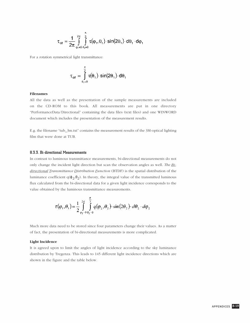
Material Photometric Properties
The rooms are furnished with neutral-coloured desks; walls, ceiling and floor surfaces are
white to medium grey.
Note: τdif =transmittance for hemispherical irradiation;
τ⊥ = transmittance for normal irradiation;
U-value in W/m2K.
Figure 8-4.21:
External view of
the two test rooms

8-38 daylight in buildings
Equipment for Measurement
Sensors used for interior illuminance measurements were two rows of 10 calibrated
sensors BEHA 96408. Exterior illuminance data were collected by sensors mounted on black
honeycomb stitch support (one horizontal LMT/BAP30 FCT, 4 vertical Hagner ELV641, plus
one vertical sensor on each facade). All sensors were connected to a Campbell CR10 data
acquisition system.
8.4.8. Institut für Lichtund Bautechnik (ILB), Germany
Test Room Description
The experimental assessment of daylight systems was carried out in two unfurnished and
unoccupied mock-up offices at the Institute for Light and Building Technique at the
University of Applied Sciences Cologne (ILB), Germany. ILB is located in the centre of
Cologne (latitude 51°N, longitude 7°E). The test rooms are situated on the roof of the
university on the 9th floor.
Geometry
The mock-up offices at ILB consist of 2 rooms with identical geometric measures. The test
rooms face due south with few obstructions. Each room has windows in full height,
but the lower part of the windows were covered during the measurements (sill height is
0.78 m above the interior floor level). The angle of obstruction was 0° during the
measurement period.
Figure 8-4.22:
Internal view of
test room with the
anidolic system

appendices 8-39
Material photometric properties
The rooms are unfurnished with light-coloured surfaces (walls - white, floor - grey, ceiling
- white).
Note: τdif =transmittance for hemispherical irradiation;
τ⊥ = transmittance for normal irradiation;
U-value in W/m2K.
Figure 8-4.23:
Elevations of test
room (above) and
floor plan (below)
8-40 daylight in buildings
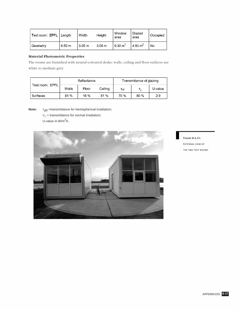
Equipment for Measurement
All sensors used for interior and exterior illuminance measurements were light-sensitive
silicon diodes with V(λ) calibration from PRC Krochmann, Germany. Interior illuminance
levels were measured in a centre line perpendicular to the window (6 sensors) at a work
plane height of 0.85 m. All sensors were connected to a PC-card-based self-developed data
acquisition system. Exterior measurements included global horizontal and shielded vertical
sky (south) illuminance.
Figure 8-4.24:
Exterior view of
test rooms of ILB
(9th
floor)
Figure 8-4.25:
Interior view of test
room with sun-
directing glass in
upper aperture

appendices 8-41
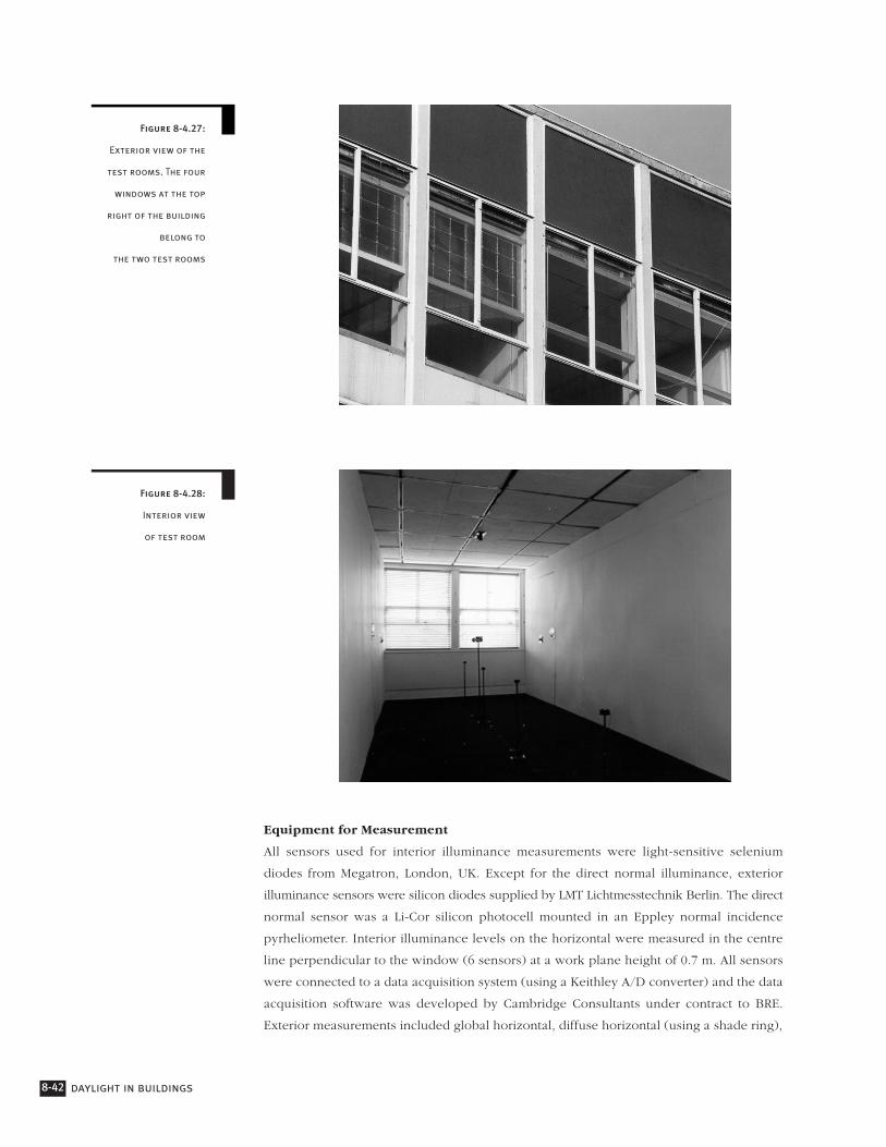
8.4.9. Building Research Establishment (BRE), UK
Test Room Description
The experimental assessment of daylight systems was carried out in two unfurnished mock-
up offices at the Building Research Establishment (BRE). BRE is located in Garston, near
Watford, around 30 km north of London (latitude 51.7°N, longitude 0.4°W).
Geometry
The mock-up offices at BRE consist of 2 rooms of identical area. The test rooms are oriented
around 10° west of due south. Each room has two windows (window head height is 2.6
m and sill-height is 1 m above the interior floor level) and the windows are almost the full
room width, but have extensive glazing bars including a large central pillar. There is a tree
to the east of the rooms, which shades the reference room window before 10:30 AM.
Material Photometric Properties
The rooms are unfurnished with light-coloured surfaces (walls - magnolia, floor - dark
brown, ceiling - white).
Note: τdif =transmittance for hemispherical irradiation;
τ⊥ = transmittance for normal irradiation;
U-value in W/m2K.
1.8m 1.8m 1.8m 1.8m
9 m
3 m
1.2m
0.9m
Plan
Window elevation
Figure 8-4.26:
Plan and window
elevation of
a test room
8-42 daylight in buildings
Equipment for Measurement
All sensors used for interior illuminance measurements were light-sensitive selenium
diodes from Megatron, London, UK. Except for the direct normal illuminance, exterior
illuminance sensors were silicon diodes supplied by LMT Lichtmesstechnik Berlin. The direct
normal sensor was a Li-Cor silicon photocell mounted in an Eppley normal incidence
pyrheliometer. Interior illuminance levels on the horizontal were measured in the centre
line perpendicular to the window (6 sensors) at a work plane height of 0.7 m. All sensors
were connected to a data acquisition system (using a Keithley A/D converter) and the data
acquisition software was developed by Cambridge Consultants under contract to BRE.
Exterior measurements included global horizontal, diffuse horizontal (using a shade ring),
Figure 8-4.27:
Exterior view of the
test rooms. The four
windows at the top
right of the building
belong to
the two test rooms
Figure 8-4.28:
Interior view
of test room

appendices 8-43
direct solar normal (using a solar tracker), and vertical total illuminance in the plane of
the test room window. This was shielded from the ground-reflected light by a black
honeycomb material.
8.4.10. Summary of Monitoring and Data Acquisition Systems
Description of Monitoring Equipment for Measurement
Description of Data Acquisition System

8-44 daylight in buildings
IEA Task 21 Monitoring Procedures for Assessing the Daylighting Performance
of Buildings
Monitoring of daylighting systems and daylight-responsive lighting control systems was
carried out in test rooms in Australia, Austria, Denmark, Finland, France, England, Germany,
the Netherlands, Norway, Switzerland, and the United States. A Monitoring Protocol,
including monitoring procedures, was formulated for these studies; this protocol focuses
on quantifying the performance of the systems evaluated. This appendix summarises the
information that can be found in the IEA SHC Task 21 document “Monitoring Protocol”
(appended to the CD-ROM of this book).
8.5.1. Objectives of the Monitoring Procedures
The objective of the monitoring procedures is to establish a basis for evaluating a
daylighting or lighting control strategy compared to a reference situation in occupied and
unoccupied rooms under real sky conditions. These procedures describe the parameters
to be considered, and give guidance for measurements as well as procedures for user
assessment. Different levels of monitoring are included. The monitoring level selected
depends on the capacities of a test situation, i.e., available measurement equipment, and
the daylighting system or control strategy to be tested. The Monitoring Protocol also
includes recommendations for documentation of testing procedures and evaluation of the
system’s performance compared to a reference situation. This protocol can be used for
studies in standard offices with only vertical window(s) and horizontal work planes.
8.5.2. Approach
Daylighting systems are used to redirect incoming sunlight or skylight to areas where it is
required. Therefore, these systems need to be evaluated for their ability to control daylight
levels and to redirect sunlight and skylight into the perimeter zone of a building under
overcast and clear sky situations. Because a traditional window will often provide non-
uniform daylight distribution, daylighting systems should also be evaluated for their ability
to reduce the large variations in the daylight levels within a room.
Daylight-responsive artificial lighting control systems are generally designed to maintain
an illuminance level set in the tuning procedure. By supplementing daylight when it is
insufficient, these systems save energy. Therefore, illuminance levels on the work plane
and lighting energy consumption both need to be monitored.
The overall performance of a daylighting or control system is determined by the capability
of the system to meet the requirements mentioned above while maintaining visual quality
Monitoring Procedures8.5.

appendices 8-45
in a room. Therefore, visual comfort and other related parameters are included in the
monitoring procedures to assess user acceptance of the room illumination and the installed
system(s). A system’s capability is assessed by comparing a room where the system is
installed to an identical reference room without the system, under the same sky conditions.
Daylighting conditions in the two rooms and exterior conditions are monitored
simultaneously.
The reference room for testing a daylighting system under overcast skies has a double pane
of clear glazing. For clear sky measurements, a shading system that is typical for the region
should be included, e.g., downward-tilted venetian blinds. No artificial lighting is used.
The reference room for testing a daylight-responsive artificial lighting control system is
equipped with existing luminaires that do not have the control system.
8.5.3. Monitoring Procedures
The monitoring procedures have four phases:
• A decision phase, in which choices are made regarding testing and the types of
measurements to be carried out;
• A preparatory phase, in which the unchangeable conditions of the test rooms and
monitoring equipment to be used are recorded in a descriptive document;
• A monitoring programme, which includes procedures for systematically verifying
conditions and sensors; and
Figure 8-5.1:
Basic assumptions for
reference situation

8-46 daylight in buildings
• A conclusion phase, in which the performance of the daylighting systems or
daylight-responsive artificial lighting control system is determined based on the
test results.
Minimum Measurements
Exterior measurements that will provide the minimum basis for evaluating a selected
daylighting system include the horizontal global illuminance and the vertical sky
illuminance. Interior work plane measurements should include those which enable one to
check the system’s ability to increase daylight penetration, provide “uniform” illuminance
distribution, or maintain a certain illuminance level in the room (see, for example Figure
8-5.2). The height of the horizontal work plane should be consistent with the standard in
the country where testing is performed (0.70–0.85 m above floor level).
The location of sensors depends on the number of sensors available and the monitoring
level (minimal or with additional requirements). For monitoring a daylighting system, the
locations will also depend on the daylighting system used. When a daylight-responsive
artificial lighting control system is used, sensor locations depend on window size and
transmittance.
Visual Comfort and User Acceptance
At a minimum, evaluation of visual comfort and user acceptance in a test room situation
consists of observations in the occupied and unoccupied rooms. It includes the detection
of sun patches areas with high luminance and glare.
For a more extensive evaluation of visual comfort and user acceptance, a standard
questionnaire has been developed (see CD-ROM for more detailed monitoring procedures).
When daylighting systems are tested, the questionnaire should include questions on glare
(direct and indirect), illuminance distribution, illuminance levels at the work plane, and
Figure 8-5.2:
Sensor position
for monitoring a
control system

appendices 8-47
questions concerning satisfaction and acceptance of the system. When control systems are
tested, the questionnaire should include questions on illuminance distribution, maintained
illuminance level on the work plane, and questions related to the system.
Duration of Monitoring in Unoccupied Test Rooms
The time period for a minimum evaluation of a daylighting system or a control system is:
One day under overcast sky conditions and three days (winter and summer solstices and
equinox) when the sky is clear.
For overcast sky with ideal CIE sky luminance distribution, one measurement may be
sufficient. However, it is recommended that a full day of measurements be carried out.
Measurements under clear sky conditions should be taken within eight weeks around the
winter and summer solstices and the equinox.
Long-term monitoring is preferable for daylight-responsive artificial lighting control systems,
to establish realistic energy saving potentials.
Additional Measurements For a More Detailed Evaluation
Additional measurements are suggested to monitor system-specific characteristics. Many
daylighting systems are used to redirect daylight. Luminance and illuminance measurements
on walls and ceiling can be used to monitor this ability. Monitoring can also include
supplementary measurements to evaluate a daylighting system’s capability to reduce
discomfort glare.
Analysis of the Results
The performance of a daylighting system should be presented in comparison to the
reference situation. Advantages and disadvantages can be assessed by comparison of
absolute illuminance levels, daylight factors, and daylight distribution. Overall performance
of a system should include assessment of user acceptance of the system.
The performance of daylight-responsive artificial lighting control systems can be expressed
in terms of their capability to control artificial light in response to available daylight, to
maintain the design illuminance level, and to reduce energy consumption. In addition,
monitoring results should show duration, frequency, and magnitude of insufficient light
levels. The overall performance of these systems should include an evaluation of
user acceptance.
8.5.4. Conclusion
Until now, no standard monitoring procedures have been available for assessing and
comparing performances of daylighting systems and daylight-responsive lighting control
systems. The lack of monitoring protocols has been rectified by this documentation of the

8-48 daylight in buildings
performance assessment of selected systems using standard monitoring methods in test
rooms under real sky conditions.
The emphasis in the monitoring procedures used in the evaluation of daylighting and
daylight-responsive control systems in IEA SHC Task 21 was on effective daylight utilisation,
electrical energy savings, and user acceptance. These monitoring procedures have been
proven to be effective; therefore they are a valuable method for future evaluations to
determine system performance. The complete monitoring procedures are included in the
CD-ROM appended to this book.

appendices 8-49
Prismatic Elements
3M (Scotch Optical Lighting Film)
3M Center Bldg. 225-2N06
St. Paul, MN 55144-1000
United States
Tel. +1 (612) 733-1898
Fax +1 (612) 736-3893
Prismatic film, light pipes,
mirror film
Siteco (formerly Siemens)
Beleuchtungsstarke GmbH
Ohmstrasse 50
83301 Traunreut
Germany
Tel. +49 8669 331
Fax +49 8669 33684
Prismatic glazing, mirrored
louvers, eggcrate microlouver,
reflective ceilings
Yazaki Co. Ltd.
1370 Koyasu-cho
Hamamatsu-shi
Shizuoka 435
Japan
Tel. +81 534-61-7111
Prismatic glazing
Bartenbach Lichtlabor
Rinner Str. 14
6071 Aldrans/Innsbruck
Austria
Tel. +43 512 386810
Fax +43 512 378048
Prismatic panels, louver and
blinds, light shelves
Redbus Serraglaze
3 The Quadrant
Coventry CV1 2DY
United Kingdom
Tel. +44 1203 243621
Fax +44 1203 243622
Stacked reflector/refractor
array prismatic sheet
Manufacturers of Products 8.6.

8-50 daylight in buildings
Holographic Optical Elements
Institut fur Licht-und Bautechnik
an der Fachhochschule Köln
Gremberger Straße 151a
50679 Köln
Germany
Tel. +49 221 831096
Fax +49 221 835513
Holographic glazing, transparent
shading systems, light-guiding glass
Autotype Limited
Grove Road
Wantage Oxfordshire
OX12 9BZ
United Kingdom
Tel. +44 1235 767777
Fax +44 1235 771196
Holographic glazing
Louvers and Blinds
Altasol Ltd.
18 Gilmour Street
Burwood, Victoria 3125
Australia
Reflective louvres
Colt International Limited
New Lane
Havant, Hampshire PO9 2LY
United Kingdom
Tel. +44 1705 451111
Fax +44 1705 454220
Moveable louvers
SEA Corporation
2010 Fortune Drive, Suite 102
San Jose, CA 95131,
United States
Tel. +1 (408) 954-1250
Fax +1 (408) 954-1254
Advanced Environmental
Research Group
3681 S Lagoon View Drive
Greenbank, WA 98253
United States
Tel. +1 (206) 678 5439
Fax +1 (206) 678 5439
Holographic glazing
Seele GmbH & Co KG
Gutenbergstraße 19
86368 Gersthofen
Germany
Tel. +49 821 2494 0
Fax +49 821 2494 100
Transparent shading
Okalux Kapillarglas GmbH
Am Jöspershecklein
97828 Marktheidenfeld-Altfeld
Germany
Tel. +49 93 91 10 41
Fax +49 93 91 68 14
Hallmark Blinds Ltd
173 Caledonian Road
Barnsbury
London N1 0SL
United Kingdom
Tel +44 207 837 0964/8181
Fax +44 207 833 1693
Synertech Systems Corporation
472 South Salina St. Suite 800
Syracuse, NY 13202
United States
Tel. +1 (315) 422-3828
Daylight microlouvers

appendices 8-51
Hunter Douglas Limited
Mersey Industrial Estate
Heaton Mersey, Stockport
Cheshire SK4 3EQ
United Kingdom
Tel. +44 161 432 5303
Fax +44 161 431 5087
Reflective blinds
WAREMA Renkhoff GmbH
Vorderbergstraße 30
97828 Marktheidenfeld
Germany
Tel. +49 9391 20600
Fax +49 9391 20279
F Muller Pty Ltd.
16 St Albans Road
Kingsgrove, NSW 2208
Australia
Tel. +61 5022633
GlasTec
Rosenheimer Glastechnik GmbH
Neue Straße 9
Stephanskirchen
Germany
Tel. +49 8031 73145
Fax +49 8031 73243
Baumann-Hüppe AG
Zugerstrasse 162
Postfach 100
8820 Wädenswyl
Switzerland
Tel. +41 1 782 5111
Fax +41 1 782 5204
Huppe Form GmbH
Sonnenschutz und Raumsysteme
Postfach 252326015 Oldenburg
Germany
Tel. +49 441 402282
Fax +49 441 402 454
Reflective blinds
Glas Schuler GmbH & Co.KG
Ziegelstraße 23-25
91126 Rednitzhembach
Germany
Tel. +49 9122 / 7046
Fax +49 9122 70515
Dasolas Internat.
Productions
A/S Moegelgaardsvej 9-13
8529 Lystrup
Denmark
Brüder Eckelt + Co
Glastechnikgesellschaft mbH
Resthofstr. 18
4400
Austria
Tel.: +43 (7252) 894-0
Fax +43 (7252) 894-24

8-52 daylight in buildings
Heliostats
Bomin Solar
Industriestrasse 8-10
79541 Lörrach
Germany
Tel. +49 7621 95960
Fax +49 7621 54368
Heliostats, mirrors, prisms, lenses
La Forêt Engineering &
Information Service Co. Ltd.,
Himawari Building,
Toranomon 2-7-8
Minato-ku, Tokyo 105, Japan
Tel. +81 3 3593 0091
Fax +81 3 3593 0095
Himawari (heliostat and fibre optic)
Sumitomo Corporation
444 South Flower St.
Los Angeles, CA 90071-2975
United States
Tel. +1 (213) 489-0371
Fax +1 (213) 489-0300
Himawari (heliostats and fibre optics)
EGIS GmbH
Flutstr. 34-36
63071 Offenbach/Main
Germany
Tel. +49 (69) 85 83 27
Fax +49 (69) 85 78 63
Light Pipes
The Sun Pipe Company
PO Box 2223
Northbrook, IL 60065
United States
Tel. +1 (800) 8444786
Fax +1 (708) 272 6972
Light pipes
Alternate Energy Institute
5333 Mission Center Rd. No. 351
San Diego, CA 92108
United States
Tel. +1 (619) 692-2015
Heliostats
Solartech
A. Kuzelka
Heugasse 8/1
2344 Maria Enzersdorf
Austria
Tel. 0664 481 14 12
Double mirror heliostat
Zentrum für Sonnenenergie- und
Wasserstofforschung
Hessbruhlstrase 2lc
70565 Stuttgart
Germany
Tel. +49 (711) 7870 222
Thermohydraulic heliostat
Schlaich Bergermann & Partner
Stuttgart
Germany
Tel. +49 711 64 87 10
Solartube Ltd.
5825 Avenida Enchinas, Suite 101
Carlsbad, CA 92008
United States
Tel. +1 (619) 929 6060
Light pipes

appendices 8-53
Monodraught Limited
6 Lancaster Court
Cressex Business Park
High Wycombe, Bucks HP12 3TD
United Kingdom
Tel. +44 1494 464858
Fax +44 1494 532465
Light pipes
Sanyo Electric Co. Ltd.
Air Conditioning and Refrigeration
Development Center
180 Sakata Oizumi-machi, Ora-gun
Gunma, Japan
Tel. +81 (276) 618122
Fax +81 (276) 618802
Double prism heliostats, light pipes
Skydome Ltd.
Unit 21
Springtown Industrial Estate
Springtown, Londonderry BT 46 OLY
United Kingdom
Tel. +44 1504 370270
Fax +44 1504 373411
Corrugated light pipe systems
Laser-Cut Panels
Department of Physics
(Dr I Edmonds, Dr I Cowling)
Queensland University of Technology
GPO Box 2434
Brisbane Q 4001
Australia
Tel. +61 7 864 2329
Fax +61 7 864 1521
Laser-cut light deflecting sheets, stacked
curved daylight deflecting prisms
LTI Lichttechnik
Heiko Schnetz GmbH
Konrad-Adenauer-Str. 25
50996 Köln
Germany
Tel. +49 221 35099 70
Fax +49 221 35099 71
LGM & Associates
PO Box 2613
Northbrook, IL 60062
United States
Tel. +1 (708) 272-6977
Light pipes
INGLAS - Innovative
Glassysteme GmbH & Co. KG
Im Winkel 4/1
88048 Friedrichshafen
Germany
Tel. +49 7544 6547 - 23
Special glazings
Skydome Skylight Systems Ltd
39 Antimony Street
Carole Park QLD 4300
PO Box 154 Goodna QLD 43400
Australia
Tel. 61 7 3271 3200
Fax 61 7 3271 4481
Angular selective skylights
Anidolic Systems
Solar Energy and
Building Physics
Laboratory (LESO-PB)
Swiss Federal
Institute of Technology
in Lausanne (EPFL)
1015 Lausanne
Switzerland
Tel. +41 21 693 45 45
Fax +41 21 693 27 22
Anidolic systems
Synergetics Inc.
122 Cox Avenue
Raleigh, NC 27605
United States
Tel. +1 (919) 832 4011
Variable area light
reflecting assembly
Felix Constructions SA
Route de Renens 1
1030 Bussigny-Lausanne
Switzerland
Tel. +41 21 701 0441
Fax +41 21 701 31 68
Facade integrated
Anidolic systems
8-54 daylight in buildings