Embed Size (px)
Citation preview
Apparatus for Vacuum Heating of TEM Samples
Adam Callens
Capstone Project, Physics 492R May 1, 2007
Advisor: Richard Vanfleet
Abstract The purpose of this capstone project was to create a sample holder to serve
several purposes. A sample holder was created that can be put into the specified vacuum
chamber. Additionally, the sample holder is capable of holding samples less than three
millimeters in diameter and larger than 2 millimeters in diameter. The sample holder also
proved capable of heating the samples to a sustained temperature of 120C or more. This
project has been a success and has met its goals.
ii
Table of Contents
Introduction........................................................................................................................ iv Methods .............................................................................................................................. 1 Mathematical Model of the Heating Process...................................................................... 8 Results............................................................................................................................... 11 Conclusions....................................................................................................................... 11 Acknowledgements........................................................................................................... 12
iii
Table of Figures Figure 1: Exploded view of the entire assembly-------------------------------------------------2 Figure 2: Disk with four holes ---------------------------------------------------------------------3 Figure 3: Cap with 3 holes for screws------------------------------------------------------------3 Figure 4: Aluminum block--------------------------------------------------------------------------4 Figure 5: Collapsed view of entire assembly ----------------------------------------------------5 Figure 6: Engineering drawings ------------------------------------------------------------------5 Figure 7: Aluminum block with zirconium and Teflon sealant --------------------------------7
iv

Introduction:
This capstone project has resulted in the creation of a sample holder that both
holds and heats a sample inside a vacuum system, in preparation for Transmission
Electron Microscopy (TEM) analysis. The results of TEM analysis can be greatly skewed
if there are any foreign molecules on the surface of the sample to be studied. The sample
holder will allow samples to be properly cleaned prior to being analyzed.
Methods: The first step in this process was to evaluate the needs of the overall project. The
sample holder is required to fit inside of a vacuum chamber. The vacuum chamber
provides a near-zero pressure environment (10e-7 mbar) for heating and cleaning the
sample. Heating the sample while in a vacuum allows contaminates (typically light
hydrocarbon molecules) to easily be jettisoned from the surface of the sample. Therefore,
it is critical that the sample holder conforms to the vacuum chamber geometry and creates
a seal to maintain the vacuum.
While not in use, the opening into the vacuum chamber is closed with a nylon
plug. This plug serves as the model for the design of the sample holder. The exact
dimensions necessary are taken and used to configure the sample holder. This is a
meticulous process because of the required tolerances of the system.
The preliminary drawings were prepared using the measurements from the nylon
plug model. There were numerous changes to these initial drawings as the design process
progressed although the general configuration remained unchanged. We began with the
exterior geometry and designed this to meet the requirements for ease of insertion into the
vacuum chamber. We added a hole running the length of the entire sample holder. We
1
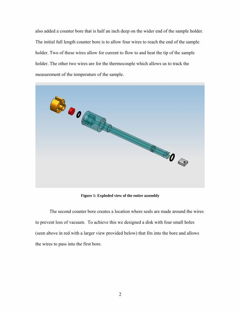
also added a counter bore that is half an inch deep on the wider end of the sample holder.
The initial full length counter bore is to allow four wires to reach the end of the sample
holder. Two of these wires allow for current to flow to and heat the tip of the sample
holder. The other two wires are for the thermocouple which allows us to track the
measurement of the temperature of the sample.
Figure 1: Exploded view of the entire assembly
The second counter bore creates a location where seals are made around the wires
to prevent loss of vacuum. To achieve this we designed a disk with four small holes
(seen above in red with a larger view provided below) that fits into the bore and allows
the wires to pass into the first bore.
2
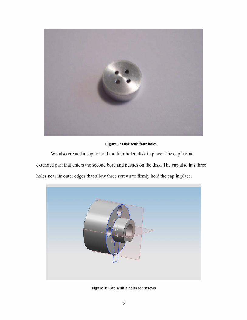
Figure 2: Disk with four holes
We also created a cap to hold the four holed disk in place. The cap has an
extended part that enters the second bore and pushes on the disk. The cap also has three
holes near its outer edges that allow three screws to firmly hold the cap in place.
Figure 3: Cap with 3 holes for screws
3
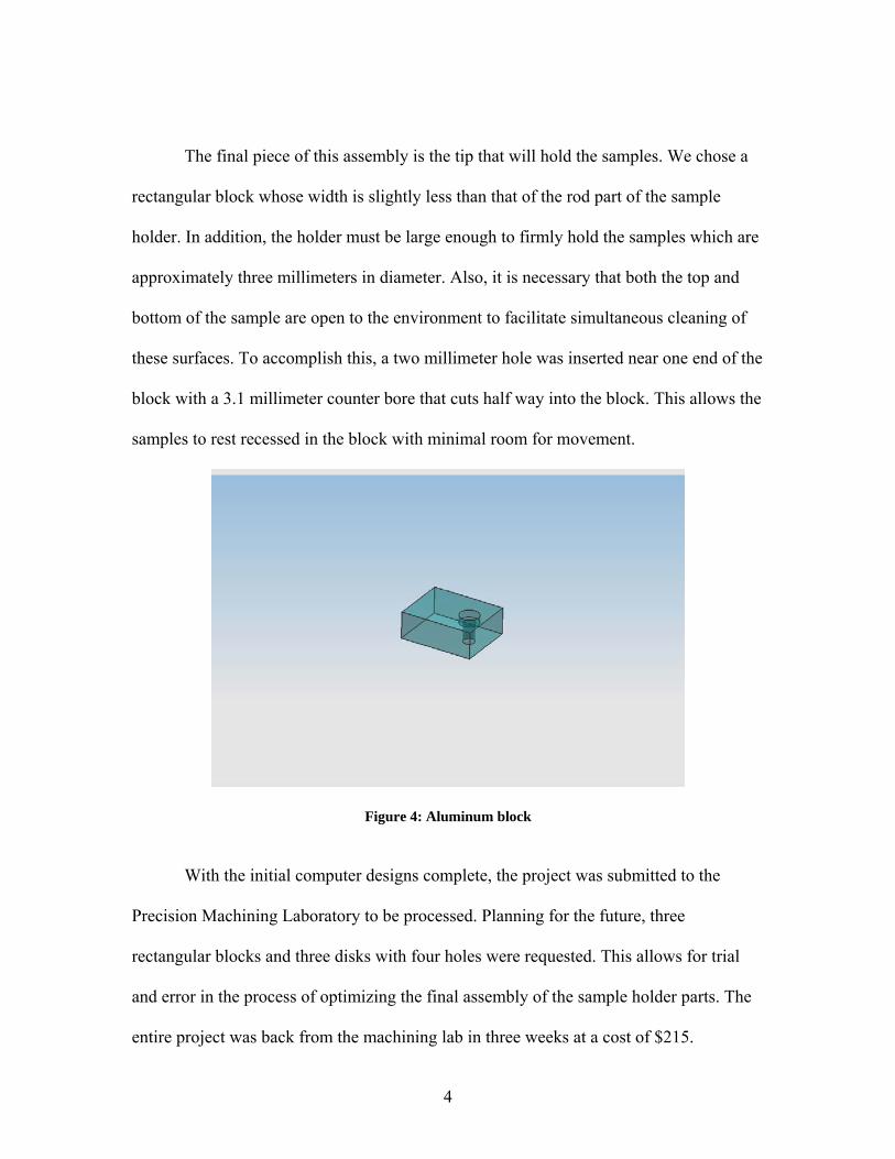
The final piece of this assembly is the tip that will hold the samples. We chose a
rectangular block whose width is slightly less than that of the rod part of the sample
holder. In addition, the holder must be large enough to firmly hold the samples which are
approximately three millimeters in diameter. Also, it is necessary that both the top and
bottom of the sample are open to the environment to facilitate simultaneous cleaning of
these surfaces. To accomplish this, a two millimeter hole was inserted near one end of the
block with a 3.1 millimeter counter bore that cuts half way into the block. This allows the
samples to rest recessed in the block with minimal room for movement.
Figure 4: Aluminum block
With the initial computer designs complete, the project was submitted to the
Precision Machining Laboratory to be processed. Planning for the future, three
rectangular blocks and three disks with four holes were requested. This allows for trial
and error in the process of optimizing the final assembly of the sample holder parts. The
entire project was back from the machining lab in three weeks at a cost of $215.
4
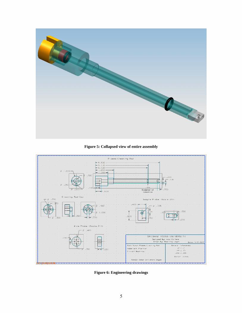
Figure 5: Collapsed view of entire assembly
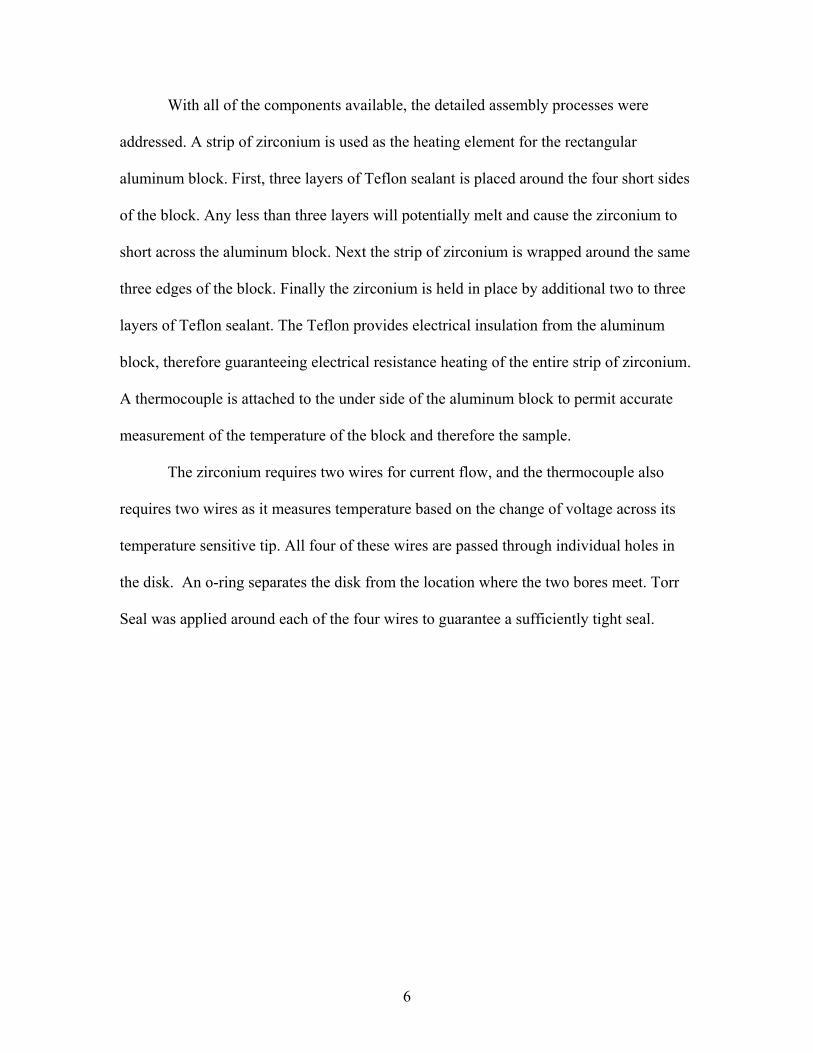
Figure 6: Engineering drawings
5
With all of the components available, the detailed assembly processes were
addressed. A strip of zirconium is used as the heating element for the rectangular
aluminum block. First, three layers of Teflon sealant is placed around the four short sides
of the block. Any less than three layers will potentially melt and cause the zirconium to
short across the aluminum block. Next the strip of zirconium is wrapped around the same
three edges of the block. Finally the zirconium is held in place by additional two to three
layers of Teflon sealant. The Teflon provides electrical insulation from the aluminum
block, therefore guaranteeing electrical resistance heating of the entire strip of zirconium.
A thermocouple is attached to the under side of the aluminum block to permit accurate
measurement of the temperature of the block and therefore the sample.
The zirconium requires two wires for current flow, and the thermocouple also
requires two wires as it measures temperature based on the change of voltage across its
temperature sensitive tip. All four of these wires are passed through individual holes in
the disk. An o-ring separates the disk from the location where the two bores meet. Torr
Seal was applied around each of the four wires to guarantee a sufficiently tight seal.
6
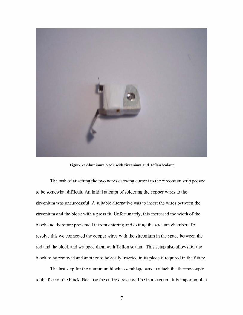
Figure 7: Aluminum block with zirconium and Teflon sealant
The task of attaching the two wires carrying current to the zirconium strip proved
to be somewhat difficult. An initial attempt of soldering the copper wires to the
zirconium was unsuccessful. A suitable alternative was to insert the wires between the
zirconium and the block with a press fit. Unfortunately, this increased the width of the
block and therefore prevented it from entering and exiting the vacuum chamber. To
resolve this we connected the copper wires with the zirconium in the space between the
rod and the block and wrapped them with Teflon sealant. This setup also allows for the
block to be removed and another to be easily inserted in its place if required in the future
The last step for the aluminum block assemblage was to attach the thermocouple
to the face of the block. Because the entire device will be in a vacuum, it is important that
7
the thermocouple be in direct contact with the block in order to accurately measure the
block temperature. Special heat resistant tape was used to hold the thermocouple to the
block. Additionally, the tape provides greater stability to the block by restricting its range
of motion. With the block now attached, the cap was put in place and the three screws
tightened in preparation for testing the heating and vacuum holding capabilities of the
sample holder.
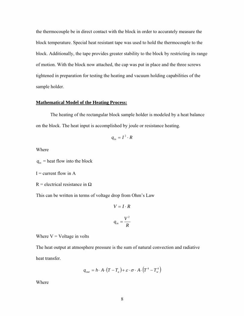
Mathematical Model of the Heating Process: The heating of the rectangular block sample holder is modeled by a heat balance
on the block. The heat input is accomplished by joule or resistance heating.
RIqin ⋅= 2
Where
inq = heat flow into the block
I = current flow in A
R = electrical resistance in Ω
This can be written in terms of voltage drop from Ohm’s Law
RIV ⋅=
RVqin
2
=
Where V = Voltage in volts
The heat output at atmosphere pressure is the sum of natural convection and radiative
heat transfer.
( ) ( )44waout TTATTAhq −⋅⋅⋅+−⋅⋅= σε
Where
8
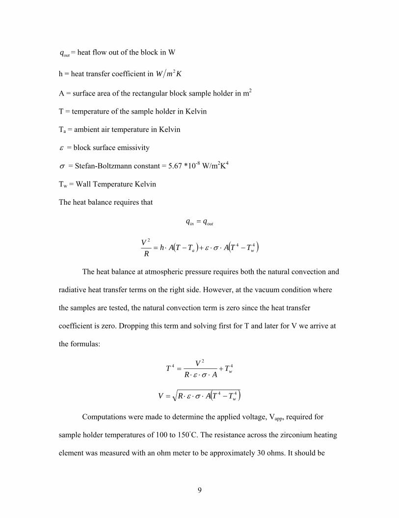
outq = heat flow out of the block in W
h = heat transfer coefficient in KmW 2
A = surface area of the rectangular block sample holder in m2
T = temperature of the sample holder in Kelvin
Ta = ambient air temperature in Kelvin
ε = block surface emissivity
σ = Stefan-Boltzmann constant = 5.67 *10-8 W/m2K4
Tw = Wall Temperature Kelvin
The heat balance requires that
outin qq =
( ) ( )442
wa TTATTAhR
V−⋅⋅+−⋅= σε
The heat balance at atmospheric pressure requires both the natural convection and
radiative heat transfer terms on the right side. However, at the vacuum condition where
the samples are tested, the natural convection term is zero since the heat transfer
coefficient is zero. Dropping this term and solving first for T and later for V we arrive at
the formulas:
42
4wT
ARVT +
⋅⋅⋅=
σε
( )44wTTARV −⋅⋅⋅= σε
Computations were made to determine the applied voltage, Vapp, required for
sample holder temperatures of 100 to 150C. The resistance across the zirconium heating
element was measured with an ohm meter to be approximately 30 ohms. It should be
9
noted for future research that the resistance measured varied between 25 and 40 ohms but
consistently hung around 30 ohms. This is possibly error of the ohm meter. The
emissivity was assumed to be one and the wall temperature was taken to be equal to the
ambient temperature of 295 K (22C). The surface area of the holder was calculated to be
0.000365 m2. The applied voltage was related to the calculated voltage drop across the
zirconium heating element from calibration measurements at atmospheric conditions.
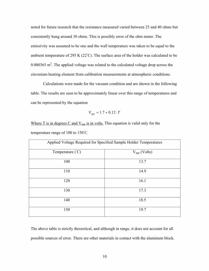
Calculations were made for the vacuum condition and are shown in the following
table. The results are seen to be approximately linear over this range of temperatures and
can be represented by the equation
TVapp ⋅+= 12.07.1
Where T is in degrees C and Vapp is in volts. This equation is valid only for the
temperature range of 100 to 150C.
Applied Voltage Required for Specified Sample Holder Temperatures
Temperature (C) Vapp (Volts)
100 13.7
110 14.9
120 16.1
130 17.3
140 18.5
150 19.7
The above table is strictly theoretical, and although in range, it does not account for all
possible sources of error. There are other materials in contact with the aluminum block.
10
The Teflon sealant is present on the block as well as the copper wires that are in direct
contact with the zirconium strip. Heat is conducted along the copper wires themselves
and in our formula this has been neglected.
Results: Before testing the sample holder, a control test was conducted by setting the
vacuum chamber to atmospheric pressure and timing how long it takes for it to pump
down to high vacuum with the nylon plug in place. This baseline process was
accomplished in two minutes. This test was repeated twice with the nylon plug replaced
by the assembled sample holder. In both tests the vacuum chamber reached high vacuum
at a few seconds under two minutes. This is consistent with the time required using the
nylon plug. Therefore, it was demonstrated that the sample holder is able to both establish
and hold the vacuum necessary for performing the required task.
Two nine volt batteries in series were attached to the zirconium strip. Heat
balance calculations had shown that the approximately 18 volts that are produced will
bring the sample holder near 125 °C. The target temperature for the actual sample
cleaning runs is between 120 and 150 °C. The test of the sample at eighteen volts resulted
in a measured temperature of 123 °C. Therefore, the test demonstrated that the applied
voltage placed the sample holder within the range for optimal cleaning as predicted by
the heat balance calculations.
Conclusions: This project has been met with great success. We have been able to achieve all of
the original objectives. First we are able to both create and hold a high vacuum with the
11
plasma cleaner while the sample holder is inserted. This is crucial to being able to clean
samples and prepare them for TEM analysis. Second, we are able to produce the
necessary temperatures to cause contaminates to separate and be removed from the
surface of samples. Both of these are crucial and therefore central to the completion of
this project.
There remain opportunities for anyone wishing to make additions to this project in
the future. Superior methods for attaching the end block to the rod would allow for
greater stability and perhaps the opportunity to easily interchange blocks. A helpful
addition would be the ability to lock a sample in place using a spring loaded clasp.
Additionally, it would be beneficial to have a variable power source. One that uses
current from a wall socket would remove batteries from the equation and therefore reduce
the cost of operation. This would also allow for a great range of temperatures to be met in
the case of unique samples with unique requirements. Along with a variable power
source, the creation of a chart by experimentation comparing voltages with sustained
temperatures would prove valuable.
Acknowledgements: I would like to thank Dr.Vanfleet for his patience and willingness to work with
me. He has been very helpful by always providing his time and ideas when needed. I
would also like to thank Sterling Logan for his assistance in creating the engineering and
3-D drawings. Without his help this would have taken much longer and lacked its high
level of professionalism. The Precision Machining Lab provided excellent results from
12

the drawings that they were provided. I would especially like to thank my father, Dr.
Gene Callens, for giving me that extra push at the end.
13