Embed Size (px)
Citation preview
Utah Fire Service Certification System
APPARATUS DRIVER / OPERATOR PUMPER
CERTIFICATION STANDARD
NOVEMBER 2018
ii
Utah Fire Service Certification Council
Chairperson Scott Spencer, Chief
Payson Fire Department
Vice-Chairperson Paul Bedont, Chief
Price Fire Department
Council Members
Don Adams, Fire Marshal Jason Earl, Deputy Chief Wayne County Orem Fire Department Jeremy Raymond, Chief/Director Wade Snyder, Asst Fire Mgmt. Officer Uintah Fire Suppression SSD Division of Forestry, Fire & State Lands Merlin Spendlove, Battalion Chief Craig Stanley, Firefighter Hurricane Fire & Rescue Blanding Fire Department Ray Stokes, Firefighter Rod “Hoss” Tomkinson, Captain ATK Fire Department Logan Fire Department Christopher Trevino, Battalion Chief David Youngberg, Battalion Chief West Jordan Fire Department North Davis Fire District
Utah Fire & Rescue Academy Staff
Director Brad Wardle
Program Manager Lori Howes
Certification Specialists Jennifer Lindley Marta Morrow
Hilary Kline
For questions or comments concerning this or other Utah certification standards contact: Utah Fire Service Certification Council
Utah Fire & Rescue Academy Utah Valley University
3131 Mike Jense Parkway Provo, Utah 84601
Toll-Free # 1-888-548-7816 FAX # 801-374-0681 www.uvu.edu/ufra
iii
Apparatus Driver/Operator Pumper
Technical Committee
The Certification Council would like to recognize and extend a voice of appreciation to the following fire service professionals for their work on the ADO - Pumper certification standard. These individuals devoted many hours to reviewing the National Fire Protection Association (NFPA) 1002 standard, Certification Test Bank, curriculum text books, and developing the skills for this standard.
Thank You…
Jason Earl, Deputy Chief Orem Fire Department UFSCC Representative Adam Archuleta, Captain Salt Lake City Fire Department Robert Stanley, Captain Lehi Fire Department Dan Cazier, Captain St. George Fire Department Paul Koetitz, Engineer Salt Lake City Fire Department
iv
TABLE OF CONTENTS
Introduction ........................................................................................................................ 1
Certification Requirements for ADO-Pumper Entrance Requirements ....................................................................................................................... 2 Physical Fitness Requirements............................................................................................................ 2 Additional Requirements .................................................................................................................... 3 Department Training Officers ............................................................................................................. 3
Department Training Written Objectives .............................................................................................................................. 4 Manipulative Objectives ..................................................................................................................... 4 Department Training Records ............................................................................................................. 5 Department “In-house” Manipulative Skill Exam .............................................................................. 5
Certification Examinations Written .............................................................................................................................................. 6 Manipulative Skills “Spot Check” ..................................................................................................... 6
ADO-Pumper Certification Prerequisites for Certification ............................................................................................................. 8 Re-certification ................................................................................................................................... 8
ADO-Pumper Certification Checklist ............................................................................................... 9
ADO-Pumper Manipulative Skill Objectives Preventive Maintenance ...................................................................................................................... 10 Driving Operations ............................................................................................................................. 12 Pumping Operations ........................................................................................................................... 15 Appendix A - Training Record ADO-Pumper Training Record ........................................................................................................... 21
Appendix B - Weekly Vehicle Report Weekly Emergency Vehicle Report .................................................................................................... 23
Appendix C - Driving Skills Diagrams / Instructions Alley Dock .......................................................................................................................................... 26 Serpentine ........................................................................................................................................... 27 Diminishing Clearance........................................................................................................................ 28 Confined Space Turnaround ............................................................................................................... 29
Appendix D - Fire Flow Formulas ...................................................................................................... 31
Appendix E - Relay Chart ..................................................................................................................... 36
Appendix F - In-Take Hose Drafting Chart ................................................................................... 39
Appendix G - 7-Step Brake System Guide ...................................................................................... 41
Appendix H – In-House Proctor Instructions Instructions for “In-House” Comprehensive Examination ................................................................ 43
Appendix I - Certification Forms Intent to Participate ............................................................................................................................. 45 Request for Examination ..................................................................................................................... 46 Request for Certification/Re-certification ........................................................................................... 48
1
INTRODUCTION
In Memoriam, September 11, 2001
The world we live in is changing so fast, and the many phases of the fire service are becoming so technical and complex that fire service training must be utilized to its maximum potential. Any overlap, fragmentation, and lack of basic structure must be eliminated. Standardization is the natural complement and necessity. The fire service in Utah, through a state certification program, can meet the needs of future growth and establish uniformity by certification. We will then have more effective and efficient utilization of resources so as to provide the best possible fire protection service for all the citizens throughout the state of Utah. The following certification requirements are based on the objectives listed in the National Fire Protection Association (NFPA) 1002 standard for Fire Apparatus Driver/Operator Professional Qualifications, 2017 Edition, Chapter 5, as verified and adopted by the Utah Fire Service Certification Council (UFSCC). Through these national standards and certification, firefighters and fire departments have a tool to measure specific levels of skills, abilities and knowledge. The UFSCC believes that by participating in the certification program firefighters and fire departments will be better prepared to provide quality life safety and fire protection for their communities. We pay tribute to the 343 members of FDNY who gave their lives to save civilian victims on September 11, 2001, at the World Trade Center. They are true American heroes in death, but they were also American heroes in life. We will keep them in our memory and in our hearts. They are the embodiment of courage, bravery, and dedication. May they rest in peace.
2
CERTIFICATION REQUIREMENTS
Entrance Requirements
Physical Fitness Requirements
In order to certify within the Utah Apparatus Driver Operator (ADO) - Pumper Apparatus program, departments/firefighters must fulfill the following requirements:
1- Complete entrance requirements. 2- Meet pre-requisite, certified Firefighter I, Hazardous
Materials Awareness, Hazardous Materials Operations with UFSCC.
3- Set up and maintain department records. 4- Train on the required written and practical objectives. 5- Pass a department "In House" practical skills examination. 6- Meet any other training requirements/prerequisites as defined
by the certification Council. 7- Pass both written and practical skills examination
administered by the certification Council. 8- Request ADO-Pumper certification. 9- Request re-certification. The UFSCC acknowledges the importance of and need for entrance requirements as listed in the NFPA 1001 standard on Firefighter Professional Qualifications. Many agencies and departments have existing policies, regulations, etc. already in place regarding these requirements. The handling of entrance requirements is a LOCAL MATTER, outside the authority and jurisdiction of the UFSCC. The Council will not check, test, evaluate or determine how individual agencies meet these requirements. Some departments have found it necessary to waive any type of entrance requirements due to their own special needs. Since this is a local decision, this is permitted. However, due to the amount of physical, mental and emotional stress inherent in this profession. The Utah Fire Service Certification Council strongly recommends very careful evaluation before altering or doing away with any entrance requirements. The requirements listed in NFPA 1001, 2013 ed., Chapter 4 are:
1- Meet the minimum educational requirements established by the authority having jurisdiction.
2- The Utah Fire Service Certification Council Policy 11.3
requires that a candidate must be 18 years of age to test and be certified.
3. Meet the medical requirements of NFPA 1582, Standard on Comprehensive Occupational Medical Program for Fire Departments, chapter 5, subsection 5.1.1, as determined by the medical authority of the AHJ. 4. Physical fitness requirements for entry-level personnel shall be developed and validated by the authority having jurisdiction. Physical fitness requirements shall be in compliance with applicable Equal Employment Opportunity regulations and other legal requirements.
3
Additional Requirements
Department Training
Officers
In addition, NFPA 1002 standard for Fire Apparatus Driver/Operator Professional Qualifications, 2017 edition lists the following general requirements:
1- The Fire Apparatus Driver/Operator shall be licensed to drive
all vehicles they are expected to operate in accordance with Utah State law.
2- The Fire Apparatus Driver/Operator shall be subject to
periodic medical evaluations, as required by NFPA 1500 standard on Fire Department Occupational Safety and Health Program, Section 8-1, Medical requirements, to determine that the driver / operator is medically fit to perform the duties of a Fire Apparatus Driver/Operator (NFPA 1002, 1.4.2).
In order for a department to enroll in the certification process, it is necessary for the department to assign training officers. It is recommended that the department assign at least two personnel as training officers to coordinate and provide certification training. Department training officers shall be state certified at the level they are teaching. In addition, the certification Council strongly recommends that training officer be state certified as a Fire Service Instructor I. Department training officers will be responsible for certification training. Their primary responsibility will be to teach, evaluate, and in-house test department personnel on the manipulative skill requirements for each level of certification training. Departments who do not have certified personnel to act as training officers for certification training should contact the Utah Fire and Rescue Academy at (801) 863-7700 or 1-888-548-7816 for assistance in setting up and monitoring certification training.
The final entrance requirement is to complete the "Intent to Participate" form provided in Appendix F and return it to the certification Council. Remember, participation in the certification process is VOLUNTARY. Once you have enrolled, you can withdraw if desired. If a department is already participating in the Utah Fire Service Certification System, it will not be necessary to file another “Intent To Participate” form.
4
DEPARTMENT TRAINING
Written Objectives
Manipulative Objectives
The position of an Apparatus/Driver is one that requires a high level of skill and knowledge. The training that is given to and received by ADO candidates should be of the highest quality and degree. All training received must meet the requirements of NFPA 1002; Chapter 5 (2017 edition) and the skills as approved by the UFSCC contained within the Utah standard. All training received must be documented and recorded on a training record (Appendix A). All testing for ADO-Pumper will be conducted following the policies and procedures of the UFSCC. Training for ADO-Pumper is conducted at the department level or could be received through a joint training agreement between departments on a regional level. Regardless of where the training is received it must prepare the candidate to be a competent and effective apparatus operator. The course material should be referenced to the following textbook to prepare the candidate to successfully pass the state certification examination. A comprehensive list of hydraulic information is found in Appendix D of this standard. These formulas are used on the written examination and will be available during the written examination. Written objectives for ADO-Pumper Apparatus are covered in the following text:
• IFSTA, Pumping and Aerial Apparatus Driver/Operator Handbook, 3rd Edition, 1st Printing
• NFPA 1002, Standard on Fire Apparatus Drive/Operator Professional Qualifications, 2017 Edition.
• NFPA 1500, Fire Department Occupational Safety and Health.
These textbooks are available from various fire service bookstores. A current list of IFSTA textbook sources is available by calling the certification office at 1-888-548-7816. There are numerous methods departments have used to help prepare their personnel for the written examination. Considering the high level of skill and knowledge that is required of an Apparatus Driver Operator, the Council recommends that the candidate participates in a comprehensive class and receive instruction on both manipulative and written requirements. Each of the manipulative skill objectives shall be completed swiftly, safely and with competence as defined below: • Swiftly - Each manipulative skill objective must be completed
within the allotted time.

5
Department Training Record
Department "In House"
Manipulative Skills Examination
• Safely - Each manipulative skill objective must be completed safely. Conduct that could injure an individual or damage equipment is unacceptable. Equipment should be checked prior to skill testing or training to see that it is safe and functional.
• Competence - Each manipulative skill objective is performed
in accordance with the Utah standard. This includes performing the proper steps in sequence. Competence will be measured in accordance with the UFSCS manipulative skill objectives.
Each participant shall have a current training record on file with the department which indicates that he/she has trained on all manipulative skill objectives. Training records must have the date and Instructors original signature and/or initials for each line. Departments may set up their own training records or use the one provided in Appendix A. At the completion of the department's manipulative skills training, the department is required to hold an "in-house" skills examination for the level being trained. This is a comprehensive "in house" skill test conducted by the department training officers. This test is to ensure that skill mastery has been maintained from the beginning to the end of the training process, and to prepare participants for the state examination. Training officers may utilize other personnel to assist in administering the exam; however, they must be certified at the level they are in-house testing. Proctor instructions for the examination are in Appendix E. In-house testers shall follow the proctor instruction sheet to provide for uniformity and fairness during the exam. It is recommended that participants be given two attempts at any skill. If they fail on the second try, then they have failed the evaluation and are required to go through additional training by the department trainer. No training, teaching, or coaching is allowed during the test. After the evaluation, using the test to teach and train is recommended. If manipulative skill weaknesses are evident, the department should conduct additional training and hold a new department "in house" manipulative skill examination to ensure their personnel has fully mastered all required skills. Only those individuals who successfully pass the department skill test will be allowed to participate in the certification council's manipulative skill "spot check" examination. Department records must show that all participants have successfully passed the "in-house" exam.

6
CERTIFICATION EXAMINATIONS
Written Examinations
Manipulative Skills “Spot Check”
Examination
After completion of the training process, the Chief/Administrator can request testing for the candidate using the "Request for Examination” form in Appendix F. The candidate will then have three attempts to pass the written examination. A separate application must be sent to the Certification Council for each attempt. Request forms must reach the Certification Council no later than 30 days prior to the examination date. The entire examination process must be completed within one year of the first written exam date. The written examination is a randomly generated 100-question test covering the written objectives of the ADO - Pumper Apparatus standard. This is a closed book test. Calculators are allowed on the written exam and will be provided by the Certification office. No other calculators will be allowed. The comprehensive list of fire flow formulas provided in Appendix D will be allowed for use during the written examination and will provided for by the Certification Tester. A minimum score of 70% is required to pass the certification exam. Firefighters failing the first attempt of the written exam will be permitted to retest no sooner than 30 days from the date of the last exam. Three attempts are given to pass the exam. If a participant fails the written examination three times, he/she has failed the certification process and must wait 1 year from the date of the last failed exam before re-entering testing. Exam results are forwarded to the Chief/Administrator within 30 days following the receipt of the completed exam. SAMPLE WRITTEN EXAMINATION QUESTIONS: Being aware of all that is happening at the sides and to the rear of the apparatus are techniques of: a- aggressive driving b- offensive driving c- defensive driving d- responsive driving A reduced speed of ______ is suggested when crossing blind or heavily traveled intersections? a - 15-20 mph b - 25-30 mph c - 20-25 mph d - 30-35 mph This is a two step examination. A department record check and the manipulative skills "spot check" examination. A Certification Tester appointed by the Utah Fire Service Certification Council conducts the examination. Training records are checked. If records are inadequate, corrective action must be taken before proceeding to the next step. The records must meet minimum requirements and are checked for the following:

7
1- Participant has been trained in each manipulative skill for the level being evaluated.
2- A department training officer has signed off each
manipulative skill. 3- Each trainee has passed a department "in-house" manipulative
skills examination. The manipulative skill "spot check" examination is graded on a 100% pass/fail basis. The test is graded in the following three areas: • Swiftly - Each manipulative skill objective must be completed
within the allotted time. • Safely - Each manipulative skill objective must be completed
safely. Conduct that could injure an individual or damage equipment is unacceptable. Equipment should be checked prior to skill testing or training to see that it is safe and functional.
• Competence - Each manipulative skill objective is performed
in accordance with the Utah standard. This includes performing the proper steps in sequence. Competence will be measured in accordance with the UFSCS manipulative skill objectives.
Participants are "spot checked" on three manipulative skills. No prior notification of the skills being tested will be given. Participants are given two attempts if necessary to perform each skill. If they fail on the second attempt, the applicants must wait 30 days before the third and final attempt. Participants taking third attempts will test on the skill they missed plus an additional skill from the section of the standard they failed during the previous two attempts. No training, teaching, or coaching is allowed during this state test. During the manipulative examination a SPOTTER will be used. The purpose of having a spotter assist while backing an apparatus is to protect life and property. The spotter should alert the driver if property damage could occur or damage the apparatus. The spotter will not DIRECT the driver when to stop during a test. Participants who have failed the third attempt of the written examination or the manipulative skill examination then they have failed the certification process and must wait 1 year from the date of the failed third attempt to re-enter state testing. The participant will begin testing with a new 1st attempt of the written examination.
8
ADO-PUMPER APPARATUS CERTIFICATION
Prerequisites for Certification
Re-certification
For more information on Utah Firefighter
Certification contact the:
When all requirements for certification have been met, applicants are eligible to be certified. The Chief/Administrator may apply to the Utah Fire Service Certification Council for certification for those participants who have successfully completed the certification training/testing process. Request for state certification will be submitted to the Council using the "Request for Certification" form provided in Appendix F. The names are then checked against the official state records to ensure that each individual listed has met all requirements and prerequisites. Those applicants who have met the requirements are issued a wallet card and certificate. These are sent to the Chief/Administrator for disbursement. There is no cost for testing/certification if the candidate passes their written examination on the first attempt. A $40 testing/certification fee will be assessed if the candidate passes their written exam on the 2nd attempt, and a $60 fee will be assessed if the candidate passes their written exam on the 3rd attempt. This fee schedule is applicable as of July 1, 2013. *The above fee table applies to Utah Fire Departments only. All other agencies will be assessed a testing/certification fee of $90.00 per level. Applicants for certification at the Apparatus Driver Operator – Pumper level must be state certified by the Utah Fire Service Certification Council at the Firefighter I, Hazardous Materials Awareness level, and Hazardous Materials Operations level. ADO-Pumper level certification will not be issued until participants have fulfilled this requirement. Certification at ADO-Pumper level is valid for a three-year period. Each certified ADO-Pumper may renew certification by having the Chief/Administrator of the participating agency submit an "Application for Re-certification" provided in Appendix F. Each certified ADO shall participate in at least 36 hours of structured class and manipulative training per year to maintain competency. A total of 108 hours of training is required during the previous certification period. Utah Fire Service Certification Council Utah Fire and Rescue Academy 3131 Mike Jense Parkway Provo, Utah 84601 1-888-548-7816 www.uvu.edu/ufra
9
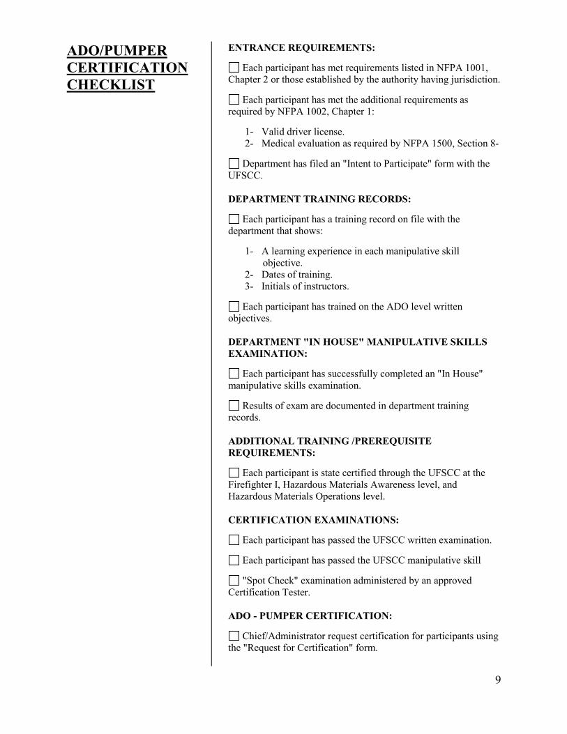
ADO/PUMPER CERTIFICATION CHECKLIST
ENTRANCE REQUIREMENTS:
Each participant has met requirements listed in NFPA 1001, Chapter 2 or those established by the authority having jurisdiction.
Each participant has met the additional requirements as required by NFPA 1002, Chapter 1:
1- Valid driver license. 2- Medical evaluation as required by NFPA 1500, Section 8-
Department has filed an "Intent to Participate" form with the
UFSCC. DEPARTMENT TRAINING RECORDS:
Each participant has a training record on file with the department that shows:
1- A learning experience in each manipulative skill objective. 2- Dates of training. 3- Initials of instructors.
Each participant has trained on the ADO level written
objectives. DEPARTMENT "IN HOUSE" MANIPULATIVE SKILLS EXAMINATION:
Each participant has successfully completed an "In House" manipulative skills examination.
Results of exam are documented in department training records. ADDITIONAL TRAINING /PREREQUISITE REQUIREMENTS:
Each participant is state certified through the UFSCC at the Firefighter I, Hazardous Materials Awareness level, and Hazardous Materials Operations level. CERTIFICATION EXAMINATIONS:
Each participant has passed the UFSCC written examination.
Each participant has passed the UFSCC manipulative skill
"Spot Check" examination administered by an approved Certification Tester. ADO - PUMPER CERTIFICATION:
Chief/Administrator request certification for participants using the "Request for Certification" form.
10
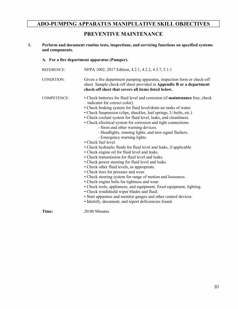
ADO-PUMPING APPARATUS MANIPULATIVE SKILL OBJECTIVES
PREVENTIVE MAINTENANCE
1. Perform and document routine tests, inspections, and servicing functions on specified systems and components.
A. For a fire department apparatus (Pumper).
REFERENCE: NFPA 1002, 2017 Edition, 4.2.1, 4.2.2, 4.3.7, 5.1.1
CONDITION: Given a fire department pumping apparatus, inspection form or check-off sheet. Sample check-off sheet provided in Appendix B or a department check-off sheet that covers all items listed below.
COMPETENCE: • Check batteries for fluid level and corrosion (if maintenance free, check
indicator for correct color). • Check braking system for fluid level/drain air tanks of water. • Check Suspension (clips, shackles, leaf springs, U-bolts, etc.) • Check coolant system for fluid level, leaks, and cleanliness. • Check electrical system for corrosion and tight connections. - Siren and other warning devices.
- Headlights, running lights, and turn signal flashers. - Emergency warning lights. • Check fuel level. • Check hydraulic fluids for fluid level and leaks, if applicable. • Check engine oil for fluid level and leaks. • Check transmission for fluid level and leaks. • Check power steering for fluid level and leaks. • Check other fluid levels, as appropriate. • Check tires for pressure and wear. • Check steering system for range of motion and looseness. • Check engine belts for tightness and wear. • Check tools, appliances, and equipment, fixed equipment, lighting. • Check windshield wiper blades and fluid. • Start apparatus and monitor gauges and other control devices. • Identify, document, and report deficiencies found. Time: 20:00 Minutes

11
B. Fire department pump system. REFERENCE: NFPA 1002, 2017 Edition, 5.1.1
CONDITION: Given a fire department pumping apparatus, maintenance and inspection form or check off sheet, determine readiness of fire pump on apparatus.
COMPETENCE: • Check water tank for level and leaks in system. • Check foam tank for level and leaks in system (if applicable). • Check primer oil, if applicable.
• Exercise all pump valves. • Check and clean intake strainers/anode. • Check pump gearbox/transfer case for proper oil level and traces of water. • Start apparatus and place apparatus in pump gear. • Operate the pump primer with all pump valves closed.
• Operate the transfer valve while pumping from booster tank or other water source (if applicable). • Check pump shaft for excessive leaks, if applicable.
• Operate the pump pressure control device(s). (Intake/discharge/pressure governor as applicable).
TIME: 20:00 Minutes
12
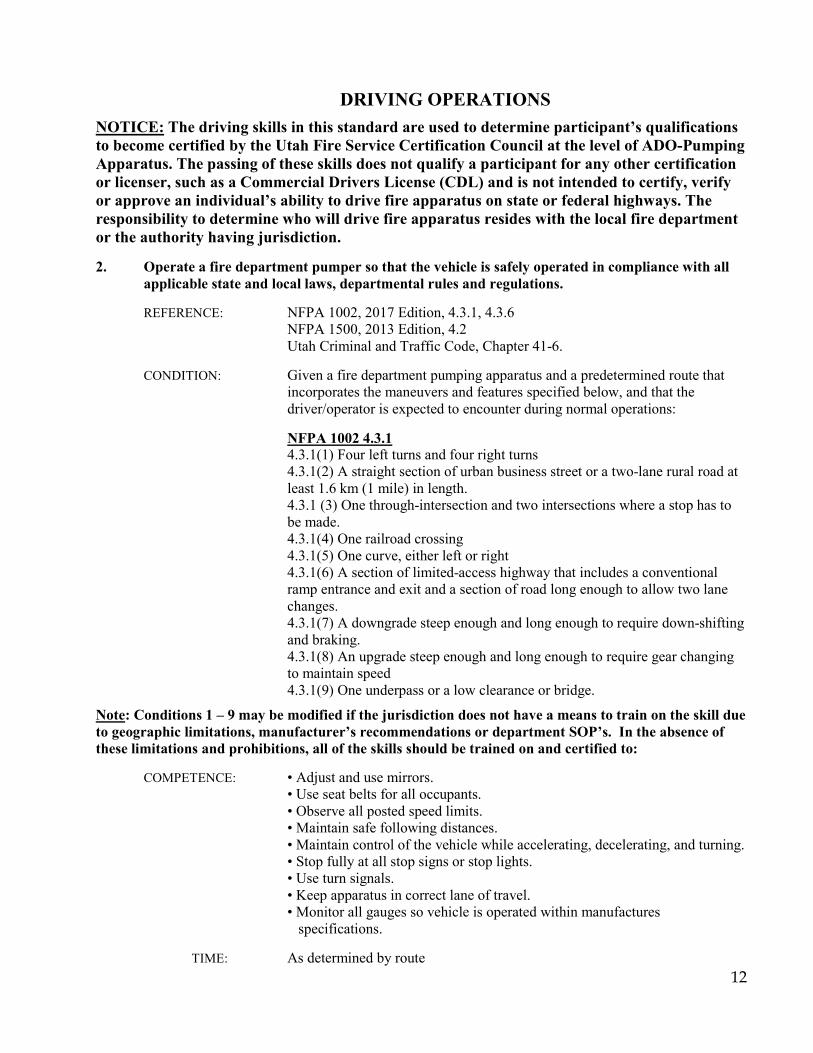
DRIVING OPERATIONS
NOTICE: The driving skills in this standard are used to determine participant’s qualifications to become certified by the Utah Fire Service Certification Council at the level of ADO-Pumping Apparatus. The passing of these skills does not qualify a participant for any other certification or licenser, such as a Commercial Drivers License (CDL) and is not intended to certify, verify or approve an individual’s ability to drive fire apparatus on state or federal highways. The responsibility to determine who will drive fire apparatus resides with the local fire department or the authority having jurisdiction. 2. Operate a fire department pumper so that the vehicle is safely operated in compliance with all
applicable state and local laws, departmental rules and regulations. REFERENCE: NFPA 1002, 2017 Edition, 4.3.1, 4.3.6 NFPA 1500, 2013 Edition, 4.2 Utah Criminal and Traffic Code, Chapter 41-6.
CONDITION: Given a fire department pumping apparatus and a predetermined route that incorporates the maneuvers and features specified below, and that the driver/operator is expected to encounter during normal operations:
NFPA 1002 4.3.1
4.3.1(1) Four left turns and four right turns 4.3.1(2) A straight section of urban business street or a two-lane rural road at least 1.6 km (1 mile) in length. 4.3.1 (3) One through-intersection and two intersections where a stop has to be made. 4.3.1(4) One railroad crossing 4.3.1(5) One curve, either left or right 4.3.1(6) A section of limited-access highway that includes a conventional ramp entrance and exit and a section of road long enough to allow two lane changes. 4.3.1(7) A downgrade steep enough and long enough to require down-shifting and braking. 4.3.1(8) An upgrade steep enough and long enough to require gear changing to maintain speed 4.3.1(9) One underpass or a low clearance or bridge.
Note: Conditions 1 – 9 may be modified if the jurisdiction does not have a means to train on the skill due to geographic limitations, manufacturer’s recommendations or department SOP’s. In the absence of these limitations and prohibitions, all of the skills should be trained on and certified to: COMPETENCE: • Adjust and use mirrors. • Use seat belts for all occupants. • Observe all posted speed limits. • Maintain safe following distances.
• Maintain control of the vehicle while accelerating, decelerating, and turning. • Stop fully at all stop signs or stop lights. • Use turn signals. • Keep apparatus in correct lane of travel. • Monitor all gauges so vehicle is operated within manufactures
specifications. TIME: As determined by route
13
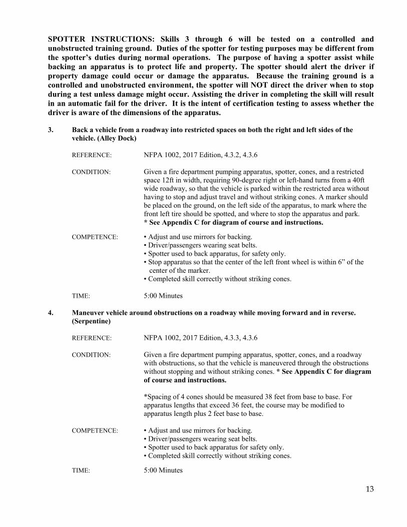
SPOTTER INSTRUCTIONS: Skills 3 through 6 will be tested on a controlled and unobstructed training ground. Duties of the spotter for testing purposes may be different from the spotter’s duties during normal operations. The purpose of having a spotter assist while backing an apparatus is to protect life and property. The spotter should alert the driver if property damage could occur or damage the apparatus. Because the training ground is a controlled and unobstructed environment, the spotter will NOT direct the driver when to stop during a test unless damage might occur. Assisting the driver in completing the skill will result in an automatic fail for the driver. It is the intent of certification testing to assess whether the driver is aware of the dimensions of the apparatus. 3. Back a vehicle from a roadway into restricted spaces on both the right and left sides of the
vehicle. (Alley Dock) REFERENCE: NFPA 1002, 2017 Edition, 4.3.2, 4.3.6
CONDITION: Given a fire department pumping apparatus, spotter, cones, and a restricted space 12ft in width, requiring 90-degree right or left-hand turns from a 40ft wide roadway, so that the vehicle is parked within the restricted area without having to stop and adjust travel and without striking cones. A marker should be placed on the ground, on the left side of the apparatus, to mark where the front left tire should be spotted, and where to stop the apparatus and park.
* See Appendix C for diagram of course and instructions. COMPETENCE: • Adjust and use mirrors for backing.
• Driver/passengers wearing seat belts. • Spotter used to back apparatus, for safety only.
• Stop apparatus so that the center of the left front wheel is within 6” of the center of the marker.
• Completed skill correctly without striking cones. TIME: 5:00 Minutes 4. Maneuver vehicle around obstructions on a roadway while moving forward and in reverse.
(Serpentine) REFERENCE: NFPA 1002, 2017 Edition, 4.3.3, 4.3.6
CONDITION: Given a fire department pumping apparatus, spotter, cones, and a roadway with obstructions, so that the vehicle is maneuvered through the obstructions without stopping and without striking cones. * See Appendix C for diagram of course and instructions.
*Spacing of 4 cones should be measured 38 feet from base to base. For
apparatus lengths that exceed 36 feet, the course may be modified to apparatus length plus 2 feet base to base.
COMPETENCE: • Adjust and use mirrors for backing.
• Driver/passengers wearing seat belts. • Spotter used to back apparatus for safety only. • Completed skill correctly without striking cones. TIME: 5:00 Minutes
14
5. Turn a vehicle around 180 degrees within a confined space. (Confined Space Turnaround) REFERENCE: NFPA 1002, 2017 Edition, 4.3.4, 4.3.6
CONDITION: Given a fire department pumping apparatus, spotter, cones, area where vehicle cannot make a U-turn without stopping and backing up, so that the vehicle is turned 180 degrees without crossing over or striking cones. * See Appendix C for diagram of course and instructions.
COMPETENCE: • Adjust and use mirrors for backing.
• Driver/passengers wearing seat belts. • Spotter used to back apparatus for safety only. • Completed skill correctly without crossing over or striking cones. TIME: 5:00 Minutes
6. Maneuver a vehicle in restricted horizontal clearances. (Diminishing Clearance) REFERENCE: NFPA 1002, 2017 Edition, 4.3.5, 4.3.6
CONDITION: Given a fire department pumping apparatus, spotter, cones, course that requires the operator to move through areas of restricted horizontal clearances, so that the operator accurately judges the ability of the vehicle to pass through the openings without striking cones. * See Appendix C for diagram of course and instructions.
COMPETENCE: • Adjust and use mirrors.
• Driver/passengers wearing seat belts. • Completed skill correctly without striking cones. • Place the apparatus bumper within 18” of the cone at the finish line without crossing over it. TIME: 5:00 Minutes
15
PUMPING OPERATIONS 7. Produce effective hand or master streams, given the source specified for the following, so that
the pump is safely engaged, all pressure control and vehicle safety devices are set, the rated flow for the nozzle is achieved and maintained and the apparatus is continuously monitored.
A. Fire Hydrant Transition/Handline. REFERENCE: NFPA 1002, 2017 Edition, 4.3.7, 5.2.1
CONDITION: Given a fire department pumping apparatus, supply hose (2 1/2” or larger), attack line minimum 100 feet 1 1/2” or 1 3/4” hoseline, appropriate fittings and tools, pre-established water supply not connected to the inlet, Operator plus 1-firefighter to assist with hydrant and 1-firefighter to assist with hoseline.
COMPETENCE: • Stop apparatus, set brake.
• Engage pump. • Chock wheels. • Engage tank to pump (department standard). • Open correct discharge valve and charge appropriate attack line. • Gradually develop pump discharge pressure in attack line. • Make supply line connection to intake. • Signal hydrant for water. • Smooth transition from tank water to hydrant supply (monitor valves, gauges, and throttle). • Set discharge relief valve or pressure governor as per department standard.
• Monitor discharge pressure. • Establish and verbalize correct PDP (within +/- 10 psi) and the method used
to determine PDP. TIME: 5:00 Minutes

16
B. Fire Hydrant – Master Stream Device. REFERENCE: NFPA 1002, 2017 Edition, 4.3.7, 5.2.1
CONDITION: Given a fire department pumping apparatus, supply hose (2 1/2” or larger), appropriate fittings and tools, Mounted master stream device or portable. pre- established water supply not connected to the inlet, Operator plus 1-firefighter to assist with hydrant and 2 firefighters to assist with hoselines and Master stream device (if portable master stream device is used).
COMPETENCE: • Stop apparatus, set brake.
• Engage pump. • Chock wheels. • Engage tank to pump (department standard). • Make supply line connection. • If using portable master stream device, set up device away from apparatus using a minimum of 100 feet of supply hose.
• Properly secure device. • Signal for water from hydrant. • Open appropriate discharge valve(s). • Gradually develop pump discharge pressure to master stream device. • Set discharge relief valves or pressure governor per department standard.
• Monitor discharge pressure. • Establish and verbalize correct PDP (within +/- 10 psi) and the method used
to determine PDP TIME: 5:00 Minutes for Mounted Master Stream Device 10:00 Minutes for Portable Master Stream Device C. Draft Supply Source – Handline. REFERENCE: NFPA 1002, 2017 Edition, 4.3.7, 5.2.1
CONDITION: Given a fire department pumping apparatus, hard suction intake hose, appropriate fittings and tools, 10 ft. ladder, portable water tank (if being used as water source), 100 ft. of 1 1/2” or 1 3/4” attack line. Operator plus 2- firefighters to assist with setting up equipment.
COMPETENCE: • Position apparatus at drafting location. • Connect sections of hard suction hose together (department standard). • Connect strainer to hard suction hose, attach rope (department standard). • Connect to apparatus, tighten all connections. • Place ladder into static water source (if necessary). • Lower intake hose into static source. • Engage pump. • Pick up draft. • Gradually open appropriate valve to charge hand-line. • Flow water from handline or master stream device for 1 minute at appropriate pressure. • Establish and verbalize correct PDP (within +/- 10 psi) and the method used to determine PDP TIME: 10:00 Minutes
17
8. Establish a relay pumping evolution, produce an effective water supply, so that the pump is safely engaged, all pressure control and vehicle safety devices are set, the rated flow is achieved, and the apparatus is continuously monitored for potential problems.
REFERENCE: NFPA 1002, 2017 Edition, 4.3.7, 5.2.5 CONDITION: Given 2 fire department pumping apparatus with 200 feet 2 1/2” or larger
hose, appropriate hose adapters and appliances, 4 firefighter team (2 firefighters per apparatus). With “Attack” pumper positioned 200 ft. from “Source” pumper. Candidate being evaluated will be at the Source Pumper.
* Relay Chart reference can be found in appendix E. COMPETENCE: • Position “Source” pumper at water source (hydrant or draft location). • Ensure supply lines from Source pumper are connected to Attack pumper. • Establish water supply to “Source” pumper intake. • All pumpers except source pumper open a discharge to exhaust air from
lines. • Pump required discharge pressure from Source pumper to Attack pumper, based on max distance/constant pressure relay method.
• Through radio communication ensure that the Attack pumper has water flowing from discharge opening at an appropriate pressure (20 psi intake as a minimum).
• Correctly shut down relay (from attack to source) TIME: 10:00 Minutes
18
9. Produce a foam fire stream so that properly proportioned foam is delivered. (USE THE COMPETENCY THAT IS APPROPRIATE FOR THE TYPE OF FOAM EQUIPMENT THAT YOUR DEPARTMENT HAS).
REFERENCE: NFPA 1002, 2017 Edition, 4.3.7, 5.2.6
CONDITION: Given a fire department pumping apparatus, foam concentrate, foam eductor, foam nozzle, or other portable foam producing equipment, with hoseline set up, 2 firefighter team to manage the hose line.
COMPETENCE: • Set concentrate percentage on the proportioner. • Place pickup tube in foam container. • Ensure nozzle flow rate and eductor flow rate match. • Set appropriate pump discharge pressure.
• Ensure back pressure does not exceed 65% to 70% of rated eductor inlet pressure.
• Deliver properly proportioned foam. • Clean/flush system when skill complete (not included in time limit). • Establish and verbalize correct PDP (within +/- 10 psi) and the method used to determine PDP.
OR CONDITION: Given a fire department pumping apparatus, foam concentrate, apparatus
mounted foam system, foam nozzle, with hoseline set up, 2 firefighter team to manage the hose line.
COMPETENCE: • Set concentrate percentage on the proportioner. • Set metering valve. • Set appropriate pump discharge pressure. • Deliver properly proportioned foam. • Clean/flush system when skill complete (not included in time limit). • Establish and verbalize correct PDP (within +/- 10 psi) and the method used to determine PDP.
TIME: 5:00 Minutes
19
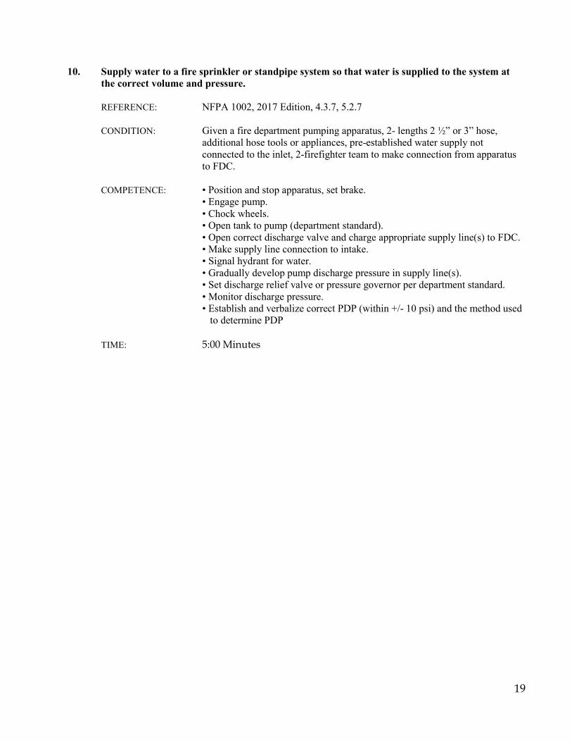
10. Supply water to a fire sprinkler or standpipe system so that water is supplied to the system at
the correct volume and pressure. REFERENCE: NFPA 1002, 2017 Edition, 4.3.7, 5.2.7
CONDITION: Given a fire department pumping apparatus, 2- lengths 2 ½” or 3” hose, additional hose tools or appliances, pre-established water supply not connected to the inlet, 2-firefighter team to make connection from apparatus to FDC.
COMPETENCE: • Position and stop apparatus, set brake.
• Engage pump. • Chock wheels. • Open tank to pump (department standard). • Open correct discharge valve and charge appropriate supply line(s) to FDC. • Make supply line connection to intake. • Signal hydrant for water. • Gradually develop pump discharge pressure in supply line(s). • Set discharge relief valve or pressure governor per department standard.
• Monitor discharge pressure. • Establish and verbalize correct PDP (within +/- 10 psi) and the method used to determine PDP TIME: 5:00 Minutes
20
APPENDIX - A TRAINING RECORD

21
UTAH FIRE SERVICE CERTIFICATION SYSTEM APPARATUS DRIVER OPERATOR - PUMPER NFPA 1002, 2017 Edition
ADO - PUMPER TRAINING RECORD – IN-HOUSE COMPREHENSIVE EXAM
NAME: DEPARTMENT:
Training Records must have the date and instructor’s original signature and/or initials for each line.
SECTION TRAINING RECORD IN-HOUSE COMP. EXAM
MANIPULATIVE SKILL DEMONSTRATE
DATE INST DATE INST PASS PREVENTIVE MAINTENACE
1A. Perform and document routine tests, inspections, and servicing functions for a fire department apparatus.
1B. Perform and document routine tests, inspections, and servicing functions for the pumping system on apparatus.
DRIVING OPERATIONS
2. Operate a fire department pumper so that the vehicle is safely operated in compliance with all state and local laws, department rules and regulations.
3. Back a vehicle from a roadway into restricted spaces on both right and left sides of the vehicle. (Alley Dock)
4. Maneuver vehicle around obstructions on a roadway while moving forward and in reverse. (Serpentine)
5. Turn a vehicle around 180 degrees within a confined space. (Confined Space Turnaround)
6. Maneuver a vehicle in restricted horizontal clearances. (Diminishing Clearance)
PUMPING OPERATIONS
7A. Produce effective fire stream, hydrant – transition/handline.
7B. Produce effective fire stream, hydrant – master stream.
7C. Draft supply source – handline.
8. Establish a relay pumping operation.
9. Produce a foam fire stream so that properly proportioned foam is delivered.
10. Supply a sprinkler/standpipe system.
22
APPENDIX - B WEEKLY VEHICLE REPORT
23
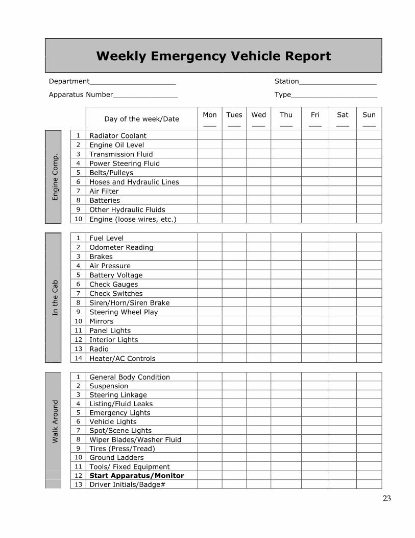
Weekly Emergency Vehicle Report
Department____________________
Station__________________
Apparatus Number_______________
Type____________________
Day of the week/Date Mon
___ Tues ___
Wed ___
Thu ___
Fri ___
Sat ___
Sun ___
Engi
ne C
omp.
1 Radiator Coolant
2 Engine Oil Level
3 Transmission Fluid
4 Power Steering Fluid
5 Belts/Pulleys
6 Hoses and Hydraulic Lines
7 Air Filter
8 Batteries
9 Other Hydraulic Fluids
10 Engine (loose wires, etc.)
In t
he C
ab
1 Fuel Level
2 Odometer Reading
3 Brakes
4 Air Pressure
5 Battery Voltage
6 Check Gauges
7 Check Switches
8 Siren/Horn/Siren Brake
9 Steering Wheel Play
10 Mirrors
11 Panel Lights
12 Interior Lights
13 Radio
14 Heater/AC Controls
Wal
k Aro
und
1 General Body Condition
2 Suspension
3 Steering Linkage
4 Listing/Fluid Leaks
5 Emergency Lights
6 Vehicle Lights
7 Spot/Scene Lights
8 Wiper Blades/Washer Fluid
9 Tires (Press/Tread)
10 Ground Ladders
11 Tools/ Fixed Equipment
12 Start Apparatus/Monitor
13 Driver Initials/Badge#

24
Day of the week Mon Tues Wed Thu Fri Sat Sun
Aer
ial I
nspe
ctio
n
1 Hydraulic Fluid Level
2 Hydraulic System/PTO
3 Stabilizers and Pads
4 Interlocks
5 Leveling Gauges
6 Aerial Control Stations
7 Operate Aerial
8 Visual Inspection
9 Slides/Slide Blocks/Rollers
10 Nozzle/Waterway
11 Communication System
12 Master Stream Controls
13 Spot Lights/Flood Lights
14 Lubrication
15 Cables
16 Pulleys
17 Rams/Cylinders
18 Hydraulic Hoses/Tubing
19 Breathing Air
20 Attached Tools/Equipment
21 E.P.U. Operation (weekly)
Pum
p Che
ck
1 Tank Water Level
2 Foam Level
3 Primer Oil Level
4 Pump Transfer Case Oil Level
5 Intake Strainers/Anode
6 Relief Valve Strainer
7 Operate all Valves/Drains
8 Primer Operation
9 Operate Transfer Valve
10 Pump Operation
11 Relief valve/Governor Op.
12 LDH Bleeder
Remarks By Person Completing Form Date Name
25
APPENDIX - C DRIVING SKILLS DIAGRAMS / INSTRUCTIONS
26
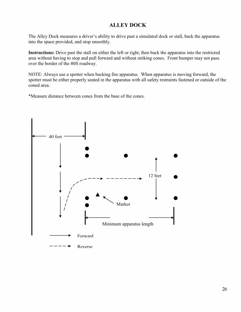
ALLEY DOCK The Alley Dock measures a driver’s ability to drive past a simulated dock or stall, back the apparatus into the space provided, and stop smoothly. Instructions: Drive past the stall on either the left or right, then back the apparatus into the restricted area without having to stop and pull forward and without striking cones. Front bumper may not pass over the border of the 40ft roadway. NOTE: Always use a spotter when backing fire apparatus. When apparatus is moving forward, the spotter must be either properly seated in the apparatus with all safety restraints fastened or outside of the coned area. *Measure distance between cones from the base of the cones.
Marker
40 feet
12 feet
Forward
Reverse
Minimum apparatus length
27
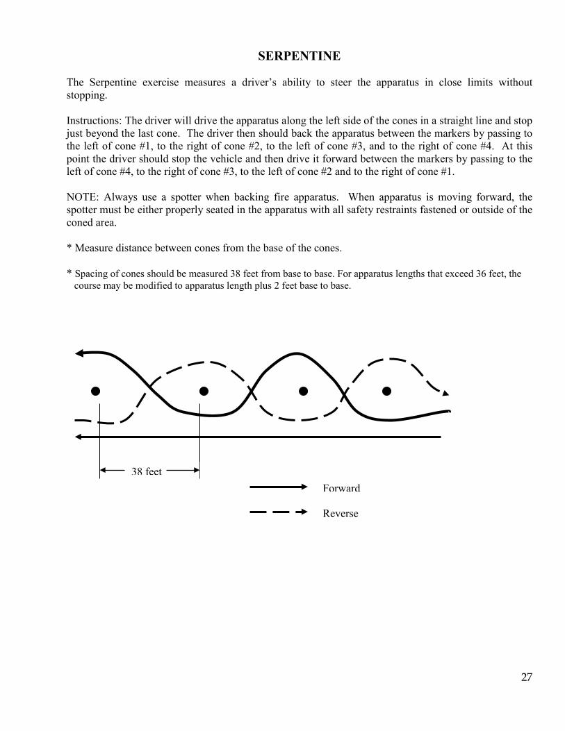
SERPENTINE The Serpentine exercise measures a driver’s ability to steer the apparatus in close limits without stopping. Instructions: The driver will drive the apparatus along the left side of the cones in a straight line and stop just beyond the last cone. The driver then should back the apparatus between the markers by passing to the left of cone #1, to the right of cone #2, to the left of cone #3, and to the right of cone #4. At this point the driver should stop the vehicle and then drive it forward between the markers by passing to the left of cone #4, to the right of cone #3, to the left of cone #2 and to the right of cone #1. NOTE: Always use a spotter when backing fire apparatus. When apparatus is moving forward, the spotter must be either properly seated in the apparatus with all safety restraints fastened or outside of the coned area. * Measure distance between cones from the base of the cones. * Spacing of cones should be measured 38 feet from base to base. For apparatus lengths that exceed 36 feet, the course may be modified to apparatus length plus 2 feet base to base.
38 feet
Reverse
Forward
28
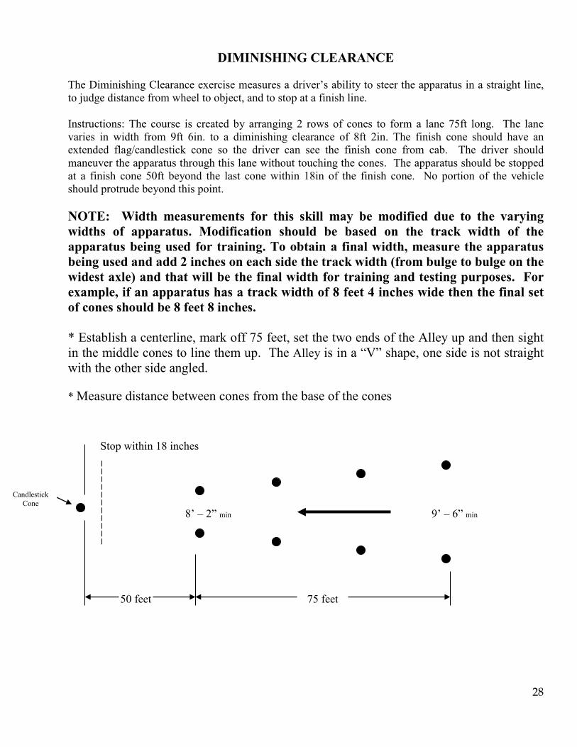
DIMINISHING CLEARANCE The Diminishing Clearance exercise measures a driver’s ability to steer the apparatus in a straight line, to judge distance from wheel to object, and to stop at a finish line. Instructions: The course is created by arranging 2 rows of cones to form a lane 75ft long. The lane varies in width from 9ft 6in. to a diminishing clearance of 8ft 2in. The finish cone should have an extended flag/candlestick cone so the driver can see the finish cone from cab. The driver should maneuver the apparatus through this lane without touching the cones. The apparatus should be stopped at a finish cone 50ft beyond the last cone within 18in of the finish cone. No portion of the vehicle should protrude beyond this point. NOTE: Width measurements for this skill may be modified due to the varying widths of apparatus. Modification should be based on the track width of the apparatus being used for training. To obtain a final width, measure the apparatus being used and add 2 inches on each side the track width (from bulge to bulge on the widest axle) and that will be the final width for training and testing purposes. For example, if an apparatus has a track width of 8 feet 4 inches wide then the final set of cones should be 8 feet 8 inches. * Establish a centerline, mark off 75 feet, set the two ends of the Alley up and then sight in the middle cones to line them up. The Alley is in a “V” shape, one side is not straight with the other side angled. * Measure distance between cones from the base of the cones
Stop within 18 inches
50 feet
8’ – 2” min
9’ – 6” min
75 feet
Candlestick Cone
29
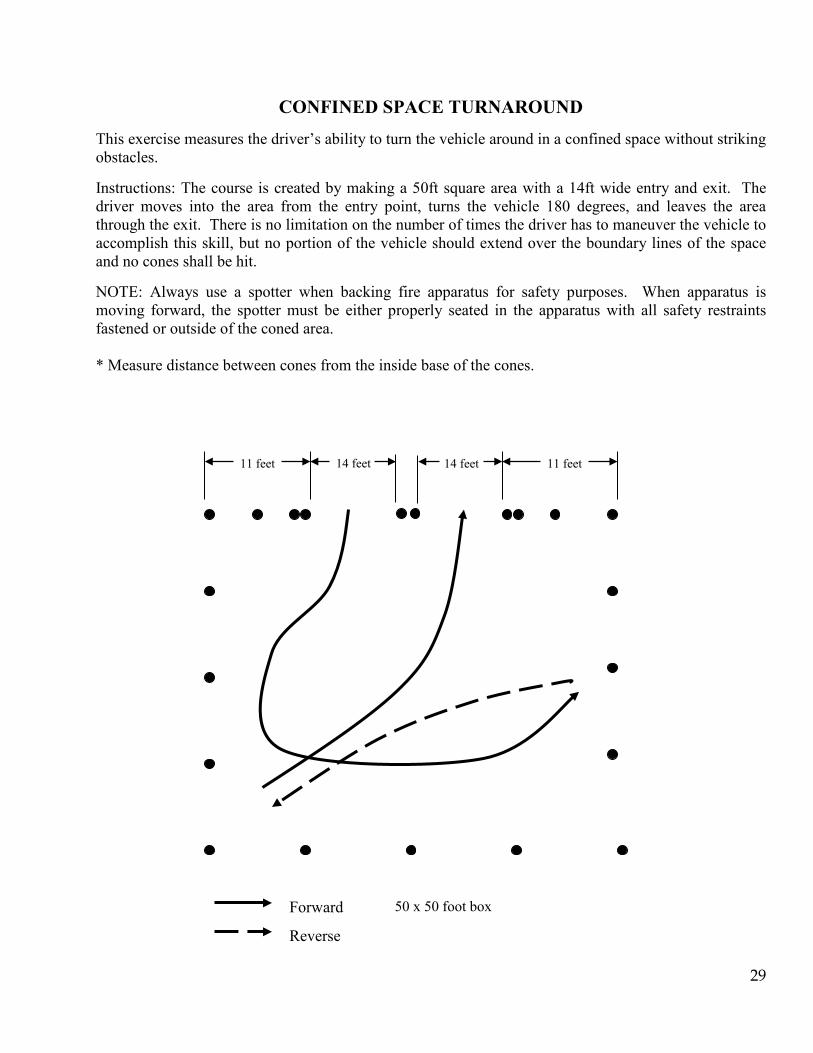
CONFINED SPACE TURNAROUND
This exercise measures the driver’s ability to turn the vehicle around in a confined space without striking obstacles. Instructions: The course is created by making a 50ft square area with a 14ft wide entry and exit. The driver moves into the area from the entry point, turns the vehicle 180 degrees, and leaves the area through the exit. There is no limitation on the number of times the driver has to maneuver the vehicle to accomplish this skill, but no portion of the vehicle should extend over the boundary lines of the space and no cones shall be hit. NOTE: Always use a spotter when backing fire apparatus for safety purposes. When apparatus is moving forward, the spotter must be either properly seated in the apparatus with all safety restraints fastened or outside of the coned area. * Measure distance between cones from the inside base of the cones.
14 feet 14 feet 11 feet 11 feet
Forward
Reverse
50 x 50 foot box
30
FIRE FLOW FORMULAS
APPENDIX - D
31
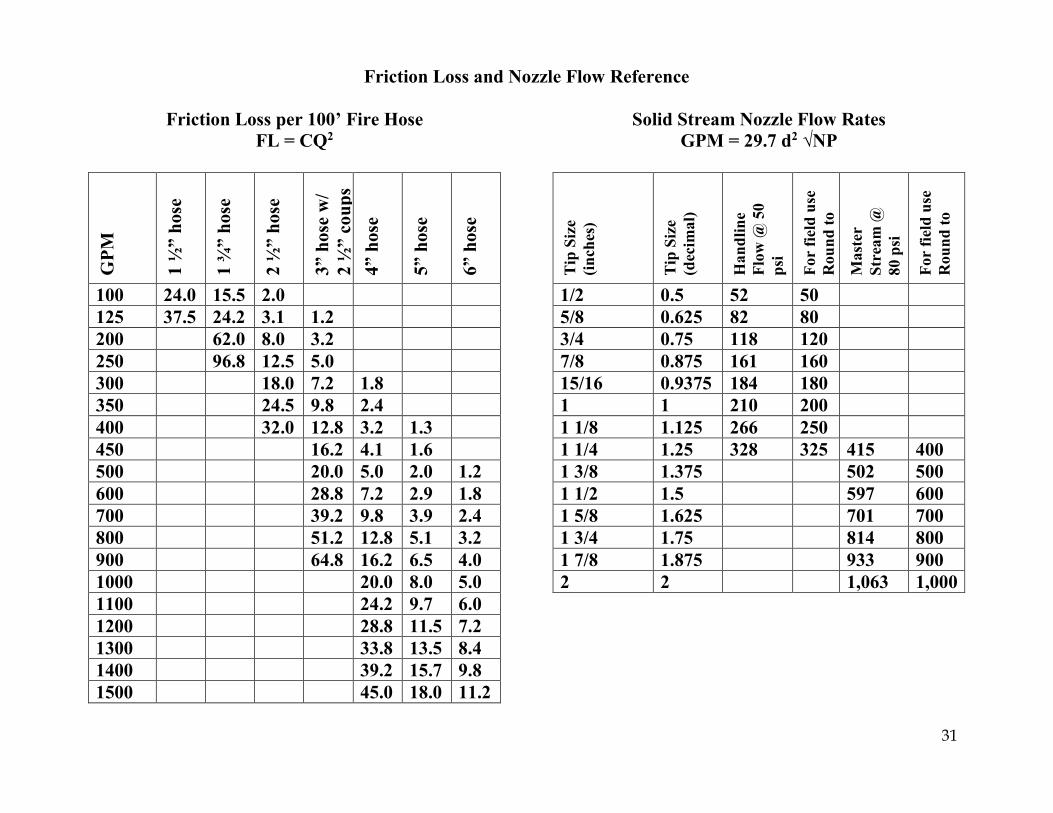
Friction Loss and Nozzle Flow Reference
Friction Loss per 100’ Fire Hose FL = CQ2
GPM
1 ½
” ho
se
1 ¾
” ho
se
2 ½
” ho
se
3” h
ose
w/
2 ½
” co
ups
4” h
ose
5” h
ose
6” h
ose
100 24.0 15.5 2.0 125 37.5 24.2 3.1 1.2 200 62.0 8.0 3.2 250 96.8 12.5 5.0 300 18.0 7.2 1.8 350 24.5 9.8 2.4 400 32.0 12.8 3.2 1.3 450 16.2 4.1 1.6 500 20.0 5.0 2.0 1.2 600 28.8 7.2 2.9 1.8 700 39.2 9.8 3.9 2.4 800 51.2 12.8 5.1 3.2 900 64.8 16.2 6.5 4.0 1000 20.0 8.0 5.0 1100 24.2 9.7 6.0 1200 28.8 11.5 7.2 1300 33.8 13.5 8.4 1400 39.2 15.7 9.8 1500 45.0 18.0 11.2
Solid Stream Nozzle Flow Rates GPM = 29.7 d2 √NP
Tip
Siz
e (in
ches
)
Tip
Siz
e (d
ecim
al)
Han
dlin
e Fl
ow @
50
psi
For
field
use
R
ound
to
Mas
ter
Stre
am @
80
psi
For
field
use
R
ound
to
1/2 0.5 52 50 5/8 0.625 82 80 3/4 0.75 118 120 7/8 0.875 161 160 15/16 0.9375 184 180 1 1 210 200 1 1/8 1.125 266 250 1 1/4 1.25 328 325 415 400 1 3/8 1.375 502 500 1 1/2 1.5 597 600 1 5/8 1.625 701 700 1 3/4 1.75 814 800 1 7/8 1.875 933 900 2 2 1,063 1,000

32
Fire Hose Friction Loss Coefficients – Single Line Hose diameter and type coefficient (C) ¾” booster 1,100 1” booster 150 1 ¼” booster 80 1 ½” 24 1 ¾” with 1 ½” couplings 15.5 2” 8 2 ½” 2 3” with 2 ½” couplings 0.8 3” with 3” couplings 0.677 3 ½” 0.34 4” hose 0.2 4 ½” hose 0.1 5” hose 0.08 6” hose 0.05 Standpipe Friction Loss Coefficients 4” pipe 0.374 5” pipe 0.126 6” pipe 0.052 Nozzle Pressures Solid stream nozzles – handline 50 psi Solid stream nozzles – master streams 80 psi Fog nozzles – most types 100 psi *Fog nozzle pressures may vary by manufacturer. Friction Loss Allowances – Appliances, Apparatus, Systems Master stream appliances flowing at capacity 25 psi Aerial devices 25 psi Wye and manifold appliances flowing >350 GPM 10 psi Standpipe system 25 psi
Fire Hose Friction Loss Coefficients – Siamese Lines of Equal Length Hose diameter and type coefficient (C) Two 2 ½” 0.5 Three 2 ½” 0.22 Two 3” with 2 ½” couplings 0.2 One 3” with 2 ½” couplings, one 2 ½” 0.3 One 3” with 3” couplings, One 2 ½” 0.27 Two 2 ½”, one 3” with 2 ½” couplings 0.16 Two 3” with 2 ½” couplings, one 2 ½” 0.12 Additional Water Available from Hydrant Percent drop = (static pressure – residual pressure) X 100 Static pressure Percent decrease of Additional Water pump intake pressure available 0-10% 3 times amount being delivered 11-15% 2 times amount being delivered 16-25% same amount as being delivered 25% + less than the amount being delivered First Digit Method
Get the static pressure, open the line, get the residual pressure Subtract the residual pressure from the static pressure = psi drop Multiply the first digit of the static by 1,2, or 3 = volumes available If the psi drop is = or < 1st digit x 1 = 3 like volumes are available If the psi drop is = or < 1st digit x 2 = 2 like volumes are available If the psi drop is = or < 1st digit x 3 = 1 like volume is available Any psi drop greater than 1st digit x3 = no additional water available
33
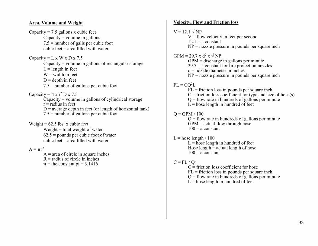
Area, Volume and Weight Capacity = 7.5 gallons x cubic feet Capacity = volume in gallons 7.5 = number of galls per cubic foot cubic feet = area filled with water Capacity = L x W x D x 7.5 Capacity = volume in gallons of rectangular storage L = length in feet W = width in feet D = depth in feet 7.5 = number of gallons per cubic foot Capacity = π x r2 D x 7.5 Capacity = volume in gallons of cylindrical storage r = radius in feet D = average depth in feet (or length of horizontal tank) 7.5 = number of gallons per cubic foot
Weight = 62.5 lbs. x cubic feet Weight = total weight of water 62.5 = pounds per cubic foot of water cubic feet = area filled with water A = πr2 A = area of circle in square inches R = radius of circle in inches π = the constant pi = 3.1416
Velocity, Flow and Friction loss V = 12.1 √ NP V = flow velocity in feet per second 12.1 = a constant NP = nozzle pressure in pounds per square inch GPM = 29.7 x d2 x √ NP GPM = discharge in gallons per minute 29.7 = a constant for fire protection nozzles d = nozzle diameter in inches NP = nozzle pressure in pounds per square inch FL = CQ2L FL = friction loss in pounds per square inch C = friction loss coefficient for type and size of hose(s) Q = flow rate in hundreds of gallons per minute L = hose length in hundred of feet Q = GPM / 100 Q = flow rate in hundreds of gallons per minute GPM = actual flow through hose 100 = a constant L = hose length / 100 L = hose length in hundred of feet Hose length = actual length of hose 100 = a constant C = FL / Q2 C = friction loss coefficient for hose FL = friction loss in pounds per square inch Q = flow rate in hundreds of gallons per minute L = hose length in hundred of feet

34
Elevation Pressure = 0.5 H Elev. Press. = Elevation pressure in psi
0.5 = a constant H = height in feet
Elevation Pressure = 5 psi x (number of stories -1) PDP = NP + TPL PDP = Pump discharge pressure in psi NP = Nozzle pressure in psi
TPL = Total pressure loss in psi (appliance, friction and elevation losses)
NR = 1.57 d2NP NR = solid stream nozzle reaction in pounds 1.57 = a constant for solid stream nozzles d = nozzle diameter in inches
NP = nozzle pressure in pounds per square inch
NR = 0.0505 GPM √ NP NR = fog nozzle reaction in pounds 0.0505 = a constant for fog nozzles GPM = actual flow in gallons per minute NP = nozzle pressure in pounds per square inch L = 1.13 Hg L = height of lift in feet 1.13 = a constant HG = inches of mercury
Pressure correction = lift + total intake friction loss 2.3 NPDP PPS = PDP – intake pressure NPDP PPS = net pump discharge pressure at positive
pressure source Intake Pressure = intake pressure from positive pressure
source NPDP Draft = PDP + pressure correction NPDP Draft = net pump discharge pressure at draft Pressure correction = pressure correction for draft FL per 100 feet = Q2 FL = friction loss in 100 feet of 3” hose Q = flow in hundreds of galls per minute FL per 100 feet = Q2 / 5 FL = friction loss in 100 feet of 4” hose Q = flow in hundreds of gallons per minute FL per 100 feet = Q2 / 10 FL = friction loss in 100 feet of 5’ hose Q = flow in hundreds of gallons per minute
35
APPENDIX - E RELAY CHART

36
Maximum Distance Relay Implementing a Maximum Distance Relay operation
Step 1, Determine relay distance Step 2, Determine required flow Step 3, Determine maximum distance between pumpers Step 4, Divide relay distance by maximum distance from table 1, round result up and add one additional pumper Step 5, Position Attack Pumper Step 6, Position Source at "Key" hydrant Step 7, Lay out hose and place Relay Pumpers at intervals determined by Table 1 Step 8, All pumpers except source pumper open a discharge to exhaust air from the lines Step 9, Source pumper throttles up to proper PDP Step 10, 1st Relay pumper closes unused discharge once a steady stream of water flows through it, then throttles up to proper PDP - All successive Relay pumpers follow the same procedure Step 11, All Driver/Operators set their intake relief valves, as needed. Step 12, Attack pumper adjusts PDP to supply attack lines. - Maintain water flow during temporary shutdowns by using one or more discharges as waste or dump lines Example: (1,000 gpm relay over 10,000 feet using 5" LDH) 10000÷2050=4.87(5)+1=6 Pumpers total
Table 1 - Maximum distance relay lengths in feet Flow in
gpm One 2 1/2 One 3 One 4 One 5 Two 2 1/2's
One 2 1/2 & one 3 Two 3's
250 1,440 3,600 13,200 33,000 5,760 9,600 14,400 500 360 900 3,300 8,250 1,440 2,400 3,600 750 160 400 1,450 3670 640 1050 1,600 1000 90 225 825 2,050 360 600 900 1250* 50 140 525 1,320 200 375 500
Maximum distance relay pump discharge pressure 2 1/2 & 3 inch - Maintain 200 psi PDP 4 & 5 inch - Maintain 185 psi PDP *1,250 gpm requires a 1,750 gpm pump to achieve. * PDP accounts for 20 psi residual pressure for the next pumper in the relay
Key positions in a relay operation Source Pumper - Positioned at the "Key" hydrant Relay Pumper/Pumpers - Spaced evenly throughout the relay at intervals determined from Table 1 Attack Pumper - Placed at a forward "Key" attack position 1 mile = 5280 Feet
37
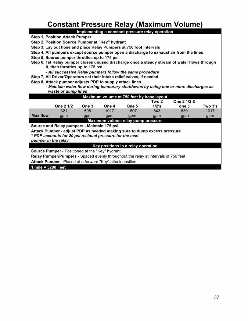
Constant Pressure Relay (Maximum Volume) Implementing a constant pressure relay operation
Step 1, Position Attack Pumper Step 2, Position Source Pumper at "Key" hydrant Step 3, Lay out hose and place Relay Pumpers at 750 foot intervals Step 4, All pumpers except source pumper open a discharge to exhaust air from the lines Step 5, Source pumper throttles up to 175 psi Step 6, 1st Relay pumper closes unused discharge once a steady stream of water flows through it, then throttles up to 175 psi. - All successive Relay pumpers follow the same procedure Step 7, All Driver/Operators set their intake relief valves, if needed. Step 8, Attack pumper adjusts PDP to supply attack lines. - Maintain water flow during temporary shutdowns by using one or more discharges as waste or dump lines
Maximum volume at 750 feet by hose layout
One 2 1/2 One 3 One 4 One 5 Two 2 1/2's
One 2 1/2 & one 3 Two 3's
Max flow 321 gpm
508 gpm
1017 gpm
1607 gpm
643 gpm
830 gpm
1017 gpm
Maximum volume relay pump pressure Source and Relay pumpers - Maintain 175 psi Attack Pumper - adjust PDP as needed making sure to dump excess pressure * PDP accounts for 20 psi residual pressure for the next pumper in the relay
Key positions in a relay operation Source Pumper - Positioned at the "Key" hydrant Relay Pumper/Pumpers - Spaced evenly throughout the relay at intervals of 750 feet Attack Pumper - Placed at a forward "Key" attack position 1 mile = 5280 Feet
38
APPENDIX - F IN-TAKE HOSE DRAFTING CHART

39
ALLOWANCES FOR FRICTION LOSS INTAKE HOSE
RATED CAPACITY OF THE PUMP IN
GPM
DIAMETER OF THE INTAKE
HOSE IN INCHES
FOR EVERY 10’ OF INTAKE HOSE
ALLOWANCE IN FEET FOR EACH ADDITIONAL 10’
OF INTAKE HOSE
500 4 4 ½
6 3 ½
Plus 1 Plus ½
750 4 5
7 4 ½
Plus 1 ½ Plus 1
1000 4 ½ 5 6
12 4 ½ 4
Plus 2 ½ Plus 1 ½ Plus ½
1250 5 6
12 ½ 6 ½
Plus 2 Plus ½
1500 5 (dual) 6 (dual)
4 ½ 2
Plus 1 Plus ½
1750 5(dual) 6(dual)
6 ½ 3
Plus 1 Plus ½
2000 5(dual) 6(dual)
8 4
Plus 1 ½ Plus ½
FROM TABLE 11.2A IFSTA ADO-P CH. 11
DRAFTING GUIDELINES
It is important to know the difference in elevation between the pump and the water source when drafting water from a pond or stream. When drafting water, the air at atmospheric pressure is removed from the hose line, creating a vacuum (negative pressure) within the pump chamber. The atmospheric pressure (weight of air) on the water's surface forces the water up through the suction hose to the pump.
The maximum height to which an engine or pump can lift water is determined by the atmospheric pressure. At sea level, the atmosphere exerts an average pressure of 14.7 pounds per square inch (psi). Atmospheric pressure will vary due to changes in the weather. However, these changes tend to moderate themselves so that the average pressure will tend to go back toward 14.7 pounds per square inch. That is why it is safe to use this value of 14.7 pounds per square inch as a constant for calculations.
Maximum Lift: 14.7 x 2.304
Attainable Lift: Current Elevation x 2.304
Retrieved from, http://math.fire.org/index.php?option=com_content&view=article&id=32&Itemid=46
40
APPENDIX - G 7 -STEP BRAKE SYSTEM CHECK GUIDE
41
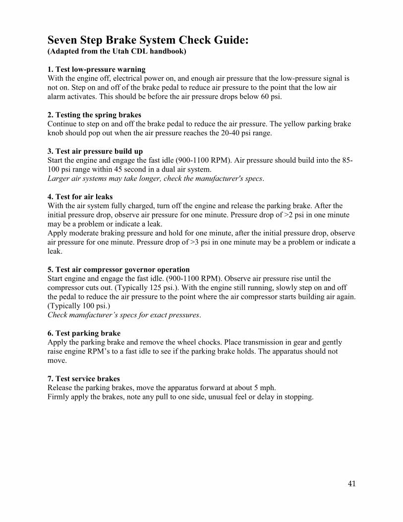
Seven Step Brake System Check Guide: (Adapted from the Utah CDL handbook) 1. Test low-pressure warning With the engine off, electrical power on, and enough air pressure that the low-pressure signal is not on. Step on and off of the brake pedal to reduce air pressure to the point that the low air alarm activates. This should be before the air pressure drops below 60 psi. 2. Testing the spring brakes Continue to step on and off the brake pedal to reduce the air pressure. The yellow parking brake knob should pop out when the air pressure reaches the 20-40 psi range. 3. Test air pressure build up Start the engine and engage the fast idle (900-1100 RPM). Air pressure should build into the 85-100 psi range within 45 second in a dual air system. Larger air systems may take longer, check the manufacturer's specs. 4. Test for air leaks With the air system fully charged, turn off the engine and release the parking brake. After the initial pressure drop, observe air pressure for one minute. Pressure drop of >2 psi in one minute may be a problem or indicate a leak. Apply moderate braking pressure and hold for one minute, after the initial pressure drop, observe air pressure for one minute. Pressure drop of >3 psi in one minute may be a problem or indicate a leak. 5. Test air compressor governor operation Start engine and engage the fast idle. (900-1100 RPM). Observe air pressure rise until the compressor cuts out. (Typically 125 psi.). With the engine still running, slowly step on and off the pedal to reduce the air pressure to the point where the air compressor starts building air again. (Typically 100 psi.) Check manufacturer’s specs for exact pressures. 6. Test parking brake Apply the parking brake and remove the wheel chocks. Place transmission in gear and gently raise engine RPM’s to a fast idle to see if the parking brake holds. The apparatus should not move. 7. Test service brakes Release the parking brakes, move the apparatus forward at about 5 mph. Firmly apply the brakes, note any pull to one side, unusual feel or delay in stopping.

42
APPENDIX - H PROCTOR INSTRUCTIONS
43
Proctor Instructions for “IN-HOUSE” Comprehensive Examination
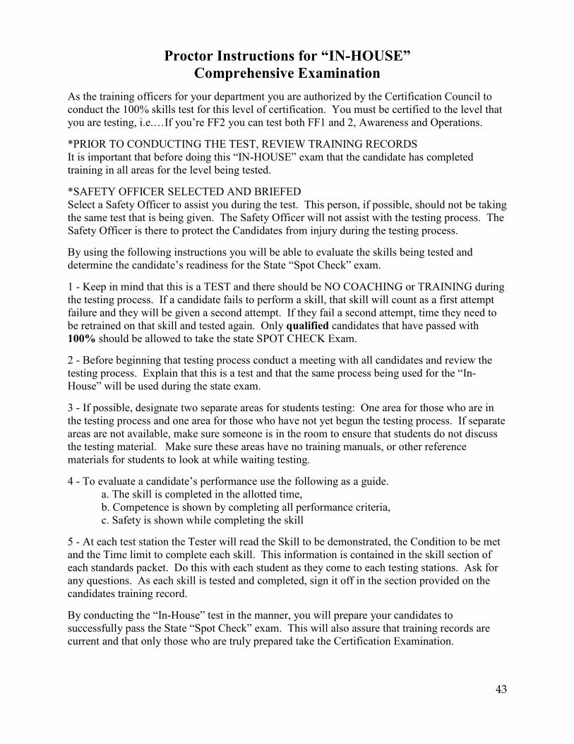
As the training officers for your department you are authorized by the Certification Council to conduct the 100% skills test for this level of certification. You must be certified to the level that you are testing, i.e.…If you’re FF2 you can test both FF1 and 2, Awareness and Operations. *PRIOR TO CONDUCTING THE TEST, REVIEW TRAINING RECORDS It is important that before doing this “IN-HOUSE” exam that the candidate has completed training in all areas for the level being tested. *SAFETY OFFICER SELECTED AND BRIEFED Select a Safety Officer to assist you during the test. This person, if possible, should not be taking the same test that is being given. The Safety Officer will not assist with the testing process. The Safety Officer is there to protect the Candidates from injury during the testing process. By using the following instructions you will be able to evaluate the skills being tested and determine the candidate’s readiness for the State “Spot Check” exam. 1 - Keep in mind that this is a TEST and there should be NO COACHING or TRAINING during the testing process. If a candidate fails to perform a skill, that skill will count as a first attempt failure and they will be given a second attempt. If they fail a second attempt, time they need to be retrained on that skill and tested again. Only qualified candidates that have passed with 100% should be allowed to take the state SPOT CHECK Exam. 2 - Before beginning that testing process conduct a meeting with all candidates and review the testing process. Explain that this is a test and that the same process being used for the “In-House” will be used during the state exam. 3 - If possible, designate two separate areas for students testing: One area for those who are in the testing process and one area for those who have not yet begun the testing process. If separate areas are not available, make sure someone is in the room to ensure that students do not discuss the testing material. Make sure these areas have no training manuals, or other reference materials for students to look at while waiting testing. 4 - To evaluate a candidate’s performance use the following as a guide. a. The skill is completed in the allotted time, b. Competence is shown by completing all performance criteria, c. Safety is shown while completing the skill 5 - At each test station the Tester will read the Skill to be demonstrated, the Condition to be met and the Time limit to complete each skill. This information is contained in the skill section of each standards packet. Do this with each student as they come to each testing stations. Ask for any questions. As each skill is tested and completed, sign it off in the section provided on the candidates training record. By conducting the “In-House” test in the manner, you will prepare your candidates to successfully pass the State “Spot Check” exam. This will also assure that training records are current and that only those who are truly prepared take the Certification Examination.
44
APPENDIX - I CERTIFICATION FORMS
45
Utah Fire Service Certification Council
INTENT TO PARTICIPATE
Organization Information
The following organization intends to participate in the Utah Fire Service Certification Program:
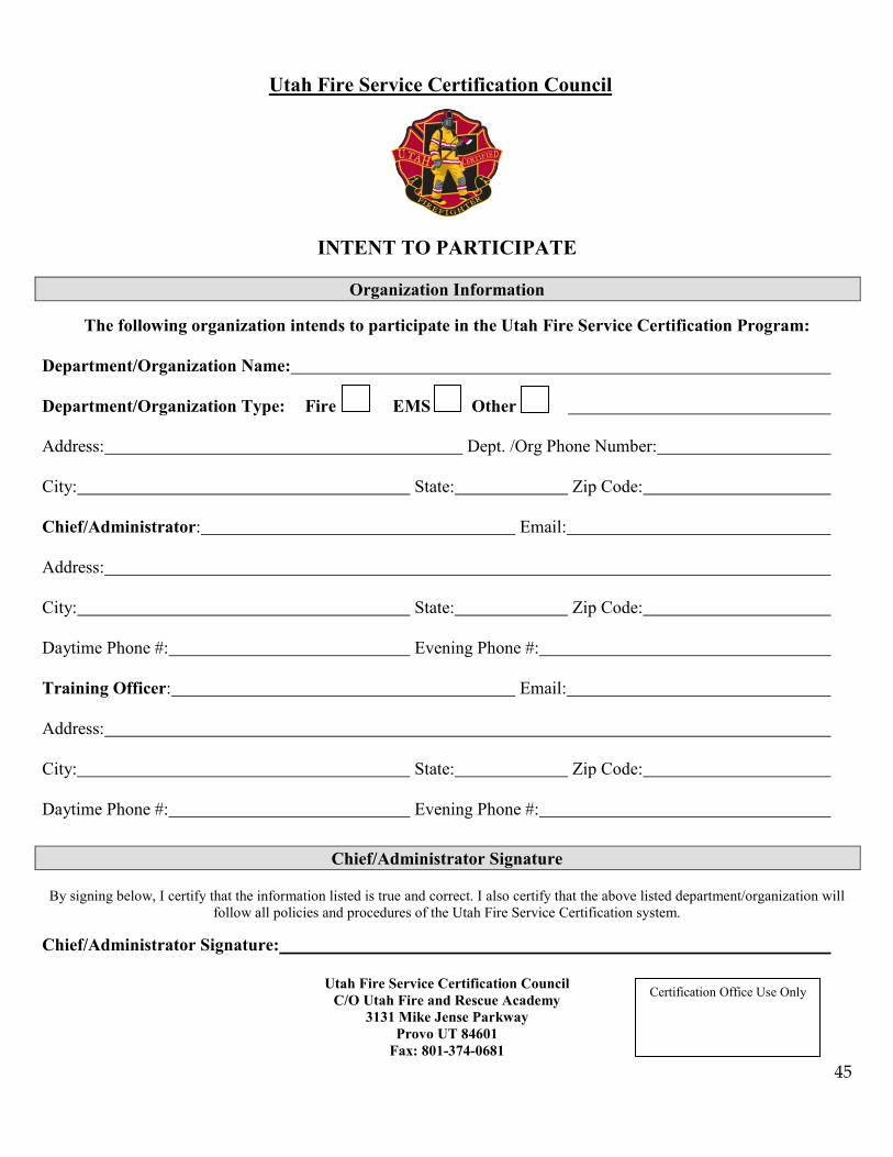
Department/Organization Name: Department/Organization Type: Fire EMS Other Address: Dept. /Org Phone Number: City: State: Zip Code:
Chief/Administrator: Email: Address: City: State: Zip Code: Daytime Phone #: Evening Phone #: Training Officer: Email: Address: City: State: Zip Code: Daytime Phone #: Evening Phone #:
Chief/Administrator Signature
By signing below, I certify that the information listed is true and correct. I also certify that the above listed department/organization will follow all policies and procedures of the Utah Fire Service Certification system.
Chief/Administrator Signature:
Utah Fire Service Certification Council C/O Utah Fire and Rescue Academy
3131 Mike Jense Parkway Provo UT 84601
Fax: 801-374-0681
Certification Office Use Only
46
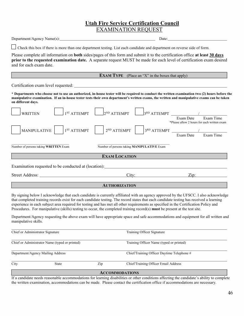
Utah Fire Service Certification Council EXAMINATION REQUEST
Department/Agency Name(s): Date: Check this box if there is more than one department testing. List each candidate and department on reverse side of form.
Please complete all information on both sides/pages of this form and submit it to the certification office at least 30 days prior to the requested examination date. A separate request MUST be made for each level of certification exam desired and for each exam date. EXAM TYPE (Place an “X” in the boxes that apply)
Certification exam level requested: * Departments who choose not to use an authorized, in-house tester will be required to conduct the written examination two (2) hours before the manipulative examination. If an in-house tester tests their own department’s written exams, the written and manipulative exams can be taken on different days. WRITTEN 1ST ATTEMPT 2ND ATTEMPT 3RD ATTEMPT / Exam Date Exam Time *Please allow 2 hours for each written exam MANIPULATIVE 1ST ATTEMPT 2ND ATTEMPT 3RD ATTEMPT / Exam Date Exam Time Number of persons taking WRITTEN Exam Number of persons taking MANIPULATIVE Exam
EXAM LOCATION
Examination requested to be conducted at (location): Street Address: City: Zip:
AUTHORIZATION By signing below I acknowledge that each candidate is currently affiliated with an agency approved by the UFSCC. I also acknowledge that completed training records exist for each candidate testing. The record states that each candidate testing has received a learning experience in each subject area required for testing and has met all other requirements as specified in the Certification Policy and Procedures. For manipulative (skills) testing to occur, the completed training record(s) must be present at the test site. Department/Agency requesting the above exam will have appropriate space and safe accommodations and equipment for all written and manipulative skills.
Chief or Administrator Signature Training Officer Signature
Chief or Administrator Name (typed or printed) Training Officer Name (typed or printed)
Department/Agency Mailing Address Chief/Training Officer Daytime Telephone #
City State Zip Chief/Training Officer Email Address
ACCOMMODATIONS If a candidate needs reasonable accommodations for learning disabilities or other conditions affecting the candidate’s ability to complete the written examination, accommodations can be made. Please contact the certification office if accommodations are necessary.
47
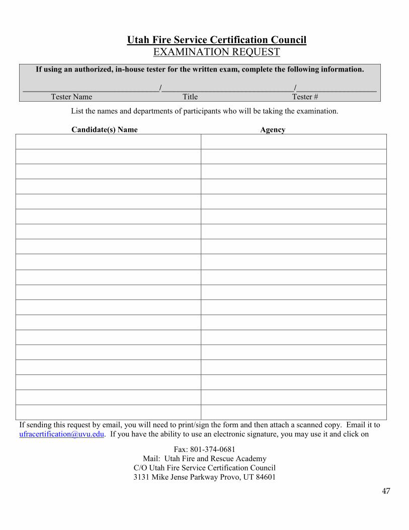
Utah Fire Service Certification Council EXAMINATION REQUEST
If using an authorized, in-house tester for the written exam, complete the following information.
__________________________________/_________________________________/____________________ Tester Name Title Tester #
List the names and departments of participants who will be taking the examination.
Candidate(s) Name Agency
If sending this request by email, you will need to print/sign the form and then attach a scanned copy. Email it to [email protected]. If you have the ability to use an electronic signature, you may use it and click on
Fax: 801-374-0681 Mail: Utah Fire and Rescue Academy
C/O Utah Fire Service Certification Council 3131 Mike Jense Parkway Provo, UT 84601
48
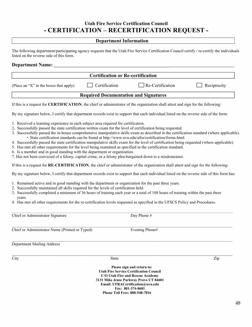
Utah Fire Service Certification Council - CERTIFICATION – RECERTIFICATION REQUEST -
Department Information The following department/participating agency requests that the Utah Fire Service Certification Council certify / re-certify the individuals listed on the reverse side of this form. Department Name: ___________________________________________________________________________________________
Certification or Re-certification (Place an “X” in the boxes that apply) Certification Re-Certification Reciprocity
Required Documentation and Signatures If this is a request for CERTIFICATION, the chief or administrator of the organization shall attest and sign for the following: By my signature below, I certify that department records exist to support that each individual listed on the reverse side of the form: 1. Received a learning experience in each subject area required for certification. 2. Successfully passed the state certification written exam for the level of certification being requested. 3. Successfully passed the in-house comprehensive manipulative skills exam as described in the certification standard (where applicable). State certification standards can be found at http://www.uvu.edu/ufra/certification/forms.html. 4. Successfully passed the state certification manipulative skills exam for the level of certification being requested (where applicable). 5. Has met all other requirements for the level being examined as specified in the certification standard. 6. Is a member and in good standing with the department or organization. 7. Has not been convicted of a felony, capital crime, or a felony plea-bargained down to a misdemeanor. If this is a request for RE-CERTIFICATION, the chief or administrator of the organization shall attest and sign for the following:
By my signature below, I certify that department records exist to support that each individual listed on the reverse side of this form has: 1. Remained active and in good standing with the department or organization for the past three years. 2. Successfully maintained all skills required for the levels of certification held. 3. Successfully completed a minimum of 36 hours of training each year or a total of 108 hours of training within the past three years. 4. Has met all other requirements for the re-certification levels requested as specified in the UFSCS Policy and Procedures. ______________________________________________________________________________________________________________________________________ Chief or Administrator Signature Day Phone # ___________________________________________________________________________________________________________ Chief or Administrator Name (Printed or Typed) Evening Phone# ___________________________________________________________________________________________________________ Department Mailing Address ___________________________________________________________________________________________________________ City State Zip
Please sign and return to:
Utah Fire Service Certification Council C/O Utah Fire and Rescue Academy
3131 Mike Jense Parkway Provo UT 84601 Email: [email protected]
Fax: 801-374-0681 Phone Toll Free: 888-548-7816
49
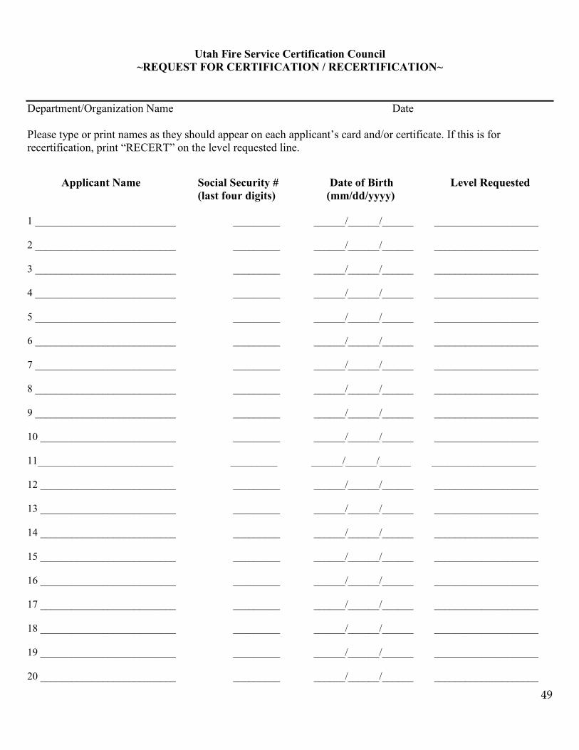
Utah Fire Service Certification Council ~REQUEST FOR CERTIFICATION / RECERTIFICATION~
Department/Organization Name Date Please type or print names as they should appear on each applicant’s card and/or certificate. If this is for recertification, print “RECERT” on the level requested line. Applicant Name Social Security # Date of Birth Level Requested (last four digits) (mm/dd/yyyy) 1 ___________________________ _________ ______/______/______ ____________________ 2 ___________________________ _________ ______/______/______ ____________________ 3 ___________________________ _________ ______/______/______ ____________________ 4 ___________________________ _________ ______/______/______ ____________________ 5 ___________________________ _________ ______/______/______ ____________________ 6 ___________________________ _________ ______/______/______ ____________________ 7 ___________________________ _________ ______/______/______ ____________________ 8 ___________________________ _________ ______/______/______ ____________________ 9 ___________________________ _________ ______/______/______ ____________________ 10 __________________________ _________ ______/______/______ ____________________ 11__________________________ _________ ______/______/______ ____________________ 12 __________________________ _________ ______/______/______ ____________________ 13 __________________________ _________ ______/______/______ ____________________ 14 __________________________ _________ ______/______/______ ____________________ 15 __________________________ _________ ______/______/______ ____________________ 16 __________________________ _________ ______/______/______ ____________________ 17 __________________________ _________ ______/______/______ ____________________ 18 __________________________ _________ ______/______/______ ____________________ 19 __________________________ _________ ______/______/______ ____________________ 20 __________________________ _________ ______/______/______ ____________________