Embed Size (px)
Citation preview
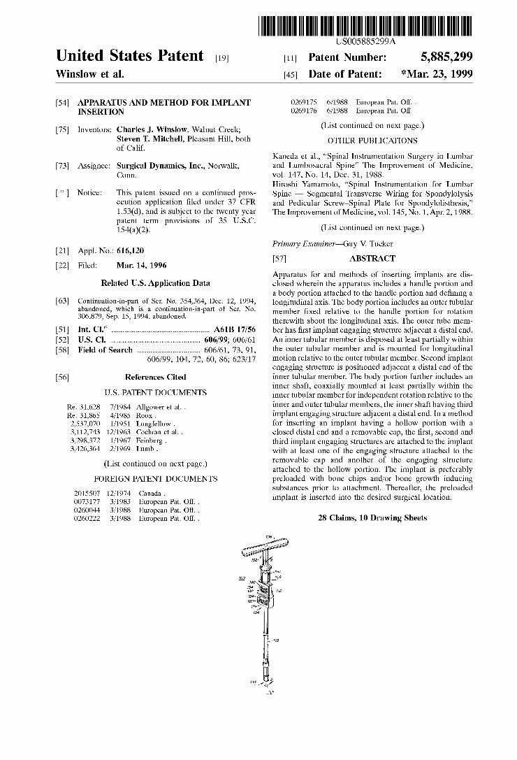
United States Patent [19] Winslow et al.
US005885299A
[11] Patent Number: 5,885,299 [45] Date of Patent: *Mar. 23, 1999
[54] APPARATUS AND METHOD FOR IMPLANT INSERTION
[75] Inventors: Charles J. Winslow, Walnut Creek; Steven T. Mitchell, Pleasant Hill, both of Calif.
[73] Assignee: Surgical Dynamics, Inc., Norwalk, Conn.
[*] Notice: This patent issued on a continued pros ecution application ?led under 37 CFR 1.53(d), and is subject to the tWenty year patent term provisions of 35 U.S.C. 154(a)(2).
[21] Appl. No.: 616,120
[22] Filed: Mar. 14, 1996
Related US. Application Data
[63] Continuation-in-part of Ser. No. 354,364, Dec. 12, 1994, abandoned, which is a continuation-in-part of Ser. No. 306,879, Sep. 15, 1994, abandoned.
[51] Int. Cl.6 ................................................... .. A61B 17/56
[52] US. Cl. ............................................... .. 606/99; 606/61
[58] Field of Search ................................ .. 606/61, 73, 91, 606/99, 104, 72, 60, 86; 623/17
[56] References Cited
U.S. PATENT DOCUMENTS
Re. 31,628 7/1984 Allgower et al. . Re. 31,865 4/1985 Roux . 2,537,070 1/1951 Longfellow . 3,112,743 12/1963 Cochran et al. .
3,298,372 1/1967 Feinberg . 3,426,364 2/1969 Lumb .
(List continued on next page.)
FOREIGN PATENT DOCUMENTS
2015507 12/1974 Canada. 0073177 3/1983 European Pat. Off. . 0260044 3/1988 European Pat. Off. . 0260222 3/1988 European Pat. Off. .
0269175 0269176
6/1988 European Pat. Off. . 6/1988 European Pat. Off. .
(List continued on next page.)
OTHER PUBLICATIONS
Kaneda et al., “Spinal Instrumentation Surgery in Lumbar and Lumbosacral Spine” The Improvement of Medicine, vol. 147, No. 14, Dec. 31, 1988. Hiroshi Yamamoto, “Spinal Instrumentation for Lumbar Spine — Segmental Transverse Wiring for Spondylolysis and Pedicular ScreW—Spinal Plate for Spondylolisthesis,” The Improvement of Medicine, vol. 145, No. 1,Apr. 2, 1988.
(List continued on next page.)
Primary Examiner—Guy V. Tucker
[57] ABSTRACT
Apparatus for and methods of inserting implants are dis closed Wherein the apparatus includes a handle portion and a body portion attached to the handle portion and de?ning a longitudinal axis. The body portion includes an outer tubular member ?xed relative to the handle portion for rotation therewith about the longitudinal axis. The outer tube mem ber has ?rst implant engaging structure adjacent a distal end. An inner tubular member is disposed at least partially Within the outer tubular member and is mounted for longitudinal motion relative to the outer tubular member. Second implant engaging structure is positioned adjacent a distal end of the inner tubular member. The body portion further includes an inner shaft, coaxially mounted at least partially Within the inner tubular member for independent rotation relative to the inner and outer tubular members, the inner shaft having third implant engaging structure adjacent a distal end. In a method for inserting an implant having a holloW portion With a closed distal end and a removable cap, the ?rst, second and third implant engaging structures are attached to the implant With at least one of the engaging structure attached to the removable cap and another of the engaging structure attached to the holloW portion. The implant is preferably preloaded With bone chips and/or bone groWth inducing substances prior to attachment. Thereafter, the preloaded implant is inserted into the desired surgical location.
28 Claims, 10 Drawing Sheets

5,885,299 Page 2
US. PATENT DOCUMENTS 4.877.020 10/1989 Vich - 4,878,915 11/1989 Brantigan.
3,486,505 12/1969 Morrison. 4,904,260 2/1990 Ray. 3,514,791 6/1970 Sparks . 4,904,261 2/1990 DOVe 6t 61- - 3,625,198 12/1971 Sparks . 4,927,421 5/1990 Goble et al. . 3,719,186 3/1973 Merig, Jr. . 479367848 6/1990 Bagby - 3 720 959 3/1973 Hahn ' 4,936,851 6/1990 Fox et al. .
’ ’ . 4 950 270 8/1990 Bowman et al. . 3,783,860 1/1974 Burste1n et al. . 4’961’740 10/1990 Ray et a1_ _ 3,848,601 11/1974 Ma et al- - 5’015’247 5/1991 Michelson. 3,849,805 11/1974 Leake er al- - 5,015,255 5/1991 Kuslich. 3,852,045 12/1974 Wheeler et al. . 5,026,373 6/1991 Ray et a1_ _ 3,855,638 12/1974 Pilliar. 5055104 10/1991 Ray _ 3,867,728 2/1975 Stubs'tad et al. . 5’O59’193 “V1991 Kuslich ' 3,871,031 3/1975 B9119“ - 5,062,845 11/1991 Kuslich et al. . 3,905,047 9/1975 L‘mg- 5 139 499 8/1992 Small et al.. 3,906,550 9/1975 Rostoker et al. . 5,147,402 9/1992 Bohler et a1_ _ 3,916,907 11/1975 Peterson. 5,195,541 3/1993 obenchain_ 3,986,212 10/1976 Sauer. ’ ’
4,013,071 3/1977 Rosenberg. EZEELZ 4,016,651 4/1977 Kawahara et al. . 5’313’962 5/1994 Obenchain _ 4,059,115 11/1977 Jumashev et al. . 5’354’302 1O/1994 KO _ 4,086,701 5/1978 Kawahara 6‘ al- - 5,357,983 10/1994 Mathews . 4,124,026 11/1978 BefIleT et a1- - 5,358,511 10/1994 Gatturna et al. . 4,177,524 12/1979 Grell et al. . 5 400 805 3/1995 Warren _ 4,180,910 1/1980 Straumann et al. . 5,423,817 6/1995 Lin _ 4,185,383 1/1980 Heimke et al. . 5’425’772 6/1995 Brantigon ' 4,259,072 3/1981 Hirabayashi et al. . 5,425,773 6/1995 Boyd et a1_ _ 4,289,123 9/1981 Dnnn . 5,439,464 8/1995 Shapiro . 4,309,777 1/1982 Patll - 5,445,639 8/1995 Kuslich et al. . 4,328,593 5/1982 Sutter et al. . 5 454 811 10/1995 Huebner _
4,349,921 9/1982 Kuntz . 5,458,638 10/1995 Kuslich et al. . 4.401.112 8/1983 Relalan - 5,470,334 11/1995 Ross et al. . 4,406,623 9/1983 Grafelmann et al. . 5 480 403 1/1996 Lee et aL _
jajgiaggg 153132: lg’lll‘itnecrha a1 5,484,437 1/1996 Michelson. 474927226 1/1985 Belykh et all I 5,489,308 2/1996 Kushch et al. .
4,493,317 1/ 1985 Klaue ~ FOREIGN PATENT DOCUMENTS 4,501,269 2/1985 Bagby . 4,511,336 4/1985 Hidaka et al. . 2 295 729 12/1974 France . 4,513,744 4/1985 Klaue . 1 961 531 7/1970 Germany . 4,522,200 6/1985 Stednitl - 3505567 6/1986 Germany. 4,525,145 6/1985 Scheicher et al. . 56-34731 8/1981 Japan . 4,537,185 8/1985 StednitZ . 57-29348 2/1982 Japan _ 4,545,374 10/1985 Jacobson. 58-78653 5/1983 Japan. 4,549,319 10/1985 Meyer- 61-135652 6/1986 Japan. 4,553,273 11/1985 W11 - 62-164458 7/1987 Japan. 4,569,338 2/1986 Edwards. 63-43654 2/1988 Japan. 4,573,448 3/1986 Kambin - 63-158045 7/1988 Japan. 4,599,084 7/1986 Nashef- 1-502402 8/1989 Japan. 4,599,086 7/1986 D°tY~ 1-314560 12/1989 Japan. 4,611,581 9/1986 Steffee. 283078 2/1985 Spain. 4,636,217 1/1987 Ogilvie er al- - W0/86/03666 7/1986 WIPO . 4,653,481 3/1987 Howland et al. . 8803781 6/1988 WIPO _ 4,653,486 3/1987 Coker- W0/89/09035 10/1989 WIPO 4,655,199 4/1987 Steffee . 9000037 1/1990 WIPO 4,657,550 4/1987 Daher. 4,662,891 5/1987 Noiles . OTHER PUBLICATIONS 4,673,409 6/1987 Van Kampen . 4,677,97 7/1987 Tornier . Shibata et al., “A NeW Conrivance of Anterior Spinal Fusion 4,714,469 12/1987 Kenna - in Cervical Spine”, Orhopaedic and Traumatic Surgery, vol. 4.721.103 1/1988 Freedland - 35, No. 3, pp. 811—813, 1987.
liiiiggis'ek _ Haruo Tsuji,“Anterior Body Fusion of Lumbar Spine Her 4’743’256 5/1988 Brantigan _ n1a”, Operat1on, vol. 41, No. 11, pp. 1803—1811, 1987. 4,743,260 5/1988 Burton - Hirotugu Oda et al., “Osteoplastic—Hemi/Bilater Partial 4,759,768 7/1988 Hermann et al' - Laminectomy of Lumbar Spinal Hernia”, Operation, vol. 41,
gfyrfche“ No. 11, pp. 1785—1791, 1987. 4:790:297 12/1988 Luque _ Teiji Yano et al., “Treatment of Spondylolisthesis by Poste 4,790,303 12/1988 Steffee. rior Fusion With Bone Grafting to Neural Arch Defect”, 4,802,468 2/1989 POWIHII - Clinical Orthopaedic Surgery, vol. 17, No. 4, pp. 394—399, 4,820,305 4/1989 Harms et al. . 1982'
£22255; 'et aL _ Toshihiko Yamane, et al., “A case Report of Multiple Lum 4’863’430 9 /1989 Klyce et a1_ _ bar Spondylolyses W1th Spondylol1sthes1s”, Cl1n1cal Ortho 4,863,474 9/1989 Brown et al. . paedic Surgery, vol. 23, No. 3, pp. 311—314, 1988.

5,885,299 Page 3
M. Maeshiro, et al., “Posterior Fracture Dislocation of the Thoracic Spine: Two Cases Report”, Orthopaedic Surgery, vol. 39, No. 9, pp. 1373—1377, 1988—1989. Kunio Takaoka, “Clinical Application of Ceramic Implants in Orthopaedic Surgery”, Medicina philosophica, vol. 4, No. 7, pp. 546—552, 1985. Y. Yamano et al., “Anterior Body Fusion of Lumbar Degen erative Spondylolisthese”, Journal of the Western Japanese Research Society For Spine, vol. 13, pp. 46—50. “Dual Chisel and Its Bank Bones (Skimud Subkortikate Bones) for Posterior Lumbar Interbody Fusion — In Order to Simplify and RegulariZe the Surgical Procedure”, Ortho paedic Surgery, vol. 11, pp. 150—153, (Author Unknown). “Vertebral Body Distraction System (Caspar)”, Orthopaedic Surgery, vol. 11, pp. 135—139, (Author Unknown). Takayoshi Ueda et al., “Instrumentation Surgery of Lumbar Interbody Fusion”, Central Japan Journal of Orthopaedic and Traumatic Surgery, pp. 87—89. Haruo Tsuji et al., “Development and Clinical Application of Arti?cial Intervertebral Disc for Cervical Disc Lesions”, Central Japan Journal of Orthopaedic & Traumatic Surgery, pp. 1505—1506. Benjamin R. Witberger, M.D., “Intervertebral Body Fusion By The Use Of Posterior Bone Dowel”, Clinical Ortho paedics, 35:69—79, 1964. “Gewebsreaktion auf ein Titan—HohlZylinderimpantat mit Titan—SpritZschichtober?ache”, by A. Schroeder, O. Pohler and F. Sutter, Separatdruck aus: SchweiZ. Mschr. Zahnheilk vol. 86, No. 7, pp. 713—727, 1976. “Osseointegrated Titanium Implants, Requirements for Ensuring a Long—Lasting, Direct Bone—to—Implant Anchor age in Man”, by T. Albrektsson et al., Acta Orthop. Scand., vol. 52, pp. 155—170, 1981. “The Reactions of Bone, Connective Tissue, and Ephithe lium to Endosteal Implants With Titanium—Sprayed Sur faces”, by Andre Schroeder et al., J. maX.—fac. Surg. 9, pp. 15—25, 1981. “Neue Rekonstruktionsmoglichkeiten bei Unterkiefrdefek ten nach Tummorresektion”, by J. Raveh et al., Separatdruck aus: SchweiZ. Mschr. Zahnheilk vol. 91, Nr. 11, pp. 899—920, 1981. “Cementless FiXation of Polyethylene Acetabular Compo nent in Total Hip Arthroplasty”, by E. W. Morscher et al., Archives of Arthopaedic and Tumatic SUrgery, vol. 99, Issue 4, pp. 223—230, 1982. “Neue Rekonstruktionsmoglichkeiten des Unterkiefers bei knochernen Defekten nach Tumorresektionen”, by J. Raueh et al., Chirurg, vol. 53, pp. 459—467, 1982. “New Concepts in the Reconstruction of Mandibular Defects Following Tumor Resection”, by. Y. Reveh, M.D., DMD, et al., J Oral MaXillofaX Surg, vol. 41, Issue 1, pp. 3—16, Jan. 1983. “Use of the Titanium Coated Hollow Screw and Reconstruc tion Plate System in Bridging Lower Jaw Defects”, by J. Raveh, et al., J. Oral MaXillofac Surg., vol. 42, Issue 5, pp. 281—294, May 1984. “Titanplasma—beschichtetes Holschrauben—und Rekon struktions—platten—System (THRP) Zur Uberbriickung von Kieferdefekten”, by F. Sutter et al., Chirurg, vol. 55, Issue 1, pp. 741—748, Nov. 1984. “Titanplasma—beschichtetes Hohlschrauben—und Rekon struktionsplatten—System (THRP) Zur Uberbriickrung von Kieferdefekten”, by F. Sutter et al., Chirurg, vol. 56, Issue 5, pp. 337—344, May 1985.
“Anterior Cervical Interbody Fusion With Threaded Cylin drical Bone”, by Jose M. Otero Vich, M.D., J. Neurosurg, vol. 63, pp. 750—753, Nov., 1985. “Die vordere Verplattung der Halswirbelsaule mit dem Hohlschrauben—Plattensystem aus Titanium”, by E. Mor scher et al., Chirurg, vol. 57, Issue 11, pp. 702—707, 1986. “Surgical Procedures for Reconstruction of the Lower Jaw Using the Titanium—Coated Hollow—Screw Reconstruction Plate System: Bridging of Defects”, by J. Raveh et al., The Otolaryngologi Clinics of North America, vol. 20, No. 3, pp. 535—558, Aug., 1987. “Titanium Coated Hollow Screw and Reconstruction Plate System For Bridging of Lower Jaw Defects: Biomechanical Aspects”, by F. Sutter et al., Int. J. Oral MaXillofac. Surg., vol. 17, Issue 4, pp. 267—274, 1988. Arthrodesis By The Distraction—Compression Method Using AStainless Steel Implant, by George W. Bagby, M.D., M.S., Orthopedics, vol. 11, pp. 931—934, Jun. 1988. Engineering and Design Aspects of the I.T.I. Hollow—Basket Implants, by F. Sutter, D.D.S., et al., Journal of Oral Implan tology, pp. 535—551, 1983. American Journal of Veterinarian Research, Author: Unknown, vol. 45, No. 1, Jan. 1984, pp. 195—199. “Posterior Lumbar Interbody Fusion Made Simple”, by G. M. Sava, Neurological Surgery Associates of Cincinnati, Inc., 2 pages, undated. Surgical Titanium Mesh Ordering Information, DePuy Motech, Warsaw, Indiana, USA, 2 pages, undated. Cage CH — Lumbar spacing cages, Scient’X, Paris, France, 4 pages, undated. “Basket Implant Facilitates Spinal Fusion”, Orthopedics Today, vol. 7, No. 10, Oct. 1987, p. 4. Norman W. Hoover, M.D., “Methods of Lumbar Fusion”, The Journal of Bone and Joint Surgery, Jan. 1968, pp. 194—210. Shun—Ichi Inque, M.D., Ph.D., et al., “Anterior Discectomy and Interbody Fusion for Lumbar Disc Herniation”, Lumbar Disc Herniation, vol. 183, Mar. 1984, pp. 22—31. A. Kumar, M.D., et al., “Interspace Distraction and Graft Subsidence After Anterior Lumbar Fusion With Femoral Strut Allograft”, Spine vol. 18, No. 16, pp. 2392—2400, 1993. Charles V. Burton, “Fusion: What It’s Been and Where It’s Going”, The International Society for the Study of the Lumbar Spine, The Lumbar Spine, Chapter 23, pp. 998—1003. Keith H. Bridwell, M.D., “Normal Sagittal Alignment”, Federation of Spine Associations, Section IV — Scoliosis Research Society, Sagittal Spinal Balance —Symposium No. 1, Feb. 27, 1994. Charles G. Hutter, “A Technique for Posterior Lumbar Interbody Fusion”, Chapter 19, Lumbar Interbody Fusion, 1989, pp. 227—232. S+G Implants, S+G Spongiosametall Liibeck, Blocke Typ Waisbrod, 2 pages, Author and Date Unknown. S+G Implants, S+G Cast Cancellous Metal, PLIF (Posterior Lumbar Interbody Fusion) with Cast Cancellous Metal Mould (CCMM), 4 pages, Author and Date uknown. Cage, CR, Cerivical Spacing Cages, Cages Intersomatiques Cervicales, Scient’X, Paris, 1 page. Actualités Vertébrales, La Hernie Discale Cervicale, No. 2, Avril 994, 11 pages. Cage CH — Lumbar spacing cages, Scient’X, Paris, France, 4 pages undated.
U.S. Patent Mar. 23, 1999 Sheet 1 0f 10 5,885,299
702 /
I54
[108 152
146 1 720 I3 4
V

U.S. Patent Mar. 23, 1999 Sheet 2 0f 10 5,885,299

U.S. Patent Mar. 23, 1999 Sheet 3 0f 10 5,885,299
m 2

U.S. Patent Mar. 23, 1999 Sheet 4 0f 10 5,885,299
/E_ 5

U.S. Patent Mar. 23, 1999 Sheet 5 0f 10 5,885,299
710 /E_ 5
118
O \\\\\\ 128/ 115
142 212
5 49.4,,


U.S. Patent Mar. 23, 1999 Sheet 7 0f 10 5,885,299
/E_ 5A
v O m

U.S. Patent Mar. 23, 1999 Sheet 8 0f 10 5,885,299
QQNIIPU§ \ w:
\ _| _ E ____ . 5 .
w9\ A. . . ./___.
on“ \ Fa
m9 NM“ 9N“ NE 9w m: oww
m
Ill /// // ll- ,
.l .\\\\\\\\\ , . _
I II . ~
\ \
Q: 0'2 m: pm“ “.3 WWW EN
{UN |m\U\
Q: WNW
VON
VNN

U.S. Patent Mar. 23, 1999 Sheet 9 0f 10 5,885,299
770
/E'_ .11
300
A

U.S. Patent Mar. 23, 1999 Sheet 10 0f 10 5,885,299

5,885,299 1
APPARATUS AND METHOD FOR IMPLANT INSERTION
This application is a continuation-in-part of US. appli cation Ser. No. 08/354,364, ?led on Dec. 12, 1994, abandoned, Which is a continuation-in-part of US. applica tion Ser. No. 08/306,879, ?led on Sep. 15, 1994, noW abandoned. The contents of these applications are incorpo rated herein by reference.
BACKGROUND
1. Technical Field
This disclosure relates generally to apparatus and methods for implant insertion. More particularly, to apparatus and methods for insertion of implants to facilitate fusion of adjacent bony structure.
2. Background of the Related Art A large number of orthopedic procedures involve the
insertion of either natural or prosthetic implants into bone or associated tissues. These procedures include, for eXample, ligament repair, joint repair or replacement, non-union fractures, facial reconstruction, spinal stabiliZation and spi nal fusion. In a typical procedure, an insert, doWel or screW is inserted into a prepared bore formed in the bone or tissues to facilitate repair and healing. See, for example, US. Pat. No. : 5,470,334 to Ross et al.; US. Pat. No. 5,454,811 to Huebner; US. Pat. No. 5,480,403 to Lee et al.; US. Pat. No. 5,40,805 to Warren; US. Pat. No. 5,358,511 to Gatturna et al.; and US. Pat. No. 4,877,020 to Vich. Some implants are particularly con?gured With cavities
and bores to facilitate bony ingroWth and enhance anchoring of the implant at the insertion site. See, for example, US. Pat. No. : 4,328,593 to Sutter et al.; US. Pat. No. 4,936,851 to FoX et al.; and US. Pat. No. 4,878,915 to Brantigan. Implants in the form of fusion cages having internal cavities to receive bone groWth stimulation materials such as bone chips and fragments are disclosed, for example, in US. Pat. No. : 4,501,269 to Bagby; US. Pat. No. 4,961,740 to Ray et al.; US. Pat. No. 5,015,247 to Michaelson; and US. Pat. No. 5,489,307 to Kuslich et al. These types of implants are particularly Well suited for intervertebral spinal fusion pro cedures necessitated by injury, disease or some degenerative disorder of the spinal disc. Subsequently, there may be progressive degeneration leading to mechanical instability betWeen adjacent vertebrae necessitating direct fusion of the vertebrae While maintaining a pre-de?ned intervertebral space. This fusion may be accomplished by the insertion of one or more of the specialiZed implants as discussed above and also discussed in commonly assigned US. Pat. No. 5,026,373, incorporated herein by reference.
Both anterior (transabdominal) and posterior surgical approaches are used for interbody fusions of the lumbar spine. Fusions in the cervical area of the spine are primarily done using an anterior approach. Typically, an implant such as a plug, doWel, prosthesis or cage is inserted into a preformed cavity inside the interbody, interdiscal space. Since it is desirable in these procedures to promote a “bone to bone” bridge, connective tissue and at least a portion of the discal tissue is removed. Preferably, relatively deep cuts are made in the adjacent bones in order to penetrate into the softer, more vasculariZed cancellous region to facilitate bone groWth across the implant. When installing these specialiZed implants, an insertion
tool is used to position the implant in the desired interver tebral location. See, for example, US. Pat. No.: 3,848,601 to Ma et al.; US. Pat. No. 4,501,269 to Bagby; US. Pat. No.
10
15
20
25
30
35
40
45
50
55
60
65
2 4,877,020 to Vich; and US. Pat. No. 4,878,915 to Brantigan. Once in position, the insertion tool is removed and, Where the implant structure permits, bone chips or other bone groWth inducing substances are packed into the implant in vivo. Subsequently, an end cap or other sealing structure is positioned to close the implant. See, for eXample, commonly assigned US. Pat. No. 4,961,740 to Ray et al. incorporated herein by reference.
Typical insertion tools use either a single implant engage ment structure or, at most, tWo implant engagement struc tures to facilitate positioning of the implant. For eXample, in US. Pat. No. 4,501,269 to Bagby, prongs are used to engage the implant. In US. Pat. No. 4,878,915 to Brantigan and US. Pat. No. 5,015,247 to Michaelson, a threaded rod and slot are used to engage the implant In US. Pat. No. : 4,961,740 to Ray et al.; US. Pat. Nos. 5,489,308 and 5,489,307, both to Kuslich et al.; and US. Pat. No. 4,936, 838 to Bagby, a single central shaft is used. In all of these insertion tools, no structure is provided to permit the inser tion tool to attach to an outer peripheral portion of the implant, either in vitro or in vivo. Further, these tools do not provide structure Which separately engages both the implant and the implant closure, eg an end cap.
Accordingly, a need eXists for an insertion tool Which is capable of either inserting an implant preloaded With bone chips, etc. Such in vitro packing facilitates the surgical procedure because it is often time consuming and relatively dif?cult, especially for eXample in cervical applications, to pack the cage in vivo. It Would also be advantageous if such insertion tool could be additionally used to insert/position an empty implant for subsequent in vivo packing and closure.
SUMMARY
Apparatus for and methods of inserting implants are disclosed Wherein the apparatus includes a handle portion and a body portion attached to the handle portion and de?ning a longitudinal aXis. The body portion includes an outer tubular member ?Xed relative to the handle portion for rotation thereWith about the longitudinal aXis. The outer tubular member has ?rst implant engaging structure adjacent a distal end. An inner tubular member is disposed at least partially Within the outer tubular member and is mounted for longitudinal motion relative to the outer tubular member. Second implant engaging structure is positioned adjacent a distal end of the inner tubular member. The body portion further includes an inner shaft, coaXially mounted at least partially Within the inner tubular member for independent rotation relative to the inner and outer tubular members, the inner shaft having third implant engaging structure adjacent a distal end.
In a method for inserting an implant having a holloW portion With a closed distal end and a removable cap, the ?rst, second and third implant engaging structures are attached to the implant With at least one of the engaging structures attached to the removable cap and another of the engaging structure attached to the holloW portion. The implant is preferably preloaded With bone chips and/or bone groWth inducing substances prior to attachment Thereafter, the preloaded implant is inserted into the desired surgical location.
BRIEF DESCRIPTION OF THE DRAWINGS
Various embodiments of the subject implant insertion apparatus are described beloW With reference to the draW ings Wherein:
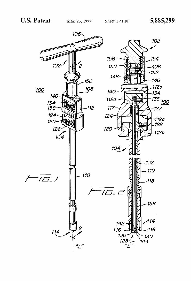
FIG. 1 is a perspective vieW of an implant insertion apparatus constructed in accordance With a preferred embodiment of the subject disclosure:
5,885,299 3
FIG. 2 is a side vieW in cross-section of the implant insertion apparatus taken along line 2—2 of FIG. 1;
FIG. 2A is an enlarged side vieW in cross-section of the connection betWeen the handle portion and the body portion of the implant insertion apparatus of FIG. 1;
FIG. 2B is an enlarged perspective vieW of the distal ends of the outer and inner tubular members of the implant insertion apparatus of FIG. 1;
FIG. 2C is an enlarged perspective vieW of an inter changeable distal end of the outer tubular member of the implant insertion apparatus of FIG. 1;
FIG. 3 is an enlarged perspective vieW of one type of implant con?gured for interbody fusion;
FIG. 4 is an enlarged proximal end vieW of the implant of FIG. 3 illustrating the structure of the removable end cap;
FIG. 5 is an enlarged end vieW in cross-section of the implant taken along line 5—5 of FIG. 3.
FIG. 6 is an enlarged perspective vieW of the implant of FIG. 3 With parts separated and loading of bone chips in process;
FIG. 6A is a side vieW in partial cross-section shoWing an end cap mounted to the inner tubular member and the inner shaft;
FIG. 7 is a perspective vieW of a preloaded implant With removable end cap in place;
FIG. 8A is an enlarged side vieW in partial cross-section illustrating the distal end of the implant insertion apparatus of FIG. 1 and the implant of FIG. 7;
FIG. 8B is an enlarged side vieW of the housing and rotation Wheels of the body portion illustrating the relative position of the inner tubular member as shoWn in FIG. 8A;
FIG. 9A is an enlarged side vieW in partial cross-section illustrating the distal end of the implant insertion apparatus of FIG. 1 With the second and third implant engagement structure attached to the removable cap of the implant of FIG. 7;
FIG. 9B is an enlarged side vieW of the housing and rotation Wheels of the body portion illustrating the relative position of the inner tubular member and the inner shaft as shoWn in FIG. 9A;
FIG. 10A is an enlarged side vieW in partial cross-section illustrating the distal end of the implant insertion apparatus of FIG. 1 With the ?rst, second and third implant engagement structure attached to the implant of FIG. 7;
FIG. 10B is an enlarged side vieW of the housing and rotation Wheels of the body portion illustrating the relative position of the inner shaft, the inner tubular member and the outer tubular member as shoWn in FIG. 10A;
FIG. 11 is a side vieW illustrating the insertion of the implant of FIG. 7 using the insertion apparatus of FIG. 1; and
FIG. 12 is an enlarged top vieW in partial cross-section of a pair of implants in place in the intervertebral space of a lumbar spinal section.
DETAILED DESCRIPTION OF PREFERRED EMBODIMENTS
The preferred embodiments of the apparatus and methods disclosed herein are discussed in terms of orthopedic spinal fusion procedures and apparatus. It is also envisioned, hoWever, that the disclosure is applicable to a Wide variety of procedures including, but not limited to ligament repair, joint repair or replacement, non-union fractures, facial reconstruction and spinal stabiliZation. In addition, it is
10
25
35
45
55
65
4 believed that the present apparatus ?nds application in both open and minimally invasive procedures including endo scopic and arthroscopic procedures Wherein access to the surgical site is achieved through a cannula or small incision.
In the description Which folloWs, the term “proximal”, as is traditional, Will refer to the portion of the structure Which is closer to the operator, While the term “distal” Will refer to the portion Which is further from the operator.
Referring noW in detail to the draWings in Which like reference numerals identify similar or identical elements, a preferred embodiment of the implant insertion apparatus is illustrated in FIGS. 1 and 2 and is designated generally by reference numeral 100. Implant insertion apparatus 100 includes a removable handle portion 102 and a body portion 104. Handle portion 102 has a T-handle 106 positioned at a proximal end and releasable engagement structure 108 at a distal end thereof. Body portion 104 de?nes a longitudinal axis “L” and
includes an outer tubular member 110 ?xed to a housing 112 for longitudinal rotation thereWith. First implant engaging structure 114 is positioned adjacent a distal end of outer tubular member 110. Outer tubular member 110 preferably includes a removable distal end portion 158 described beloW. In the embodiment shoWn, the implant engaging structure is a pair of distally extending tabs 116 projecting from the distal end of outer tubular member 110. Body portion 104 further includes an inner tubular mem
ber 118 disposed at least partially Within outer tubular member 110. Inner tubular member 118 is mounted for limited longitudinal motion relative to outer tubular member 110 and is independently rotatable relative to outer tubular member 110 by Wheel 120. In the illustrated embodiment, set screW 122 anchors Wheel 120 to the inner tubular member 118. A?rst cavity 124 is de?ned in housing 112 and is dimensioned to limit the relative longitudinal motion of inner tubular member 118 by con?ning Wheel 120 betWeen Walls 112a, 112b. As shoWn in FIG. 1, the periphery of Wheel 120 may be provided With knurling 126 to enhance its frictional characteristics.
Inner tubular member 118 is normally biased to a distal most longitudinal position relative to outer tubular member 110 as shoWn in FIG. 2. Coil spring 127, mounted in housing 112, abuts a proximal end of inner tubular member 118 and biases inner tubular member distally. Second implant engag ing structure 128 is formed adjacent a distal end of the inner tubular member 118. In the illustrated embodiment, the second implant engaging structure 128 is a holloW polygonal structure having a plurality of ?at sides 130 extending from the distal end of inner tubular member 118. Body portion 104 also includes an inner shaft 132, coaxi
ally mounted at least partially Within the inner tubular member 118. Inner shaft 132 is longitudinally rotatable relative to inner tubular member 118 and outer tubular member 110 by Wheel 134. As shoWn, set screW 136 connects Wheel 134 to a distal end of inner shaft 132. In a preferred embodiment, the outer periphery of Wheel 134 is provided With a friction enhancing surface such as knurling 138. A second cavity 140 is de?ned in housing 112 proximal to
?rst cavity 124 and serves to con?ne Wheel 134, and thus inner shaft 132, to limited longitudinal motion relative to outer and inner tubular members 110 and 118, respectively betWeen Walls 112c, 112d. Wheels 120 and 134 preferably extend radially beyond at least one outer peripheral surface of house 112 to facilitate actuation by the ?ngers of a user.
Inner shaft 132 has third implant engaging structure 142 positioned adjacent a distal end (See FIGS. 2 and 6A). In the

5,885,299 5
illustrated embodiment, this structure is threads 144 formed on a distal end of inner shaft 132.
Referring noW to FIGS. 2 and 2A, releasable engagement structure 108 of the illustrated embodiment of implant insertion apparatus 100 includes a distal sleeve 146 having an inner surface con?gured to engage hexagonal projection 148 formed on a proximal end of housing 112.
Proximal sleeve 150 is operatively associated With distal sleeve 146 and includes an internal spring loaded ball system 152 con?gured to releasably engage an annular channel 154 Which extends proximally from hexagonal projection 148. Proximal sleeve 150 is mounted on a distal end of handle portion 102 for relative longitudinal motion betWeen a locked position (FIG. 2) and an unlocked position (FIG. 2A). In the locked position, ball system 152 is forced radially inWard into annular channel 154. Spring 156 nor mally biases proximal sleeve 150 into this locked position. As shoWn in FIG. 2A, in the unlocked position, proximal sleeve 150 is retracted to release ball system 152 from annular channel 154. This enables the removal of handle portion 102 from the body portion 104 so the handle portion can be attached to and used With other instrumentation necessary for performing the surgical procedure.
Referring to FIGS. 2B and 2C in vieW of FIG. 1, a versatile feature of the illustrated embodiment is shoWn. In this preferred embodiment, a distal end portion 158 of outer tubular member 110, Which contains ?rst implant engage ment structure 114, is interchangeably attached via a friction ?t. This alloWs the user to position another distal end portion 160, such as that shoWn in FIG. 2C, mounting either a different size (eg diameter) implant or con?guration of implant engagement structure on the same implant insertion apparatus. Thus, the insertion apparatus can be readily adapted to insert different implants. An implant designed for use in spinal fusion procedures
is shoWn in FIGS. 3—5 and designated generally by the reference number 200. This implant is commonly referred to as a “fusion cage” and, in this embodiment, is speci?cally con?gured for a posterior access spinal fusion procedure. Subsequent discussion regarding an exemplary use of the implant insertion tool 100 Will be focused on this posterior spinal fusion procedure inserting fusion cage 200. It is contemplated, hoWever, that the disclosed implant insertion tool has broad application in a Wide variety of implant insertion procedures beyond either anterior or posterior spinal fusion.
Fusion cage 200 includes a body portion 202 With a closed distal end 204 and a proximal end 206. The distal end 204 is rounded or bull nosed to facilitate insertion of the fusion cage 200 relative to one or more bone structures. The
proximal end 206 de?nes an opening 208 (FIG. 6) Which communicates With an internal cavity 210 (FIG. 5) de?ned by fusion cage 200. In the illustrated embodiment, opening 208 is threaded to receive an end cap 212. This end cap 212 is used to close off the proximal end 206 and to retain bone groWth inducing substances, such as bone chips 214 (FIG. 6), packed therein.
Referring to FIG. 4, end cap 212 de?nes a threaded bore 216 Which is con?gured to receive third implant engaging structure 142 of inner shaft 132 as Will be discussed in further detail beloW. End cap 212 also de?nes a substantially square depression 218 coaxial With thread bore 216 and con?gured to receive second implant engaging structure 128 on inner tubular member 118.
The proximal end 206 further de?nes ?rst and second peripheral indentations 220, 222 Which are centered about
10
15
25
35
45
55
65
6 transverse axis “T”. These peripheral indentations 220, 222 are con?gured to receive ?rst implant engagement structure 114, in this case tabs 116. These indentations may also be used to line up the fusion cage 200 for proper insertion and placement betWeen the adjacent vertebral structure. A helical thread 224 is formed on the outer peripheral
surface of the fusion cage 200. A plurality of apertures 226 are de?ned by and extend through the fusion cage 200. In the illustrated fusion cage 200, apertures 226 are formed by broaching grooves 228 (FIG. 5) in the internal surface 230 of internal cavity 210. This technique removes material from the valleys betWeen the turns of the thread 224, thus de?ning apertures 226 to advantageously provide immediate contact betWeen the vertebral body and the bone chips located inside the cage When the cage is positioned in the body.
Referring noW to FIGS. 6, 6A and 7, tWo methods of closing the end cap 212 in the opening 208 of proximal end 206 are illustrated. In FIG. 6, bone chips 214 are deposited into internal cavity 210 using forceps. Thereafter, end cap 212 can be manually threaded into opening 208 either by hand or With a socket Wrench-type instrument. Alternatively, end cap 212 can be positioned into engagement With second and third implant engaging structure 128, 142 of implant insertion apparatus 100. This is done by positioning the ?at sides 130 of second implant engaging structure 128 into square depression 218 of end cap 212. The distal end of inner shaft 132 is then threaded into bore 216 of end cap 212 by rotating Wheel 134 (FIG. 1). End cap 212 is then securely engaged by the second and third implant engaging structure 128, 142. The implant insertion apparatus 100 is positioned With the engaged end cap 212 in juxtaposed axial alignment With opening 208 in proximal end 206 of fusion cage 200. Rotation of Wheel 120 threads the end cap 212 into the fusion cage 200. As shoWn, in both methods, packing of the cage occurs outside the body. This facilitates insertion of bone chips since the chips are individually placed With a forceps and lightly tapped, e.g., compacted, inside the cage. This is especially advantageous Where access to the cage once implanted is limited and/or With smaller cages such as in cervical applications.
Mounting a packed fusion cage (FIG. 7) onto the insertion apparatus 100 and subsequent insertion into an intervertebral space Will noW be described With reference to FIGS. 8 through 12. In FIGS. 8A and 8B, the packed fusion cage is positioned in axial alignment With the proximal end of fusion cage 200, aligning tabs 116 With indentations 220, 222; ?at sides 130 With square depression 218; and threads 144 With threaded bore 216.
Referring noW to FIGS. 9A, 9B, 10A and 10B, fusion cage 200 is moved initially into engagement With inner tubular member 118 such that ?at sides 130 are disposed in square depression 218 of end cap 212. Further proximal motion (indicated by the arroWs in FIGS. 9A and 9B) of inner shaft 118 relative to inner shaft 132 by either pressing cage 200 against the apparatus or moving Wheel 120 proximally brings threads 144 into engagement With threaded bore 216 and tabs 116 of outer tubular member 110 into simultaneous engagement With indentations 220 and 222. (FIG. 10A) Wheel 120 can be slightly rotated to ensure alignment of tabs 116 and indentations 220, 222. Then, Wheel 134 is rotated to cause the threaded inner shaft to engage the fusion cage 200 by end cap 212 thus securely mounting the fusion cage 200 on the distal end of the implant insertion apparatus 100 as the cage 200 is pulled proximally via the engagement of the threads.
Thereafter, the implant insertion apparatus 100 is posi tioned adjacent the implant site (FIG. 11) Which typically

5,885,299 7
includes a pretapped bore formed in an intervertebral space between tWo adjacent vertebra. (Alternately, the fusion cage could be self-tapping.) The implant insertion apparatus 100 may be guided into position using a cannula or C-retractor 300 to facilitate accurate insertion of fusion cage 200. The T-handle 106 is then rotated to rotate outer tubular member 110 to engage threads 224 of the fusion cage 200 (shoWn in phantom) in the intervertebral space 302.
Once the fusion cage 200 is in position, Wheel 134 is rotated to disengage threads 144 from threaded bore 216. This releases the implant insertion apparatus 100 from the implanted fusion cage 200. (FIG. 12)
Note that since the fusion cage 200 is grasped and inserted by the apparatus 100 from its open end, once positioned inside the body, the end cap 212 can be removed if the user desires to vieW or access the bone chips in the internal cavity 210.
The implant insertion apparatus 100 can also be utiliZed to insert an empty implant such as fusion cage 200 into the intervertebra space and subsequently seal the fusion cage after packing the fusion cage With bone groWth inducing substance in vivo. In this procedure, the empty fusion cage is engaged With the ?rst, second and third implant engage ment structure 114, 128, 142 and inserted in the same manner outlined above. Once in place in the body, Wheel 120 is rotated to remove end cap 212 from body portion 202 and the implant insertion apparatus With attached end cap 212 (FIG. 6A) is removed from the site.
Thereafter, the fusion cage 200 can be packed and the procedure reversed to thread the end cap 212 securely back into place on the body portion 202 using apparatus 100 as described above Without affecting the relative position of the body portion 202 at the site. This Would avoid the necessity for a separate cap insertion tool since apparatus 100 could serve the dual function of inserting the cage and attaching the end cap.
It Will be understood that a Wide variety of modi?cations may be made to the embodiments of the apparatus and methods disclosed herein. For example, the ?rst, second and/or third implant engaging structures can be modi?ed to facilitate engagement With a vast number of implants, both prosthetic and natural. Also, endoscopic, arthroscopic and percutaneous methods of use are easily accommodated. Therefore, the above description should not be construed as limiting, but merely as exempli?cations of preferred embodiments. Those skilled in the art Will envision other modi?cations Within the scope and spirit of the claims appended hereto. What is claimed is: 1. Apparatus for implant insertion comprising: a housing portion; a body portion attached to the housing portion and de?n
ing a longitudinal axis, the body portion including: an outer member mounted to the housing portion, the
outer member having ?rst implant engaging struc ture adjacent a distal end thereof;
an inner member mounted Within the outer member and being rotatable independent of the outer member, the inner member having second implant engaging structure adjacent a distal end thereof;
an inner shaft coaxially mounted at least partially Within the inner member for independent rotation relative to the inner and outer members, the inner shaft having third implant engaging structure adja cent a distal end thereof; and
a ?rst actuator mounted adjacent the housing and opera tively connected to the inner member, the ?rst actuator
10
15
25
35
45
55
65
8 movable to cause corresponding longitudinal move ment of the inner member; and
a second actuator mounted adjacent the housing and operatively connected to the inner shaft, the second actuator movable to cause corresponding rotational movement of the inner shaft.
2. Apparatus as in claim 1 including a handle portion releasably attached to one of the housing portion and the body portion.
3. Apparatus as in claim 2 Wherein the handle portion is T-shaped.
4. Apparatus as in claim 1 Wherein the ?rst actuator includes a Wheel positioned on the inner member for inde pendent rotation thereof relative to the outer member.
5. Apparatus as in claim 1 Wherein the second actuator includes a Wheel positioned on the inner shaft for indepen dent rotation thereof relative to the outer and inner members.
6. Apparatus as in claim 1 Wherein the ?rst implant engaging structure comprises a pair of tabs projecting from the distal end of the outer member.
7. Apparatus as in claim 1 Wherein the second implant engaging structure comprises a polygonal structure extend ing from the distal end of the inner member.
8. Apparatus as in claim 1 Wherein the third implant engaging structure comprises a threaded portion formed on the distal end of the inner shaft.
9. Apparatus as in claim 1 Wherein the ?rst implant engaging structure is removably mounted to the outer mem ber.
10. Apparatus for implant insertion comprising: a handle portion; and a body portion de?ning a longitudinal axis and having a
proximal end con?gured to engage the handle portion, a distal end con?gured to engage an implant, and a housing ?xed relative to the proximal end and posi tioned intermediate the proximal and distal ends, the body portion including an outer tubular member ?xed to the housing and extending distally therefrom, the outer tubular member having ?rst implant engaging structure at a distal end, an inner tubular member disposed at least partially Within the outer tubular member and mounted for longitudinal motion relative to the outer tubular member, the inner tubular member including a ?rst Wheel con?ned at least partially Within a ?rst cavity in the housing for rotating the inner tubular member relative to the outer tubular member, the inner tubular member having second implant engaging struc ture adjacent a distal end and an inner shaft, coaxially mounted at least partially Within the inner tubular member, the inner shaft including a second Wheel con?ned at least partially Within a second cavity in the housing for independently rotating the inner shaft rela tive to the inner and outer tubular members, the inner shaft having third implant engaging structure adjacent a distal end.
11. Apparatus as in claim 10 Wherein the ?rst implant engaging structure comprises a pair of tabs projecting from the distal end of the outer tubular member.
12. Apparatus as in claim 11 Wherein the tabs are on radially opposed sides of the longitudinal axis and are con?gured to engage an outer peripheral Wall of an implant.
13. Apparatus as in claim 10 Wherein the second implant engaging structure comprises a polygonal structure extend ing from the distal end of the inner tubular member.
14. Apparatus as in claim 10 Wherein the third implant engaging structure comprises a threaded portion formed on the distal end of the inner shaft.

5,885,299 9
15. Apparatus as in claim 10 wherein the ?rst implant engaging structure is removably mounted to the body por tion.
16. Apparatus as in claim 10 Wherein the handle portion is T-shaped.
17. An apparatus for facilitating placement of an inter vertebral implant, Which comprises:
a housing;
an elongated body portion connected to the housing and extending at least distally therefrom, the elongated body including: an outer member ?xedly mounted to the housing and
having ?rst implant engaging structure at a distal end thereof;
an inner member disposed at least partially Within the outer member and having second implant engaging structure at a distal end thereof, the inner member mounted for rotational and longitudinal movement relative to the outer member;
a shaft member at least partially disposed Within the inner member and having third implant engaging structure at a distal end thereof, the shaft member mounted for rotational movement relative to the inner member;
a ?rst manually rotatable member mounted adjacent the housing and operatively connected to the inner member, the ?rst rotatable member being rotatable and longitudinally movable relative to the housing to cause corresponding respective rotational and longitudinal movement of the inner member relative to the outer member; and
a second manually rotatable member mounted adjacent the housing and operatively connected to the shaft member, the second rotatable member being rotatable relative to the housing to cause corresponding rota tional movement of the shaft member.
18. Apparatus as in claim 17 Wherein the ?rst implant engaging structure includes a projecting member extending from the distal end of the outer member.
19. Apparatus as in claim 18 Wherein the ?rst implant engaging structure includes a pair of opposed projecting members extending from the distal end of the outer member.
20. Apparatus as in claim 17 Wherein the second implant engaging structure includes a polygonal member extending from the distal end of the inner member.
21. Apparatus as in claim 17 Wherein the third implant engaging structure includes a threaded potion disposed on the distal end of the shaft member.
22. Apparatus as in claim 17 Wherein the second rotatable member is mounted for longitudinal movement relative to the housing portion to cause corresponding longitudinal movement of the shaft member.
23. A system for facilitating fusion of adjacent vertebrae, Which comprises:
an implant including an implant body de?ning leading and trailing ends, and an end cap mountable to the
10
15
25
35
45
55
10 trailing end of the implant body, the implant body having at least one recess adjacent the trailing end, the end cap de?ning an indenture in an outer surface thereof and an internally threaded bore; and
an insertion tool for facilitating positioning of the implant Within the adjacent vertebrae, the insertion tool, includ ing: an elongated body de?ning a longitudinal axis and
having proximal and distal ends, the elongated body including: an outer member having at least one tab extending
from a distal end of the outer member, the tab being dimensioned to be accommodated Within the recess of the implant body;
an inner member at least partially disposed Within the outer member, the inner member having pro jecting structure extending from a distal end of the inner member, the projecting structure being dimensioned to be received Within the indenture of the end cap of the implant;
an inner shaft at least partially disposed Within the inner member and having a threaded portion adja cent a distal end thereof, the threaded portion dimensioned to threadably engage the threaded bore of the end cap of the implant;
Wherein the tab, projecting structure and the threaded portion of the insertion tool cooperatively engage the respective recess, indenture and threaded bore of the implant to releasably engage the implant to the insertion tool to thereby facilitate placement of the implant Within the adjacent vertebrae.
24. The system as in claim 23 Wherein the insertion tool includes a housing mounted to the elongated body.
25. The system as in claim 24 further including a ?rst actuator operatively connected to the inner member and mounted With respect to the housing, the ?rst actuator mounted for longitudinal movement relative to the housing to at least retract the inner member to cause release of the projecting structure from the indenture of the end cap.
26. The system as in claim 25 Wherein the ?rst actuator is rotatably mounted relative to the housing to facilitate align ment of the projecting structure of the inner member With the indenture of the end cap.
27. The system as in claim 26 including a second actuator connected to the inner shaft and rotatably mounted With respect to the housing, the second actuator rotatable to cause corresponding rotation of the inner shaft to thereby cause selective engagement of the threaded portion of the inner shaft With the threaded bore of the end cap.
28. The system as in claim 27 including a handle opera tively connected to the outer member to facilitate rotation of the outer member and the implant to thereby enhance positioning of the implant With respect to the adjacent vertebrae.


![rekonstruktion und Sofortversorgung nach ......garded as a typical contraindication to early implant insertion and particularly for immediate provisionalization [23, 57]. However,](https://img.dokumen.tips/doc/110x75/5e7875d7425d93166c7fcc0c/rekonstruktion-und-sofortversorgung-nach-garded-as-a-typical-contraindication.jpg)


![Extensive silicone lymphadenopathy after breast implant insertion … · 2017. 12. 1. · Silicone breast implant was first introduced in 1962 by Cronin and Gerow (quoted from [4])](https://img.dokumen.tips/doc/110x75/61007773207fc95957047951/extensive-silicone-lymphadenopathy-after-breast-implant-insertion-2017-12-1.jpg)