Embed Size (px)
Citation preview

ACCA9000
ActuationPRODUCTSAmer ican Made Qual i ty S ince 1928
P R O D U C T C A T A L O G
2016
Distributed By: M&M Control Service, Inc. www.mmcontrol.com/conbraco.php 800-876-0036 847-356-0566

Now in its ninth decade, Conbraco Industries, Inc. is a leading manufacturer of flow control products for U.S. and international markets. The company’s headquarters is based in Matthews, North Carolina with manufacturing plants and foundries located in Pageland and Conway, South Carolina.
Conbraco has a history of new product development and innovation that dates back to the company’s inception in 1928. Today, the Conbraco line of products is marketed under the “Apollo Valves” brand and includes: ball valves, butterfly valves, backflow prevention devices, water pressure reducing valves, mixing valves, safety relief valves, water gauges, strainers, actuation and APOLLOXPRESS® products.
Conbraco’s vertically integrated manufacturing ensures a consistency of production, testing, quality and availability. You can be assured that Conbraco flow control products will deliver long term reliability. All manufacturing facilities are ISO 9001:2008 certified.
The Conbraco line continues to expand with new products, designs and advanced materials to better serve the needs of our customers. Markets served include: chemical processing, pulp and paper, oil & gas, power, mining & minerals, residential and commercial plumbing and heating, OEM, irrigation, water works, and fire protection.
Pneumatic Rack and Pinion Actuators .......................................................................3-27 New Apollo® AD (Double Acting) & AS (Spring Return), Sizes 0025 thru 0350 ....................3-8
Parts List (0025 thru 0350) ............................................................................................ 4Dimensional Data (0025 thru 0350) ...................................................................5-6Torque Output–AD (Double Acting), AD0025 thru AD0350 ................................... 6 Torque Output – AS (Spring Return), AS0025 thru AS0350 .................................... 7 Technical Data ....................................................................................................... 8
How to Specify (New AD & AS, 0025 thru 0350) .................................................... 8AD (Double Acting) & AS (Spring Return), Sizes 0600 thru 4000 ...............................9-15
Parts List (0600-1600) ......................................................................................... 10Parts List (2500 and 4000) ................................................................................... 11Dimensional Data (0600 thru 4000) ...............................................................12-13Torque Output – AD (Double Acting, AD0600 thru AD4000 ................................. 14Torque Output – AS (Spring Return, AS0600 thru AS4000 ................................... 14Technical Data ..................................................................................................... 15
How to Specify (AD & AS, 0600 thru 4000) .......................................................... 15Actuator Inserts for AD & AS, 0025 thru 1600 .............................................................. 16Apollo® Acutorque Rack and Pinion Actuators (Stainless Steel) ..............................17-22Design & Construction, Operation, Features ............................................................17-19
Dimensional Data ...........................................................................................20-21Technical Data ..................................................................................................... 21Torque Output – Double Acting ........................................................................... 21Torque Output – Spring Return ........................................................................... 22
Scotch Yoke, G-Series Actuators ..............................................................................23-27Torque Output – Double Acting ......................................................................23-24Torque Output – Spring Return ......................................................................24-27
Electric Actuators .........................................................................................................28-38AE Series Actuators .................................................................................................28-31
Design, Options, Features, & General Specifications .......................................28-29Dimensional Data ................................................................................................ 29Wiring Diagrams .................................................................................................. 30
How to Specify (AE Series Electric Actuators) ....................................................... 31CS & CL Electric Actuators ........................................................................................32-35
Design & Features ...........................................................................................32-33Dimensional Data ................................................................................................ 33CS & CL Extended & Continuous Duty Technical Data ........................................... 34
How to Specify (CS & CL Extended Duty Electric Actuators) .................................. 34 How to Specify (CS & CL Continuous Duty Electric Actuators) ............................... 35
LB Series Electric Actuator .......................................................................................36-38 How to Specify (LB Series Electric Actuators) ....................................................... 36
Technical Data ..................................................................................................... 36Dimensional Data ...........................................................................................37-38
Accessories ....................................................................................................................39-46Apollo® Solenoid Valves ..........................................................................................39-40Stonel Limit Switch Assemblies ..............................................................................41-42Moniteur Limit Switch Assemblies ............................................................................... 41
How to Specify Stonel Limit Switches .................................................................. 42VRC Positioners ............................................................................................................ 43
How to Specify VRC Positioners ............................................................................ 43PMV Positioners ........................................................................................................... 44Proximity Valve Position Monitoring System ................................................................ 45OSHA Lockout Tagout Device ........................................................................................ 46
Apollo® Ball Valve Information .................................................................................47-52Torque Constants, Operational for Apollo® Ball Valves .............................................49-51Torque Adjustment Factors (for Apollo® Ball Valves) .................................................... 52
Apollo® Butterfly Valves .............................................................................................53-55Torque Constants, Operational for Double Offset High Performance BFVs .................... 54Torque Constants, Operational for Resilient Seated BFVs .............................................. 55
Warranty and Limitations of Liability ........................................................................... 55
TABLE OF CONTENTS
PAGELAND, SCBronze Foundry and Manufacturing Plant
PAGELAND, SCFinal Assembly and Distribution Center
MATTHEWS, NCCorporate Headquarters
CONWAY, SCSteel Foundry and Manufacturing Plant
Distributed By: M&M Control Service, Inc. www.mmcontrol.com/conbraco.php 800-876-0036 847-356-0566

ACTUATORS AND CONTROLS
3
Pneumatic Actuators – New AD and AS (Sizes 0025 to 0350)
APOLLO RACK & PINION Designed and manufactured for the ultimate in durability and reliability, the new Apollo® Pneumatic Rack & Pinion Actuators provide outstanding service life.
Apollo Rack & Pinion actuators have replaceable insert drive adapters in all but the largest models, and many units have dual “F” series bolt patterns. The numerous actuator drive and bolt pattern combinations allow direct mounting of several valve styles.
BENEFITS£ Compact Rack & Pinion Design£ Quarter-Turn Operation£ Designed for use on a variety of Valve Types: Ball Valves, Butterfly Valves, Plug Valves£ Applicable to Damper and Door Openers£ Both Double-Acting and Spring-Return Units£ Double-Acting Torque Outputs from 220 in-lbs to 3547 in-lbs with an 80 psi Air Supply£ Removable/Replaceable Drive Inserts*£ Pre-loaded Spring Assemblies£ ISO 5211 Valve Mounting£ NAMUR (VDI/VDE 3845) Accessory Mounts£ ATEC Classification II, 2 GD, Zones 1 or 2 (Gases) and 21 or 22 (Dust)£ Anti Blow-Out Pinion Design£ Maximum Pressure Rating: 116 psig (8 bar)£ Compatible Media: Clean, Dry Air, Filtered Non-corrosive Gas or Light Hydraulic Oil£ Pre-lubricated for the life of the Actuator£ Chromate Corrosion Protection on all Aluminum Components£ Each Unit is Serialized£ 5 Year Apollo Warranty
Notes:* A wide selection of standard inserts is available for Square, DIN and
Double-D drives.See page 16.
FEATURES1. Cast Aluminum Body
Yellow Chromate Powder Coat Finish
2. Die Cast Aluminum End CapsYellow Chromate Powder Coat Finish
3. Die Cast Aluminum PistonsHard Anodized
4. Aluminum Alloy PinionHard-coat Anodized Finish
5. Drive InsertsExtruded AluminumHard-coat Anodized Finish
6. Preloaded Concentric SpringsDelta-Tone® Coated
7. BushingsPolyoxymethylene (POM)
8. O-Ring SealsStandard Temp. (-4°F to 180°F): Buna-NHigh Temp. (-4°F to 250°F): FluorocarbonLow Temp. (-40°F to180°F): Silcone
9. Capscrews, Nuts & Other HardwareStainless Steel or Delta-Tone® Coated
Distributed By: M&M Control Service, Inc. www.mmcontrol.com/conbraco.php 800-876-0036 847-356-0566

ACTUATORS AND CONTROLS
4
0025 to 0350 Parts List – New AD and AS (Sizes 0025 to 0350)
Part Qty Description Material Notes1 1 Body Cast Aluminium alloy Chromated and polyurethane powder coated2 2 End cap Cast Aluminium alloy Chromated and polyurethane powder coated3 2 Piston Cast Aluminium alloy Chromated4 1 Pinion High grade aluminium Hard anodized5 Max. 12 Spring cartridge Spring steel Electrophoretic coated6 * 2 Bearing strip piston rack POM7 * 2 Bearing piston PTFE 25% carbon-filled8 * 2 Bearing pinion POM9 * 1 Thrust washer POM, black UV-stabilized10 8 End cap screw Stainless Steel11 * 1 Circlip Spring steel Deltatone® coated12 * 2 O-ring seal pinion Nitrile rubber13 * 2 O-ring seal piston Nitrile rubber14 * 2 O-ring seal end cap Nitrile rubber15 * 2 O-ring seal limit stop Nitrile rubber16 * 2 B-port seal Silicon rubber17 2 Limit stop screw Stainless steel18 2 Limit stop nut Stainless steel19 2 Limit stop washer PA6620 2 Warning sticker Polyester21 1 Indicator assembly ABS + stainless steel screw22 1 Center plate (option) Nylon PA6, Black23 1 Insert drive Aluminium alloy
* Included in repair kit
18
1
3
19
7
5 2010
9
11
8
21
1222
6
16
14 2
15
13
17
4
23
Distributed By: M&M Control Service, Inc. www.mmcontrol.com/conbraco.php 800-876-0036 847-356-0566

ACTUATORS AND CONTROLS
5
Dimensional Data – New AD and AS (Sizes 0025 to 0350)
Dim inInches
Actuator Size0025 0040 0065 0100 0150 0200 0350
A1 6.54 7.55 8.53 9.72 11.97 14.23 15.15
A2 6.54 7.55 8.53 9.72 8.80 10.07 10.58
A3 3.59 4.39 4.86 5.14 6.19 6.42 7.92
A4 4.69 5.47 5.94 6.22 7.28 7.52 9.06
A5 3.23 3.74 4.09 4.53 5.00 5.28 6.50
A6 1.91 2.15 2.28 2.50 2.72 2.83 3.35
A7 1.16 1.34 1.48 1.50 1.93 1.92 1.65
A8 1.89 2.28 2.72 2.72 2.95 3.43 4.29
A9 0.71 0.98 1.06 1.10 1.81 1.81 1.81
B1 1.69 1.77 1.97 2.36 2.95 2.95 3.35
B2 3.70 3.70 3.70 3.82 3.70 3.70 3.94
B3 3.15 3.15 3.15 3.15 3.15 3.15 3.15
C1 0.63 0.87 0.87 0.87 1.34 1.42 1.42
C2 0.91 1.18 1.18 1.18 1.77 1.77 1.77
C3 0.39 0.55 0.55 0.55 0.75 0.75 0.75
C4 0.79 0.79 0.79 0.79 0.79 0.79 0.79
C5 0.47 0.47 0.47 0.47 0.47 0.47 0.47
Note:1. DA = Double-Acting, SR = Spring-Return
2. Solenoid interface and top mounting interface according to VDI/VDE3845 (NAMUR)
3. The solenoid drilling pattern is shifted 0.16” for size 0025 and 0.08” for size 0040 vs. the centerline of the actuator.
Tolerance limits unless otherwise specified:X.X = ± 0.02"X.XX = ± 0.01"
D6
D5
4x D2
øD3
E1
4x D4
øD1
øE2+0.020
D5
D6
4x5/8”-11x 0.98”
3.827”
9.236”
øE6
E4
E7 ±0.02
øE5
E3
10.3”
øD3øD1
D6
4x D2
4x D4
ENVELOPE DIMENSIONS - SOLENOID INTERFACE - TOP MOUNTING INTERFACE
Distributed By: M&M Control Service, Inc. www.mmcontrol.com/conbraco.php 800-876-0036 847-356-0566

ACTUATORS AND CONTROLS
6
Dimensional Data – New AD and AS (Sizes 0025 to 0350)
TORQUE OUTPUT OF DOUBLE ACTING RACK & PINION ACTUATORS (IN - LB)Actuator
SizeSupply Pressure (psi)
40 45 50 55 60 70 75 80 90 100 120AD0025 109 123 137 151 165 193 207 220 248 276 332AD0040 205 231 257 283 309 361 387 413 466 518 622AD0065 312 352 392 431 471 550 590 630 709 789 948AD0100 461 520 579 638 696 814 873 931 1049 1166 1401AD0150 739 833 927 1021 1115 1304 1398 1492 1680 1868 2244AD0200 1011 1140 1269 1398 1527 1784 1913 2042 2299 2557 3072AD0350 1758 1981 2205 2429 2653 3100 3324 3547 3995 4442 5337
Tolerance limits unless otherwise specified:X.X = ± 0.02"X.XX = ± 0.01"
Note:1. Flange and square drive
according to DIN 3337
D6
D5
4x D2
øD3
E1
4x D4
øD1
øE2+0.020
D5
D6
4x5/8”-11x 0.98”
3.827”
9.236”
øE6
E4
E7 ±0.02
øE5
E3
10.3”
øD3øD1
D6
4x D2
4x D4
Size 25 to 350
Dim inInches
Actuator Size0025 0040 0065 0100 0150 0200 0350
ISO 1 F05 F07 F07 F07 F10 F10 F10D1 1.969 2.756 2.756 2.756 4.016 4.016 4.016
D21/4"-20 x0.39"
5/16"-18 x0.39"
5/16"-18 x0.39"
5/16"-18 x0.39"
3/8"-16 x0.63"
3/8"-16 x0.63"
3/8"-16 x0.63"
ISO 2 F03 F05 F05 F05 F07 F07 F07D3 1.417 1.969 1.969 1.969 2.756 2.756 2.756
D410-24 x0.31"
1/4"-20 x0.39"
1/4"-20 x0.39"
1/4"-20 x0.39"
5/16"-18 x0.39"
5/16"-18 x0.39"
5/16"-18 x0.39"
D5 1.97 2.68 2.68 2.62 3.82 3.7 3.7D6 1.89 2.56 2.56 2.48 3.62 3.54 3.7
E1 Max 0.436 0.554 0.554 0.751 0.751 0.87 1.067E1 Min 0.433 0.551 0.551 0.748 0.748 0.866 1.063
E2 0.555 0.713 0.713 0.992 1.004 1.11 1.425E3 0.591 0.591 0.591 0.709 1.083 1.083 1.083E4 1.34 1.34 1.34 1.34 1.97 1.97 1.97E5 0.56 0.71 0.83 0.93 1.12 1.26 1.26E6 0.96 1.36 1.36 1.5 2.22 2.22 2.22E7 0.02 0.04 0.04 0.04 0.05 0.05 0.05
VALVE INTERFACE AND DRIVE DETAILS
Double-Acting Torque Diagram
StartTorque
EndTorque
Rotation
Constant Torque
Spring-Return Torque Diagram
RotationCounter Clockwise
Air Stroke Spring Stroke
EndTorque
StartTorque
RotationClockwise
EndTorque
StartTorque
Distributed By: M&M Control Service, Inc. www.mmcontrol.com/conbraco.php 800-876-0036 847-356-0566

ACTUATORS AND CONTROLS
7
TORQUE OUTPUT OF SPRING RETURN RACK & PINION ACTUATORS (IN - LB)
Actuator Size
Spring Set
Spring StrokeAir Stroke Supply Pressure (psi)
40 50 60 70 80 90 100 120
Start End Start End Start End Start End Start End Start End Start End Start End Start End
AS0025
2 63 39 70 44 100 73 129 103 159 132 188 162 218 191 247 221 306 2803 94 59 48 8 77 37 107 67 136 96 166 126 195 155 225 185 283 2444 125 79 - - - - 84 31 113 60 143 90 172 119 202 149 261 2085 156 99 - - - - - - 91 24 120 54 150 83 179 113 238 1726 188 118 - - - - - - - - 98 18 127 47 157 77 216 136
AS0040
2 116 73 133 84 188 139 243 195 299 250 354 305 409 360 464 415 575 5263 174 110 91 18 146 73 201 128 257 183 312 239 367 294 422 349 533 4594 231 146 - - - - 159 62 214 117 270 172 325 227 380 283 491 3935 289 183 - - - - - - 172 50 228 106 283 161 338 216 449 3276 347 220 - - - - - - - - 186 39 241 94 296 150 407 260
AS0065
2 181 114 200 123 284 207 368 291 452 376 537 460 621 544 705 628 873 7963 271 171 134 19 219 103 303 188 387 272 471 356 555 440 639 524 808 6934 361 228 - - - - 237 84 322 168 406 252 490 336 574 420 742 5895 452 285 - - - - - - 256 64 340 148 424 232 509 317 677 4856 542 341 - - - - - - - - 275 44 359 129 443 213 612 381
AS0100
2 262 166 299 188 423 313 548 437 672 562 797 686 921 811 1046 935 1295 11843 392 248 203 38 328 162 452 287 577 411 701 536 826 660 950 785 1199 10344 523 331 - - - - 357 136 482 261 606 385 731 510 855 634 1104 8835 654 414 - - - - - - 387 110 511 235 636 359 760 484 1009 7336 785 497 - - - - - - - - 416 85 540 209 665 334 914 583
AS0150
2 416 262 482 304 681 504 881 703 1080 902 1279 1102 1479 1301 1678 1500 2077 18993 625 393 332 65 531 264 730 464 930 663 1129 862 1328 1062 1528 1261 1926 16604 833 524 - - - - 580 224 779 424 979 623 1178 823 1377 1022 1776 14215 1041 654 - - - - - - 629 185 828 384 1027 583 1227 783 1626 11816 1249 785 - - - - - - - - 678 145 877 344 1076 543 1475 942
AS0200
2 578 364 653 407 926 680 1198 953 1471 1226 1744 1499 2017 1771 2290 2044 2836 25903 867 547 443 75 716 348 989 621 1262 894 1535 1166 1808 1439 2080 1712 2626 22584 1156 729 - - - - 780 289 1052 561 1325 834 1598 1107 1871 1380 2417 19265 1445 911 - - - - - - 843 229 1116 502 1389 775 1662 1048 2207 15936 1734 1093 - - - - - - - - 906 170 1179 443 1452 716 1998 1261
AS0350
2 990 624 1145 724 1619 1199 2093 1673 2567 2147 3041 2621 3515 3095 3990 3569 4938 45173 1485 936 786 156 1261 630 1735 1104 2209 1578 2683 2052 3157 2526 3631 3000 4579 39484 1979 1248 - - - - 1376 535 1850 1009 2324 1483 2798 1957 3272 2431 4221 33805 2474 1560 - - - - - - 1492 440 1966 914 2440 1388 2914 1863 3862 28116 2969 1872 - - - - - - - - 1607 346 2081 820 2555 1294 3504 2242
STANDARD
REV. 5-27-15
Distributed By: M&M Control Service, Inc. www.mmcontrol.com/conbraco.php 800-876-0036 847-356-0566

ACTUATORS AND CONTROLS
8
Technical Data – New AD and AS (Sizes 0025 to 0350)
How to Order Apollo Pneumatic Rack & Pinion Actuators – New AD and AS
SELECTING/SIZING APOLLO RACK & PINION ACTUATORSEstablish the valve operating torque beginning with the torque constants for the appropriate pressure and valve as found on pages 49-51. Use the torque adjustment factors found on page 52 to arrive at an in-service torque. Multiple adjustment factors may be required. Do not forget to include adjustments for graphite stem packing.
FOR DOUBLE ACTING ACTUATORSBased on the available air supply select an actuator with torque outputs that exceed the in-service torque by at least 10%.
FOR SPRING RETURN ACTUATORSConsidering the available air supply, select an actuator where both the Spring-Ending torque figure and the Air-Ending torque figure exceeds the in-service torque by at least 10%.
APOLLO RACK & PINION NUMBERING SYSTEMA S 0350 N 04 A C APREFIX ACTION SIZE SEAL OPTION SPRING SET INSERTS FAIL POSITION REVISIONA D = DOUBLE ACTING 0025 N = NITRILE 00 (DA) A = STANDARD SQUARE C = FAIL CLOSED (FC) A
S = SPRING RETURN 0040 H = FLOUROCARBON 02 B = WITHOUT INSERT F = FAIL OPEN (FO)K = KIT 0065 L = SILICONE 03 D = NO SPRING
0100 040150 050200 060350 08
ACTUATOR WEIGHTActuator
SizeDouble-Acting Spring-Return
lbs lbs0025 3.1 3.50040 4.6 5.10065 6.2 7.30100 7.7 9.50150 10.8 14.60200 13.2 18.30350 22 32
OPERATING SPEED RESULTS (See test conditions below)
ActuatorSize
Cycle Time in SecondsSpring-Return Double-Acting
A-port pressurized Spring Stroke A-port pressurized B-port pressurized0025 0.5 0.4 0.5 0.40040 0.6 0.5 0.6 0.50065 0.7 0.5 0.6 0.60100 0.8 0.6 0.8 0.70150 1.0 0.8 0.9 0.80200 1.3 0.9 1.0 1.00350 1.9 1.3 1.4 1.5DISPLACEMENT
Actuator Volume Consumption per stoke (cubic inch, pressure in psig)
ActuatorSize
Maximum Volume (cubic inch) Outward Stroke (Double-Acting & Spring Return) Inward Stroke (Double-Acting Only)Central1 chamber
End cap2 chamber
Displaced3 volume 40 psig 80 psig 120 psig 40 psig 80 psig 120 psig
0025 6.4 11.8 4.7 23 80 120 40 80 1200040 10.0 22 8.9 36 64 92 70 131 1920065 22 34 13.5 74 134 194 107 200 2930100 22 50 19.9 80 140 200 158 295 4330150 48 43 32 163 295 427 151 270 3890200 50 59 44 182 320 458 207 369 5320350 118 103 76 402 729 1055 359 642 925
NOTES:1. For Double-acting and Spring-return. Pistons at 90° outward position2. Only for Double-acting. Pistons at 0° inward position3. Stroke is 90°
OPERATING SPEED TESTSolenoid with flow capacity: 0.6 m3/hrPipe diameter: 6 mmMedium: clean airSupply pressure: 80 psiLoad: with average loadStroke: 90°Temperature: Room temperature
Distributed By: M&M Control Service, Inc. www.mmcontrol.com/conbraco.php 800-876-0036 847-356-0566

ACTUATORS AND CONTROLS
9
Pneumatic Actuators – AD and AS (Sizes 0600 to 4000)
APOLLO RACK & PINION Designed and manufactured for the ultimate in durability and reliability, the new Apollo® Pneumatic Rack & Pinion Actuators provide outstanding service life.
Apollo Rack & Pinion actuators have replaceable insert drive adapters in all but the largest models, and many units have dual “F” series bolt patterns. The numerous actuator drive and bolt pattern combinations allow direct mounting of several valve styles.
BENEFITS£ Compact Rack & Pinion Design£ Quarter-Turn Operation£ Designed for use on a variety of Valve Types: Ball Valves, Butterfly Valves, Plug Valves£ Applicable to Damper and Door Openers£ Both Single Stop and Double Stop Versions**£ Both Double-Acting and Spring-Return Units£ Double-Acting Torque Outputs from 6028 in-lbs to 40293 in-lbs with an 80 psi Air Supply£ Removable/Replaceable Drive Inserts*
£ Pre-loaded Spring Assemblies£ ISO 5211 Valve Mounting£ NAMUR (VDI/VDE) Accessory Mounts£ ATEC Classification II, 2 GD, Zones 1 or 2 (Gases) and 21 or 22 (Dust)£ Anti Blow-Out Pinion Design£ Maximum Pressure Rating: 116 psig (8 bar)£ Compatible Media: Clean, Dry Air, Filtered Non-corrosive Gas or Light Hydraulic Oil£ Pre-lubricated for the life of the Actuator£ Chromate Corrosion Protection on all Aluminum Components£ Each Unit is Serialized£ 5 Year Apollo WarrantyNotes:* A wide selection of standard inserts is available for Square, DIN and Double-D drives.** Single Stop units are used where the open position of the valve requires precise adjustment. These are standard on all actuators with the exception of the two larger sizes where single stops are optional. Actuators with dual adjustable stops are also available for those applications on butterfly valves, for example, to allow precise adjustment of both the open and closed positions. Refer to page 16.
FEATURES1. Cast Aluminum Body Yellow Chromate Powder Coat Finish
2. Die Cast Aluminum End Caps Yellow Chromate Powder Coat Finish
3. Die Cast Aluminum Pistons Hard Anodized
4. Aluminum Alloy Pinion 7075-T6 Hard-coat Anodized Finish
5. Drive Inserts Extruded Aluminum Hard-coat Anodized Finish
6. Preloaded Concentric Springs Deltatone® Coated
7. Piston Guides Molybdenum Disulfide filled Polyamide
8. Bushings Polyoxymethylene (POM)
9. O-Ring Seals Standard Temp. (-4°F to 180°F): Buna-N High Temp. (-4°F to 250°F): Fluorocarbon Low Temp. (-40°F to180°F): Silcone
10. Capscrews, Nuts & Other Hardware 304 Stainless Steel
Distributed By: M&M Control Service, Inc. www.mmcontrol.com/conbraco.php 800-876-0036 847-356-0566

ACTUATORS AND CONTROLS
10
0600 to 1600 Parts List – AD and AS
Part Qty01 Body 102 Piston 203 Pinion 104 AD End Cap (Double Acting) 205 AS End Cap (Spring Return) 206 Inner Spring 0 to 207 Middle Spring 0 to 208 Outer Spring 0 to 209 Spring Holder 210* Guide Band 111* Piston Guide 212 Lower Bearing 120* Upper Bearing 1
Part Qty21* Thrust Washer 122* Stop Screw Washer 223* Stop Screw Washer 225* End Cap O-ring 226* Piston O-ring 227* Upper Pinion O-ring 128* Lower Pinion O-ring 129* Stop Screw O-ring 230* Stop Screw O-ring 234 Stop Screw Washer 235 Spring Clip 136 End Cap Bolt 837 Limit Stop Bolt 2
Part Qty38 Stop Adjustment Nut 240 Limit Stop Bolt 242 Nut Cover 243 Port O-ring 244 Insert/Adapter 147 Stroke Cam 148 Dual Stop Bolt 149* Dual Stop O-ring 150* Dual Stop Washer 151 Dual Stop Lock Nut 152 Dual Stop Nut Cover 1
* Included in Repair Kit
Distributed By: M&M Control Service, Inc. www.mmcontrol.com/conbraco.php 800-876-0036 847-356-0566
ACTUATORS AND CONTROLS
11
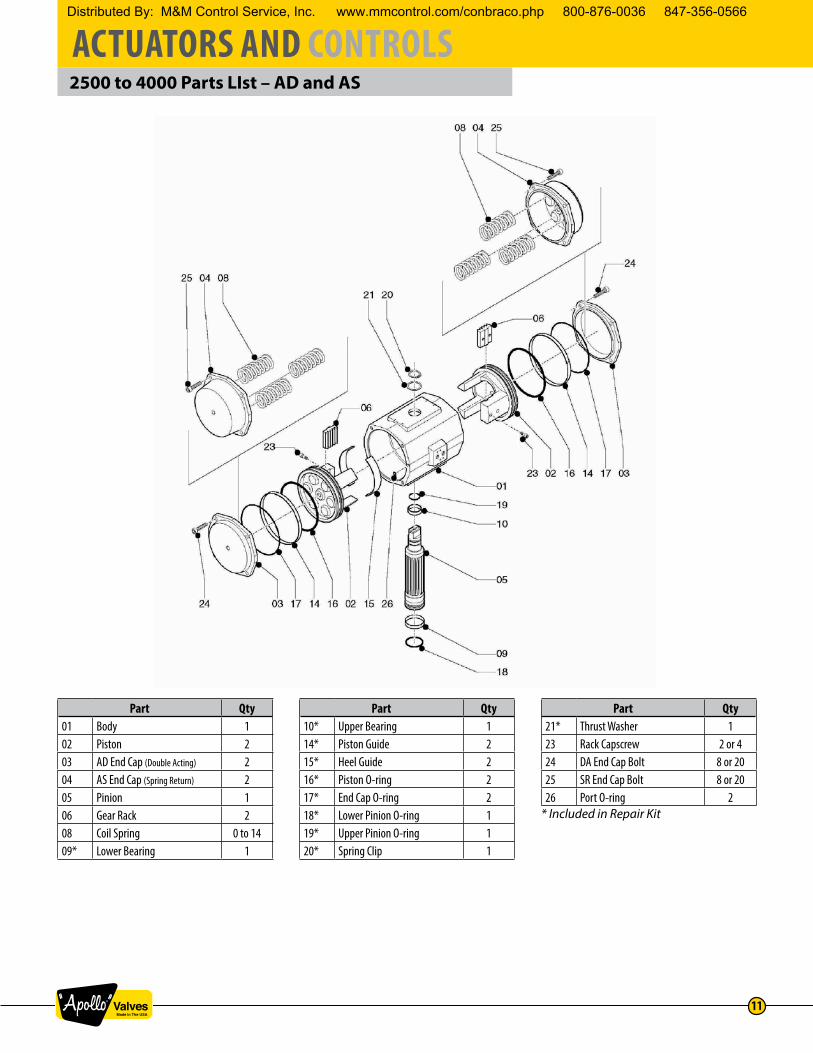
2500 to 4000 Parts LIst – AD and AS
Part Qty01 Body 102 Piston 203 AD End Cap (Double Acting) 204 AS End Cap (Spring Return) 205 Pinion 106 Gear Rack 208 Coil Spring 0 to 1409* Lower Bearing 1
Part Qty10* Upper Bearing 114* Piston Guide 215* Heel Guide 216* Piston O-ring 217* End Cap O-ring 218* Lower Pinion O-ring 119* Upper Pinion O-ring 120* Spring Clip 1
Part Qty21* Thrust Washer 123 Rack Capscrew 2 or 424 DA End Cap Bolt 8 or 2025 SR End Cap Bolt 8 or 2026 Port O-ring 2
* Included in Repair Kit
Distributed By: M&M Control Service, Inc. www.mmcontrol.com/conbraco.php 800-876-0036 847-356-0566

ACTUATORS AND CONTROLS
12
Dimensional Data – AD and AS (Sizes 0600 to 4000)
RACK & PINION ACTUATOR ENVELOPE DIMENSIONS – INCHES
ModelOverall Length A (DA)
Overall LengthB (SR)
BodyHeight
C
BodyWidth
H
SolenoidPad Offset
I
PortLocation
J
AdjustableClosed Stop
J1*
AdjustableClosed Stop
L*
StopSizeY*
StopProtrusion
X max.*0600 15.24 18.78 8.66 8.15 4.45 3.33 3.50 1.63 5/8”-11 4.510950 16.69 20.35 10.20 9.09 4.96 4.15 4.03 1.63 5/8”-11 4.511600 20.31 25.08 11.69 10.43 5.59 4.74 4.50 1.87 3/4”-10 4.882500 14.88 22.40 14.02 13.78 7.28 7.01 N/A N/A N/A N/A4000 19.76 32.83 14.96 14.96 7.87 7.48 N/A N/A N/A N/A
*Applies to double stop versions only
0600 - 1600
0600 - 0950
1600
2500, 4000
2500
4000
For Models with Dual Adjustable Limit Stops
Distributed By: M&M Control Service, Inc. www.mmcontrol.com/conbraco.php 800-876-0036 847-356-0566
ACTUATORS AND CONTROLS
13
Dimensional Data – AD and AS (Sizes 0600 to 4000)
RACK & PINION ACTUATOR DRIVE DETAILS – INCHES
ModelBottomPinion
DiameterK
ValveStem
ClearanceM1
Insert orAdapterHeight
M3
PinionRecess
N
StandardSquareOutputO max
StandardSquareOutputO min
AcrossCorners
DiameterP1
0600 2.68 2.05 1.16 0.06 1.068 1.063 1.4250950 2.95 2.52 1.95 0.06 1.424 1.417 1.8981600 3.74 3.23 2.30 0.06 1.817 1.811 2.3702500 3.35 2.60 N/A 0.12 1.817 1.811 2.3704000 4.72 3.03 N/A 0.06 2.173 2.165 2.843
RACK & PINION ACTUATOR MOUNTING DIMENSIONS – INCHES
ModelPrimaryISO “F”
Pattern
PrimaryBolt
Circle V
PrimaryFastener
W
SecondaryISO “F”
Pattern
SecondaryBolt Circle
V1
SecondaryFastener
W10600 F10 4.016 3/8”-16 x .63” F12 4.921 1/2”-13 x .79”0950 F10 4.016 3/8”-16 x .63” F14 5.512 5/8”-11 x .98”1600 F16 6.496 3/4”-10 x 1.14” N/A N/A N/A2500 F16 6.496 3/4”-10 x 1.14” N/A N/A N/A4000 F16 6.496 3/4”-10 x 1.14” F25 10.000 5/8”-11 x .98”
RACK & PINION ACTUATOR MOUNTING DETAILS – INCHES
ModelNamurShaft
ExtensionD
NamurShaft
DiameterE
ThrustBearing
DiameterE2
Namur ShaftFlats
F
NamurFlat
LengthG
Namur Bolt
PatternT1
Namur Bolt
PatternU1
0600 1.18 2.17 2.56 1.42 0.39 5.118 1.1810950 1.18 2.17 2.56 1.42 0.39 5.118 1.1811600 1.18 2.52 2.95 1.42 039 5.118 1.1812500 1.18 2.17 2.56 1.42 0.39 5.118 1.1814000 1.18 2.52 3.15 1.42 0.39 5.118 1.181
Distributed By: M&M Control Service, Inc. www.mmcontrol.com/conbraco.php 800-876-0036 847-356-0566
ACTUATORS AND CONTROLS
14
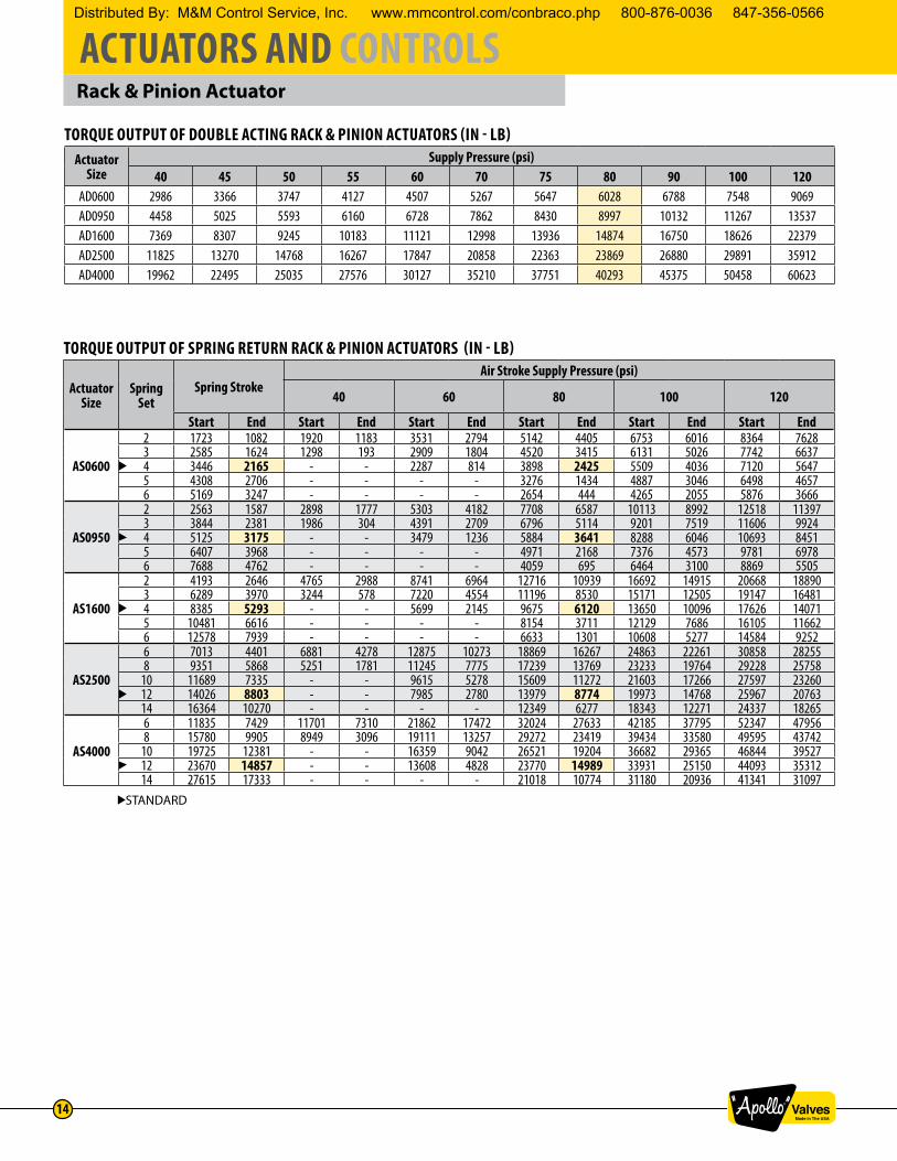
Rack & Pinion Actuator
TORQUE OUTPUT OF DOUBLE ACTING RACK & PINION ACTUATORS (IN - LB)Actuator
SizeSupply Pressure (psi)
40 45 50 55 60 70 75 80 90 100 120AD0600 2986 3366 3747 4127 4507 5267 5647 6028 6788 7548 9069AD0950 4458 5025 5593 6160 6728 7862 8430 8997 10132 11267 13537AD1600 7369 8307 9245 10183 11121 12998 13936 14874 16750 18626 22379AD2500 11825 13270 14768 16267 17847 20858 22363 23869 26880 29891 35912AD4000 19962 22495 25035 27576 30127 35210 37751 40293 45375 50458 60623
TORQUE OUTPUT OF SPRING RETURN RACK & PINION ACTUATORS (IN - LB)
Actuator Size
Spring Set
Spring StrokeAir Stroke Supply Pressure (psi)
40 60 80 100 120
Start End Start End Start End Start End Start End Start End
AS0600
2 1723 1082 1920 1183 3531 2794 5142 4405 6753 6016 8364 76283 2585 1624 1298 193 2909 1804 4520 3415 6131 5026 7742 66374 3446 2165 - - 2287 814 3898 2425 5509 4036 7120 56475 4308 2706 - - - - 3276 1434 4887 3046 6498 46576 5169 3247 - - - - 2654 444 4265 2055 5876 3666
AS0950
2 2563 1587 2898 1777 5303 4182 7708 6587 10113 8992 12518 113973 3844 2381 1986 304 4391 2709 6796 5114 9201 7519 11606 99244 5125 3175 - - 3479 1236 5884 3641 8288 6046 10693 84515 6407 3968 - - - - 4971 2168 7376 4573 9781 69786 7688 4762 - - - - 4059 695 6464 3100 8869 5505
AS1600
2 4193 2646 4765 2988 8741 6964 12716 10939 16692 14915 20668 188903 6289 3970 3244 578 7220 4554 11196 8530 15171 12505 19147 164814 8385 5293 - - 5699 2145 9675 6120 13650 10096 17626 140715 10481 6616 - - - - 8154 3711 12129 7686 16105 116626 12578 7939 - - - - 6633 1301 10608 5277 14584 9252
AS2500
6 7013 4401 6881 4278 12875 10273 18869 16267 24863 22261 30858 282558 9351 5868 5251 1781 11245 7775 17239 13769 23233 19764 29228 25758
10 11689 7335 - - 9615 5278 15609 11272 21603 17266 27597 2326012 14026 8803 - - 7985 2780 13979 8774 19973 14768 25967 2076314 16364 10270 - - - - 12349 6277 18343 12271 24337 18265
AS4000
6 11835 7429 11701 7310 21862 17472 32024 27633 42185 37795 52347 479568 15780 9905 8949 3096 19111 13257 29272 23419 39434 33580 49595 43742
10 19725 12381 - - 16359 9042 26521 19204 36682 29365 46844 3952712 23670 14857 - - 13608 4828 23770 14989 33931 25150 44093 3531214 27615 17333 - - - - 21018 10774 31180 20936 41341 31097
STANDARD
Distributed By: M&M Control Service, Inc. www.mmcontrol.com/conbraco.php 800-876-0036 847-356-0566
ACTUATORS AND CONTROLS
15
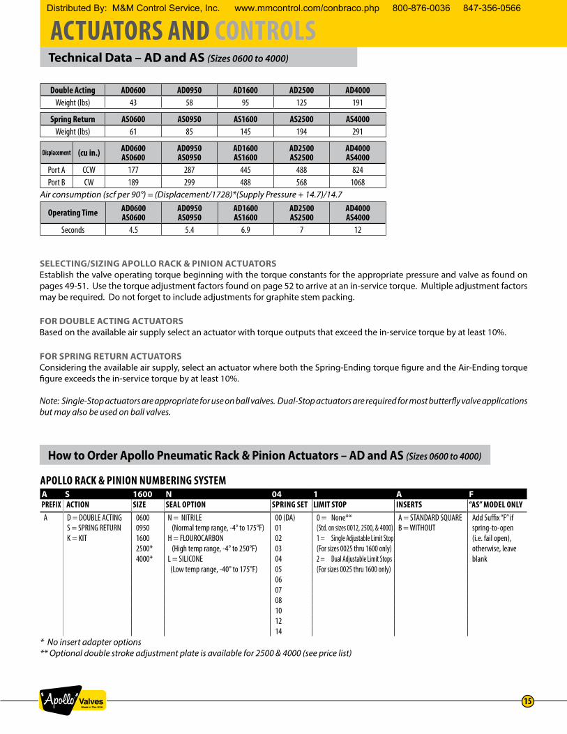
Technical Data – AD and AS (Sizes 0600 to 4000)
How to Order Apollo Pneumatic Rack & Pinion Actuators – AD and AS (Sizes 0600 to 4000)
SELECTING/SIZING APOLLO RACK & PINION ACTUATORSEstablish the valve operating torque beginning with the torque constants for the appropriate pressure and valve as found on pages 49-51. Use the torque adjustment factors found on page 52 to arrive at an in-service torque. Multiple adjustment factors may be required. Do not forget to include adjustments for graphite stem packing.
FOR DOUBLE ACTING ACTUATORSBased on the available air supply select an actuator with torque outputs that exceed the in-service torque by at least 10%.
FOR SPRING RETURN ACTUATORSConsidering the available air supply, select an actuator where both the Spring-Ending torque figure and the Air-Ending torque figure exceeds the in-service torque by at least 10%.
Note: Single-Stop actuators are appropriate for use on ball valves. Dual-Stop actuators are required for most butterfly valve applications but may also be used on ball valves.
Double Acting AD0600 AD0950 AD1600 AD2500 AD4000Weight (lbs) 43 58 95 125 191
Spring Return AS0600 AS0950 AS1600 AS2500 AS4000Weight (lbs) 61 85 145 194 291
Displacement (cu in.) AD0600AS0600
AD0950AS0950
AD1600AS1600
AD2500AS2500
AD4000AS4000
Port A CCW 177 287 445 488 824Port B CW 189 299 488 568 1068
Air consumption (scf per 90°) = (Displacement/1728)*(Supply Pressure + 14.7)/14.7
Operating Time AD0600AS0600
AD0950AS0950
AD1600AS1600
AD2500AS2500
AD4000AS4000
Seconds 4.5 5.4 6.9 7 12
APOLLO RACK & PINION NUMBERING SYSTEMA S 1600 N 04 1 A FPREFIX ACTION SIZE SEAL OPTION SPRING SET LIMIT STOP INSERTS “AS” MODEL ONLYA D = DOUBLE ACTING 0600 N = NITRILE 00 (DA) 0 = None** A = STANDARD SQUARE Add Suffix “F” if
S = SPRING RETURN 0950 (Normal temp range, -4° to 175°F) 01 (Std. on sizes 0012, 2500, & 4000) B = WITHOUT spring-to-openK = KIT 1600 H = FLOUROCARBON 02 1 = Single Adjustable Limit Stop (i.e. fail open),
2500* (High temp range, -4° to 250°F) 03 (For sizes 0025 thru 1600 only) otherwise, leave 4000* L = SILICONE 04 2 = Dual Adjustable Limit Stops blank
(Low temp range, -40° to 175°F) 05 (For sizes 0025 thru 1600 only)060708101214
* No insert adapter options** Optional double stroke adjustment plate is available for 2500 & 4000 (see price list)
Distributed By: M&M Control Service, Inc. www.mmcontrol.com/conbraco.php 800-876-0036 847-356-0566

ACTUATORS AND CONTROLS
16
Acuator Inserts – AD and AS (Sizes 0025 to 1600)
X-Dimension Y-Dimension X-Dimension Y-Dimension
CX04573 ADAPTER, 11MM SQ 0.433 0.433 11 11CX04549 ADAPTER,0.500DIA X 0.397FLAT, 0.394 Ø0.500 10 Ø13CX04684 ADAPTER,BLANKCX04620 ADAPTER, 77D104 TO AD/AS 0040,0065; 7MM SQ. 0.28 0.28 7 7CX04550 ADAPTER,0.555DIA X 0.397FLAT, 0.394 Ø0.55 10 Ø14CX04570 ADAPTER,11MM SQ,ALUM,77D105 TO 0.433 0.433 11 11CX04551 ADAPTER,0.625DIA X 0.476FLAT, 0.476 Ø0.627 12 Ø16CX04580 ADAPTER,14MM SQ, 0.551 0.55 14 14CX04552 ADAPTER,0.751DIA X 0.555FLAT, 0.551 Ø0.748 14 Ø19CX04675 ADAPTER,BLANKCX04553 ADAPTER,0.397DIA X 0.524FLAT, 0.394 0.524 10 Ø13CX04554 ADAPTER,0.625DIA X 0.475FLAT, 0.476 Ø0.627 12 Ø16CX04623 ADAPTER, 14MM SQ 0.551 0.55 14 14CX04555 ADAPTER,0.750DIA X 0.555FLAT, 0.551 Ø0.748 14 Ø19CX04584 ADAPTER, 17MM SQ 0.669 0.669 17 17CX04569 ADAPTER,19MM (0.748 SQ,) 0.748 0.748 19 19CX04685 ADAPTER,BLANKCX04556 ADAPTER,0.628DIA X 0.376FLAT, 0.375 Ø.628 9.5 Ø16CX04720 ADAPTER, 11MM SQ 0.433 0.433 11 11CX04558 ADAPTER,0.475DIA X 0.650RECT, 0.475 0.65 12 17CX04572 ADAPTER, 77D107-108 TO 0.551 0.551 14 14CX04566 ADAPTER,0.750DIA X 0.555FLAT, 0.551 Ø0.748 14 Ø19CX04560 ADAPTER,0.673 X 0.886RECT, 0.669 0.875 17 22CX04571 ADAPTER,19MM 0.748 0.748 19 19CX04581 ADAPTER,22MM 0.87 0.87 22 22CX04559 ADAPTER,0.869DIA X 1.18RECT, 0.87 1.18 22 30CX04557 ADAPTER,1.250DIA X 0.949FLAT, 0.95 Ø1.25 24 Ø32CX04582 ADAPTER,27MM 1.063 1.063 27 27CX04686 ADAPTER,BLANKCX04567 ADAPTER,0.673 X 0.886RECT, 0.669 0.886 17 22.5CX04562 ADAPTER,1.125DIA X 0.870FLAT, 0.87 Ø1.127 22 Ø29CX04561 ADAPTER,1.250DIA X 0.949FLAT, 0.95 Ø1.25 24 Ø32CX04622 ADAPTER, 36MM SQ 1.417 1.417 36 36CX04563 ADAPTER,BLANKCX04568 ADAPTER,1.250DIA X 0.870FLAT, 0.87 Ø1.127 22 Ø29CX04564 ADAPTER,1.248DIA X 0.950FLAT, 0.95 Ø1.25 24 Ø32CX04565 ADAPTER,BLANK
CX04680 CLASS 150/300 2"HPBFV (.356 x .490) 0.354 0.49 9 12.5CX04714 CLASS 150/300 2-1/2" & 3" HPBFV (.434 x .580) 0.433 0.55 11 14
AD/AS 0150/0200/0350/0600 CX04681 CLASS 150/300 4"HPBFV (.553 x .725) 0.551 0.725 14 18(Fits HPBFVs) CX04682 CLASS 150/300 5"&6" HPBFV (.671 x .890) 0.669 0.886 17 22.5
CX04683 CLASS 150 8" HPBFV (.750 x .1.01) 0.748 1.01 19 25.5
Actuator Item Number Description
Actutator Inserts
AD/AS 0025
AD/AS 0040/0065
AD/AS 0100
AD/AS 0150/0200/0350/0600
AD/AS 0950
AD/AS 1600
Fits Stems of the Following DimensionsImperial (in) Metric (mm)
Notes:
1. Inserts for op0onal stem sizes or when the actuator is ordered without a factory installed insert. 2. Contact factory for addi0onal configura0ons and pricing.
Insert-‐Stem Dimensions
Distributed By: M&M Control Service, Inc. www.mmcontrol.com/conbraco.php 800-876-0036 847-356-0566

ACTUATORS AND CONTROLS
17
“Acutorque” Stainless Steel ActuatorDESIGN AND CONSTRUCTION
1. INVESTMENT CAST BODY Assures manufacturing of other special alloys, such as Monel
2. UNIQUE DRIVE PINION One piece stainless steel alloy shaft, precision machined gear and teeth for precise control
3. BEARINGS Replaceable top and bottom TFE Pinion Bearings to ensure low friction, stability above 400°F, and chemical resistance
4. TRAVEL STOPS Provides +/-4° travel adjustment in outboard direction
5. ACCESSORY MOUNTING Manufactured to NAMUR to provide international standardized mounting
6. STAINLESS STEEL PISTONS Precision cast pistons are guided through full face engagement with the pinion and piston guide
7. NAMUR SLOTTED SHAFT Standard to provide a self-centering positive drive for positioners, a variety of switches
8. ACTUATOR MOUNTING Manufactured in accordance with ISO 5211 to ensure mounting the actuator directly on valves
9. PRE-LOADED CARTRIDGES Converts a standard double acting actuator to a spring return unit by simply removing the end caps and adding the spring cartridges
10. NAMUR SOLENOID MOUNTING International standard for direct mounting of solenoid valves
14
6
10
7
3b
3a
2
9
5
Distributed By: M&M Control Service, Inc. www.mmcontrol.com/conbraco.php 800-876-0036 847-356-0566

ACTUATORS AND CONTROLS
18
Operation – “Acutorque” Stainless Steel Actuator
The Apollo® Acutorque actuator is manufactured with an integral and internal air manifold. The solenoid mounting pad is manufactured to Namur dimensional standards as to allow for the direct mounting of various manufacturers’ solenoid valves and other flow control devices. For applications not requiring a direct mount solenoid valve, ports are tapped to NPT standards (American National Standard taper threads).
REVERSE ROTATIONWhen required, a clockwise rotation of the drive pinion, by means of air to PORT A can be achieved by reversing the pistons inside the actuator body (rotate 180 degrees).
SPRING CONFIGURATIONEach Acutorque actuator comes with a complete spring pack (6 springs per side with nylon retainers) unless otherwise specified. When less than the full spring pack is desired for various torque outputs (see torque chart); springs can be removed from the actuator end caps. It is very important that springs can be arranged in a symmetrical manner (positioned as shown) so that unwarranted side-load does not occur between the pistons and actuator body. CAUTION: Refer to operation and maintenance instructions before disassembly and removal of springs.
Air to PORT A: Pressure applied enters center of chamber forcing the pistons outward and rotating the drive pinion in a counter-clockwise direction and forcing exhaust air out of PORT B.
Air to PORT B: Air pressure enters the outer chambers forcing the pistons inward and rotating the drive pinion in a clockwise direction while forcing exhaust air out of PORT A.
Loss of air pressure in the center chamber allows energy in the compressed springs to force the pistons inward, resulting in a clockwise rotation of the drive pinion while exhaust air leaves via PORT A.
Distributed By: M&M Control Service, Inc. www.mmcontrol.com/conbraco.php 800-876-0036 847-356-0566

ACTUATORS AND CONTROLS
19
Features – “Acutorque” Stainless Steel Actuator
CORROSION RESISTANCEAll metal components are cast or machined from Stainless Steel or Monel, which offers excellent resistance to most corrosive chemicals as well as industrial atmospheres.NO LUBRICATIONAll actuators are factory lubricated for the optimum life of the actuator under normal conditions. Teflon® piston bearings are used because of their self-lubricating properties.SIMPLE MAINTENANCEEach actuator is designed for ease of maintenance. Should you wish to change a spring rating or completely rebuild a unit, total disassembly and reassembly is easily performed in just minutes with standard shop tools.ISO/NAMUR MOUNTINGBy using ISO/Namur standards, our actuators lend themselves to a host of various manufacturers’ direct mount accessories. Solenoid valves, limit switches, positioners, etc. bolt directly to the actuator and in turn reduces the cost of assembly and installation of automated packages. Flexibility for future system modifications is greatly enhanced.QUALITYEach part of the actuator must pass a stringent quality test before it can be incorporated into an assembly. All materials used in construction must be certified and tested to prove their proper composition. Every cast part must pass an X-ray test before proceeding to the machining process. After machining, every part is dimensionally evaluated to assure it meets acceptable tolerance.SAFETYAll actuator bodies and end caps are investment cast stainless steel, rugged and built to last. It may be argued that the mechanical properties of stainless steel permit the ability to use this wall tubing in the construction of an actuator. However, that is not the case with our actuator. Thick wall castings mean protection for actuator internal porting and components as well as maintenance and operating personnel. Our unique drive pinion design ensures blowout proof protection. Spring retainers are incorporated to allow safe removal of end caps during spring torque rating change or rebuild process.
GRADE OF STAINLESS STEELBody & End Caps 304Shaft 17-4 phPiston 303Bolts 18-8
Part Qty Material1 Body 1 304 Stainless Steel2 Piston 2 303 Stainless Steel3 End Caps-Double Acting 2 Stainless Steel4 Drive Pinion 1 17-4 Stainless Steel5 Guide Bearing Plate 2 Nylon 66 Pinion Bearing Top 1 Teflon7 Pinion Bearing Bottom 1 Teflon8 Snap Ring 1 Stainless Steel9 O-Ring-Inner Top 1 Viton
10 O-Ring-Outer Top 1 Viton11a Washer 1 Stainless Steel11b Bearing 1 Nylon 612 O-Ring-Inner Bottom 1 Viton13 O-Ringer-Outer Bottom 1 Viton14 O-Ring-Piston 2 Viton15 Bearing-Piston 2 Nylon 6
Part Qty Material16 O-Ring-End Cap 2 Nitrile
17a Bolts-End Cap 8 Stainless Steel17b Spring Bearing 8 Stainless Steel18 Adjusting Travel Stop 2 Stainless Steel19 O-Ring-Travel Stop 2 Nitrile
20a Washer 2 Stainless Steel20b Nut-Travel Stop 2 Stainless Steel21 End Nut-Travel 2 Stainless Steel22 Spring Retainer (S) * Nylon 623 Spring Retainer (L) * Nylon 624 Spring * Plated CS25 Spring Screw * Stainless Steel26 Spring Nut * Stainless Steel27 Positioner Indicator 1 Nylon28 Plug 2 Nylon 6
Distributed By: M&M Control Service, Inc. www.mmcontrol.com/conbraco.php 800-876-0036 847-356-0566

ACTUATORS AND CONTROLS
20
Dimensional Data – “Acutorque” Stainless Steel Actuator
MOUNTING DIMENSIONSModel R S T V W X Y Z AA BB CC DD EE FF GG HH
3SD04500 mm 24 1/4”NPT M5 11 15 M5 8 42 M5 6 30 80 88.9 31.75 M5 83SS04560 in 0.95 1/4”NPT M5 0.4 0.59 M5 0.31 1.65 M5 0.24 1.18 3.15 3.5 1.25 M5 0.313SD06000 mm 24 1/4”NPT M5 14 15 M6 8 50 M5 6 30 80 88.9 31.75 M6 83SS06060 in 0.95 1/4”NPT M5 0.55 0.59 M6 0.31 1.97 M5 0.24 1.18 3.15 3.5 1.25 M6 0.313SD08500 mm 24 1/4”NPT M5 19 17 M8 12 70 M5 6 30 80 114 38 M8 123SS08560 in 0.95 1/4”NPT M5 0.75 0.68 M8 0.47 2.75 M5 0.24 1.18 3.15 4.5 1.5 M8 0.473SD10500 mm 24 1/4”NPT M5 19 20 M8 12 70 M5 6 30 80 114 38 M8 123SS10560 in 0.95 1/4”NPT M5 0.75 0.79 M8 0.47 2.75 M5 0.24 1.18 3.15 4.5 1.5 M8 0.473SD12500 mm 24 1/4”NPT M5 22 30 M8 18 102 M5 8 30 130
NA50.8
NA NA3SS12560 in 0.95 1/4”NPT M5 0.87 1.2 M8 0.71 4.02 M5 0.31 1.18 5.12 23SD14000 mm 24 1/4”NPT M5 22 27 M10 18 102 M5 8 30 130
NA 50.8
NA NA3SS14060 in 0.95 1/4”NPT M5 0.87 1.06 M10 0.71 4.02 M5 0.31 1.18 5.12 23SD17000 mm 24 1/4”NPT M5 32 36 M12 24 125 M5 8 30 130
NA76
NA NA 3SS17060 in 0.95 1/4”NPT M5 1.26 1.42 M12 0.95 4.92 M5 0.31 1.18 5.12 33SD21000 mm 24 1/4”NPT M5 36 43 M20 28 140 M5 8 30 130
NA76
NA NA3SS21060 in 0.95 1/4”NPT M5 1.42 1.69 M20 1.1 5.51 M5 0.31 1.18 5.12 3
can we get new drawings from engineering?
TOP BOTTOM
Distributed By: M&M Control Service, Inc. www.mmcontrol.com/conbraco.php 800-876-0036 847-356-0566

ACTUATORS AND CONTROLS
21
Envelope Dimensions – “Acutorque” Stainless Steel Actuator
Double Acting Torque – “Acutorque” Stainless Steel Actuator
Technical Data – “Acutorque” Stainless Steel Actuator
DIMENSIONSModel AS C D E F G H J K L N M Q
3SD04500 mm 168 65 52.5 62.5 35 16 4 20 10 12 16 23 323SS04560 in 6.61 2.56 2.07 2.46 1.38 0.63 0.16 0.79 0.39 0.47 0.63 0.91 1.263SD06000 mm 180 81 60.5 74 39 16 4 20 10 12 16 23 323SS06060 in 7.09 3.19 2.38 2.91 1.54 0.63 0.16 0.79 0.39 0.47 0.63 0.91 1.263SD08500 mm 222 108 74 100.5 52 16 4 20 10 12 16 24 323SS08560 in 8.74 4.25 2.91 3.96 2.05 0.63 0.16 0.79 0.39 0.47 0.63 0.95 1.263SD10500 mm 290 133 86.5 117 58.5 16 4 20 10 12 16 30 323SS10560 in 11.42 5.24 3.41 4.61 2.3 0.63 0.16 0.79 0.39 0.47 0.63 1.18 1.263SD12500 mm 390 155 110.2 136 68 20 4 30.5 10.5 12 16 40 323SS12560 in 15.5 5.02 3.59 5.65 2.91 0.79 0.16 1.2 0.41 0.47 0.63 1.57 1.263SD14000 mm 420 176 116.5 156 79 20 4 30.5 10.5 12 16 40 323SS14060 in 16.54 6.93 4.59 6.14 3.11 0.79 0.16 1.2 0.41 0.47 0.63 1.57 1.263SD17000 mm 538 210 131.5 193 98 20 4 30.5 10.5 12 16 50 323SS17060 in 21.18 8.27 5.18 7.6 3.86 0.79 0.16 1.2 0.41 0.47 0.63 1.97 1.263SD21000 mm 698 258 156 236 120 32 4 30.5 10.5 12 16 68 323SS21060 in 27.48 10.16 6.14 9.29 4.72 1.26 0.16 1.2 0.41 0.47 0.63 2.68 1.26
Actuator Model
Torque (Inch/Lbs) vs. Air Supply Pressure (PSI)40 60 80 100 120 150
3SD04500 74 116 152 199 239 2893SD06000 151 234 328 413 499 6003SD08500 365 548 732 915 1097 13153SD10500 701 1068 1436 1829 2184 2632
Actuator Model
Torque (Inch/Lbs) vs. Air Supply Pressure (PSI)40 60 80 100 120 150
3SD12500 1355 2069 2759 3449 4115 51683SD14000 2018 3032 4039 5046 6056 66153SD17000 2868 4050 5324 6640 7987 100423SD21000 5328 8462 11188 13884 16709 20929
AcuatorModel
Volume (in³ per90° cycle)
Air Consumption (scf per 90° rotation)*CW CCW
3SS045X0 45 8.5 6.53SS060X0 60 17.5 14.83SS085X0 85 36.5 24.53SS105X0 105 72 49.33SS125X0 125 196 1473SS140X0 140 358 2783SS170X0 170 542 3823SS210X0 210 753 470
Notes: *Temperature and atmospheric conditions could change values above.
Acuator Model Weight (lbs)3SS045X0 93SS060X0 163SS085X0 233SS105X0 373SS125X0 523SS140X0 753SS170X0 1883SS210X0 258
Distributed By: M&M Control Service, Inc. www.mmcontrol.com/conbraco.php 800-876-0036 847-356-0566

ACTUATORS AND CONTROLS
22
Spring Return Torque – “Acutorque” Stainless Steel Actuator
Actuator Model
Spring Set#*
Spring StrokeTorque (Inch/Lbs) vs. Air Supply Pressure (PSI)
40 60 80 100 120 150
0 90 0 90 0 90 0 90 0 90 0 90 0 90
3SS045X0
2 34 21 56 43 98 84 136 121 178 162 220 203 256 2303 49 29 45 24 88 65 126 93 165 142 204 179 238 2044 71 43 72 42 115 90 154 126 196 163 218 1755 88 52 109 76 147 109 182 184 209 1566 107 64 97 58 135 91 172 103 190 129
3SS060X0
2 61 37 101 79 167 140 237 214 304 278 369 345 435 3993 93 55 84 48 147 107 219 185 284 248 352 315 405 3504 124 75 129 77 203 157 268 219 331 276 380 3155 156 93 110 45 187 131 250 189 315 250 359 2726 186 112 171 102 233 158 296 218 335 228
3SS085X0
2 172 93 275 206 450 369 645 572 821 744 999 919 1175 10653 257 139 236 126 403 281 602 493 773 661 949 884 1105 9454 343 185 354 192 558 414 729 574 901 743 1042 8255 428 232 516 303 683 490 853 651 975 7056 515 288 473 258 636 405 800 564 915 580
3SS105X0
2 325 182 527 394 852 7033 483 256 443 246 759 537 1137 9394 643 358 665 369 1051 790 1374 1099 1703 1413 1975 15705 805 447 556 119 974 641 1291 934 1615 1241 1852 13406 964 537 888 493 1195 777 1519 1077 1705 1100
3SS125X0
2 628 343 1025 730 1724 14353 945 510 860 425 1545 1118 2310 18644 1259 687 1370 806 2068 1480 2720 2158 3333 2450 4166 30625 1579 865 1199 483 1875 1160 2545 1835 3157 2185 3947 27286 1895 1040 1690 850 2371 1528 2915 1846 3628 2310
3SS140X0
2 905 520 1478 1092 2469 20883 1355 780 1215 642 2210 1639 3195 26204 1808 1035 1956 1197 2935 2180 3960 3175 5000 4000 6250 50105 2257 1301 1692 739 2680 1750 3700 2748 4608 3425 5760 42906 2708 1562 2441 1279 3444 2290 4280 2852 5362 3568
3SS170X0
2 1227 738 1985 1494 3411 29233 1830 1092 1824 1087 3045 2347 3945 36264 2417 1446 2695 1713 4012 3035 4307 4291 6305 5221 7890 65265 3044 1811 2329 1104 3647 2417 4934 3700 6000 4608 7495 57606 3653 2166 3295 1817 4579 3093 5719 3750 7149 4680
3SS210X0
2 2425 1388 4080 2988 7149 61123 3640 2080 3388 1831 6456 4899 9205 76264 4857 2769 5750 3675 8510 6438 11150 9082 9231 12900 16100 128355 6060 3465 5070 2475 7772 5224 10400 5160 7835 12000 15000 110306 7270 4165 7125 4010 9700 4238 6616 10909 13650 9150
* X in Actuator Model is Spring Set
Distributed By: M&M Control Service, Inc. www.mmcontrol.com/conbraco.php 800-876-0036 847-356-0566

ACTUATORS AND CONTROLS
23
Scotch-Yoke ActuatorG SERIES
NAMURThe shaft driven accessory interface conforms to the NAMUR standard and is identical on all G-Series actuators, allowing for standardization of accessory mounting hardware and installation practices • Pneumatic and hydraulic scotch-yoke actuators • Automates ball, butterfly, plug valves and any other 90° rotating mechanisms • Salt Spray Testing per ASTM B117 criteria. Construction features prevent water ingress, allowing G-Series actuators to meet IP 66 and IP 67M specifications and severe high pressure water deluge test
OPERATING RANGESG-Series double acting actuators produce guaranteed minimum torque outputs from 10,000 lb-in. up to 6,000,000 lb-in. The spring return units produce spring torques from 2,500 lb-in. to 3,000,000 lb-in. • Standard operating pressures: Pneumatic — to 200 psig (14 BAR) • Standard operating temperature is -20°F to +200°F (-29°C to +93°C) Optional trims available: 0°F to +350°F (-18°C to +177°C) -50°F to +180°F (-46°C to +82°C) • Mechanical and hydraulic manual overrides are available • MSS and ISO Valve Mounting The G-Series valve interface meets the dimensional requirements of MSS SP-101 or ISO 5211 defined for each torque range
DOUBLE ACTING G1 PNEUMATIC ACTUATOR TORQUE CHART
ApolloModel No.
ReferenceNumber
Stroke Position
Operating Pressure (psig)
40 50 60 70 80 90 100 110 120 150 175 200
Output Torque (In-Lbs)
3TG100800 G01008Start/End 12465 14543 16620 18698 20775 22853 24930 31163 36356 41550Minimum 6579 7675 8772 9868 10965 12061 13158 16447 19188 21929
3TG100900 G01009Start/End 10593 13241 15890 18538 21186 23835 26483 29131 31779 39724Minimum 5591 6989 8386 9784 11182 12579 13977 15375 16772 20966
3TG101000 G01010Start/End 14046 17557 21069 24580 28092 31603 35115 38626Minimum 7413 9266 11120 1973 14826 16680 18533 20386
3TG101200 G01012Start/End 20133 25166 30199 35232Minimum 10626 13282 15938 18595
3TG101400 G01014Start/End 24482 30603 36723Minimum 12921 16152 19382
Distributed By: M&M Control Service, Inc. www.mmcontrol.com/conbraco.php 800-876-0036 847-356-0566

ACTUATORS AND CONTROLS
24
Torque Ratings G Series – Scotch-Yoke Actuator
G SERIES PNEUMATIC DOUBLE-ACTING ACTUATOR TORQUE CHART
ApolloModel No.
Reference Number
Stroke Position
Operating Pressure (psig)40 50 60 70 80 90 100 110 120 150 175 200
Output Torque (In-Lbs)
3TG200900 G2009 Start/End 22441 25647 28852 32058 35264 38470 48087 56102Minimum 11844 13536 15228 16920 18612 20304 25379 29609
3TG201000 G2010 Start/End 21254 25504 29755 34006 38257 42507 46758 51009Minimum 11217 13461 15704 17948 20191 22434 24678 26921
3TG201200 G2012 Start/End 24371 30464 36556 42649 48742 54835 60927Minimum 12862 16078 19294 22509 25725 28941 32156
3TG201400 G2014 Start/End 29636 37046 44455 51864 59273Minimum 15641 19552 23462 27373 31283
3TG201600 G2016 Start/End 39118 48897 58677Minimum 20646 25807 30968
3TG301000 G3010 Start/End 35888 41015 46142 51269 56396 61523 76903 89721 102538Minimum 18941 21647 24353 27059 29764 32470 40588 47352 54117
3TG301200 G3012 Start/End 36847 44216 51585 58955 66324 73693 81063 88432Minimum 19447 23336 27226 31115 35004 38894 42783 46672
3TG301400 G3014 Start/End 35887 44859 53831 62803 71775 80747 89719 98690Minimum 18941 23676 28411 33146 37881 42616 47351 52087
3TG301600 G3016 Start/End 47430 59288 71145 83003 94860Minimum 25033 31291 37549 43807 50065
3TG302000 G3020 Start/End 75266 94082Minimum 39724 49654
All published torques are guaranteed minimum values.
SPRING RETURN G1 PNEUMATIC ACTUATOR TORQUE CHART
ApolloModel No.
Reference Number
Spring Torque (In-Lbs)
Start/Min/End
Operating Pressure (psig)40 50 60 70 80 90 100 110 120 150 175 200
Output Torque Start/Min/End (In-Lbs)
3TG100804 G01008-SR411614 5551 7628 9706 11783 13861 20093 25287 304815708 2439 3543 4648 5752 6849 10138 12880 15621
10015 3783 5861 7938 10016 12093 18326 23520 28713
3TG100904 G01009-SR411614 4820 7469 10117 12765 15414 18062 20710 286555708 2051 3459 4866 6271 7669 9066 10464 14657
10015 3053 5701 8350 10998 13646 16295 18943 26888
3TG101004 G1010-SR411614 6488 10000 13511 17023 20534 24046 275575708 2938 4804 6664 8518 10371 12224 14078
10015 4721 4232 11744 15255 18767 22278 25790
3TG101204 G01012-SR411614 9063 14096 19130 241635708 4306 6973 9630 12286
10015 7296 12329 17362 22395
3TG101404 G01014-SR411614 13413 19534 256545708 6613 9843 13073
10015 11646 17766 23887
3TG100803 G01008-SR313598 6048 8126 10203 12281 18513 23707 289016605 2523 3631 4735 5839 9143 11884 14625
11445 3669 5746 7824 9901 16434 21327 26521
3TG100903 G01009-SR313598 ` 5889 8537 11185 13834 16482 19130 270756605 2437 3850 5257 6665 8071 9469 13662
11445 3509 6157 8806 11454 14102 16751 24695
3TG101003 G01010-SR313598 4908 8420 11931 15443 18954 22466 259776605 1904 3787 5653 7520 9376 11229 13082
11445 2529 6040 9552 13063 16574 20086 23597
3TG101203 G01012-SR313598 7483 12516 17550 225836605 3289 5964 8634 11291
11445 5104 10137 15170 20203
3TG101403 G01014-SR313598 11833 17954 240746605 5601 8848 12078
11445 9453 15574 21695
Distributed By: M&M Control Service, Inc. www.mmcontrol.com/conbraco.php 800-876-0036 847-356-0566

ACTUATORS AND CONTROLS
25
Torque Ratings G Series – Scotch-Yoke Actuator
SPRING RETURN G1 PNEUMATIC ACTUATOR TORQUE CHART (CONT.)
ApolloModel No.
Reference Number
Spring Torque (In-Lbs)
Start/Min/End
Operating Pressure (psig)40 50 60 70 80 90 100 110 120 150 175 200
Output Torque Start/Min/End (In-Lbs)
3TG100802 G01008-SR215526 8443 10521 16753 21947 271417352 3692 4796 8109 10857 13598
13037 5692 7770 14002 19196 24390
3TG100902 G01009-SR215526 6777 9425 12074 14722 17370 253157352 2800 4214 5622 7029 8437 12635
13037 4026 6674 3923 11971 14619 22564
3TG101002 G01010-SR215526 6660 10171 13683 17194 20706 242177352 2736 4611 6477 8348 10202 12055
13037 3909 7420 10932 14443 17955 21466
3TG101202 G01012-SR215526 5723 10756 15789 208237352 2228 4922 7597 10264
13037 2972 8005 13039 18072
3TG101402 G01014-SR215526 10073 16194 223147352 4559 7811 11051
13037 7322 13443 19563
3TG100801 G0108-SR118470 8599 14831 20025 252198749 3364 6703 9463 12223
14776 4516 10748 15942 21136
3TG100901 G0109-SR118470 7503 1152 12800 15448 233938749 2764 4207 5623 7030 11253
14776 3420 6069 8717 11365 19310
3TG101001 G01010-SR118470 8249 11761 15272 18784 222958749 3174 5071 6937 8803 10669
14776 4166 7678 11189 14701 18212
3TG101201 G01012-SR118470 8834 13868 189018749 3492 6190 8865
14776 4752 9785 14818
3TG101401 G01014-SR118470 8151 14272 203928749 3121 6405 9658
14776 4068 10189 16309
Distributed By: M&M Control Service, Inc. www.mmcontrol.com/conbraco.php 800-876-0036 847-356-0566

ACTUATORS AND CONTROLS
26
Torque Ratings G Series – Scotch-Yoke Actuator
SPRING-RETURN ACTUATOR
ApolloModel No.
Reference Number
Spring Torque (In-Lbs)
Start/Min/End
Operating Pressure (psig)40 50 60 70 80 90 100 110 120
Output Torque Start/Min/End (In-Lbs)
3TG200902 G2009-SR226818 14072 12882 596422074 8829
3TG201002 G2010-SR226818 13859 18810 22361 2661112882 5848 8110 10369 1262822074 8616 12866 17117 21368
3TG201202 G2012-SR226818 12159 18252 24344 30437 3653012882 4926 8185 11423 14661 1789622074 6915 13008 19101 25194 31286
3TG201402 G2014-SR226818 12648 20057 27466 3487512882 5191 9145 13082 1702022071 7404 14814 22223 29632
3TG201602 G2016-SR226818 14720 24500 3427912882 6308 11506 1670322074 9477 19256 29036
3TG200901 G2009-SR1309971474225004
3TG201001 G2010-SR130997 14871 19122 2337314742 5957 8249 1050825004 8248 12498 16749
3TG201201 G2012-SR130997 21106 27199 3329114742 9303 12541 1577925004 14482 20575 26668
3TG201401 G2014-SR130997 16819 24228 3163714742 7014 10962 1490025004 10195 17604 25013
3TG201601 G2016-SR130997 21261 3104114742 9386 1458325004 14638 24417
3TG200904 G2009-SR420678 10155 13361 16567 197729903 4185 5900 7603 9307
16917 5998 9204 12410 15616
3TG201004 G2010-SR420678 11058 15308 19559 23810 28061 323119903 4675 6935 9194 11453 13712 15956
16917 6901 11152 15402 19653 23904 28155
3TG201204 G2012-SR420678 11766 17859 23952 30044 36137 422309903 5052 8290 11528 14760 17975 21191
16917 7609 13702 19795 25888 31980 38073
3TG201404 G2014-SR420678 10939 18348 25757 33166 405759903 4610 8550 12488 16407 20318
16917 6782 14191 21600 29009 36419
3TG201604 G2016-SR420678 20420 30200 399799903 9652 14842 20003
16917 16264 26043 35823
3TG200903 G2009-SR324139 13833 1703911457 5833 753919390 8584 11790
3TG201003 G2010-SR324139 12575 16826 21077 25327 2957811457 5150 7426 9685 11944 1420319390 7326 11577 15828 20078 24329
3TG201203 G2012-SR324139 15126 21219 27311 33404 3949711457 6522 9760 12998 16236 1946019390 9877 15970 22062 28155 34248
3TG201403 G2014-SR324139 15615 23024 30433 3784211457 6782 10720 14657 1858719390 10366 17775 25184 32593
All published torques are guaranteed minimum values.
Distributed By: M&M Control Service, Inc. www.mmcontrol.com/conbraco.php 800-876-0036 847-356-0566

ACTUATORS AND CONTROLS
27
Torque Ratings G Series – Scotch-Yoke Actuator
SPRING-RETURN ACTUATOR (CONT.)
ApolloModel No.
Reference Number
Spring Torque (In-Lbs)
Start/Min/End
Operating Pressure (psig)40 50 60 70 80 90 100 110 120
Output Torque Start/Min/End (In-Lbs)
3TG201603 G2016-SR324139 17687 27467 3724611457 7883 13081 1827319390 12438 22218 31997
3TG301002 G3010-SR249017 2065522571 684836975 7346
3TG301202 G3012-SR249017 25456 32826 40195 4756422571 9568 13568 17516 2143336975 12147 19516 26886 34255
3TG301402 G3014-SR249017 21936 30907 39879 48851 5782322571 7591 12527 17349 22117 2688536975 8626 17598 26570 35542 44514
3TG301602 G3016-SR249017 30278 42135 5399322571 12185 18548 2484936975 16968 28826 40683
3TG302002 G3020-SR249017 34398 5321522571 14422 2443636975 21089 39905
3TG301001 G3010-SR1540452530742224
3TG301201 G3012-SR154045 27024 34394 4176325307 10497 14497 1842042224 13960 21329 28698
3TG301401 G3014-SR154045 25106 34078 43050 5202225307 9456 14326 19104 2387342224 12041 21013 29985 38957
3TG301601 G3016-SR154045 24476 36334 4819125307 9107 15535 2183742224 11412 23269 35127
3TG302001 G3020-SR154045 28597 4741325307 11351 2142342224 15532 34349
3TG301004 G3010-SR436568 19695 24822 2994917123 7867 10637 1336128566 10851 15978 21105
3TG301204 G3012-SR436568 20012 27381 34751 42120 49489 5685817123 8038 11996 15913 19830 23746 2766328566 11168 18537 25906 33276 40676 48014
3TG301404 G3014-SR436568 22258 31239 40201 49173 58145 6711717123 9257 14042 18810 23578 28347 3308928566 13414 22385 31357 40329 49301 58273
3TG301604 G3016-SR436568 15857 27714 39572 51429 6328717123 5764 12174 18475 24777 3106828566 7013 18870 30728 42585 54443
3TG301003 G3010-SR342128 20609 2573519573 7746 1052832379 9833 14960
3TG301203 G3012-SR342128 23167 30537 37906 45275 5264519573 9135 13115 17032 20949 2486532379 12392 19761 27130 34500 41869
3TG301403 G3014-SR342128 18044 27016 35988 44960 53931 6290319573 6305 11223 16012 20781 25549 3031732379 7268 15240 25212 34184 43156 52127
3TG301603 G3016-SR342128 23501 35358 47216 5907319573 9315 15678 21980 2828232379 12725 24582 36440 48297
3TG302003 G3020-SR342128 39479 5829519573 17868 2786832379 28703 47519
Distributed By: M&M Control Service, Inc. www.mmcontrol.com/conbraco.php 800-876-0036 847-356-0566

ACTUATORS AND CONTROLS
28
AE Series ActuatorsAE SERIES Ruggedly built and designed for easy installation, new Apollo® AE Series
electric actuators deliver the most standard features and performance in their class. Now CSA listed all sizes as standard.
FIVE OUTPUT TORQUES, ONE HOUSING • 200, 400, 600, 800 and 1,000 inch-pounds• Long Service Life • Anodized die cast aluminum housing • Fiberglass reinforced nylon cover resists corrosion • Nitrile gasket and seals cover all penetration points in housing and cover • Precision cut and heat treated alloy spur gears • Permanently lubricated enclosed gear train • NEMA 4, 4XEASY TO USE • Two separate 1/2” NPT conduit entrances for easier wiring and signal separation• 12-position pre-wired terminal strip includes standard connections for remote open/closed position indicators; lots of room for wiring options• Unrestricted mounting orientation • Built-in thermal overload protection in all AC motor actuators• Limit switches have an 11 amp rating at 115 VAC• High visibility valve position indicator standard on all modelsMANY STANDARD FEATURES • Stainless steel push-and-turn manual override shaft, position indicator shaft and female output• ISO 5211 F07 drive output reduces inventory of mounting kits • 115 AC & 220 AC models feature a 25% duty cycle below 100˚F (24AC — 20% duty cycle below 100˚F)• 12 and 24 DC — all DC voltage models provide 100% duty cycle for 1 hour after which DC motor is reduced to 80% duty cycle.• Reversible rotationBROAD TEMPERATURE RANGE• Operates from -40˚F (when equipped with 15 watt heater and thermostat) to 150˚F
4-20MA POSITIONER FEATURES (P - OPTION)Advanced Protection Features A) Stall Detection - Motor will not burn out from stalling B) Fault Signal - Fault LED on DHC-100 front panel C) Duty Cycle Protection - Allows actuators rated for 25% duty, or more, to be safely modulated - Activates prior to tripping of thermal overload protector, which prevents long shut down periods due to tripping thermal overload protector; allows the actuator to continue to move to set-point at a 25% duty cycle speed Performance Features A) High Resolution (± 0.1°) - 450 points of resolution on a 1/4 turn valve B) Dynamic Braking - Stops motor before changing actuator direction - Stops motor before mechanical brake engages, which reduces break wear C) Adaptive Control - Designed to maintain high resolution and accuracy by continuously monitoring and compensating for actuator backlash, motor coast, and load changes to eliminate positioner deadband
4-20MA POSITION TRANSMITTER FEATURES (T - OPTION) A) High Resolution Feedback Transmitter - Provides voltage or mA output that can be set for any range (0 to 10 VDC in 0.0016 V steps or 0 to 20 mA in 0.0031 mA steps) B) Auto/Manual Station (Local Control Unit - LCU) C) Polarity Detection
AVAILABLE OPTIONS • Actuators can be ordered with one, two or three additional limit switches• For low temperatures: actuators can be equipped with a thermostatically controlled heater element• Motor brake is necessary when mounting actuator to a butterfly valve
Distributed By: M&M Control Service, Inc. www.mmcontrol.com/conbraco.php 800-876-0036 847-356-0566

ACTUATORS AND CONTROLS
29
AE Series Actuator General Specifications
ActuatorModel
Breakaway Torque
Output (in.-lbs.)
Cycle Time90˚ Travel
(50% Load)Duty Cycle
Amperage Draw (max.) Starting or locked rotor current voltage
115 VAC 230 VAC 12 VDC 24 VDCAE200 200 in-lbs 5.0 sec. 25% .74 amp .44 amp 1.6 amp 1.7 ampAE400 400 in-lbs 10.0 sec. 25% .74 amp .44 amp 1.6 amp 1.7 ampAE600 600 in-lbs 15.0 sec. 25% .74 amp .44 amp 1.6 amp 1.7 ampAE800 800 in-lbs 20.0 sec. 25% .74 amp .44 amp 1.6 amp 1.7 amp
AE1000 1000 in-lbs 25.0 sec 25% .74 amp .44 amp 1.6 amp 1.7 ampNote: 90˚ Travel = Travel From Closed position to Open position or vice versa.DC current draw is at max. torque24 VAC current draw at locked rotor 4.6 amp
Motor
AC models: 120 VAC or 230 VAC, Reversible 3 wire, capacitor run. Self-resetting (thermal) overload protection, Class B insulation, sub-fractional horsepower.DC models: 12 VDC or 24 VDC, Reversible 2 wire, POS & NEG. No thermal overload (external circuit breaker or fuse suggested for protection.)
Lubrication Permanently lubricated gear train and bearings
Duty Cycle The AE-Series actuators are designed to operate at 25% duty cycle at temperatures below 100˚F. See Electrical Operation. (24 AC-20% duty cycle below 100˚F)
Temperature Operating 32˚F to 150˚F MaxRange -40˚F to 150˚F with optional heater & thermostatThermal Protection Self-resetting (AC Motors Only)Conduit Connections (2) 1/2”-NPT femaleDirection Of Travel Clockwise to Close, Counterclockwise to Open (Position indicator shaft only, manual override shaft rotates opposite)
AE Series Dimensions
Distributed By: M&M Control Service, Inc. www.mmcontrol.com/conbraco.php 800-876-0036 847-356-0566

ACTUATORS AND CONTROLS
30
AE Series Actuators
Distributed By: M&M Control Service, Inc. www.mmcontrol.com/conbraco.php 800-876-0036 847-356-0566

ACTUATORS AND CONTROLS
31
AE Series Actuator
• 1 Year warranty on positioner & positioner with transmitter• Transmitter available with (P) positioner option only• Positioner & Transmitter are not CSA listed• * Not available with “P” option
Example: AE-400-3BF : 400 lb. in.; 220 VAC; 2 extra switches and cams, motor brakeAE-1000-1D : 1000 lb. in.; 115 VAC; Heater and thermostat
How to Order AE Series Electric Actuators
AE - 400 - 3 BFPREFIX TORQUE (LB - IN) VOLTAGE OPTIONSAE 200 1 = 115 vac 0 = Standard
400 2 = 24 vac A = One extra switch & cam*600 3 = 220 vac B = Two extra switches & cams*800 C = Three extra switches and cams*1000 4 = 12 vdc D = Heater and Thermostat (15 watt)Enter all digits of Torque Value 5 = 24 vdc F = Motor Brake (115 VAC & 24 VAC Only)
H = Tropical Heater (15 watts)P = Positioner 4-20 mAT = Transmitter 4-20 mA
Note: AE will always be the first two characters of the part number, all digits from torque value must be entered into part number (i.e. 400, 1000, etc.) Only use one digit for voltage depiction (i.e. 1-5). For the options listing you may use more than one character, up to three, (i.e. O, AD or BD etc.)
Distributed By: M&M Control Service, Inc. www.mmcontrol.com/conbraco.php 800-876-0036 847-356-0566

ACTUATORS AND CONTROLS
32
Electric ActuatorsCS & CL SERIES Conbraco’s CS and CL electric actuators are split phase reversing AC motors
for standard duty or brushless DC Motors for continuous duty. Eight sizes are available which produce breakaway torques between 150 and 3000 lb-in. They are excellent industrial quality units capable of on/off, fail safe, and modulating applications. The efficient spur gear drive train is supported by permanently-lubricated bearings making it very secure while eliminating the potential for side loading of the output shaft.
Conbraco offers as standard a 75% duty cycle AC motor. Continuous-duty brushless DC motors are also available for a range of input voltages. All units are rated for use in ambient environments from -40°F (with optional heater & thermostat) to 150°F (note that units equipped with an internal battery are rated to 130°F).
HAZARDOUS LOCATION ENCLOSURES The standard enclosures (CS and CL) are rated for NEMA 4/4X (weather tight and corrosion resistant). The Hazardous Location enclosures are rated for NEMA 4/4X/7 & 9, Class I, Div 1, Groups C&D; Class II, Div. 2, Groups E, F, & G; Class III.
(CSA) CERTIFICATIONSCertification by the Canadian Standards Association of either hazardous or weatherproof locations is standard on all CS & CL models.
FEATURES• Plug-in connectors for the motor, the brake option and the heater/ thermostat option • All connectors are coded to prevent mis-wiring.• Limit switch wires are soldered to the board - no more loose connections.• A six position terminal strip clearly labeled so it can be wired up in the field without an instruction manual.• Thermal overload protection (AC motors)• Dual conduit openings; 3/4” (1/2” with supplied bushings)• Visual position indication• All aluminum enclosure• Captive cover bolts on CS Series• Manual override shaft (optional handwheel override with declutchable shaft)
Distributed By: M&M Control Service, Inc. www.mmcontrol.com/conbraco.php 800-876-0036 847-356-0566

ACTUATORS AND CONTROLS
33
CS Dimensions
CL Dimensions
Electric ActuatorsCS & CL SERIES
The Control Board brings a whole new level of simplicity to the field. It will work with either of the Motor Boards (115VAC or 230VAC). Features include:• Switch selector for 4-20mA or 0-10VDC input• Switch selector for 4-20mA or 0-10VDC position readback• Switch selector for either “fail in-place” or “fail to zero” upon loss of control signal (provided input power remains)• On-board push buttons to manually position the actuator• A “Mode Selector” switch with LEDs, which are used for: - ”No tools” pot calibration - Setting Zero and Span - Manually positioning the actuator
• An adjustable pot for Speed Control (motor pulsing)• An adjustable pot for deadband adjustment• Locked Rotor Protection if the actuator cannot achieve the position commanded by the control signal, it will cut power to the motor. Repeated stalls will not damage the actuator.• Reverse acting operation with no rewiring.• Split range operation with no rewiring.
INTRODUCING SIMPLICITY FOR CALIBRATING MODULATING ACTUATORS
Distributed By: M&M Control Service, Inc. www.mmcontrol.com/conbraco.php 800-876-0036 847-356-0566

ACTUATORS AND CONTROLS
34
CS & CL Specifications and Options
CS & CL EXTENDED DUTY DATATECHNICAL DATA—115VAC AND 230VAC Models*
SeriesTorque Output
(breakaway)Speed
(seconds per 90° rotation)
Duty CycleVA Rating Max Running Current at Full
Load (True RMS)Max Effective Peak Inrush
Current (=.66 x peak inrush)115 VAC 230 VAC 115 VAC 230 VAC 115 VAC 230 VAC
CS150 in lb 8 75% 70vA 115vA 0.6 amps 0.5 amps 1.25 amps 0.924 amps300 in lb 15 75% 70vA 115vA 0.6 amps 0.5 amps 1.25 amps 0.924 amps600 in lb 30 75% 70vA 115vA 0.6 amps 0.5 amps 1.25 amps 0.924 amps
CL
1000 in lb 25 75% 92vA 161vA 0.8 amps 0.7 amps 1.66 amps 1.29 amps1500 in lb 40 75% 92vA 161vA 0.8 amps 0.7 amps 1.66 amps 1.29 amps2000 in lb 55 75% 92vA 161vA 0.8 amps 0.7 amps 1.66 amps 1.29 amps2500 in lb 70 75% 92vA 161vA 0.8 amps 0.7 amps 1.66 amps 1.29 amps3000 in lb 75 55% 92vA 161vA 0.8 amps 0.7 amps 1.66 amps 1.29 amps
CS & CL CONTINUOUS DUTY DATA
Series Torque (In-Lb) Duty Cycle
12 VDC 24 VDC 24 VAC 115 VAC 230 VACCycle Time
(sec/90°)
Current Draw Amps
Cycle Time
(sec/90°)
Current Draw Amps
Cycle Time
(sec/90°)
Current Draw Amps
Cycle Time
(sec/90°)
Current Draw Amps
Cycle Time
(sec/90°)
Current Draw Amps
CS150 100% 11 2.2 13 1.2 8 1.8 9 0.4 9 0.4300 100% 17 2.5 13 1.4 12 2.1 13 0.5 13 0.4600 100% 17 2.8 13 1.7 13 2.5 14 0.6 14 0.5
CL
1000 100% 21 4 14 2.4 15 3.5 15 0.9 15 0.61500 100% 40 4 24 2.4 27 3.5 29 0.9 29 0.62000 100% 40 4.3 33 2.4 28 3.5 29 0.9 29 0.62500 100% 55 3.3 40 2 38 3.1 39 0.8 39 0.63000 100% 60 3.7 42 2.2 40 3.5 42 0.8 43 0.6
*Notes:1. The Current Draws stated above include all options. If the brake and/or heater & thermostat are not installed, the actual current draws will be less.2. For Extended Duty Cycle Models, Current Draws are provided at full running torque. If the actuator encounters an overtorque condition, such as a stall condition, the Current Draw will be vastly increased.3. Continuous Duty actuators contain brushless DC motors and are therefore not limited by duty cycle restraints in environments at or below 104°F; in ambient environments above this temperature the duty cycle is de-rated to 80%.
CS & CL EXTENDED DUTY SERIES NUMBERING SYSTEM
SERIES TORQUE ENCLOSURE GENERAL OPTIONS DUTY CYCLE VOLTAGECS 600 W S2 E = Standard 115 VACCL 1500 X S2 E = Standard 230 VAC
ACTUATOR MODEL#’s/DESCRIPTION115 .............................................................115 VAC Motor (Standard or Continuous)230 VAC ....................................................230 VAC Motor (Standard or Continuous)J ..............................................................................................Speed Control/Timer BoardX ..................................................................................................................NEMA 4,4X,7, & 9W ....................................................................................................................... NEMA 4 & 4XH .................................................................................................................... Tropical HeaterS2 ........................................................................................ Two Auxiliary Switches SPDTT ..................................................................................................... Heater and Thermostat K ..........................................................................................................................Motor Brake2 Z .............................................................................. Declutchable Handwheel OverrideP ..................................................................... Feedback Potentiometer (0-1000 Ohm)• CSA certification with (C US) marking is standard on all standard (extended) duty models.• CSA certification with (C US) marking is standard on continuous duty models ordered with enclosure option “E”.2 Standard on continuous duty cycle units
Contact Factory for Conbraco part number and price.
How to Order - CS & CL Extended Duty Cycle Acuator
Distributed By: M&M Control Service, Inc. www.mmcontrol.com/conbraco.php 800-876-0036 847-356-0566

ACTUATORS AND CONTROLS
35
How to Order - CS Continuous Duty Cycle Actuators
How to Order - CL Continuous Duty Cycle Actuators
1. All Continuous Duty Cycle CS/CL actuators accept any of the following input voltage (12VDC, 24VDC, 24VAC, 115VAC, & 230VAC), are rated for continuous duty cycle, include a holding brake, two auxiliary limit switches, 4-20mA or 0-10VDC position feedback, wrench-operated manual override, CSA “C US” certification, CE compliance, and a heater/thermostat that can be user-enabled on the option board.
2. Only one board option can (and must) be selected. All board options can be configured for On/Off or modulating operation.
Example: Sample model code: 3RACS300WUL2Z Example: Sample model code: 3RACL2500XUL3
Prefix Series Torque Enclosure Options Additional Options Prefix Series Torque Enclosure Options Additional Options3RA CS 600 W UL2 Z 3RA CL 2500 X UL3 -‐
150 1000300 1500600 2000
25003000
WX
WX
U2UL2
U2UL3
-‐-‐Z
-‐-‐Z Handwheel
2500 in-‐lbs, 208 ft-‐lbs, 282 Nm3000 in-‐lbs, 250 ft-‐lbs, 339 Nm
How to Order -‐ CS Continuous Duty Cycle Actuator How to Order -‐ CL Continuous Duty Cycle Actuator
Options2
600 in-‐lbs, 50 ft-‐lbs, 68 Nm
On/Off / Positioner BoardOn/Off / Positioner Board w/ Battery Back-‐Up
Prefix3RA
Series
EnclosureNEMA 4/4XNEMA 4/4X/7&9 Enclosure
300 in-‐lbs, 25 ft-‐lbs, 34 Nm
On/Off / Positioner BoardOn/Off / Positioner Board w/ Battery Back-‐Up
Additional OptionsNo Entry if Standard
NEMA 4/4XNEMA 4/4X/7&9
No Entry if StandardHandwheel
Prefix3RA
SeriesCL
Torque1000 in-‐lbs, 83 ft-‐lbs, 113 Nm1500 in-‐lbs, 125 ft-‐lbs, 169 Nm2000 in-‐lbs, 167 ft-‐lbs, 226 Nm
CS
Torque
Options2
Additional Options
150 in-‐lbs, 12 ft-‐lbs, 17 Nm
Distributed By: M&M Control Service, Inc. www.mmcontrol.com/conbraco.php 800-876-0036 847-356-0566

ACTUATORS AND CONTROLS
36
Electric ActuatorsLB SERIES The LB-Series is available in several basic designs with a wide variety of
configurations from which to select torque and speeds to meet specific application requirements. These rugged and uncomplicated actuators provide a practical and reliable method for turning any mechanism 90˚. Torques range from 540 inch-pounds to 54,000 inch-pounds (6.25 to 625 kilogram-meters). Electrical models are available in 115 VAC-50/60 Hz single phase, 200 VAC-50/60 single phase; and 220/440 VAC-50/60 Hz three phase. Models are available for on/off modulating control.
Listed below are performance specifications for a limited sampling of LB-Series electric actuators. This product family is available with a such a variety of options and features that they can not be represented in this catalog. Options such as positioners, transmitters, special enclosure ratings, extra switches, or motor voltages are optionally available. Contact Conbraco’s Actuator Engineering Department for the proper actuator to fit non standard or unique requirements.
LB SERIES ELECTRIC ACTUATOR PERFORMANCE DATA L-B Series
Model Number
TorqueOutput
Lb-In
Rotating Speed(Sec/90 degree)
Power Requirements 30% Duty Cycle115VAC 1 Ph 60Hz 460 VAC 3 Ph 60 HZ
Std Opt RATED START RATED START OA8 885 5 1.95 3.3 0.63 1.15 OA8 885 25 1.25 2 0.39 0.78
OA15 1350 15 25 1.95 3.3 0.39 0.78 AT25 2250 15 1.95 3.3 0.63 1.15 AT25 2250 25 50 1.95 3.3 0.39 0.78 AT50 4500 25 4.6 12 0.63 1.15
AT100 8850 24 12 4 17 0.6 1.2Contact factory for part numbers of actuators with options & other voltagesNotes:• Operating speed is based on an actuator operating at rated output torque. Actual operating speed will vary depending on actual output torque.• All torque and speed ratings are based on a plus or minus 10% motor voltage variation.• All torque ratings represent the maximum torque available during both breakaway (start) and run (dynamic) conditions.• Each actuator is supplied, as standard, with a 30% duty cycle, F insulation, TENV design motor rated for 360 starts per hour at 104˚F.• All actuators are NEMA 4 rated as standard. Many are optionally available with additional ratings, such as, explosion proof or submersible, etc., to meet special service requirements.• All actuators utilize a self-locking gear train design and have provision for manual override.• All actuators have both electrical and mechanical travel stop provisions.• FQ Series are Spring Return Failsafe models. Contact factory for model number and price (not listed above).
SCALE: DRN: CHKD: NO. REV.
NAME:
MAT'L:
EXP. NO.
CHANGE DESCRIPTION ECN NO. BY DATEREV.
APP'D:DATE:
NOTE: This drawing and the subject matter disclosed therein is the property of Conbraco Industries, Inc. and is not to becopied, used, appropriated or disclosed to others without the expressed written permission of Conbraco Industries, Inc.
NTS CRT 10/02/09 A
NUMBERING SYSTEM FOR BERNARD ACTUATORS
A CRT 10-20-15
R
3R - AD - M - 05 - B - X - F
TYPEAC = OA6AD = OA8AE = OA15AF = AT18AG = AT25AH = AT50AJ = BT50AK = BT100
MODULATIONM = MODULATINGBLANK = NON MODULATING
TIME (S)05 = 5 SECONDS25 = 25 SECONDS50 = 50 SECONDS
VOLTAGEA = 1/60/115 VACB = 1/60/220 VACC = 3/60/460 VACD = 3/60/600 VACE = 3/60/230 VACG = 1/50/220 VACH = 3/50/380 VACI = 3/50/400 VACJ = 1/50/115 VACK = 24 VDC
DRIVEF = FEMALEM= MALE
OPTIONSCONTOL SWITCHES*H - HEATERP - POTENTIOMETERMS - POSIGAM+
NOTE:* CONSULT FACTORY FOR ANY ADDITIONAL OPTIONS OR VARIATIONS NOT SHOWN HERE.
Distributed By: M&M Control Service, Inc. www.mmcontrol.com/conbraco.php 800-876-0036 847-356-0566

ACTUATORS AND CONTROLS
37
LB Series Actuator DimensionsTYPES AO8 AND OA15 TYPES AT25 AND AT50
Standard specification: Weatherproof NEMA 4, with two adjustable SPDT limit switches; with built-in motor thermal cutouts, with handwheel for manual operation. Duty rating 30%.
Standard specification: Weatherproof to NEMA 4, fitted with two adjustable SPDT travel limit switches (one for each extreme position); two SPDT torque limit switches (one for each direction of rotation) and with handwheel for manual operation.
Duty rating 30%. Net weight: 40 lbs. AT25 female socket dimension = .866 squareAT50 female socket dimension = 1.063 square
Distributed By: M&M Control Service, Inc. www.mmcontrol.com/conbraco.php 800-876-0036 847-356-0566

ACTUATORS AND CONTROLS
38
LB Series Actuator DimensionsTYPE AT100
Standard specification: Weatherproof to NEMA 4, fitted with two adjustable SPDT travel limit switches (one for each extreme position); two SPDT torque limit switches (one for each direction of rotation) and with handwheel for manual operation. Duty rating 30%.
The actuator is represented in its maximum size.
Representation of the socket in closed position.
Dimension to allow for dissassembly
NOTE:
*3
*2
*1
ISO 5211F12
View A of the flange
F14 = 4 x M16Prof./Depth: 0.827"
45°
90°
Ø6.
891
"
Ø5.
513
"
Ø5.
906
"
Ø4.
922
"
ISO 5211F14
View B of the flange
45°
90°
F12 = 8 x M12Prof./Depth: 0.709"
CF10
On axis / Off Axis
ISO 5211F10
View C of the flange
F10 = 4 x M10Prof./Depth: 0.827"
Ø5.
906
"
Ø4.
016
"
45°
90°
B
Flat
ring
(OP
TIO
NA
L)
F14
0.158 "
Ø6.
891
"
Ø3.
957
"
Ø3.
938
"f8
0.158 "
14.220 "
17.387 "
A
Cen
terin
g rin
g
F12
13.393 "
17.387 "
0.118 "
Ø3.
347
"f8
14.220 "
17.387 "
Cable entries
Emergency HandwheelØ11.808 "
Position indicator
Adjustable mechanical endstops 90° (+/- 2°)
A-A
32 Positions
Rem
ovab
le d
rive
sock
et*2
2.520 "
Ø3.
386
"
7.875 "
16.766 "
4.48
9 "
20.4
95 "
Handwheel clutch
*1
*33.
544
"
1.575 " *3
On axis / Off Axis
Distributed By: M&M Control Service, Inc. www.mmcontrol.com/conbraco.php 800-876-0036 847-356-0566

ACTUATORS AND CONTROLS
39
Solenoids
TEMPERATURE LIMITS: Media: 0°F to +180°F. Ambient: 1: NEMA 4, 4X, 0°F to +180°F. 2: NEMA 4-4X-7-9, 0°F to +125°F.COIL RATINGS: 1: NEMA 4, 4X: Continuous duty molded Class H insulation. 2: NEMA 4-4X-7-9: Continuous duty molded Class F
COIL VOLTAGES AVAILABLE: Coil Voltage Variation: +/-10% of Nominal 1: 120 VAC-60 Hz/110 VAC-50 Hz. 2: 240 VAC-60 Hz/220 VAC-50 Hz/120 VDC. 3: 48 VAC-60 Hz/44 VAC-50 Hz/24 VDC. 4: 24 VAC-60 Hz/22 VAC-50 Hz/12 VDC.
POWER CONSUMPTION: 6 WattsMATERIALS: Valve Body=Aluminum, anodized. Fasteners=Stainless Steel Seals & O-Rings=Nitrile.CV FLOW RATE: 1.8
NEMA 4-4X UL, CSA, PTB&CE NEMA 4, 4X, 7 & 9 UL, CSA, PTB&CE
DIRECT MOUNTED NAMUR SOLENOID VALVES SOLENOID GENERAL SPECIFICATIONS
Distributed By: M&M Control Service, Inc. www.mmcontrol.com/conbraco.php 800-876-0036 847-356-0566

ACTUATORS AND CONTROLS
40
Solenoids
NAMUR Solenoid Valve with Transition Plate
3-WAY N.C.
4-WAY OPERATION
3-WAY N.C.
4-WAY OPERATION
SOLENOID VALVES AVC NAMUR *Three & Four-way, end mounted coil Solenoids: Cv=1.8 For NAMUR Direct Mount
Part No.3T8-411-40A 115 VAC NEMA 4 0025 thru 40003T8-421-40A 12 VDC/24 VAC NEMA4 0025 thru 40003T8-431-40A 24 VDC/48 VAC NEMA4 0025 thru 40003T8-441-40A 220 VAC NEMA4 0025 thru 40003T8-711-40A 115 VAC NEMA7 0025 thru 40003T8-721-40A 12 VDC/24 VAC NEMA7 0025 thru 40003T8-731-40A 24 VDC/48 VAC NEMA7 0025 thru 40003T8-741-40A 220 VAC NEMA7 0025 thru 4000
Part No.3T8-411-32A 115 VAC NEMA 4 032, 200 & 270 3T8-421-32A 12 VDC/24 VAC NEMA4 032, 200 & 270 3T8-431-32A 24 VDC/48 VAC NEMA4 032, 200 & 270 3T8-441-32A 220 VAC NEMA4 032, 200 & 270 3T8-711-32A 115 VAC NEMA7 032, 200 & 270 3T8-721-32A 12 VDC/24 VAC NEMA7 032, 200 & 270 3T8-731-32A 24 VDC/48 VAC NEMA7 032, 200 & 270 3T8-741-32A 220 VAC NEMA7 032, 200 & 270
All above include adapters to turn “NAMUR 90º”Part No.
3T8-000-32B Adapter 032, 200 & 2703T8-000-32A Adapter 0025-4000
Distributed By: M&M Control Service, Inc. www.mmcontrol.com/conbraco.php 800-876-0036 847-356-0566
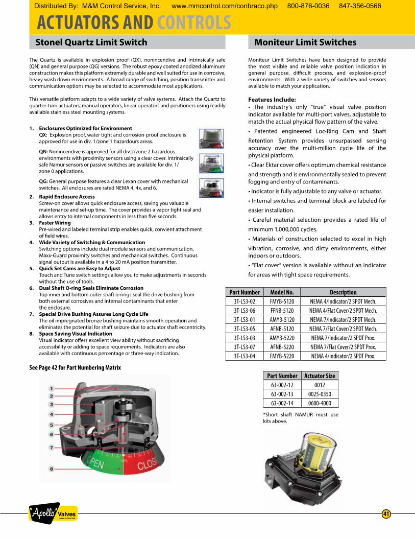
ACTUATORS AND CONTROLS
41
Part Number Model No. Description3T-LS3-02 FMYB-5120 NEMA 4/Indicator/2 SPDT Mech.3T-LS3-06 FFNB-5120 NEMA 4/Flat Cover/2 SPDT Mech.3T-LS3-01 AMYB-5120 NEMA 7/Indicator/2 SPDT Mech.3T-LS3-05 AFNB-5120 NEMA 7/Flat Cover/2 SPDT Mech.3T-LS3-03 AMYB-5220 NEMA 7/Indicator/2 SPDT Prox.3T-LS3-07 AFNB-5220 NEMA 7/Flat Cover/2 SPDT Prox.3T-LS3-04 FMYB-5220 NEMA 4/Indicator/2 SPDT Prox.
Part Number Actuator Size63-002-12 001263-002-13 0025-035063-002-14 0600-4000
*Short shaft NAMUR must use kits above.
Stonel Quartz Limit Switch Moniteur Limit Switches
1. Enclosures Optimized for Environment QX: Explosion proof, water tight and corrosion-proof enclosure is approved for use in div. 1/zone 1 hazardours areas.
QN: Nonincendive is approved for all div.2/zone 2 hazardous environments with proximity sensors using a clear cover. Intrinsically safe Namur sensors or passive switches are available for div. 1/ zone 0 applications.
QG: General purpose features a clear Lexan cover with mechanical switches. All enclosures are rated NEMA 4, 4x, and 6.
2. Rapid Enclosure Access Screw-on cover allows quick enclosure access, saving you valuable maintenance and set-up time. The cover provides a vapor tight seal and allows entry to internal components in less than five seconds.3. Faster Wiring Pre-wired and labeled terminal strip enables quick, convient attachment of field wires.4. Wide Variety of Switching & Communication Switching options include dual module sensors and communication, Maxx-Guard proximity switches and mechanical switches. Continuous signal output is available in a 4 to 20 mA position transmitter.5. Quick Set Cams are Easy to Adjust Touch and Tune switch settings allow you to make adjustments in seconds without the use of tools.6. Dual Shaft O-ring Seals Eliminate Corrosion Top inner and bottom outer shaft o-rings seal the drive bushing from both external corrosives and internal contaminants that enter the enclosure.7. Special Drive Bushing Assures Long Cycle Life The oil impregnated bronze bushing maintains smooth operation and eliminates the potential for shaft seizure due to actuator shaft eccentricity.8. Space Saving Visual Indication Visual indicator offers excellent view ability without sacrificing accessibility or adding to space requirements. Indicators are also available with continuous percentage or three-way indication.
See Page 42 for Part Numbering Matrix
The Quartz is available in explosion proof (QX), nonincendive and intrinsically safe (QN) and general purpose (QG) versions. The robust epoxy coated anodized aluminum construction makes this platform extremely durable and well suited for use in corrosive, heavy wash down environments. A broad range of switching, position transmitter and communication options may be selected to accommodate most applications.
This versatile platform adapts to a wide variety of valve systems. Attach the Quartz to quarter-turn actuators, manual operators, linear operators and positioners using readily available stainless steel mounting systems.
Moniteur Limit Switches have been designed to provide the most visible and reliable valve position indication in general purpose, difficult process, and explosion-proof environments. With a wide variety of switches and sensors available to match your application.
Features Include: • The industry’s only “true” visual valve position indicator available for multi-port valves, adjustable to match the actual physical flow pattern of the valve.
• Patented engineered Loc-Ring Cam and Shaft
Retention System provides unsurpassed sensing accuracy over the multi-million cycle life of the physical platform.
• Clear Ektar cover offers optimum chemical resistance
and strength and is environmentally sealed to prevent fogging and entry of contaminants.
• Indicator is fully adjustable to any valve or actuator.
• Internal switches and terminal block are labeled for
easier installation.
• Careful material selection provides a rated life of
minimum 1,000,000 cycles.
• Materials of construction selected to excel in high
vibration, corrosive, and dirty environments, either indoors or outdoors.
• “Flat cover” version is available without an indicator
for areas with tight space requirements.
Distributed By: M&M Control Service, Inc. www.mmcontrol.com/conbraco.php 800-876-0036 847-356-0566

ACTUATORS AND CONTROLS
42
Stonel Quartz Limit Switch - How to Order
Explosion proof Quartz Models (Aluminum Cover)Series
E North American (NEC/CEC) 02 (1) 3/4" NPT & SRA Red-‐Closed / Green-‐Open33 SST N.O. Switching Sensor Dual Module R International (IEC/ATEX) (1) 1/2" NPT SGA Green-‐Closed / Red-‐Open
F INMETRO 03 (1) 3/4" NPT & S1A T1 3-‐wayS* Stainless Steel North American (NEC/CEC) (2) 1/2" NPT S2A T2 3-‐way
92 DeviceNet VCT T* Stainless Steel International (IEC/ATEX) 05 (2) M20 S3A T3 3-‐way93 Foundation Fieldbus M* Stainless Steel INMETRO S4A T4 3-‐way96 AS-‐Interface 06 (3) M20 S5A T5 3-‐Way97 AS-‐Interface (w/ extended addressing) S0A No Indication
* Available w/ 03 or 06 conduit entry only SXA SpecialSCA Continuous
2V (2) SPDT Mechanical Switches2W (2) SPDT Gold Contact Mechanical Switches4V (4) SPDT Mechanical Switches4W (4) SPDT Gold Contact Mechanical Switches14 (2) DPDT Mechanical Switches5V Position Transmitter w/ (2) SPDT Mechanical Switches5W Position Transmitter w/ (2) SPDT Mechanical Switches
82 DeviceNet86 AS-‐Interface
Function Switch/Sensor Type2 (2) Switches P SPST Maxx-‐Guard4 (4) Switches L SPST Maxx-‐Guard (LED)5 Position Transmitter w/ (2) or No Switches G SPDT Maxx-‐Guard7 High Performance Position Transmitter w/ (2) or No Switches H SPDT Maxx-‐Guard8 Expeditor, Y or H switches only S SPDT Maxx-‐Guard (LED)
Y Expeditor Only (3)F PNP Solid State 3-‐Wire P&FX SST Sensor (LED)O No Switches
SeriesC North American (NEC/CEC) 02 (1) 3/4" NPT & SRA Red-‐Closed / Green-‐Open
33 SST N.O. Switching Sensor Dual Module D International (IEC/ATEX) (1) 1/2" NPT SGA Green-‐Closed / Red-‐Open44 Namur Sensors Dual Module I.S.; DIN 19234 03 (1) 3/4" NPT & S1A T1 3-‐way
(2) 1/2" NPT S2A T2 3-‐way05 (2) M20 S3A T3 3-‐way
92 DeviceNet VCT S4A T4 3-‐way93 Foundation Fieldbus 06 (3) M20 S5A T5 3-‐Way96 AS-‐Interface S0A No Indication97 AS-‐Interface (w/ extended addressing) SXA Special
SCA Continuous
82 DeviceNet86 AS-‐Interface
Sensors/SwitchesFunction Switch/Sensor Type
2 (2) Switches P SPST Maxx-‐Guard4 (4) Switches L SPST Maxx-‐Guard (LED)5 Position Transmitter w/ (2) or No Switches G SPDT Maxx-‐Guard7 High Performance Position Transmitter w/ (2) or No Switches H SPDT Maxx-‐Guard8 Expeditor, Y or H switches only S SPDT Maxx-‐Guard (LED)
Y Expeditor Only (3)F PNP Solid State 3-‐Wire P&FX SST Sensor (LED)O No Switches
J SPST (Passive)M SPDT (Passive)N P + F Namur Sensors
SeriesC General Purpose 02 (1) 3/4" NPT & SRA Red-‐Closed / Green-‐Open
2V (2) SPDT Mechanical Switches (1) 1/2" NPT SGA Green-‐Closed / Red-‐Open2W (2) SPDT Gold Contact Mechanical Switches 03 (1) 3/4" NPT & S1A T1 3-‐way4V (4) SPDT Mechanical Switches (2) 1/2" NPT S2A T2 3-‐way4W (4) SPDT Gold Contact Mechanical Switches 05 (2) M20 S3A T3 3-‐way14 (2) DPDT Mechanical Switches S4A T4 3-‐way
06 (3) M20 S5A T5 3-‐WayS0A No IndicationSXA SpecialSCA Continuous
QG
Nonincendive & Intrinsically Safe Quartz Models (Clear Cover)
General Purpose Quartz Models (Clear Cover)
QN
Function Enclosure Conduit Entries IndicatorMechanical Switches
Sensor Modules
Valve Communication Terminals (VCTs)
Expeditors (Proximity Type)
Intrinsically Safe Type
Conduit Entries Indicator
QX
Sensors/Switches
Sensors/Switches Enclosure Conduit Entries Indicator
Sensors/Switches
Mechanical Switches
Valve Communication Terminals (VCTs)
Sensor Modules
Expeditors (Proximity Type)
Enclosure
See price list or contact factory for Conbraco P/N and price.
Distributed By: M&M Control Service, Inc. www.mmcontrol.com/conbraco.php 800-876-0036 847-356-0566

ACTUATORS AND CONTROLS
43
VRC PositionersDIMENSIONAL DIAGRAMS
CONSTRUCTIONPart Materials
EnclosurePPA Composite, 300 Stainless Steel Port Rings, Cover and Mounting Bolts
Indicator Lens LEXAN™
InternalsPPA, PPS and PEEK Composites 300 Series Stainless Steel
Nickel Plated Brass Spool Valve Carpenter 70 Grade Stainless Steel
I/P Converter (VK02) VE ModelPPA Composite, TEFLON™ Coated Carbon Steel, Nickel Plated Carbon Steel, High Density Polyethylene DELRIN™
Signal Diaphragm/ O-Rings BUNA N
Note: See Price List for Apollo Part Numbers
PERFORMANCEParameter Specification
Resolution1.25% Maximum0.10% Typical
Repeatability99.75% Minimum99.90% Typical
Hysteresis0.50% Maximum0.25% Typical
Linearity 1.0% Maximum
Gain @80 psig250 Single Acting500 Double Acting
Air Consumption@80 psig
0.25 SCFM – Standard Flow Spool Valve0.45 SCFM – Maximum Flow Spool Valve
Temp. Range -40 to 150˚F/-40 to 65˚C
How to Order VRC Positioners
3PV -PREFIX POSITION INDICATOR & TYPE SPOOL VALVE PORT GAUGES POSITION TRANSMITTER LIMIT SWITCH3PV 0 = Flat Pneumatic 7 = Standard Flow 3 = No Gauges 0 = No Transmitter 0 = No Switch
1 = Flat Electro-Pneumatic 8 = Max Flow 4 = Brass Gauges F = 4-20MA Current K = Mechanical Switch5 = Dome Pneumatic 5 = SS Gauges Output 2-Wire M = Proximity Switch6 = Dome Electro-Pneumatic
Distributed By: M&M Control Service, Inc. www.mmcontrol.com/conbraco.php 800-876-0036 847-356-0566

ACTUATORS AND CONTROLS
44
PMV PositionersFEATURES & BENEFITS Simple design makes this product easy to understand, calibrate and repair.
Rugged construction provides operation in a variety of tough applications. Compact size minimizes space requirements. A complete package means the user can select the right positioner for his application.
A bright indicator makes it easy for operators to visually check valve position. Spool valve design requires very little maintenance. Electro-pneumatic unit eliminates the need for an extra product and additional connections. Recognized product name means a proven product with many years of service.
PRODUCT SPECIFICATIONSP2000/20 P5/EP5*
Connections: 1/4” 1/4”Supply Pressure: 120 psig 145 psigHysteresis: 0.5% 0.5%Linearity: 2.0% 0.5%Repeatability: 0.5% 0.5%Sensitivity: 0.5% 0.25%Input Signal: 4-20 mA 3-15, 4-20mATemperature - Standard: +5 - 175˚F +5 - 185˚FTemperature - Optional: +5 - 230˚F +5 - 230˚FWeight: 5.9 lbs. 2.9/4.1 lbs.Air Consumption @ 85 psig: 35/.71 scfm----------------------------------------.75 scfmAir Delivery @ 57 psig: 12/15.7 scfm 12.6 scfmGain Factor: 50/400 10,000
*PMV New Modular Unit P5-Pneumatic; EP5 Electropneumatic
Valve positioners are an excellent tool for increasing the gain of your valve package, often reducing your actuator size due to your increased ability to accurately control higher air deliveries, and the flexibility to add options and accessories to complete your control package’s performance.
Our standard positioners include both pneumatic and electropneumatic positioners. Electropneumatic Positioners may be used on either double acting or spring return actuators. The anodized aluminum housing provides excellent product integrity and good corrosion resistance. Options including special coatings, stainless steel housings, and a variety of accessory items which provide the flexibility to meet your most demanding control applications.
PART NUMBERSApollo Part #’s PMV Model #’s Description
3T-200-01 P-2000 Double Acting, Electro-Pneumatic, 13T-202-01 P-2020 Double Acting, Electro-Pneumatic, 23T-500-01 P5 Double Acting, Hi Capacity & Gain3T-250-01 EP5 Electro Pneumatic, Hi Capacity & Gain3T-250-02 EP5-EX Double Acting, Hi Capacity & Gain, Explosion Proof
1. Normal Capacity2. High Capacity3. Accessories such as pressure gauges, limit switches, transmitters, and potentiometers are available. Please consult the factory for pricing.
PMV MOUNTING KITS FOR APOLLO ACTUATORS Actuator Size Mounting Kit Material
AD/AS 0012 63-002-01 Stainless SteelAD/AS 0025-0350 63-001-89 Stainless SteelAD/AS 0600-4000 63-001-91 Stainless Steel
Distributed By: M&M Control Service, Inc. www.mmcontrol.com/conbraco.php 800-876-0036 847-356-0566
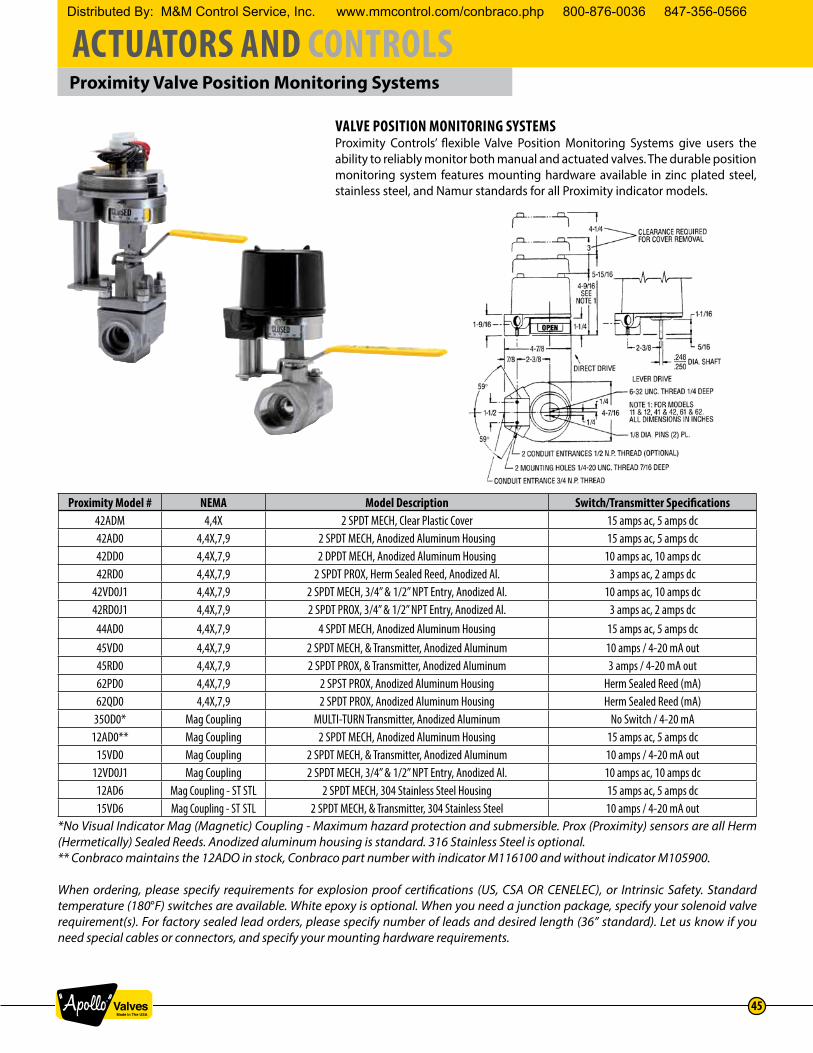
ACTUATORS AND CONTROLS
45
Proximity Valve Position Monitoring Systems
VALVE POSITION MONITORING SYSTEMSProximity Controls’ flexible Valve Position Monitoring Systems give users the ability to reliably monitor both manual and actuated valves. The durable position monitoring system features mounting hardware available in zinc plated steel, stainless steel, and Namur standards for all Proximity indicator models.
Proximity Model # NEMA Model Description Switch/Transmitter Specifications42ADM 4,4X 2 SPDT MECH, Clear Plastic Cover 15 amps ac, 5 amps dc42AD0 4,4X,7,9 2 SPDT MECH, Anodized Aluminum Housing 15 amps ac, 5 amps dc42DD0 4,4X,7,9 2 DPDT MECH, Anodized Aluminum Housing 10 amps ac, 10 amps dc42RD0 4,4X,7,9 2 SPDT PROX, Herm Sealed Reed, Anodized Al. 3 amps ac, 2 amps dc
42VD0J1 4,4X,7,9 2 SPDT MECH, 3/4” & 1/2” NPT Entry, Anodized Al. 10 amps ac, 10 amps dc42RD0J1 4,4X,7,9 2 SPDT PROX, 3/4” & 1/2” NPT Entry, Anodized Al. 3 amps ac, 2 amps dc44AD0 4,4X,7,9 4 SPDT MECH, Anodized Aluminum Housing 15 amps ac, 5 amps dc45VD0 4,4X,7,9 2 SPDT MECH, & Transmitter, Anodized Aluminum 10 amps / 4-20 mA out45RD0 4,4X,7,9 2 SPDT PROX, & Transmitter, Anodized Aluminum 3 amps / 4-20 mA out62PD0 4,4X,7,9 2 SPST PROX, Anodized Aluminum Housing Herm Sealed Reed (mA)62QD0 4,4X,7,9 2 SPDT PROX, Anodized Aluminum Housing Herm Sealed Reed (mA)
35OD0* Mag Coupling MULTI-TURN Transmitter, Anodized Aluminum No Switch / 4-20 mA12AD0** Mag Coupling 2 SPDT MECH, Anodized Aluminum Housing 15 amps ac, 5 amps dc
15VD0 Mag Coupling 2 SPDT MECH, & Transmitter, Anodized Aluminum 10 amps / 4-20 mA out12VD0J1 Mag Coupling 2 SPDT MECH, 3/4” & 1/2” NPT Entry, Anodized Al. 10 amps ac, 10 amps dc
12AD6 Mag Coupling - ST STL 2 SPDT MECH, 304 Stainless Steel Housing 15 amps ac, 5 amps dc15VD6 Mag Coupling - ST STL 2 SPDT MECH, & Transmitter, 304 Stainless Steel 10 amps / 4-20 mA out
*No Visual Indicator Mag (Magnetic) Coupling - Maximum hazard protection and submersible. Prox (Proximity) sensors are all Herm (Hermetically) Sealed Reeds. Anodized aluminum housing is standard. 316 Stainless Steel is optional.** Conbraco maintains the 12ADO in stock, Conbraco part number with indicator M116100 and without indicator M105900.
When ordering, please specify requirements for explosion proof certifications (US, CSA OR CENELEC), or Intrinsic Safety. Standard temperature (180°F) switches are available. White epoxy is optional. When you need a junction package, specify your solenoid valve requirement(s). For factory sealed lead orders, please specify number of leads and desired length (36” standard). Let us know if you need special cables or connectors, and specify your mounting hardware requirements.
Distributed By: M&M Control Service, Inc. www.mmcontrol.com/conbraco.php 800-876-0036 847-356-0566

ACTUATORS AND CONTROLS
46
OSHA Lockout Device
The Apollo® Lockout Tagout accessory for actuators complies with OSHA 1910.147 guidelines. It insures complete lockout capability in both the fully open or the fully closed position. Its design prevents accidental or malicious tampering of an automated valve’s orientation.
The housing is constructed in investment cast 316SS, the fasteners, the lock pin, and the coupling are made of 300 Series stainless steel. This rugged construction, plus two acetal bushings located above and below the coupling, assures the strength and support necessary to withstand the torque and torsion generated by the actuator mounted above.
The top and bottom of the housing feature ISO 5211 mounting patterns. This design allows the accessory to be fitted between existing actuators and stainless steel bracketry that also comply with the ISO 5211 standard.
Available in six sizes, it is the perfect compliment to the Apollo® Rack and Pinion Actuator and Apollo® Ball Valve. The design results in a safe automated package that will satisfy the concerns of the most discriminating safety engineer.
The lockout device may be used with electric actuators. However, caution should be exercised due to the possibility of motor burnout in an energized and locked position.
DIMENSION 3TL3000 3TL4000 3TL5060 3TL6570 3TL8000 3TL9000A 4.00 4.00 6.00 6.00 8.00 8.00B 3.00 3.00 4.25 4.25 6.00 6.00C 2.25 2.25 3.12 3.12 4.25 4.25D 1.75 1.75 2.37 2.37 3.50 3.50E 0.06 0.06 0.10 0.10 0.18 0.18F 2.00 2.00 3.00 3.00 4.00 4.00G 0.50 0.70 0.87 0.87 1.38 1.38H 1.02 1.02 1.75 1.75 2.50 2.50I 0.62 0.70 1.17 1.17 2.00 2.00
J(RAD.) 0.37 0.37 0.50 0.50 0.75 0.75K 0.96 0.96 1.50 1.50 2.50 2.50
L1 0.265 0.265 0.328 0.328 0.515 0.640L2 NA NA 0.390 0.390 NA NA
UNC1 1/4-2OUNC 1/4-2OUNC 5/16-18UNC 5/16-18UNC 1/2-2OUNC 5/8-11UNCUNC2 NA NA 0.390 0.390 NA NA
M1 B.C. 1.970 (F05) 1.970 (F05) 2.756 (F07)* 2.756 (F07) 4.920 (F12) 5.510 (F14)M2 B.C. NA NA 4.016 (F10) 4.016 (F10)* NA NA
XT (MAX.) 0.540 0.690 0.955 1.080 1.325 1.780XB (MIN.) 0.551 0.710 0.985 1.105 1.420 1.890
CT .430/.432 .547/.550 .744/.747 .862/.865 1.056/1.059 1.413/1.416CB .433/.435 .551/.553 .748/.750 .866/.868 1.060/1.063 1.419/1.422
WEIGHT 3.65 3.75 9.90 10.40 28.90 29.50*F Patterns Designated are Conbraco’s Standard Mounting Arrangement
Distributed By: M&M Control Service, Inc. www.mmcontrol.com/conbraco.php 800-876-0036 847-356-0566

ACTUATORS AND CONTROLS
47
Apollo Ball Valves
VALVE MOUNTINGMounting of Apollo® actuators to quarter turn valves is a straight forward task. Conbraco provides stainless steel brackets and couplings that are precision made to fit each of its Apollo® valve and actuator combinations. The simplicity of valve mounting hardware is deceptive and may cause carelessness in the assembly operation.
CAUTIONIt is mandatory that the actuator to valve mounting procedure be performed by personnel that have been properly trained and informed of the importance of this assembly operation.
Conbraco’s brackets and couplings have been engineered to have the required strength and precision fit to insure reliable valve operation. Each mounting kit has all the required components to mate specific valves and actuators (refer to the mounting kit selection guide).
CAUTIONBrackets and couplings of lesser quality can expose the stem of the valve to side loads that will ultimately cause premature stem leakage. It is essential that the actuator to valve mounting be treated as a critical assembly operation. All brackets and couplings must be properly aligned prior to tightening the attachment bolts. The assembly should undergo an operational test to insure that there is no binding during operation. There must be no discernible flexing of the bracket. If either is noted corrective action must be taken before the assembly is considered acceptable for use.
ALL AUTOMATED VALVES must undergo an operational test to insure that both the valve and actuator function properly. The valve must be properly aligned in both the open and closed positions. Spring return actuators must perform their intended safety function such as: fail closed, fail open. Modulating actuators should operate the valve in the correct direction in response to the required instrument signal.
BALL VALVE TORQUEBefore an actuator can be selected, the in-service torque requirement of the valve must be determined. The in-service valve torque is influenced by many factors. Packing and seating materials are fundamental to the construction of the valve and therefore establish the basic required torque. Service conditions which include differential pressure, frequency of operation and flow media also have a significant effect on the valve’s in-service torque. Refer to the Torque Constants Chart for valve torque requirements under defined conditions. The torque required to operate a ball valve is the result of friction between the moving and stationary components of the valve. The stem to packing friction and the ball to seat friction combine to establish the minimum torque requirement. Conbraco recommends the use of a stainless steel ball and stem on automated valves.
LONG STAND STILL TORQUE (LSST)Common to soft seated ball valves is the phenomena of Long Stand Still Torque (LSST). For floating ball valves, LSST is typically twice the normal rated torque. The phenomena occurs when a valve remains idle for an extended period of time, typically a month or more, but the time period can vary by application. Even if “normal” operation is daily or even more frequent, if the valve sits idle LSST still need to be taken into account when sizing an actuator. Once the valve has been operated a couple of times, the operating torque returns to normal levels.
Distributed By: M&M Control Service, Inc. www.mmcontrol.com/conbraco.php 800-876-0036 847-356-0566

ACTUATORS AND CONTROLS
48
Apollo Ball Valves (cont’d)
BALL & SEATValve torque is primarily dependent on the friction between the moving ball and the stationary seat. Seating material and surface finish of the ball establish the basic frictional characteristics of the combination. Service conditions also play a major roll in modifying the effects of friction. A floating ball valve utilizes the difference between the upstream and downstream pressures to force the ball into the downstream seat. When this force exceeds the forces in the original assembly, the torque required to rotate the ball increases. Process media may also increase or decrease the friction between the ball and seat. To insure reliable actuator selection, the service conditions of the installed valve must be carefully determined and considered for their effect on torque.
STEM & PACKINGStem torque is primarily dependent on the frictional characteristics of the packing material and the tightness of the packing adjustment. Proper adjustment of the packing is important not only to the leak tight performance of the valve but also minimizes the operating torque. Tightening the packing more than is required to establish a proper seal, only increases torque requirements and stem wear. Packing adjustment can be abused to the point that a properly selected actuator may not be able to operate the valve. Stem packing friction is essentially unaffected by the media and operating pressures within the valve.
-24/-29 GRAPHITE STEM PACKING ADDERThe selection of graphite packing contributes significantly to the operating torque of a valve. The friction factor for graphite is a magnitude different than that of PTFE based packings. The contribution to torque is a function of the stem diameter and is reflected in each of the following tables. When selecting either the -24, -29 or -65 options use the appropriate adder listed in the table for each valve as a direct increase to the base torque constant.
BREAKWAY TORQUETorque required to initiate the opening of a valve from the fully closed position. This is the highest torque requirement anywhere within the Apollo® Ball Valve’s rotation. The Torque Constants Chart lists breakaway torques for Apollo® valves under defined operation conditions.Note: For double acting actuators, the torque output at the given air supply pressure must exceed the breakaway torque of the valve.
CLOSING TORQUETorque required to rotate the valve from the open position, into the fully closed position. A conservative approach is taken when determining closing torque because operating conditions have a significant effect on its value. It is safest to assume that closing torque is equal to breakaway torque. In actual service conditions the closing torque may be less, but this margin is used as a sizing safety factor.
GUIDELINES FOR DETERMINING IN-SERVICE VALVE TORQUE Actual service conditions must be considered when determining a valve’s required torque. Torque Adjustment Factors have been established to convert the Torque Constant value to an in-service torque. Multiple Torque Adjustment Factors may be required to establish the proper in-service torque requirement. All valve torque determinations begin with the Torque Constant value at the appropriate differential pressure. Adjustment factors must be used to determine the in-service valve torque requirement (see page 52, Torque Adjustment Factors Chart). Each applicable adjustment factor is applied to the value from the Torque Constants chart. The sum of all appropriate adjustments of the valve’s torque are added to the original value from the Torque Constants chart. The result is the in-service torque requirement. This torque value is to be used in actuator selection.
Note: For fail closed applications, the closing torque must be exceeded by the “spring end” force of the actuator. For fail open applications, the closing torque must be exceeded by the “air end” (at the given supply pressure) force of the actuator.
Distributed By: M&M Control Service, Inc. www.mmcontrol.com/conbraco.php 800-876-0036 847-356-0566

ACTUATORS AND CONTROLS
49
Apollo Ball Valves
TORQUE CONSTANTS FOR APOLLO END ENTRY VALVE (1), (2)TORQUE CONSTANT (LB-IN) AT DIFFERENTIAL PRESSURE INDICATED (PSIG)
Differential Pressure (psig) 200 400 600 800 1000 1500 LSST*** -24/-29 AdderValve Model Size (in.-lbs) (in.-lbs)
STD PORT70-64X71-14X76-10X76-60X89-14X
399-10X
1/4 - 1/2 35 35 40 43 46 48 70 453/4 50 50 54 59 62 64 100 45
1 101 101 103 106 116 130 202 561-1/4 171 171 205 216 246 286 342 961-1/2 192 192 216 265 280 311 384 96
2 271 271 276 300 309 354 542 962-1/2 & 3 715 715 790 1200 1430 96
FULL PORT BRONZE 77-14X
1/4 - 1/2 35 35 40 70 453/4 74 74 84 148 56
1 234 234 250 468 561-1/4 286 286 321 552 561-1/2 357 357 398 714 96
2 650 650 722 1300 962-1/2 & 3 715 715 790 1430 111
FULL PORT BRONZE77D-14X
1/2 25 25 25 25 503/4 55 55 55 55 110
1 87 87 87 87 1741-1/2 120 120 120 120 240
2 280 280 280 280 560
**STD PORT**71-ARX-64
89-ARX-6476-ARX-64
1/4 - 1/2 26 27 28 30 32 35 50 453/4 50 52 54 57 60 64 100 45
1 86 88 90 94 97 110 170 561-1/4 140 145 156 160 172 194 280 961-1/2 164 173 186 195 201 235 320 96
2 230 258 270 310 350 460 440 962-1/2 495 576 680 790 900 900 96
3 540 700 820 920 1030 1000 96
*FULL PORT**77-ARX-64
1/4 - 1/2 50 52 54 100 453/4 86 88 90 170 56
1 148 160 180 280 561-1/2 300 310 340 580 96
2 355 420 563 680 96
FULL PORT3-PIECE
82-14X & 24X
1/4 - 1/2 78 78 90 156 563/4 156 156 178 312 56
1 208 208 230 416 961-1/4 234 234 276 468 961-1/2 350 350 390 700 96
2 715 715 755 1430 963 710 1100 2924 1052 1540 292
FULL PORT3-PIECE
83A-14X & 24X83B-14X & 24X86A-10X & 20X86B-10X & 20X
1/4 - 1/2 38 39 41 42 43 49 75 453/4 61 62 63 63 67 79 121 68
1 97 104 110 117 124 141 180 681-1/4 182 198 213 228 243 281 335 961-1/2 182 198 213 228 243 281 335 96
2 275 388 402 466 529 688 422 127FULL PORT 3-PIECE
83R-108-01 & 83R-100-0186R-108-01 & 86R-100-01
2 715 715 755 800 912 1024 1430 963 1030 1030 1087 1148 1212 2060 201
* Torques tested with multifilled seats. Does not require torque adjustment of -20%.** 71-ARX-64 and 77-ARX-64 rated to 600 psig maximum.*** LSST - Long Stand Still Torque
Note 1: Constants are used to determine the in-service torque requirements of Apollo Valves.Note 2:Constants are based on RPTFE seats, and clean dry air at the stated differential pressure.
Distributed By: M&M Control Service, Inc. www.mmcontrol.com/conbraco.php 800-876-0036 847-356-0566

ACTUATORS AND CONTROLS
50
Apollo Ball Valves
TORQUE CONSTANTS FOR APOLLO PEEK SEATED 83B/86BWITH GRAPHITE STEM PACKINGTORQUE CONSTANT (LB-IN) AT DIFFERENTIAL PRESSURE INDICATED (PSIG)
Differential Pressure (psig): 200 400 600 800 1000 1200 1400 1500 LSSTValve Model Size (in.-lbs)
FULL PORT3-PIECE
83B/86B
1/4 - 1/2 75 80 86 91 98 105 111 118 1123/4 130 150 170 177 185 194 204 210 195
1 250 263 276 289 302 315 328 345 3751-1/4 420 463 506 549 592 635 678 720 6301-1/2 420 463 506 549 592 635 678 720 630
2 840 922 1004 1086 1168 1250 1332 1410 1260Caution: 2” PEEK seated valves operating at pressures higher than 1000 psig. should be automated or have a gear operator installed. Lever operation is not suggested. All values are stated in (in. lbs.)TORQUE CONSTANTS FOR APOLLO FLANGED BALL VALVES
Valve Series SizeWORKING PRESSURE (PSIG)
0 100 200 300 400 500 600 700 740 LSST -24 Adder(in.-lbs) (in.-lbs)
87A-100’S88A-140’S87B-100’S88B-100’S
1-1/2” SP 150 132 144 155 167 264 682” SP 150 176 193 211 228 352 96
2-1/2” SP 150 231 254 277 300 462 1273” SP 150 253 327 402 476 506 1274” SP 150 850 860 875 890 1700 2926” SP 150 1325 1345 1370 1400 2650 2928” SP 150 2200 2494 2788 3081 4400 661
10” SP 150 3300 3580 3860 4140 6600 661
87A-200’S88A-240’S
1/2” FP 150 22 22 22 22 44 453/4” FP 150 39 43 47 51 77 68
1” FP 150 132 144 155 167 264 681-1/2” FP 150 176 193 211 228 352 96
2” FP 150 231 254 277 300 462 1272-1/2” FP 150 253 327 402 476 506 127
3” FP 150 850 860 875 890 1700 2924” FP 150 1325 1345 1370 1400 2650 2926” FP 150 2200 2494 2788 3081 4400 6618” FP 150 3300 3580 3860 4140 6600 661
10” FP 150 4400 5059 5718 6377 8800 98812” FP 150 4950 8300 11650 15000 9900 988
87A-700’S88A-740’S
1-1/2” SP 300 132 144 155 167 178 190 201 213 217 264 682” SP 300 176 193 211 228 245 262 280 297 304 352 96
2-1/2” SP 300 231 254 277 300 323 346 369 392 401 462 1273” SP 300 253 327 402 476 551 625 700 774 804 506 1274” SP 300 850 860 875 890 910 950 1030 1110 1142 1700 2926” SP 300 1325 1345 1370 1400 1430 1474 1615 1756 1812 2650 2928” SP 300 2200 2494 2788 3081 3375 3669 3963 4257 4374 4400 661
10” SP 300 3300 3580 3860 4140 4420 4700 4980 5260 5372 6600 661
87A-900’S88A-940’S
1/2” FP 300 22 22 22 22 23 23 23 23 23 44 453/4” FP 300 39 43 47 51 55 59 63 67 69 77 68
1” FP 300 132 144 155 167 178 190 201 213 217 264 681-1/2” FP 300 176 193 211 228 245 262 280 297 304 352 96
2” FP 300 231 254 277 300 323 346 369 392 401 462 1272-1/2” FP 300 253 327 402 476 551 625 700 774 804 506 127
3” FP 300 850 860 875 890 910 950 1030 1110 1142 1700 2924” FP 300 1325 1345 1370 1400 1430 1474 1615 1756 1812 2650 2926” FP 300 2200 2494 2788 3081 3375 3669 3963 4257 4374 4400 6618” FP 300 3300 3580 3860 4140 4420 4700 4980 5260 5372 6600 661
10” FP 300 4400 5059 5718 6377 7036 7696 8355 9014 9277 8800 98812” FP 300 4950 8300 11650 15000 18349 21699 25049 28399 29739 9900 988
Distributed By: M&M Control Service, Inc. www.mmcontrol.com/conbraco.php 800-876-0036 847-356-0566

ACTUATORS AND CONTROLS
51
Apollo Ball Valves
TORQUE CONSTANTS FOR APOLLO CLASS 600 FULL PORT FLANGED VALVES
seat material sizeworking pressure (psig) -24
ADDER200 400 600 800 1000 1200 1400 1500 LSST*
Devlon V-API
1" 166 189 211 233 256 275 292 300 288 N/A1.5" 253 273 292 312 331 351 370 380 468 N/A2" 686 698 710 721 732 744 755 761 1350 N/A
2.5" 1150 1190 1231 1272 1313 1353 1395 1415 2256 N/A3" 1893 2030 2167 2304 2440 2577 2714 2782 3512 N/A4" 2406 2681 2957 3232 3508 3784 4060 4197 4260 N/A6" 7935 8280 8625 8970 9135 9660 10005 10178 13638 N/A8" 8282 8868 9454 10041 10627 11213 11799 12092 15978 N/A
PEEK
1" 184 204 224 245 264 283 304 314 328 N/A1.5" 379 399 420 439 460 479 500 509 468 N/A2" 882 968 1054 1140 1225 1313 1399 1481 1323 N/A
2.5" 1256 1320 1384 1448 1512 1576 1640 1672 2384 N/A3" 2378 2588 2797 3007 3217 3427 3637 3741 4336 N/A4" 5771 6832 7892 8952 10012 11073 12133 12663 9422 N/A6" 6983 8675 10368 12061 13753 15446 17139 17985 10580 N/A8" 8586 12822 17058 21294 25531 29767 34003 36121 12936 N/A
UHMWPE
1" 155 178 201 219 222 224 228 228 264 N/A1.5" 211 245 280 305 310 315 318 318 352 N/A2" 428 454 479 505 531 556 582 594 806 N/A
2.5" 447 467 486 506 525 875 N/A3" 1139 1224 1310 1396 1482 2106 N/A4" 1506 1638 1820 2002 2184 2600 N/A6" 3133 3487 3842 5558 N/A8" 3814 4354 4894 7088 N/A
MULTISEAL
1" 155 180 205 222 227 231 233 234 264 1021.5" 213 245 280 308 316 322 326 326 354 1442" 313 356 400 444 487 531 575 597 538 191
2.5" 410 437 465 493 520 791 1913" 875 890 1030 1151 1228 1112 2924" 1506 1584 1683 1781 1880 2776 2926" 2788 3375 3963 4824 6618" 4836 5175 5514 8993 988
PTFE
1" 155 178 201 220 223 227 230 230 264 1021.5" 211 245 280 305 310 315 320 320 352 1442" 418 429 439 450 460 471 481 487 815 191
2.5" 364 389 413 438 463 703 1913" 875 890 1030 1151 1228 878 2924" 1506 1562 1617 1672 1728 2908 2926" 2788 3375 3963 3051 6618" 4207 4622 5038 7585 988
Caution: For torque constants in the highlighted areas, manual valve operation is not suggested. Automated and gear operated
assembly options are available. All values are stated in (in. lbs)
REV. 5-27-15
Distributed By: M&M Control Service, Inc. www.mmcontrol.com/conbraco.php 800-876-0036 847-356-0566

ACTUATORS AND CONTROLS
52
BALL VALVE TORQUE ADJUSTMENT FACTORSPROVISION CONDITION FACTOR
TYPE OF OPERATIONON/OFF SERVICE 0MODULATING SERVICE 0.25
PROCESS MEDIA
LIQUID, CLEAN PARTICLE FREE 0LIQUID, DIRTY, SLURRY, RAW WATER 0.3 to 0.8LIQUID, BLACK LIQUOR, LIME SLURRY 0.8LIQUID, OIL, LUBRICATING 0LIQUID, VISCOUS, MOLASSES 0.3GAS, CLEAN & WET 0GAS, DRY 0.3 to 0.5GAS, DIRTY, AIR SLURRY, NATURAL GAS 0.5 to 1OXYGEN, CHLORINE 0.5SUPERHEATED STEAM, SATURATED STEAM Refer to Process Temp.
FREQUENCYOF OPERATION**
ONCE PER DAY OR MORE 0ONCE PER WEEK 0.2ONCE PER MONTH 0.5Less than once per month (LSST) 1
PROCESSTEMPERATURE
APPLICATIONS ABOVE 225 DEG F 0.50APPLICATIONS BELOW -20 DEG F 0.25
VALVE SEATINGMATERIAL
PTFE 0*MULTIFILL 0*PEEK Contact Factory*UHMWPE Contact Factory
OPTION -49 -57 -67 -90
LIVE LOADED VALUES 0.2ASSEMBLED DRY 0.3OXYGEN CLEANED 0.3CLEANED FOR INDUSTRIAL GAS 0.3DOUBLE PACKED EXTENDED BONNET 0.2
CUSTOMER SPECIFIED PRESCRIBED SAFETY FACTOR 0.2 to 2
* Do not consider when calculating Top Entry Valve Torques. Apply all applicable Torque Adjustment Factors to the Valve** If accounting for LSST, disregard frequency of operation.
Example:To find adjusted torque: 1” 76-AR5-64 used on Oxygen service once per week to once per month. Find the torque constant of the valve at 200 psig DP, then add together the adjustment factors, and add 1 to that number. Then multiply the sum of the adjustment times the torque. 86” lbs x (.5 + .5 + 1) = 172” lbs. adjusted torque.
Apollo Ball Valves
TORQUE CONSTANTS FOR TOP ENTRY BALL VALVES
Seats Valve SizeStd. Port(Inches)
Valve SizeFull Port(Inches)
Differential Pressures (psig) (In.-Lbs.)
100 285 500 740 1480 LSST* Grafoil®Adder
5 1/2 thru 1 1/2 thru 3/4 85 110 140 180 290 170 686** 1-1/2 1 205 260 330 415 660 410 96C 2 1-1/2 350 430 550 735 1,200 700 127D 3 2 950 1,250 1,650 2,000 3,200 1,900 245G 4 3 2,000 2,500 3,300 4,100 6,500 4,000 399L 6†† 4†† 5,300 6,700 8,200 11,400 18,000 10,600 661M 8†† 6†† 11,000 14,000 18,500 25,000 36,000 22,000 900U** 10†† 8†† 18,500 22,000 30,000 40,000 62,000 37,000 1,326
1/2 thru 1 1/2 thru 3/4 115 160 210 260 450 230 684 1-1/2 1 270 370 480 590 1,000 540 968 2 1-1/2 475 650 860 1,050 1,750 950 1279 3 2 1,250 1,850 2,400 2,950 4,900 2,500 245B 4†† 3†† 2,700 3,700 4,900 5,900 10,000 5,400 399H 6†† 4†† 7,410 10,100 13,400 16,400 25,300 14,800 661N 8†† 6†† 15,000 20,000 26,000 34,500 56,000 30,000 900
10†† 8†† 25,000 32,000 45,000 60,000 96,000 50,000 1,326*LSST - Long Stand Still Torque**Rated torque for #6 and U seat add 30%†Rated torque for #9 ceramic seat is to be increased by 10%††Gear operator or actuation recommended
Distributed By: M&M Control Service, Inc. www.mmcontrol.com/conbraco.php 800-876-0036 847-356-0566

ACTUATORS AND CONTROLS
53
Apollo Butterfly Valves
DOUBLE ACTING ACTUATOR: AIR TO OPEN, AIR TO CLOSE√ Choose an actuator whose output torque at the given air supply is greater than the butterfly valve’s seating/ unseating torque.
√ Unseating torque is also known as the breakaway torque.
√ Seating torque is also known as the closing torque.
SPRING RETURN FAIL CLOSED: AIR TO OPEN, SPRING TO CLOSE√ Select an actuator whose ending spring stroke is greater than the butterfly valve’s seating/unseating torque. √ Select an actuator whose starting air stroke is greater than the butterfly valve’s seating/unseating torque at the given air supply pressure.
√ Above must be found on the same spring set line.
SPRING RETURN FAIL OPEN: AIR TO CLOSE SPRING TO OPEN√ Select an actuator whose end of air stroke is greater than the butterfly valve’s seating/unseating torque at the given air supply pressure.
√ Select an actuator whose start of spring stroke is greater than the butterfly valve’s seating/unseating torque.
√ Above must be found on the same spring set line. See Actuator Part Numbering System-”F” Suffix for Fail Open
BUTTERFLY VALVE ACTUATOR SIZING PROCEDURES
OPERATING FREQUENCYThe first operation of a valve after a sustained period of closure will require above normal torque.
LUBRICATING CHARACTERISTICS OF FLOW MEDIAJudge your flow media on this basis-better than or worse than water. Examples of lubricating media are: water, lubricating oils, aqueous process flow, beverage service, etc. Examples of non-lubricating media are: air, dry gases, dry bulk services, solvents, diesel oil, etc.
CONDITION OF DISC EDGE AND SEATAn iron disc in corrosive service will corrode. This corrosion deposits a build-up on the disk edge and raises required torque. Similar flow media deposits on the seat material can increase torque or prevent proper valve operation.
TEMPERATURE EXTREMESSustained operating temperatures approaching the upper or lower limits of the seat material will increase required torque. Refer to the seat temperature range on Apollo® Butterfly Valve Seat Materials page in the catalog. Consult the factory for anticipated torque increase of certain seat materials due to temperature extremes.
ELASTOMER SWELLCertain elastomers tend to swell from contact with some chemicals. This elastomer swell will increase required torque.
The wide selection of Apollo® Available Materials of Construction will allow you to choose the correct butterfly valve materials for your service. All of the above Torque Affecting Factors can be accommodated with the correct choice of materials. Consult the factory for assistance in choosing the correct torque value for your service.
NOTE: Please consult the material selection guide for trim recommendations. Please consult the factory for proper sizing of Apollo® actuators.
FACTORS AFFECTING SEATING AND UNSEATING TORQUE AND APPLICATION GUIDELINES
Distributed By: M&M Control Service, Inc. www.mmcontrol.com/conbraco.php 800-876-0036 847-356-0566

ACTUATORS AND CONTROLS
54
Apollo High Performance Butterfly Valves
TORQUE CONSTANTS FOR APOLLO DOUBLE OFFSET HIGH PERFORMANCE BUTTERFLY VALVES Soft Seat – Torque Rating (In-Lbs)
SIZE PSIGCLASS 150 CLASS 300 CLASS 600
∆P=100 ∆P=150 ∆P=200 ∆P=285 ∆P=100 ∆P=150 ∆P=200 ∆P=285 ∆P=740 ∆P=150 ∆P=500 ∆P=800 ∆P=1000 ∆P=1200 ∆P=14802" in-lbs 204 230 266 332 248 332 381 425 531 – – – – – –
2.5" in-lbs 239 283 319 398 301 398 443 478 575 – – – – – –3" in-lbs 257 301 345 434 327 434 487 540 664 407 513 841 974 1,106 1,2834" in-lbs 398 469 531 664 469 664 761 867 1,106 620 841 1,540 1,823 2,106 2,4875" in-lbs 558 655 743 929 620 885 1,062 1,239 1,664 – – – – – –6" in-lbs 726 850 974 1,212 858 1,221 1,505 1,779 2,460 1,912 2,673 5,080 6,045 7,009 8,3198" in-lbs 1,328 1,549 1,770 2,213 1,646 2,354 2,921 3,487 4,868 3,177 4,437 8,434 10,036 11,638 13,806
10" in-lbs 2,213 2,575 2,947 3,682 2,575 3,682 4,691 5,699 8,142 4,788 6,682 12,709 15,116 17,523 20,79812" in-lbs 2,867 3,345 3,823 4,779 3,629 5,177 6,522 7,877 11,151 – – – – – –14" in-lbs 4,938 5,761 6,584 8,231 6,053 8,646 11,186 13,735 19,913 – – – – – –16" in-lbs 6,903 8,054 9,204 11,505 8,461 12,080 14,788 17,496 24,072 – – – – – –18" in-lbs 9,717 11,337 12,956 16,196 11,903 17,010 20,461 23,913 32,303 – – – – – –20" in-lbs 12,930 15,089 17,240 21,550 15,842 22,629 26,816 30,993 41,153 – – – – – –24" in-lbs 19,859 23,169 26,479 33,099 24,329 34,754 40,595 46,436 60,623 – – – – – –
Under certain conditions, hydrodynamic torque can meet or exceed seating and unseating torques. When designing valve systems, hydrodynamic torque must be considered to help ensure correct selection of actuation.
Fire Safe Seat – Torque Rating (In-Lbs)
SIZE PSIGCLASS 150 CLASS 300 CLASS 600
∆P=100 ∆P=150 ∆P=200 ∆P=285 ∆P=100 ∆P=150 ∆P=200 ∆P=285 ∆P=740 ∆P=150 ∆P=500 ∆P=800 ∆P=1000 ∆P=1200 ∆P=14802" in-lbs 434 504 584 726 504 726 770 814 929 – – – – – –
2.5" in-lbs 460 540 620 770 540 770 823 885 1,018 – – – – – –3" in-lbs 584 681 779 974 681 974 1,035 1,097 1,257 866 1,208 1,549 1,788 2,027 2,3544" in-lbs 708 832 947 1,186 832 1,186 1,248 1,319 1,478 1,402 1,887 2,372 2,797 3,230 3,8145" in-lbs 965 1,124 1,283 1,602 1,133 1,620 1,894 2,177 2,850 – – – – – –6" in-lbs 1,345 1,566 1,788 2,239 1,584 2,257 2,531 2,805 3,478 7,077 8,455 9,832 11,691 13,558 16,0898" in-lbs 2,089 2,443 2,788 3,487 2,513 3,584 4,160 4,735 6,133 11,400 13,616 15,833 18,833 21,833 25,913
10" in-lbs 3,283 3,832 4,381 5,478 4,027 5,753 6,673 7,602 9,841 17,542 20,949 24,355 28,975 33,595 39,86912" in-lbs 5,168 6,036 6,894 8,620 6,230 8,894 10,470 12,045 15,877 – – – – – –14" in-lbs 6,912 8,062 9,213 11,514 8,363 11,948 14,426 16,904 22,913 – – – – – –16" in-lbs 8,770 10,231 11,700 14,620 10,655 15,222 18,682 22,152 30,559 – – – – – –18" in-lbs 12,567 14,664 16,762 20,948 15,178 21,683 27,541 33,409 47,640 – – – – – –20" in-lbs 16,859 19,674 22,479 28,099 20,196 28,851 37,993 47,126 69,322 – – – – – –24" in-lbs 25,072 29,249 33,426 41,781 30,046 42,923 56,622 70,331 103,607 – – – – – –
added 6-29-15
Distributed By: M&M Control Service, Inc. www.mmcontrol.com/conbraco.php 800-876-0036 847-356-0566

ACTUATORS AND CONTROLS
55
Apollo Resilient Seated Butterfly Valves
SEATING AND UNSEATING TORQUE APOLLO® RESILIENT SEATED BUTTERFLY VALVESWD141, LD141, WD145, LD145, LC149 Series
Valve Size (In.) Differential Pressure (psid)
50Bushing PTFE
100Bushing PTFE
150Bushing PTFE
200Bushing PTFE
2 100 106 111 1172 1/2 150 163 176 189
3 207 220 232 2444 290 323 357 3905 423 481 540 5986 599 691 783 8758 1060 1183 1307 1430
10 1671 1872 2074 227512 2568 2795 3023 325014 2640 3070 3500 -16 4260 4880 5500 -18 6287 7243 8200 -20 8360 9180 10000 -24 15427 16813 18200 -30 31200 32550 33930 -
All torque values shown on chart are for wet (water and other non-lubricating media) on-off service. For dry (non-lubricating, dry gas media), multiply values by 1.15. For lubed service (clean, nonabrasive lubricating media), multiply values by 0.85.
Under certain conditions, hydrodynamic torque can meet or exceed seating and unseating torques. When designing valve systems, hydrodynamic torque must be considered to help ensure correct selection of actuation.
* ALL PUBLISHED BUTTERFLY TORQUE CHARTS HAVE NO BUILT-IN SAFETY FACTORS. A PRESCRIBED 25% SAFETY FACTOR IS RECOMMENDED!
Conbraco Industries, Inc. warrants, to its initial purchaser only, that its products which are delivered to this initial purchaser will be of the kind described in the order or price list and will be free of defects in workmanship or material for a period of FIVE years from the date of delivery to you, our initial purchaser. This warranty applies to Apollo brand product with “Made in the USA” markings only.
Should any failure to conform to this warranty appear within FIVE years after the date of the initial delivery to our initial purchaser, Conbraco will, upon written notification thereof and substantiation that the goods have been stored, installed, maintained and operated in accordance with Conbraco’s recommendations and standard industry practice, correct such defects by suitable repair or replacement at Conbraco’s own expense.
APOLLO INTERNATIONAL PRODUCTS: Conbraco Industries, Inc. warrants its International products, to its initial purchaser only, that its international products which are delivered to this initial purchaser will be of the kind described in the order or price list and will be free of defects in workmanship or material for a period of TWO years from the date of delivery to you, our initial purchaser.
THIS WARRANTY IS EXCLUSIVE AND IS IN LIEU OF ANY IMPLIED WARRANTY OF MERCHANTABILITY, FITNESS FOR A PARTICULAR PURPOSE OR OTHER WARRANTY OF QUALITY, WHETHER EXPRESSED OR IMPLIED, EXCEPT THE WARRANTY OF TITLE AND AGAINST PATENT INFRINGEMENT. Correction of non-conformities, in the manner and for the period of time provided above, shall constitute fulfillment of all liabilities of Conbraco to our initial purchaser, with respect to the goods, whether based on contract, negligence, strict tort or otherwise. It is the intention of Conbraco Industries, Inc. that no warranty of any kind, whether expressed or implied shall pass through our initial purchaser to any other person or corporation.
LIMITATION OF LIABILITY: Conbraco Industries, inc. SHALL NOT UNDER ANY CIRCUMSTANCES BE LIABLE FOR SPECIAL OR CONSEQUENTIAL DAMAGES SUCH AS, BUT NOT LIMITED TO, DAMAGES OR TO LOSS OF OTHER PROPERTY OR EQUIPMENT, LOSS OF PROFITS OR REVENUE, COST OF CAPITAL, COST OF PURCHASED OR REPLACEMENT GOODS, OR CLAIMS OF CUSTOMERS OF OUR INITIAL PURCHASER. THE REMEDIES OF OUR INITIAL PURCHASER, AND ALL OTHERS, SET FORTH HEREIN, ARE EXCLUSIVE, AND THE LIABILITY OF CONBRACO WITH RESPECT TO SAME SHALL NOT, EXCEPT AS EXPRESSLY PROVIDED HEREIN, EXCEED THE PRICE OF THE GOODS UPON WHICH SUCH LIABILITY IS BASED.
* It is the end user’s responsibility to confirm that items intended for use satisfy local codes and standards.
WARRANTY AND LIMITATIONS OF LIABILITY
Distributed By: M&M Control Service, Inc. www.mmcontrol.com/conbraco.php 800-876-0036 847-356-0566