Embed Size (px)
Citation preview

::::::::::::::::::::::: ~~t~~t~~~}} ........................ . :.:.:.:.:.:.:.:.:.:.:. :::::::.: ..... :.::::::: • '". .. .. .o." ~ .. ::~ .;:: '".o ". t. ".o.
...... ... .......... ...... . ........ . ................... .. .................... .. ...................... .. .................... ..
::::::::i::::::ii::::::
MSC-D4822
NATIONAL AERONAUTICS AND SPACE ADMINISTRATION
APOLLO 15
3D-DAY FAILURE AND ANOMALY LISTING REPORT
. :.~~" ·4 t . .~. :".
1 ......
MANNED SPACECRAFT CENTER HOUSTON,TEXAS
SEPTEMBER 1971

MSc-04822
APOLLO 15
30-DAY FAILURE AND ANOMALY LISTING REPORT
PREPARED BY
Mission Evaluation Team
APPROVED BY
James Colonel, USAF
Manager, Apollo Spacecraft Program
NATIONAL AERONAUTICS AND SPACE ADMINISTRATION
MANNED SPACECRAFT CENTER
HOUSTON, TEXAS
September 1971

1
1.0 INTRODUCTION
This report contains a discussion of the significant anomalies that occurred during the Apollo 15 mission. The discussion is divided into five major areas: command and service modules; lunar module; scienti~ic instrument module' experiments; Apollo lunar surface experiment package, and associated equipment; and government furnished equipment.

2
2 .0 COMMAND AND SERVI CE MODULE ANOMALIES
2.1 SERVI CE MODULE REACT I ON CONTROL SYSTEM PROPELLANT
ISOLATION VALVES CLOSED
At approximately 58 minutes, the quadrant B secondary isolation valve talkback indicated that the valve was closed, and the switch was cycled to open it. At about 1 hour, the crew also reported that both the primary and secondary valves for quadrant D had closed and they were reopened by the crew. At · S-IVB separation (approximately 3 hours 23 minutes), all the aforementioned valves closed and were reopened by the crew. Upon jettisoning of the scientific instrument module door, the quadrant B primary valve closed and was reopened.
This type of valve (a magnetic latching valve, shown in fig. 2-1) has, in previous missions, closed as a result of pyrotechnic shocks. Ground tests have shown that the valve will close at a shock level of approximately 80g sustained for 8 to 10 milliseconds. There were no indi cations of shock levels of the magnitude required to close the valve during boost.
During acceptance testing of one valve for command and service module 117, the latching voltage changed from approximately 13 volts to 3 volts (the lower specification limit is 3.1 volts). Additional testing of the spacecraft 117 valve verified the low voltage condition. Additionally, the valve stroke was proper, thereby eliminating contamination as a possible cause of the problem.
Previous testing has shown that if the polarity to a valve is reversed with 28 volts supplied to the valve, the latching voltage will drop to a point where the valve will no longer remain latched (magnet completely degaussed). In addition, at lower voltages with reversed polarity, the magnet would become partially degaussed. During the test on spacecraft 117, the valve was disconnected from spacecraft power (28 volts) and was being supplied power through a variable power supply (approximately 20 volts, maximum, applied to the valve). The spacecraft 117 valve was most likely subjected to a reversed polarity at a voltage level which would partially degauss the magnet.
A magnetic latching force test was not performed on the valves after assembly into the system for the Apollo 15 command and service module, as on some previous missions. Tests and analyses are planned to determine if a test can be performed which will verifY that the valve latching forces are satisfactory for launch without electrically disconnecting the valves.
This anomaly is open.

Bobber
Air gap
Permanent magnet
Bellows seal
Poppet
Seat
... Flow
Figure 2-1.- Cross section of reaction control system isolation valve.
3

4
2.2 WATER PANEL CHLORINE INJECTION PORT LEAKAGE
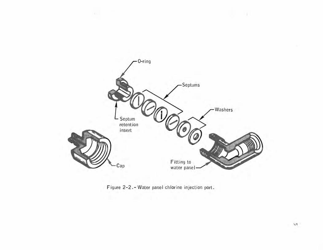
Minor leakage was noted from the chlorination injection port when the cap was removed to perform the prelaunch water chlorination. The cap was reinstalled and the leak ceased. A leak of approximately 1 quart in 20 minutes also was noted at the chlorine injection port as the crew removed the injection port cap for the third injection at about 61 hours. The crew tightened the port septum retention insert (fig. 2-2) and satisfactorily stopped the leakage. Leakage recurred at about 204 1/2 hours and was corrected.
As the cap is removed, the septum retention insert can back out of the water panel fitting because of the low torque values (5 in-lb maximum) used to squeeze the septums and washers into the fitting. Postflight inspection and dimensional checks of the injection port assembly will be made to determine the reason for loosening of the insert. The .use of a spacer and a higher torque value is being evaluated for use on future systems.
This anomaly is open.
2.3 SERVICE PROPULSION SYSTEM THRUST LIGHT ON ENTRY MONITOR SYSTEM
The service propulsion system thrust light located on the entry monitor system panel was illuminated shortly after transposition and docking.
A test firing performed at 28:40:30 indicated a short on the ground side of the service propulsion system pilot valve solenoids. The short was further isolated to the system A delta-V thrust switch which was found to be intermittently shorted to ground (fig. 2-3).
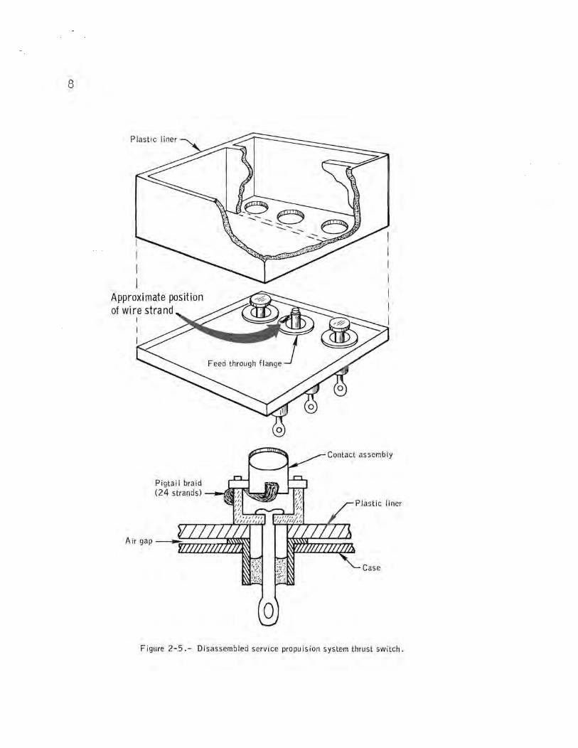
The delta-V thrust switch (fig. 2-4) was shorted to ground both before and after removal of panel 1 from the command module during postflight testing. The short-to-ground ceased, however, after a change in panel position. The switch was then removed from the panel and X-rayed. The X-rays showed a wire strand extending from the braid strap which was thought to have caused the grounding problem. After switch dissection, an internal inspection verified that a strand extended from the braid strap; however, it did not appear to be long enough to cause a ground at any point within the switch (fig. 2-4). The bracket assemblies (pivot brackets, pigtail braids, and movable contacts) and the plastic liner were removed from the switch. Microscopic examination revealed that a wire strand (approximately 0.060 inch long) was present on the flange on terminal 2 (fig. 2-5). The strand appeared to be attached, but was later moved quite easily.
insert
Cap Fitting to water panel
Figure 2-2.- Water panel chlorine injection port.
\Jl

28V dc
28V dc
Entry monitor system
Service propu Is ion system light
t::.V thrust A To automatic sWit~h control t---. --....J To telemetry
Engine valves Norm~
,'I~. :r~:~dto
To B thrust system
sWitch -=.
Figure 2-3.- Service propulsion system thrust light circuitry.
0\

7
Figure 2-4.- Service propulsion system delta-V thrust switch . .
8
Plastic l iner
Approximate position of wire strand
I I I
Pigtail braid (24 strands)
Contact assembly
Case
Figure 2-5. - Disassembled service propu Is ion system thrust switch.
9
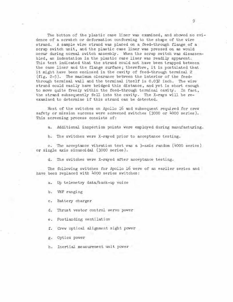
The bottom of the plastic case liner was examined, and showed no evidence of a scratch or deformation conforming to the shape of the wire strand. A sample wire strand was placed on a feed-through flange of a scrap switch unit, anc;l the plasti c case liner was pressed on as would occur during normal switch assembly. When the scrap switch was disassembled, an indentation in the plastic case liner was readily apparent. This test indicated that the strand could not have been trapped between the case liner and the flange surface; therefore, it is postulated that it might have been enclosed in the cavity of feed-through terminal 2 (fig. 2-5). The maximum clearance between the interior of the feedthrough terminal wall and the terminal itself is 0.032 inch. The wire strand could easily have bridged this distance, and yet is short enough to move ~uite freely within the feed-through terminal cavity. In fact, the strand subse~uently fell into the cavity. The X-rays will be reexamined to determine if this strand can be detected.
Most of the switches on Apollo 16 and subse~uent re~uired for crew safety or mission success were screened switches (3000 or 4000 series). This screening process consists of:
a. Additional inspection points were employed during manufacturing.
b. The switches were X-rayed prior to acceptance testing.
c. The acceptance vibration test was a 3-axis random (4000 series) or single axis sinusoi dal (3000 series).
d. The switches were X-rayed after acceptance testing.
The following switches for Apollo 16 were of an earlier series and have been replaced with 4000 series switches:
a. Up telemetry data/back-up voice
b. VHF ranging
c. Battery charger
d. Thrust vestor control servo power
e. Postlanding ventilation
f. Crew optical alignment sight power
g. Optics power
h. Inertial measurement unit power

10
i. Rendezvous radar transponder power
Switches for crew safety and mission success for Apollo 17 which are not screened switches will also be replaced.
In addition, two science utility power switches are to be disabled and stowed, and two circuit breakers are to be added to provide series protection for the command and service module/lunar module final separation function.
This anomaly is open.
2.4 INTEGRAL LIGHTING CIRCUIT BREAKER OPENED
The ac bus 2 and the dc bus B under-voltage alarms occurred and subse~uently the integral lighting circuit breaker opened.
A short circuit sufficient to cause the circuit breaker to open would also cause the alarms. As a result of the problem, the display keyboard lights, entry monitor system scroll lighting, and various other backlighting were not used for the remainder of the mission.
Investigation of the impedance of each circuit controlled by circuit breaker 33 uncovered a circuit into the electroluminescent lighting of the mission timer on panel 306 which read lower than normal (400 ohms as compared to a normal value in the megohm range). With a l-ampere fuse in the circuit and all other circuits except the panel 306 mission timer disconnected, the fuse would blow. However, with all other circuits to ', this fuse connected, except the mission timer on panel 306, the l-ampere fuse would not blow. The timer has been removed or failure analysis.
This anomaly is open.
2.5 BATTERY RELAY BUS READ 13.66 VOLTS DC
The battery relay bus measurement read 13.66 volts dc at approximately 81:19 (the reading should have been 32.0 volts dc). When the crew verified the position of the selector knob of the systems test meter switch, it was not exactly aligned to the battery relay bus position. The switch was then rotated to a different position and 'back to the battery relay bus pos i tion. The meter and corresponding telemetry measure~ents indicated properly thereafter.

11
It was believed that bridging of the adjacent contacts (fig. 2-6) would be the most likely cause of the anomaly. Postflight testing has revealed, however, that bridging of contacts could not reproduce the problem. Analysis indicates that a short of approximately 2.8 kilohms from the battery relay bus contact (fig. 2-6) of the switch to ground will reproduce the reading observed in flight.
The panel containing the systems test meter was removed from the spacecraft and all positions were checked for impedance to ground and to adj acent pins. No abnormal conditions were found. The panel will be installed in the spacecraft and the system tested with the signal condi tioning equipment in the circuit. Subsequently, theswi tch will be removed for teardown inspection if no abnormalities are found.
This anomaly is open.
2 .6 MASS SPECTROMETER BOOM TALKBACK
INDICATED HALF-BARBERPOLE ON RETRACT
On five different occasions, the mass spectrometer boom did not fully retract. Temperature data indicate that the problem was preceded by cold soaking of the boom and/or experiment.
The following possible causes of the problem are being considered:
a. Interference between the rail support assembly and the spectrometer bearing assembly (fig. 2-7).
b. Binding in the floating rail.
c. Spectrometer cable low temperature stiffness or interference problems such as improper stacking, retraction limit switch push rod being blocked, and pinching of cable between bearings and the funnel (fig 2-8).
d. Interference of tie-down rod end.
e. Interference of limit switch actuating pin with housing (fig. 2-9).
f. Cover mechanism interference.
g. Step lock binding.
Tolerances in these areas are being studied. Also a visual inspection of the Apollo 16 deployment mechanism will be performed and critical clearances will be measured. In addition a thermal vacuum screening test

12
Battery relay bus (8) -----.... _
Oxidizer feedline ----....... temperature (A)
~~~,..---- Possible bridging
Suspecte ShO'.
(a) Cross section of one of nine wafers
5
6 o
o 4
6 o
Battery re lay bu s -o-... O----5;;;o~..J..(:)--~ Oxiderizer feedline-o o temperature A 4
Switch 1 Switch 2
(b) Systems test meter circuitry
Figure 2-6. - Systems test meter switch.
of contacts by incorrect pos itioning of selector knob
Systems test meter

Figure 2-7.- Mass spectrometer right-hand bearing, rail, and rail support. r' VJ

14
Front end of actuation pin that depresses the retraction limit switch push rod
Figure 2-8.- Mass spectrometer boom mechanism (spectrometer not installed).

15
Figure 2-9.- Mass spectrometer boom mechanism.

16
is planned to insure that the mechanism is within tolerance with expected temperatures and temperature gradients. This inspection and testing will require approximately 4 months to complete.
This anomaly is open.
2.7 POTABLE WATER TANK FAILURE TO REFILL
The potable water tank quantity began to decrease during meal preparation at approximately 277 hours and failed to refill for the remainder of the flight. The waste water tank continued to fill normally and, apparently, accepted fuel cell water for this period. A similar occurrence had been noted earlier, at 13 1/2 hours , when the potable tank quantity decreased, and the tank began to refill only after a waste water dump at 28 1/2 hours. This decrease had been attributed to a closed potable tank inlet valve until the crew verified in their debriefing that the valve had been open during this time. The amount of water drained from the tank verified that the tank instrumentation was reading correctly.
During a postflight fill operation, with water introduced at the hydrogen separator and the waste tank inlet valve closed, the potable and waste water tank filled (fig. 2-10). This shows that the suspect check valve in the waste tank dump leg (fig. 2-10) did not check. The path of least resistance with the check valve leaking would be to the tank with the lower quantity.
The valve will be removed from the spacecraft for further tests and teardown inspection to determine the cause of the malfunction.
This anomaly is open.
2 .8 MISSION TIMER STOPPED
The mission timer on panel 2 stopped at 124:47:37. It was reset for 124:59, but did not start. Later, all digits were reset to zero and the timer started counting. The proper time was set and the timer continued to operate properly for the remainder of the mission.
Postflight, the timer failure could not be dupli cated in the spacecraft. The timer has been removed from the spacecraft for failure analsis. This activity will take approximately 3 weeks.
This anomaly is open.

-c::==~~ To dump
From/to suit
Waste tank inlet valve
From fuel cell
Potable tank
heat exchanger --i::::()():E;'X ~::=!!IItr~~==::(~=======~=~~:::"\
To primary/secon- -dary evaporator
Waste tank
, Inlet nOll Ie
To food preparation and drinking water
Figure 2-10.- Water management system and failed check valve details.
17
18
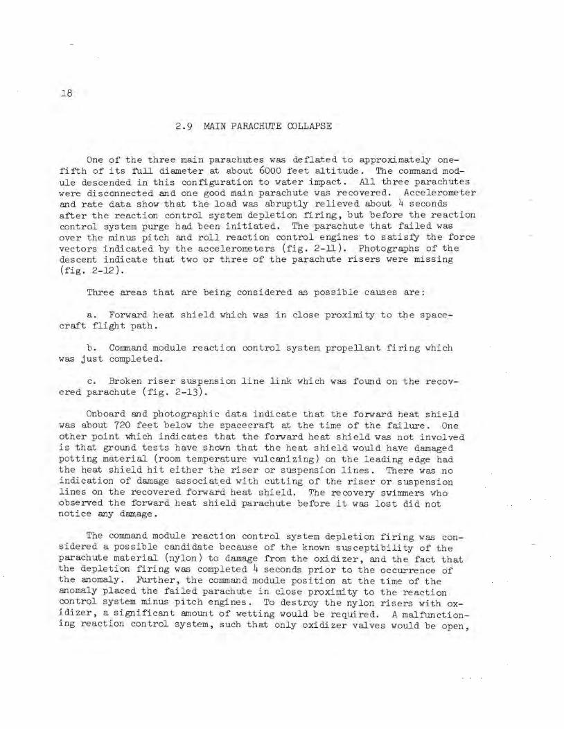
2.9 MAIN PARACHurE COLLAPSE
One of the three main parachutes was deflated to approximately onefifth of its full diameter at about 6000 feet altitude. The command module descended in this configuration to water impact. All three parachutes were disconnected and one good main parachute was recovered. Accelerometer and rate data show that the load was abruptly relieved about 4 seconds after the reaction control system depletion firing, but before the reaction control system purge had been initiated. The parachute that failed was over the minus pitch and roll reaction control engines to satisfy the force vectors indicated by the accelerometers (fig. 2-ll). Photographs of the descent indicate that two or three of the parachute risers were missing (fig. 2-12).
Three areas that are being considered as possible causes are:
a. Forward heat shield which was in close proximity to the spacecraft flight path.
b; Command module reaction control system propellant firing which was just completed.
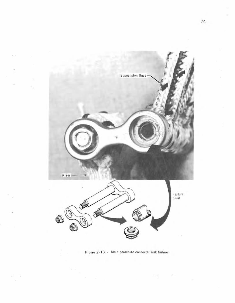
c. Broken riser suspension line link which was found on the recovered parachute (fig. 2-13).
Onboard and photographic data indi cate that the forward heat shield was about 720 feet below the spacecraft at the time of the failure. One other point which indicates that the forward heat shield was not involved is that ground tests have shown that the heat shield would have damaged potting material (room temperature vulcani zing) on the leading edge had the heat shield hit either the riser or suspension lines. There was no indication of damage associated with cutting of the riser or suspension lines on the recovered forward heat shield. The recovery swimmers who observed the forward heat shield parachute before it was lost did not notice any damage.
The command module reaction control system depletion firing was considered a possible candidate because of the known suscepti bili ty of the parachute material (nylon) to damage from the oxi di zer, and the fact that the depletion firing was completed 4 seconds prior to the occurrence of the anomaly. Further, the command module position at the time of the anomaly placed the failed parachute in close proximity to the reaction control system minus pitch engines. To destroy the nylon risers with oxidizer, a significant amount of wetting would be required. A malfunctioning reaction control system, such that only oxidizer valves would be open,

350 335 350
Reaction 320 335 control 305 320 system m Reaction 305 helium 275
control system 290
manifold 2 260
~t 4000 helium 275 pressure, 245 manifold 1 260 psia
230 pressure, Pyrotechnic Reaction 3000 245 bus A voltage, 35
215 I psia control 230 volts dc system
200 215 tank 2 2000 200 30 helium
pressure, psia 1000
0
Scale ref~rence line
+2
+1 Z-axis acceleration, 0 9
-I
-2
Reaction control system tank 1 h~lium
pressure, psia
Pitch rate, de9/sec
First visual sighting 295:08:05,
I +5.0
+2.5
o
-2.5
+5.0 -5.0
Yaw rate, deg/sec
+2.5
o
-2. 5
-5.0 +5.0
+2.5 -
Roll rate, 0 deg/sec
-2.5
-5.0
+2
+1 Y-axis acceleration, 0 g
4000 -I +10
-2 +8 3000 +6 X-axis
2000 acceleration, +4 g +2
1000 0 -2
0
295:08:00
19
Last frame on onboard Reaction controt system purge start 2~5:09:21. 8
r Reaction control system
camera film 295:08:43\ depletion firing [spacecraft emerged from (First colored cloud Reaction control system completed 2'15:09: 10\ cloudS 295:0~:12 295:09:24 depletion firing start rspacecraft obscured by ~First sighting of /second colored cloud
Falling object sighted below damage 295:0Y:15 295:09:28 295:08:22, clouds 295:08:47 the spacecraft 295:09:08
". __ . __ '_' "_L_" ~' .. :,::_:.L _·...:':.::.:..:,;·...:;..·,::: ... : .. ,_· .. '~'~' _ _ ':::_' ~:_. " -_L~~'_'_'_' ,
Yaw rate-.............
~~
R a II ra t e """'"""'-
Z-ax is accelerationJ r Reaction control system helium : ani fOld 2 pressure
- '-Reaction cont rol system Y-ax is acceleration -............ helium manifold 1 pressure
~+=~::~~::::q:====::;==========~====~==~===:==========================~~~ --------~-----Fyrotecllnic bus A vo llaye
II I I I I I I I 08:10 08:20 08:30 08:40 08:45 08:50 08:55
Reaction control system tank 2 eliu m press ure
A -axis accelerat ion """"'"
1111111111
295:09:00 09:05
Time, hr:min:sec
~Readion contro l s stem tan K 111~li um pressu re
I I I I I I I I. I 09:10 09:15 09:20
/ I
I I I I I I I I
09:25 09:30 09:35
Figure 2-11. - Sequence of events during descent on the main parachutes.
I I 09:40

20
Figure 2-12.- Parachute riser damage noted during final descent.
Suspension lines
Ris er---~
Figure 2-13. - Main parachute connector link fai lure.
F ai lure point
21

22
could have caused.the failure. However, postflight tests on the command module and the flight data at the time of the anomaly both indicate that no abnormal operation occurred.
The failed link on the recovered parachute implies the possibility of a similar occurrence on the failed parachute. This satisfies the flight data and the visual and photographic data. However, two or three links would have had to separate simultaneously; this item is undergoing further investigation.
Possibilities for the link failure include hydrogen embrittlement, stress corrosion, material defects, manufacturing defects, or assembly problems.
Structural testing and metallurgical examination on the recovered links, and links of different lots, indicate that the hydrogen embrittlement concern was not evident on the flown links. Additionally, all test indications show that saltwater exposure did not induce the cracks, although rusting would be rapid if cracks existed at the time the links were exposed to saltwater. The results indicate the broken link flaw probably occurred prior to saltwater immersion for a reason that is not currently understood.
A summary of the analysis completed at this time shows:
a. The analysis rules out the forward heat shield as being the cause; however, consideration is being given to adding an additional parachute to the forward heat shield to assure that it does not land prior to the command module, thUs avoiding any chance of recontact.
b. The reaction control system is still suspected, but the mechanism has not been established. However, measures are being taken to inhibit the minus pitch engines and possibly one of each pair of opposing roll engines during the reaction control system depletion firing, thus reducing the potential damage to the parachute risers resulting from heat or oxidizer.
c. The links are still suspected.
d. Other possible investigations and analyses are still being considered to determine what caused the parachute failure.
A complete discussion of all analyses and tests will be provided in a separate anomaly report when the investigation is completed.
This anomaly is open.

23
2.10 DATA TAPE DETERIORATION
At about 240 hours, after over 100 tape dumps had been completed, the ground was unable to synchronize on the data contained on about the first 20 feet of tape. To alleviate the problem, the tape was not fully rewound on subsequent tape rewinds. .
A complete acceptance test, including a flutter spectrum test, will be performed on the recorder. The analysis of the tape will include developing portions with suspended metal oXides and observing the recorded magnetic signals. In addition, wave-train playbacks of both the 51.2 and 64 kilobit data systems will be analyzed.
This anomaly is open.
2.11 SECONDS WINDOW ON DIGITAL EVENT TIMER OBSCURED
The seconds wind,ow on the digital event timer became obscured during the mission. The crew stated that the window appeared as if a powder had been deposited on the inside.
The material deposits are still present on the window and the timer has been removed for analysis. This will include a chemical analysis to determine the source of the material. Testing should be completed in about 1 week.
This anomaly is open.
2.12 CREW RESTRAINT HARNESS CAME APART
The restraint harness on the right side of both the center and right crew couches came apart during lunar orbit. The assemblies had become unscrewed, but the crew was able to retrieve all the parts except one cap
.and reassemble the harnesses satisfactorily for landing. The mating plug for the missing cap was held in place with tape.
The plug-and-cap assembly (fig. 2-14), which is part of the universal assembly that attaches the restraint harness to the couch seatp8Jl, separated. (There are a total of six plug-and-cap assemblies on the crew

Figure 2-1 , _ 4._ Crew
restraint h arness co
nnector

25
couch, two per man.) The plug component (bolt) has a nylon insert in the threaded portion that acts as a locking device. Fore and aft rotation of the adjuster link can cause the plug-and-cap assembly to unscrew from each other. The locking insert appears to have marginal engagement.
Staking or use of a thread locking sealant is being evaluated to prevent the problem on future missions.
This anomaly is open.
2.13 LOOSE OBJECT IN CABIN FANS
During portions of the flight when the cabin fans (fig. 2-15) were activated, noises were heard which sounded like an object striking the blades, and lodging of the object within the fan housing even stopped the fan. Cycling the fans several times allowed the fan to run again.
Inspection and testing is scheduled to locate the problems.
This anomaly is open.
2.14 EXCESS GAS IN POTABLE WATER
The crew noted gas in the potable water and that the ~uantity would increase with heavy usage, as at the end of an eating period. However, according to the Commander, the overall gas ~uantity was much improved over that encountered on Apollo 9 and the problem was not nearly as severe. Also, some difficulty was reported in using the gas separator cartridge assembly on the food preparation unit, and the use of the assembly was limited almost entirely to the water gun.
Postflight testing will include a ~uali tati ve performance evaluation of the in-line hydrogen separator and a predelivery acceptance test and inspection of the gas separator cartridge assembly. Two water samples, taken during the mission for determination of nickel content, have been examined. One contained no gas at sea-level pressure. A small ~uantity of gas in the second sample was analyzed and found to be air, believed to have diffused into the bag after the mission.
This anomaly is open.

Aluminum-plate diverter
Shroud
Air flow
Figure 2-15. - Cabin fan installation.
·c;.;}{'
=- -J.-=-\ ~,
---j
I\) 0\

21
2.15 SCANNING TELESCOPE VISIBILITY
The crew reported that excessive attenuation of light through the scanning telescope existed throughout the flight. The telescope was adequate to perform landmark tracking while in lunar orbit, but the crew was unable to identify constellations, even though large numbers of stars could be seen by looking out the spacecraft window. The crew believed that the condition would have prevented performing a platform alignment, had the need arisen.
Visual observations through the telescope have been made at the spacecraft manufacturer's facility, and no degradation could be observed. A luminescent transmittance test has been performed on the telescope before removal from the spacecraft. Preliminary analysis of the test results indicates a decrease in luminescent transmittance. However, a decrease would be expected because of the contamination from sea water. In spite of the contamination, the value measured in this test was only slightly below the minimum acceptance level. The optical unit and all eyepieces will be returned to the vendor and another luminescent transmittance test will be performed under laborat ory conditions. The unit will then be disassembled and examined.
This anomaly is open.
2.16 GYRO DISPLAY COUPLER ROLL ALIGNMENT
The crew reported that the roll axis did not align properly when the gyro display alignment pushbutton was pressed. The roll axis error was not nulled, whereas, the pitch and yaw axes were. Only by depressing the align pushbutton for progressively longer periods, and eventually, by moving the roll-axis thumbwheel, could the roll error be nulled.
For normal operation during alignment, resolvers in the gyro display coupler electronics are compared to resolvers, one for each axis, on the thumbwheels used to set desired attitude. The difference is an error signal. The error is displayed on the attitude error needles, and the signal is used to drive the resolvers to match the attitude set on the thumbwheels.
The electronics that could cause the problem will be removed from the spacecraft for functional tests. Further tests and analyses will be dependent upon functional test results.
This anomaly is open.

28
2.17 UNABLE TO OPEN BATTERY CHARGER -
MAIN A CIRCUIT BREAKER
The battery charger - main A circuit breaker could not be opened manually during the postflight testing.
A green, corrosion-like area at the interface of the indicator sleeve and motmting bushing was evident.
Inspection of the circuit breaker and chemical analysis of the corrosion are in progress.
This anomaly is open.
2.18 PIVOT PIN FAILURE ON MAIN OXYGEN
REGULATOR SHUTOFF VALVE
The toggle arm pivot pin for the side-A shutoff valve of the main oxygen regulator (fig. 2-16) was found sheared during the initial actuation from the open to the closed position during postflight testing.
With the pin failed, the shutoff valve is inoperative in the closed position, thus preventing oxygen flow to the regulator.
The failed pin will be analyzed with respect to the material, its fracture characteristics, and the design.
This anomaly is open.

Fa i led Pin .. OPEN
~~~~ If VALVE
(Closed position shown)
Figure 2-16.- Sheared pin on oxygen regulator shutoff valve.
29

30
3.0 LUNAR MODULE ANOMALIES
3.1 WATER/GLYCOL PUMP DIFFERENTIAL PRESSURE FLUCTUATIONS
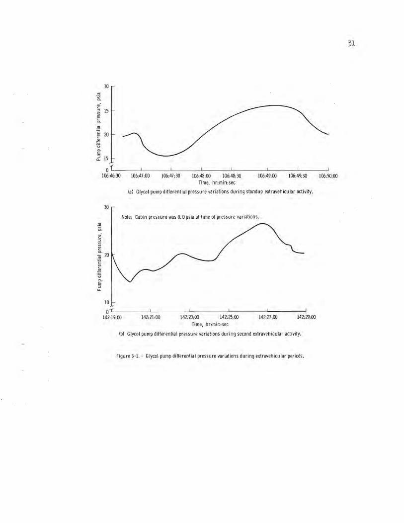
Variations were noted in the water/glycol pump differential pressure shortly after the cabiq depressurizations for the standup extravehicular activity and the second extravehicular activity. The variations were similar on both occasions. The pressure differential decreased from about 20 psid (normal) to about 15 psid, then increased to about 27 psid and returned to normal (fig. 3-1). The total time for the cycles took 3 minutes (standup extravehicular activity), and 10 minutes (second extravehicular activity). The pump discharge pressure remained relatively stable throughout both periods.
If pressure fluctuations had taken place in the heat transport system, the pump discharge pressure and pressure differential should both vary together. After the second fluctuation occurred, glycol pump 2 was selected, but the cycle was complete, and the pressure differential had already returned to normal. Therefore, all parameters were normal during pump 2 operation. The crew reselected pump 1 prior to egress for the second extravehicular activity, and it operated satisfactorily. Later, after docking, the pump was turned off momentarily and the pump discharge pressure readout was verified to be correct since it decreased to the accumulator pressure of 7.8 psia.
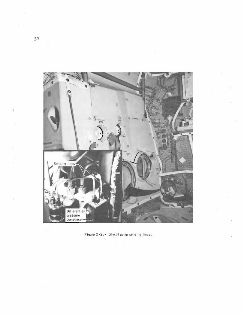
The lunar module cabin humidity was high at initial manning for descent because the command module cabin humidity was high. Furthermore, a water spill in the lunar module cabin after the first extravehicular activity again produced high humidity. Consequently, water would have condensed on the cold glycol lines and would have frozen and sublimed at the next cabin depressurization. There is no glycol flow in the 1/8-inch sense lines between the pump assembly and the pressure transducer (fig. 3-2). Analysis shows that as little as 0.01 inch of condensed moisture on the outside of these lines would freeze the fluid in the sense lines and cause the fluctuations in the indicated differential pressure, but would not affect system operation. Consequently, no corrective action is required.
This anomaly is closed.
31
30
0..
E 6: 15
01~------~ ____ ~ ______ ~ ______ ~ ______ ~ ______ ~ ____ ~ 106:46:30 106:47:00 106:47:30 106:48:00 106:48:30 106:49:00 106:49:30 106:50:00
Time, hr:min:sec
(a) Glycol pump differential pressure variations during standup extravehicular activity.
30
Note: Cabin pressure was 0.0 psia at time of pressure variations . . !!! ~
0.
~-:::J ~ ~
~ 0.
.!!! 20
C ~ ~ "0 0..
E :::J
"-
10
01' 142:19:00 142: 21:00 142:23:00 142:25:00 142:27:00 142:29:00
Time, hr:min:sec
(b) Glycol pump differential pressure variations during second extravehicular activity,
Figure 3-1. - Glycol pump differential pressure variations during extravehicular periods.
32
Figure 3-2.- Glycol pump sensing lines.

33
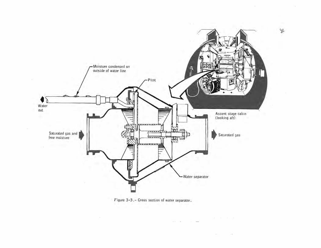
3.2 WATER SEPARATOR SPEED DECREASE
The speed of water separator 1 decreased to below 800 rpm and tripped the master alarm during the cabin depressurization for the standup extravehicular activity. Separator 2 was selected and operated properly at approximately 2400 rpm. After approximately 1 hour of separator 2 operation, separator 1 was reselected and performed satisfactorily throughout the remainder of the mission.
Cabin atmosphere is cooled and passed through one of the water separators (fig. 3-3) where condensed water is separated by centrifugal force and picked up by a pitot tube. The water is then piped from the pitot tube, through a check valve, to the water management system where it is used in the sublimator.
Cabin humidity was high before the standup extravehicular activity and, because the water was cold, the tubing between the water separator pitot tube and the water management system was cold. Under these conditions, water would condense on the outside of the tube, and when the cabin was depressurized for the standup extravehicular activity, the water on the outside of the line would boil and sublime, freezing the water in the line.
Analysis shows that as little as a O.Ol-inch film of water on the outside of the line would freeze the line at cabin depressurization. Freezing within the line would cause the separator to slow down and stall because of excessive water. Since separator 2 had not been in use, there was no water in its outlet line to freeze, and therefore, it operated successfully at startup. In any event, analysis and tests have shown that freezing of the line will not damage any spacecraft hardware. In addition, no cabin depressurization is planned for any future mission where th~ crew would be using the spacecraft water separators and where cabin humidity would be high. If such a depressurization is performed, the water separator line would probably again freeze. If this were to occur, however, the other separator would be used. Therefore, no corrective action is required.
This anomaly is closed.
Moisture condensed on outs i de of water line
.u lJ-~ Water out
Saturated gas and .. free moisture .,.
Figure 3-3.- Cross section of water separator.
t Saturated gas
w +=-

35
3.3 BROKEN WATER GUN/BACTERIA FILTER QUICK DISCONNECT
A water leak developed in the lunar module cabin shortly after crew ingress following the first extravehicular activity. The leakage occurred at the quick disconnect between the bacteria filter and the water gun (fig. 3-4). The leakage was stopped by removing the filter. The plastic (Delrin) portion of the disconnect had broken in half, thus causing the leakage.
When the water gun/bacteria filter combination is properly stowed, the gun is held in a U-shaped boot, and both the gun and filter are held in place with straps with the hose protruding above the liquid cooling assembly. Bending the hose can easily exceed the force required to break the quick disconnect between the bacteria filter and the water gun if the filter is not strapped down. A test showed that a torque of 204.6 inchpounds caused a similar quick disconnect to break in half. Based on the torque value of 204.6 inch-pounds, a force of approximately 27 pounds applied at the hose quick disconnect interface would break the disconnect between the filter and the water gun.
A possible redesign of the quick disconnect to eliminate the Delrin, and, thus, preclude a recurrence of the problem, is being investigated.
This anomaly is open.
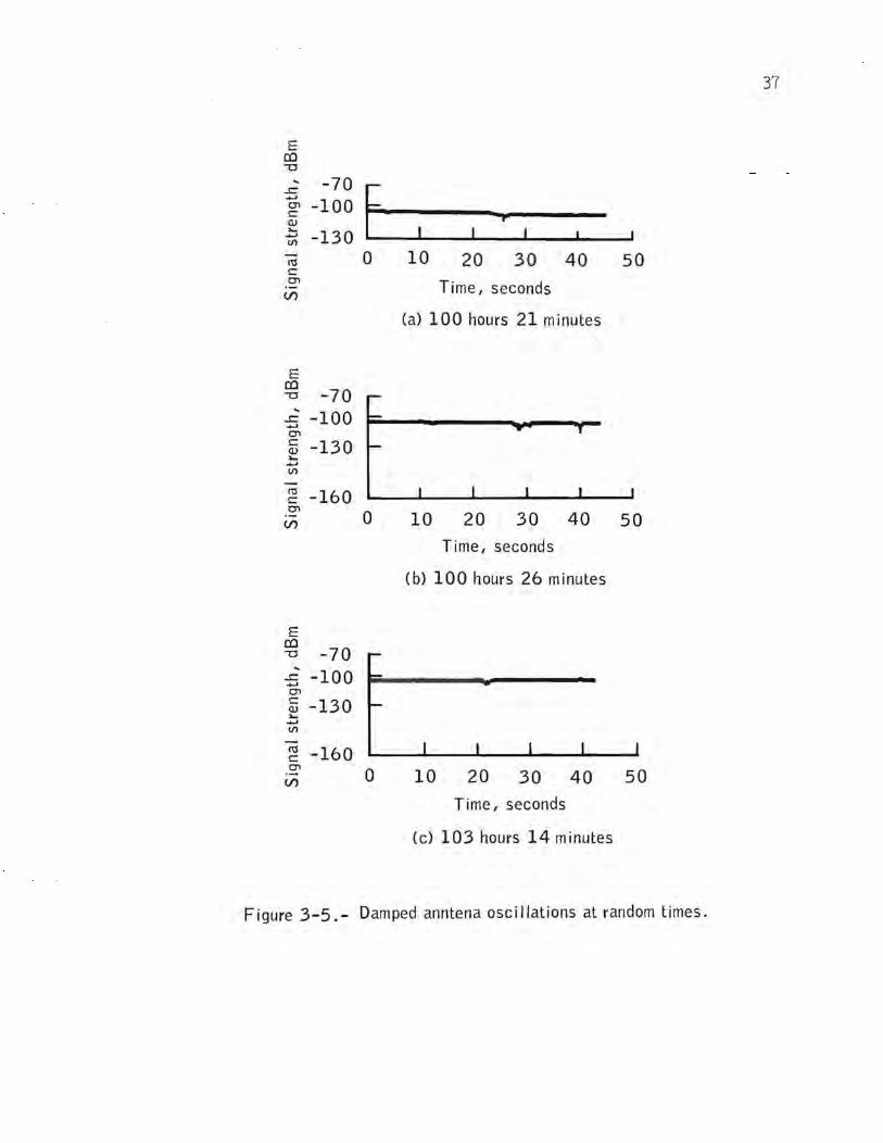
3.4 INTERMITTENT STEERABLE ANTENNA OPERATION
Small oscillations occurred at random while the steerable antenna was in the auto-track mode of operation. With the following exceptions, the oscillations were small and damped out without losing auto-track capability (fig. 3-5) .At the following three times the oscillations became divergent as shown in figure 3-6.
a. 100:26 (revolution 12): This divergence occurred prior to separation and was not caused by vehicle blockage or reflections from the command and service module structure.
b. 100:41 (revolution 12): The lunar module maneuver performed approximately 2 minutes after separation caused the antenna to track into vehicle blockage which resulted in the antenna oscillation and loss of lock.

Figure 3-4.- Water gun/bacteria filter.
Plastic portion of quick disconnect broken
37
E [!) -0 .. -70 ...s:: [ ......
-100 0"1 c P Q) :...
-130 ...... V)
I'U 0 10 20 30 40 50 c 0"1 Time I seconds (/)
(a) 100 hours 21 minutes
E [!)
-70 -0 .. -100 ...s:: ......
0"1 c -130 Q) :... ...... V)
I'U -160 c 0"1
(/) 0 10 20 30 40 50
Time I seconds
(b) 100 hours 26 minutes
E [!) -0 -70 ..
-100 ...s:: ...... 0"1 c -130 Q) :... ...... V)
I'U -160 c 0"1
0 10 20 (/) 30 40 50
Time I seconds
(c) 103 hours 14 minutes
Figure 3-5.- Damped anntena oscillations at random times.

E co
-70 ~ -100 ~
O'l s::: (l) :... ~
til
-130
~ -160 O'l I~ __ -L ____ ~I __ ~I~ __ ~I ____ ~ __ ~I _____ I
(j)
E co --0 -70 ~ -100 ~
O'l
~ -130 :... ~
til
~ -160 O'l
E co --0 ~ -70
-5 -100 O'l s::: ~ -130 ~
til
m ~ -160
(j)
o 10 20 30 40 50 60 70 Time I seconds
a. Oscillations at 100 hours 26 minutes.
o 10 20 30 40 50 60 70
Time I seconds b. Oscillations at 100 hours 41 minutes.
I
o 10 20 30 40 50 60 70
Time I seconds
c. Oscillations at 104 hours 07 minutes.
Figure 3-6. - Received signal strength plots assoc iated with
divergent antenna oscillations.

39
c. 104:07 (revolution 14): Earth look angles for this time period indicate that the antenna was clear of any vehicle blockage. However, since this divergence occurred just after acquisition of signal, the lunar module was still close to the lunar horizon, and the problem may have been caused by multipath reflections from the lunar surface.
Both the small oscillations which damped out and those which became divergent indicated characteristics identical to the conditions experienced on Apollo 14 (fig. 3-7). One of the prime candidates considered after Apollo 14 as a possible cause was incidental amplitude modulation on the uplink signal. A monitor capable of detecting very small amounts of incidental amplitude modulation was installed at the Madrid Manned Space Flight Network site for Apollo 15. The data from this monitor have indicated that no amplitude modulation at the frequencies critical to antenna stability existed on the uplink during the problem times. Consequently, incidental amplitude modulation has been eliminated as a possible cause of the antenna oscillations, and the problem must be in the spacecraft .
The conditions existing during the oscillations cannot be correlated to any specific event or change in spacecraft status. Also, since similar problems have existed on almost every Apollo flight that has utilized the steerable antenna, it appears that there is a condition of tracking instability inherent in the antenna design. Proposed modifications to the antenna to decrease its susceptibility to oscillations were studied during the Apollo 14 investigation. All of the proposed methods were too extensive or resulted in insignificant improvement to warrant consideration at this point in the Apollo program.
A thermal test is being considered for the lunar module steerable antenna because of the existence of a thermal problem associated with the command and service modules high-gain antenna which results in noise being introduced into the tracking loop by the antenna gimbals. This test would attempt to duplicate under thermal stress the oscillations experienced during flight.
This anomaly is open.
3.5 DESCENT ENGINE CONTROL ASSEMBLY CIRCUIT BREAKER OPEN
The descent engine control assembly circuit breaker was found open during an engine throttle check after lunar module separation from the command and service modules. The circuit breaker was then closed and the check was successfully performed.

40
E co -0
~
-100 t ....c ...... : I~ C1 c (I) >-
-120 ...... VI -140 ro 0 2 4 6 8 c C1
(/') Time, seconds
Apollo 14
E co -0
-100 ~
....c ...... -120 C1
c (I) ,...
-140 ...... VI
ro -160 c
C1
(/') 0 2 4 6 8 Time, seconds
Apollo 15
Figure 3-7.- Apollo 14 and 15 antenna oscillation characteristics.

41
The crew stated that they may have left the circuit breaker open. If they did not, a short to ground of sufficient magnitude to open the breaker (fig. 3-8) would have to have occurred. To open the 20-ampere breaker, loads of 30 amperes for 1 minute up to 200 amperes for 1 second are required.
Available data were reviewed for current surges high enough to trip the breaker but none were found. (No data are available for the period when the lunar module was behind the moon.)
A hard short between the circuit breaker and any of its loads would draw between 500 and 1800 amperes, limited by wiring resistance. A current this large would have tripped the dc bus under-voltage alarm and master alarm; however, no alarms occurred. Therefore, the most probable cause of the circuit breaker being open when reported was that the crew inadvertently left it open.
This anomaly is closed.
3.6 ABORT GUIDANCE SYSTEM WARNING
An abort guidance system warning and master alarm occurred at 171:45 (right after insertion into lunar orbit) and at 180:55 (at acquisition of signal prior to lunar module deorbit). The first one was reset by the crew; the second persisted until lunar impact. Performance of the abort guidance system appeared normal before, during, and after the time of the alarms .
Anyone of four conditions in the abort guidance system can cause the system warning light to illuminate. They are:
a. 28 volts dc ± 2.8 volts (resets automatically)
b. 12 volts dc ± 1.2 volts (resets automatically)
~. 400 Hz ± 15 Hz (resets automatically)
d. Test-mode fail input from the computer (reset by placing the oxygen/water quantity monitor switch to the C/W RESET position) .
The conditions for generating a test mode fail signal are as follows; however, none of these conditions was indicated in any of the computer data.

42
r---------l Stabi lization/ control I Descent eng ine descent engine control : control assembly
J:1assemb~~er~~~~~~~~~:~~~~ ____ ~s amperes
Commander's bus (+28V dc)
To instrumentation signal conditioner circu it breaker
Note: Shaded area indicates the portion of the circuit where short must have existed.
r-I I Buffer I I I I
: Signal conditioner : I electronics assemblYI
I I L _________ J
r-----------..., I . I
lK6 I
~ ...... ;r ! I I : Stabi I ization and contro I : I assembly no. 3 I I I L __________ -.J
Figure 3-8. - Descent engine control assembly circu it breaker loads.
a. Computer restart: A restart would cause internal status indicators to be reset and telemetry quantity "Vdx" to be set to a prestored constant (minus 8000 ft/sec).
b. Computer self test: puter memory and logtc tests. status bit.
Computer routines perform sum checks of comFailure of these would set a self-test fail
c. Program timing: If the computer program is executing any instruction (except a "delay" instruction) at the same time that a 20 millisecond timing pulse is generated, a test-mode fail will be generated. Computer routines running at the time of the warning have a worst-case execution time of 18.425 milliseconds of the allowable 20 milliseconds; therefore, a timing problem should not have occurred.
After the abort guidance system warning at insertion, the crew read out the contents of the computer self test address 412. There were no indications of a test-mode fail. The crew did not, however, reload all ze~ roes into address 412. Reloading all zeroes is required in order to reset a flip-flop (fig. 3-9) in the computer output circuit of the caution and warning system. Consequently, a subsequent test-mode fail would not have caused an abort guidance system warning. The fact that a second abort guidance system warning did occur restricts the location of the failure to the output circuit of the computer, the interface between the computer and the caution and warning system, or the caution and warning circuitry.
Analysis to date has been to verify guidance system performance after the time of the warnings. All preflight test data pertaining to abort guidance system warning limits have been reviewed. Circuit analysis is being performed to establish component failures that could cause the observed warnings, and all interface wiring, connectors, and splices, are being reviewed.
This anomaly is open.
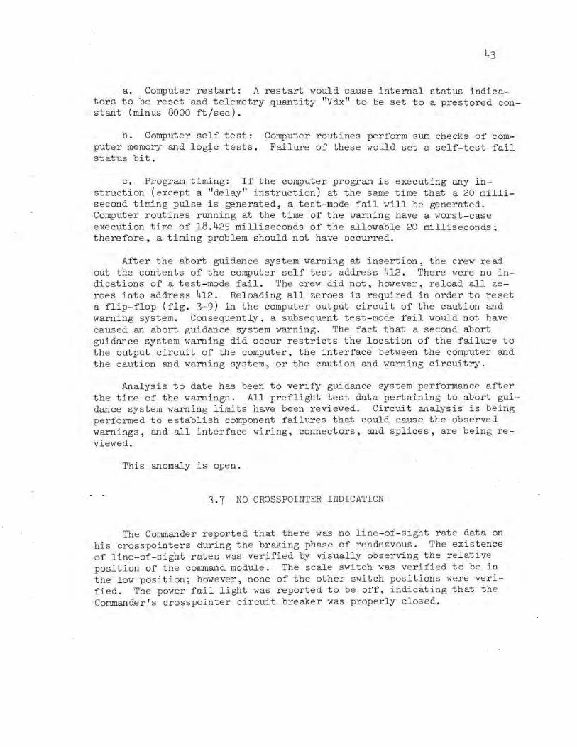
3.7 NO CROSSPOINTER INDICATION
The Commander reported that there was no line-of-sight rate data on his crosspointers during the braking phase of rendezvous. The existence of line-of-sight rates was verified by visually observing the relative position of the command module. The scale switch was verified to be in the low position; however, none of the other switch positions were verified. The power fail light was reported to be off, indicating that the Commander's crosspointer circuit breaker was properly closed.

Off
switch
L ___ _
Buffer Warning
inhibit
-----------------l Display lighting ,.....-t-- To master alarm power +5V dc........... I I
12V dc I Other abort guidance 28V dc system warning signals 400 Hz
I I I
':'
Abort guidance I system warning I light I
I ",,,.itt'"' 0,,,,"/ • .t" switch OO.po","1 0 ,","tily .'"it~
I I I I
L- _ i--
I I I I I I I I I I I I I I I I I
':'
L ___ _
Reset bus
Caution and warning system I --------------------~
Abort guidance computer
512K PPS
----------------Figure 3-9.- Abort guidance system test mode fail circuitry.
- ------------l
Note: Shaded area indicates type of failure which could have occurred in that area.
Set by computer restart; or computer s elf test fai I; or
I .. program timing fai I
Reset by loading all zeros in register 412
I I I I I I I I I I I I I I I I I
_____________ J
+:+:-

The rate error monitor switch is used to select either rendezvous radar data or data selected by the mode select switch for display. The mode select switch selects velocities from either the primary guidance system, the abort guidance system, or the landing radar for display. No telemetry data are available on the rate error moni tor switch and the mode select switch, and the Commander reported that he did not look at the flight director attitude indicator error needles.
There are five possible causes that meet the conditions reported, none of which can cause the total loss of radar antenna rate and position data display (fig. 3-10).
a. If the rate error monitor switch was in the LDG RDR/CMPTR position, the mode select switch would have to be in the AGS position to display any data. Lateral veloci ty from the abort guidance system, not antenna rate data, would be displayed. At this time, lateral velocity is expected to be near zero.
b. If the rate error monitor switch had contamination which shorted two contacts, it would have the same effect on the crosspointers as condi tion (a). The switch in this lunar module was X-rayed and screened but no contaminant was found. It should be pointed out that present screening and X-ray techni~ues might not detect a single wire strand between two contacts.
c. A wiring short to 28 volts dc on the rate error monitor switch relay would have the same effect as condition (a).
d. The signal return lead from the Commander's meter in panel 1 is routed to panel 2 where it is spliced to the signal return from the Lunar Module Pilot's meter and routed to the rendezvous radar. An open in the return line would cause loss of rate data to one or both meters, depending where the open occurred.
e. An open wire in the rendezvous radar electronics assembly which connects 15 volts ac at 400 Hz to two velocity filters (one each for shaft and trunnion rate) for display information.
Ade~uate redundancy is built into the antenna display circuits. Even an open in the return line to the rendezvous radar does not mean loss of all rate data. Position data can still be displayed on the flight director attitude indicator error needles, from whi ch rate data could be dequced.
More than likely, the failure was caused by an open in the ground return wire. Ground tests and checkout may not show this type of failure. If the open is temperature sensitive, a complete vehicle test involving vacuum, temperature, and temperature gradients would be re~uired to insure that failures of this type would not occur in the flight environment.

Commander Rate/ error 28V dc crosspointer monitor switch
JF,rcult breaker ...-J.-.. ~ Rendezvous
o Possi b le {!.~ ::::~ng short circuit· ·· ···· computer
I I
From I Cross pOinter I scale switch mode {primary gui
se lect land ing rada sw itch and lateral
all~~ u, } J +~ High r forward
'elocities t.
Rendez vous radar} shaft rate
Rendezvous radar} trunnion rate
Rendezvous radar} signal return
J
r J
r J
r J
c
'.0--0.. i\..
I I Low I I
• I I "High
I.f"l--(). I
~ I ~Low I
+: I I I .1 I
t -a,\ An open I
loss of both crosspointers
Shaft
rate
~ Trunnion rate
.:::
Shaft return
Trunnion return
Figure 3-10. - Simplified schematic of cross pointer circuits.
25-
20-
lS-
10-
5-
0-
S-
10-
lS-
20-
2S -
lS 10 5 6 5 1'0 l'S
.t:(J'\
This type testing is not practical at the vehicle level. consequently. no corrective is planned.
This anomaly is closed.
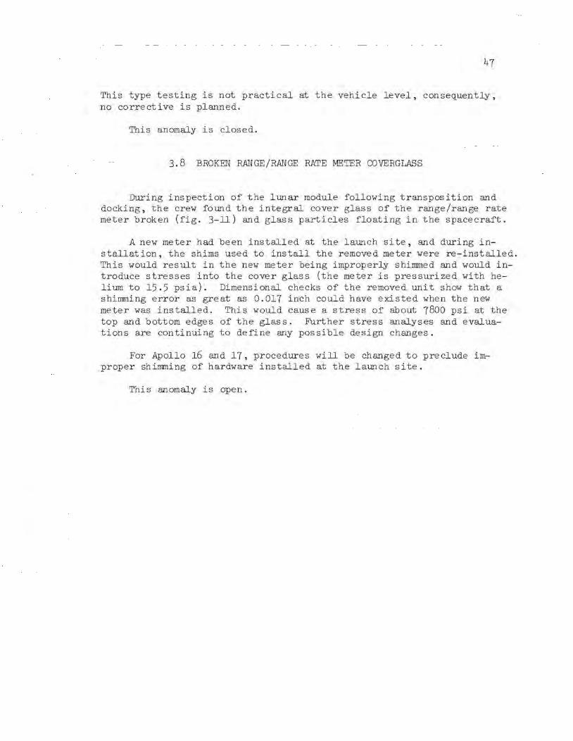
3.8 BROKEN RANGE/RANGE RATE METER COVERGLASS
During inspection of the lunar module following transposition and docking. the crew found the integral cover glass of the range/range rate meter broken (fig. 3-11) and glass particles floating in the spacecraft.
A new meter had been installed at the launch site. and during installation. the shims used to install the removed meter were re-installed. This would result in the new meter being improperly shimmed and would introduce stresses into the cover glass (the meter is pressurized with helium to 15.5 psia). Dimensional checks of the removed unit show that a shimming error as great as 0.017 inch could have existed when the new meter was installed. This would cause a stress of about 7800 psi at the top and bottom edges of the glass. Further stress analyses and evaluations are continuing to define any possible design changes.
For Apollo 16 and 17. procedures will be changed to preclude imr proper shimming of hardware installed at the launch site.
This anomaly is open.

48
Figure 3-11.- Range/range rate meter mounting .

49
4.0 SCIENTIFIC INSTRUMENT MODULE EXPERIMENT ANOMALIES
4.1 PANORAMIC CAMERA VELOCITY/ALTITUDE SENSOR ERRATIC
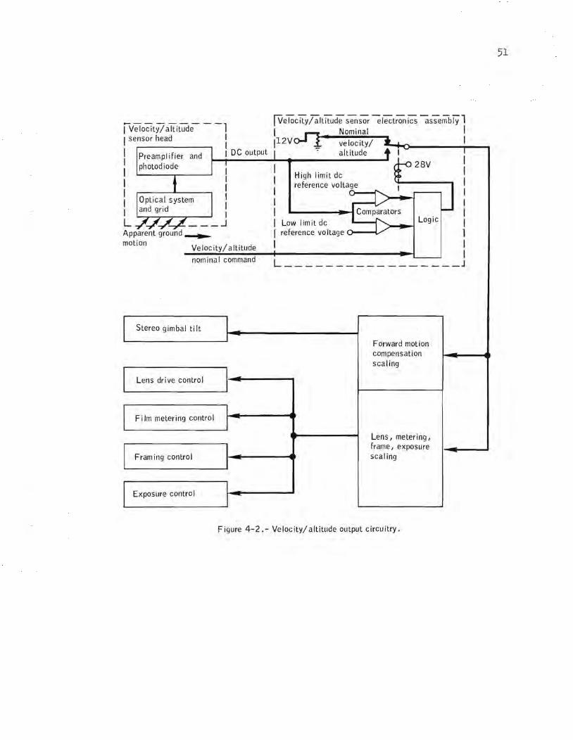
Telemetry received from the first panoramic camera pass on revolution 4 indicated the velocity/altitude sensor (fig. 4-1) was not operating correctly.
The velocity/altitude sensor measures the rate of travel of the spacecraft relative to the lunar surface. It also controls the cycling rate of the camera, the forward motion compensation, and the exposure, since the width of the exposure slit is dependent upon the scanning rate of the lens. The sensor is designed to operate in the range of 45 to 80 nautical miles altitude. If, at any time, the indicated velocity/altitude is out of this range, the sensor automatically resets to the nominal value of 60 nautical miles.
Telemetry indicates that the velocity/altitude sensor tended to operate properly for brief periods of time, but would drift off-scale high (saturate), and then reset to the nominal value corresponding to a 60-nautical-mile altitude. Evaluation of the velocity/altitude telemetry data indicates that approximately 75 percent of the photography should be of excellent Quality, with the remainder degraded to various degrees. Preliminary viewing of the developed film did not disclose gross degradation, but an extensive review using a microscope will be reQuired for a valid Quantitative assessment of overall picture Quality.
A circuit analysis of the velocity/altitude electronics (fig. 4-2) was performed in an attempt to isolate a component that may have been defective, but the results were negative. Breadboard testing is now in progress. In addition, tests were conducted in which an endless belt of lunar scene photography from Apollo 8 was passed in front of velocity/altitude sensors. Sensors from the prototype and Qualification units, and flight unit number 1 were used. By varying the illumination level, sensor performance somewhat similar to the Apollo 15 anomaly could be obtained. Although the anomalous performance during the mission occurred with lunar scenes of both high and low contrast and high and low illumination levels, the possibility of a basic error in the velocity/altitude sensing concept is not being discounted. Therefore, further simulations utilizing Apollo 15 panoramic camera pictures are to be performed.

50
Note: See figure 4-2 for assoc iated circuitry
Preampl ifier
Connector
S~~~~f;l.-f~- Photo diode
Lens and retic Ie
Hous ing
~===:$===~'-- Lens
Figure 4-1. - Veloc ity/ altitude sensor assembly.
!Ve!;;city/altitude sensor el~t~ics as-;embiYl I Nominal I 11 2V velocity/ I
-:- altitude
Iv;iocity/altitude --1 I sensor head :
I Preampl ifier and I DC output : photodiode 1-.,.1----.&.... ... ---------'
I I High limit dc
28V I I I I I I I I I
I reference voltage I I I I l L '.../- ___ ...1 Apparent ground ~
Low limit dc reference voltage 0--.....(/
motion V I . / I' d e oClty a tltu e
Logic -""~--l
I nominal command L _________________ J
Stereo gimbal ti It
Lens drive control
Film metering control
Fram ing control
Exposure contro I
Forward motion compensation scaling
Lens I metering I
frame I exposure scaling
Figure 4-2.- Velocity/altitude output circuitry.
51

52
A manual override of the velocity/altitude sensor on the remalnlng flight units is being considered. By utilizing a three-position switch, two preselected velocity/altitude ratios could be provided, as well as the automatic function.
This anomaly is open.
4.2 LOSS OF LASER ALTIMETER ALTITUDE DATA
The laser altimeter exhibited two anomalous conditions during the mission:
a. Altitude data became erratic after revolution 24 as the result of a decrease in the laser output power.
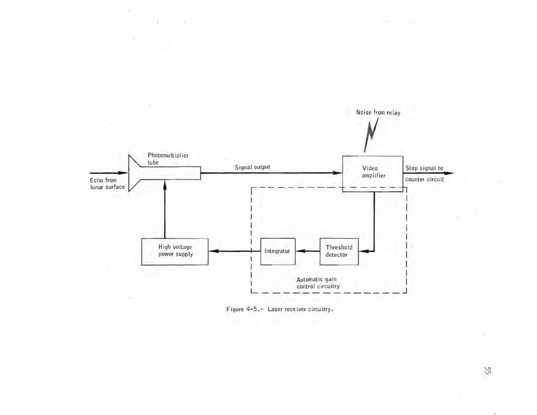
b. Starting on revolution 38, the photomultiplier tube highvoltage power supply was held in the idling (minimum-voltage level) mode until after the laser was fired, thereby causing the receiver to miss the return pulse from the lunar surface (fig. 4-3). No altitude data were obtained after this anomaly occurred.
The cause of the low output power anomaly has not been isolated. A review of the manufacturing records has established that the flight unit was the same as the Qualification unit with regard to parts, processes, and manufacturing methods. The possible effect of contamination on the output power is currently being investigate,d.
A relay which had been removed from a flight unit because it had exhibited an audible "buzz" was installed in the prototype altimeter
and the photomultiplier tube power supply anomaly was duplicated. The relay serves no function in flight, but is used as a safety precaution for personnel working on the altimeter (fig. 4-4). The relay contacts close when the altimeter is turned off, thus discharging the high voltage stored on the pulse-forming network capacitors.
It is suspected that the audible "buzz" is accompanied by electromagnetic interference that is coupled into the video amplifier in the laser receiver (fig. 4-5). The video amplifier is a principal element in the automatic gain control circuit which controls the output of the photomultiplier tube power supply. The electromagnetic interference from the relay can thereby result in the automatic gain control holding

~ -2000 r -1600 volts
Q) cr> co ...., 0 i -1000 r Idling levell
~ -670 volts ::l E 0 ...., 0
..c 0 a..
~ -2000 <Il ...., o > -1600 volts • Q) cr> co ....,
~ -1000 .... Q)
Cl.. ...., ::l E o ...., o
..c a.. o
-670 volts
o 2 4 6
~Laser fires
I I Normal operation
Anomalous operation
8 10 12 14 16 Time, seconds
Figure 4-3.- Comparison of photomultiplier power supply voltages.
18
'01 W

2400 volt power supply
,---. Relay producing the "electromagnetic nOiS: ~
Power contro I relay
I ,
I I
Pulse forming network - - - --,
I I I
40 mfd 40 mfd I
I I
~iOlJ'--+------~ To Xenon --~, flashtubes
L ____ _
lK
I ___ -1
lK
in laser module
:-... ---- Bleed-down circuit (may be removed)
L ____________ J
Figure 4-4.- Pulse forming network bleed-down circuit.
Ph oromu't'p"er Ie
I ., I Echo from
lunar surface /
High voltage power supply
Noise from rel ay
r Signal output Video Stop signal to
ampl ifier counter circuit ,--------- - - - - --:-,
I I I I I I
I I I I I L
I I I I I I
Integrator Threshold
~ detector I I
Automatic gain I control circuitry J
-------------
Figure 4-5,- Laser receiver circuitry.
\)l \)l
the power supply in the idling mode until the pulse forming network is discharged in firing the laser.
Removal of the relay and resistors that comprise the bleed-down circuit is being considered for the remaining altimeters.
This anomaly is open.
4. 3 SLOW MAPPING CAMERA DEPLOYMENT
The extension and retraction times of the deployment mechanism subsequent to the first extend/retract cycle were two to three times longer than the preflight nominal time of approximately 1 minute 20 seconds. Also, the camera could not be fully retracted after the final deployment. During the transearth extravehicular acti vi ty, an inspection of the mapping camera and associated equipment showed no evidence of dragging or interference between the camera and the spacecraft structure, the camera covers, or the cabling.
The first extend/retract cycle times were 1 minute 20 seconds and 1 minute 17 seconds, respectively. The second retraction required 2 minutes 30 seconds and the third retraction and fourth extension required slightly more than 4 minutes. The second and third extensions occurred while the telemetry system was in the low-bit-rate mode; therefore, these deployment times are not obtainable. Subsequent extensions and retractions required 3 to 4 minutes.
Load tests have disclosed that a restraining force of 250 pounds would increase the deployment time to only 1 minute 45 seconds, and that, with one of the two extend/retract mechanism motors operating, the 250-pound restraint resulted in a deployment time of only 2 minutes 25 seconds.
Voltage tests show that 12 volts to the motors (28 volts dc nominal rating) would result in deployment times of approximately 4 minutes. Had this occurred during the mission, however, the indicator which shows that power is applied to the motors would have displayed a parti al barberpole during deployment operations. The barberpole indicator is connected in parallel with the motors and, since the position is voltage-dependent, it can be used to approximate the voltage levels to the motors. During the flight, a full barberpole indication was always observed.
Apparently, the problem first occurred sometime between the first and second retractions. During this period, a 4-second service propulsion system firing was performed for lunar orbit circularization. This was the

57
first service propulsion system firing wi th the camera riding freely on the deployment rails. Prior to the camera being deployed for the first time, it is secured upon guide pins to avoid possible bearing failure due to launch phase vibrations.
An investigation is being made to determine if the circulari zation firing could have been a factor in the anomaly. In addition, the possibility of mechanical interference between the camera and the reaction control system plume protective covers is being analyzed.
This anomaly is open.
4.4 GAMMA RAY SPECTROMETER CALIBRATION SHIFTS
During the mission, the gamma ray spectrometer experienced a downward gain shift of approximately 30 percent, but this was compensated for by commanding the high voltage step function from the command module. The drift was a decreasing function of time, with an initial rate of 1 percent per hour and a final rate of 0.4 percent per day. The mission concluded with the gamma ray spectrometer operating in a relatively stable state in high voltage step 6 (step 4 was the normal position in preflight operation) .
After transearth injection, a temporary spectrum zero shift of exactly six channels was observed. This shift disappeared when theinstrument was repowered after the transearth extravehicular activity, and subseCluent instrument operation was normal for about 30 hours during transearth coast. Shortly before entry, the offset shift reappeared and remained until mission completion. Normalization of the science data during computer processing will compensate for this offset.
Evaluation to date indicates that the change in gain was possibly due to aging effects of the photomultiplier tube in the gamma ray detector assembly as a result of high cosmic ray flux rates in lunar operation. The zero shift appears to be associated with the run-down bar signal between the clock-gate module and the analog-to-digital converter (fig. 4-6). Absence of this signal at a particular point in the analog-to-digital converter removes a 3 microsecond offset in the pulse height analyzer. The resulting effect is an overall six-channel offset in the spectrum.
The Clualification uni t will be used to verify the gain change phenomenon at flux rates representative of those encountered in lunar operation. SubseCluent to this, the Clualification unit will be partially disassembled and tests will be performed to veri fy the nature of the zero-. offset shift and identify the probable cause of the malfunction.
This anomaly is open.

----------Gamma rays
Sodium iodide crystal (scintillator)
Photomu ltiplier tube high voltage power supply
Preampl ifier
Gain control circuit
Amplifier
From gain step switch in command modu Ie ____ ...J
Clock-gate module
Run-down bar
Analog-to-digital converter r----------I I I
til!, "
Height-to-time con verter
: '-- S""ooted I open circuit L _____ _
Counter c ircu its
Figure 4-6.- Gamma ray spectrometer circuitry.
--, I I I
I To output I register
---1
V1 CO
59
5.0 APOLLO LUNAR SURFACE EXPERIMENT PACKAGE ANOMALIES
5.1 PROBLEMS DURING THE APOLLO LUNAR SURFACE DRILLING OPERATIONS
The Apollo lunar surface drill performed well during the lunar surface activities; however, the following problems related to drilling operations were encountered:
a. Penetration of the surface to the full depth with the bore stems was difficult.
b. Releasing the bore stems from the drill adapter was difficult.
c. Bore stem damage occurred near the first joint.
d. Removing core stems from the drilled hole in the lunar surface was difficult.
e. Separation of core stem sections was difficult.
f. Core stem caps were loose.
g. Assembly of core stem joints was difficult.
5.1.1 Difficulty in Penetrating the Surface to the Full Depth With the Bore Stems
Although the average penetration rate for the two bore stem holes was reasonable (approximately 120 inches per minute for hole 1, and 18 inches per minute for hole 2), it was necessary to stop both holes at approximately 60 percent of the full depth desired.
In order to reduce the time required, prevent damage to bore stems, and increase the probability of attaining the full depth, the following areas are being investigated:
a. Change the procedure so as to drill and remove the 8-foot core and core stems, and then drill through the hole with the bore stems to the desired depth.
b. Change the length of the first bore stem section from approximately 20 inches to over 54 inches. This would raise the first point of
60
potential congestion in the removal of spoil within the hole, would put the probe in a joint-free area, and would reduce the number of joints in the drill string.
c. Possibly update the lunar soil test model.
This anomaly is open.
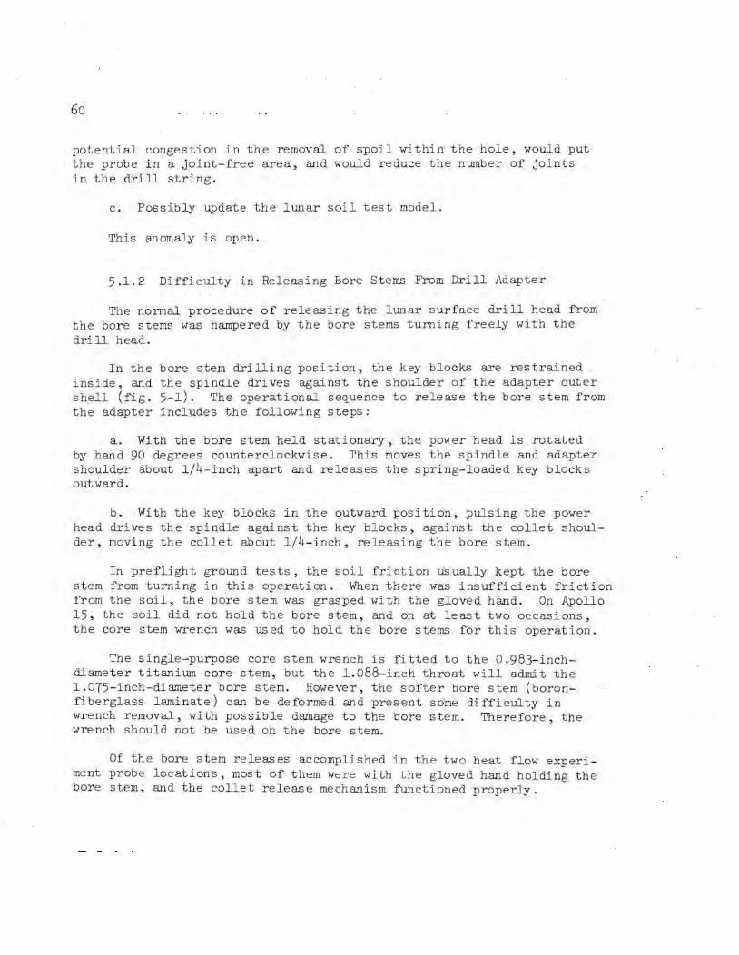
5.1.2 Difficulty in Releasing Bore Stems From Drill Adapter
The normal procedure of releasing the lunar surface drill head from the bore stems was hampered by the bore stems turning freely with the drill head.
In the bore stem drilling position, the key blocks are restrained inside, and the spindle drives against the shoulder of the adapter outer shell (fig. 5-1). The operational se~uence to release the bore stem from the adapter includes the following steps:
a. by hand shoulder outward.
With the bore stem held stationary, the power head is rotated 90 degrees counterclockwise. This moves the spindle and adapter
about 1/4-inch apart and releases the spring-loaded key blocks
b. With the key blocks in the outward position, pulsing the power head drives the spindle against the key blocks, against the collet shoulder, moving the collet about 1/4-inch, releasing the bore stem.
In preflight ground tests, the soil friction usually kept the bore stem from turning in this operation. When there was insufficient friction from the soil, the bore stem was grasped with the gloved hand. On Apollo 15, the soil did not hold the bore stem, and on at least two occasions, the core stem wrench was used to hold the bore stems for this operation.
The single-purpose core stem wrench is fitted to the 0.983-inchdiameter titanium core stem, but the 1.088-inch throat will admit the 1.075-inch-diameter bore stem. However, the softer bore stem (boronfiberglass laminate) can be deformed and present some difficulty in wrench removal, with possible damage to the bore stem. Therefore, the wrench should not be used on the bore stem.
Of the bore stem releases accomplished in the two heat flow experiment probe locations, most of them were with the gloved hand holding the bore stem, and the collet release mechanism functioned properly.

Outer shell
Dri II hammer force fed through spindle to shoulder of outer shell
! .: :.~. ~ '~ '.
Collet~
, \ . : ?-- - - - - - - - - - - ~
'( / / )
; ,./ .... "; I I I / I ~/ / /' / !\ . ...... .... / ........... J "l ..:" - _ .... 1 I ... .... ,.: ....... 1 L---- "
Drilling
Thread
Key pops
Manual rotation raises spindle
out when __ spindle israised~
,.J-; ___ _ __ _ __ ."I.,Outer shell
~ ' _--/: ~Jreleases collet /' -I ..... ,/ I
I I
~/> ,,", - /' / ,. -r'
"i / ' - -'I /< I
1_- --
Key block release
Figure 5-1.- Release of bore stem from drill.
Drill hammer force fed through key blocks to shou Ider of co lIet
~ .---
v: ~ 1": - ~
f/~ ~ ;X;
~ ~ ~ ~ /t -.r. ~ 0 1:\ ~ /.
J , I~------\
I \ I \ I \ I \ I \ I \ I \ I \ I \ I \
,1-.,------ - -- - l.. '( / / ,)
.................................. 1 I _/ /' I I .... /,.,... I I...... .................... ~ ~ ..... ...... J Icf.... ...... ~~.., I / / ' 1 L --- -"'-' /
Co Ilet and bore stem removal
0\ I-'

62
An improved procedure, as well as possible modifications, for contingency bore-stem holding are being investigated.
This anomaly is open.
5.1.3 Bore Stem Damage Near First Joint
The probe would not go to the bottom plug of the bottom bore stem in hole 2, but stopped at a point .about 6 inches above the first joint. Examination of photographs and data indicate that bore stem damage is holding the probe.
Ground tests have indicated that damage at a bore stem joint can progress into both the male and female halves under axial load drilling conditions. Under consideration are j oint design changes and surface procedures to preclude the initial damage.
This anomaly is open.
5.1.4 Difficulty in Core Stem Removal From the Drilled Hole in the Lunar Surface
Friction against the side walls of the hole and soil interference in the drill flutes can build up substantial forces against core stem removal in a deep hole in some soil formations. This was illustrated in premiss ion and drill development experiences.
Interference can be reduced and core stem removal eased by pulsing the power head when at the bottom of the hole with an upward and downward motion of the drill stem. However, in order to assure maximum core return and minimum core disturbance, the crew had been cautioned, and had elected, to use this procedure as little as possible. The core stem string was removed with considerable physical effort by the crew and a very complete core was recovered.
Methods and equipment (for example, manual jacks and drill-driven jacks) are being investigated to assist future crews in removing core stems while retaining core integrity and quantity within practical limits.
This anomaly is open.
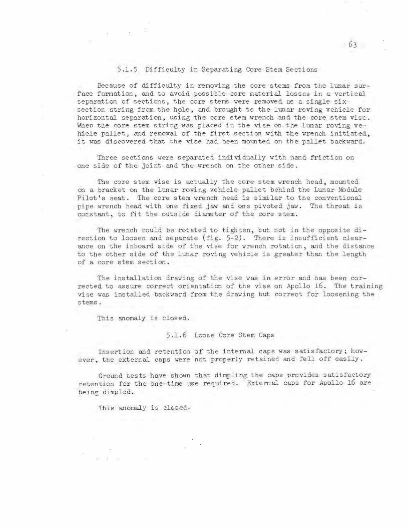
5.1.5 Difficulty in Separating Core Stem Sections
Because of difficulty in removing the core stems from the lunar surface formation, and to avoid possible core material losses in a vertical separation of sections, the core stems were removed as a single sixsection string from the h?le, and brought to the lunar roving vehicle for horizontal separation, using the core stem wrench and the core stem vise. When the core stem string was placed in the vi se on the lunar roving vehicle pallet, and removal of the first section with the wrench initiated, it was discovered that the vise had been mounted on the pallet backward.
Three sections were separated individually with hand friction on one side of the joint and the wrench on the other side.
The core stem vise is actually the core stem wrench head, mounted on a bracket on the lunar roving vehicle pallet behind the Lunar Module Pilot's seat. The core stem wrench head is similar to the conventional pipe wrench head with one fixed jaw and one pivoted jaw. The throat is constant, to fit the outside diameter of the core stem.
The wrench could be rotated to tighten, but not in the opposite direction to loosen and separate (fig. 5-2). There is insufficient clearance on the inboard side of the vise for wrench rotation, and the distance to the other side of the lunar roving vehicle is greater than the length of a core stem section.
The installation drawing of the vise was in error and has been corrected to assure correct orientation of the vise on Apollo 16. The training vise was installed backward from the drawing but correct for loosening the stems.
This anomaly is closed.
5.1.6 Loose Core Stem Caps
Insertion and retention of the internal caps was satisfactory; however, the external caps were not properly retained and fell off easily.
Ground tests have shown that dimpling the caps provides satisfactory retention for the one-time use required. External caps for Apollo 16 are being dimpled.
This anomaly is closed.

64
Vise grips this direction
Grips this direction
Wrench
Grips this direction
(a) Correct vise installation - will only loosen joint.
(b) Incorrect vise installation - will only tighten jOint.
Figure 5-2. - Installation of core stem vise on rover pallet.
Core
Vise
Core stem

5.1.7 Difficulty in Assembly of Core Stem Joints
It was more difficult to join sections of the core stems on the lunar surface than during preflight experience with other flight hardware.
The mating surfaces have a dry-lube coating for easy mating. Returned sections will be examined for possible lubricant removal, dimensional interference, and dust interference. The core stems are in the lunar receiving laboratory at this time.
This anomaly is open.
5.2 CENTRAL STATION REAR CURTAIN RETAINER REMOVAL LANYARD BROKE
In order to remove the retainer for the central station rear curtain added for Apollo 15, it was necessary to remove two retaining pins (fig. 5-3) . The two pins, a universal handling tool fitting, and the curtain retainer are joined by a three-section lanyard. When the universal handling tool was inserted in the fitting and raised to remove the first pin, the lanyard broke. When an effort was made to remove both pins simultaneously by inserting the handle under the lanyard joining the two pins, the lanyard broke there. The pins and retainer were then removed by hand.
A change to the Dacron lanyard from a 50-pound test rated material to a 120-pound test rated material is being considered with acceptance pull tests being increased from 20 pounds to 40 pounds. Also being considered is providing for individual straight pulls for removal of each pin and the curtain retainer.
This anomaly is open.
5.3 INTERMITI'ENT LOCK OF UNIVERSAL HANDLING TOOL
IN SUPRATHERMAL ION DETECTOR FITI'ING
While carrying the suprathermal ion detector experiment from the subpallet to the emplacement site, the experiment fell off the universal handling tool at least twice. The experiment experienced no visible damage and has been operating satisfactorily.

66
a. First lanyard break
Second retain ing pin
b. Second lanyard broken
Figure 5-3.- Central station rear curtain retainer removal.

The universal handling tool fitting on this experiment is the highest location above the lunar surface of any of the fittings and presents a more awkard posi tion of the tool for insertion, locking, and maintaining lock in the fitting (fig. 5-4). Premission records are being examined in regard to fit and pull tests of both universal handling tools with the fitting on each experiment.
Corrective action under consideration includes procedures to avoid inadvertant tool release triggering because of the positioning of the tool. The suprathermal ion detector experiment is not presently planned for any future missions.
This anomaly is open.

68
Universal handl ing tool
Su prathermal ion detector experiment
/1-4'--- Tool fitting
14 inches
40 inches
Figure 5-4.- Universal handling tool - suprathermal ion detector experiment interface.
6.0 GOVERNMENT FURNISHED EQUIFMENT ANOMALIES
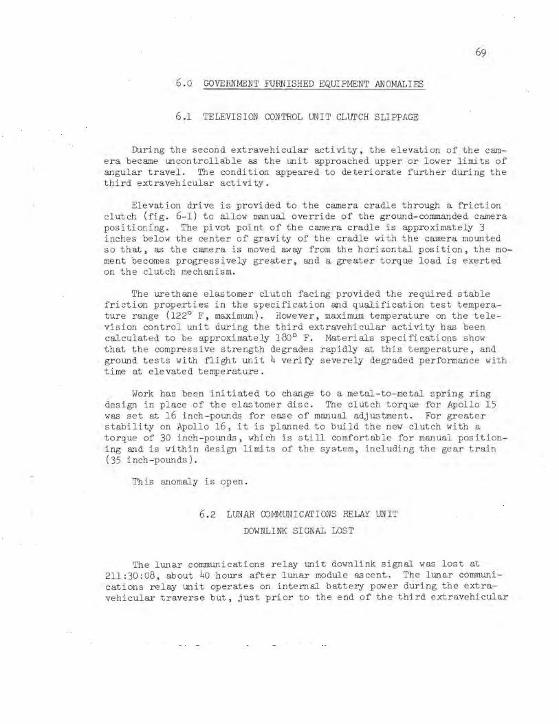
6.1 TELEVISION CONTROL UNIT CLUTCH SLIPPAGE
During the second extravehicular activity, the elevation of the camera became uncontrollable as the unit approached upper or lower limits of angular travel. The condition appeared to deteriorate further during the third extravehicular activity.
Elevation drive is provided to the camera cradle through a friction clutch (fig. 6-1) to allow manual override of the ground-commanded camera positioning . . The pivot point of the camera cradle is approximately 3 inches below the center of gravity of the cradle with the camera mounted so that, as the camera is moved away from the horizontal position, the moment becomes progressively greater, and a greater torque load is exerted on the clutch mechanism.
The urethane elastomer clutch facing provided the required stable friction properties in the specification and qualification test temperature range (122° F, maximum). However, maximum temperature on the television control unit during the third extravehicular activity has been calculated to be approximately 180° F. Materials specifications show that the compressive strength degrades rapidly at this temperature, and ground tests with flight unit 4 verify severely degraded performance with time at elevated temperature.
Work has been initiated to change to a metal-to-metal spring ring design in place of the elastomer disc. The clutch torque for Apollo 15 was set at 16 inch-pounds for ease of manual adjustment. For greater stability on Apollo 16, it is planned to build the new clutch with a torque of 30 inch-pounds, which is still comfortable for manual positioning and is within design limits of the system, including the gear train (35 inch-pounds).
This anomaly is open.
6.2 LUNAR COMMUNICATIONS RELAY UNIT
DOWNLINK SIGNAL LOST
The lunar communications relay unit downlink signal was lost at 211:30:08, about 40 hours after lunar module ascent. The lunar .comrnunications relay unit operates on internal battery power during the extravehicular traverse but, just prior to the end of the third extravehicular

Camera
Television contro I un it
Camera facing forward
Clutch fac ing (adiprene)
Drive shaft
Figure 6-1.- Camera elevation control clutch.
Bellevi lie washers (torgue adjustment)
--.l o

n
activity, the unit was manually switched to external lunar roving vehicle power in preparation for viewing lunar modu,J-e .ascent and for continuing television observations until 6 days after ascent. The power distribution from the lunar roving vehicle to the television is shown in figure 6-2. The television and transmitter had been commanded on from the ground 13 minutes prior to RF downlink signal loss. The lunar communications relay unit status subcarrier had been commanded on 7 minutes prior to signal loss. The television camera was stationary and a l-second incremental iris movement was occurring at this time.
The signal deterioration transient characteristics from flight and postflight test data are shown in figure 6-3. The flight data shows that the automatic gain control measurement began to fall (transmitter power falls as 28-volt dc power decreases) followed by the video signal decay which, in turn, was followed by the decay of the lunar communications relay unit temperature measurement (temperature measurement falls as 14-volt dc power decreases). The RF signal level then decreased below the ground receiver's threshold as indicated by complete signal loss. The overall loss of the downlink signal within 5 milliseconds is indicative of 28-volt dc power loss. Decay of the temperature measurement is indi cati ve of 16.5-volt dc power loss. The lunar communications relay unit dc-to-dc converter (fig. 6-2) supplies both the 28-volt and 16.5-volt dc power. To verify loss of 16.5-volt power, an uplink voice signal was transmitted to key the VHF transmitter on. No signal was received on the Stanford 150-feet VHF antenna which indicates that the VHF transmitter, powered via 16.8-volts dc, was inoperative.
In laboratory tests, numerous types of faults were induced into the lunar communications relay unit developmental unit and associated groundcontrolled television assembly and lunar rover vehicle interfaces to determine whether the transient characteristics of the flight signal could be duplicated. The fault which duplicated the flight signal was the opening of the lunar roving vehicle power line prior to the 440-microfarad capacitor (figs. 6-2 and 6-3). The Tests, show that the decay time of the lunar communication relay unit 28-volt and 14-volt power is increased by discharge of the 440-microfarad capacitor. Other induced faults resulted in shorter power decay times, affecting the received signal accordingly. The temperature measurement output (see thermistor in fig. 6-2) is proportional to the decay in 14-volt power. Consequently, the 6-percent decay of the flight temperature signal corresponds to a 1.4-volt decay. This characteristic was exactly duplicated when the lunar roving vehicle power line was opened. The 28-volt power decayed to 21.8-volts dc when the 14-volt power decayed to 12 .6-volts. The RF transmi tter power at this voltage will be decreased by 6.4 dB, which accounts for total signal los s at this exact time since the ground receiver would be below its threshold. This characteristic was also duplicated with the flight data when the lunar

72
o
-97dBm
Ground receiver automatic gain control
Zero signal
Ground controlled television assembly video
6 percent signal decay
Lunar communications relay unit temperature measurement
20 40 60 Time, mi II iseconds
\al Flight data.
80 o
-97dBm
~ Zero Ground receiver auto- ~---- signal matic gain control
Ground controlled television assembly video
6 percent
Lunar communications relay unit temperature measurement
II
28Vdc II
~ Lunar communications relay ~---- OV unit internal 28V dc
II II
14Vd, ~
Lunar communications relay -------OV unit internal 14V dc
34V dc
~---------------OV
20
Lunar roving vehicle internal 34V dc
40 60
Time, mill iseconds
80
b, Postflight simulated ground test data.
100
Figure 6-2.- Loss of pOwer to lunar communications relay unit.
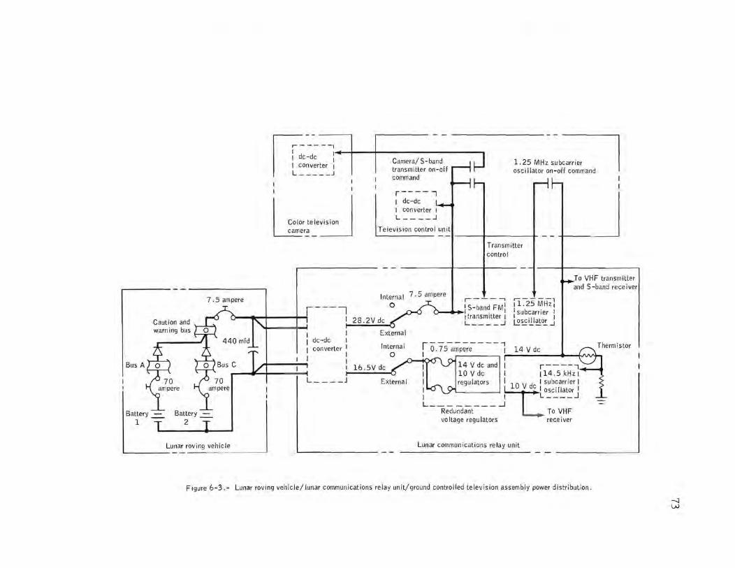
Bus A
Battery -=-1
7.5 ampere
Lunar roving vehicle L-.. __ _
~I -------1:1~.. ~ I dc-dc I I converter I
L - -- - _J command
1.25 MH, "b~ osci lIator on-off command
I I I
I
I Col" t,I"""o I LJ;ra ::J
dc-dc converter
L ____ J
r----, I dc-dc I I converter I L ____ ...l
Television control unit
28 . 2V dc
External
7.5 ampere
T ransm i tter control
r------, ~: S-band FMI
Itransmitter :
,---- -, 11.25MHz 1 : subcarrier I
L ____ .J ~~iJ..I~o.!:.J
.To VHF transmitter and S -band rece i ver
rO.75-;.;p;.:e----j 14Vdc
~-+c1 KJ\ I • (~ I 14Vdcand I r-----, 16.5Vdc I 10Vdc I 114.5kHzl I regulators I 10 V dc I subcamer I I fCOSCtl,ator I I I L ____ J
L_ "R;du-;;d;:;t- - - -.J To VHF
vo Itage regu lators rece I ver
Lunar communications relay unit
Figure 6-3.- Lunar roving vehicle/lunar communications relay unit/ground controlled television assembly power distribution .
---:] w

14
roving vehicle circuit was opened . In summary, the test shows either the 1.5-ampere circuit breaker popped, or a wire opened upstream of the 440-microforad capacitor.
The lunar communications relay unit draws about 3.0 amperes. The circuit breaker should not have opened unless the dc-to-dc converter was drawing excessive current or the circuit breaker was sufficiently hot to reduce the trip level to 3 amperes. Additional analysis and tests are being performed on the ~lunar communications relay unit converter to dedermine if it could have drawn excessive current.
Addition of a manual switch in the lunar rover circuit to override the circuit breaker after completion of lunar roving activity is being considered for Apollo 16.
The anomaly is open.
6.3 LUNAR SURFACE 16-MM CAMERA MAGAZINES JAMMED
The crew experienced film jams with the lunar surface 16-mm camera film magazines. Five out of eight magazines transferred to the lunar surface jammed, two were not used, and one successfully transported film to completion.
Analysis of the returned magazines indicated two contributing factors to jamming .
a . The first magazine installed showed, by damage to the 'nagazine dri ve spline and scratches on the front face, that installation in the camera was improper and the magazine and camera were misaligned. Misalignment of the floating female spline of the camera with the male spline of the magazine was such that metal was removed from the brass male spline . The magazine spline shaft is attached to the metering sprocket (fig. 6-4) . Mismating results in depleting the film supply loop without allowing replenishment and takeup through the drive spline/metering sprocket mechanism. The lower, or takeup, loop becomes accordion folded, thereby jamming in the metering sprocket gate (fig 6-4). Two other magazines exhibited damaged drive splines, indicating that mismating occurred on at least three occasions . Pictures taken of the lunar roving vehicle with photographs taken with the lunar surface 70-mm camera show that a strip of tape installed on the 16-mm camera magazine for latch stowage protection was not removed prior to installation of a film magazine. Leaving the tape strip in place does not allow the magazine latch to move down for normal magazine installation. Although the crew reported no problem with magazine installation in this condition, this could have contributed to the camera/magazine mismating.

Film supply
Pressure plate-
Aperature
Normal supply loop
,---I \
Metering sprocket
Film take-up core
Figure 6-4.- Lunar surface 16mm camera magazine.
End-of-fi 1m metering arm
-..J \Jl

76
b. In the course of troubleshooting, the crew manually advanced the film in all remaining magazines prior to the second extravehicular activity and again prior to the third extravehi cular activity. The amount of manual advancement varied from five to twenty-one frames in the several jammed magazines. The film supply loop (fig.6-4) co ntains three to five frames excess. The normal procedure is to advance manually not more than one frame to verify perforation indexing. The excessive advancement depleted the film supply loops in all magazines, creating again the excessive takeup loop condition causing accordion folding and jamming in the metering sprocket (fig. 6-4).
Hardware analysis, air-to-ground voice tapes, and crew debriefing indicate that the lunar surface camera fUnctioned properly, and the jammed magazines resulted from procedural errors. Corrective actions are: insuring adequate crew training through scheduled prelaunch briefings, stressing malfunction procedures and corrective actions, and putting a removal labe I on the tape.
This anomaly is closed.
6.4 LUNAR MODULE PILOT'S 70-MM CAMERA
FILM ADVANCE STOPPED
Near the end of the second extravehicular activity, the 70-mm camera had ceased to transport film. The crew, after return to the lunar module, cleared the problem, and the camera was used again on the third extravehicular activity. However, after a short series of exposures had been made, the failure recurred. The camera was cleared again in the spacecraft and was utilized for additional photography during the transea.rth phase without recurrence of the problem, although a screwdriver was required to release one of the magazine latches.
The crew used the 70-mm camera systems on the lunar surface as a support for sample bags during closure operations. This suggests that dust could have caused the problem. However, postflight examination showed that the magazines were not jammed, and the film shows that the exposures made with the camera were satisfactory.
Analysis of the hardware, which included operational testing, disassembly and inspection, and measurement of battery charge, showed no cause for the problems. However, operational testing with film loads indicated proper film transporting until approximately 200 cycles have been accumulated, at which time the fai lure mode was dupli cated several times in succession. The drive mechanism operated freely, but the torque was insufficient. The motor and drive mechanism will be analyzed.
•
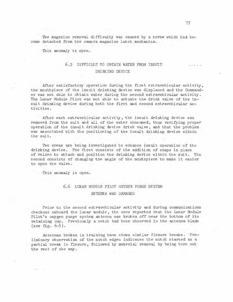
II
The magazine removal difficulty was caused by a screw which had become detached from the camera magazine latch mechanism.
This anomaly is open.
6.5 DIFFICULT TO OBTAIN WATER FROM INSUlT
DRINKING DEVICE
After satisfactory operation during the first extravehicular activity, the mouthpiece of the insuit drinking device was displaced and the Commander was not able to obtain water during the second extravehi cular activity. The Lunar Module Pilot was not able to actuate the drink valve of the insuit drinking device during both the first and second extravehicular activities.
After each extravehicular acti vi ty, the insui t drinking device was removed from the suit and all of the water consumed, thus verifying proper operation of the insuit drinking device drink valve, and that the problem was as sociated with the positioning of the insui t drinking device within the suit.
Two areas are being investigated to enhance ins ui t operation of the drinking device. The first consists of the addition of snaps in place of velcro to attach and position the drinking device within the suit. The second consists of changing the angle of the mouthpiece to make it easier to open the valve.
This anomaly is open.
6.6 LUNAR MODULE PILOT OXYGEN PURGE SYSTEM
ANTENNA WAS DAMAGED
Prior to the second extravehicular activity and during communications checkout onboard the lunar module, the crew reported that the Lunar Module Pilot's oxygen purge system antenna was broken off near the bottom of its retaining cup. Previously a notch had been observed in the antenna blade (see fig. 6-5).
Antennas broken in training have shown similar flexure breaks. Preliminary observation of the notch edges indicates the notch started as a partial break in flexure, followed by material removal by being torn out the rest of the way.
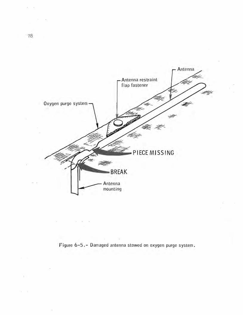
78
Oxygen purge system
Antenna restraint flap fastener
__ PIECEMISS ING
--BREAK
mounting
Figure 6-5. - Damaged antenna stowed on oxygen purge system .

79
The material in the returned antenna is being tested for physical properties including brittleness which could account for easy breaking. Possible changes in deployment and stowage of the antenna are under consideration.
This anomaly is open .
NASA-MSC